1
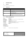
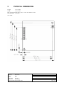
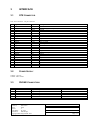
DELTA DESIGN
MODEM MODULE IM336S
USER MANUAL
DELTA DESIGN BVBA
Tiensesteenweg 45
B3360 Korbeek-lo
Tel : +32 16 461575
Fax: +32 16 461595
[email protected]
DOCUMENT HISTORY
Date
17/02/2003
02/04/2003
Version
1.0
1.1
03/11/2004
2
Status
DocNumber:
MD_IM336S
Author(s):
Marc Decré
Status:
Draft
Version:
2
VersionDate:
03/11/04
Distribution
Delta Design
Copyright Delta Design BVBA 2004
Author
Marc Decré
Marc Decré
Marc Decré
Change
Creation
Changes 4 SIA protocol support
110 bps will not be supported
Listen-in mode description
Cleanup, pictures
Page: 1 / 9
TABLE OF CONTENTS
1
INTRODUCTION.......................................................................................................................................................... 3
1.1
1.2
1.3
PURPOSE ..........................................................................................................................................................................3
REFERENCES...................................................................................................................................................................3
GENERAL MODEM FEATURES.......................................................................................................................................3
2
PHYSICAL DIMENSIONS......................................................................................................................................... 4
3
INTERFACE................................................................................................................................................................... 5
3.1
3.2
3.3
4
DTE CONNECTOR..........................................................................................................................................................5
POWER SUPPLY ..............................................................................................................................................................5
PHONE CONNECTORS..................................................................................................................................................5
MODEM OPERATION ............................................................................................................................................... 6
4.1
AT COMMAND SET ........................................................................................................................................................6
4.1.1
Kn Keyabort .................................................................................................................................................6
4.1.2
ATRn RINGBACK REPORTING...........................................................................................................6
4.1.3
ATUn SHORT CONNECT MESSAGE .................................................................................................6
4.1.4
AT%Mn Hardware speaker Mute.............................................................................................................6
4.1.5
AT%Sn SIA mode.......................................................................................................................................6
4.2
SIA PROTOCOL SUPPORT ..............................................................................................................................................6
4.2.1
Modem initialisation...................................................................................................................................7
4.2.2
ACK – NACK response frames ................................................................................................................7
4.2.3
Listen in operation.......................................................................................................................................7
4.3
DTMF..............................................................................................................................................................................8
5
COMPLIANCE .............................................................................................................................................................. 9
DocNumber:
MD_IM336S
Author(s):
Marc Decré
Status:
Draft
Version:
2
VersionDate:
03/11/04
Distribution
Delta Design
Copyright Delta Design BVBA 2004
Page: 2 / 9
1
INTRODUCTION
1.1
PURPOSE
This document describes the MI336S MODEM MODULE .
1.2
REFERENCES
(1)ETSI
(2)ETSI
(3)SIA
ETSI TBR21 Edition Januari 1998
ETS 300.001 1998-10
Digital Communications Standard – ‘SIA Format’ Protocol – for Alarm
System Communications SIA DC-03-1990.01 (R2000.11) Publication
Order Number : 14083
Doc. No. 102184B AT Commands for CX81801 SmartV.XX,
CX06833 SMXXD, CX81300 SmartACF, and CX06827 SCXXD
Modems Reference Manual
Access and Terminals (AT);
Harmonized basic attachment requirements for Terminals for connection
to analogue interfaces of the Telephone Networks; Update of the
technical contents of TBR 021, EN 301 437, TBR 15, TBR 17;
Part 1, 2 and 3
(4)Conexant
(5)ETSI
1.3
GENERAL MODEM FEATURES
Dimensions
Heigth
Modem Protocol
Error Correction :
Data Compression
Alarm protocols
DTE interface
Data Format
Command set
Power Supply
: 56mm x 56 mm
: max 20 mm
:V.34 / V.32bis / V.32 / V.22bis / V.22/ V.21 / V.23 / Bell212A / Bell103/
: V.42 / MNP4
: V.42bis /MNP5
: SIA support / DTMF (receive /transmit)
: V.24/V.28
: Serial Asynchronous, 7 or 8 data bits, o,e or no parity, one or two stop bits
: Hayes, subset of V.250 / V253
: 3.3 Vdc 5% : max 170 mA (measured 158 mA)
: optional 5Vdc
: PSTN
Line Interface
Watchdog function
Line-In-Use detection
Digital Protection
Parallel Pickup detection
Line Voltage monitoring
Compliance
: TBR21 januari 1998 , TS103021 (2003-2004)
DocNumber:
MD_IM336S
Author(s):
Marc Decré
Status:
Draft
Version:
2
VersionDate:
03/11/04
Distribution
Delta Design
Copyright Delta Design BVBA 2004
Page: 3 / 9
2
PHYSICAL DIMENSIONS
Length
56 ± 0.2 mm
Width
56 ± 0.2 mm
Max component height (above pcb) : TOP 6 mm Bottom : 2mm
Mounting holes D 2.8 mm
TOP VIEW
DocNumber:
MD_IM336S
Author(s):
Marc Decré
Status:
Draft
Version:
2
VersionDate:
03/11/04
Distribution
Delta Design
Copyright Delta Design BVBA 2004
Page: 4 / 9
3
INTERFACE
3.1
DTE CONNECTOR
TTL 3V3 Connector - 24 pin connector
Pin
1
2
3
4
5
6
7
8
9
10
11
12
13
14
15
16
17
18
19
20
21
22
23
24
Type
Signal
GND
VCC
GND
/TXD
GND
/RXD
ID-PIN2
/RTS
ID-PIN1
/CTS
/RESET
/DTR
/OH
/DCD
/RI
/DSR
UA
UE
UA2
UE2
GND
SPK
MIC
GND
Supply
Input
Output
Output
Input
Output
Output
Input
Input
Output
Output
Output
Output
Output
Input
Output
Input
Output
Input
3.2
Description
Ground
3V3 DC supply ( 5V optional)
Ground
Transmit Data
Ground
Receive Data
GND
Request To Send
GND
Clear To Send
Reset Input
Data Terminal Ready
Off Hook
Data Carrier Detect
Ring Indicator
Data Set Ready
Output
Input
Output 2
Input 2
Ground
Speaker
Microphone
Ground
POWER SUPPLY
Voltage : 3V3 5%
Current : Max 170mA
3.3
Pin
1
2
3
4
5
6
PHONE C ONNECTORS
Signal
LA
LA’
LB
LB’
NC
NC
Description
Telephone signal
Telephone signal
Telephone signal
Telephone signal
DocNumber:
MD_IM336S
Author(s):
Marc Decré
Status:
Draft
Version:
2
VersionDate:
03/11/04
Distribution
Delta Design
Copyright Delta Design BVBA 2004
RJ11 Pin
3
2
4
5
Page: 5 / 9
4
MODEM OPERATION
4.1
AT COMMAND SET
For a complete command description , see ref(4) .
Following extra commands are implemented
4.1.1
Kn Keyabort
When enabled, the modem will disconnect when it receives a character from the host during call progress.
ATK0
ATK1
4.1.2
ATR0
ATR1
disable keyabort
enable keyabort (default)
ATRn RINGBACK REPORTING
disable ringback report (default)
enable ringback reporting
When enabled, the modem will report ringback signals with the RINGING message ( code 14)
4.1.3
ATU0
ATU1
ATUn SHORT CONNECT MESSAGE
disable short connect message
enable short connect message (default)
When enabled only the CONNECT message is given on connection established.
4.1.4
AT%Mn Hardware speaker Mute
AT%M0The speaker output will be muted
AT%M1The speaker output is not muted (default)
4.1.5
AT%S0
AT%S1
4.2
AT%Sn SIA mode
Non SIA mode, standard modem operation
SIA mode
SIA PROTOCOL SUPPORT
The modem will allow the host alarm exchange + modem to act as a SIA transmitter.
The modem will implement the low level requirements of the SIA protocol. The higher level features will be
implemented in the host alarm exchange.
The SIA support features in the modem are configurable via AT commands and/or Sregisters. A programmed
SIA configuration can be stored in non volatile memory and automatically loaded after power-up or reset.
The SIA listen-in feature will be supported.
Following features of the SIA protocol are supported :
DocNumber:
MD_IM336S
Author(s):
Marc Decré
Status:
Draft
Version:
2
VersionDate:
03/11/04
Distribution
Delta Design
Copyright Delta Design BVBA 2004
Page: 6 / 9
-Handshake tone detection
-Speed Synchronization Signal generation (300 baud )
-Incoming Tonal Positive Acknowdledge (ACK) from the SIA receiver will be translated into an “Eight Block –
Data Acknowledgment and send to the host.
- Incoming Tonal Negative Acknowledge(NACK) from the SIA receiver will be translated into an “Zero Block”
and sent to the host.
-Communication with the host will be by default 9600bps , 1start bit,8 databits , 1 stopbit.
-Communication to the SIA receiver is 1 start bit, 8 databits , odd parity bit and 2 stop bits BELL 103 (300
Baud). The modem will insert / delete the necessary parity and stop bits.
-To switch the modem to listen-in mode, the host will give the escape sequence and switch the modem to
speakerphone mode
-In listen –in mode , speech signal from the modem speech input will be transmitted to the phone line and
incoming speech from the phone line will be transmitted on the modem speech output.
-The speech output can be muted.
4.2.1
Modem initialisation
The following initialization needs to be sent to the modem to initialize it for SIA operation :
AT&F
AT%S1
;reset factory defaults
;init SIA
After a call is made to the SIA receiver, the modem will wait for the handshake tone.
When the handshake tone is received, the modem will report the CONNECT message and activate DCD signal.
Host needs to send the first packet immediately following connect message.
4.2.2
ACK – NACK response frames
ACK : when the modem receives a tonal positive acknowledgement from the host, it will send an “eight block”
to the host. Byte Sequence (hex): 40 38 87
NACK : when the modem receives a tonal negative acknowledgement from the host, it will send a “zero block”
to the host . Byte sequence (hex): 40 30 8F
4.2.3
Listen in operation
The modem supports listen in operation by means of the Conexant Speakerphone feature.
The modem can switch from SIA communication mode to full duplex speakerphone operation as follows:
Go to online command mode bye means of the escape sequence ( +++)
AT%S0
;disable SIA mode
AT+FCLASS=8 ;enable voice mode
ATO
;go on line
(wait now for OK , not for CONNECT !!)
AT+VSP=1
;enable full duplexspeakerphone mode
The modem accepts the speech input via the microphone input .
The speech output is via the speaker output.
Speech output can be muted with the at%m1 command.
The modem can also transmit and receive DTMF in this mode.
DocNumber:
MD_IM336S
Author(s):
Marc Decré
Status:
Draft
Version:
2
VersionDate:
03/11/04
Distribution
Delta Design
Copyright Delta Design BVBA 2004
Page: 7 / 9
4.3
DTMF
The modem supports the generation and detection of DTMF tones via AT command/response according to DLE
encapsulation. See ref (4)
DocNumber:
MD_IM336S
Author(s):
Marc Decré
Status:
Draft
Version:
2
VersionDate:
03/11/04
Distribution
Delta Design
Copyright Delta Design BVBA 2004
Page: 8 / 9
5
COMPLIANCE
Modem is designed to comply with TBR21 01/1998 and TS103021.
A compliance testreport is available.
.
DocNumber:
MD_IM336S
Author(s):
Marc Decré
Status:
Draft
Version:
2
VersionDate:
03/11/04
Distribution
Delta Design
Copyright Delta Design BVBA 2004
Page: 9 / 9