1
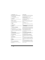
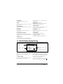
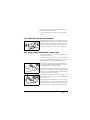
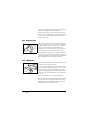
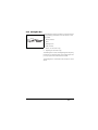
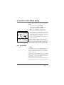
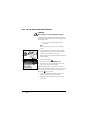
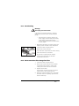
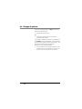
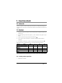
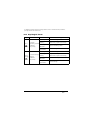
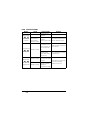
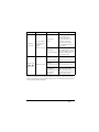
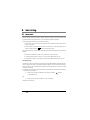
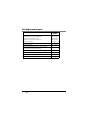
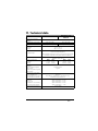
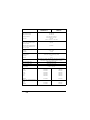
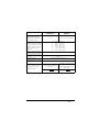
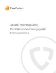
VENTImotion 2
Home ventilation device
Description of device and instructions for use
for devices from serial number 10,000
Contents
1.
1.1
1.2
1.3
1.4
2.
2.1
2.2
2.3
3.
3.1
3.2
3.3
3.4
4.
4.1
4.2
4.3
4.4
5.
5.1
5.2
5.3
5.4
5.5
6.
6.1
6.2
6.3
6.4
7.
7.1
7.2
8.
8.1
8.2
9.
2
Overview . . . . . . . . . . . . . . . . . . . . 3
Default display during therapy . . . . 5
Symbols used in the display . . . . . . 6
Abbreviations used in the display . . 7
Safety instructions . . . . . . . . . . . . . 8
Description of device . . . . . . . . . . 9
Intended use . . . . . . . . . . . . . . . . . 9
Owner/operator and user
qualification . . . . . . . . . . . . . . . . . . 9
Description of function . . . . . . . . . 10
Safety instructions . . . . . . . . . . . 12
Safety information . . . . . . . . . . . . 12
Contraindications . . . . . . . . . . . . . 14
Side effects . . . . . . . . . . . . . . . . . 15
Particular markings on the device 16
Set up device . . . . . . . . . . . . . . . . 18
Set up device . . . . . . . . . . . . . . . . 18
Connect device . . . . . . . . . . . . . . 18
Put on breathing mask . . . . . . . . . 20
Accessories. . . . . . . . . . . . . . . . . . 20
Operation . . . . . . . . . . . . . . . . . . . 24
Start up VENTImotion 2 . . . . . . . . 24
Functions in the default display. . . 25
Functions in the menu . . . . . . . . . 27
After use . . . . . . . . . . . . . . . . . . . 30
Traveling with VENTImotion 2. . . . 31
Hygiene treatment . . . . . . . . . . . 32
Intervals . . . . . . . . . . . . . . . . . . . . 32
Cleaning . . . . . . . . . . . . . . . . . . . 33
Disinfect, sterilize . . . . . . . . . . . . . 36
Change of patient . . . . . . . . . . . . 38
Function check . . . . . . . . . . . . . . . 39
Intervals . . . . . . . . . . . . . . . . . . . . 39
Method . . . . . . . . . . . . . . . . . . . . 39
Faults . . . . . . . . . . . . . . . . . . . . . . . 44
Faults . . . . . . . . . . . . . . . . . . . . . . 44
Alarms . . . . . . . . . . . . . . . . . . . . . 45
Servicing . . . . . . . . . . . . . . . . . . . . 50
EN
Contents
9.1
9.2
9.3
9.4
10.
10.1
10.2
10.3
11.
11.1
11.2
12.
Intervals . . . . . . . . . . . . . . . . . . . . 50
Filter change . . . . . . . . . . . . . . . . 51
Change pressure measurement
tube . . . . . . . . . . . . . . . . . . . . . . . 53
Disposal . . . . . . . . . . . . . . . . . . . . 54
Scope of supply . . . . . . . . . . . . . .55
Standard scope of supply . . . . . . . 55
Accessories. . . . . . . . . . . . . . . . . . 55
Replacement parts . . . . . . . . . . . . 58
Technical data . . . . . . . . . . . . . . . .59
Pneumatic diagram . . . . . . . . . . . 63
Safety distances . . . . . . . . . . . . . . 64
Warranty . . . . . . . . . . . . . . . . . . . .65
13.
Declaration of conformity . . . . .66
1. Overview
VENTImotion 2
1 Bacteria filter
11 Drying adapter
17 Head strap
2 Power supply
unit
16 Breathing mask
3 Power cord
15 Exhalation system
10 Sealing plugs (2x)
9 Device outlet port
4 Cable-securing clip
14 Tube system
13 Pressure
measurement tube
5 Handle
6 Serial ports
12 Adapter
7 Control panel and displays
8 Connection for respiratory air humidifier
18 Service label and safety check (STK) label
(Germany only)
23 Alarm acknowledgement key with LED
24 On/Off key
25 Dial
22 Connection for
O2-supply valves
26 Operating keys
20 Power supply
29 Softstart key 27 Menu key
connection (yellow) 21 Connection for
battery VENTIpower
28 Humidifier key with LED
19 Filter compartment lid, air inlet
31 Device ID plate
32 VENTIclick
30 VENTIpower
34 VENTI-O2 / VENTI-O2 plus
33 Carrying bag
Overview
EN
3
1
Bacteria filter (accessory)
For protecting the device from contamination
when several patients are using the device.
2
Power supply unit
For providing the device with power.
3
Cable-securing clip
Prevents the device being disconnected from the
power supply inadvertently.
5
Handle
For lifting the device.
6
The air flows to the mask through the tube system. The tube system consists of a creased tube,
pressure measurement tube and adapter.
15 Exhalation system (accessory)
This is where the exhaled air containing carbon dioxide escapes during therapy.
Power cord
Connects the power supply unit to the power
supply.
4
14 Tube system
Serial ports
For connecting to devices to display and evaluate
therapy data.
16 Breathing mask (accessory)
Respiratory air at the required therapy pressure is
administered to the patient via the breathing
mask.
17 Head strap (accessory)
For correct, secure positioning of the breathing
mask.
18 Service label and safety check (STK) label
(Germany only)
For controlling and monitoring the device and
connected accessories.
The service label indicates when the next service
is required. The safety check [STK] label (Germany
only) indicates when the next safety check as per
§6 of the German law governing medical devices
and their owners/operators is required.
8
19 Filter compartment lid, air inlet
7
Control panel and displays
Connection for respiratory air humidifier
For connecting the VENTIclick respiratory air humidifier.
For covering and securely positioning the coarse
dust and fine filters.
9
20 Power supply connection (yellow)
Device outlet port
The respiratory air flows to the patient from here
via the tube system and breathing mask.
This is where the connecting cable for the power
supply unit is connected.
10 Sealing plugs (2x)
21 Connection for battery VENTIpower
For sealing the pressure measurement tube during cleaning.
For the VENTIpower electricity supply-independent power supply available as an accessory (accessory).
11 Drying adapter
Required to dry the tube system and for the function check.
22 Connection for O2 supply valve VENTI-O2
12 Adapter
For connecting the VENTI-O2 and VENTI-O2 plus
oxygen supply valves available as an accessory (accessory).
For connecting the tube system to the device outlet port.
23 Alarm acknowledgement key with LED
13 Pressure measurement tube
For measuring the pressure prevailing in the
breathing mask.
4
EN
Overview
The alarm acknowledgement key is for the temporary muting of alarms. The LED is for displaying
the alarms visually.
24 On/Off key
In TA mode, this key is for triggering an analysis
phase manually.
For switching the device on and off.
30 VENTIpower (accessory)
25 Dial
Central control element of the device, for navigating in the menu.
Obtainable as an accessory, for electricity-independent power supply of the device.
31 Device ID plate
26 Operating keys
For the doctor to make rapid settings, disabled in
Patient mode.
Provides information about the device, such as serial number and year of manufacture.
32 VENTIclick (accessory)
27 Menu key
For switching from the default display to the
menu and back.
Obtainable as an accessory; for humidifying and
heating respiratory air.
33 Carrying bag
28 Humidifier key with LED
For setting humidifier stage. Six stages are available. The LED indicates whether the humidifier is
activated.
For transporting the VENTImotion 2.
34 VENTI-O2 /VENTI-O2 plus (accessory)
For supplying oxygen to the breathing mask.
29 Softstart key
For activating Softstart and for setting Softstart
time up to the maximum value set by the doctor.
1.1 Default display during therapy
2 Softstart symbol
1 Status line
7
Active ventilation
mode
3 Display for respiratory phase
change
6 Ventilation parameters
4 Access to patient menu
5 Bar graph for pressure display
1
Status line
This is where information about device status, for
example filter change or servicing due, is displayed.
2
Softstart symbol
Indicates that Softstart is activated, the number
indicates remaining time in minutes.
3
Display for respiratory phase change
Indicates whether the current respiratory phase
change is spontaneous or mandatory (spontaneous: S, mandatory: T); depending on the respiratory phase, the display switches from left
(inspiration) to right (exhalation).
Likewise indicates whether the inspiration trigger
at the start of an exhalation stage is blocked ( ),
Overview
EN
5
due to trigger lockout time being activated, for
example.
4
Access to patient menu
The key next to this menu item enables you to
switch to the menu and back to the default display.
5
For the graphical display of therapy pressure.
6
Ventilation parameters
Corresponding current ventilation parameters are
displayed as a function of which mode is active.
7
Active ventilation mode
The ventilation mode which is active is displayed
at this point in the status line.
Bar graph for pressure display
1.2 Symbols used in the display
Symbol
Meaning
Status line
Softstart active, remaining time faded in
Filter change required
Acoustic signal for IPAPmin and VTmin alarms silent
Alarm for IPAPmin and VTmin alarms deactivated
Servicing required
Physician functions enabled
Physician functions locked
Fan off
Main window
Low-priority alarm triggered
Medium-priority alarm triggered
6
EN
Overview
1.3 Abbreviations used in the display
Symbol
Meaning
Status line
T
T mode active
TA
TA mode active
ST
ST mode active
CPAP
CPAP mode active
AA
Device in TA mode, automatic analysis phase running
AM
Device in TA mode, manual analysis phase running
+V
Volume compensation activated (comes after mode, e.g. ST+V)
+A
AirTrap control activated (comes after mode, e.g. ST+A)
IPAP
Inspiration pressure
EPAP
Exhalation pressure
hPa
Pressure quoted in hectopascals; 1.01973 hPa correspond to 1 cm H2O.
f
Respiratory frequency
S
Spontaneous triggering of respiratory phase change
T
Mandatory triggering of respiratory phase change
B
Inspiration trigger blocked during an exhalation
Main window (default display)
Overview
EN
7
1.4 Safety instructions
Safety instructions indicate information relevant to safety.
You will find safety instructions within instructions before a step which includes a
risk to people or objects.
Safety instructions consist of
–
–
–
–
the warning symbol (pictogram),
a word to indicate the level of hazard
information about the hazard and
instructions on how to avoid the hazard.
There are three levels of warning instruction, depending on the degree of hazard.
DANGER!
Indicates an unusually large hazard. If you do not follow this
instruction, severe, irreversible injuries or death will result.
Warning!
Indicates an unusually large hazard. If you do not follow this
instruction, severe, irreversible injuries or fatal injuries may result.
Caution!
Indicates a hazard. If you do not follow this instruction, slight or
moderate injuries may result.
Note!
Indicates material hazards. If you do not follow this instruction, material
damage may result.
8
EN
Overview
2. Description of device
2.1 Intended use
VENTImotion 2 is a ventilation device for non-invasive ventilation in home caretype environments (not for life-support purposes) of adult patients with respiratory insufficiency who have a tidal volume of at least 160 ml and can be proven to
have an independent respiratory drive. This corresponds to the following diseases:
•
obstructive respiratory disorders such as COPD
•
restrictive respiratory disorders such as scolioses, deformities of the
thorax
•
neurological, muscular and neuromuscular disorders, such as
pareses of the diaphragm, for example
•
central respiratory regulation disorders
•
obstructive sleep apnea syndrome (OSAS)
VENTImotion 2 is not suitable for life-support use.
2.2 Owner/operator and user qualification
As an owner/operator or user, you must be familiar with the operation of this
medical device.
Observe the legal requirements for operation and use (in Germany, the regulations governing owner/operators of medical devices apply in particular). Basic recommendation: get a person authorized by Weinmann to provide you with proper
instruction about the handling, use and operation of this medical device.
You may only make individual settings to this device for a specific patient if you
are the physician supervising treatment.
When the device is handed over to a patient, as the physician supervising treatment or a member of the hospital staff you must provide instruction in the function of the device.
Description of device
EN
9
2.3 Description of function
2.3.1 Display and operation
The parameters below can be read off the display.
•
Therapy mode
•
CPAP or IPAP and EPAP
•
Respiratory frequency (f)
•
Spontaneous or mechanical respiratory phase change
•
Pressure change
Your doctor can set the ventilation parameters in standby and in normal mode.
Your doctor can set the device using several keys which allow direct access to the
most important parameters:
•
IPAP
•
EPAP
•
frequency
•
inspiration time
The dial is used to control navigation through the menu.
2.3.2 Provision of therapy pressure
A fan takes in ambient air through a filter and pumps it to the device outlet port.
The air flows to the patient from here through the tube system and the breathing
mask.
Sensors detect the pressure in the breathing mask and in the tube system, as well
as the respiratory phase change (trigger point). The fan provides the IPAP and
EPAP pressures set by the doctor to suit this information.
10
EN
Description of device
2.3.3 Therapy modes
The device can be operated in the following therapy modes: T, TA, ST, CPAP. The
mode required for your therapy will be set on the device by your doctor.
In adaptive, controlled TA mode, the device automatically adapts to your personal
respiratory rhythm and provides therapy pressure at precisely this rhythm.
In time-controlled mode T and in assisted-controlled mode ST, your doctor can set
respiratory frequency in a range from 6 to 45 breaths per minute and inspiration
time in a range from 15 % to 67 % of respiratory period.
In assisted-controlled mode ST, your doctor can select one of 6 trigger stages for
exhalation and inspiration. He can switch off the trigger for exhalation. Exhalation
is then time-controlled.
In addition, the device also provides the option of completely blocking the inspiration trigger for the duration of exhalation. Once this adjustable trigger lockout
time has elapsed, the inspiration trigger detects respiratory effort on inspiration
at the set sensitivity as before.
Your doctor can set volume compensation. To this end, he sets minimum volume
and maximum pressure rise. He can then set volume compensation in three stages
(slow, medium, fast). If the minimum volume is undershot, the device continually
increases pressure up to the maximum pressure set (therapy pressure + maximum
pressure rise).
2.3.4 Other functions
The Softstart function makes it easier to fall asleep or to become accustomed to
higher ventilation pressures. Your doctor will set initial pressures for inspiration
and exhalation which will continuously rise to therapy pressures during the
Softstart phase. This function can be disabled or limited by the doctor.
The device has an auto switch-on function. If this is activated, the device can be
switched on by the patient taking a breath in the breathing mask. The device is
still switched off by the On/Off key
.
Description of device
EN
11
3. Safety instructions
3.1 Safety information
Read these instructions for use through carefully. They are a component part of
the product. Use the device only for the intended use described (see “2.1 Intended use” on page 9).
For your own safety and that of your patients, and in accordance with the requirements of directive 93/42/EEC, observe the following instructions.
3.1.1 Operate the device
Caution!
12
•
Check whether the power supply voltage on the device matches
your local electricity supply. The device can work with voltages of
115 V and 230 V. It automatically adjusts to one of these
voltages.
•
Always secure the plug of the power cord on the power supply
unit with the cable-securing clip to prevent the plug being disconnected inadvertently.
•
The device must be connected to an easily accessible socket so
that the plug can be disconnected quickly in the event of a fault.
•
Do not set up the device close to a radiator and do not expose it
to direct sunlight so as to stop the device overheating and forming condensation.
•
Do not cover the device with blankets or similar. This blocks the
air inlet and the device may overheat. This may lead to inadequate therapy and damage to the device.
•
Maintain a safe distance between the device and devices which
emit HF radiation (e.g. cellphones) (see page 64), otherwise there
may be malfunctions.
•
An alternative ventilation system should be kept to hand in case
the device fails.
EN
Safety instructions
•
Third-party makes of mask may only be used with the consent of
the manufacturer, Weinmann. The success of therapy is jeopardized by the use of non-approved breathing masks.
•
If a pneumotachograph with a high flow resistance is used to determine flow rate at the start of therapy or to check it, then trigger function may be restricted. In the event of questions, contact
the manufacturer, Weinmann.
•
No antistatic or conductive tubes may be used.
•
The drying adapter supplied may not be used during ventilation,
as this leads to inadequate therapy and the device may sustain
damage.
•
Using the VENTIclick, bacteria filter and VENTI-O2 and VENTI-O2
plus O2 supply valve accessories may change the characteristics of
the device. Adding to these accessories subsequently may make
it necessary to reset the device parameters. Consult your doctor
if necessary.
•
Follow the section entitled “6. Hygiene treatment” on page 32 to
prevent an infection or bacterial contamination.
3.1.2 Transport/Accessories/Replacement parts/Repair
Caution!
•
Do not transport the device with the respiratory air humidifier
connected, otherwise residual water from the respiratory air
humidifier may run into the device and damage it.
•
If third-party items are used, functional failures and bioincompatibility may occur. In such cases, be aware that any claim under
warranty and liability will be voided if neither the accessories nor
the genuine replacement parts recommended in the instructions
for use are used.
•
Have servicing and repair work performed only by the
manufacturer, Weinmann or professional staff.
Safety instructions
EN
13
3.1.3 Oxygen supply
Warning!
•
If oxygen is being supplied to the respiratory flow, smoking and
naked flames are prohibited. Risk of fire. Oxygen may become deposited in clothing, bedclothes or hair. It can be removed only by
thorough ventilation.
Caution!
•
Oxygen may only be supplied to the respiratory flow using the
VENTI-O2 and VENTI-O2 plus O2 supply valves.
•
It is essential to observe the safety instructions in the instructions
for use for your oxygen system.
3.2 Contraindications
The device should be used with particular caution or not at all with the following
diseases. The decision about therapy is the responsibility of the supervising doctor
in the individual case.
•
Cardiac decompensation
•
Severe cardiac arrhythmias
•
Severe hypotension, especially in combination with intravascular
volume depletion
•
Severe epistaxis
•
High risk of barotrauma
•
Pneumothorax or pneumomediastinum
•
Pneumoencephalus
•
Skull trauma
•
Status following brain surgery and following surgical intervention
on the pituitary gland or the middle/inner ear
•
Acute sinusitis, otitis media or perforated eardrum
•
Dehydration
Dangerous situations involving this device have not yet been observed.
14
EN
Safety instructions
3.3 Side effects
When using the device, the following undesired side effects may occur in shortterm or long-term use:
•
pressure points on the face from the breathing mask and forehead cushion
•
reddening of facial skin
•
blocked nose
•
dry nose
•
dry mouth in the morning
•
sensation of pressure in the sinuses
•
irritation of the conjunctiva (mucous membranes of the eye)
•
gastrointestinal insufflation of air (“bloating”)
•
nosebleeds
Safety instructions
EN
15
3.4 Particular markings on the device
9
8
6a
6b
18
19
20
22
Front
9
Device outlet port: ambient air outlet at 4 - 40 hPa
8
Socket: electrical rating for VENTIclick respiratory air humidifier, WM 24365;
max. current consumption at 40 V: 600 mA
Rear
18
Service label: indicates when the next service is required.
Safety check [STK] label (Germany only); indicates when the next safety check as per
§6 of the German law governing medical devices and their owners/operators is
required.
18
19
Device input: inlet for ambient air at room temperature
20
Power supply with 12 V/40 V DC power supply unit/
connection for electricity supply-independent operation using VENTIpower
Connecting sockets on the side
6a
Connection for professionals to set therapy parameters using VENTIsupport;
max. current consumption at 12 V: 15 mA
6b
Connection for optional auxiliary devices, such as Analogbox;
max. current consumption at 12 V: 25 mA
16
EN
Safety instructions
22
Connection for controlling O2 supply valves;
VENTI-O2 maximum current consumption at 12 V: 125 mA
VENTI-O2 plus, maximum current consumption at 12 V: 135 mA
Device ID plate
Do not dispose of the device in domestic waste!
Protection class BF
Protection class II, protective insulation
Manufacturer
Follow instructions for use
CE 0197 symbol: Confirms that the product conforms to the applicable European
directives
Safety instructions
EN
17
4. Set up device
4.1 Set up device
Note!
Material damage from overheating!
A blocked air supply can lead to overheating and
thus to damage to the device.
–
–
Maintain a distance of at least 5 cm
between the wall and the rear of the device.
Do not cover the device with blankets or
other materials.
Place the device on a flat surface, for example a bedside table or on the floor next to the bed.
4.2 Connect device
Note!
Material damage from incorrect parts being
used!
If you operate the device with a power supply unit
other than the one supplied, the device may be damaged.
–
18
EN
Set up device
Use only the power supply unit with yellow
plug supplied. The yellow marking enables
you to assign the power supply unit to the
device correctly.
1. Plug the yellow plug of the power supply unit
supplied into the yellow power supply socket of
the device.
2. Connect the power cord to the power supply
unit.
3. Always secure the plug of the power cord with
the cable-securing clip to prevent the plug being
disconnected inadvertently.
Cable-securing clip
4. Connect the power supply plug to a power
supply socket.
The power supply unit automatically adjusts to
the electricity supply voltage (115 or 230 V).
5. Plug the adapter of the tube system into the
device outlet port.
The device is now operational.
Set up device
EN
19
4.3 Put on breathing mask
The device is intended for operation with nasal cannulas, oro-nasal cannulas and full-face masks. Follow the instructions for use for the breathing mask
in question.
Put on the breathing mask as follows.
1. Adjust the forehead support of the breathing
mask (if there is one).
2. Connect the head strap to the breathing mask.
3. Put on the breathing mask.
4. Adjust the head strap so that the mask cushion
creates only a slight pressure, so as to avoid pressure points on the face.
4.4 Accessories
4.4.1 Separate exhalation system
A separate exhalation system is required if you are
using a breathing mask without integrated exhalation system.
The used air which contains carbon dioxide (CO2) escapes from the breathing mask through the exhalation system. Without an exhalation system, the CO2
concentration in the breathing mask and tube may
rise to critical values and thus inhibit your breathing.
Exhalation system
The exhalation system enables you to breathe
through your nose or mouth, even if the device fails.
In the case of full-face masks, breathing is effected
through a safety valve on the breathing mask in the
event of a fault.
Sleeve
Tube system
20
EN
Set up device
The sleeve on the end of the tube system has a diameter of 19.5 mm and fits over a standard 22 mm ta-
pered connector. Push the exhalation system into
the sleeve of the creased tube.
Follow the instructions for use for your exhalation
system.
4.4.2 VENTIclick respiratory air humidifier
The VENTIclick respiratory air humidifier is plugged
between the device and the tube system. The input
connector stub and the electric connection for the
heating rod must be pointing towards the device.
Follow the instructions for use for the VENTIclick.
4.4.3 Oxygen supply with VENTI-O2 / VENTI-O2 plus
The supply of oxygen must have been prescribed by
the supervising doctor.
For safety reasons (risk of fire), it is not permitted to
supply oxygen directly to the tube system or to the
breathing mask without a special safety device.
On this device, the supply of oxygen is permitted
only using the VENTI-O2 (WM 24200) and VENTI-O2
plus (WM 27200) oxygen supply valves.
VENTI-O2
It is possible to supply up to 4 l/min of oxygen using
VENTI-O2. In the event of a fault, the VENTI-O2 gives
the oxygen off into the atmosphere, thus preventing
it from accumulating in the device.
It is possible to supply up to 15 l/min of oxygen using
VENTI-O2 plus. In the event of a fault, the VENTI-O2
plus switches off.
VENTI-O2 plus
The oxygen can be supplied via an oxygen concentrator (e.g. Oxymat 3), the central gas supply facility,
liquid oxygen with a continuous flow or an oxygen
cylinder with the corresponding pressure reducer.
Set up device
EN
21
The external oxygen source must have a flow adjustment device independent of the VENTI-O2.
It is essential in this process to follow the safety instructions for handling oxygen, as well as the instructions for use for the oxygen supply valves and the
oxygen device used.
4.4.4 Bacteria filter
If the device is intended for use by several patients
(e.g. in a hospital), your doctor must use bacteria filter WM 24148 to prevent infections. It is plugged
between the tube system and VENTImotion 2/
VENTIclick. You should also follow the instructions
for use enclosed with the bacteria filter for this.
The bacteria filter represents an additional resistance
to the air flow. This may effect a change in trigger response characteristics, so have the device parameters
reset if a bacteria filter is fitted retrospectively.
4.4.5 VENTIpower
You can use VENTIpower to operate the device independently of the electricity supply.
You can connect VENTIpower to the device in parallel to the regular electricity supply (top socket). If the
regular electricity supply fails, VENTIpower undertakes the supply of power to the device after a delay
of approx. 4 seconds. VENTIpower must be switched
on for this.
Follow the instructions for use for VENTIpower.
We recommend NOT using the respiratory humidifier at the same time as operating the device using
VENTIpower. This considerably reduces the time for
which VENTIpower can supply power.
22
EN
Set up device
4.4.6 Analogbox D/A
The Analogbox makes it possible to transmit the following therapy parameters from the device to the
PSG system.
•
Mask pressure
•
Flow
•
Leakage flow
•
Tidal volume
•
Effort (in TA mode only)
•
Fighting (in TA mode only)
The Analogbox converts the digital signals output by
the device into analog signals. The analog signal output is proportional to the measured value.
The Analogbox is connected to the serial port of the
device.
Set up device
EN
23
5. Operation
5.1 Start up VENTImotion 2
Caution!
Risk of injury from missing exhalation
system!
If there is no exhalation system, the CO2 concentration in the breathing mask and tube rises to
critical values and inhibits breathing.
–
Always use an exhalation system.
1. If your breathing mask has no integrated exhalation system, plug the exhalation system onto the
end of the tube system (see “4.4.1 Separate exhalation system” on page 20).
2. Put on the breathing mask (see “4.3 Put on
breathing mask” on page 20).
3. Connect the tube system including exhalation
system to the breathing mask (tapered pushconnector).
Follow the instructions for use for the breathing
mask and exhalation system in question.
4. Press On/Off key .
If Auto switch-on is activated, you can also put
on the breathing mask and switch on the device
by taking a breath (see “5.2 Functions in the default display” on page 25).
Operating hours and the Weinmann software version appear in the display for approx. 3 seconds. The
buzzer sounds and the device starts pumping air
through the tube system. The display switches to the
default display.
Default display
24
EN
Operation
5.2 Functions in the default display
The following parameters are shown in the default
display:
•
set therapy mode (T, TA, ST, CPAP)
•
therapy pressures (IPAP und EPAP) in hPa
(only CPAP pressure in CPAP mode)
Tip: 1,01973 hPa correspond to 1 cm H2O
•
current respiratory frequency (f) in 1/min
•
Softstart display
(if activated) with remaining
Softstart time, maximum 30 minutes or the maximum Softstart time specified by the doctor (see
“5.2.1 Set Softstart” on page 25)
•
bar graph: shows the pressure curve for inspiration and exhalation
Display for respiratory phase change: indicates
Bar graph Respiratory
phase change whether the current respiratory phase was triggered
spontaneously by the patient (S) or by the machine
(T). The display also shows whether the inspiration
trigger is blocked at the start of an exhalation (B).
5.2.1 Set Softstart
Note
The softstart function is not available in TA mode. In
TA mode, trigger an analysis phase manually by
pressing the Softstart key (see also “2.3.3 Therapy
modes” on page 11).
The Softstart function makes it easier for you to fall
asleep or to become accustomed to higher ventilation pressures. If Softstart is activated, pressures
gradually rise to your therapy level.
If your doctor has enabled the Softstart function, you
can select Softstart time in 5-minute increments up
Operation
EN
25
to a maximum time of 30 minutes. Your doctor may
limit the maximum time to less than 30 minutes.
1. Operate the device.
2. Press the Softstart key
window appears.
until the Softstart
3. Change the Softstart time using the dial.
Alternatively, press the Softstart key
several
times in succession to increase Softstart time in
5-minute increments.
4. To save the Softstart time, press the Menu key
or the dial.
The Softstart time displayed is saved and the
Softstart window closes automatically.
Tip: if you press no key for 4 seconds, the Softstart
time displayed is likewise saved. The settings are retained after the device is switched off.
The device automatically starts in Softstart mode if
this was activated for the previous use. Softstart can
be switched off or on at any time by a brief press of
the Softstart key .
5.2.2 Set humidifier stage
You can use respiratory air humidifier VENTIclick to
humidify and heat respiratory air provided by the device. Heating output can be selected in 6 stages. Follow the instructions for use for VENTIclick.
1. Operate the device.
2. Press the humidifier key until the Humidifier
Stage window appears.
If you press the humidifier key without a respiratory air humidifier being attached, the device
does not switch on this function.
26
EN
Operation
3. Set humidifier stage using the dial.
Alternatively, press the humidifier key
the desired heating stage is reached.
until
4. Confirm your entry by pressing the dial or the
menu key
.
The window closes automatically. The setting is
now active.
Tip: the device automatically starts with VENTIclick
activated if this was activated the last time the device
was used. VENTIclick can be switched off or on at
any time with a brief press of the humidifier key .
If the humidifier is activated, the green LED next to
the humidifier key comes on.
5.3 Functions in the menu
5.3.1 Drying process
You need the drying process during the hygiene
treatment to dry the tube system (see “6.2.1 Clean
tube system” on page 33).
5.3.2 Activate/deactivate auto switch-on
Auto switch-on switches on the device automatically
as soon as you start breathing through the mask.
You can still switch the device on using the On/Off
key .
Note
Auto switch-on can only be activated or
deactivated in standby mode.
1. Press the Menu key
to call up the Patient
menu.
Under the menu item Auto switch-on you see the
current setting (On/Off).
Operation
EN
27
2. To change the setting, use the dial to select the
menu item Auto switch-on and press the dial to
confirm.
The message Auto switch-on ON/Auto switch-on
OFF appears for approx. 2 seconds. The device
then switches back to the Patient menu. The current setting (On/Off) is shown in the Auto switchon menu line.
3. To exit the menu, keep pressing the Menu key
(back) until the default display appears. You can
also select back with the dial and then press the
dial to confirm.
If you do not press any key for 5 minutes, the
display switches back to the default display.
5.3.3 Filter change
You need the menu item Filter change in the course
of servicing (see “9.2 Filter change” on page 51).
This is where you reset the symbol for the filter
change indicator.
5.3.4 Function check
You need the menu item Function check in the
course of the function check, so that you can check
the function of the flow sensor and the pressure sensor (see “7.2.5 Flow sensor/pressure sensor” on
page 41).
28
EN
Operation
5.3.5 Alarm list
The Alarm list menu item is required to display all the
alarms which have occurred.
1. Press menu key
to call up the Patient menu.
2. Use the dial to select the Alarm list menu item
and press the dial to confirm.
The Alarm list with all the alarms which have
occurred to date appears in the display.
All alarm types listed in the “Physiological alarms”
and “Technical alarms” tables are recorded in an
alarm list with date, time and duration when the
alarm threshold is reached. The alarm list is retained
even if the entire power supply fails. In this case, the
data can be called up for up to two years. The alarm
list is cleared after two years or following a service.
A maximum of 100 alarms is stored and displayed,
after which the oldest alarms in each case are overwritten. Further information and a list of possible
alarms can be found in the section entitled “8.
Faults” on page 44.
Operation
EN
29
5.4 After use
1. Take off the head strap with the breathing mask.
2. Keep the On/Off key
depressed for
2 seconds to switch off the device.
The fan switches off and the duration of the previous therapy appears in the display. The device
then switches to standby mode. “WEINMANN
VENTImotion 2” appears in the display.
3. Take the tube connection and the exhalation
system (if present) off the breathing mask.
4. Clean the breathing mask and the exhalation
system (see “6. Hygiene treatment” on
page 32).
Tip: to save electricity, you can disconnect the
plug of the power cord from the socket when
the device is not in use. The saved therapy
parameters and settings will be retained.
30
EN
Operation
5.5 Traveling with VENTImotion 2
VENTImotion 2 may be transported a relatively long
distance only in the carrying bag provided for it. You
need to pack the following in the carrying bag:
•
device
•
power supply unit
•
power cable
•
tube system incl. drying adapter
•
breathing mask incl. exhalation system
•
VENTIclick respiratory air humidifier (if present)
•
VENTI-O2 /VENTI-O2 plus oxygen supply valve
(if present)
Take replacement filters and all the instructions for
use, too.
If you want to take the VENTImotion 2 onto an aircraft as hand baggage, find out before departure
whether any formalities are involved. You can obtain
a certificate for transport in an aircraft from the
manufacturer, Weinmann.
Operation
EN
31
6. Hygiene treatment
6.1 Intervals
You should check the filters at regular intervals and wipe down the housing and
the filter compartment lid. You can wash the head strap. You should also observe
the following intervals.
Intervals
Activity
– Clean tube system (see “6.2 Cleaning” on page 33)
In accordance with the instructions for use in question:
Daily
–
–
–
–
clean breathing mask
clean bacteria filter
clean the exhalation system after every use
clean VENTIclick respiratory air humidifier
Every 24
– Change particulate filter in bacteria filter
operating hours
Weekly
– Clean breathing mask thoroughly in accordance with the
instructions for use
– Clean coarse dust filter
Every 1,000
– Change fine filter (filter change display
operating hours
), earlier if dirty
– Change coarse dust filter, earlier if dirty or worn
Every 6 months – Replace pressure measurement tube – earlier if dirty – (see
“9.3 Change pressure measurement tube” on page 53)
Annually
32
EN
– Replace tube system
Hygiene treatment
6.2 Cleaning
6.2.1 Clean tube system
1. Take the tube system off the device and the
exhalation system.
2. Pull out one end of the pressure measurement
tube (shake a little if necessary) and seal it with
the sealing plug supplied.
3. At the other end, seal the small opening of the
adapter with the second sealing plug so that no
water can get in.
4. Clean the creased tube with a little detergent in
hot water so that there are no residues. Rinse
the inside of the tube thoroughly in the process.
5. Flush the creased tube thoroughly inside and
outside with clean, hot water.
6.
Shake out the tube system thoroughly.
7. Hang up the tube system and allow it to drip-dry
well to prevent moisture penetrating the
VENTImotion 2.
8. Remove the plugs from the pressure
measurement tube.
Hygiene treatment
EN
33
6.2.2 Dry the tube system with the device
CAUTION!
Risk of injury as a result of inadequate therapy!
If the red drying adapter is used during ventilation,
inadequate supply to the patient and damage to the
device may result.
–
Do not use the drying adapter during
ventilation.
Note
The drying process can only run in standby
mode.
1. If water gets into the pressure measurement
tube accidentally, plug the red drying adapter
supplied into the device outlet port.
2. Plug the adapter of the tube system onto the red
drying adapter.
3. Press the Menu key .
The selection bar is on Drying process.
4. Press the dial to start the drying process. The
device now dries the tube system.
Remaining drying time is displayed. The device
switches off automatically after 30 minutes. You can
interrupt the process at any time by pressing the
Menu key
for 2 seconds.
5. If the tube system still has damp spots after
drying, start the drying process again.
6. Remove the drying adapter from the device
outlet port.
34
EN
Hygiene treatment
6.2.3 Clean housing
Warning!
Risk of injury from electric shock!
If the device is powered, liquids (e.g. cleaning
agents) may cause an electric shock and injure
people.
–
–
Disconnect the connecting cable of the
power supply unit from the power supply
socket before cleaning the housing.
Do not immerse the device in disinfectants
or other liquids.
1. Wipe down the device, the power supply unit
and the power cord with a soft, damp cloth.
2. Take off the filter compartment lid.
3. Remove the coarse dust filter.
4. Clean the filter compartment lid under running
water until there are no residues.
5. Dry the filter compartment lid carefully.
6. Put the coarse dust filter and the filter
compartment lid back in.
6.2.4 Clean coarse dust filter/change fine filter
1. Take off the filter compartment lid.
2. Remove the coarse dust filter from the filter
compartment lid and clean it under clean
running water until there are no residues.
3. Replace the fine filter.
The fine filter cannot be cleaned. It must be
replaced every 1,000 operating hours.
4. Leave the coarse dust filter to dry. The coarse
dust filter must be completely dry before the
device is started up.
Hygiene treatment
EN
35
5. Put the coarse dust filter back in and close the
filter compartment lid.
6.2.5 Clean accessories
Cleaning of the accessories is described in the
relevant instructions for use.
6.3 Disinfect, sterilize
You may disinfect the following parts when required, e.g. in the event of infectious diseases or
unusual contamination.
•
Housing
•
Power supply unit
•
Power cord
•
Tube system
•
Bacteria filter housing
•
Accessories
Follow the instructions for use for the disinfectant
used. We recommend wearing suitable gloves (e.g.
household or disposable gloves) when disinfecting.
6.3.1 Device
Disinfect the housing, power supply unit and power
cord simply by wiping with disinfectant. We recommend terralin® protect for this purpose.
Sterilization of the device is not permitted.
6.3.2 Tube system
•
36
EN
Hygiene treatment
Creased tube WM 24130 (transparent): can be
washed in hot water at a temperature of up to
70 °C. Sterilization is not permitted.
•
Creased tube WM 24120 (gray): can be steamsterilized in devices to EN 285. Temperature:
134 °C, minimum dwell time 5 minutes. Follow
the instructions in EN ISO 17665-1 with regard
to validation and monitoring.
Disinfecting
We recommend gigasept FF® as a disinfectant.
1. Perform the same steps as described in “6.2.1
Clean tube system” on page 33.
2. After disinfecting, rinse all parts thoroughly in
distilled water.
3. Leave the parts to dry completely.
4. Allow the tube system to drip-dry.
5. Dry the tube system with the device (see “6.2
Cleaning” on page 33).
6.3.3 Accessories
For disinfecting/sterilizing the accessories, see the
instructions for use in question.
Hygiene treatment
EN
37
6.4 Change of patient
If you are operating the device with bacteria filter,
please note the following:
•
change the bacteria filter
or:
•
sterilize the bacteria filter and change the
particulate filter inside it.
If you want to operate the device for a different patient without using a bacteria filter, you must subject
the device to a hygiene treatment beforehand. This
must be performed by the manufacturer,
Weinmann, or by a specialist dealer.
•
38
EN
Hygiene treatment
The procedure for the hygiene treatment is described on the servicing sheet and in the servicing and repair instructions for the devices.
7. Function check
7.1 Intervals
Perform a function check at least every 6 months. If you find faults during the
function check, you may not use the device again until the faults have been eliminated.
7.2 Method
1. Assemble the device ready for use with tube system, exhalation system and
power cord.
2. Seal the opening of the tube system, e.g. with a thumb or the palm of your
hand.
3. Switch on the device by pressing the On/Off key
.
4. If TA mode is active, wait approx. 4 minutes until the analysis phase is
complete.
5. If Softstart is switched on, switch it off by pressing the Softstart key
.
Depending on the operating mode set, now check the functions below.
Function
/
Mode
CPAP
T
TA
ST
Pressure precision
•
•
•
•
Respiratory frequency/minimum
frequency
−
•
•
•
Triggering
−
−
−
•
Softstart
•
•
−
•
Flow sensor
−
•
•
•
Alarms
•
•
•
•
If the values/functions quoted below are not met, contact your specialist dealer.
7.2.1 Check pressure precision
1. Wait about 1 minute.
Function check
EN
39
2. Then read off the CPAP pressure displayed or, if appropriate, the IPAP/EPAP
pressure displayed in the bar graph and check whether the values displayed
match prescribed values.
7.2.2 Check respiratory frequency/minimum frequency
This check is not necessary if the device is being operated in CPAP mode.
1. Observe the following sequence: the device switches periodically between the
IPAP and EPAP pressure levels.
2. Count the IPAP phases within one minute and compare them with the display. You can recognize the IPAP phase by the louder operating noise/the bar
graph in the default display.
Specified values
–
T, TA and ST mode: prescribed value
Permitted deviation
–
Maximum ±1 phase/minute.
7.2.3 Check triggering
This check is only necessary if the device is being operated in ST mode.
1. Switch off the device by keeping the On/Off key
depressed for 2 seconds.
2. Fit the breathing mask.
3. Switch on the device by pressing the On/Off key
.
4. Put on the breathing mask and breathe normally. In ST mode, your respiratory
frequency must be above the prescribed frequency to stop the time-controlled trigger of the device becoming active.
Requirement
The device must react to the switch in respiratory phases by changing pressure
level.
If the trigger for exhalation does not work, it may have been switched off, or
trigger lockout time may have been activated. Ask your doctor whether this
is the case.
40
EN
Function check
7.2.4 Check Softstart
This check is not necessary if Softstart has been disabled by the doctor.
1. Switch on Softstart by pressing the Softstart key
The Softstart display
.
appears and Softstart time is displayed.
7.2.5 Flow sensor/pressure sensor
Note
A function check of the flow sensors/pressure
sensors can only be carried out in standby mode.
1. Plug the red drying adapter supplied into the
device outlet port.
2. Press the Menu key
to reach the menu.
3. Use the dial to select the menu item Function
check and press the dial.
The message window Function check running!
opens. The remaining time for the function
check is displayed.
Function check
EN
41
Once the function check has been successfully completed, the message Function check ok.! appears and
VENTImotion 2 returns to the default display.
If an implausible value is detected during the function check, the message Flow sensor implausible!,
Sensor system implausible! or Implausible pressure
measurement! appears. In this event, proceed as
follows.
–
–
–
–
Close the window using the Menu key .
Disconnect the power supply for 5 min.
Check whether the drying adapter has been
attached properly.
Perform the function check again.
If the message Flow sensor implausible!, Sensor system implausible! oder Implausible pressure measurement! appears again, contact your specialist dealer
immediately to have the device repaired.
7.2.6 Alarms
When you press the On/Off key , the device performs a self-test of the sensor
system. This checks that the alarm system is working. If a fault occurs during the
self-test, an error message appears in the main screen (see also “8. Faults” on
page 44).
1. Check the buzzer and the status indicators:
each time the device is switched on, listen for the buzzer and ensure that the
status indicator has come on.
2. Check power failure alarm.
3. Starting up the device.
4. Then disconnect the power cord from the socket, the display goes out and
the buzzer sounds.
42
EN
Function check
Note
The device must have been connected to the power supply for at least
5 minutes before this test is performed.
Once the function check is complete, switch the device off again by pressing the
On/Off key .
Function check
EN
43
8. Faults
8.1 Faults
Fault/fault
message
No running noise,
nothing in display
Cause of fault
Remedy
Check power cord and power supply
unit connecting cable are securely
No power to device. connected. Possibly check function of
the socket by connecting another
device (e.g. a lamp) to it.
Device cannot be
switched on by a
Auto switch-on not
Activate auto switch-on.
breath being taken activated.
into it
Clarify with your doctor whether the
Softstart cannot be Softstart function is
Softstart function can be enabled for
switched on
disabled.
your therapy.
Clarify with your doctor whether the
Softstart time
Maximum Softstart
maximum Softstart time can be
cannot be set to 30 time limited by
extended to 30 minutes for your
doctor.
min.
therapy.
Filters dirty.
Device running but Breathing mask
leaking.
not reaching set
IPAP pressure
Breathing mask
defective.
Filter change
indicator
appears
Battery discharged
44
EN
Faults
Clean/change filters (9.2, page 51).
Adjust head strap so that breathing
mask seals, replace if necessary.
Replace breathing mask.
Filter dirty.
Clean or change filter as quickly as
possible (9.2, page 51).
Internal battery of
device exhausted.
Press alarm acknowledgement key,
have battery replaced by a specialist
dealer so that course of therapy is
recorded correctly.
Fault/fault
message
Clock not set
Cause of fault
Internal clock of
Press alarm acknowledgement key,
VENTImotion 2 not have clock set by your doctor so that
set.
course of therapy is recorded correctly.
The device must be checked over or
serviced by Weinmann or a specialist
dealer as soon as possible.
Service indicator
appears
VENTIclick
humidifier not
working
Remedy
Check whether the correct power
Incorrect power
supply unit (plug with yellow marking)
supply unit
is connected at the bottom socket
connected at
(yellow). If appropriate, replace power
battery connection.
supply unit and use correct socket.
If there are faults which cannot be remedied immediately, contact your specialist
dealer immediately to have the device repaired. Do not continue operating the device to prevent greater damage.
8.2 Alarms
A distinction is made between two types of alarm:
•
low-priority alarms, indicated by the symbol
in the alarm
window, a continuous, yellow status indicator and an acoustic
alarm (buzzer).
•
medium-priority alarms, indicated by the symbol
in the
alarm window, a flashing, yellow status indicator and an acoustic
alarm (buzzer).
There are no so-called “high-priority alarms” on this device, as it may not be used
for life-support ventilation.
8.2.1 Mute alarms
The physician supervising treatment can deactivate the acoustic alarm of the physiological alarms VTmin and IPAPmin (symbol
in the status line). In this case, the
corresponding alarm simply appears in the display and the yellow status indicator
is permanently on.
Faults
EN
45
8.2.2 Deactivate alarms
If the symbol
appears in the status line, physiological alarms VTmin and IPAPmin
have been deactivated.
8.2.3 Acknowledge alarms
If an alarm is triggered by a fault (in this case, disconnection alarm), press the alarm acknowledgement
key . The acoustic alarm pauses for approx. 120
seconds.
Once the acoustic alarm has been acknowledged,
the default display appears again. The fault which
has not yet been eliminated continues to be displayed in the status line and the yellow status indicator flashes (or is on) until the fault is eliminated.
If the fault is not eliminated within 120 seconds of
the acknowledgement, the acoustic alarm (buzzer)
sounds again.
8.2.4 Sequence of displays with simultaneous alarms
If several alarms are triggered simultaneously, they are displayed in accordance
with the hierarchy outlined below.
Medium-priority alarms
1. Device fault
2. Disconnection
Low-priority alarms
1. IPAPmin/VTmin
2. IPAPmin
3. VTmin
46
EN
Faults
If medium-priority and low-priority alarms occur at the same time, mediumpriority alarms are shown first.
8.2.5 Physiological alarms
Display
Alarm
Cause of fault
Filter dirty.
VTmin
Breathing mask
Minimum
leaking.
respiratory volume
Breathing mask
undershot.
defective.
Low priority
Settings
implausible.
Clean or change filter.
Adjust head strap so that breathing
mask seals, replace if necessary.
Replace breathing mask.
Check settings.
Filter dirty.
Clean or change filter.
Breathing mask
Adjust head strap so that breathing
mask seals, replace if necessary.
IPAPmin Minimum therapy leaking.
(leakage) pressure
undershot.
Low priority
Remedy
Breathing mask
defective.
Replace breathing mask.
Settings
implausible.
Check settings.
Faults
EN
47
8.2.6 Technical alarms
Display
Alarm
Device fault
Excessive
pressure
Medium priority
Cause of fault
Pressure sensor
defective.
Remedy
Have device repaired.
Pressure
Drops of water in
Dry pressure measurement
measurement
pressure
tube as described in 6.2.
tube blocked.
measurement tube.
Medium priority
Tube system not
connected to the
Check the tube connection
device correctly or
on the device
not connected at
Disconnection
Medium priority all.
Device being
operated with
Put on the mask or switch
open mask (mask off the device.
not put on).
Device overheating
Medium priority as a result of direct
Device fault
sunlight.
Allow device to cool down,
find a more suitable
Device being
Excessive
operated outside location to set it up.
temperature Medium priority
permitted
temperature range.
48
EN
Faults
Display
Display
vanished
Alarm
Cause of fault
No power to
Acoustic signal device.
for at least 120
seconds, no
display.
Medium priority
Remedy
Check power cord and
power supply unit
connecting cable are
securely connected. If
necessary, check the
function of the socket
using a different device
(e.g. a lamp).
Disconnect VENTIpower
from VENTImotion 2 and
VENTIpower
charge up again. Continue
battery discharged.
operating VENTImotion 2
via a power socket.
Problems in the
Disconnect the power
electronics or in the supply and then reconnect
program sequence. it. Switch device back on.
Device fault
Code …
Drops of water in
Dry pressure measurement
pressure
tube as described in 6.2.
Medium priority measurement tube.
Sealing plug(s) still
on pressure
measurement tube
after hygiene
treatment.
Remove both sealing plugs.
Disconnect the power
supply and then reconnect
it. Switch device back on
without tube system.
If there are faults which cannot be remedied immediately, contact your specialist
dealer immediately to have the device repaired. Do not continue operating the device to prevent greater damage.
Faults
EN
49
9. Servicing
9.1 Intervals
We recommend having servicing, safety checks and repair work performed only
by the manufacturer, Weinmann or by authorized specialist dealers.
Check regularly whether the two filters are dirty.
• The coarse dust filter should be cleaned once a week and replaced at least
every 6 months.
• The fine filter must be replaced after no more than 1,000 operating hours
(filter change indicator
appears in the status line).
For hygiene reasons, we recommend replacing the following parts at the intervals
stated.
• Pressure measurement tube every 6 months – earlier if dirty
• Complete mask system every 6 to 12 months, depending on dirt
• Exhalation system in accordance with the associated instructions for use
Germany only
The device must be subjected to a safety check [Sicherheitstechnische Kontrolle –
STK] at regular intervals. The legally specified intervals for performing the safety
check as per §6 of the German law governing medical devices and their owners/
operators is 2 years.
In addition, servicing must be performed as a preventative maintenance measure
at the following intervals:
•
after every 5,000 operating hours (service indicator
in the status line)
•
after 2 years (see service label on rear of device),
or
whichever comes first.
50
EN
Servicing
appears
The safety check and service include:
–
–
–
–
–
–
–
–
check for completeness
visual inspection for mechanical damage
filter change
cleaning the device
replacing any defective parts
complete check of device functions and pressure displays
battery change
final check as per test instruction WM 27811
9.2 Filter change
9.2.1 Change coarse dust filter
Use only genuine Weinmann filters. If third-party filters are used, any claim under
warranty is voided and restricted function and biocompatibility may result.
1. If the VENTIclick respiratory air humidifier is
connected, disconnect it from the device.
This will prevent water running into the device
when you change the filter. You should also
follow the instructions for use for VENTIclick.
2. Push the latch of the filter compartment lid and
take it off.
3. Remove the coarse dust filter from the filter
compartment lid.
4. Dispose of it with ordinary domestic waste.
5. Place a clean coarse dust filter in the filter
compartment lid.
6. Insert the filter compartment lid into the
opening in the housing, bottom edge first.
Servicing
EN
51
7. Push the filter compartment lid into the housing
until the latch engages.
9.2.2 Change fine filter
The fine filter needs changing when it goes dark in
color, but in any event after no more than 1,000 operating hours.
Filter change indicator
In this case, filter change indicator
appears permanently in the status line. Proceed as follows to
change the fine filter.
1. Push the latch of the filter compartment lid and
take it off.
2. Replace the fine filter with a new fine filter.
3. Dispose of the old filter with ordinary domestic
waste.
4. Insert the filter compartment lid into the
opening in the housing, bottom edge first.
5. Push the filter compartment lid into the housing
until the latch engages.
9.2.3 Reset filter change indicator
After you have changed the fine filter, you have to reset the filter change indicator. This is necessary even if you have replaced the filter before 1,000 operating
hours have elapsed.
1. Press the Menu key to call up the Menu.
52
EN
Servicing
2. Use the dial to select the menu item Filter
change.
The query Reset filter change? appears.
3. Set Yes with the dial.
4. If you want to cancel the process, use the dial to
select No and press the dial. The process is cancelled.
5. If you have selected Yes with the dial and
confirmed it, the message Filter change reset!
appears for approx. 3 seconds
9.2.4 Bacteria filter
If bacteria filter WM 24148 is being used, change the particulate filter in the
bacteria filter in accordance with the associated instructions for use.
9.3 Change pressure measurement tube
Adapter
1. Release the sleeve of the creased hose from the
adapter.
2. Pull the pressure measurement tube out of the
creased tube.
Sleeve
Pressure measurement tube
3. Pull the pressure measurement tube off the
adapter.
4. Push the new pressure measurement tube onto
the adapter.
5. Hold up the creased tube and insert the free end
of the new pressure measurement tube.
6. Push the sleeve of the creased tube onto the
adapter.
7. Dispose of the old pressure measurement tube.
Servicing
EN
53
9.4 Disposal
Do not dispose of the device with domestic waste. To dispose of the device
properly, contact an approved, certified electronics scrap dealer. You can
obtain the address from your Environment Officer or your local authority.
The device packaging (cardboard and inserts) can be disposed of in paper
recycling facilities.
54
EN
Servicing
10. Scope of supply
10.1 Standard scope of supply
VENTImotion 2
WM 27800
Parts
Order number
VENTImotion 2, basic device
WM 27810
Tube system
WM 24130
Drying adapter
WM 24203
Carrying bag
WM 24995
Power cord
WM 24177
Power supply unit
WM 27804
Coarse dust filter
WM 24880
Fine filter, packed
WM 15026
Instructions for use for VENTImotion 2
WM 67011
Patient record
WM 67046
10.2 Accessories
The following accessories are not included in the scope of supply and must be
ordered separately if required.
Parts
VENTIclick respiratory air humidifier
Order
number
WM 24365
VENTIsupport
evaluation software (only for medical and technical WM 93305
professionals)
Tube system, sterilizable, consisting of:
– creased tube, sterilizable
– pressure measurement tube
– adapter with pressure connector
– sealing plugs (2x)
WM 24120
WM 24122
WM 24038
WM 24149
WM 24115
Bacteria filter, complete
WM 24148
Scope of supply
EN
55
Parts
Order
number
VENTI-O2 oxygen supply valve
WM 24200
VENTI-O2 plus oxygen supply valve
WM 27200
VENTIpower battery incl. case
WM 27630
Analogbox D/A
WM 27560
12 V inverter
WM 24616
24 V inverter
WM 24617
Silentflow
WM 23600
Sound insulation, complete (alternative exhalation
system)
WM 23685
JOYCEstrap head strap
WM 26290
HEADstrap head strap
WM 26360
JOYCE vented, size S
WM 26110
JOYCE vented, size M
WM 26120
JOYCE vented, size L
WM 26130
JOYCE vented, size XL
WM 26140
JOYCE vented 40 hPa, size S
WM 26111
JOYCE vented 40 hPa, size M
WM 26121
JOYCE vented 40 hPa, size L
WM 26131
JOYCE vented 40 hPa, size XL
WM 26141
JOYCE GEL vented, size S
WM 26112
JOYCE GEL vented, size M
WM 26122
JOYCE GEL vented, size L
WM 26132
JOYCE non-vented, size S
WM 26160
JOYCE non-vented, size M
WM 26170
JOYCE non-vented, size L
WM 26180
JOYCE non-vented, size XL
WM 26190
JOYCE non-vented 40 hPa, size S
WM 26161
JOYCE non-vented 40 hPa, size M
WM 26171
JOYCE non-vented 40 hPa, size L
WM 26181
JOYCE non-vented 40 hPa, size XL
WM 26191
56
EN
Scope of supply
Parts
Order
number
JOYCE GEL non-vented, size S
WM 26162
JOYCE GEL non-vented, size M
WM 26172
JOYCE GEL non-vented, size L
WM 26182
JOYCE Full Face vented, size S
WM 26410
JOYCE Full Face vented, size M
WM 26420
JOYCE Full Face vented, size L
WM 26430
JOYCE Full Face vented, size XL
WM 26440
JOYCE Full Face vented 40 hPa, size S
WM 26411
JOYCE Full Face vented 40 hPa, size M
WM 26421
JOYCE Full Face vented 40 hPa, size L
WM 26431
JOYCE Full Face vented 40 hPa, size XL
WM 26441
JOYCE Full Face GEL vented, size S
WM 26412
JOYCE Full Face GEL vented, size M
WM 26422
JOYCE Full Face GEL vented, size L
WM 26432
JOYCE Full Face
plus
vented, size S
WM 26413
JOYCE Full Face
plus
vented, size M
WM 26423
JOYCE Full Faceplus vented, size L
JOYCE Full Face
plus
vented, size XL
WM 26433
WM 26443
JOYCE Full Face non-vented 40 hPa, size S
WM 26461
JOYCE Full Face non-vented 40 hPa, size M
WM 26471
JOYCE Full Face non-vented 40 hPa, size L
WM 26481
JOYCE Full Face non-vented 40 hPa, size XL
WM 26491
JOYCE Full Face GEL non-vented, size S
WM 26462
JOYCE Full Face GEL non-vented, size M
WM 26472
JOYCE Full Face GEL non-vented, size L
WM 26482
When using other mask systems, follow the relevant instructions for use.
Scope of supply
EN
57
10.3 Replacement parts
Parts
Order
number
Tube system, consisting of:
– creased tube, can be disinfected
– pressure measurement tube
– adapter with pressure connector
– sealing plugs (2x)
WM 24130
WM 24108
WM 24038
WM 24149
WM 24115
Coarse dust filter
WM 24880
Fine filter, packed
WM 15026
Set of replacement filters for a year, packed
(3x fine filter, 2x coarse dust filter)
WM 15682
Carrying bag
WM 24995
Power cord
WM 24177
Power supply unit
WM 27804
Drying adapter
WM 24203
58
EN
Scope of supply
11. Technical data
VENTImotion 2 with
VENTIcl ick
VENTImotion 2
Product class to directive
93/42/EEC
Dimensions W x H x D in mm
Weight
Temperature range
– Operation
– Storage
Air pressure range
Electrical rating
Current consumption in
– operation
– standby
Classification to
EN 60601-1
– Type of protection against
electric shock
– Degree of protection against
electric shock
Electromagnetic compatibility
(EMC) to EN 60601-1-2:
– radio interference suppression
– radio interference immunity
IIa
230 x 120 x 280
230 x 120 x 395
approx. 3.7 kg
approx. 4.0 kg
+5 °C to +35 °C
–40 °C to +70 °C
600 – 1100 hPa (allows operation at up to 4000 m altitude)
automatic altitude adaptation.
(Keep leakages small below 700 hPa, as the device may no longer
be able to compensate at very high ventilation pressures.)
115 – 230 V AC, 50–60 Hz
Tolerance -20 % +10 %
230 V
115 V
0.34 A
0.6 A
0.050 A 0.108 A
230 V
115 V
0.17 A
0.3 A
0.050 A 0.108 A
Protection class II
Type BF
EN 55011
EN 61000-3-2, EN 61000-3-3, EN 61000-4-2 to 6,
EN 61000-4-8, EN 61000-4-11
Mean sound pressure level/
operation to
EN ISO 17510
at a distance of 1 m from the
device in the patient position
approx. 32 dB (A) at
approx. 30 dB (A) at
approx. 28 dB (A) at
approx. 26 dB (A) at
approx. 24 dB (A) at
Sound pressure level of alarm
min. 62 dB (A)
20 hPa
15 hPa
12 hPa
10 hPa
7 hPa
Technical data
EN
59
VENTImotion 2 with
VENTIclick
VENTImotion 2
IPAP pressure range
EPAP pressure range
CPAP pressure range
Pressure precision
Increment
6 to 40 hPa
4 to 20 hPa
4 to 20 hPa
up to 35 hPa: ±0.6 hPa
from 35 hPa: ±1.5 hPa
0.2 hPa
(1 hPa = 1mbar ≈ 1 cm H2O)
Minimum stable limit pressure
(PLSmin) (min. pressure in the
event of a fault)
Maximum stable limit pressure
(PLSmax) (max. pressure in the
event of a fault)
≥ 0 hPa
≤ 60 hPa
6 to 45 1/min
± 0.5 1/min
1 1/min
Respiratory frequency
Precision
Increment
I:E (Ti/T):
inspiration time
increment
precision
15 % to 67 % of respiratory period
1%
±1 %
Adjustable in 6 stages, separate for inspiration and exhalation,
exhalation trigger can be switched off in ST mode
Trigger stage
Speed of pressure rise
Adjustable in 6 stages
Speed of pressure drop
Adjustable in 6 stages
Precision of volume
measurement
at 23 °C: ±15 %
Flow at max. speed at:
22 hPa
16.5 hPa
11 hPa
5.5 hPa
4 hPa
0 hPa
200 l/min
220 l/min
240 l/min
260 l/min
265 l/min
285 l/min
190 l/min
205 l/min
220 l/min
240 l/min
240 l/min
260 l/min
Tolerance
±15 l/min
±15 l/min
Flow at max. speed with bacteria
filter at:
0 hPa
Tolerance
270 l/min
±15 l/min
250 l/min
±15 l/min
60
EN
Technical data
Heating of respiratory air as per
HMV [Heilmittelverordnung –
German regulations governing
pharmaceutical products]
VENTImotion 2
VENTImotion 2 with
VENTIcl ick
2.5 °C
Depends on heating stage
at
at
at
at
at
at
at
Short-term pressure constancy
measured to prEN 17510:2005
and HMV [Heilmittelverordnung
– German regulations governing
pharmaceutical products] in
CPAP mode
Long-term pressure constancy
measured to prEN 17510:2005
Δp ≤ 1 hPa
Δp ≤ 1 hPa
Δp ≤ 1 hPa
Δp ≤ 1 hPa
Δp ≤ 0.5 hPa
Δp ≤ 0.5 hPa
Δp ≤ 0.5 hPa
Δp = 0.2 hPa
Fine filter, degree of separation
up to 2 μm
≥ 99.7 %
Fine filter, service life
1,000 hours in normal ambient air
Permitted humidity for operation
and storage
System resistance at an air flow
rate of 60 l/min at patient
connection opening
20 hPa:
15 hPa:
14 hPa:
10 hPa:
7 hPa:
5 hPa:
4 hPa:
≤ 95 % rh (no condensation)
VENTImotion 2 with tube system
WM 24130 and Silentflow
WM 23600
0.20
kPa · s
l
VENTImotion 2 with tube system
WM 23737, VENTIclick
WM 24365 and bacteria filter
WM 24148
0.31
kPa · s
l
Technical data
EN
61
VENTImotion 2
VENTImotion 2 with
VENTIclick
– Actual values:
recalculated after every breath (no averaging)
– Mean values:
calculated across all breaths since the device was started up
– Leakage:
calculated continuously, updated after every breath
– AirTrap statistics:
calculated across all breaths since the device was started
– Volume compensation:
in the “slow” stage, the device checks after every 8 breaths
whether the target volume has been reached and changes
pressure by 0.5 hPa. If the pressure reaches a corridor around the
Filters and smoothing techniques target volume, the device switches to precise control.
At the “moderate” stage, the device checks after every 5 breaths
whether the target volume has been reached and changes
pressure by 1.0 hPa. If the pressure reaches a corridor around the
target volume, the device switches to precise control.
At the “fast” stage, the device checks after every breath whether
the target volume has been reached and changes pressure by
1.5 hPa. If the pressure reaches a corridor around the target
volume, the device switches to precise control.
– Physiological alarms:
triggered in the event of the alarm limit being undershot during at
least three of the last five breaths; reset if the alarm limit is
exceeded during at least three of the five subsequent breaths
All values determined under ATPD conditions (ambient temperature and pressure,
dry).
The right to make design modifications is reserved.
62
EN
Technical data
11.1 Pneumatic diagram
11.1.1 VENTImotion 2 with VENTI-O2
Venting
ambient air
Entlüftung
Umgebungsluft
OO
source
–Druckquelle
2 2pressure
0.5-6 bar)
(0,5-6
bar)
Flow
regulator
Floweinsteller
up
max.44l/min
l/min
bistomax.
Optional
optionales
-valve
O22-Ventil
VENTI-O2
Durchflusssensor
Flow sensor
InletEingang
for ambiUmgebungsluft
ent air
Filter
element
Filterelement
Fan
Gebläse
Measuring
section
Messstrecke
Optional
optionaler
Anfeuchter
humidifier
Optional
optionaler
Bakterienfilter
bacteria filter
Ventilation tube
Beatmungsschlauch
1,8 m
1.8
Exhalation
Ausatemsystem
system
Ventilation tube
Beatmungsschlauch
1,8 m
1.8
m
Exhalation
Ausatemsystem
Patient mask
Patientenmaske
(nasal
or
(Nasal-cannula
oder VollGesichtsmaske)
full-face mask)
Pressure
sensorfürfor
Drucksensor
device
pressure
Gerätedruck
Pressure
sensor
Drucksensor
für
Patientendruck
for
patient pres-
VENTImotion 2
11.1.2 VENTImotion 2 with VENTI-O2 plus
2 pressure
O2O–Druckquelle
source
(0.5-6
(0,5-6
bar)bar)
Flow
regulator up
Floweinsteller
to max.
bis
max. 15
15 l/min
l/min
VENTI-O2 plus
Nonreturn
Rückschlagventil
valve
Inlet
for ambiEingang
ent air
Umgebungsluft
Filter
element
Filterelement
Fan
Gebläse
Durchflusssensor
Flow sensor
Measuring
section
Messstrecke
Optional
optionaler
Anfeuchter
humidifier
Optional
optionaler
Bakterienfilter
bacteria filter
Patient mask
Patientenmaske
(nasal
or
(Nasalcannula
(Nasaloder Voll
VollGesichtsmaske)
full-face mask)
Pressure
sensorfür
for
Drucksensor
device
pressure
Gerätedruck
Pressure
sensorfür
for
Drucksensor
patient
pressure
Patientendruck
VENTImotion 2
Technical data
EN
63
11.2 Safety distances
Recommended safety distances between portable and mobile
HF telecommunication devices (e.g. cellphones) and the VENTImotion 2
Safety distance depending on transmission frequency
Nominal power of
HF device
in W
in m
150 KHz - 80 MHz
80 MHz – 800 MHz
800 MHz – 2.5 GHz
0.01
0.04
0.04
0.07
0.1
0.11
0.11
0.22
1
0.35
0.35
0.70
10
1.11
1.11
2.21
100
3.50
3.50
7.00
Further technical data are available from the manufacturer, Weinmann, on
request, or provided in the hospital manual and in the servicing and repair
instructions.
64
EN
Technical data
12. Warranty
Weinmann gives the customer a limited manufacturer warranty on new original
Weinmann products and any replacement part fitted by Weinmann in accordance
with the warranty conditions applicable to the product in question and in accordance with the warranty periods from date of purchase as listed below. The warranty conditions can be downloaded from www.weinmann.de on the Internet.
We can also send you the warranty conditions on request.
In the event of a claim under warranty, contact your specialist dealer.
Product
Warranty
period
Weinmann devices including accessories (except masks) for sleep
diagnosis, sleep therapy, home ventilation, oxygen medicine and
emergency medicine
2 years
Masks including accessories, rechargeable batteries, batteries
(unless quoted differently in the technical documentation),
sensors, tube systems
Disposable products
6 months
None
Warranty
EN
65
13. Declaration of conformity
Weinmann Geräte für Medizin GmbH + Co. KG declares herewith that the product complies fully with the respective regulations of the Medical Device Directive
93/42/EEC. The unabridged text of the Declaration of Conformity can be found
on our website at www.weinmann.de
66
EN
Declaration of conformity
P.O. Box 540268 D-22502 Hamburg
Kronsaalsweg 40 D-22525 Hamburg
T: +49-(0)40-5 47 02-0
F: +49-(0)40-5 47 02-461
E: [email protected]
www.weinmann.de
Center for
Production, Logistics, Service
Weinmann
Geräte für Medizin GmbH+Co.KG
Siebenstücken 14
D-24558 Henstedt-Ulzburg
WM 67011c - 03.2013 EN
Weinmann
Geräte für Medizin GmbH+Co.KG


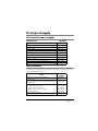
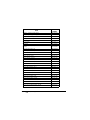
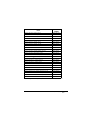


![BA_Nuvo_lite_GCE_2010-8400CE+_Rev_D_Feb_[...]](http://vs1.manualzilla.com/store/data/006727550_1-ea98e4c4e6e21d70cdd35784d97d652f-150x150.png)