1
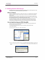
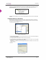
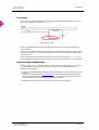
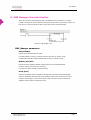
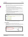
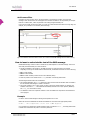
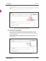
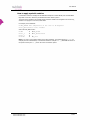
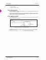
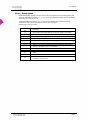
www.nubitek.com
Nubitek SMS Manager
User Manual
User Manual
Nubitek SMS Manager v1.3
User Manual.
Last updated: July 2008
© 2006 Nubitek industrial IT S.L.
All rights reserved.
The information in this document belongs to Nubitek industrial IT, S.L. (hereinafter referred to as NUBITEK). en adelante
NUBITEK). Authorization is granted by NUBITEK only fot the professional use of this document provided that the
following conditions are met: (1) indication that rights are reserved appears in all copies together with the present
authorization, (2) this document may be used for informative, personal and non-commercial purposes only, and may not
be copied or posted on any network computer or broadcast in any media, and (3) no modification is made to this
document. All other uses are specifically prohibited. NUBITEK makes no representations about the suitability of the
information contained in the documents and graphics published on this website for any specific purpose. All contets and
graphics are published “as is” and without warranties of any kind.
This documents may contain technical inaccuracies or typographical errors. Its contents are subject to periodic changes
and updates. NUBITEK may, at any given moment, make improvements and/or modifications to this document.
www.nubitek.com
2/29
User Manual
Introduction
The purpose of this manual is to explain how to install and use the Nubitek SMS Manager library to
manage the sending and receiving of SMS messages from a Siemens PLC S7-200 device.
Nubitek Industrial IT, S. L.
Nubitek Industrial IT is an industrial software development company that specialises in the integration of
automation systems with new information technologies.
Nubitek develops customised projects, as wells as producing and distributing applications for general use
with the Siemens PLC S7-200 device, such as Nubitek SMS Manager.
Nubitek’s corporate philosophy is to create software that is simple but powerful at the same time, thus
providing access to advanced industrial communication techniques via modem without the need to
undertake any development work.
Who is this document for?
S7-200 programmers who want to use the Nubitek SMS Manager library to integrate the sending and
receiving of SMS messages into their control projects.
Automation customers who are not experts in development for the S7-200 and who want to know
something specific about the Nubitek SMS Manager library.
How is this document organised?
Chapter 1 explains what Nubitek SMS Manager is and the advantages it offers to the user.
Chapters 3 to 6 provide the guidelines for using Nubitek SMS Manager: software installation, assigning
memory to the library, minimum requirements, equipment connections, and how to obtain the Nubitek
Key.
Chapters 7 to 10 provide detailed explanations of how to use the 3 functions of Nubitek SMS Manager for
sending and receiving SMS messages.
Chapter 11 contains the list of variables that the library produces in order to provide more information and
control to the user.
Chapter 12 explains how to access the CPU via Teleservice and how to perform the appropriate port
control.
Notations used in this guide
This document uses differences in print to identify the type of text, as shown in the following table:
Print
Use and examples
Italics
Menu options
Example: File -> Add or remove library
Bold
Important notifications for the reader.
Example: Attention
Monospaced
File names and directory paths.
Example: nubitek_sms_manager_v1.3.mwl
Text referring to program code.
Example: VB2000 “Alarm message.”
www.nubitek.com
3/29
User Manual
Contents
1. WHAT IS NUBITEK SMS MANAGER?
5
DESCRIPTION
FIELDS OF APPLICATION
FEATURES
5
5
5
2. QUICK START AND APPLICATION EXAMPLES
6
3. MINIMUM REQUIREMENTS
7
4. INSTALLING NUBITEK SMS MANAGER
8
WHAT IS A LIBRARY?
HOW TO INSTALL THE LIBRARY IN STEP7-MICROWIN
ASSIGNING MEMORY TO THE LIBRARY
5. HARDWARE: CONNECTIONS AND CONFIGURATION
8
8
9
10
REQUIRED EQUIPMENT
CONFIGURATION OF THE PC/PPI CABLE
CONNECTING THE EQUIPMENT
THE GSM MODEM
6. TEST MODE AND NUBITEK KEY
10
10
11
11
13
NUBITEK KEY
TEST MODE
HOW TO OBTAIN A NUBITEK KEY
7. PROGRAM FUNCTIONS: INTRODUCTION AND EXAMPLE
13
14
14
14
DESCRIPTION
A SIMPLE EXAMPLE
8. SMS MANAGER: THE MAIN FUNCTION
15
15
16
SMS_MANAGER PARAMETERS
9. SENDING SMS MESSAGES
16
17
SEND_SMS PARAMETERS
DEFINITION OF THE TEXTS AND DESTINATION TELEPHONE NUMBERS
SEND CONDITION
HOW TO INSERT A VALUE INTO THE TEXT OF THE SMS MESSAGE
THE BENEFITS OF USING SYMBOLS
10. RECEIVING SMS MESSAGES
17
17
18
19
20
22
RECEIVE_SMS PARAMETERS
FLEXIBLE RECOGNITION
OTHER CHARACTERISTICS
VALUE CAPTURE EXAMPLE
11. USER VARIABLES AREA
22
22
23
23
24
MAP OF THE USER VARIABLES AREA
ERROR / EVENT CODES
12. TELESERVICE AND MANAGEMENT OF PORT 0
24
26
27
HOW TO ACCESS THE CPU FROM STEP7-MICROWIN
REMOTE ACCESS USING TELESERVICE
LOCAL ACCESS VIA PORT 0
13. INTERNET SERVICE AND SUPPORT
27
27
28
29
NUBITEK SUPPORT
FAQ
www.nubitek.com
29
29
4/29
User Manual
1. What is Nubitek SMS Manager?
Description
Nubitek SMS Manager is a piece of control software that enables a Siemens PLC S7-200 device to be
combined with a GSM modem for sending and receiving SMS messages, integrating such SMS
communication into any control program in a simple, robust and secure manner.
Nubitek SMS Manager is a library that is ready to be added to the STEP7-MicroWIN programming
environment. It consists of 3 functions and their use is extremely simple: for each message that you wish
to send or receive, you simply need to add a segment to your control program.
Fields of application
Nubitek SMS Manager offers numerous application possibilities:
Receiving alarms or maintenance notifications to your mobile
Consulting the status of a remote station
Receiving production data
Commanding an installation remotely
Communicating by SMS between widely-distributed stations
And much more: contact Nubitek Support online and we will study the technical feasibility of your idea
Features
Total control of the GSM modem:
The application takes full control of everything related to the management of SMS messages: initialising
and configuring the GSM modem, sending outgoing SMS messages, receiving and analysing incoming SMS
messages, configuring and managing port communication, managing and recovering from incidents, etc.
Sending SMS messages:
Nubitek SMS Manager manages an unlimited number of outgoing SMS messages to multiple destination
telephones. In order to send an SMS message, all you need to do is indicate the basic parameters:
condition for activation, text of the message and destination telephone number(s).
The text of the SMS messages is freely defined in the Data Block, the insertion of variables into the
outgoing SMS messages is done automatically and the simultaneous alarms are managed with no losses
whatsoever.
Receiving SMS messages:
The recognition of incoming messages is performed by using keywords to identify the message, thus
providing great flexibility.
Nubitek SMS Manager analyses the incoming SMS messages and provides notification if it receives a
message that fulfils any of the defined parameters. It is even possible to capture numeric values
contained in SMS messages and store them in memory.
Teleservice:
Nubitek SMS Manager is compatible with Teleservice access, which can be activated locally or remotely by
means of a SMS message.
www.nubitek.com
5/29
User Manual
2. Quick start and application examples
The quick start manual is available for download from the Nubitek website, providing rapid contact with
the library from a mainly practical perspective.
The same page of the website also contains example projects that demonstrate and discuss in detail
exactly how Nubitek SMS Manager can be applied:
Tutorial example with all the basic SMS sending and receiving options, discussed and explained from
an educational perspective.
Examples of how to program the practical situations that are shown in the graphic animations on the
Nubitek website.
If you would like to receive a programming example that addresses a specific requirement, do not hesitate
to contact the Nubitek Support experts via the online support form or by calling to (34) 91 448 24 39.
www.nubitek.com
6/29
User Manual
3. Minimum requirements
CPU S7-200
Nubitek SMS Manager requires a latest generation (in other words, with reference xxx23, firmware 2.0)
CPU 224 or above. The following is a list of valid CPUs:
CPU
CPU
CPU
CPU
CPU
CPU
224 DC
224 AC
224XP DC
224XP AC
226 DC
226 AC
6ES7
6ES7
6ES7
6ES7
6ES7
6ES7
214
214
214
214
216
216
1AD23 0XB0
1BD23 0XB0
2AD23 0XB0
2BD23 0XB0
2AD23 0XB0
2BD23 0XB0
PC/PPI Cable
The PC/PPI cable that has been taken into consideration for the development of this application is the
Multimaestro PC/PPI cable with reference Siemens 6ES7 901 3CB30 0XA0. Therefore, this is the cable
that Nubitek recommends for connecting the CPU port to the GSM modem. Previous versions of the cable
or other PC/PPI adaptor models may be valid, however Nubitek can not guarantee correct communication
functions.
STEP7 MicroWIN
In order to install and use Nubitek SMS Manager, STEP7 MicroWIN 4.0 Service Pack 2, or a later
version, is required.
Program memory
The Nubitek SMS Manager library requires 6.0 Kbytes of the S7-200 program memory.
Variables memory
The Nubitek SMS Manager library reserves a total of 771 bytes of V memory in order to be able to
perform the internal management of its operation variables. Users should not use this area in their control
program.
www.nubitek.com
7/29
User Manual
4. Installing Nubitek SMS Manager
Nubitek SMS Manager is a library that manages the sending and receiving of SMS messages and is ready
for integration into the STEP7-MicroWIN programming environment.
What is a Library?
A library is a sub-program that performs a specific control function, in an independent and encapsulated
manner. For that reason, whoever uses a library does not need to worry about the internal operations
within the library.
Nubitek SMS Manager is an example of a library. Whoever uses it in their programs only needs to worry
about the usage parameters, such as the destination mobile number or the text. The library itself handles
the complicated task of managing the modem and sending the SMS message.
An important characteristic of a library is that it integrates itself into the development/programming
environment as an additional system function, which enables the programmer to use it in any of his
control programs, with significant time savings in terms of development and with increased reliability.
How to Install the Library in STEP7-MicroWIN
In order to be able to use the Nubitek SMS Manager tool, the library must firstly be installed into the
STEP7-MicroWIN programming environment.
1. Download the Nubitek SMS Manager library from the Nubitek website downloads page.
2. Open STEP7-MicroWIN
3. From the menu bar, click on File -> Add or remove library...
Figure 4.1: Add library
4. Click on Add, enter the directory where you downloaded Nubitek SMS Manager and select the
nubitek_sms_manager_v1.3.mwl file of the library. Once the library has been added, click on
Accept.
Figure 4.2: Select library
www.nubitek.com
8/29
User Manual
At this point, the Nubitek SMS Manager library should now be installed. This can be checked by accessing
the Libraries icon on the operations tree: the library folder should be displayed together with the 3
functions it consists of.
Figure 4.3: library at the operations tree
The library has been installed: you can use these 3 SMS management functions as if they were MicroWIN
functions.
Assigning Memory to the Library
When you start to use the library functions on your project, and always before loading or compiling it, a
memory range must be assigned to the library: its internal management requires 771 bytes of V memory,
the location of which can be defined by the user.
1. Click on File->Library memory:
Figure 4.4: Library memory
2. Select the Nubitek SMS Manager from the window that opens (if you have no other libraries installed, it
will be the only tab available).
3. Click Suggest address and MicroWIN will indicate a range of free memory.
4. If, for any reason, you would prefer to use a different range, all you need to do is click Suggest
address again or directly type in the desired start location.
Important: user variables of the control program should never be included in this memory range
used by the library.
5. Click OK
Figure 4.5: Library memory
www.nubitek.com
9/29
User Manual
5. Hardware: connections and configuration
Required Equipment
The following hardware elements are required for installation:
A SIMATIC S7-200 CPU (CPU224 v2.0 or higuer)
A GSM modem, with antenna and power supply. There are two options available:
Siemens TC35i Dual-Band EGSM900 / GSM1800 MHz
Siemens TC65 Quad band: GSM 850/900/1800/1900 MHz
A SIM card from any mobile telephone operator.
A PC/PPI Multimaster cable (ref. 6ES7 901 3CB30 0XA0, of Siemens)
A 9 pin, male-male Sub-D adapter.
Figure 5.1: Equipment required for SMS communication
Configuration of the PC/PPI cable
The Multimaestro cable has 8 micro-switches on the side of the casing that enables its mode of operation
to be configured.
In order for Nubitek SMS Manager to be able to communicate correctly with the GSM modem, the PC/PPI
cable must be configured in 9600 bauds mode, 10 bits, PPI/Freeport and remote connection: 01000110.
Micro-switch
Position
1
0
2
1
3
0
4
0
5
0
6
1
7
1
8
0
If a previous generation of PC/PPI cable is to be used, with only 6 micro-switches, the configuration is
000110. Nubitek does not guarantee the operation of all the Nubitek SMS Manager characteristics if this
type of cable is used, particularly the Teleservice functions.
NOTE: Each time the configuration of the micro-switches is changed, the power should be disconnected
from the PC/PPI cable in order for the new configuration to take effect. To do so, the cable must be
disconnected from the CPU S7-200 port. Once the lights on the side have turned off, it can be connected
again.
www.nubitek.com
10/29
User Manual
Connecting the Equipment
The following steps should be followed for connecting the equipment:
1. Insert the SIM card into the GSM modem. The slot to be used for this is labelled on the modem as SIM
and has a small yellow button to one side. Pressing this button with a pointed object will cause the tray
for placing the SIM card to eject. It is important to ensure that this tray is re-inserted correctly.
2. Insert the 9 pin male male adapter into the female serial port of the GSM modem.
3. Connect the antenna and the power source to the modem (to the RJ11 socket).
4. Configure the PC/PPI cable as indicated in the previous section.
5. Connect the end of the PC/PPI cable (female) to the modem using the 9 pin male male adapter. The
PPI (male) end must be connected to port 0 of the PLC S7-200.
Warning: the application will not function correctly if the PC/PPI cable is connected to port 1 of the
CPU.
6. Connect the power to both pieces of equipment. On some TC65 versions, the On/Off button needs to
be pressed for one second.
Figure 5.2: Connecting the equipment
The GSM modem
Port speed
It is usual for the modem to be factory packed with the port configured to 9600 bauds (TC35i) or to
115200 bauds (TC65). If this is the case, Nubitek SMS Manager will have no problem connecting to the
modem. The user will only need to connect it to the PC/PPI cable.
If the port is not configured to one of these speeds, Nubitek SMS Manager will be unable to connect to
the modem. If this happens, you can try to change the port speed manually: connect the modem to a
serial port of a PC and open the HyperTerminal, establish communication via the COM port at the
corresponding speed, and 8 data bits, no parity, 1 stop bit and no flow control. In order to verify that a
connection has been established, type AT (+ Enter). You should receive an OK response. The
www.nubitek.com
11/29
User Manual
command ‘AT+IPR=9600’ sets the modem speed to a level that will enable Nubitek SMS Manager to
communicate.
Coverage
Nubitek SMS Manager indicates the coverage measured by the modem and writes this level, in dBm, to a
location in the user variables range of the V memory. If the signal level is not sufficient to guarantee
operation, this will be indicated by the corresponding error message and the low coverage bit will be
activated. See the chapter regarding the user variables area for more details.
The level of coverage during installation can be quickly checked by using a normal mobile telephone.
Place the mobile at the location where the antenna is situated and observe the coverage indicator on the
display.
TC35i modem
The TC35i modem will switch on automatically when it receives power. The SIM card should be inserted
or removed when the power is disconnected.
The modem indicator light has three different statuses:
Off: the modem is not receiving power or has received an instruction to switch off.
Regular flashing (1 second on and 1 second off): the modem is switched on and active but has not yet
established a link to the mobile telephony operator (equivalent to having a mobile telephone switched
on but with no PIN entered).
Rapid flash every 2 seconds: a link has been established with the mobile telephony operator, this
happens just after entering the PIN on the SIM card. This is the mode in which the modem should
operate and should be achieved a few seconds after activating the installation. If this does not happen,
check the error code by referring to the chapter regarding the user variables area.
TC65 modem
Version 2.0 of the TC65 behaves in exactly the same way as the TC35i.
Version 1.4 of the TC65, also compatible with Nubitek SMS Manager, behaves slightly differently. The
indicator light is used to display the communication status, meaning that it flashes when an SMS message
is being sent or received. In addition, the modem does not switch on automatically: once the power
source and the ports have been connected, the On/Off button must be pressed for approximately one
second.
www.nubitek.com
12/29
User Manual
6. Test mode and Nubitek key
The Nubitek SMS Manager library:
can be downloaded and distributed for free and can be freely installed into STEP7-MicroWIN
requires a key to run successfully in S7-200
can be run in test mode in order to try it out for free
Nubitek Key
This key will enable Nubitek SMS Manager to function during an unlimited period of time. Without a
correct password the program shuts down the modem and freezes.
The key must be entered in the PLC program itself as parameter Nubitek_KEY of the SMS_Manager
function.
Figure 6.1: Nubitek key in the control program
IMPORTANT: the Nubitek key is associated to the GSM modem used during installation, in other words:
In order to obtain a key, the IMEI of the GSM modem that is going to be used must be declared.
The key enables Nubitek SMS Manager to function solely and exclusively with that modem and no
other.
¿What is the IMEI?
The IMEI is a unique identification code that each GSM hardware device has (modems, mobiles, etc.).
It is a 15 digit number that indicates the manufacturer, country and serial number: it is unique in each
modem.
On Siemens modems, the IMEI is indicated on the label on the back, beneath the bar code.
Figure 6.2: Back of the TC35i modem and location of the IMEI
www.nubitek.com
13/29
User Manual
Test mode
The test mode is configured by indicated a value of zero in the field where the Nubitek key is located, in
other words, creating the parameter Nubitek_Key = 0.
Figure 6.3: Test mode
The test mode enables full use of Nubitek SMS Manager and enables as many tests or client demos as
may be necessary.
There is only one limitation: during test mode, SMS management freezes approximately every 5 hours and
the modem switches off. In order to continue the tests, all you need to do is switch on the modem again
and restart the CPU.
If you would like to know when a test period is going to come to an end, the field Minutes_LEFT in
the user variables area displays the number of minutes remaining until the end of the current test period.
How to obtain a Nubitek Key
In order to obtain a key, it is essential to indicate the IMEI number of the GSM modem you are going to
use. The application will only operate if the S7-200 is combined with the GSM modem declared.
Nubitek key can be obtained:
Through an automation equipment distributor, indicating the IMEI of the modem with which it is going
to operate.
Directly from the Nubitek website, www.nubitek.com, by purchasing a Nubitek SMS Manager licence
online and obtaining the final usage key. The FAQ section of the website contains further information
about the purchase process and the management of licences and keys.
Calling Nubitek at (34) 91 448 24 39 and asking for a Nubitek_Key for your system.
www.nubitek.com
14/29
User Manual
7. Program functions: introduction and example
Nubitek SMS Manager consists of 3 functions that are simple to use and easily integrated into any control
program.
Description
SMS_Manager performs all the general management procedures of the application, as well as port
control and modem initialisation. It must be called once during all program cycles, at the start.
Send_SMS is used once for each of the SMS messages that need to be sent. It is called with the
activation or sending condition and it requires the text and the destination mobile numbers. There is
no limit to the number of different SMS messages that can be sent.
Receive_SMS is used to define the keywords that the control program must recognise within the
incoming SMS messages. The function analyses the received SMS messages and activates an output bit
when they are found. There is no limit to the number of different messages that can be recognised.
A simple example
In this simple example, the 3 functions are called from the main program block.
Figure 7.1: Simple example of Nubitek SMS Manager in use
Segment 1: SMS_Manager configures the modem and performs the full control of the SMS
application. It only requires the PIN of the SIM card. In test mode Nubitek key = 0. When it is
ready it sets the output Q0.0.
Segment 2: Send_SMS, when the rising edge of Alarm_Stop happens, sends an alarm SMS
message to David's mobile. Both message text and phone number are defined in the Data Block.
Segment 3: Receive_SMS defines the keywords for the activation of the process. When the SMS
message "active proccess" is received the Start_Production bit is activated.
www.nubitek.com
15/29
User Manual
8. SMS Manager: the main function
This is the main control and management block of the application and is essential for it to operate.
It needs to be called just once and executed in all program cycles, before any other library function. The
best option is to make the call with the SM0.0 contact at the start of the OB1 Main Block.
Figure 8.1: SMS_Manager in use
SMS_Manager parameters
PIN: (STRING)
PIN code of the SIM card within the modem.
It is written directly as a string of 4 characters at the function call. For example, “2244”.
If a SIM card is used with the PIN code deactivated, the string is entered as empty “”.
Nubitek_KEY (INT)
Numeric key that is supplied by Nubitek so that the library can be executed indefinitely.
In order to operate in trial mode, enter a value of 0.
It is written as a integer variable (no quotation marks).
Ready (Bool)
Output bit that indicates that the application is OK and ready to send and receive SMS messages.
During the initialisation phase and under normal conditions, it takes about 30 seconds to be set to 1.
It may be useful to apply it to any S7-200’s output in order to be able to easily note whether the
application and the modem are operating correctly.
www.nubitek.com
16/29
User Manual
9. Sending SMS messages
The Send_SMS function sends an SMS message to one or two destination mobile telephones. It is used
once for each different SMS message that you wish to send.
Figure 9.1: Send_SMS function -> Sending an SMS message to two mobile telephones
Send_SMS parameters
SMS (Pointer to String)
Text of the SMS message that has been defined in the Data Block as a String variable. The start point of
the text is indicated in pointer mode using the “&” pointer notation.
For example, to send the SMS message defined as VB3000 “ALARM: machine stopped due
to motor failure”, &VB3000 is indicated.
It is advised to make use of symbolic notation in order to facilitate the compression and maintenance of
the program.
Tel_1 (Pointer to String)
Destination telephone number for the SMS message that has been defined in the Data Block as a String
variable. The start point is indicated in pointer mode using the “&” pointer notation.
For example, for the telephone defined as VB3100 “+34600123456”, &VB3100 is indicated.
It is advised to make use of symbolic notation in order to facilitate the compression and maintenance of
the program.
Tel_2 (Pointer to String)
Additional destination telephone number. It is defined in the same way as Tel_1 and enables the SMS
message to be sent to a second mobile number during the same operation.
If you do not wish to specify a second telephone, a value of 0 must be entered.
Value: (Pointer)
Pointer to the position of the numeric variable that you wish to include in the SMS text automatically. This
can be an INT, DINT or REAL value.
If you do not wish to insert any variables in the SMS text, the Value parameter will not be used and must
be entered as 0.
Definition of the texts and destination telephone numbers
Both the SMS text and the destination telephone numbers are comfortably defined in the Data Block as
String variables. Important: double quotation marks must be used.
For example:
VB3000 “ALARM: machine stopped due to motor failure”
www.nubitek.com
17/29
User Manual
VB3100 “+34600123456”
Nubitek SMS Manager has no limitation on the number of SMS messages and destination telephone
numbers. It admits as many SMS messages and different telephone numbers as can be stored by the Data
Block.
The text of the SMS messages are defined in a flexible manner:
They can be as long as is necessary, provided that they do not exceed 160 characters.
Any text is admitted, however certain regional or uncommon characters may not be accepted by the
modem or GSM operator. It is recommended to check that such characters are sent correctly.
Nubitek SMS Manager enables numeric variables to be inserted into the text easily and automatically.
How to do this is explained further in the relevant section of this chapter.
The destination telephone numbers:
Must be defined using the ‘+’ symbol and the country code. For example, in the case of Spain (prefix
34), telephone number 600123456 must be indicated as +34600123456.
Telephone numbers from different countries can be used together in the same project provided that
they are indicated with their corresponding prefixes.
Important: The country prefix should not be included for certain countries and operators. If the texts
produce a failure when sending the SMS (error code 32), it is advised to try changing the definition of
the telephone number.
Figure 9.2: Definition of the texts and telephone numbers in the Data Block
Send condition
The Send_SMS function must be called when the SMS send condition is fulfilled.
Important: Send_SMS need be executed only once, in other words, one single program cycle. In order
to avoid the SMS message being sent repeatedly, it is advised to indicate the activation condition followed
by a rising edge.
Note: the Send_SMS function ignored the send instructions when the Ready bit is not active.
Figure 9.3: The call to Send_SMS must be made using an edge
www.nubitek.com
18/29
User Manual
Anti-bounce filter
A situation can arise in which, due to the bounce effect of the activation condition, the same SMS
message is sent several times. This will happen if the activation condition is not fully reliable, for example
because of a bad contact, a lack of hysteresis in the analogue signal threshold, etc.
If you wish to include an anti-bounce filter, you must use a disconnection timer before the rising edge. For
example, for a protection of 10 minutes, do the following:
Figure 9.4: Effective anti-bounce filter in order not to receive several SMS message from the same warning
How to insert a value into the text of the SMS message
Nubitek SMS Manager is able to insert a variable at any desired position of an SMS message. This can be
done easily and automatically. It is done as follows:
1. Include an identifier at the position in the SMS text where you want the value to be inserted.
Depending on the type of variable and the desired format, the identifier should be one of the following:
&I for a INT variable
&D for a DINT variable
&R for a REAL variable (it will be shown to three decimal places)
2. Place the pointer to the variable in the Value parameter of the Send_SMS function.
The following should be taken into consideration:
The variable indicated in the Value parameter must be coherent with the identifier that is included in
the text. Nubitek SMS Manager is unable to check this.
The pointer notation is “&”, in other words, in order to insert the variable VW4000, for example, the
indicator must be &VW4000. MicroWIN will automatically translate it into a byte position (&VB4000)
but Send_SMS will function correctly.
It is advised to make use of symbolic notation in order to facilitate the compression and maintenance
of the program.
Example
In order to send an SMS message containing the temperature of an oven:
Define the text in the Data Block and include the identifier for the value at the appropriate position:
VB1000 “The temperature of the oven is &R degrees”
If, for example, the temperature variable in REAL format is contained in VD2500, the Send_SMS function
is called and is informed of the pointer in the Value parameter:
www.nubitek.com
19/29
User Manual
Value = &VD2500
If the temperature is such that VD2500 equals 113.6324 when the SMS message is sent, the text received
will be:
“The temperature of the oven is 113.632 degrees”
Figure 9.6: Insertion of variables into an SMS message
The benefits of using symbols
The use of symbols to name program variables is always beneficial in any application. For an SMS
management program, it can spectacularly improve the legibility and maintenance of the program.
Every message, every telephone number, every activation condition and every variable to be inserted can
have its own symbolic name.
Compare the example in Figure 9.6 with the example in Figure 9.7. Of the two ways to send a
maintenance alarm when an alarm is activated due to excess oven temperature, the second is obviously
the clearer of the two.
Figure 9.7: Insertion of variables in an SMS message using symbolic notation
www.nubitek.com
20/29
User Manual
How to apply symbolic notation
It is advised to name the message and the destination telephone numbers directly from the Data Block.
Right click on the line in which they are defined and select “Define symbol…”.
The names of the variables to be inserted and the activation conditions are assigned in the normal way,
whether in the program or from the symbols table.
For example, in the Data Block:
SMS_ALARM “The temperature of the oven is &R degrees”
Tel_Maintenance “+34600123456”
And in the Send_SMS function:
SMS
Tel_1
Tel_2
Value
&SMS_Alarm
&Tel_Maintenance
0
&T_Oven
Note: if you wish to use symbolic notation in the Value parameter, the symbol pointer (&T_Oven, for
example) must be entered directly. If the absolute method is used (&VD2500), MicroWIN will convert it
into pointer format (&VB2500) and it will not be converted to symbol.
www.nubitek.com
21/29
User Manual
10. Receiving SMS messages
The Receive_SMS function recognises an incoming SMS depending on one or two keywords. It also
permits the automatic capture of a numeric value contained in the text of the message.
Receive_SMS must be used once for each type of different message that you wish to recognise. There is
no limit to the number of times it can be used.
The function must be called during all cycles, using the contact SM0.0.
Figure 10.1: Recognition of incoming SMS message
Receive_SMS parameters
TXT_1 and TXT_2: (String)
Keywords to be recognised in the incoming message.
They are entered directly as strings at the entrance (for example, “activate” and “irrigatation”).
If you only wish to define one keyword, TXT_2 must be left blank and the string must be empty “”.
SMS_Rcv: (Bool)
Output bit that is activated when an SMS message is received containing the keywords.
Important: SMS_Rcv is only activated during one single program cycle. It subsequently returns to 0.
Value: (Real)
It collects the numeric value that has been captured from the incoming message and saves it in REAL
format, even if it is received in the SMS as a whole number.
It is an in/out parameter. Therefore, the value remains in the variable after having received the message.
The use of this parameter is optional. If you are not going to use it, enter any unused position. The same
one can be used for all the calls that do not use the Value parameter.
Flexible recognition
Receive_SMS recognises SMS messages in a robust and flexible manner, freeing the user from having
to remember strict formats.
It is possible for there to be more text in addition to the keywords.
It locates the keywords in any order and position.
It does not differentiate between upper and lower case letters (within the standard international
alphabet)
It captures the numeric value, whether a whole number or with decimal places, from any position in
the message.
In the example shown in Figure 10.1, the keywords “Activate” and “irrigation” are defined. Any of the
following messages will be recognised:
“activate irrigation”
“ACTIVATE IRRIGATION”
www.nubitek.com
22/29
User Manual
“irrigation activate”
“Activate the irrigation system.”
Other characteristics
If an SMS message fits two different models, the SMS_Rcv exit will only be activated for the Receive_SMS
function that is first in the program.
If you wish to save program memory, the keywords can be defined in the Data Block and just the memory
positions (VB3000 and VB3020, for example) can be entered as the TXT_1 and TXT_2 parameters. Use
symbolic notation and you will not lose program legibility.
Value capture example
In the example shown below, Receive_SMS is configured to receive the irrigation activation instruction
and the period of time to remain active.
Figure 10.2: value capture from incoming messages
For example, when receiving the message “activate the irrigation 35 minutes”, the
system will activate the Start_Irrigation bit (it is set to 1 for one program cycle) and will enter
the value 35.0 in the variable Irrigation_Time (in REAL format and permanently).
www.nubitek.com
23/29
User Manual
11. User variables area
The user variables area holds a set of variables that the Nubitek SMS Manager application uses to provide
information to the user, or to receive instructions for a specific purpose. It can be compared to the SM
area for special marks of the S7-200.
The area is stored in the V memory, at the start of the area reserved for the library. The exact position of
each variable can be consulted on the table of symbols, on the tab with the name of the library (once
memory has been assigned to the library).
These variables can be integrated into the control program for advanced use. However, although they
appear in the table of symbols with a symbolic name, they can only be used in the application with an
absolute address (this is a rule of Step7-MicroWIN, due to the fact that they are internal variables of a
library).
Figure 11.1: User variables area that can be found in the table of symbols
Map of the user variables area
Assuming that the area assigned to the library starts with VBn, it is:
SMS_Ready (Read, Bool, VBn + 0.0)
Indicates that the application is ready to send and receive SMS messages. During the initialisation stage,
under normal conditions, it takes about 30 seconds to be set to 1. It is equivalent to the SMS_Ready
output of the main function.
PPI_Mode (Read, Bool, VBn + 0.1)
Indicates that port 0 of the CPU of the S7-200 is in PPI mode.
In this mode, a connection can be made from Step7-MicroWIN, whether via Teleservice or directly, by
disconnecting the modem and connecting the programmer to the port.
In this mode, SMS management is temporarily disabled.
PPI_Request (Write, Bool, VBn + 0.2)
Bit for requesting the application to change port 0 to PPI mode.
Important: No direct changes should be made to the SMB30 control field of port 0. By activating this bit,
the application makes the change in a controlled manner.
Connection can be made to a system input in order to facilitate access for the programmer without
needing to put the CPU in STOP.
It is only necessary to activate the bit for one cycle. The application will set it to 0 again when the change
to PPI mode has been made.
www.nubitek.com
24/29
User Manual
END_Teleservice (Write, Bool, VBn + 0.3)
Bit for requesting a return to normal operation mode from PPI mode. This is used to indicate to the
application that the maintenance tasks have been completed and that it can make use of the port and the
modem again.
By entering a value of 1 in this variable, a period of 90 seconds begins during which the bit will be
intermittent. Upon completion, the change to normal mode occurs.
Low_Signal_Level (Read, Bool, VBn + 0.4)
Indicates that the coverage level measurement reflects a low signal level for the operator, below the
threshold that ensures correct communication.
The measured signal value, in dBm, is shown in the variable Signal_Level.
Measurement is not performed continuously, only when the application is restarted.
FULL_Licence (Read, Bool, VBn + 0.5)
Indicates that a Nubitek key is being used and that the application will function permanently.
TEST_mode (Read, Bool, VBn + 0.6)
Indicates that the application is functioning in test mode. The application will freeze approximately every 5
hours.
The number of minutes remaining until the next freeze can be consulted in the variable
Minutes_LEFT.
ERROR (Read, Bool, VBn + 0.7)
Indicates that an error or event has occurred. This bit is set to 1 for only one program cycle.
The code representing the type of error or event that has occurred is stored in the field Last_ERROR.
Last_ERROR (Read, INT, VBn + 2.0)
Code representing the last error or event that has occurred, which remains the same until a new error or
event occurs.
The meaning of each error code can be consulted in the following section of this chapter.
SMS_Counter (Read, INT, VBn + 4.0)
Sent SMS message counter for the application.
This can be used to count the outgoing SMS messages in such a way that the recipient can know if the
messages are being received correctly and in full.
Signal_Level (Read, INT, VBn + 6.0)
Measured value of the GSM signal, in dBm.
A value of over -91 dBm is sufficient. Less than -95 dBm is very deficient.
Minutes_LEFT (Read, INT, VBn + 8.0)
This is related to the test mode. In normal mode, this is set to 0.
It is a decreasing counter that indicates the number of minutes remaining until the next time the
application will freeze.
Last_Value_RCV (Read, REAL, VBn + 10.0)
Contains the last value that was captured by a Receive_SMS function. This same value is also provided
by the same function with the parameter Value.
www.nubitek.com
25/29
User Manual
Error / Event codes
Nubitek SMS Manager provides a series of codes to help the programmer during the development stage
and during maintenance. The field Last_ERROR in the user variables area stores the code representing
the last error or event that occurred.
This field is updated every time the ERROR bit of the user variables area is activated and can be
consulted from the control program itself in order for action to be taken.
The following is a list of the codes:
Error / Event
code
Description
12
13
The modem is not responding to the command sent by the PLC: possible
disconnection of the PC/PPI cable or loss of power supply to the modem.
Unknown error: the response from the modem is not recognised by the PLC.
The modem is indicating an ERROR: possible parameterisation fault.
14
The PIN for the SIM card is incorrect.
15
There is insufficient coverage to establish guaranteed communication.
23
Test mode: the modem has been disconnected. Restart the CPU and the
modem for an additional 5 hours of operation.
24
Incorrect Nubitek key: modem switched off.
31
An SMS message has been received that does not correspond to any defined
model.
32
It has not been possible to send the SMS correctly: reason unknown.
33
The SMS exit buffer is full (up to 7 SMS allowed in the queue). The last SMS
message has not been sent.
11
www.nubitek.com
26/29
User Manual
12. Teleservice and management of port 0
Nubitek SMS Manager uses port 0 of the S7-200 CPU for connecting to the GSM modem. The application
handles all port configurations and also uploads the parameters to the modem for Teleservice support
from a remote PC.
Important: port 0 must be exclusively reserved for communication with the GSM modem, you should
never try to create a network with additional elements.
Important: the programmer should never try to control the port in any way that is external to the
application. This may cause conflicts and cause SMS management not to operate.
How to access the CPU from STEP7-MicroWIN
The normal operation of the port under Nubitek SMS Manager control is in freeport mode. This is
necessary to control the GSM modem and the SMS application. This mode is incompatible with Step7MicroWIN access via the port, whether directly or via Teleservice.
In order to access the CPU from Step7-MicroWIN via port 0, it is necessary for the port to be configured in
PPI mode.
There are 4 ways to access the CPU:
Use a CPU with two ports and connect via port 1 in PPI mode.
Put the CPU in STOP: this automatically sets the ports to PPI mode.
Locally request Nubitek SMS Manager to temporarily suspend SMS management and set the port to
PPI mode in a controlled manner. This enables the modem cable to be disconnected from the port and
provides access with the programmer. For more details, refer to the relevant section of this chapter.
Request the application, remotely by using an SMS, to configure itself to enable Teleservice access via
the GSM modem. For more details, refer to the relevant section of this chapter.
Remote access using Teleservice
The Step7-MicroWIN modems wizard is used to configure the remote and local modems.
Configure the local modem in the normal way.
It is not necessary to configure the remote modem, the application does it all automatically.
The following steps should be followed for undertaking remote Teleservice access:
1. Send an SMS message to the telephone number of the remote station with the word
‘teleservice’. This will make the station permit Teleservice access.
2. Wait a reasonable amount of time, 1 minute for example, and proceed with the Teleservice access
from Step7-MicroWIN as you would do normally.
3. Once you send the SMS message, you have a period of 2 hours access. When this period ends, the
station will automatically return to SMS management mode. If you are going to need more time,
consult Nubitek Support.
4. When you have finished the maintenance tasks, you can hang up the call and leave the station to
return to normal operation mode itself when the two hour time period comes to an end.
If you do not want the station to wait the normal period of 2 hours but to return to operation mode as
soon as possible:
Stay online when you have finished the maintenance task.
Open the table of symbols associated to the library.
Find the position assigned to the END_Teleservice bit in the user variables area.
Open the status table and put it online.
Display the value of the END_Teleservice bit, which will be set to FALSE (MicroWIN forces
absolute addressing for this variable because it belongs to a library).
Enter the value TRUE for the END_Teleservice bit. Do not force it, just enter it for one cycle. You
will see that it becomes intermittent.
You have 90 seconds to disconnect, after which the station will return to SMS management mode.
www.nubitek.com
27/29
User Manual
Local access via port 0
The user variables area provides the programmer with the PPI_Request bit so that Nubitek SMS
Manager can change the port to PPI in a controlled manner.
The programmer can activate the PPI_Request bit using a button or operator panel. This should only
be done during one program cycle. The bit will remain active until the mode change is complete:
subsequently, PPI_Request will be set to 0 and PPI_Mode will be set to 1.
Once PPI_Mode is set to 1, you have 2 hours of free PPI access via port 0, after which it will
automatically return to SMS management mode. During this time, the SMS application will be suspended.
If you need more time, consult Nubitek Support.
In order to return to SMS management mode before the period of 2 hours comes to an end, you must act
on the END_Teleservice bit during one program cycle. The END_Teleservice bit will become
intermittent for 90 seconds, after which the port will be changed, END_Teleservice will cease to be
intermittent, PPI_Mode will be deactivated and, a few seconds later, SMS_Ready will be activated
again.
www.nubitek.com
28/29
User Manual
13. Internet service and support
Nubitek Support
Nubitek’s technical support service is comprised of extremely highly-qualified experts. We can help you
during any stage of your IT Automation project in order for it to be completed successfully:
Initial stage: tell us your idea: we will study it and tell you how you can use our communications
libraries to cover your needs.
Development stage: any question related to the use of Nubitek Solutions’ libraries or what to do in
order to obtain the expected result will be resolved by our experts.
Activation: it is also essential to receive good support services during this stage. We will answer your
questions as soon as possible.
Nubitek’s website provides code examples, technical manuals and contact forms to help your development
projects. If you would prefer a customised project, Nubitek Projects can develop one for you.
If you would like to receive technical support by phone, please call Nubitek at (34) 91 448 24 39.
FAQ
Nubitek’s website also contains the answers to numerous questions related to our products, licence
management or simply knowing what to do when a fault occurs with a modem for which you have already
obtained a password.
Answers to these questions and more can be found in the More Technical Information section of each
product and also on the FAQ page of our website.
www.nubitek.com
29/29