1
UltraDoser Injector System
with AB1500 Controller
USER MANUAL
Cryotech International, Inc.
745-B Camden Avenue
Campbell, CA 95008
(408) 371-3303 Phone
(408) 371-3320 Fax
www.cryotechinternational.com
Table of Contents:
General Information ……………………………………………………………………
-
3
Safety ………………………………………………………………………………………………
Principles of LN2 Dosing …………………………………………………………………………
Unpacking the injector ……………………………………………………………………………
Unpacking checklist ………………………………………………………………………………
Product Warranty …………………………………………………………………………………
3
3
4
4
5
Product Specifications ………………………………………………………..………
6
System Components ………………………………………………………………….
8
System Installation ……………………………………………………………………
11
Accessories ……………………………………………………………………………
14
Electronic Controller …………………………………………………………….…… 16
-
-
Components ……………………………………………………………………………………..
Start up Procedure ………………………………………………………………………………
Controller Screens…………………………………………………………………………………
- Main………………………………………………………………………………………
- Administration……………………………………………………………………………
- Access and Passwords……………………………………………………….
- System Setup…………………………………………………………………………….
- Dispense Setup………………………………………………………………………….
- System Functions ………………………………………………………………………
- Maintenance and Factory Setup……………………………………………………….
- Alarms ……………………………………………………………………………………
Controller Setup and Operation………………………………………………………………….
- System Setup……………………………………………………………………………..
- Synchronizing the Dose with the Container…………………………………………..
- Recipes……………………………………………………………………………………
16
17
17
17
18
20
21
21
23
25
25
27
27
29
34
Daily Operations ……………………………………………………………..………… 38
Maintenance ………………………………………………………………..…………… 39
-
Routine ………………………………………………………………………..……………… 39
Preventative …………………………………………………………………...……………… 40
Trouble Shooting ……………………………………………………………,………… 41
Service Parts…………………………………………………………………………….. 43
Replacement Parts ………………………………………………………….,………… 44
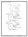
Sensor Positioning …………………………………………………………. Appendix A
-
Two Sensor
Three Sensor
Two Sensor and Encoder
Wiring Diagram ……………………………………………………………… Appendix B
File:UltraDoser with AB1500 controller
Page 2 of 46
Document #15905/040207
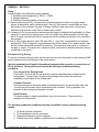
GENERAL – SECTION I
Safety
Liquid nitrogen (LN2) has three primary hazards:
1. Extremely cold temperature {(-320 F), (-196C)}
2. Oxygen depletion
3. Potential of bursting sealed environments
1. When working around LN2, use personal protective equipment such as cryogenic rated
gloves, a face shield, and a chemical apron. Any LN2 that comes in contact with skin may
cause burns. Non-insulated LN2 pipe or fittings, such as a tank connection, will become
extremely cold and can cause flesh to freeze upon contact.
2. A release of LN2 into an enclosed environment will begin to displace the breathable air. When
using LN2 in an enclosed environment, such as a small room where portable LN2 tanks are
filled, Cryotech recommends that an oxygen monitor be installed and proper room ventilation
be provided.
3. Due to LN2’s high expansion rate (700 parts GN2 to 1 part LN2), the possibility of a pressure
burst exists. If LN2 is trapped in a pipe between two closed valves or in a sealed vessel, then
the LN2 inside will expand and build up pressure. This expansion may result in a rupture of
the pipe or vessel. To prevent this, a pressure relief valve must be installed wherever there is
a potential to trap liquid.
Principles of LN2 Dosing
To ensure consistent dosing results, an accurate dose must be delivered to each container AND
each container must be processed in the same manner.
Injection systems from Cryotech International guarantee that a precise, accurate dose of
LN2 is delivered. The injection series meets the following fundamental dosing
conditions.
Pure Liquid at the Dosing Head
Pure liquid (i.e. liquid with no gas pockets) must be instantaneously available at the
dosing head. Cryotech has a unique internal design that ensures the continual
availability of pure liquid at the dosing head.
Constant Pressure
Constant pressure at the dosing head is critical requirement for reproducible dose size.
The unit has a float valve that is monitored by the controller. During operation, the
pressure at the dosing head remains constant.
Dose Duration
The dose duration is tightly controlled by the unit’s electronics. Dose duration is
measured in milliseconds.
The following production conditions must be controlled to ensure consistent dosing
results:
1.
2.
3.
4.
Fill levels must be consistent.
Fill temperatures must be consistent.
Capping techniques must be consistent.
Product may not be spilled or splashed out of containers following dose
File:UltraDoser with AB1500 controller
Page 3 of 46
Document #15905/040207
Unpacking the Injector
The injector will arrive in a specially designed shipping crate. If it is planned to have a mobile
injector system or if the unit is being leased the shipping crate should be stored for future use.
It is important that the crate be inspected before unpacking the injector. All exterior parts of the
crate should be free from dents and/or other damage. If shipping damage is noted it should be
reported to the carrier immediately.
While unpacking the crate, all contents should be inspected. All pieces should be free from
dents and/or other damage. If there is a discrepancy between the packing list and the contents
in the shipping crate, contact Cryotech immediately at (408) 371-3303.
Injector Unpacking Checklist:
1. Injector reservoir/arm unit with bracket
2. Controller
3. Speed sensor and speed sensor extension cable
4. Container sensor
5. 12’ Extension for distribution cable
6. Two (2) 12’ Polyurethane tubes – labeled as tube 03 and tube 04
7. Two spare compression fittings
8. 10’ CryotechFlex hose (for portable systems)
9. Three dosing nozzles – one installed, two additional and one nozzle installation tool
10. Stainless steel support stand and other accessories (if ordered)
File:UltraDoser with AB1500 controller
Page 4 of 46
Document #15905/040207
Warranty: Cryotech International
Cryotech International warrants that each of its products will be free from defects in material and
workmanship, in the normal service for which the product was manufactured, for a period of one
year from the date of shipment to the original purchaser. The following products carry an
additional two years of warranty: StatiFlex and DynaFlex vacuum insulated piping. To make a
claim under this warranty, the purchaser must: 1) give Cryotech written notice within ten (10)
days after the discovery of a claimed defect, 2) immediately discontinue the use of the product,
and 3) return such product freight prepaid to the location specified by Cryotech for evaluation to
validate the warranty claim. If the claimed defect is confirmed by Cryotech’s inspection,
Cryotech will, at its option and as the purchaser’s sole remedy, repair or replace such product or
any component part thereof or refund the original purchase price. This warranty is voided by
alterations or by repairs of others. Cryotech shall not be liable under this warranty, or otherwise,
for defects or accidents caused by the purchaser’s negligence, abuse/misuse or modifications to
the product or for failures due to corrosion, fire, heat or the effects of normal wear. Proper
installation by the purchaser of normal maintenance parts supplied by Cryotech shall not
constitute modifications to the product. Any related components or other equipment
manufactured by others which may be sold with Cryotech products are not covered by this
warranty but would carry any applicable original equipment manufacturer’s warranty.
This warranty is in lieu of any other warranties, express or implied, including any implied
warranty of merchantability or fitness for a particular purpose. The remedies set forth herein are
exclusive. Cryotech shall not be liable for any consequential, special or incidental damages
resulting from the delivery, use or failure of the product or from any other cause whatsoever. By
accepting delivery of the product sold hereunder, the purchaser acknowledges that this
limitation of remedies is reasonable and enforceable. In no event shall Cryotech’s liability
exceed the value of the product sold.
File:UltraDoser with AB1500 controller
Page 5 of 46
Document #15905/040207
SPECIFICATIONS – SECTION II
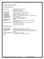
Product Specifications
Dimensions
Dosing Head:
Total Weight
w/electronics:
Dosing Range:
Dosing Accuracy:
Timing Range:
Control Voltage
Materials:
Crate Dimensions:
Reservoir height: 29” (737 mm)
Hexagonal: 6” (152 mm)
Arm reach : 12” (305 mm)
2.0” (51 mm) wide x 9” (229 mm) high
UltraDoser Injector - 32 pounds (14.5 kg)
Controller - 22.5 pounds (10.2 kg)
Minimum: 0.5 grams/second Maximum: 12 grams/second
+/- 5% of dose value
Effective Minimum: 15 milliseconds
Maximum: 1000 milliseconds
24 VDC
Stainless steel construction. Built to food and beverage
industry standards.
90”L x 32”W x 22” H (2286 mm x 813mm x 559 mm)
225 lbs with stand (102 kg)
140 lbs without stand (64 kg)
Utility Requirements
Electrical Supply:
Liquid Nitrogen
Source:
Gaseous Nitrogen or
CDA
100-240 VAC Input, 150VA MAX., 50-60HZ
Maximum 22 psig for portable system, 100 psig for plant
system with phase separator. Maximum flow rate 15 gallons
per hour
60 to 100 psi (4.1 to 6.9 bar)
10 SCFH gas per 100 containers per minute
File:UltraDoser with AB1500 controller
Page 6 of 46
Document #15905/040207
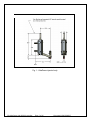
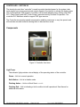
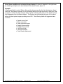
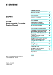
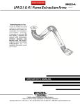
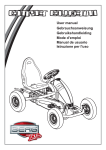
Fig. 1: UltraDoser injector body
File:UltraDoser with AB1500 controller
Page 7 of 46
Document #15905/040207
SYSTEM COMPONENTS – SECTION III
LN2 Reservoir
The stainless steel vacuum insulated reservoir provides a ready supply of LN2 for dosing
operations.
Distribution Block
This electrical connection “block” houses the connectors and wiring interface between the
operating parts of the Injector unit and the controller. There are five Eurofast
connections on this distribution block labeled D1 – D5 as described below. The
distribution block connects to the control box via a 36” cable assembly.
Vent Heater Cable Connection, D-1
Labeled D-1 on the distribution block this connector provides +24VDC power to the vent
heater. A green light on the cable connector indicates that power is being made available
to the vent heater.
Dosing Head Heater Cable Connection, D-2
Labeled D-2 on the distribution block this connector provides +24VDC power to the
dosing head heater. A green light on the cable connector indicates that power is being
made available to the dosing head heater.
Timing/Container Sensor Cable Connection, D-3
Labeled D-3 on the distribution block this connector provides +24VDC power to the
timing/container sensor and indicates sensor activity. A green light on the cable
connector indicates that power is being supplied to the sensor. A yellow light will appear
whenever a container and/or a container pulse is detected.
Solenoid Valve Cable Connection, D-4
Labeled D-4 on the distribution block this connector provides +24VDC power to the
solenoid valve assembly. A green light on the cable connector indicates that power is
being supplied to the solenoid valve. A yellow light will appear whenever the solenoid
valve has been activated.
Confirm Sensor Cable Connection, D-5
Labeled D-5 on the distribution block this connector provides +24VDC power to the
confirm sensor assembly. A green light on the cable connector indicates that power is
being supplied to the confirm sensor. A yellow light will appear whenever the pneumatic
cylinder has lifted the valve stem. A similar yellow indicator will also be illuminated on the
sensor body. This light mirrors the yellow light activity on the cable and confirms the lifting
of the valve stem.
Bayonet Connection
This bayonet connection allows the CryotechFlex hose to connect to the injector unit.
Bayonets are vacuum insulated and provide a warm, frost-free connection.
File:UltraDoser with AB1500 controller
Page 8 of 46
Document #15905/040207
Dosing Head
The dosing head is the injector component that delivers the dose of LN2.
Dosing Valve Assembly
The dosing valve assembly consists of a solenoid, an air cylinder and a stem. This
assembly allows a dose of liquid nitrogen be made available in specific quantities as
dictated by the operator.
Valve Confirm Assembly
The valve confirm assembly is attached to the pneumatic cylinder. The assembly consists
of an electromagnetic sensor and related cabling. The sensor confirms that the valve
stem was lifted thereby providing a dose of LN2.
Dosing Head Heater
The injector unit has a self-regulating dosing head heater. The maximum temperature of
the dosing head heater is 150ºF. The purpose of the dosing head heater is to prevent
any frost or ice formation at the dosing head area.
The dosing head heater has a built-in splashguard to minimize the dosing nozzle’s
exposure to splashed product.
The dosing head heater is filled with gaseous nitrogen from the built-in gaseous nitrogen
purge. Hence, gaseous nitrogen is always flowing out of the dosing head heater. This
positive pressure greatly minimizes the chance of moisture in the ambient atmosphere
from contaminating the dosing head.
The dosing head heater assembly is held in place by a set of O-rings. If needed, the
heater assembly can be removed by twisting the heater off of the dosing head.
Dosing Nozzle(s)
The injector system utilizes nozzles to deliver specific quantities of LN2.The size of the
dosing nozzle directly impacts the amount of LN2 dosed. Each unit is supplied with a
0.040” ID (installed), and spares of 0.050” ID, and a 0.060” ID nozzle. Additional sizes
(custom) may be ordered from Cryotech. The maximum dosing orifice is 0.125” ID.
GN2 Purge Pathway
Internal to the injector unit, is a gaseous nitrogen purge pathway. This pathway allows a
small amount of liquid nitrogen to exit the reservoir area. Once in the purge pathway, the
liquid warms and turns into a gas. This gas is used for the dosing head purge.
Drain Plug
A drain plug is located on the GN2 purge pathway. When removed, this drain allows the
LN2 to drain from the Injector reservoir.
SRV
The safety relief valve (SRV) is set to 50 psi. It protects the hose against over
pressurization. If the pressure inside the unit is 50 psi or greater, the safety relief valve
will vent excess pressure. Under normal operating conditions, the SRV should not vent.
File:UltraDoser with AB1500 controller
Page 9 of 46
Document #15905/040207
Vent Heater
Each injector unit has a self-regulating 26 watt (maximum) dosing vent heater. The
maximum temperature of the dosing head heater is 150ºF. The purpose of the dosing
head heater is to prevent any frost or ice formation at the vent area. It is critical that no
frost or ice be allowed to build up at the vent area. If ice develops it has the potential of
entering the injector reservoir and causing a malfunction.
CryotechFlex Hose
A vacuum insulated hose that provides a connection between the injector unit and the
LN2 supply.
Inlet Filter
A 10-micron stainless steel inlet filter is provided with each unit. The filter is located inside
the male bayonet on the CryotechFlex hose connection point.
Mounting Bracket Assembly
Each UltraDoser is supplied with a mounting bracket assembly. The assembly consists of
the bracket attaching to the UltraDoser and two clamps. These clamps are designed to fit
o n 1-1/2” stainless steel rod. The bracket can be mounted in 3 positions: Longest reach
position, the clamps are opposite the arm straight back and both sides perpendicular to
the arm.
Dosing Head Pressure Gauge
This gauge measures the pressure of the liquid nitrogen source. Note that the source
pressure should be between 10 – 22 psi (i.e. dewar fed). If the source pressure drops
below 10 psi, the source has most likely been depleted and should be replaced.
If the source pressure is greater than 22 psi, IMMEDIATELY STOP THE FILLING
OPERATION by shutting off the source valve (i.e. the valve on the dewar). The pressure
of the source must be 22psi before the fill operation can occur. Filling at a pressure
higher than 22psi can damage the equipment and/or cause liquid nitrogen to spill from
the injector vent.
Controller
The injector controller is a state-of-the-art device incorporating a programmable logic
controller (PLC) providing precise timing and distribution of control signals to the
Cryotech injector.
File:UltraDoser with AB1500 controller
Page 10 of 46
Document #15905/040207
SYSTEM INSTALLATION – SECTION IV
Application Evaluation
The Cryotech injection system is used for both inerting and pressurization applications. The
application must be evaluated to determine the ideal location of the dosing head on the filling
line.
Inerting – Inerting is the process of displacing oxygen/air within a container to increase
product shelf life. To inert a container, a relatively large dose of LN2 is introduced into the
container. The dose evaporates displacing air and oxygen from the container. The
container is then sealed so that minimal oxygen/ air is allowed to re-enter the container.
The ideal location must allow for enough time between dosing and capping/sealing so
that the liquid dose may have time to be converted into a gas.
Pressurization – Pressurization is the process of introducing liquid nitrogen into a
container, sealing the container and allowing the liquid nitrogen to warm and change into
its gas form while the container is capped. Sealing the container while the liquid expands
causes an increase in pressure within the container. To pressurize a container, a
relatively small dose of LN2 is introduced into the container immediately before the
container is capped or sealed.
Space Availability
Once the ideal dosing location has been determined, the operator must confirm that there
is sufficient space to install the dosing head. A 2” x 9” area is needed for the dosing
head.
Support Stand Location
1. The injector can be installed on either side of a production line. Select the side that best
suits the workplace. The injector can be mounted in the mounting bracket such that the
1½” round stand bracket is located on either side perpendicular to the arm or straight
back opposite to the arm.
2. A distance of 18.2” is measured directly back from the dosing location. This is the
installation location of the stand. If the injector arm is more or less perpendicular to the
container travel the fine distance adjustment can be made by turning the Injection left or
right on the stand.
3. The location of the stand is then marked and four (4) 5/8” bolts are installed in the proper
locations.
Mounting the Injector Unit
Once the stand is installed, the injector unit can then be mounted on the stand using the
factory supplied equipment clamps.
Installing the Injector Controller
The controller should be mounted at a convenient location. Optional brackets to mount
the controller on the 1½” stand post are available from Cryotech International.
File:UltraDoser with AB1500 controller
Page 11 of 46
Document #15905/040207
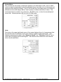
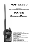
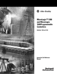
Controller Cable Connection Port (J-2)
The controller I/O (input/output) cable, a component of the distribution block, is connected
to the controller at port J-2. For remote locations of the Controller, extension cables of 12
and 25 feet are available. Refer to spare parts list.
Speed Sensor Connector (J-5)
If the controller has an option for speed compensation it will require a sensor when
operating in “Speed Compensated” mode. The sensor provides the controller with pulses
that are used to calculate the line speed. This sensor is only required when the unit is in
“Speed Compensated” mode. Sensors must be PNP for Siemens. The injector uses a 30
mm inductive proximity sensor to detect the speed of the line. The speed sensor should
be connected to the controller at J-5.
Aux. connector (J-7)
Customers have the option of purchasing a Container Detect Sensor. When used with a
3-sensor system, distribution block output D-3 is used solely for the timing sensor. The
container detect function is now transferred to this input and is strictly for the container
detect. This input is also NPN/PNP specific. The correct sensor must be used.
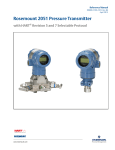
Pressure Tap Outlets
There are two pressure taps on the UltraDoser. One pressure tap allows the controller to
monitor the supply pressure. The other pressure tap allows the controller to monitor the
dosing head pressure.
Blanked off Ports
The controller has a two blanked off ports for future expansion.
Figure 2: Controller Connections
File:UltraDoser with AB1500 controller
Page 12 of 46
Document #15905/040207
Utility Connections
Electric
An electrical power cord, 6 feet long, is supplied with each unit. The power cord is to the
connected to the bottom of the Injector controller at connection point J-1. The injector will
operate with a voltage potential between 100-240VAC, 50/60Hz.
Liquid Nitrogen
The CryotechFlex hose is to be connected to the inlet of the injector. The CryotechFlex
hose male bayonet is provided with a 1/4” FPT on the tip. A 10 micron filter is to be
inserted into this FPT fitting.
The 1/2” JIC end of the CryotechFlex hose is then to be connected to the 1/2” male flare
fitting on the low pressure (22psi) LN2 dewar.
Gaseous Nitrogen
A source of gaseous nitrogen must then be connected to the injector. The pressure must
be a minimum of 60 PSI and the volume is approximately 10 SCFH per 100 containers
per minute.
Installing the Timing Sensor
When input D-3 is used as a combination timing/container sensor the sensor must be
positioned to perform both functions. The optimal distance from the dosing head center to
container detection is approximately 3/4 the distance between containers. For example:
If the centerline distance between two containers is 4.7 in. (120mm), then the timing
sensor is approximately 3.5 in. from the center of the dosing head. The sensor used
must be a PNP type sensor for the Siemens based system. The injector is commonly
supplied with a 12mm ultrasonic sensor.
When D-3 is used solely as a timing sensor it is positioned away from the containers-on a
remote gear typically that provides 1to1 pulses per container. The gear is moved until
the sensor detects the gear. At this point the measurement of container to dosing
head must be made as accurately as possible.
File:UltraDoser with AB1500 controller
Page 13 of 46
Document #15905/040207
ACCESSORIES – SECTION V
Mounting Bracket Assembly
Each injector unit is supplied with a mounting bracket assembly. The assembly consists
of the bracket attaching to the injector with two clamps. These clamps are designed to fit
on 1-1/2” stainless steel rod. The bracket can be mounted in 3 positions: Longest reach
position, the clamps are opposite the arm straight back and both sides perpendicular to
the arm.
Positioning the Dosing Head
The dosing head must be directly over the container opening. The dosing head is installed so
that is approximately 1/2” - 3/4” above the container opening. It may however be installed up
to 3” above the container opening. If there is a possibility of the product splashing out of the
containers, it is suggested to mount the dosing head at the maximum distance.
CryotechFlex Hose
A vacuum insulated hose that provides a connection between the Injector unit and the
LN2 supply.
Inlet Filter
A 10-micron stainless steel inlet filter is provided with each unit. The filter is located inside
the male bayonet on the CryotechFlex hose connection joint.
Encoder Information
An encoder may be used with the injection system in lieu of a speed sensor. An encoder
provides additional pulses per container. The additional pulses allow for greater speed
resolution allowing the injection unit to dose more effectively-specifically at higher line speeds.
The encoder is typically located on a known gear or star wheel matching the speed of the
production line.
The following connection information is for an AMCI encoder p/n DC25F-S1FPRGMCS. The
mating connector is p/n MS-16. Note: Only one channel is used to provide necessary pulses for
the injector system. For correct encoder functionality, shielded cabling must be used. Type CM
Communications Cable is a suitable option. The encoder case should be grounded, either thru
its mounting bracket or separate ground wire.
Encoder Cable Connections:
Encoder
Pin No.
A
D
F
G
Function
Wire color*
CH- A Output
+ DC Output
DC Return
Case Ground
Green or Blue
Red
Black
Shield Wire
File:UltraDoser with AB1500 controller
Page 14 of 46
Controller
Pin No.
4
1
3
N/C
Document #15905/040207
* Wire color refers to the conductors of the shielded communication cable.
Programming the encoder
The DC25F-S1FPRGMCS is a programmable device allowing the user to set the number of
pulses per encoder revolution. For more specific information/instructions log on to the AMCI
website at:
http://www.amci.com/documents.asp.
VALVE HEAD ASSEMBLY – SECTION VI
Electro-pneumatic Actuated Valve
The Injector may be provided with either a standard valve assembly or an Electropneumatic actuated dosing valve assembly. The valve is driven by a pneumatic cylinder.
Gas pressure to the cylinder is controlled by a 24 volt solenoid valve.
File:UltraDoser with AB1500 controller
Page 15 of 46
Document #15905/040207
CONTROLLER – SECTION VII
The electrical control box “controller” is used to provide electrical power for the system, take
input signals from sensors and provide output signals to the injector to activate the dosing valve.
The Cryotech Model 2830 Injection Controller is a Rockwell based system utilizing a ML1500
PLC, Power Supply and HMI (Touch Screen) manufactured by Rockwell Corporation. The
controller PLC has been wired to support PNP type sensors.
The Controller incorporates speed compensation enabling customers to vary line speeds and
still maintain accurate bottle/can dosing while in discrete dose mode.
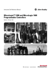
Components
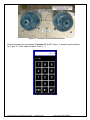
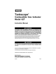
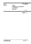
Figure 3: Controller front view
Light Tower
The indicator light provides a visual display of the operating status of the controller.
Green – Unit is in normal operation.
Solid Amber – Unit is in disable mode.
Flashing Amber – Unit is in Quick Service mode.
Flashing Red – Unit is indicating a fault condition but still operational. See Alarms for
additional information.
TP 170B Display Panel
Quick Service Connection
File:UltraDoser with AB1500 controller
Page 16 of 46
224XP PLC
Document #15905/040207
Start-Up Procedure
Step 1: Remove the yellow power cable from its shipping packaging and connect to the
ac input connector located on the bottom of the controller. Connect the I/O cable from
the distribution block of the injector to the I/O connector on the bottom of the controller.
Step 2: Turn unit on
Controller Screens
Upon power-up the controller will go through a self check which will result in the solenoid
activating for 5 pulses. The controller will then complete the boot-up sequence and display the
Liquid Level tubing connection
“Main” screen.
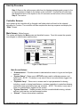
Main Screen - Default screen
The system will display the Main screen as the default screen. From this screen the operator
can navigate to other screens and functions.
Figure 4: Main Screen
Main Screen Buttons:
• “Administrative” - Provides access to administrative screen to log on and configure
terminal.
• “System Setup” - Takes user to SET-UP screen used to calibrate pressure, and
liquid levels. NOTE: This button is only seen if there is an administrator logged into
the system.
• “Dispense Setup” - Takes user to screen used to input parameters for dosing
including; nozzle to dosing head distance, container centerline to centerline distance,
continuous dose speed and pulses per container. NOTE: This button is only seen if
there is an administrator logged into the system.
• “System Functions” - Screen provides controls to enable/disable dosing, activate
self-test, quick service, and auto/manual modes.
• “Alarms” - Screen shows alarm conditions
File:UltraDoser with AB1500 controller
Page 17 of 46
Document #15905/040207
•
“Maintenance” - Used on initial calibration to save the system fill pressure and liquid
level parameters and retrieve them should the need arise to go back to initial
parameters. NOTE: This button is only seen if there is an administrator logged into
the system.
Screen Graphs
• The Main screen is provided with two graphs to provide a status of the system liquid
level and supply pressure. The levels are set in the “System Set-Up” screen. Levels
that are too low or too high generate an alarm and a flashing red light.
Display items
• Line Speed - Shows the speed of the production line. Dose Duration Display– Amount
of time dosing valve is open (milliseconds).
• LCI 2000 / LCI 400 - There are two modes of operation. The LCI 2000 mode is the
speed compensated mode. The LCI 400 mode is not speed compensated.
• Recipe Inactive / Recipe Active - Shows if a Recipe is active or inactive. Does not
appear when in LCI 400 mode.
• Software Versions PLC and HMI
Administrative Screen
Provides access to special functions.
Figure 5: Administrative screen
Administrative Screen Buttons:
• “Log On” - Brings up log on screen. Enter User Name and Password.
• “Log Off” - Logs user off. Only visible after logon.
• “Password” - Allows logged on user to change its password. Only visible after logon.
• “Main” - Takes user to the main screen
• “Configure Terminal” - Allows access to terminal for a variety of functions, such as
touch screen calibration and file management.
File:UltraDoser with AB1500 controller
Page 18 of 46
Document #15905/040207
•
“Set Time” - Communicates with the PLC to set the correct date and time. Date/Time
is set at the CRYOTECH factory and should not require modification. However, if
necessary to change the date or time, see the instructions below.
Set Date/Time – The panel gets its’ clock from the timer located within the
PLC. The PLC must first be told to keep time based upon an input from
the panel. Once complete the clock information is fed back to the panel
and is maintained correctly within the PLC. To set the correct date and
time:
1. Press the “Set Time” button. This brings up the date/time screen in
Figure 6.
Figure 6: Initial date/time screen
2. Press any of the time or date fields. This action will bring up a keypad
allowing for the insertion of time and date information.
3. Once the correct date and time have been inserted press “Write to PLC”
The system will now keep the correct date and time. A delay of up to one
minute may be experienced before the newly inserted date and time appear
in the corresponding fields. This is normal.
File:UltraDoser with AB1500 controller
Page 19 of 46
Document #15905/040207
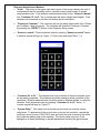
Access and Passwords
The controller has been programmed with a user hierarchy. When accessing certain
screens, buttons, or fields, a user will be required to log on and provide a password.
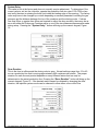
Figure 7 illustrates the log-on screen. Pressing the field area “User” provides the user
with a alpha/numeric keypad, Figure 8, to enter the log-on information. After each has
been entered the “Enter” [ ] button must be pressed to acknowledge the user and/or
password.
Figure 7: Login Screen
Figure 8: Alpha/Numeric Keypad
When first initiating the system it important to change administrative password. The
default user/password is:
Administrative access - All functionality and screens:
User ADMIN, Password ADMIN
It is important to keep a log of passwords to ensure continued access to the system. If it
is lost it cannot be restored without downloading a new program.
IMPORTANT! - CRYOTECH has established an administrative password. This
password will be used by CRYOTECH personnel if an inadvertent erasure of other
passwords occurs.
File:UltraDoser with AB1500 controller
Page 20 of 46
Document #15905/040207
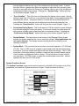
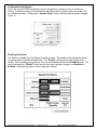
System Setup Screen - Accessible only when logged on.
Set by Cryotech Personnel before the system leaves the factory. There should be no need to
modify these settings.
Figure 9: System Set-Up, Calibration screen
The “System Setup” button on the main screen is the first step prior to incorporating
LN2 into the system. System Setup sets the default values for the liquid level and supply
pressure of the injection system and allows for calibration of each. The PLC has been
programmed to input a “raw” number, a calculated number based upon the initial
readings of the liquid level and supply pressure transducers located within the controller.
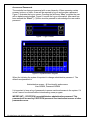
Dispense Setup Screen - Accessible only when logged on.
Provides a means to precisely setup the system for dosing properly.
Figure 10: Dispense Setup Screen
File:UltraDoser with AB1500 controller
Page 21 of 46
Document #15905/040207
Dispense Setup Screen Buttons:
• “Units” - The button in the upper right hand corner of the screen displays the unit of
measurement that the controller uses to calculate correct dose location in speed
compensated mode. If the distance measurements made for the “Sensor to Nozzle”
and “Container CL to CL” are in inches then this button should read English. If the
distances are measured in mm then this button should read Metric.
•
“Pulses per Container” - The controller will not accurately dose bottles if the ‘Pulses
per Container’ value is incorrect. The controller will calculate ‘Pulses per Container’
by pressing the “DETECT” button on the Dispense Setup screen.
•
“Sensor to nozzle” - Enter measured value by pressing “Sensor to nozzle” button.
A numeric keypad will pop up, Figure 11. Enter value and press ‘Enter” [ ]
Figure 11: Numeric Keypad
•
“Container CL to CL” - The distance from one container to the next container must
be accurately measured. This distance should be measured at the centerline of the
containers. Multiple measurements should be made on different bottles to verify this
distance. Enter measured value by pressing “Container CL to CL” button. A
numeric keypad will pop up, Figure 11.
•
“System Delay” - This value is set at the factory and does not normally require
adjustment. To determines if the correct value is set into the controller, operate the
production line at a rate of 100 CPM or less and verify the dose is entering the bottle
just inside the leading edge of the opening. The factory value may have to be
changed up or down depending on several parameters including the gas pressure
File:UltraDoser with AB1500 controller
Page 22 of 46
Document #15905/040207
and the distance between the top of the container and the dosing nozzle. If values
less than 20ms or greater than 40ms are required to adjust the dose correctly, there
may be an error with either the Pulses per Container value or one of the two distance
measurements made during setup. Pressing the “System Delay” button will bring
up the numeric keypad, Figure 11.
•
“Dose Duration” - This is the time in milliseconds the dosing valve is open. Normal
settings range from 15 to 40 ms on a production line that is running approximately 600
containers per minute. The proper duration for each line and product depends on
many different factors and can only be determined on the actual production line.
Pressing the “Dose Duration” button will bring up the numeric keypad, Figure 11.
•
Continuous Dosing Speed - This is the speed in CPM the injection system changes
from discrete dosing to continuous dosing. Continuous dosing is a mode where the
dosing valve is always open unless there are no containers present. Pressing the
“Continuous Dosing Speed” button will bring up the numeric keypad, Figure 11.
•
Recipe Buttons - The two buttons at the bottom of the Dispense Setup Screen
activate the recipes and allow the user to create the recipes. Most applications do
not require Recipes. The Recipe Inactive wording should be visible for most
operating conditions.
•
System Mode - The controller has two modes of automatic operation, LCI 2000 and
LCI 400. The LCI 2000 mode is a speed compensated mode that calculates where
the bottle is for all line speeds and adjusts the dose delay accordingly. The LCI 400
mode has a fixed delay where a container is detected and controller always waits a
“fixed” number of milliseconds before it doses. This mode should only be used for
very slow lines, 100 CPM or less, or when the encoder/speed sensor fails. Normal
operation will be in the LCI 2000 mode.
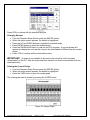
System Functions Screen
The System Functions screen serves as the location for activation of the system once all the
parameters have been set. Buttons are shown in figure 12 and describes as follows:
Figure 12: System Functions Screen
File:UltraDoser with AB1500 controller
Page 23 of 46
Document #15905/040207
System Function Buttons:
• “System” – The enable button allows the system to operate when containers are
detected. The “Disable” button prevents the system from dosing. Upon powering
the system up, the unit automatically defaults into Disabled mode. The user must
press the “Enable” button and the unit must indicate a change from Disabled to
Enabled. Actual dosing starts once line has been started.
• “Self Test” – Used to test the firing of the dosing solenoid. Pressing self test
activates the solenoid for 5 pulses. Self Test can only be activated when the unit is in
Disabled mode.
•
“Quick Service” – The quick service button engages a solenoid which routes
gaseous nitrogen (GN2) through the body to the dosing head. This is typically used
for purging the system to ensure a clean pathway for liquid to flow. If a system has
been left off for some time or exposed to air, moisture may have accumulated which
could result in ice formation causing a blockage in the system. Purging by sending
gaseous nitrogen will “dry out” the system.
•
“Dispense” – The dispense function allows the user to manually open and hold open
the dosing valve when the unit is in the disabled mode. The valve is opened by
pressing and holding the Open Valve button. The button may be held indefinitely
holding open the dosing head valve or pulsed by pressing and releasing the button.
•
“Bottle Sensor Override” - The bottle sensor Override button allows the system to
run even when there is no bottle sensor present. The Override must be activated if
either the bottle sensor is malfunctioning or the timing sensor is being used for both
timing and container present. Pushing button will toggle Override. When operating in
a three sensor mode (speed/encoder, timing, container present), the override button
should indicate Override OFF. If the system is configured in the two sensor mode
(speed/encoder, container), the override button should indicate Override ON.
File:UltraDoser with AB1500 controller
Page 24 of 46
Document #15905/040207
Maintenance and Factory Setup Screen
Used on initial calibration to save the system fill pressure and liquid level parameters and
retrieve them should the need arise to go back to initial parameters.
Figure 13: Maintenance screen
IMPORTANT! – This screen is used on initialization by CRYOTECH Personnel.
Modification of values using this screen could disrupt dosing. Do not use unless
properly trained by CRYOTECH Personnel.
The Restore Defaults button loads the values set by the factory into the minimum and
maximum values for the liquid level and supply pressure. The current values will be
replaced.
Alarm Screen
Indicates alarm conditions that should be examined but may not necessarily require immediate
attention.
Figure14: Alarm Screen
File:UltraDoser with AB1500 controller
Page 25 of 46
Document #15905/040207
Note: Alarm conditions do not stop nitrogen dosing. An alarm is denoted in the light tower
by a flashing red light and is also indicated in the alarm screen, figure 14.
Example:
A flashing red light is noted. When calling up the alarm screen the fault is indicated as a liquid
level low. The system continues to run and dosing well but the light continues to flash red. After
a couple of minutes the light changes back to green indicating all is well and the liquid level low
fault disappears from the alarms screen. The system was just alerting the user of a low level
before the feed system began providing more LN2. The following faults will trigger an alarm
condition:
•
•
•
•
•
•
•
•
Speed sensor fault
Dose valve fault
Dose valve stuck open
Supply Pressure high
Supply Pressure low
Liquid level high
Liquid level empty
Dose Disable depressed
File:UltraDoser with AB1500 controller
Page 26 of 46
Document #15905/040207
Controller Set Up & Operation
The following is set by Cryotech Personnel before the system leaves the factory. There
should be no need to modify these settings. This information is included for reference or
if the system has been taken down for maintenance and has been non-operational for an
extended period of time.
The “System Setup” button on the main screen is the first step prior to incorporating LN2 into
the system. System Setup sets the default values for the liquid level and supply pressure of the
injection system and allows for calibration of each. The PLC has been programmed to input a
“raw” number, a calculated number based upon the initial readings of the liquid level and supply
pressure transducers located within the control box (see figure 2). An example of these raw
numbers is shown.
With no LN2 in either the LCI or in the supply line, the raw values depict the “zero” supply
pressure and liquid level. Press “Save as Min” for both supply pressure and Liquid level. Also
note the “0-25 PSI” and “0-5 PSI” buttons. These buttons correspond to the type of LN2 delivery
system being used. If operating from a Dewar the scale 0-25 PSI is to be used. Pressing this
button will change the bar graph accordingly. The 0-5 PSI will do likewise if the delivery system
is a phase separator. The introduction of LN2 into the system will cause the raw values for
liquid level and supply pressure to rise. When the system has stabilized indicating full levels the
“Save as Max” buttons are pressed setting both the maximum liquid levels and supply pressure
and will be shown in the appropriate graphs. The numbers corresponding to PSI and % of liquid
level will be shown in the fields adjacent to the graphs. The minimum and maximum values can
be set manually by pressing the min or max values and manually entering the new value.
File:UltraDoser with AB1500 controller
Page 27 of 46
Document #15905/040207
System Mode
The controller has two modes of automatic operation, LCI 2000 and LCI 400. The LCI 2000
mode is a speed compensated mode that calculates where the bottle is for all line speeds and
adjusts the dose delay accordingly. The LCI 400 mode has a fixed delay where a container is
detected and controller always waits a “fixed” number of milliseconds before it doses. This
mode should only be used for very slow lines, 100 CPM or less, or when the encoder/speed
sensor fails. Normal operation will be in the LCI 2000 mode.
Units
The button in the upper right hand corner of the screen displays the unit of measurement that
the controller uses to calculate correct dose location in speed compensated mode. If the
distance measurements made for the “Sensor to Nozzle” and “Container CL to CL” are in
inches then this button should read English. If the distances are measured in mm then this
button should read Metric.
File:UltraDoser with AB1500 controller
Page 28 of 46
Document #15905/040207
Pulses per Container
The controller will not accurately dose bottles if the ‘Pulses per Container’ value is incorrect.
The controller will calculate ‘Pulses per Container’ by pressing the “DETECT” button on the
Dispense Setup screen. Always check to see that the “Line Speed” indicator is reading the
actual line speed. This can be done by counting the number of containers that are processed in
one minute and comparing the count to the value displayed on the screen. It is critical that the
Pulses per Container be detected.
Synchronizing the Dose with the Container
Container to Container Distance
The distance from one container to the next container must be accurately measured. This
distance should be measured at the centerline of the containers. Multiple measurements should
be made on different bottles to verify this distance.
File:UltraDoser with AB1500 controller
Page 29 of 46
Document #15905/040207
Figure 15, Container Centerline Measurement
Enter measured value by pressing “Container CL to CL” button. A numeric keypad will pop
up, Figure 16. Enter value and press ‘Enter” [ ]
Figure 16: Numeric Keypad
File:UltraDoser with AB1500 controller
Page 30 of 46
Document #15905/040207
Timing Sensor
The timing sensor synchronizes the dose and the container. It is important that the correct
value be entered into the controller. This parameter is determined by determining the distance
from the center of the dose to the edge of the container opening when the timing sensor initially
detects the bottle or capper clock signal.
Figure 17: Sensor to Nozzle Measurement
Enter measured value by pressing “Sensor to nozzle” button. A numeric keypad will pop up,
Figure 16.
File:UltraDoser with AB1500 controller
Page 31 of 46
Document #15905/040207
System Delay
This value is set at the factory and does not normally require adjustment. To determines if the
correct value is set into the controller, operate the production line at a rate of 100 CPM or less
and verify the dose is entering the bottle just inside the leading edge of the opening. The factory
value may have to be changed up or down depending on several parameters including the gas
pressure and the distance between the top of the container and the dosing nozzle. If values
less than 20ms or greater than 40ms are required to adjust the dose correctly, there may be an
error with either the Pulses per Container value or one of the two distance measurements made
during setup. Pressing the “System Delay” button will bring up the numeric keypad, Figure
16.
Dose Duration
This is the time in milliseconds the dosing valve is open. Normal settings range from 15 to 40
ms on a production line that is running approximately 600 containers per minute. The proper
duration for each line and product depends on many different factors and can only be
determined on the actual production line. Pressing the “Dose Duration” button will bring up the
numeric keypad, Figure 16. If the desired results cannot be obtained by changing the dose
duration, the injection system nozzle can be changed to allow either more or less flow.
File:UltraDoser with AB1500 controller
Page 32 of 46
Document #15905/040207
Continuous Dosing Speed
This is the speed in CPM the injection system changes from discrete dosing to continuous
dosing. Continuous dosing is a mode where the dosing valve is always open unless there are
no containers present. Pressing the “System Delay” button will bring up the numeric keypad,
Figure 16.
Enabling the System
The System is enable from the System Function Screen. The enable button allows the system
to operate when containers are detected. The “Disable” button prevents the system from
dosing. Upon powering the system up, the unit automatically defaults into Disabled mode. The
user must press the “Enable” button and the unit must indicate a change from Disabled to
Enabled. Actual dosing starts once line has been started.
File:UltraDoser with AB1500 controller
Page 33 of 46
Document #15905/040207
Recipes
The two buttons at the bottom of the Dispense Setup Screen activate the recipes and allow the
user to create the recipes. Most applications do not require Recipes. The Recipe Inactive
wording should be visible for most operating conditions.
When the injector is in the LCI 2000 mode there are two methods of operation. Normal
operation is without recipes. A second method of operation is using recipes. The recipe method
allows the storage of unique dose durations for every 100CPM in line speed. This feature can
be used if the line runs products that require different amounts of nitrogen. The controller can
store multiple recipes for different size containers or product lines.
Figure 18 shows the recipe screen with a dose duration of 40ms. Dose durations for all speed
ranges can either be equal or vary with each speed range. Dose durations are set by the user
by pressing to the right of the speed range. Recipes are stored in the Stored Recipe Display
area.
Figure 18: Recipe Screen
File:UltraDoser with AB1500 controller
Page 34 of 46
Document #15905/040207
Creating a recipe
The following steps are required to create a recipe
From the Dispense Setup Screen press the RECIPE button
When the recipe screen appears, the default is highlighted.
Press the OPEN/REFRESH button
A recipe program screen will appear. Press the up and down arrows to highlight the speed
range to be adjusted.
File:UltraDoser with AB1500 controller
Page 35 of 46
Document #15905/040207
Press the ENTER button to make changes to the desired speed range
Enter the desired dose duration in the pop-up screen that appears.
Press enter to save the value
Repeat this procedure for all speed ranges.
Press the SAVE AS button. A pop up window will appear.
Figure 19: Recipe Pop Up Window
Press the EDIT button. A pop up keyboard window will appear.
Enter the name of the recipe using this window.
Press ENTER to save this recipe.
Press the DOWNLOAD button to load into the PLC program. A pop-up window will appear and
advise the user that the recipe to be downloaded is different than the current recipe.
File:UltraDoser with AB1500 controller
Page 36 of 46
Document #15905/040207
Press YES to continue with the download process.
Changing Recipes
• From the Dispense Setup Screen press the RECIPE button
• When the recipe screen appears, the default is highlighted.
• Press the UP and DOWN buttons to highlight the desired recipe
• Press ENTER button to select the desired recipe.
• Press the DOWNLOAD button to load into the PLC program. A pop-up window will
appear and advise the user that the recipe to be downloaded is different than the current
recipe.
• Press YES to continue with the download process.
IMPORTANT! - A recipe is not available to be used by the controller until it has been
“downloaded” to the PLC. After the recipe has been saved it can then be downloaded with the
download button.
Viewing the Current Recipe
• From the Dispense Setup Screen press the RECIPE button
• When the recipe screen appears, the default is highlighted.
• Press the VIEW button to open the recipe graph
The recipe graph can be closed by pressing the CLOSE button.
Figure 20: Recipe Graph
File:UltraDoser with AB1500 controller
Page 37 of 46
Document #15905/040207
DAILY OPERATION PROCEDURES – SECTION VIII
System Start Up
1. If the system is Dewar fed, open the liquid valve on the Dewar.
2. Wait until the injector reservoir is filled with liquid nitrogen, approximately 10 minutes. When
the injector is filling, it will vent heavily and there will be a steady stream of “fog/steam” from
the vent. Once the injector is filled, there will be only a “wisp” of fog coming from the vent. If
the injector overfills and liquid nitrogen starts dripping out the vent, close the liquid valve on
the dewar and call Cryotech service. Do not operate the unit.
3. Ensure the DOSE DISABLE switch on the controller is illuminated (pushed in). This will
prevent the injector from dosing until the operator is ready.
4. Turn the controller “ON” by rotating the Off/On switch mechanism to the On position. The
front panel will show the DISPLAY screen if the controller is functioning correctly.
5. Adjust the dosing parameters. See Set Up Section of this manual for details.
6. Ensure the DOSE DISABLE switch on the controller is not illuminated (pulled out). This will
allow the unit to begin dosing.
System Shut Down
1. Place the DOSE DISABLE switch on the controller in the illuminated (pushed in) position.
This will stop the machine from dosing nitrogen.
2. If the system is Dewar fed, shut the liquid valve on the Dewar. If the hose is disconnected
from the Dewar, the hose termination must be capped to prevent moisture intrusion.
Rotate the Off/On switch to the Off position if the injector will be shut down for over 8
hours or if work will be done on the injector. If the injector is being shut down for a short
time, less than 8 hours, it is not necessary to turn the unit off. It is desirable to have the
heaters “on” during short production breaks to minimize freeze-up of the dosing head or
vent area.
File:UltraDoser with AB1500 controller
Page 38 of 46
Document #15905/040207
MAINTENANCE – SECTION IX
Maintenance - Routine
Nozzle Change Procedure
To change a nozzle:
1.
If using a standard nozzle, the system is comes complete with a nozzle tool (4 mm hex nut
driver) Insert the nozzle removal tool into the nozzle area until the tool connects with the
nozzle. The optional SoftDose nozzles require different removal tools. A hex-head socket
set will work in this application
CAUTION: The dosing head heater is still in operation. Do not expose skin to
prolonged contact with the dosing head heater.
2. Remove the nozzle by rotating the driver in a counter-clock wise direction.
Note: If the nozzle does not loosen easily, drain the Injector and warm up nozzle
with a low power heat gun. Do not expose the nozzle area to direct heat for
extended periods of time as internal seals may be adversely affected.
3. Once the nozzle is removed, place the new nozzle or cleaned nozzle into the hex driver and
insert in the Injector.
Nozzle Cleaning Procedure
1. Remove the nozzle from the Injector.
2. Clean the nozzle opening with a very thin wire and blow dry air through it.
3. Thoroughly dry the nozzle with dry nitrogen gas before re-installing the nozzle.
NOTE: Any moisture left on the nozzle will immediately freeze up when the nozzle is reinstalled.
Dewar Change Out Procedure
The Dewar should be changed out whenever the controller indicates that the supply pressure is
low.
Note: The Injector will continue to dose properly until the liquid level inside the LN2
reservoir runs low. This feature gives the operator a reasonable window in which to
change out the Dewar without disrupting the production operation.
To change out the Dewar:
1. Close the liquid valve on the Dewar.
2. Disconnect the hose from the Dewar using a 5/8” wrench.
3. If a full Dewar is available, immediately connect the CryotechFlex hose to the liquid outlet
on the full Dewar.
4. If a full Dewar is not readily available, plug the 1/2” JIC end of the CryotechFlex hose so
that moisture is not introduced into the Injector.
File:UltraDoser with AB1500 controller
Page 39 of 46
Document #15905/040207
Purging with Gaseous Nitrogen Procedure
General:
Purging is the introduction of “warm” gaseous nitrogen into the system. Any moisture in the
system will form ice when subjected to liquid nitrogen temperatures. Warm nitrogen gas serves
to defrost the system, melt the ice and force out moisture. As part of routine maintenance or if
necessary due to a frozen injector, a purge should be performed. The injector must only be
purged with gaseous nitrogen. Warming the nitrogen gas will accelerate the purging process.
The optimum nitrogen pressure is dependent upon the application, time and equipment
available. In general, a low (approx. 5psi) pressure feed overnight is desirable. If time is of the
essence a 40–50psi feed could be used. For specific recommendations contact Cryotech
Service.
Cryotech recommends that after installation and prior to startup, the injector should be purged to
eliminate any moisture that may be inside the unit. The injector may also require purging when
there is liquid nitrogen flowing out the vent or when the nozzle becomes frozen shut. These two
conditions require the injector be purged using the following procedure.
1. Remove or disable the LN2 source.
2. Drain the injection unit via drain on the bottom of the body
3. Introduce warm GN2 into the fill hose to the top of the injector. Allow GN2 to flow into the
injector until ambient gas is being vented out the vent. This may take several hours if the
injector has just been drained.
4. To purge the dosing head/nozzle area, ensure the gas used to open the solenoid valve is
off. Plug the vent opening so the GN2 is diverted to the dosing head. Remove and
reverse the tubes to the solenoid valve. In other words, switch the bottom to the top and
the top to the bottom. Doing so will actuate the “Bimba” actuator keeping it open once the
gas is turned back on. Turn on the gas to the solenoid valve. Open the GN2 dewar valve
so gas is running through the injector and to the dosing heater area.
5. Continue to run GN2 to the dosing head until ambient gas is being vented out the dosing
head/nozzle area. Again, this may take several hours if the injector has just been drained.
6. Once the procedure is complete replace the tubes to the Bimba, and remove the cap from
the vent.
7. Install the drain plug into the injector body
8. Turn on the LN2 supply
Maintenance - Preventative
Cryotech recommends the following preventive maintenance schedule.
1. Filter Cleaning
Cryotech recommends that the filter be cleaned only as necessary. Note that the filter must be
thoroughly dried with GN2 before it is re-installed.
File:UltraDoser with AB1500 controller
Page 40 of 46
Document #15905/040207
TROUBLE SHOOTING – SECTION X
The Injector has many built-in trouble shooting features. The following describes some trouble
shooting tips.
Condition: The safety relief valve is going off (venting).
Possible Causes
Actions
1. The pressure of the LN2 supply is
greater than 50 psi.
1. Check the pressure of the LN2 supply. If
the supply pressure is greater than 50 psi,
reduce the supply pressure.
Note: A dewar can be vented to
reduce the pressure.
2. The vent is obstructed.
2. Check the Injector vent. If the vent is
obstructed, clear the obstruction. If the
vent is obstructed with ice, contact
Cryotech.
Condition: Liquid is being dispensed out of the vent.
Possible Causes
Actions
1. The LN2 supply pressure is too high.
1. Lower supply pressure to 22 psig or
lower.
2. Ice has developed inside the unit,
causing the internal float valve to
malfunction.
2. Entire Injector unit must be drained of
liquid, allowed to warm up over a minimum
of 24 hours with a continuous purge of
warm nitrogen gas at 5 -25 psig introduced
at the vent opening. The supply connection
must be open to allow the gas to flow
freely through the entire system
Condition: Liquid is being dispensed out of the dosing head even though the
main valve is shut close.
Possible Causes
Actions
1. The LN2 supply pressure is too high
1. Reduce the supply pressure
2. The valve seat is contaminated (ice or
2. Drain LN2 , remove valve, clean valve
particles).
seat.
3. Air supply to the solenoid is reversed.
3. Reverse the LN2 lines that supply and
vent to the solenoid.
File:UltraDoser with AB1500 controller
Page 41 of 46
Document #15905/040207
Condition: No liquid is being dispensed from the dosing head.
Possible Causes
Actions
1. There is insufficient liquid inside the
1. Check the level of LN2. If the level is
Injector unit.
empty or low, open the supply valve.
2. The system is in disable mode.
2a. Pull out dose disable switch
2b. Proceed to System Functions screen
and press enable to enter enable mode.
4. The nozzle is frozen shut
4a. Remove, clean and reinstall the
nozzle.
Note: A purge may be necessary to
remove a frozen nozzle.
5. The container sensor is not detecting a
container.
6. The speed sensor is not functioning
7. All appears ok but the unit still does not
dose.
5. Check sensor connections. Ensure the
sensor is correctly positioned to detect
points (gear tooth or the like) If necessary,
replace sensor.
6. Check the speed sensor is operating
correctly and is sending a signal to the
controller.
8. Is an encoder being used? If not, is the
sensor override button on? Set to on.
Condition: The dosing valve fault error is displayed.
Possible Causes
Actions
1. The dosing valve assembly is not
moving.
1. Check the pneumatic pressure.
There must be at least 60 PSI to
have the dosing valve function
correctly.
Condition: The speed sensor fault error is displayed.
Possible Causes
Actions
1. The speed sensor has been dislodged,
moved or has shifted out of position.
1. Check speed sensor connections.
Readjust.
2. The speed sensor has malfunctioned.
2. Replace speed sensor.
File:UltraDoser with AB1500 controller
Page 42 of 46
Document #15905/040207
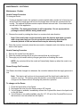
CONTACTING CRYOTECH FOR SERVICE – SECTION XI
If you are experiencing a malfunction with the unit and cannot isolate the problem, Cryotech
technicians are available to provide phone support.
NOTE: BEFORE CALLING CRYOTECH, PLEASE ENSURE THE FOLLOWING
QUESTIONS HAVE BEEN ANSWERED. CRYOTECH PERSONNELCAN BETTER
ASSIST WITH TROUBLE SHOOTING YOUR SYSTEM IF THESE QUESTIONS HAVE
BEEN ANSWERED.
Question
Your Response
1. What is the pressure reading of the LN2 supply?
2. What is the LN2 level reading?
4. What color light (if any) is illuminated on the 5
connectors on the distribution box?
5. Wave an object in front of the container/timing
sensor.
a. Does the sensor cable connector flash yellow?
b. Does the valve sensor flash yellow?
1. Vent heater
2. Dosing head heater
3. Sensor
4. Valve
5. Valve confirm (shunt)
5a. Y/N?
5b. Y/N?
7. What (if any) error messages are displayed on the
main screen of the Injector controller?
8. What color is the indicator light (on top of the
Injector controller)?
a. Red?
b. Green?
c. Yellow?
9. What was the last item changed on the Injector
system?
10. When was the liquid nitrogen supply last
changed?
SERVICE PARTS – SECTION XIV
Name
Description
Cryotech Part Number
Comments
Transducer
0 – 5 PSI
2208
Liquid Level
Transducer
0 – 25 PSI
2209
Supply Pressure
File:UltraDoser with AB1500 controller
Page 43 of 46
Document #15905/040207
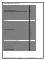
REPLACEMENT PARTS – SECTION XV
Part Description
Part Number
Dosing Head Parts
0.060 Dosing Nozzle
0.050 Dosing Nozzle
0.040 Dosing Nozzle
Nozzle Tool 4mm Hex Nut Driver
Optical sensor (general purpose retro reflective sensor - Banner)
Optical Sensor Assembly(sensor, cable and connector)
Dosing Head Heater Assembly with Cable
Dosing Stem Assembly
Dosing Stem o-ring
Solenoid Valve – 4 way-MOD
102
104
103
362
363
364
106
141
275
140
Injector Reservoir Parts
Inlet Filter
Drain Plug
Safety Relief Valve set to 50 psi
Vent Heater Assembly
Shaft collar
108
109
211
105
315
Injector Controller Parts
Distribution Block with 36” Cable
Controller Extension Cable - 12’
Controller Extension Cable - 25’
Power Input Cable (Wall Plug Included for US orders)
Enable Switch
25A Power Rotary Switch
Switch Shaft
Off/On Rotary Switch Handle Assembly
Power Cord Assembly (wall plug included for US orders)
Controller 24 vdc Power Supply
Solenoid Valve Cable Assembly
Confirm Sensor Cable (from distribution block)
Confirm Sensor with Pico Fast Connector
PNP Container Sensor Cable Assy. For UltraDoser
207
209
210
143
146
2820.10
2820.09
2820.08
410
2820.05
1201
2806
2805
1200
Miscellaneous
10’ CRYOTECH flex hose with Male bayonet
Stainless steel support stand
Gauge, 0-100 psi, 1-1/2”
Gauge, 0-100 psi, 2” , back mount
Gauge, 0-3 psi, 2-1/2”
Complete Gauge Assembly
123
119
135
136
134
133
File:UltraDoser with AB1500 controller
Page 44 of 46
Document #15905/040207
Appendix A – Sensor Positioning
File:UltraDoser with AB1500 controller
Page 45 of 46
Document #15905/040207
Appendix B – Wiring Diagram