1
Installation Guide
BR-Series Adapters
Converged Network Adapter Models BR-1007, 1741, 1020
Fibre Channel Adapter Models BR-804, 815, 825, 1867, 1869
Fabric Adapter Model BR-1860
BR0054504-00 A
Installation Guide BR-Series Adapters
Information furnished in this manual is believed to be accurate and reliable. However, QLogic Corporation assumes no
responsibility for its use, nor for any infringements of patents or other rights of third parties which may result from its
use. QLogic Corporation reserves the right to change product specifications at any time without notice. Applications
described in this document for any of these products are for illustrative purposes only. QLogic Corporation makes no
representation nor warranty that such applications are suitable for the specified use without further testing or
modification. QLogic Corporation assumes no responsibility for any errors that may appear in this document.
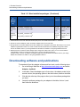
Document Revision History
Revision A, April 30, 2014
Changes
Sections Affected
Initial release.
ii
BR0054504-00 A
Table of Contents
Preface
Intended Audience . . . . . . . . . . . . . . . . . . . . . . . . . . . . . . . . . . . . . . . . . . . .
What Is in this Guide . . . . . . . . . . . . . . . . . . . . . . . . . . . . . . . . . . . . . . . . . .
License Agreements. . . . . . . . . . . . . . . . . . . . . . . . . . . . . . . . . . . . . . . . . . .
Technical Support. . . . . . . . . . . . . . . . . . . . . . . . . . . . . . . . . . . . . . . . . . . . .
Downloading Updates . . . . . . . . . . . . . . . . . . . . . . . . . . . . . . . . . . . . .
Training . . . . . . . . . . . . . . . . . . . . . . . . . . . . . . . . . . . . . . . . . . . . . . . .
Contact Information . . . . . . . . . . . . . . . . . . . . . . . . . . . . . . . . . . . . . . .
Knowledge Database . . . . . . . . . . . . . . . . . . . . . . . . . . . . . . . . . . . . .
1
xv
xv
xix
xx
xx
xxi
xxi
xxi
Product Overview
Fabric Adapters . . . . . . . . . . . . . . . . . . . . . . . . . . . . . . . . . . . . . . . . . . . . . .
AnyIO™ technology. . . . . . . . . . . . . . . . . . . . . . . . . . . . . . . . . . . . . . .
Hardware compatibility . . . . . . . . . . . . . . . . . . . . . . . . . . . . . . . . . . . .
Converged Network Adapters . . . . . . . . . . . . . . . . . . . . . . . . . . . . . . . . . . .
Stand-up adapters . . . . . . . . . . . . . . . . . . . . . . . . . . . . . . . . . . . . . . . .
Mezzanine adapters . . . . . . . . . . . . . . . . . . . . . . . . . . . . . . . . . . . . . .
Hardware compatibility . . . . . . . . . . . . . . . . . . . . . . . . . . . . . . . . . . . .
Host Bus Adapters . . . . . . . . . . . . . . . . . . . . . . . . . . . . . . . . . . . . . . . . . . . .
Stand-up adapters . . . . . . . . . . . . . . . . . . . . . . . . . . . . . . . . . . . . . . . .
Mezzanine adapters . . . . . . . . . . . . . . . . . . . . . . . . . . . . . . . . . . . . . .
Hardware compatibility . . . . . . . . . . . . . . . . . . . . . . . . . . . . . . . . . . . .
Adapter features. . . . . . . . . . . . . . . . . . . . . . . . . . . . . . . . . . . . . . . . . . . . . .
I/O virtualization. . . . . . . . . . . . . . . . . . . . . . . . . . . . . . . . . . . . . . . . . .
Additional general features . . . . . . . . . . . . . . . . . . . . . . . . . . . . . . . . .
FCoE features . . . . . . . . . . . . . . . . . . . . . . . . . . . . . . . . . . . . . . . . . . .
Data Center Bridging and Ethernet features . . . . . . . . . . . . . . . . . . . .
Host bus adapter features . . . . . . . . . . . . . . . . . . . . . . . . . . . . . . . . . .
iii
1
3
5
9
10
11
15
18
19
20
25
27
28
31
34
38
49
BR0054504-00 A
Installation Guide—BR-Series Adapters
Operating system considerations and limitations . . . . . . . . . . . . . . . . . . . . .
Windows . . . . . . . . . . . . . . . . . . . . . . . . . . . . . . . . . . . . . . . . . . . . . . .
Linux . . . . . . . . . . . . . . . . . . . . . . . . . . . . . . . . . . . . . . . . . . . . . . . . . .
Citrix XenServer . . . . . . . . . . . . . . . . . . . . . . . . . . . . . . . . . . . . . . . . .
VMware . . . . . . . . . . . . . . . . . . . . . . . . . . . . . . . . . . . . . . . . . . . . . . . .
Solaris . . . . . . . . . . . . . . . . . . . . . . . . . . . . . . . . . . . . . . . . . . . . . . . . .
Oracle Linux . . . . . . . . . . . . . . . . . . . . . . . . . . . . . . . . . . . . . . . . . . . .
Adapter management features. . . . . . . . . . . . . . . . . . . . . . . . . . . . . . . . . . .
HCM hardware and software requirements. . . . . . . . . . . . . . . . . . . . .
General adapter management. . . . . . . . . . . . . . . . . . . . . . . . . . . . . . .
Fabric Adapter management . . . . . . . . . . . . . . . . . . . . . . . . . . . . . . . .
CNA management . . . . . . . . . . . . . . . . . . . . . . . . . . . . . . . . . . . . . . . .
NIC management . . . . . . . . . . . . . . . . . . . . . . . . . . . . . . . . . . . . . . . .
Host bus adapter management . . . . . . . . . . . . . . . . . . . . . . . . . . . . . .
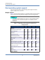
Host operating system support. . . . . . . . . . . . . . . . . . . . . . . . . . . . . . . . . . .
Adapter drivers . . . . . . . . . . . . . . . . . . . . . . . . . . . . . . . . . . . . . . . . . .
Adapters and network technology . . . . . . . . . . . . . . . . . . . . . . . . . . . .
Host Connectivity Manager (HCM) . . . . . . . . . . . . . . . . . . . . . . . . . . .
Adapter software . . . . . . . . . . . . . . . . . . . . . . . . . . . . . . . . . . . . . . . . . . . . .
Driver packages. . . . . . . . . . . . . . . . . . . . . . . . . . . . . . . . . . . . . . . . . .
Management utilities . . . . . . . . . . . . . . . . . . . . . . . . . . . . . . . . . . . . . .
Host Connectivity Manager . . . . . . . . . . . . . . . . . . . . . . . . . . . . . . . . .
Boot code . . . . . . . . . . . . . . . . . . . . . . . . . . . . . . . . . . . . . . . . . . . . . .
CIM Provider . . . . . . . . . . . . . . . . . . . . . . . . . . . . . . . . . . . . . . . . . . . .
Adapter event messages. . . . . . . . . . . . . . . . . . . . . . . . . . . . . . . . . . .
Software installation and driver packages . . . . . . . . . . . . . . . . . . . . . .
Software installation options . . . . . . . . . . . . . . . . . . . . . . . . . . . . . . . .
Boot installation packages . . . . . . . . . . . . . . . . . . . . . . . . . . . . . . . . . . . . . .
Downloading software and publications . . . . . . . . . . . . . . . . . . . . . . . . . . . .
Using BCU commands . . . . . . . . . . . . . . . . . . . . . . . . . . . . . . . . . . . . . . . . .
VMware ESXi 5.0 and later systems . . . . . . . . . . . . . . . . . . . . . . . . . .
Items shipped with your adapter . . . . . . . . . . . . . . . . . . . . . . . . . . . . . . . . .
Stand-up adapters . . . . . . . . . . . . . . . . . . . . . . . . . . . . . . . . . . . . . . . .
Mezzanine adapters . . . . . . . . . . . . . . . . . . . . . . . . . . . . . . . . . . . . . .
2
61
61
62
62
62
62
62
63
64
64
65
65
68
68
70
70
72
74
75
75
77
79
80
81
81
81
87
88
92
93
93
94
94
94
Hardware Installation
Introduction. . . . . . . . . . . . . . . . . . . . . . . . . . . . . . . . . . . . . . . . . . . . . . . . . .
iv
95
BR0054504-00 A
Installation Guide—BR-Series Adapters
ESD precautions . . . . . . . . . . . . . . . . . . . . . . . . . . . . . . . . . . . . . . . . . . . . .
Stand-up adapters . . . . . . . . . . . . . . . . . . . . . . . . . . . . . . . . . . . . . . . . . . . .
What you need for installation . . . . . . . . . . . . . . . . . . . . . . . . . . . . . . .
Installing an adapter . . . . . . . . . . . . . . . . . . . . . . . . . . . . . . . . . . . . . .
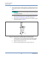
Connecting an adapter to switch or direct-attached storage . . . . . . . .
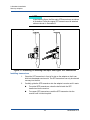
Removing and installing SFP transceivers . . . . . . . . . . . . . . . . . . . . .
Replacing an adapter . . . . . . . . . . . . . . . . . . . . . . . . . . . . . . . . . . . . .
Mezzanine adapters . . . . . . . . . . . . . . . . . . . . . . . . . . . . . . . . . . . . . . . . . . .
BR-804 host bus adapter. . . . . . . . . . . . . . . . . . . . . . . . . . . . . . . . . . .
BR-1867 and BR-1869 host bus adapters. . . . . . . . . . . . . . . . . . . . . .
BR-1007 CNA . . . . . . . . . . . . . . . . . . . . . . . . . . . . . . . . . . . . . . . . . . .
BR-1741 CNA . . . . . . . . . . . . . . . . . . . . . . . . . . . . . . . . . . . . . . . . . . .
3
96
96
96
97
100
100
102
102
102
103
104
105
Software Installation
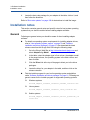
Introduction. . . . . . . . . . . . . . . . . . . . . . . . . . . . . . . . . . . . . . . . . . . . . . . . . .
Installation notes . . . . . . . . . . . . . . . . . . . . . . . . . . . . . . . . . . . . . . . . . . . . .
General . . . . . . . . . . . . . . . . . . . . . . . . . . . . . . . . . . . . . . . . . . . . . . . .
Linux . . . . . . . . . . . . . . . . . . . . . . . . . . . . . . . . . . . . . . . . . . . . . . . . . .
Solaris . . . . . . . . . . . . . . . . . . . . . . . . . . . . . . . . . . . . . . . . . . . . . . . . .
Windows . . . . . . . . . . . . . . . . . . . . . . . . . . . . . . . . . . . . . . . . . . . . . . .
VMware . . . . . . . . . . . . . . . . . . . . . . . . . . . . . . . . . . . . . . . . . . . . . . . .
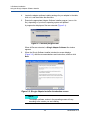
Using the QLogic Adapter Software Installer . . . . . . . . . . . . . . . . . . . . . . . .
Using the GUI-based installer . . . . . . . . . . . . . . . . . . . . . . . . . . . . . . .
Software installation using Software Installer commands . . . . . . . . . .
Software removal using Adapter Software Uninstaller . . . . . . . . . . . .
Software upgrade using the QLogic Adapter Software Installer . . . . .
Software downgrade using the QLogic Adapter Software Installer . . .
Installer log . . . . . . . . . . . . . . . . . . . . . . . . . . . . . . . . . . . . . . . . . . . . .
Using software installation scripts and system tools . . . . . . . . . . . . . . . . . .
Software installation and removal notes . . . . . . . . . . . . . . . . . . . . . . .
Driver installation and removal on Windows systems . . . . . . . . . . . . .
Driver installation and removal on Linux systems . . . . . . . . . . . . . . . .
Installing and removing driver packages on Citrix
XenServer systems . . . . . . . . . . . . . . . . . . . . . . . . . . . . . . . . . . . . . .
Driver installation and removal on Solaris systems . . . . . . . . . . . . . . .
Driver installation and removal on VMware systems. . . . . . . . . . . . . .
v
107
108
108
110
111
111
112
113
114
120
130
135
137
138
138
139
140
146
150
154
157
BR0054504-00 A
Installation Guide—BR-Series Adapters
Confirming driver package installation . . . . . . . . . . . . . . . . . . . . . . . . . . . . .
Confirming driver installation with HCM. . . . . . . . . . . . . . . . . . . . . . . .
Confirming driver installation with Windows tools . . . . . . . . . . . . . . . .
Confirming driver installation with Solaris tools . . . . . . . . . . . . . . . . . .
Confirming driver installation with VMware tools . . . . . . . . . . . . . . . . .
Verifying adapter installation . . . . . . . . . . . . . . . . . . . . . . . . . . . . . . . . . . . .
Installing SNMP subagent . . . . . . . . . . . . . . . . . . . . . . . . . . . . . . . . . . . . . .
Windows systems . . . . . . . . . . . . . . . . . . . . . . . . . . . . . . . . . . . . . . . .
Linux systems . . . . . . . . . . . . . . . . . . . . . . . . . . . . . . . . . . . . . . . . . . .
Updating drivers with HCM. . . . . . . . . . . . . . . . . . . . . . . . . . . . . . . . . . . . . .
Installing HCM to a host from the HCM Agent . . . . . . . . . . . . . . . . . . . . . . .
HCM Agent operations . . . . . . . . . . . . . . . . . . . . . . . . . . . . . . . . . . . . . . . . .
HCM agent restart conditions . . . . . . . . . . . . . . . . . . . . . . . . . . . . . . .
HCM agent commands . . . . . . . . . . . . . . . . . . . . . . . . . . . . . . . . . . . .
HCM configuration data . . . . . . . . . . . . . . . . . . . . . . . . . . . . . . . . . . . . . . . .
Backing up configuration data . . . . . . . . . . . . . . . . . . . . . . . . . . . . . . .
Restoring configuration data . . . . . . . . . . . . . . . . . . . . . . . . . . . . . . . .
Setting IP address and subnet mask on CNAs . . . . . . . . . . . . . . . . . . . . . .
Windows . . . . . . . . . . . . . . . . . . . . . . . . . . . . . . . . . . . . . . . . . . . . . . .
Linux . . . . . . . . . . . . . . . . . . . . . . . . . . . . . . . . . . . . . . . . . . . . . . . . . .
VMware . . . . . . . . . . . . . . . . . . . . . . . . . . . . . . . . . . . . . . . . . . . . . . . .
4
171
171
172
174
176
177
180
180
180
181
182
183
183
183
186
186
186
187
187
187
187
Boot Code
Boot support . . . . . . . . . . . . . . . . . . . . . . . . . . . . . . . . . . . . . . . . . . . . . . . . .
Boot code updates . . . . . . . . . . . . . . . . . . . . . . . . . . . . . . . . . . . . . . . . . . . .
Updating boot code with HCM. . . . . . . . . . . . . . . . . . . . . . . . . . . . . . .
Updating boot code with BCU commands. . . . . . . . . . . . . . . . . . . . . .
Updating older boot code on HBAs . . . . . . . . . . . . . . . . . . . . . . . . . . .
Network boot . . . . . . . . . . . . . . . . . . . . . . . . . . . . . . . . . . . . . . . . . . . . . . . .
BIOS support for network boot . . . . . . . . . . . . . . . . . . . . . . . . . . . . . .
Driver support for network boot . . . . . . . . . . . . . . . . . . . . . . . . . . . . . .
Host system requirements for network boot . . . . . . . . . . . . . . . . . . . .
Configuring network boot. . . . . . . . . . . . . . . . . . . . . . . . . . . . . . . . . . .
gPXE boot . . . . . . . . . . . . . . . . . . . . . . . . . . . . . . . . . . . . . . . . . . . . . .
vi
188
189
191
192
192
193
194
195
196
196
202
BR0054504-00 A
Installation Guide—BR-Series Adapters
Boot over SAN . . . . . . . . . . . . . . . . . . . . . . . . . . . . . . . . . . . . . . . . . . . . . . .
QLogic Legacy BIOS support . . . . . . . . . . . . . . . . . . . . . . . . . . . . . . .
QLogic UEFI support . . . . . . . . . . . . . . . . . . . . . . . . . . . . . . . . . . . . . .
Booting from direct attach storage. . . . . . . . . . . . . . . . . . . . . . . . . . . .
Host system requirements for boot over SAN . . . . . . . . . . . . . . . . . . .
Storage system requirements for boot over SAN . . . . . . . . . . . . . . . .
Disabling N_Port trunking . . . . . . . . . . . . . . . . . . . . . . . . . . . . . . . . . .
Important notes for configuring boot over SAN . . . . . . . . . . . . . . . . . .
Configuring boot over SAN . . . . . . . . . . . . . . . . . . . . . . . . . . . . . . . . .
Operating system and driver installation on boot LUNs . . . . . . . . . . .
Installing the full driver package on boot LUNs . . . . . . . . . . . . . . . . . .
Fabric-based boot LUN discovery . . . . . . . . . . . . . . . . . . . . . . . . . . . . . . . .
Configuring fabric-based boot LUN discovery (Brocade fabrics). . . . .
Configuring fabric-based boot LUN discovery (Cisco fabrics) . . . . . . .
Boot systems over SAN without operating system or local drive . . . . . . . . .
Using a LiveCD image. . . . . . . . . . . . . . . . . . . . . . . . . . . . . . . . . . . . .
Creating a WinPE image . . . . . . . . . . . . . . . . . . . . . . . . . . . . . . . . . . .
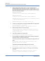
Updating Windows driver on adapter used for boot over SAN. . . . . . . . . . .
Using VMware Auto Deployment to boot QLogic custom images . . . . . . . .
Building a custom image for auto deployment or ISO image . . . . . . .
Configuring BIOS with the BIOS Configuration Utility . . . . . . . . . . . . . . . . .
Configuring BIOS with HCM or BCU commands . . . . . . . . . . . . . . . . . . . . .
Configuring UEFI . . . . . . . . . . . . . . . . . . . . . . . . . . . . . . . . . . . . . . . . . . . . .
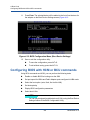
Using Network menu options. . . . . . . . . . . . . . . . . . . . . . . . . . . . . . . .
Using Storage menu options . . . . . . . . . . . . . . . . . . . . . . . . . . . . . . . .
Fabric Adapter configuration support . . . . . . . . . . . . . . . . . . . . . . . . .
IBM Agentless Inventory Manager (AIM) support . . . . . . . . . . . . . . . .
Alternate methods for configuring UEFI . . . . . . . . . . . . . . . . . . . . . . . . . . . .
UEFI Driver Health Check . . . . . . . . . . . . . . . . . . . . . . . . . . . . . . . . . . . . . .
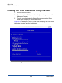
Accessing UEFI driver health screen through IBM server. . . . . . . . . .
vii
203
204
206
207
208
209
210
210
211
217
233
234
235
237
240
241
242
243
243
244
246
254
255
255
257
259
259
260
263
264
BR0054504-00 A
Installation Guide—BR-Series Adapters
5
Specifications
Fabric Adapters . . . . . . . . . . . . . . . . . . . . . . . . . . . . . . . . . . . . . . . . . . . . . .
PCI Express interface . . . . . . . . . . . . . . . . . . . . . . . . . . . . . . . . . . . . .
Hardware specifications . . . . . . . . . . . . . . . . . . . . . . . . . . . . . . . . . . .
Cabling (stand-up adapters) . . . . . . . . . . . . . . . . . . . . . . . . . . . . . . . .
Adapter LED operation (stand-up adapters) . . . . . . . . . . . . . . . . . . . .
Environmental and power requirements . . . . . . . . . . . . . . . . . . . . . . .
Converged Network Adapters . . . . . . . . . . . . . . . . . . . . . . . . . . . . . . . . . . .
PCI Express interface . . . . . . . . . . . . . . . . . . . . . . . . . . . . . . . . . . . . .
Hardware specifications . . . . . . . . . . . . . . . . . . . . . . . . . . . . . . . . . . .
Cabling (stand-up adapters) . . . . . . . . . . . . . . . . . . . . . . . . . . . . . . . .
Adapter LED operation (stand-up adapters) . . . . . . . . . . . . . . . . . . . .
Environmental and power requirements . . . . . . . . . . . . . . . . . . . . . . .
Host Bus Adapters . . . . . . . . . . . . . . . . . . . . . . . . . . . . . . . . . . . . . . . . . . . .
PCI Express interface . . . . . . . . . . . . . . . . . . . . . . . . . . . . . . . . . . . . .
Hardware specifications . . . . . . . . . . . . . . . . . . . . . . . . . . . . . . . . . . .
Cabling (stand-up adapters) . . . . . . . . . . . . . . . . . . . . . . . . . . . . . . . .
Adapter LED operation (stand-up adapters) . . . . . . . . . . . . . . . . . . . .
Environmental and power requirements . . . . . . . . . . . . . . . . . . . . . . .
Fibre Channel standards compliance. . . . . . . . . . . . . . . . . . . . . . . . . . . . . .
Regulatory compliance. . . . . . . . . . . . . . . . . . . . . . . . . . . . . . . . . . . . . . . . .
Stand-up adapters . . . . . . . . . . . . . . . . . . . . . . . . . . . . . . . . . . . . . . . .
Mezzanine adapters . . . . . . . . . . . . . . . . . . . . . . . . . . . . . . . . . . . . . .
6
Adapter Support
Providing details for support. . . . . . . . . . . . . . . . . . . . . . . . . . . . . . . . . . . . .
Using Support Save . . . . . . . . . . . . . . . . . . . . . . . . . . . . . . . . . . . . . . . . . . .
Initiating Support Save through HCM . . . . . . . . . . . . . . . . . . . . . . . . .
Initiating Support Save through BCU commands . . . . . . . . . . . . . . . .
Initiating Support Save through the Internet browser . . . . . . . . . . . . .
Initiating Support Save through a heartbeat failure . . . . . . . . . . . . . . .
Support Save differences . . . . . . . . . . . . . . . . . . . . . . . . . . . . . . . . . .
A
265
265
266
272
274
276
277
277
278
282
283
285
288
288
289
292
293
295
297
297
298
306
310
313
315
316
317
317
317
Adapter Configuration
Introduction. . . . . . . . . . . . . . . . . . . . . . . . . . . . . . . . . . . . . . . . . . . . . . . . . .
Storage instance-specific persistent parameters . . . . . . . . . . . . . . . . . . . . .
Managing instance-specific persistent parameters . . . . . . . . . . . . . . .
viii
319
319
323
BR0054504-00 A
Installation Guide—BR-Series Adapters
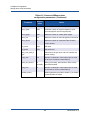
Storage driver-level parameters . . . . . . . . . . . . . . . . . . . . . . . . . . . . . . . . . .
Linux and VMware driver configuration parameters . . . . . . . . . . . . . .
Windows driver configuration parameters . . . . . . . . . . . . . . . . . . . . . .
Solaris driver configuration parameters. . . . . . . . . . . . . . . . . . . . . . . .
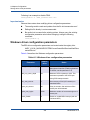
Network driver parameters . . . . . . . . . . . . . . . . . . . . . . . . . . . . . . . . . . . . . .
Windows . . . . . . . . . . . . . . . . . . . . . . . . . . . . . . . . . . . . . . . . . . . . . . .
Linux . . . . . . . . . . . . . . . . . . . . . . . . . . . . . . . . . . . . . . . . . . . . . . . . . .
VMware . . . . . . . . . . . . . . . . . . . . . . . . . . . . . . . . . . . . . . . . . . . . . . . .
Enabling jumbo frames for Solaris. . . . . . . . . . . . . . . . . . . . . . . . . . . .
B
324
324
328
331
332
333
338
344
352
MIB Reference
Index
ix
BR0054504-00 A
Installation Guide—BR-Series Adapters
x
BR0054504-00 A
Installation Guide—BR-Series Adapters
List of Figures
Figure
Page
i
Installing adapters using this document . . . . . . . . . . . . . . . . . . . . . . . . . . . . . . . . . .
xvii
1-1
BR-1860 Fabric Adapter (heat sink removed) . . . . . . . . . . . . . . . . . . . . . . . . . . . . .
2
1-2
BR-1020 stand-up CNA with low-profile mounting bracket (heat sink removed) . . .
10
1-3
BR-1007 CNA . . . . . . . . . . . . . . . . . . . . . . . . . . . . . . . . . . . . . . . . . . . . . . . . . . . . .
12
1-4
BR-1741 mezzanine card. . . . . . . . . . . . . . . . . . . . . . . . . . . . . . . . . . . . . . . . . . . . .
14
1-5
BR-825 Host bus adapter with low-profile mounting bracket
(heat sink removed) . . . . . . . . . . . . . . . . . . . . . . . . . . . . . . . . . . . . . . . . . . . . . . . . .19
1-6
BR-804 mezzanine host bus adapter. . . . . . . . . . . . . . . . . . . . . . . . . . . . . . . . . . . .
21
1-7
BR-1867 host bus adapter (bottom view). . . . . . . . . . . . . . . . . . . . . . . . . . . . . . . . .
22
1-8
BR-1869 Host bus adapter (bottom view) . . . . . . . . . . . . . . . . . . . . . . . . . . . . . . . .
24
2-1
Removing or installing adapter mounting bracket . . . . . . . . . . . . . . . . . . . . . . . . . .
98
2-2
Installing adapter in system chassis. . . . . . . . . . . . . . . . . . . . . . . . . . . . . . . . . . . . .
99
2-3
Removing or installing fiber-optic and copper SFP transceivers . . . . . . . . . . . . . . .
101
3-1
Installer progress bar . . . . . . . . . . . . . . . . . . . . . . . . . . . . . . . . . . . . . . . . . . . . . . . .
115
3-2
QLogic Adapter Installer Introduction screen . . . . . . . . . . . . . . . . . . . . . . . . . . . . . .
115
3-3
Existing software components installed screen . . . . . . . . . . . . . . . . . . . . . . . . . . . .
116
3-4
Choose Install Set screen . . . . . . . . . . . . . . . . . . . . . . . . . . . . . . . . . . . . . . . . . . . .
117
3-5
Preinstallation Summary screen . . . . . . . . . . . . . . . . . . . . . . . . . . . . . . . . . . . . . . .
118
3-6
Install Complete screen . . . . . . . . . . . . . . . . . . . . . . . . . . . . . . . . . . . . . . . . . . . . . .
119
3-7
Uninstall Options screen . . . . . . . . . . . . . . . . . . . . . . . . . . . . . . . . . . . . . . . . . . . . .
132
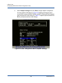
4-1
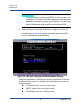
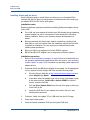
PXE BIOS Configuration Menu (Select the Adapter) . . . . . . . . . . . . . . . . . . . . . . . .
197
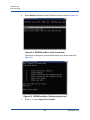
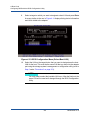
4-2
PXE BIOS Configuration Menu (Adapter Settings) . . . . . . . . . . . . . . . . . . . . . . . . .
198
4-3
Configuring boot over SAN . . . . . . . . . . . . . . . . . . . . . . . . . . . . . . . . . . . . . . . . . . .
212
4-4
GRUB Boot Menu (Solaris selected) . . . . . . . . . . . . . . . . . . . . . . . . . . . . . . . . . . . .
228
4-5
GRUB Boot Menu (Configuring devices) . . . . . . . . . . . . . . . . . . . . . . . . . . . . . . . . .
228
4-6
BIOS Configuration Menu (Select the Adapter) . . . . . . . . . . . . . . . . . . . . . . . . . . . .
247
4-7
BIOS Configuration Menu (Adapter Configuration) . . . . . . . . . . . . . . . . . . . . . . . . .
248
4-8
BIOS Configuration Menu (Adapter Settings) . . . . . . . . . . . . . . . . . . . . . . . . . . . . .
249
4-9
BIOS Configuration Menu (Boot Device Settlings). . . . . . . . . . . . . . . . . . . . . . . . . .
251
4-10 BIOS Configuration Menu (Select Port Target) . . . . . . . . . . . . . . . . . . . . . . . . . . . .
252
4-11 BIOS Configuration Menu (Select Boot LUN) . . . . . . . . . . . . . . . . . . . . . . . . . . . . .
253
4-12 BIOS Configuration Menu (Boot Device Settings) . . . . . . . . . . . . . . . . . . . . . . . . . .
254
4-13 UEFI Driver Health Menu . . . . . . . . . . . . . . . . . . . . . . . . . . . . . . . . . . . . . . . . . . . . .
264
5-1
LED locations for dual-port (A) and single-port (B) BR-1860 Fabric Adapters. . . . .
274
5-2
LED locations for BR-1020 CNA . . . . . . . . . . . . . . . . . . . . . . . . . . . . . . . . . . . . . . .
283
5-3
LED locations for BR-825 HBA (A) and BR-815 (B) . . . . . . . . . . . . . . . . . . . . . . . .
293
A-1
Properties dialog box for adapter port (Advanced tab) . . . . . . . . . . . . . . . . . . . . . .
336
A-2
Advanced Properties dialog box for team . . . . . . . . . . . . . . . . . . . . . . . . . . . . . . . .
337
xi
BR0054504-00 A
Installation Guide—BR-Series Adapters
xii
BR0054504-00 A
Installation Guide—BR-Series Adapters
Table
1-1
1-2
1-3
1-4
1-5
1-6
1-7
1-8
1-9
1-10
1-11
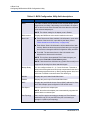
4-1
4-2
5-1
5-2
5-3
5-4
5-5
5-6
5-7
5-8
5-9
5-10
5-11
5-12
5-13
5-14
5-15
5-16
5-17
5-18
5-19
5-20
5-21
5-22
5-23
A-1
A-2
A-3
A-4
List of Tables
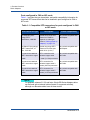
Compatible SFP transceivers for ports configured in CNA or NIC mode . . . . . . . . .
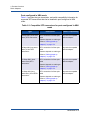
Compatible SFP transceivers for ports configured in HBA mode . . . . . . . . . . . . . .
QLogic Fibre Channel CNAs . . . . . . . . . . . . . . . . . . . . . . . . . . . . . . . . . . . . . . . . . .
Compatible SFP transceivers for QLogic stand-up CNAs . . . . . . . . . . . . . . . . . . . .
Host bus adapter model information . . . . . . . . . . . . . . . . . . . . . . . . . . . . . . . . . . . .
Factory default physical function (PF) configurations for Fabric Adapter ports.. . . .
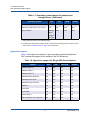
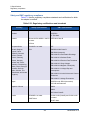
Operating system support for network and storage drivers . . . . . . . . . . . . . . . . . . .
Hypervisor support for QLogic BR-Series Adapters. . . . . . . . . . . . . . . . . . . . . . . . .
Installer script commands . . . . . . . . . . . . . . . . . . . . . . . . . . . . . . . . . . . . . . . . . . . .
Supported software installation packages . . . . . . . . . . . . . . . . . . . . . . . . . . . . . . . .
Boot installation packages . . . . . . . . . . . . . . . . . . . . . . . . . . . . . . . . . . . . . . . . . . . .
BIOS Configuration Utility field descriptions. . . . . . . . . . . . . . . . . . . . . . . . . . . . . . .
Fabric Adapter configuration support . . . . . . . . . . . . . . . . . . . . . . . . . . . . . . . . . . . .
Fabric Adapter mounting brackets . . . . . . . . . . . . . . . . . . . . . . . . . . . . . . . . . . . . . .
Fabric Adapter hardware specifications . . . . . . . . . . . . . . . . . . . . . . . . . . . . . . . . . .
GbE transceiver cable specifications . . . . . . . . . . . . . . . . . . . . . . . . . . . . . . . . . . . .
Fibre Channel transceiver cable specifications . . . . . . . . . . . . . . . . . . . . . . . . . . . .
LED operation . . . . . . . . . . . . . . . . . . . . . . . . . . . . . . . . . . . . . . . . . . . . . . . . . . . . .
Environmental and power requirements . . . . . . . . . . . . . . . . . . . . . . . . . . . . . . . . .
CNA mounting brackets . . . . . . . . . . . . . . . . . . . . . . . . . . . . . . . . . . . . . . . . . . . . . .
CNA hardware specifications . . . . . . . . . . . . . . . . . . . . . . . . . . . . . . . . . . . . . . . . . .
Transceiver and cable specifications . . . . . . . . . . . . . . . . . . . . . . . . . . . . . . . . . . . .
LED operation . . . . . . . . . . . . . . . . . . . . . . . . . . . . . . . . . . . . . . . . . . . . . . . . . . . . .
Environmental and power requirements . . . . . . . . . . . . . . . . . . . . . . . . . . . . . . . . .
Environmental and power requirements for BR-1007 CNA mezzanine card . . . . . .
Environmental and power requirements for BR-1741 CNA mezzanine card . . . . . .
Mounting brackets for stand-up HBAs . . . . . . . . . . . . . . . . . . . . . . . . . . . . . . . . . . .
Supported Fibre Channel features . . . . . . . . . . . . . . . . . . . . . . . . . . . . . . . . . . . . . .
Fibre Channel transceiver and cable specifications. . . . . . . . . . . . . . . . . . . . . . . . .
LED operation . . . . . . . . . . . . . . . . . . . . . . . . . . . . . . . . . . . . . . . . . . . . . . . . . . . . .
Environmental and power requirements . . . . . . . . . . . . . . . . . . . . . . . . . . . . . . . . .
Environmental and power requirements for BR-1867 mezzanine card . . . . . . . . . .
Environmental and power requirements for BR-1869 mezzanine card . . . . . . . . . .
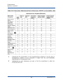
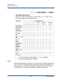
Regulatory certifications and standards . . . . . . . . . . . . . . . . . . . . . . . . . . . . . . . . . .
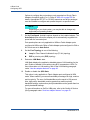
Hazardous Substances/Toxic Substances (HS/TS) concentration chart . . . . . . . . .
Regulatory certifications and standards . . . . . . . . . . . . . . . . . . . . . . . . . . . . . . . . . .
Adapter instance-specific parameters . . . . . . . . . . . . . . . . . . . . . . . . . . . . . . . . . . .
Linux and VMware driver configuration parameters. . . . . . . . . . . . . . . . . . . . . . . . .
Windows driver configuration parameters . . . . . . . . . . . . . . . . . . . . . . . . . . . . . . . .
Solaris driver configuration parameters . . . . . . . . . . . . . . . . . . . . . . . . . . . . . . . . . .
xiii
Page
6
7
9
15
18
28
70
71
78
83
91
250
259
265
266
272
273
274
276
277
278
282
284
285
286
287
288
289
292
294
295
296
297
301
304
308
320
324
328
331
BR0054504-00 A
Installation Guide—BR-Series Adapters
A-5
A-6
A-7
A-8
A-9
B-1
Network driver configuration parameters . . . . . . . . . . . . . . . . . . . . . . . . . . . . . . . . .
Network driver configuration parameters . . . . . . . . . . . . . . . . . . . . . . . . . . . . . . . . .
Network driver module parameters . . . . . . . . . . . . . . . . . . . . . . . . . . . . . . . . . . . . .
NetQueues and filters per NetQueue for CNAs . . . . . . . . . . . . . . . . . . . . . . . . . . . .
NetQueues and filters per NetQueue for Fabric Adapter ports in CNA mode . . . . .
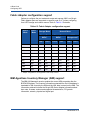
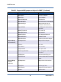
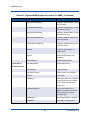
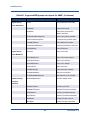
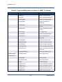
Supported MIB groups and objects for SNMP . . . . . . . . . . . . . . . . . . . . . . . . . . . . .
xiv
333
338
344
350
351
353
BR0054504-00 A
Preface
Intended Audience
This guide introduces users to the BR-Series adapters and explains its installation
and service. It is intended for users who are responsible for installing and
servicing network equipment.
What Is in this Guide
This manual provides installation and reference information on QLogic host bus
adapters, converged network adapters (CNAs), and Fabric Adapters for version
3.2.4. It is organized to help you find the information that you want as quickly and
easily as possible.
The document contains the following components:
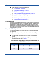
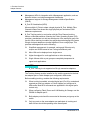
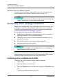
Chapter 1, "Product Overview" provides a detailed product overview and
description. Information on adapter hardware and software compatibility is
also included.
Chapter 2, "Hardware Installation" provides procedures to install adapter
hardware and connect to the fabric or switch. Also included are procedures
to verify hardware and software installation.
Chapter 3, "Software Installation" provides procedures to install software,
such as the QLogic Host Connectivity Manager (HCM) and driver packages.
Also included are instructions to verify software and hardware installation.
Use this chapter to install software on the host system where you have
installed the adapter.
Chapter 4, "Boot Code" describes host boot support available on the
adapter and provides an introduction to boot over SAN. It also includes
procedures to update adapter boot code, configure boot over SAN, and
configure fabric-based boot over SAN. Use this chapter when configuring a
host to boot its operating system from a boot device located somewhere on
the SAN instead of the host’s local disk or direct-attached storage.
Chapter 5, "Specifications" includes details on adapter physical
characteristics, LED operation, environmental requirements, and power
requirements. Also included are Fibre Channel standards, regulatory, and
safety compliance information.
xv
BR0054504-00 A
Installation Guide—BR-Series Adapters
Preface
What Is in this Guide
Chapter 6, "Adapter Support" provides details on information to provide your
QLogic adapter support provider for hardware, firmware, and software
support, including product repairs and part ordering. This chapter also
provides an overview of using the Support Save feature to collect debug
information from the driver, internal libraries, and firmware so that you can
pass this to your provider for more efficient problem resolution.
Appendix A, "Adapter Configuration" is optional for expert network
administrators, who need to modify values for adapter instance-specific
persistent and driver-level configuration parameters.
Appendix B, "MIB Reference" provides information on the MIB groups and
objects that support the Simple Network Management Protocol (SNMP) for
CNAs and Fabric Adapter ports configured in CNA mode.
xvi
BR0054504-00 A
Installation Guide—BR-Series Adapters
Preface
What Is in this Guide
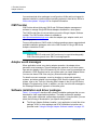
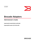
Figure i illustrates a flowchart of how to use chapters in this manual to install and
configure adapters.
Start
Chapter 1
Determine host system compatibility,
required hardware, and required
software packages for installation.
Chapter 2
Install adapter hardware in host system,
connect to switch, and verify installation.
Chapter 3
· Install adapter drivers, utilities, and other
software in host system.
· Verify software and hardware installation.
· Configure HCM agent operation as necessary.
· Configure network addressing (CNA only).
Yes
Booting from
external
boot device?
No
Chapter 4
· Configure boot over SAN on BIOS- or UEFIbased systems.
· Install operating system, adapter drivers,
utilities, and other software on boot devices.
· Configure fabric-based boot LUN discovery
if needed.
· Boot host systems without operating systems
or remote drives if needed.
Appendix A
Optional instructions for expert users.
Configure instance-specific and driver-level
parameters to control adapter operation.
Figure i. Installing adapters using this document
Related Materials
For information about downloading documentation from the QLogic Web site, see
“Downloading Updates” on page xx.
xvii
BR0054504-00 A
Installation Guide—BR-Series Adapters
Preface
What Is in this Guide
Documentation Conventions
This guide uses the following documentation conventions:
NOTE
CAUTION
without an alert symbol indicates the presence of a hazard
that could cause damage to equipment or loss of data.
Text in blue font indicates a hyperlink (jump) to a figure, table, or section in
this guide, and links to Web sites are shown in underlined blue. For
example:
provides additional information.
Table 9-2 lists problems related to the user interface and remote agent.
See “Installation Checklist” on page 6.
For more information, visit www.qlogic.com.
Text in bold font indicates user interface elements such as command
names, keywords, operands and text to enter in the GUI or CLI. For
example:
Click the Start button, point to Programs, point to Accessories, and
then click Command Prompt.
Under Notification Options, select the Warning Alarms check box.
Text in Courier font indicates a file name, directory path, or command line
text. For example:
To return to the root directory from anywhere in the file structure:
Type cd /root and press ENTER.
Enter the following command: sh ./install.bin
Key names and key strokes are indicated with UPPERCASE:
Press CTRL+P.
Press the UP ARROW key.
Text in italics indicates terms, emphasis, variables, or document titles. For
example:
For a complete listing of license agreements, refer to the QLogic
Software End User License Agreement.
What are shortcut keys?
To enter the date type mm/dd/yyyy (where mm is the month, dd is the
day, and yyyy is the year).
xviii
BR0054504-00 A
Installation Guide—BR-Series Adapters
Preface
License Agreements
Topic titles between quotation marks identify related topics either within this
manual or in the online help, which is also referred to as the help system
throughout this document.
Command line interface (CLI) command syntax conventions include the
following:
< > (angle brackets) indicate a variable whose value you must specify.
For example:
<serial_number>
NOTE
For CLI commands only, variable names are always indicated
using angle brackets instead of italics.
[ ] (square brackets) indicate an optional parameter. For example:
[<file_name>] means specify a file name, or omit it to select
the default file name.
| (vertical bar) indicates mutually exclusive options; select one option
only. For example:
on|off
1|2|3|4
... (ellipsis) indicates that the preceding item may be repeated. For
example:
x... means one or more instances of x.
[x...] means zero or more instances of x.
( ) (parentheses) and { } (braces) are used to avoid logical ambiguity.
For example:
a|b c is ambiguous
{(a|b) c} means a or b, followed by c
{a|(b c)} means either a, or b c
License Agreements
Refer to the QLogic Software End User License Agreement for a complete listing
of all license agreements affecting this product.
xix
BR0054504-00 A
Installation Guide—BR-Series Adapters
Preface
Technical Support
Technical Support
Customers should contact their authorized maintenance provider for technical
support of their QLogic products. QLogic-direct customers may contact QLogic
Technical Support; others will be redirected to their authorized maintenance
provider. Visit the QLogic support Web site listed in Contact Information for the
latest firmware and software updates.
For details about available service plans, or for information about renewing and
extending your service, visit the Service Program Web page at
http://www.qlogic.com/Support/Pages/ServicePrograms.aspx.
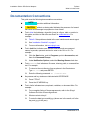
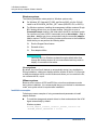
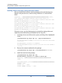
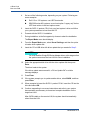
Downloading Updates
The QLogic Web site provides periodic updates to product firmware, software,
and documentation.
To download firmware, software, and documentation:
1.
Go to the QLogic Downloads and Documentation page:
http://driverdownloads.qlogic.com.
2.
Type the QLogic model name in the search box.
3.
In the search results list, locate and select the firmware, software, or
documentation for your product.
4.
View the product details Web page to ensure that you have the correct
firmware, software, or documentation. For additional information, click
Read Me and Release Notes under Support Files.
5.
Click Download Now.
6.
Save the file to your computer.
7.
If you have downloaded firmware, software, drivers, or boot code, follow the
installation instructions in the Readme file.
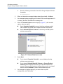
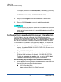
Instead of typing a model name in the search box, you can perform a guided
search as follows:
1.
Click the product type tab: Adapters, Switches, Routers, or ASICs.
2.
Click the corresponding button to search by model or operating system.
3.
Click an item in each selection column to define the search, and then click
Go.
4.
Locate the firmware, software, or document you need, and then click the
item’s name to download or open the item.
xx
BR0054504-00 A
Installation Guide—BR-Series Adapters
Preface
Technical Support
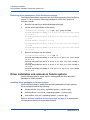
Training
QLogic Global Training maintains a Web site at www.qlogictraining.com offering
online and instructor-led training for all QLogic products. In addition, sales and
technical professionals may obtain Associate and Specialist-level certifications to
qualify for additional benefits from QLogic.
Contact Information
QLogic Technical Support for products under warranty is available during local
standard working hours excluding QLogic Observed Holidays. For customers with
extended service, consult your plan for available hours. For Support phone
numbers, see the Contact Support link at support.qlogic.com.
Support Headquarters
QLogic Corporation
4601 Dean Lakes Blvd.
Shakopee, MN 55379 USA
QLogic Web Site
www.qlogic.com
Technical Support Web Site
http://support.qlogic.com
Technical Support E-mail
[email protected]
Technical Training E-mail
[email protected]
Knowledge Database
The QLogic knowledge database is an extensive collection of QLogic product
information that you can search for specific solutions. QLogic is constantly adding
to the collection of information in the database to provide answers to your most
urgent questions. Access the database from the QLogic Support Center:
http://support.qlogic.com.
xxi
BR0054504-00 A
Installation Guide—BR-Series Adapters
Preface
Technical Support
xxii
BR0054504-00 A
1
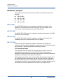
Product Overview
Fabric Adapters
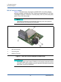
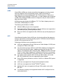
The BR-1860 stand-up Fabric Adapter is a low-profile MD2 form-factor PCI
Express (PCIe) card measuring 16.751 cm by 6.878 cm (6.595 in. by 2.708 in.)
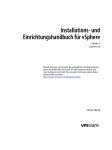
that installs in standard host computer systems. Figure 1-1 illustrates major
components of the dual-port BR-1860 Fabric Adapter. BR-1860 single- or
dual-port adapter models can ship with the following configurations of small
form-factor pluggable (SFP) transceivers:
Single-port model - 16 Gbps Fibre Channel SFP+ transceiver, 10GbE SFP+
transceiver, or without optics.
Dual-port model - Two 16 Gbps Fibre Channel SFP+ transceiver, two 10GbE
SFP+ transceivers, or without optics.
Although adapters may ship with specific optics (or no optics) installed, you can
replace with compatible optics, such as 8 Gbps FC SFP transceivers, long-wave
SFP transceivers, and SFP+ direct-attach copper cables. Refer to “Hardware
compatibility” on page 5 for more information.
Note that the following illustration is representative and may have minor physical
differences from the card that you purchased.
1
BR0054504-00 A
1–Product Overview
Fabric Adapters
1
2
3
6
4
5
1
LEDs for port 1 SFP transceiver.
2
Cable connectors for port 1 and port 0 SFP transceiver (Fiber-optic SFP illustrated).
3
LEDs for port 0 SFP transceiver.
4
Low-profile mounting bracket.
Note: The adapter ships with the standard (full-height) mounting bracket installed.
5
PCIe x8 connector.
6
ASIC
Figure 1-1. BR-1860 Fabric Adapter (heat sink removed)
NOTE
Use only Brocade®-branded SFP+ laser transceivers supplied with stand-up
Fabric Adapters.
2
BR0054504-00 A
1–Product Overview
Fabric Adapters
AnyIO™ technology
Although the BR-1860 can be shipped in a variety of SFP transceiver
configurations, you can change the port function to the following modes using the
QLogic AnyIO™ technology, provided the correct SFP transceiver is installed for
the port:
HBA or Fibre Channel mode. This mode utilizes the QLogic Fibre Channel
storage driver. An 8 or 16 Gbps Fibre Channel SFP transceiver can be
installed for the port. The port provides host bus adapter functions on a
single port so that you can connect your host system to devices on the Fibre
Channel SAN. Ports with 8 Gbps SFP transceivers configured in HBA mode
can operate at 2, 4, or 8 Gbps. Ports with 16 Gbps SFP+ transceivers
configured in HBA mode can operate at 4, 8, or 16 Gbps.
Fabric Adapter ports configured in HBA mode appear as “FC” ports when
discovered in HCM. They appear as “FC HBA” to the operating system.
NOTE
The terms “Fibre Channel mode” and “HBA mode” may be used
interchangeably in this document.
Ethernet or NIC mode. This mode utilizes the QLogic network driver. A 10
GbE SFP transceivers or direct-attach SFP+ transceiver copper cable must
be installed for the port. This mode supports basic Ethernet, Data Center
Bridging (DCB), and other protocols that operate over DCB to provide
functions on a single port that are traditionally provided by an Ethernet
Network Interface Card (NIC). Ports configured in this mode can operate at
up to 10 Gbps. Fabric Adapters that ship from the factory with 10GbE SFP
transceivers installed or no SFP transceivers installed are configured for
Ethernet mode by default.
Fabric Adapter ports set in NIC mode appear as Ethernet ports when
discovered in HCM. These ports appear as “10 GbE NIC” to the operating
system.
NOTE
The terms “Ethernet mode” and “NIC mode” may be used
interchangeably in this document.
CNA mode. This mode provides all the functions of Ethernet or NIC mode,
and adds support for FCoE features by utilizing the QLogic FCoE storage
driver. A 10 GbE SFP transceivers or direct-attach SFP+ transceiver copper
cable must be installed for the port. Ports configured in CNA mode connect
to a switch that supports Data Center Bridging (DCB). These ports provide
3
BR0054504-00 A
1–Product Overview
Fabric Adapters
all traditional CNA functions for allowing Fibre Channel traffic to converge
onto 10 Gbps DCB networks. The ports even appear as network interface
cards (NICs) and Fibre Channel adapters to the host. FCoE and 10 Gbps
data center bridging (DCB) operations run simultaneously.
Fabric Adapter ports set in CNA mode appear as FCoE ports when
discovered in HCM. These ports appear as “10 GbE NIC” to the operating
system.
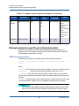
Changing the port mode
You can change the mode of individual ports on an adapter using the following
methods:
BCU commands:
The bcu port - -mode command allows you to change the mode of
individual ports on the adapter.
The bcu adapter - -mode command allows you to change all ports on
the adapter to a specific mode.
HCM Fabric Adapter port menu.
UEFI setup screens for the QLogic BR-Series Adapter. Changing the port
mode through UEFI is only supported on Fabric Adapters.
For more information on using BCU commands and HCM, refer to the QLogic BR
Series Adapter Administrator’s Guide. For more information on using UEFI setup
screens for the QLogic BR-Series Adapter, refer to “Configuring UEFI” on
page 255.
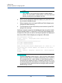
As general steps to change a port’s operating mode, perform the following steps:
1.
Change the mode using BCU commands, HCM, or UEFI setup screens.
2.
Make sure the appropriate SFP (FC or 10 GbE) transceiver and driver
packages are installed to operate the port in the selected mode if they are
not already installed. Refer to Table 1-10 on page 83 for information on
drivers.
3.
Power-cycle the host system.
Dynamically changing the port mode is equivalent to plugging in a new
device in the system, so the system must be power-cycled for this
configuration change to take effect.
4
BR0054504-00 A
1–Product Overview
Fabric Adapters
NOTE
For Windows® systems, you must install the drivers for the new mode after
the system is power-cycled. This is not required if the appropriate driver is
already preinstalled in the system.
When you change the port mode, the port resets to factory defaults for physical
functions (PFs) associated with the mode (refer to “Factory default PF
configurations” on page 28). For details on configuring ports for different operating
modes, refer to the QLogic BR Series Adapter Administrator’s Guide.
NOTE
The BR-1860 Adapter may be ordered with Fibre Channel or 10GbE
transceivers. Depending on the transceiver installed, the port function may be
set to a specific operating mode, such as HBA, NIC, or CNA. In some cases,
the adapter may only support a specific operating mode and cannot be
changed. Refer to your adapter provider for details.
Hardware compatibility
This section outlines important compatibility information.
SFP transceivers (stand-up adapters)
Use only the QLogic-branded small form-factor pluggable (SFP) transceivers
described in this section for stand-up QLogic Fabric Adapters.
5
BR0054504-00 A
1–Product Overview
Fabric Adapters
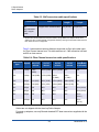
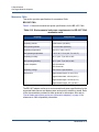
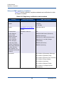
Ports configured in CNA or NIC mode
Table 1-1 provides the type, description, and switch compatibility information for
supported SFP transceivers that can be installed in ports configured in CNA or
NIC mode.
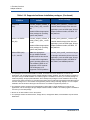
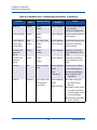
Table 1-1. Compatible SFP transceivers for ports configured in CNA
or NIC mode
SFP transceiver type
Description
Switch compatibility
10 Gbps SR (short
range) SFP+
transceiver, 1490 NM
Optical short range SFP+
transceiver. Distance
depends on cable type.
Refer to “Cabling (stand-up
adapters)” on page 272.
Any switch compatible with
the adapter
10 Gbps LR (long range)
SFP+ transceiver, 10
km. 1310 NM
Optical long range SFP+
transceiver for fiber-optic
cable 10 km (6.2 mi.)
Any switch compatible with
the adapter
1 meter direct-attached
SFP+ transceiver copper
cable
SFP+ transceiver with
twinaxial copper cable
1-meter (3.2 feet) maximum
Any switch compatible with
the cable.
3 meter direct-attached
SFP+ transceiver copper
cable
SFP+ transceiver for
twinaxial copper cable 3
meters (9.8 feet) maximum
Any switch compatible with
the cable.
5 meter direct-attached
SFP+ transceiver copper
cable
SFP+ transceiver for
twinaxial copper cable 5
meters (16.4 feet) maximum
Any switch compatible with
the cable.
NOTE
For adapters releases 3.0.3.0 and later, QLogic BR-Series Adapters allow
non-Brocade active twinaxial cables (based on supported switches),
although non-Brocade cables have not been tested.
6
BR0054504-00 A
1–Product Overview
Fabric Adapters
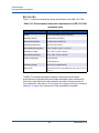
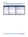
Ports configured in HBA mode
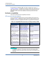
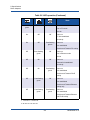
Table 1-2 provides the type, description, and switch compatibility information for
supported SFP transceivers that can be installed in ports configured in HBA
mode.
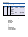
Table 1-2. Compatible SFP transceivers for ports configured in HBA
mode
Type
8 Gbps SWL (short wave
laser) SFP+ transceiver
Description
SFP+ transceiver for fiber-optic
cable
Switch Compatibility
Any switch compatible
with the adapter
Distance depends on cable type.
Refer to “Cabling (stand-up
adapters)” on page 272.
8 Gbps LWL (long wave
laser) 10 km SFP+
transceiver
SFP+ transceiver for fiber-optic
cable
16 Gbps SWL (short
wave laser) SFP+
transceiver
SFP+ transceiver for fiber-optic
cable
16 Gbps LWL (long
wave laser) 10 km SFP+
transceiver
SFP+ transceiver for fiber-optic
cable
Any switch compatible
with the adapter
Distance depends on cable type.
Refer to “Cabling (stand-up
adapters)” on page 272.
Any switch compatible
with the adapter
Distance depends on cable type.
Refer to “Cabling (stand-up
adapters)” on page 272.
Any switch compatible
with the adapter
Distance depends on cable type.
Refer to “Cabling (stand-up
adapters)” on page 272.
7
BR0054504-00 A
1–Product Overview
Fabric Adapters
PCI express connections
QLogic Fabric Adapters are compatible with PCI express (PCIe) connections that
have the following specifications:
x8 lane or greater transfer interface.
Gen1 (PCI Base Specification 1.0, 1.01a, and 1.1).
Gen2 (PCI Express Base Specification 2.0).
Gen3 (PCI Express Base Specification 3.0)
NOTE
Install adapters in PCI express connectors with an x8 lane transfer interface
or greater for best performance. You cannot install Fabric Adapters in PCI or
PCI-X connectors.
Host systems and switches
Support for Fabric Adapter ports depends on the mode (CNA, HBA, or NIC) in
which they are configured:
Ports on Fabric Adapters configured in CNA mode can connect to Fibre
Channel SANs and Ethernet data networks through a compatible switch that
supports Data Center Bridging (DCB) These ports can also connect to a
standard Ethernet LAN switch.
Ports configured in HBA mode support Fabric OS® and connect to SANs
through fabric switches or connect directly to Fibre Channel storage arrays.
Ports configured in NIC mode fully support the Ethernet protocol and
connect directly to the Ethernet LAN.
Storage systems
Using Fabric Adapter ports configured in HBA mode, you can connect a server
(host system) to a Fibre Channel SAN in a switched fabric and point-to-point
topology or directly to a storage array in a point-to-point or Fibre Channel
Arbitrated Loop (FC-AL) topology.
Using Fabric Adapter ports configured in CNA mode, you can connect a server
(host system) to a Fibre Channel SAN through connection with a switch that
supports Data Center Bridging (DCB).
8
BR0054504-00 A
1–Product Overview
Converged Network Adapters
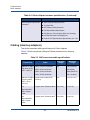
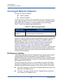
Converged Network Adapters
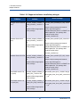
Table 1-3 describes available QLogic FCoE PCIe Converged Network Adapters
(CNAs) for PCIe x8 host bus interfaces, hereafter referred to as QLogic CNAs.
These adapters provide reliable, high-performance host connectivity for
mission-critical SAN environments. Provided in the table are the model number,
port speed, number of ports, and adapter type for each CNA.
Table 1-3. QLogic Fibre Channel CNAs
Model number
Port speed
Number of ports
Adapter type
BR-1007
10 Gbps maximum
2
Mezzanine
BR-1020
10 Gbps maximum
2
Stand-up
BR-1741
10 Gbps maximum
2
Mezzanine
Two types of CNAs are available:
Stand-up adapters.
These are low-profile MD2 form factor PCI Express (PCIe) cards, measuring
16.76 cm by 6.89 cm (6.6 in. by 2.71 in.) that install in PCIe connectors in
standard host systems.
Mezzanine adapters.
These are smaller cards that mount on server blades that install in blade
system enclosures. The enclosures contain other system blades, such as
switch and pass-through modules.
CNA ports connect to a switch that supports Data Center Bridging (DCB). CNAs
combine the functions of a host bus adapter and Network Interface Card (NIC) on
one PCIe x8 card. The CNAs even appear as network interface cards (NICs) and
Fibre Channel adapters to the host. These CNAs fully support FCoE protocols
and allow Fibre Channel traffic to converge onto 10 Gbps Data Center Bridging
(DCB) networks. FCoE and 10 Gbps DCB operations run simultaneously.
The combined high performance and proven reliability of a single-ASIC design
makes these CNAs ideal for connecting host systems on Ethernet networks to
SAN fabrics based on QLogic Fabric or M-Enterprise operating systems.!
9
BR0054504-00 A
1–Product Overview
Converged Network Adapters
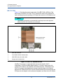
Stand-up adapters
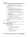
Stand-up type CNAs, such as the BR-1020, are low-profile MD2 form factor PCI
Express (PCIe) cards that install in standard host computer systems. Figure 1-2
on page 10 illustrates major components of the BR-1020 stand-up CNA with two
fiber optic small form factor pluggable (SFP) transceivers installed. Both stand-up
CNAs also support direct-attached SFP+ transceiver copper cables.
NOTE
The following illustration is representative and may have minor physical
differences from the card that you purchased.
1
2
3
6
4
5
1
LEDs for port 1 SFP transceiver
2
Cable connectors for port 1 and port 0 SFP transceivers (Fiber-optic SFP transceiver illustrated)
3
LEDs for port 0 SFP transceiver
4
Low-profile mounting bracket.
Note: The CNA ships with the low-profile mounting bracket installed.
5
PCIe x8 connector
6
ASIC
Figure 1-2. BR-1020 stand-up CNA with low-profile mounting bracket (heat sink
removed)
10
BR0054504-00 A
1–Product Overview
Converged Network Adapters
NOTE
Use only QLogic-branded SFP+ laser transceivers supplied with stand-up
CNAs.
Mezzanine adapters
Mezzanine adapters are smaller modules than stand-up models. These mount on
server blades that install in blade system enclosures.
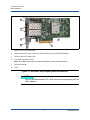
BR-1007 CNA
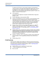
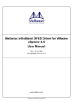
Figure 1-3 illustrates major components of the BR-1007, which is an IBM combo
form factor horizontal (CFFh) CNA containing two ports operating at 10 Gbps.
NOTE
The following illustration is representative and may have minor physical
differences from the card that you purchased.
11
BR0054504-00 A
1–Product Overview
Converged Network Adapters
1
ASIC with heat sink
2
x8 PCIe interface connector.
3
Release lever. Pull to release adapter from blade server.
4
Holes for guiding card onto blade server system board mounting posts.
5
Holes for guiding card onto blade server system board mounting posts.
6
Midplane connectors
Figure 1-3. BR-1007 CNA
NOTE
Labels showing the part number, PWWNs, port MAC addresses, model
number, and serial number for the BR-1007 CNA are on the reverse (top) side
of the card.
12
BR0054504-00 A
1–Product Overview
Converged Network Adapters
The BR-1007 mounts on a server blade that installs in an IBM BladeCenter®
enclosure. The adapter uses FCoE to converge standard networking and storage
data onto a shared Ethernet link. Ethernet and Fibre Channel communications are
routed through the DCB ports on the adapter to the blade system enclosure
midplane, and then onto switch modules installed in the enclosure.
For information on installing the BR-1007 CNA on a server blade, refer to 2,
“Hardware Installation”. For additional information related to the supported blade
server, blade system enclosure, and other devices installed in the enclosure such
as I/O modules and switch modules, refer to the installation instructions provided
with these products.
WoL and SoL limitations
The following describes limitations of support for Wake on LAN (WoL) and Serial
over LAN (SoL) for the BR-1007 adapter:
WoL. The adapter does not support WoL over its 10 GbE links. WoL is
supported using the IBM BladeCenter 1 GbE NIC included on the IBM
server blades.
SoL. The adapter does not support SoL over its 10 GbE links. SoL is
supported using the IBM 1 GbE NIC included on the IBM server blades.
13
BR0054504-00 A
1–Product Overview
Converged Network Adapters
BR-1741 CNA
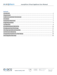
Figure 1-4 illustrates the major components of the BR1741M-k 2P Mezz Card,
also known as the BR-1741 CNA. This is a small form factor (SFF) mezzanine
card containing two ports operating at 10 Gbps that mounts on a Dell blade server.
NOTE
The following illustration is representative and may have minor physical
differences from the card that you purchased.
1
ASIC with heat sink
2
Port WWN and MAC address label
3
OEM PPID and part number label
4
QLogic serial number label
Figure 1-4. BR-1741 mezzanine card
The BR-1741 mounts on supported blade servers that install in Dell™
PowerEdge™ M1000e modular blade systems. It is used in conjunction with
matching I/O modules, also installed in the blade enclosure. The adapter uses
FCoE to converge standard data and storage networking data onto a shared
Ethernet link. Ethernet and Fibre Channel communications are routed through the
DCB ports on the adapter to the enclosure backplane, and then to the I/O module.
14
BR0054504-00 A
1–Product Overview
Converged Network Adapters
For information on installing the BR-1741 CNA on a blade server, refer to 2,
“Hardware Installation”. For additional information related to the supported server
blade, blade enclosure, and other devices installed in the enclosure such as I/O
and switch modules, refer to the installation instructions provided with these
products.
Hardware compatibility
This section outlines important compatibility information.
SFP transceivers (stand-up adapters)
Use only the Brocade-branded small form-factor pluggable (SFP) transceivers
described in Table 1-4 in BR-Series stand-up CNAs. The table provides the type,
description, and switch compatibility information for supported SFP transceiver.
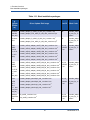
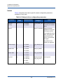
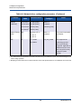
Table 1-4. Compatible SFP transceivers for QLogic stand-up CNAs
SFP transceiver type
Description
Switch compatibility
10 Gbps SR (short
range) SFP+
transceiver, 1490 NM
Optical short range SFP+
transceiver for Distance
depends on cable type.
Refer to “Cabling (stand-up
adapters)” on page 282.
Any switch compatible with
the adapter
10 Gbps LR (long range)
SFP+ transceiver, 10
km, 1310 NM
Optical long range SFP+
transceiver for fiber optic
cable 10 km (6.2 mi.)
Any switch compatible with
the adapter
1 meter direct-attached
SFP+ transceiver copper
cable
SFP+ transceiver with
twinaxial copper cable 1
meter (3.2 feet) maximum
Any switch compatible with
the cable.
3 meter direct-attached
SFP+ transceiver copper
cable
SFP+ transceiver with
twinaxial copper cable 2
meters (9.8 feet) maximum
Any switch compatible with
the cable.
5 meter direct-attached
SFP+ transceiver copper
cable
SFP+ transceiver with
twinaxial copper cable 5
meters (16.4 feet) maximum
Any switch compatible with
the cable.
NOTE
For adapters releases 3.0.3.0 and later, active twin-axial copper cables
supplied by vendors other than QLogic can be used, but the cables are not
supported.
15
BR0054504-00 A
1–Product Overview
Converged Network Adapters
Host systems and switches (stand-up adapters)
QLogic CNAs must connect to Fibre Channel SANs and Ethernet data networks
through a compatible switch that supports Data Center Bridging (DCB).
Server blades and system enclosures (mezzanine adapters)
Consider the following points when installing mezzanine adapters in blade servers
and system enclosures or chassis:
For information about the system enclosures and enclosure components,
such as server blades, I/O modules, switch modules, and optional devices
that are compatible with the adapter, visit the manufacturer websites for
these products. You can also contact your server blades or system
enclosure marketing representative or authorized reseller.
To support each I/O module that you install in the system enclosure, you
may also need to install a compatible adapter in each server blade that you
want to communicate with the I/O module. Also, the adapter may only
support switch modules or blades in specific I/O bays of the enclosure. For
additional information, refer to installation and user guides and the
interoperability guides provided for the blade server and system enclosure.
The QLogic mezzanine adapter is compatible with the following types of
modules that install in the supported blade system enclosure:
Pass-thru modules
I/O modules
Switch modules
NOTE
For detailed information about these modules, see the installation and
user guides and interoperability guides provided for these modules and
the blade system enclosure.
The maximum number of adapters that you can install in the system
enclosure varies according to the type of enclosure that you are using
because each type may support a different number of server blades. For
additional compatibility information, see the installation, user, and
interoperability guides provided for the blade server and the system
enclosure.
16
BR0054504-00 A
1–Product Overview
Converged Network Adapters
PCI express connections
QLogic CNAs are compatible with PCI express (PCIe) connections that have the
following specifications:
x8 lane or greater transfer interface
Gen1 (PCI Base Specification 1.0, 1.01a, and 1.1)
Gen2 (PCI Express Base Specification 2.0)
Gen3 (PCI Express Base Specification 3.0)
NOTE
Install CNAs in PCI express connectors with an x8 lane transfer interface or
greater for best performance. You cannot install CNAs in PCI or PCI-X
connectors.
Storage systems
Using QLogic CNAs, you can connect a server (host system) to a Fibre Channel
SAN through connection with a compatible switch that supports Data Center
Bridging (DCB).
NOTE
The CNA can connect with a network switch and perform NIC functions for
network traffic.
17
BR0054504-00 A
1–Product Overview
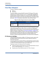
Host Bus Adapters
Host Bus Adapters
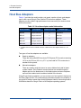
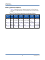
Table 1-5 provides the model number, port speed, number of ports, and adapter
type for the current QLogic Fibre Channel PCIe host bus adapters. These
adapters provide reliable, high-performance host connectivity for mission-critical
SAN environments.
Table 1-5. Host bus adapter model information
Model number
Port speed
Number of ports
Adapter type
BR-804
8 Gbps maximum
2
Mezzanine
BR-815
8 Gbps maximum1
1
Stand-up
BR-825
8 Gbps maximum1
2
Stand-up
BR-1867
16 Gbps maximum
2
Mezzanine
BR-1869
16 Gbps maximum
4
Mezzanine
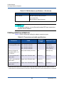
1. A 4 Gbps SFP transceiver installed in BR-815 or BR-825 host bus adapters allows 4, 2, or 1
Gbps.
Two types of host bus adapters are available:
Stand-up adapters.
These are low-profile MD2 form factor PCI Express (PCIe) cards, measuring
16.76 cm by 6.89 cm (6.6 in. by 2.71 in), that install in PCIe connectors in
standard host systems.
Mezzanine adapters.
These are smaller cards that mount on server blades that install in blade
system chassis. Fibre Channel communications are routed through the
adapter ports on the blade server to the blade system enclosure midplane
and onto the installed switch modules installed in the chassis.
Using QLogic host bus adapters, you can connect your host system to devices on
the Fibre Channel SAN. The combined high performance and proven reliability of
a single-ASIC design makes these host bus adapters ideal for connecting hosts to
SAN fabrics based on QLogic Fabric or M-Enterprise operating systems.
18
BR0054504-00 A
1–Product Overview
Host Bus Adapters
Stand-up adapters
Figure 1-5 illustrates major components of the BR-825 stand-up model host bus
adapter.
NOTE
The following illustration is representative and may have minor physical
differences from the host bus adapter that you purchased.
1
LEDs for port 1 SFP transceiver
2
Fiber-optic cable connectors for port 1 and port 0 SFP transceivers
3
LEDs for port 0 SFP transceivers
4
Low-profile mounting bracket.
Note: The host bus adapter ships with the low-profile mounting bracket installed.
5
PCIe x8 PCIe connector
6
ASIC
7
Serial number label
8
Label showing PWWN for each port.
Figure 1-5. BR-825 Host bus adapter with low-profile mounting bracket (heat sink
removed)
19
BR0054504-00 A
1–Product Overview
Host Bus Adapters
NOTE
Use only Brocade-branded SFP laser transceivers supplied with stand-up
adapters.
Mezzanine adapters
Mezzanine Fabric Adapters are smaller than stand-up modules. For example, the
BR-804 adapter measures approximately 4 in. by 4.5 in. (10.16 cm by 11.43 cm).
Mezzanine adapters mount in blade servers that install in supported blade system
chassis. Refer to the “Server blades and system enclosures (mezzanine
adapters)” on page 16 for references for Fabric Adapter compatibility information.
Note that mezzanine Fabric Adapters do not have external port connectors with
optics such as stand-up adapters, but internal ports that connect to switch and I/O
modules installed in the blade system chassis through high-speed links in the
internal chassis or enclosure backplane.
Three models of host bus mezzanine adapters are available:
BR-804
BR-1867
BR-1869
20
BR0054504-00 A
1–Product Overview
Host Bus Adapters
BR-804 host bus adapter
Figure 1-6 illustrates major components of the BR-804 mezzanine host bus
adapter. This mezzanine card installs in supported blade servers that install in
Hewlett Packard® BladeSystem® c-Class enclosures.
NOTE
The following illustration is representative and may have minor physical
differences from the host bus adapter that you purchased.
1
Mounting screws
2
ASIC
3
OEM serial and part number
4
PWWNs for adapter ports
5
QLogic serial and part number
Figure 1-6. BR-804 mezzanine host bus adapter
21
BR0054504-00 A
1–Product Overview
Host Bus Adapters
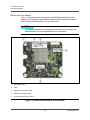
BR-1867 host bus adapter
Figure 1-7 illustrates major components of the BR-1867, an host bus adapter
mezzanine adapter containing two Fibre Channel ports operating at 16 or 8 Gbps.
The adapter measures 10.65 cm (4.19 inches) deep, 8.49 cm (3.34 inches) wide,
and 4.15 cm (1.64 inches) high.
NOTE
The following illustration is representative and may have minor physical
differences from the card that you purchased.
1
x8 PCIe interface connector
2
ASIC with heat sink
3
Connector guide
4
Midplane connector
Figure 1-7. BR-1867 host bus adapter (bottom view)
NOTE
Labels showing the part number, PWWNs, model number, and serial number
for the BR-1867 host bus adapter are on the top side of the card (reverse from
side shown in previous illustration).
22
BR0054504-00 A
1–Product Overview
Host Bus Adapters
The BR-1869 Adapter provides four Fibre Channel connections capable of
providing 8 Gbps or 16 Gbps to devices on Fibre Channel (FC) SANs. Depending
on the system configuration, the adapter provides up to 16 Gbps of full-duplex
line-rate bandwidth per port.
The BR-1867 mounts on a compute node that installs in an IBM Flex System®
chassis. Mezzanine adapters do not have external SFP transceivers and port
connectors. Fibre Channel communications are routed through the internal ports
on the adapter to the chassis midplane, and then onto switch modules installed in
the chassis.
For information on installing the BR-1867 host bust adapter on a compute node,
refer to 2, “Hardware Installation”. For additional information related to the
supported compute node and other devices installed in the system chassis such
as I/O modules and switch modules, refer to the installation instructions provided
with these products.
23
BR0054504-00 A
1–Product Overview
Host Bus Adapters
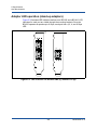
BR-1869 host bus adapter
Figure 1-8 illustrates major components of the BR-1869, The adapter measures
157.9 mm (6.22 inches) deep, 107.8 mm (4.24 inches) wide, and 36.4 mm (1.43
inches) high.
NOTE
The following illustration is representative and may have minor physical
differences from the card that you purchased.
1
ASIC with heat sink
2
x8 PCIe interface connector
3
ASIC with heat sink
4
Midplane connector
Figure 1-8. BR-1869 Host bus adapter (bottom view)
NOTE
Labels showing the part number, PWWNs, model number, and serial number
for the BR-1869 host bus adapter are on the top side of the card (reverse from
side shown in previous illustration).
24
BR0054504-00 A
1–Product Overview
Host Bus Adapters
The BR-1869 Adapter provides four Fibre Channel connections capable of
providing 8 Gbps or 16 Gbps to devices on Fibre Channel (FC) SANs. Depending
on the system configuration, the adapter provides up to 16 Gbps of full-duplex
line-rate bandwidth per port.
The BR-1869 mounts on a compute node that installs in an IBM Flex System
chassis. Mezzanine adapters do not have external SFP transceivers and port
connectors. Fibre Channel communications are routed through the internal ports
on the adapter to the chassis midplane, and then onto switch modules installed in
the chassis.
The adapter contains two ASICs, each controlling two FC ports. These ports are
split between two different compute nodes to provide dual, redundant paths
between two switch elements. Adapter properties on a specific compute node will
list only two available ports.
For information on installing the BR-1869 host bus adapter on a compute node,
refer to Chapter 2, "Hardware Installation". For additional information related to
the supported compute node and other devices installed in the system chassis
such as I/O modules and switch modules, refer to the installation instructions
provided with these products.
Hardware compatibility
This section outlines important compatibility information.
SFP transceivers (stand-up adapters)
Use only QLogic-branded small form factor pluggable (SFP) fiber optic 4 Gbps
and 8 Gbps transceivers in the QLogic Fibre Channel stand-up host bus adapters.
NOTE
All BR-815 and BR-825 host bus adapters ship with the 8 Gbps SFP+
transceivers.
Host systems and switches (stand-up adapters)
QLogic host bus adapters connect to Fibre Channel SANs through compatible
fabric switches or connect directly to Fibre Channel storage arrays.
Server blades and system enclosures and chassis (mezzanine adapters)
Consider the following information when installing and using QLogic host bus
adapter mezzanine adapters.
25
BR0054504-00 A
1–Product Overview
Host Bus Adapters
BR-804 host bus adapters
The BR-804 mezzanine host bus adapter is compatible with blade servers, switch
modules, interconnect modules, and other components that install in supported
blade system enclosures. For details on blade servers and system enclosures that
are compatible with this adapter, refer to the following:
Manufacturer web sites for these products.
Your blade server or blade system enclosure marketing representative or
authorized reseller.
Documentation provided for your blade server, blade system enclosure, and
enclosure components.
BR-1867 and BR-1869 host bus adapter
Consider the following points when installing these mezzanine adapters in
compute nodes and Flex System chassis:
Visit the manufacturer web sites for these products. In addition, you can also
contact your compute node or system chassis marketing representative or
authorized reseller.
These mezzanine adapters are compatible with the devices that install in the
supported system chassis such as the following:
Compute nodes
Pass-thru modules
I/O modules
Switch modules
NOTE
For detailed information about these modules, see the installation and
user guides and interoperability guides provided for these modules and
the blade system enclosure.
The maximum number of adapters that you can install on a compute node or
in the system chassis varies according to the type of chassis that you are
using because each type of chassis may support a different number of
compute nodes. For additional compatibility information, see the installation,
user, and interoperability guides provided for the compute node and the
system chassis.
Use only driver update disk version 3.0.3.0 or later for compute nodes with
the BR-1867 Fabric Adapter installed.
Use only driver update disk version 3.2.1.0 or later for compute nodes with
the BR-1869 Fabric Adapter installed.
26
BR0054504-00 A
1–Product Overview
Adapter features
PCI express connections
The QLogic Fibre Channel host bus adapters are compatible in PCI express
(PCIe) connectors with the following specifications:
x8 lane or greater transfer interface.
Gen1 (PCI Base Specification 1.0, 1.01a, and 1.1).
Gen2 (PCI Express Base Specification 2.0).
Gen3 (PCI Express Base Specification 3.0).
NOTE
Install host bus adapters in PCI express (PCIe) connectors with an x8 lane
transfer interface or greater for best performance. You cannot install host bus
adapters in PCI or PCIx slots.
Storage systems
Using QLogic host bus adapters, you can connect a server (host system) to a
Fibre Channel SAN in a switched fabric and point-to-point topology or directly to a
storage array in a point-to-point topology.
Adapter features
QLogic BR-Series Adapters support the following general features for enhanced
performance and connectivity in the SAN and Ethernet networks. For limitations
and considerations for feature support for specific operating systems, refer to
“Operating system considerations and limitations” on page 61.
Fabric Adapters - Also refer to the following subsections depending on the
port mode and SFP transceiver configurations:
“I/O virtualization” on page 28.
“Additional general features” on page 31
“FCoE features” on page 34, for ports configured in CNA mode.
“Data Center Bridging and Ethernet features” on page 38, for ports
configured in CNA or NIC modes.
“Host bus adapter features” on page 49, for ports configured in HBA
mode.
27
BR0054504-00 A
1–Product Overview
Adapter features
CNAs - Also refer to the following subsections:
“I/O virtualization” on page 28.
“Additional general features” on page 31
“FCoE features” on page 34.
“Data Center Bridging and Ethernet features” on page 38.
Host bus adapters - Also refer the following subsections:
“I/O virtualization” on page 28.
“Additional general features” on page 31
“Host bus adapter features” on page 49.
I/O virtualization
QLogic BR-Series Adapters support physical function-based I/O virtualization to
provide data isolation and sharing of the bandwidth resources. Depending on the
adapter model or the operating mode (CNA, HBA, or NIC) assigned to Fabric
Adapter ports, from one to eight functions can be supported per port on the PCI
bus. These physical functions (PFs) can be seen as multiple adapters by the host
operating system or hypervisor.
Factory default PF configurations
For each type of adapter, each port has a set base or default physical function
(PF) as follows:
For host bus adapter models, each port has one Fibre Channel (FC)
function.
For CNA models, each port has one FCoE function and one Ethernet
function.
For Fabric Adapters, the default number of PFs depends on the mode
configured for the port. Refer to Table 1-6.
Table 1-6. Factory default physical function (PF) configurations for
Fabric Adapter ports.
Mode
PFs configured per port
HBA
1
FC
CNA
2
Ethernet and FCoE
NIC
1
Ethernet
28
PF configuration per port
BR0054504-00 A
1–Product Overview
Adapter features
vHBA
Virtual HBAs (vHBAs) are virtual port partitions that appear as virtual or logical
host bus adapters to the host operating system. vHBA is the default PF
associated with an host bus adapter port, the FCoE function on a CNA port or
Fabric Adapter port configured in CNA mode, or a Fabric Adapter port configured
in HBA mode. Additional vHBAs cannot be configured, and you cannot create or
delete the default vHBA.
HCM discovers and displays all vHBAs as “FC.” For Fabric Adapter ports set in
CNA mode, vHBAs display as “FCoE.”
The following are limitations of vHBAs:
Multiple vHBAs per port are not supported.
Target rate limiting (TRL) and Quality of Service (QoS) are not supported at
the vHBA level (only at the physical port level).
Boot over SAN is not supported at the vHBA level (only at the physical port
level).
vNIC
Virtual Network Interface Cards (vNICs) are virtual port partitions that appear as
virtual or logical NICs to the host operating system. HCM discovers and displays
all vNICs for a physical port as “Eth.”
Following are limitations and considerations for vNICs:
vNICs are supported on QLogic CNAs and on Fabric Adapter 10 GbE ports
configured in CNA or NIC mode.
You can create up to four vNICs on each Fabric Adapter port configured in
NIC mode using the BCU vnic - -create command and through HCM
options. You can delete vNICs using the vnic - -delete command or through
HCM. For each Fabric Adapter port configured in CNA mode, you can only
create up to three Ethernet PFs since the fourth PF must be used for FCoE.
You cannot create or delete vNICs for QLogic CNA models, such as the
BR-1020. Multiple vNICs are not supported on these models.
Due to ESX memory limitations, a total of 4 vNICs in a VMware ESX system
is supported.
vNICs are not supported on QLogic host bus adapter modules.
vNICs are not supported on Solaris® SPARC® systems.
Multiple vNICs are not supported on QLogic CNA models, such as the
BR-1020.
For Windows, teaming is not supported between vNICs configured on the
same physical port.
29
BR0054504-00 A
1–Product Overview
Adapter features
For each vNIC, you can configure bandwidth in increments of 100 Mbps using
BCU commands, HCM, and BIOS/UEFI setup screens. The maximum bandwidth
per vNIC is 10,000 Mbps. The maximum bandwidth per port is also 10,000 Mbps.
Therefore, you can divide the 10,000 Mbps among all PFs configured. For
example, if you configure four Ethernet PFs for a Fabric Adapter port, you can
assign 2,500 Mbps per PF to reach the 10,000 Mbps maximum.
You can configure a minimum available bandwidth per vNIC partition. This
bandwidth is guaranteed to be available on a port when other vNICs are
contending for bandwidth on the port. Note the following for this feature:
A zero value for the minimum bandwidth implies no guaranteed minimum
bandwidth for the vNIC.
The sum of minimum bandwidths for all vNICs on a port should be no more
than the port’s bandwidth.
The minimum bandwidth should be no more than the maximum bandwidth
for the vNIC.
As an example of minimum bandwidth configuration, vNIC1 is configured at 2
Gbps, vNIC2 at 4 Gbps, vNIC3 at 0 Gbps, and vNIC4 at 0 Gbps. In this case,
vNIC1 and vNIC2 are guaranteed a minimum of 2 and 4 Gbps respectively, but no
minimum is guaranteed for vNIC 3 and 4. When all four vNICs are trying to send
data, the following is approximate what you can expect for minimum bandwidth in
the steady state:
vNIC1 = 2 + (10-2-4)/4 = 3 Gbps
vNIC2 = 4 + (10-2-4)/4 = 5 Gbps
vNIC3 = 0 + (10-2-4)/4 = 1 Gbps
vNIC4 = 0 + (10-2-4)/4 = 1 Gbps
vHBA and vNIC BCU commands
Whether a port is configured for a single function or in the case of vNICs, multiple
functions, each PF is assigned a PCI function ID (pcfid). This pcfid is used as a
parameter in BCU commands to configure additional features or display
information for that specific PF. For example, pcfid can be used in certain BCU
debug, authentication, diagnostic, Ethernet port, lport, rport, VLAN, and FCP
initiator mode commands, Specific vNIC and vHBA BCU commands are available
for configuring vHBAs and vNICs. Examples of these commands follow:
vhba - -query <pcifn> - Queries information about the virtual HBA.
vhba - -enable <pcifn> - Enables a vHBA on a specified adapter port for a
specified PF.
vhba – -disable <pcifn> - Disables a vHBA on a specified adapter port for a
specified PCI function.
30
BR0054504-00 A
1–Product Overview
Adapter features
vhba - -stats <pcifn> -Displays statistics for the virtual HBA.
vhba - -statsclr <pcifn> - Resets statistics for the virtual HBA.
For details on using these commands, refer to the QLogic BR Series Adapter
Administrator’s Guide.
Following are available vNIC commands:
vnic - -create <port_id> [-bmin <min_bandwidth>] [-bmax
<max_bandwidth>]- Creates a new vNIC instance for a given adapter port.
You can specify the maximum bandwidth allowable for this vNIC.
vnic - -delete <pcifn> - Removes the specified vNIC instance.
vnic - -query <pcifn> - Queries information about the virtual NIC.
vnic - -enable <pcifn> - Enables a vNIC on a specified adapter port for a
specified PCI function.
vnic - -disable <pcifn> - Disables a vNIC on a specified adapter port for a
specified PCI function.
vnic - -stats <pcifn> - Displays statistics for the virtual NIC.
vnic - -statsclr <pcifn> - Resets vNIC statistics.
vnic - -bw <pcifn> [-bmin <min bandwidth>] [-bmax <max bandwidth>]
per- Modifies the maximum allowable bandwidth for a vNIC.
For details on using these commands, refer to the QLogic BR Series Adapter
Administrator’s Guide.
Virtual port persistency
Virtual port configurations for Linux and Windows systems will persist after the
system reboots or after driver upgrades.
Additional general features
Following are brief descriptions of additional general features supported on all
QLogic BR-Series Adapters:
BIOS and UEFI support:
x86 and x64 Basic Input/Output System (BIOS)
Unified Extensible Firmware Interface (UEFI)
PCI BIOS 3.1 or later
SMBIOS specification version 2.4 or later
Fabric-based boot LUN discovery
Network boot (PXE, UEFI)
31
BR0054504-00 A
1–Product Overview
Adapter features
gPXE support for VMware ESXi 5.x auto-deployment
NOTE
Network boot and gPXE support for VMware ESXi 5.x auto-deployment
are supported only on CNA and NIC only.
I/O Device Management (IODM)
For VMware, events such as RSCN or link state changes are reported to the
operating system for diagnoses of various storage protocol issues.
MultiQueue support
ESXi 5.5 driver supports performance scalability features like MultiQueue.
This allows ESX to distribute incoming I/O on these queues based on CPU
affinity.
The use of multiple queues to send requests and get responses has the
following advantages:
Reduces CPU cost per I/O.
Enhance the performance of storage adapter.
Extended storage request block (SRB)
Windows Server® 2012 uses the small computer system interface (SCSI)
request block or SRB to relay information related to SCSI commands.
Windows versions prior to Windows 2012 have the following limitations:
Only 16-byte command descriptor blocks (CDB) are supported.
There is no support for bi-directional CDBs.
For Windows 2012 and later, support is available for the following:
16-byte CDBs and greater
Bi-directional CDBs
More than 254 I/Os per LUN
New addressing scheme
Human Interface Infrastructure (HII) menu support. These menus are
integrated into the UEFI configuration browser. Options in these menus
allow you to enable, disable, and set port speed for adapter ports. It supports
IBM Agentless Inventory Manager (AIM) framework which queries some of
the host bus adapter properties using a new VFR formset. The support is for
the BR-1867 and BR-1869 adapters only and is limited to retrieving (get)
and not for updating (set) configuration.
32
BR0054504-00 A
1–Product Overview
Adapter features
Host Connectivity Manager (HCM) device management and QLogic
Command Line Utility (BCU) tools for comprehensive adapter management.
Hyper-V®. This consolidates multiple server roles as separate virtual
machines (VMs) using the Windows Server 2008 R2 and later operating
system and provides integrated management tools to manage both physical
and virtual resources.
Management APIs for integration with a management application, such as
Brocade Network Advisor.
PCIe interface with eight lanes. The adapter operates in Gen 1 and Gen 2
server connectors that have the following specifications per lane:
PCIe Gen 2 connector. Transfer rate of 5 Gigatransfers per second
(GT/s) per lane. Data rate of 500 MBps per lane.
PCIe Gen 1 connector. Transfer rate of 2.5 GT/s per lane. Data rate of
250 MBps per lane.
Plug-n-play and power management for all supported operating systems.
RoHS-6. Certification by the European Union Restriction of Hazardous
Substances Directive (RoHS) that adapter hardware components do not
contain any of the six restricted materials. These are mercury, chromium VI,
cadmium, polybrominated biphenyl ether, lead, and polybrominated
biphenyl.
Small form-factor pluggable (SFP+) transceiver optics on stand-up adapters
for enhanced serviceability (stand-up adapters only).
Storage Management Initiative Specification (SMI-S).
Specification supporting the Common Information Model (CIM) Provider,
which allows any standard Common Information Model (CIM) and
SMI-S-based management software to manage installed QLogic BR-Series
Adapters.
NOTE
Although SMI-S Provider and CIM Provider may be used
interchangeably, CIM is the more generic term, while SMI-S is
storage-specific.
Switch fabric topology - CNAs and Fabric Adapter ports configured in CNA
mode can connect to a switch that supports Data Center Bridging (DCB)
through 10 GbE ports.
Synthetic Fibre Channel Ports
33
BR0054504-00 A
1–Product Overview
Adapter features
For Windows 2012 Server, guest operating systems (virtual machines)
running on Hyper-V can detect and manage Fibre Channel ports. The host
bus adapters or Fabric adapter ports configured in HBA mode that are
presented to the virtual machines (VMs) are called “synthetic” FC ports. This
feature is configured through Hyper-V.
UCM compliance
QLogic BR-Series Adapters are compliant with IBM Unified Configuration
Manager (UCM).
Windows Management Instrumentation (WMI).
Windows Preinstallation Environment (WinPE), a minimal operating system
with limited services for Windows Server or Windows Vista® used for
unattended deployment of workstations and servers. WinPE is designed for
use as a standalone preinstallation environment and as a component of
other setup and recovery technologies. WinPE is supported by QLogic
Windows Server 2008 R2 network and storage drivers.
Windows Server 2008 R2 and later, Red Hat Enterprise Linux (RHEL)®,
SUSE Linux Enterprise Server (SLES)®, VMware® ESX Server®, Solaris,
and Oracle Linux (OL). For more details, refer to “Host operating system
support” on page 70.
Windows Server Core, a minimal server option for Windows Server 2008 R2
operating systems that provides a low-maintenance server environment with
limited functionality. All configuration and maintenance is done through
command line interface windows or by connecting to a system remotely
through a management application.
Windows 7. Windows 7 x86 is supported by Windows Server 2008 R2 x86
drivers. Windows 7 x64 is supported by Windows Server 2008 R2 x64
drivers.
Windows Server 2012.
FCoE features
CNAs and Fabric Adapter ports configured in CNA mode support the following
Fibre Channel over Ethernet (FCoE) features. For limitations and considerations
for feature support for specific operating systems, refer to “Operating system
considerations and limitations” on page 61.
500,000 IOPS per port for maximum I/O transfer rates.
10 Gbps throughput per port full duplex.
Boot over SAN.
34
BR0054504-00 A
1–Product Overview
Adapter features
This feature provides the ability to boot the host operating system from a
boot device located somewhere on the SAN instead of the host’s local disk
or directly attached Fibre Channel storage. Specifically, this “boot device” is
a logical unit number (LUN) located on a storage device.
Fabric-based boot LUN discovery is a feature that allows the host to obtain
boot LUN information from the fabric zone database.
NOTE
Fabric-based boot LUN discovery is not available for direct-attached
targets.
Fibre Channel-Security Protocol (FC-SP) provides device authentication
through key management.
FCoE Initialization Protocol (FIP) support for the following:
FIP 2.0
preFIP and FIP 1.03
FIP Discovery protocol for dynamic FCF discovery and FCoE link
management
FPMA type FIP fabric login
VLAN discovery for untagged and priority tagged FIP frames
FIP discovery solicitation and FCP discovery
Login (FIP and FCoE)
FIP link down handling.
FIP version compatibility
FIP keep alive
FIP clear virtual links
NOTE
The CNA FIP logic automatically adapts to the adequate FIP version
and preFIP to enable backward compatibility.
Interrupt coalescing
35
BR0054504-00 A
1–Product Overview
Adapter features
This feature provides a method to delay generation of host interrupts and
thereby combine (coalesce) processing of multiple events. This reduces the
interrupt processing rate and reduces the time that the CPU spends on
context switching. You can configure the following parameters per port to
adjust interrupt coalescing:
Interrupt time delay. There is a time delay during which the host
generates interrupts. You can increase this delay time and thereby
coalesce multiple interrupts events into one. This results in fewer
interrupts for interrupt events.
Interrupt latency timer. An interrupt is generated when no new reply
message requests occur after a specific time period. You can adjust
this time period and thereby minimize I/O latency.
I/O execution throttle
Refer to “I/O execution throttle” under “Host bus adapter features” on
page 49.
LUN masking.
LUN masking establishes access control to shared storage to isolate traffic
between different initiators that are zoned in with the same storage target.
LUN masking is similar to zoning, where a device in a specific zone can
communicate only with other devices connected to the fabric within the
same zone. With LUN masking, an initiator port is allowed to access only
those LUNs identified for a specific target.
Enable LUN masking on an adapter physical port through the HCM Basic
Port Configuration dialog box and the BCU fcpim –lunmaskadd
command to identify the logical port (initiator) and remote WWN (target) for
the LUN number. Refer to the QLogic BR Series Adapter Administrator’s
Guide for more information on configuration.
You can also enable LUN masking through the QLogic BIOS Configuration
Utility and your system’s UEFI setup screens. Refer to “Configuring BIOS
with the BIOS Configuration Utility” on page 246 and “Configuring UEFI” on
page 255.
This feature has the following limitations:
Only 16 LUN masking entries are allowed per physical port.
Multiple BCU instances for adding and deleting LUN masking are not
supported.
This feature is only supported on QLogic host bus adapters and Fabric
Adapters.
36
BR0054504-00 A
1–Product Overview
Adapter features
You can configure LUN masking for a particular target even without the
actual devices being present in the network.
When configuring boot over SAN, mask the boot LUN so that the initiator
has exclusive access to the boot LUN. Refer to the QLogic BR Series
Adapter Administrator’s Guide for more information.
N_Port ID Virtualization (NPIV). This allows multiple N_Ports to share a
single physical N_Port. This allows multiple Fibre Channel initiators to
occupy a single physical port and reduce SAN hardware requirements.
Persistent binding enables you to permanently assign a system SCSI target
ID to a specific Fibre Channel device. This is applicable for Windows
operating systems only.
Simple Network Management Protocol (SNMP)
SNMP is an industry-standard method of monitoring and managing network
devices. QLogic CNA adapters and Fabric Adapter ports configured in CNA
mode provide agent and MIB support for SNMP. For more information, refer
to “Simple Network Management Protocol” on page 67.
SRB support
Refer to “SRB support” under “Additional general features” on page 31.
Target rate limiting. You can enable or disable this feature on specific ports.
Target rate limiting relies on the storage driver to determine the speed
capability of discovered remote ports, and then uses this information to
throttle the FCP traffic rate to slow-draining targets. This reduces or
eliminates network congestion and alleviates I/O slowdowns at faster
targets.
Target rate limiting is enforced on all targets that are operating at a speed
lower than that of the target with the highest speed. If the driver is unable to
determine a remote port’s speed, 1 Gbps is assumed. You can change
default speed using BCU commands. Target rate limiting protects only FCP
write traffic.
vHBA
Virtual HBAs (vHBAs) are virtual port partitions that appear as virtual or
logical HBAs to the host operating system. Multiple vHBAs are not
supported, so you cannot create or delete them from an adapter. For more
information, refer to“I/O virtualization” on page 28.
37
BR0054504-00 A
1–Product Overview
Adapter features
Data Center Bridging and Ethernet features
QLogic CNAs and Fabric Adapter ports configured in CNA or NIC mode support
the following Data Center Bridging (DCB) and Ethernet networking features. For
limitations and considerations for feature support for specific operating systems,
refer to “Operating system considerations and limitations” on page 61.
10 Gbps throughput per port full duplex.
1500 or 9600 byte (jumbo) frames
These frames allow data to be transferred with less effort, reduce CPU
utilization, and increase throughput. Mini-jumbo frames (2500 bytes) are
required to encapsulate FCoE frames on DCB. Network administrators can
change the jumbo packet size from the default setting using host operating
system commands as described in A, “Adapter Configuration”. Note that the
MTU size refers to the MTU for network configuration only. Internally,
hardware will always be configured to support FCoE frames that require
mini-jumbo size frames.
NOTE
The jumbo frame size set for the network driver cannot be greater than
the setting on the attached switch that supports Data Center Bridging
(DCB) or the switch cannot accept jumbo frames.
Brocade Network Intermediate Driver (BNI)
This provides support for multiple VLANs on ports and teams on 2008 R2
systems. This driver is installed with the adapter software.
NOTE
For Windows Server 2012, the BNI driver is not installed because
VLANs are natively supported by the Windows 2012 operating system.
Checksum/CRC offloads for FCoE packets, IPv4/IPv6 TCP and UDP
packets, and IPv4 header.
The checksum offload supports Checksum offloads for TCP and UDP
packets and the IPv4 header. This enables the CNA to compute the
checksum, which saves host CPU cycles. The CPU utilization savings for
TCP checksum offload can range from a few percent with an MTU of 1500,
and up to 10-15 percent for an MTU of 9000. The greatest savings are
provided for larger packets.
38
BR0054504-00 A
1–Product Overview
Adapter features
Configurable Max NetQueue
By reducing the number of NetQueues, MSI vectors are reduced for installed
adapter ports. With many adapters, a high number of MSI-X vectors on ESX
platforms can cause poor performance and cause adapters to run in INTx
mode. Using new bnad (QLogic network adapter driver) parameters, the
driver can set NetQueue limits and allocate MSI-X vectors according to
these limits. For Max NetQueue configuration values, refer table “Network
driver module parameters” on page 344.
Data Center Bridging Capability Exchange Protocol (DCBCXP) (IEEE 802.1
standard)
DCBCXP is used between the CNA or Fabric Adapter port configured in
CNA mode and the switch that supports Data Center Bridging (DCB) to
exchange configuration with directly connected peers. DCBCXP uses LLDP
to exchange parameters between two link peers.
Enhanced transmission selection (IEEE 802.1Qaz standard)
ETS provides guidelines for creating priority groups to enable guaranteed
bandwidth per group. More important storage data traffic can be assigned
higher priority and guaranteed bandwidth so it is not stalled by
less-important traffic.
Ethernet flow control
Ethernet flow control is a mechanism for managing data transmission
between two network nodes to prevent a fast sender from overrunning a
slow receiver. When an overwhelmed receiver generates a PAUSE frame,
this halts transmission for a specified period of time. Traffic resumes when
time specified in the frame expires or PAUSE zero is received.
Flexible MAC address
Flexible MAC address based classification of inbound packets for
virtualization functions. This provides security for these functions by isolating
virtual machines from each other and controlling the resources they access.
gPXE
This is an open source feature that allows systems without network PXE
support to boot over the network. It enhances existing PXE environments
using Trivial File Transfer Protocol (TFTP) with additional protocols such as
Domain Name System (DNS), Hypertext Transfer Protocol (HTTP), and
Internet Small Computer System Interface (iSCSI). VLAN tagging is also
enabled. For more information, refer to “gPXE boot” on page 202.
39
BR0054504-00 A
1–Product Overview
Adapter features
Hypervisor
Hypervisor (Hyper-V) is a processor-specific virtualization platform that
allows multiple operating systems to share a single server platform. Refer to
“Host operating system support” on page 70 for a list of operating systems
that support hypervisor operation for QLogic BR-Series Adapters.
IBM Virtual Fabric support
IBM Virtual Fabric, or vNIC, is supported on QLogic CNAs and Fabric
Adapter ports configured in CNA or NIC mode. IBM Virtual Fabric is a switch
agnostic NIC partitioning feature that enforces a minimum guaranteed
bandwidth for vNICs. Using BCU commands, you can specify both minimum
and maximum bandwidths for vNICs that guarantees that the bandwidth is
available from a port for the vNICs. Note that the sum of bandwidths
assigned to vNICs cannot exceed the link speed. For more information on
configuring bandwidths for Virtual Fabric support, refer to the QLogic BR
Series Adapter Administrator’s Guide.
Interrupt coalescing
Interrupt coalescing keeps the host system from flooding with too many
interrupts. This allows the system to reduce the number of interrupts
generated by generating a single interrupt for multiple packets. Increasing
the “coalescing timer” should lower the interrupt count and lessen CPU
utilization.
Interrupt moderation
Interrupt moderation implements dynamic selection interrupt coalescing
values based on traffic and system load profiles. Traffic is continuously
monitored to place in categories between “high throughput sensitive” and
“high latency sensitive.” Similarly, the host system is monitored regularly to
place it in categories between “highly loaded” and “minimally loaded.” The
driver dynamically selects interrupt coalescing values based on this profiling.
Internet Small Computer System Interface (iSCSI) over DCB.
This feature leverages pre-priority-based flow control (PFC) and enhanced
transmission selection (ETS) features provided by Data Center Bridging
(DCB) to Ethernet to enable more lossless delivery of iSCSI traffic in data
center environments. This feature enables fabric-wide configuration of the
iSCSI traffic. This is achieved by configuring the iSCSI traffic parameters on
the switches, which distribute those parameters to directly-attached,
DCB-capable iSCSI servers and targets. The adapter firmware obtains the
iSCSI configuration from the switch through the DCB Exchange Protocol
(DCBX) and applies the configuration to the network driver to classify the
iSCSI traffic. The adapter will use this as a priority for all network traffic.
40
BR0054504-00 A
1–Product Overview
Adapter features
Note the following for the different adapter models:
On CNA adapters and the Fabric Adapter port configured in CNA
mode, ETS will only be supported either between network and FCoE
priority or one network and iSCSI priority.
On Fabric Adapters, a separate transmit queue will be available for
iSCSI traffic. This will allow iSCSI traffic to be sent on a separate
queue and priority and not compete with network traffic.
This feature is not supported on Solaris systems.
Linux BNA MCVLAN
MACVLAN provides multiple logical Ethernet network interface cards to be
attached to the same LAN segment. This allows the user to create virtual
interfaces that map packets to or from specific MAC addresses to the base
BNA network interface. The kernel supports this using module called
macvlan.
BNA driver, as part of the set_rx_mode entry point, is modified to traverse
the list of new unicast MAC addresses to be added to the UCAM filter in
ASIC. This allows the driver to receive packets with these addresses as
destination MAC addresses. The new MACVLAN virtual interface is created
using the ip command. This interface can be used like any other interface on
the system to configure IP and run network traffic.
Link aggregation (NIC teaming)
A network interface “team” is a collection of physical Ethernet interfaces
(CNA ports and the Fabric Adapter port configured in CNA or NIC mode)
acting as a single interface. Teaming overcomes problems with bandwidth
limitation and redundancy often associated with Ethernet connections.
Combining (aggregating) ports can increase the link speed beyond the limits
of one port and provide redundancy.
NOTE
For Windows Server 2012, the BNI driver is not installed because
teaming and VLAN are natively supported by the Windows 2012
operating system.
41
BR0054504-00 A
1–Product Overview
Adapter features
For Windows systems, you can team up to eight ports across multiple CNAs
(and Fabric Adapter ports configured in CNA or NIC mode) in three modes:
failover, failback, or 802.3ad using BCU commands and HCM dialog boxes.
To determine the maximum ports that you can team with other systems,
refer to your operating system documentation. Note that HCM only supports
teaming configuration for Windows systems.
Failover mode provides fault tolerance. Only one port in a team is
active at a time (primary port), and the others are in standby mode. If
the primary port goes down, a secondary port is chosen using a
round-robin algorithm as the next primary. This port continues to be
primary, even if the original primary port returns.
Failback mode is an extension of the Failover mode. In addition to the
events that occur during a normal failover, if the original primary port
comes back up, that port again becomes the primary port.
802.3ad is an IEEE specification that includes Link Aggregation
Control Protocol (LACP) as a method to control how several physical
ports bundle to form a single logical channel. LACP allows a network
device to negotiate automatic bundling of links by sending LACP
packets to the peer (a device directly connected to a device that also
implements LACP). This mode provides larger bandwidth in fault
tolerance.
Consider the following when configuring teaming:
Converged FCoE and network traffic is not supported on ports that
participate in an IEEE 802.3ad-based team.
If you are using Windows Hypervisor to create VMs and configuring
teaming, you should create VLANs using Hyper-V Manager instead of
using BCU commands or HCM. If VLANs were created using BCU
commands or HCM before using Hypervisor, you should delete those
VLANs.
For Windows Server 2012, the BNI driver is not installed because
teaming is natively supported by the Windows 2012 operating system.
Although teaming is supported on Linux, Solaris, and VMware, it is
implemented by the specific operating system vendor.
Configuration is also required on the switch for NIC teaming to
function. Refer to the Brocade Fabric OS Administrator’s Guide for
details.
42
BR0054504-00 A
1–Product Overview
Adapter features
MAC and VLAN filtering and tagging
A mechanism that allows multiple networks to transparently share the same
physical network link without leakage of information between networks.
Adapter hardware filters data frames from devices on a LAN so that only
frames that match the MAC and VLAN for the configured LAN are forwarded
to that LAN.
Multiple transmit (Tx) priority queues.
Support for multiple transmit priority queues in the network driver allows the
driver to establish multiple transmit queues and specific priorities in the
ASIC. This feature enables QLogic CNAs and Fabric Adapter ports
configured in CNA mode to pass-link layer traffic using multiple transmit
priorities without interfering with the assigned priority for the FCoE or iSCSI
traffic on the same port. This also allows handling of FCoE or iSCSI priority
changes propagated from the DCB switch. Multiple traffic priorities are used
to ensure that Quality of Service (QoS) is guaranteed across different traffic
classes. The driver supports one transmit queue on CNAs and eight on
Fabric Adapters. If multiple vNICs are configured on a Fabric Adapter, each
vNIC instance has its own set of eight Tx queues. To configure multiple
queues for sending priority tagged packets, refer to “Network driver
parameters” on page 332.
Transmit NetQueues with multiple priorities allow VMware (v4.1 or later) to
assign different priorities to transmit NetQueues to ensure QoS for different
classes of traffic on an ESX host. Multiple transmit priorities are supported in
the following ways on QLogic BR-Series Adapters:
On CNAs and Fabric Adapter ports configured in NIC mode, all eight
priorities can be assigned to transmit NetQueues by VMware.
On CNAs only, every request to assign a priority different from the
default network priority will be denied. If a storage priority is reserved,
one non-default priority could be assigned to a transmit NetQueue.
On Fabric Adapter ports configured in CNA mode, only allowed
priorities can be assigned to transmit NetQueues by VMware.
Requests for a priority are denied if the priority matches a reserved
storage priority.
MSI-X
This is an extended version of Message Signaled Interrupts (MSI), defined in
the PCI 3.0 specification. MSI-X helps improve overall system performance
by contributing to lower interrupt latency and improved utilization of the host
CPU. MSI-X is supported by Linux RHEL5, RHEL 6, SLES 10 and 11,
Windows Server 2008 R2 and later, ESX 5.0 and ESX 5.5.
43
BR0054504-00 A
1–Product Overview
Adapter features
Network Boot (PXE and UNDI)
The preboot execution environment (PXE) mechanism, embedded in the
adapter firmware, provides the ability to boot the host operating system from
a system located on the LAN instead of over the SAN or from the host’s local
disk. Universal network device interface (UNDI) is an application program
interface (API) used by the PXE protocol to enable basic control of I/O and
performs other administrative chores such as setting up the MAC address
and retrieving statistics through the adapter. UNDI drivers are embedded in
the adapter firmware.
Network Priority
The CNA and Fabric Adapter port configured in CNA mode support this
feature, which provides a mechanism to enable DCB flow control (IEEE
802.1Qbb Priority-based Flow Control standard: and Pause 802.1p
standard) on network traffic. In addition, it guarantees mutual exclusion of
FCoE and network priorities to ensure proper enhanced transmission
selection (ETS). This feature is not supported on host bus adapters or Fabric
Adapter ports configured in HBA mode.
This feature does not need to be enabled on the CNA port, the Fabric
Adapter port configured in CNA mode, or the switch. Specific DCB
attributes, including priorities for FCoE traffic, are configured on the switch
that supports Data Center Bridging (DCB). These attributes propagate to the
CNA DCB port through the DCBCXP. Adapter firmware processes this
information and derives priorities for network traffic. The network driver is
notified of the network priority and tags both FCoE and network frames with
their priorities.
NDIS QoS
This feature is only supported on the QLogic Fabric Adapters operating with
Windows Server 2012. Network Data Interface Specification (NDIS) QoS
provides the following benefits:
Enables collaboration between QoS defined by the end user and
network configured Data Center Bridging (DCB).
Enables transmit egress traffic priority over DCB networks.
Allows prepriority-based flow control (PFC) and enhanced
transmission selection (ETS).
44
BR0054504-00 A
1–Product Overview
Adapter features
Disable and enable this feature through the QLogic 10G Ethernet Adapter
Advanced Property sheet. Refer to “Network driver parameters” on
page 332. Once enabled, you can use DCB PowerShell to perform the
following tasks:
Create a new traffic class for iSCSI traffic.
Create a policy to associate traffic to the traffic class.
Query the operational QoS settings on the adapter.
Query the configured traffic classes.
Enable or disable PFC.
Refer to your Windows PowerShell Guide for more information.
Priority-based flow control (IEEE 802.1Qbb standard)
This feature defines eight priority levels to allow eight independent lossless
virtual lanes. Priority-based flow control pauses traffic based on the priority
levels and restarts traffic through a high-level pause algorithm.
Precision Time Protocol (PTP)
All QLogic standup and mezzanine adapter ports with NIC personality
provides support for software PTP implementation.
PTP is an IEEE protocol (1588) used to synchronize the clocks in the
computer network. The precision granularity is in the order of nanoseconds.
A master is selected as part of PTP initialization to which all the nodes
synchronizes their clocks. The master periodically broadcasts the
time-updates. Clients use this information along with the delay calculated
using the PTP exchanges and adjusts their clocks. There are two variants of
PTP implementations:
Hardware
Need hardware support (phy module) for the NIC. Hardware does the
actual time stamping for the PTP packets
Software
NIC driver need to timestamp the tx PTP packets.
NOTE
The Linux BNA driver currently supports only the software PTP
implementation.
45
BR0054504-00 A
1–Product Overview
Adapter features
UEFI Health Check Protocol
Driver Health Protocol produces a collection of services that allow the UEFI
driver to report health status to the platform. This protocol provides warning
or error messages to the user, performs length repair operations and
requests that the user to make hardware or software configuration changes.
This protocol is required only for devices potentially in a bad state and
recoverable either through a repair operation or a configuration change. The
UEFI Boot Manager uses the services of the Driver Health Protocol to
determine the health status of a device and display that status information
on a UEFI console. The UEFI Boot Manager may also choose to perform
actions to transition devices from a bad state to a usable state.
NOTE
All QLogic BR-Series adapters support Driver Health Protocol. This
feature works only with UEFI 2.2 or higher system BIOS versions.
Receive side scaling (RSS) feature for advanced link layer
This feature enables receive processing to be balanced across multiple
processors while maintaining in-order delivery of data, parallel execution,
and dynamic load balancing.
Simple Network Management Protocol (SNMP)
SNMP is an industry-standard method of monitoring and managing network
devices. QLogic CNAs and Fabric Adapter ports configured in CNA or NIC
mode provide agent and MIB support for SNMP. For more information, refer
to “Simple Network Management Protocol” on page 67.
TCP segmentation offload (TSO) and large send offload (LSO)
Large chunks of data must be segmented to smaller segments to pass
through network elements. LSO increases outbound throughput by reducing
CPU overhead. Offloading to the network card, where segmentation can be
done by the Transmission Control Protocol (TCP), is called TCP
segmentation. Also see Windows Hyper-V VMQ look ahead data split.
Team Virtual Machine Queue (VMQ) support
For Windows Server 2012, the BNI driver is not installed because teaming is
natively supported by the Windows 2012 operating system.
46
BR0054504-00 A
1–Product Overview
Adapter features
VMQ support allows classification of packets that the adapter receives using
the destination MAC address, and then routing the packets to different
receive queues. Packets can be directly transferred to a virtual machine’s
shared memory using direct memory access (DMA). This allows scaling to
multiple processors by processing packets for different virtual machines in
on different processors. VMQ support provides the following features:
Improves network throughput by distributing processing of network
traffic for multiple virtual machines (VMs) among multiple processors.
Reduces CPU utilization by offloading receive packet filtering to NIC
hardware.
Avoids network data copy by using DMA to transfer data directly to VM
memory.
Splits network data to provide a secure environment.
Supports live migration
VLAN (IEEE 802.1Q standard)
A Virtual LAN (VLAN) is a way to provide segmentation of an Ethernet
network. A VLAN is a group of hosts with a common set of requirements that
communicate as if they were attached to the same LAN segment, regardless
of their physical location. A VLAN has the same attributes as a physical
LAN, but it allows end stations to be logically grouped together.
For Windows Server 2012, the BNI driver is not installed because VLANs
are natively supported by the Windows 2012 operating system. VLANs are
supported on Linux, Solaris, and VMware, but are implemented by the
specific operating system vendor.
VLANs on teams. Specific VLANs can be configured to communicate over
specific teams using BCU commands and HCM. The function of the VLAN
over a team is the same as a VLAN on a single port. A team can support up
to 64 VLANs, and the VLANs should have the same MAC address as the
team. Changing a team’s MAC address changes the address of VLANs over
the team. Changing the team name adds the name to the prefix of the
VLAN’s display name.
For Windows Server 2012, the BNI driver is not installed because teaming
and VLANs are natively supported by the Windows 2012. VLANs on teams
are supported on Linux, Solaris, and VMware, but are implemented by the
specific operating system vendor. For more details on teaming, refer to “Link
aggregation (NIC teaming)” in this section. For more information on VLANs,
refer to “VLAN (IEEE 802.1Q standard)” in this section.
47
BR0054504-00 A
1–Product Overview
Adapter features
VLAN and Teaming Configuration Persistence
VLAN and teaming configurations can be maintained when updating drivers.
Configurations are automatically saved during upgrade and can be restored
using BCU commands or HCM.
VMware NetQueue
This feature improves performance in 10 GbE virtualized environments by
providing multiple receive and transmit queues, which allows processing to
be scaled to multiple CPUs. The QLogic BR-Series Adapter network driver
(CNAs only) supports receive (Rx), as well as transmit (Tx) NetQueues. This
feature requires MSI-X support on host systems.
VMware Network IO Control or NetIOC, also known as NetIORM (Network
IO Resource Management), is a QoS mechanism that allows different traffic
types to coexist on a single physical NIC in a predictable manner. A primary
benefit of NetIOC is that it ensures that adaptive transmit coalescing settings
are not lost during data path or device reset.
VMware VMdirect Path I/O
This allows guest operating systems to directly access an I/O device,
bypassing the virtualization layer. This can improve performance for ESX
systems that use high-speed I/O devices, such as 10 Gbps Ethernet.
vNICs
Virtual Network Interface Cards (vNICs) are virtual partitions that appear as
virtual or logical NICs to the host operating system. vNICs are supported on
QLogic CNAs and on Fabric Adapter 10 GbE ports configured in CNA or NIC
mode. Multiple vNICs are only supported on Fabric Adapter ports.
Using BCU commands, you can create up to four vNICs per Fabric Adapter
port configured in CNA or NIC mode. You can configure features, such as
vNIC teaming, for individual vNICs. For a two-port Fabric Adapter, 16 total
vNICs are possible. For more information, refer to “I/O virtualization” on
page 28.
Windows Hyper-V VMQ look ahead data split
Windows Hyper-V virtual machine queue (VMQ) look ahead split is a
security feature for using virtual machine shared memory for a virtual
machine queue, where the adapter splits the data packet so that look ahead
data and post- look ahead data are transmitted to the shared memory
allocated for this data. In addition to VM data separation from HyperV it also
enables better performance due to less data movement.
48
BR0054504-00 A
1–Product Overview
Adapter features
Host bus adapter features
QLogic Fibre Channel host bus adapters and Fabric Adapter ports configured in
HBA mode provide the following features for enhanced performance and
connectivity in the SAN. For limitations and considerations for feature support for
specific operating systems, refer to “Operating system considerations and
limitations” on page 61.
500,000 IOPS per port for maximum IO transfer rates.
1,600 Mbps throughput per port full duplex.
16 Virtual Channels (VCs) per port. VC-RDY flow control can use these
multiple channels for Quality of Service (QoS) and traffic prioritization in
physical and virtualized network environments.
BB Credit Recovery. Buffer-to-buffer credit primitives (R_RDY and VC_RDY)
exchanged at the link level can get corrupted and become unrecognizable at
the receivers. This will lead to depletion of BB Credits that were exchanged
between the adapter and switch ports during fabric login (FLOGI). Similarly,
if the start of frame gets corrupted, the receiving port will not send the
corresponding R_RDY to the port at the other end of the link and will result
in loss of credit for that port. This will cause the ports to operate with few
buffer credits and impact throughput until a link reset or link offline event. To
avoid this problem, the credit loss recovery feature enables ports to recover
the lost credits.
Following are feature limitations:
The feature is only supported on Brocade switches running Fabric OS
7.1 and later.
The feature only works at the maximum supported speed of the port (8
Gbps or 16 Gbps, depending on the adapter model.
The feature only works in R_RDY mode and not in VC_RDY mode,
therefore it is enabled with FA-PWWN and forward error correction
(FEC), but not supported when N_Port trunking or QoS are enabled.
Note that FEC is supported on 16 Gbps ports only.
The feature is not supported when a port is in D_Port mode.
Lost credits are recovered during a link reset.
49
BR0054504-00 A
1–Product Overview
Adapter features
BCU commands and HCM options are available to enable and disable the
feature. When enabling BB Credit Recovery, you provide a buffer-to-buffer
state change number (BB_SCN), which specifies the number of frames to
send and R_RDYs to return from the receiver before the receiver will detect
lost credits and initiate credit recovery. BCU commands are also available to
query for such information as credit recovery state (offline or online) and
offline reasons. In addition, commands are available to display port statistics
for BB_Credit recovery, credit recovery frames lost, R_RDYs lost, and link
resets. Refer to the QLogic BR Series Adapter Administrator’s Guide for
details.
HCM - Basic Port Configuration dialog box.
BCU - port - -bbcr_enable, port - -bbcr_disable, port - -stats, and
port - -bbcr_query.
Boot over SAN. This feature provides the ability to boot the host operating
system from a boot device located somewhere on the SAN instead of the
host’s local disk or direct-attached Fibre Channel storage. Specifically, this
“boot device” is a logical unit number (LUN) located on a storage device. For
booting over SAN from direct-attached storage, both Fibre Channel
Arbitrated Loop (FC-AL) and point-to-point (P2P) topologies are supported.
Diagnostic port (D_Port)
When a switch or adapter port is enabled as a Diagnostic (D_Port), electrical
loopback, optical loopback, and link traffic diagnostic tests initiate on the link
between the adapter and the connected switch port. Results can be viewed
from the switch using Fabric OS commands. Results can be viewed from the
adapter using BCU commands and HCM. Once an adapter port is enabled
as a D_Port, the port does not participate in fabric operations, log in to a
remote device, or run data traffic. D_Port testing is supported only on
BR-1860 Fabric Adapter ports operating in HBA mode with a 16 Gbps SFP
and on Brocade 16 Gbps switches running Fabric OS v7.1.0 or later.
A D_Port can be initiated in one of two modes:
Dynamic mode - If the D_Port is enabled on the switch only, it enables
the connected adapter port as a D_Port. The switch initiates and stops
tests on the adapter port as specified by switch configuration. You
cannot restart the test or specify a test parameter through BCU
commands or HCM. For dynamic mode, D_Port configuration is not
required on the adapter. Also, if D_Port is enabled on host bus adapter
port, this will automatically enable connected switch port as D_Port.
50
BR0054504-00 A
1–Product Overview
Adapter features
In dynamic mode, you can disable the adapter physical port using the
bcu port - -disable command. This will disable the port as a D_Port.
When the adapter port is enabled again, the switch will again enable
the adapter port as a D_Port if the switch port is still enabled as a
D_Port. However, you must restart tests from the switch side.
Static mode - This mode is initiated after disabling the adapter port
using bcu port - -disable, enabling D_Port on the switch port using
appropriate Fabric OS commands, then configuring the adapter port as
a D_Port through BCU commands or HCM. In static mode, you can
control and configure tests, establish a test pattern and transmit frame
count for loopback tests, display results, and restart testing from the
adapter using BCU commands. You can use HCM to enable D_Port
testing, set the test pattern, and transmit frame count. This mode
cannot be initiated if the adapter is in dynamic mode.
The following are BCU commands can be used for D_Port configuration and
control:
bcu diag - -dportenable - Enables a D_Port on a specific port, sets
the test pattern, and sets the frame count for testing.
bcu diag - -dportdisable - Disables a D_Port on a specific port and
sets the port back to an N_Port or NL_Port.
bcu diag - -dportshow - Displays test results for a test in progress on
a specific D_Port.
bcu diag - -dportstart - Restarts a test on a specific D_Port when the
test has completed.
bcu port - -list - Displays the D_Port enabled or disabled state on the
adapter and connected switch.
Consider the following limitations and considerations for D_Port
configurations on QLogic BR-Series Adapters:
The D_Port is supported only on BR-1860 Fabric Adapter ports
operating in HBA mode with a 16 Gbps SFP and on Brocade 16 Gbps
switches running Fabric OS version 7.1.0 or later. The F_Port of the
connected must be D_Port-capable. The adapter must be using driver
version 3.2.0 or later.
There is a limit on the number of switch ports on which you can run
simultaneous D_Port tests that applies to both static and dynamic
D_Port modes. This limit is four ports when the switch is running Fabric
OS v7.1.x and v7.2.x and the Adapter is running v3.2.0 or later.
51
BR0054504-00 A
1–Product Overview
Adapter features
Trunking cannot be enabled on ports operating in D_Port mode so that
ports can be tested independently of a trunk.
D_Ports do not support the loop topology.
The adapter D_Port is supported only on connections between the
switch and adapter.
D_Ports on the adapter do not support Forward Error Correction (FEC)
and CR (Credit Recovery). If these features are enabled on the switch
side, the adapter ignores them.
The D_Port is not supported on adapter ports configured in CNA
mode.
The D_Port test result (optic loopback, electrical loopback, or link
traffic test) will be updated only after all the tests has been completed,
but the start time will be updated upon test start.
Disabling and enabling the port on either side of the link will not restart
the test.
Due to SFP EWRAP bleed-through, during the beginning of the switch
electrical loopback test, the adapter will receive some broken frames,
which may cause the port statistic error counter to increase. Some
examples are CRC err, bad EOF, and invalid order set. Similar results
occur for the optical loopback test. You should ignore these port
statistics on the host bus adapter.
The following commands from the switch are not supported by the
adapter port, and the adapter port will reject them:
portdporttest --stop
portdporttest --restart
The adapter does support portdporttest --start, however options for
this command are ignored.
The link between the switch and adapter D_Port has to be marginally
functional and be capable of supporting minimal traffic to enable the
switch and adapter D_Port.
A D_Port is useful to diagnose marginal faults only. A complete failure
of any component cannot be detected.
D_Port configuration is not supported on mezzanine cards.
52
BR0054504-00 A
1–Product Overview
Adapter features
For additional details on the D_Port feature, especially switch and adapter
configuration procedures, refer to the Brocade Fabric OS Troubleshooting
and Diagnostics Guide. For details on adapter configuration, commands,
and feature limitations and considerations, refer to the QLogic BR Series
Adapter Administrator’s Guide.
End-to-end link beaconing between an adapter port and a switch port to
which it connects. (Requires Brocade Fabric OS 6.3x or later.)
Enhanced Hibernation support
Before Windows Server 2012, the driver used proprietary logic to pass on
special LUN details through the adapter flash memory. With Windows
Server 2012, the driver can reliably identify the LUN used for booting the
operating system and storing the paging file. The paging file can also reside
on a non-boot LUN spanning different adapter ports.
Fabric Assigned Port World Wide Name (FA-PWWN)
This is a feature of Dynamic Fabric Provisioning (DFP) that is supported on
QLogic host bus adapters and Fabric Adapter ports configured in HBA
mode. FA-PWWN allows the adapter port to acquire its port world wide
name (PWWN) from the switch port when it logs into the fabric. An
FA-PWWN is a “virtual” port WWN that can be used instead of the physical
PWWN to create zoning and LUN mapping and masking.
This feature offers the following benefits:
You can pre-create zones with the Virtual PWWN before servers are
connected to the fabric. For boot LUN creation, you can create a zone
with a virtual PWWN for a storage system port that is bound to a switch
port. With FA-WWN enabled on the adapter port, it will acquire the
PWWN from the switch when it logs into the fabric.
You can use the FA-PWWN to represent a server in boot LUN zone
configurations so that any physical server that is mapped to this
FA-PWWN can boot from that LUN, thus simplifying boot over SAN
configuration.
You can pre-define access control lists (ACLs) in the targets (of the
boot LUNs) so that switch ports can be configured for booting Solaris,
Linux, or other systems.
BR-804 mezzanine cards connecting to a Brocade Fibre Channel switch
through a Brocade 5480 switch or pass through module must meet the
following requirements to support FA-PWWN:
The Brocade 5480 switch, functioning in Access Gateway mode, must
be running Fabric OS 7.0 or later.
53
BR0054504-00 A
1–Product Overview
Adapter features
The end switch must be running Fabric OS 7.0 or later and support the
FA-PWWN feature.
The FA-PWWN feature must be enabled on the Brocade 5480 switch
and the end switch using the Fabric OS fapwwn - -enable -ag
[AG_WWN] -port port command.
FA-PWWN is only supported on switches running Fabric OS 7.0 and later.
For detailed configuration procedures and additional information on
supported products and configurations: For Brocade switches, refer to the
Brocade Fabric OS Administrator’s Guide.
Fabric-based boot LUN discovery, a feature that allows the host to obtain
boot LUN information from the fabric zone database.
NOTE
This feature is not available for direct-attached targets.
FCP-IM I/O Profiling and LUN-level Statistics
This feature, available through HCM or BCU commands, can be configured
at both initiator-target and initiator-target-LUN levels. When enabled, the
driver firmware separates I/O latency statistics for the configured flows into
five separate categories based on I/O size. The latency information, along
with a number of other I/O related statistics, can then be queried.”
Use this feature to analyze traffic patterns and help tune host bus adapters,
Fabric Adapter ports configured in HBA mode, fabrics, and targets for better
performance. Note that enabling this feature impacts I/O performance. It is
disabled by default and does not persist across driver reloads and system
reboots.
Fibre Channel Arbitrated Loop (FC-AL) support.
FC-AL allows Fibre Channel devices to be connected in a loop topology and
establish communication without switches. Devices connect to the loop
through L_Ports. Ports that can communicate on the loop are Fabric Loop
ports (FL_Port) or node loop ports (NL_Port). An arbitrated loop with an
FL_Port, called a public loop, allows fabric connectivity for multiple
NL_Ports. A loop topology with only NL_Ports is a private loop. Devices in a
public loop can remain private by not logging into the fabric.
FC-AL is a blocking topology and a circuit must be established before two
L_Ports can communicate. The loop supports only one point-to-point circuit
at a time, so when two L_Ports communicate, all other L_Ports are either
monitoring or arbitrating for access to the loop.
54
BR0054504-00 A
1–Product Overview
Adapter features
You can configure the adapter connection for loop or point-to-point (P2P)
topology through BCU commands and HCM. The “auto” option is not
supported. For configuration details, refer to the QLogic BR Series Adapter
Administrator’s Guide.
Following are aspects of FC-AL support:
Supported on all standup host bus adapters and Fabric Adapter ports
configured in HBA mode.
Supported at port speeds of 2, 4, or 8 Gbps. Although there is no
support at 16 Gbps, FC-AL will function in autonegotiation mode at
other speeds.
Supported on Windows, Linux, and VMware systems only.
BIOS and UEFI boot supported from all FC-AL targets.
Following are limitations of FC-AL support:
You cannot set FC-AL or loop configuration if QoS, rate limiting, virtual
port, or trunking features are enabled.
More than one vHBA (default) is not allowed.
Hubs are not supported.
Multiple initiators are not supported (only supported for direct-attach to
a single array).
Public loop is not supported. If a device attaches to a loop with an
FL_Port, it continues to function as a private NL_Port in the loop.
Auto topology detection is not supported. You must configure the loop
topology manually when attaching to a loop. The default configured
topology is P2P.
Fibre Channel Security Protocol (FC-SP) providing device authentication
through key management. This feature is not available for Solaris platforms.
Using BCU commands and HCM, you can configure the following
parameters:
Enable authentication.
Enter the Challenge Handshake Authentication Protocol (CHAP)
secret.
Specify the authentication algorithm.
55
BR0054504-00 A
1–Product Overview
Adapter features
Forward Error Correction (FEC) provides a method to recover from errors
caused on links during data transmission.
FEC works by sending redundant data on a specified port or range of ports
to ensure error-free transmission. FEC enables automatically when
negotiation with a switch detects FEC capability. Although you cannot
enable or disable FEC on adapters manually, you can enable FEC on
Brocade switches using appropriate Fabric OS commands.
This feature is enabled by default and persists after driver reloads and
system reboots. FEC may coexist with other port features such as QOS,
TRL, trunking, BBCR, and FAA.
Following are limitations of this feature:
FEC is supported only on BR-1860 and BR-1867 Fabric Adapter ports
operating in HBA mode connected to 16 Gbps Brocade switches
running FOS 7.1 and later
FEC is not supported when on host bus adapter ports operating in loop
mode or in direct-attach configurations.
Interrupt Coalescing
This feature provides a method to delay generation of host interrupts and
thereby combines (coalesce) processing of multiple events. This reduces
the interrupt processing rate and reduces the time that the CPU spends on
context switching. You can configure the following parameters per port to
adjust interrupt coalescing:
Interrupt time delay. There is a time delay during which the host
generates interrupts. You can increase this delay time and thereby
coalesce multiple interrupts events into one. This results in fewer
interrupts for interrupt events.
Interrupt latency timer. An interrupt is generated when no new reply
message requests occur after a specific time period. You can adjust
this time period and thereby minimize I/O latency.
56
BR0054504-00 A
1–Product Overview
Adapter features
I/O Execution Throttle
This feature allows you to set maximum Fibre Channel Protocol (FCP)
exchanges for a port to reduce the number of exchanges on the link and
prevent a “queue full” error status back to the initiator. Use this feature in
cases where target devices have a known small queue depth value to
prevent SCSI queue-full conditions. You can configure, clear, and query
FCP exchange values for a specific PCI function of a vHBA using BCU
fcpim commands. The configuration persists with system reboots. For
configuration details, refer to the QLogic BR Series Adapter Administrator’s
Guide.
LUN masking.
LUN masking establishes access control to shared storage to isolate traffic
between different initiators that are zoned in with the same storage target.
LUN masking is similar to zoning, where a device in a specific zone can
communicate only with other devices connected to the fabric within the
same zone. With LUN masking, an initiator port is allowed to only access
those LUNs identified for a specific target.
Enable LUN masking on an adapter physical port through the HCM Basic
Port Configuration dialog box and the BCU fcpim –lunmaskadd
command to identify the logical port (initiator) and remote WWN (target) for
the LUN number. Refer to the QLogic BR Series Adapter Administrator’s
Guide for more information on configuration. You can also enable LUN
masking using your systems UEFI HII. Refer to “Configuring UEFI” on
page 255 for details.
This feature has following limitations.
Only 16 LUN masking entries are allowed per physical port
Multiple BCU instances for adding and deleting LUN masking are not
supported
This feature is only supported on QLogic host bus adapters and on
Fabric Adapter ports configured in HBA mode.
You can configure LUN masking for a particular target even without the
actual devices being present in the network.
When configuring boot over SAN, mask the boot LUN so that the initiator
has exclusive access to the boot LUN. Refer to the QLogic BR Series
Adapter Administrator’s Guide for more information.
57
BR0054504-00 A
1–Product Overview
Adapter features
Management APIs for integration with a Management application, such as
Network Advisor, and other management frameworks.
Management support for Storage Management Initiative Specification
(SMI-S).
N_Port ID Virtualization (NPIV)
Allows multiple N_Ports to share a single physical N_Port. Multiple Fibre
Channel initiators can share this single physical port and reduce SAN
hardware requirements.
N_Port Trunking works in conjunction with the Fibre Channel trunking
feature on Brocade switches, whereby the Fabric Operating System (OS)
provides a mechanism to trunk two switch ports of the same port group into
one link. When trunking is enabled, two physical ports belonging to the same
QLogic dual-port adapter are trunked together to form a single pipe. This
provides advantages such as the following:
Simplified management; for example, zoning and VM setup only
require one WWN instead of two if using two different ports.
More VMs can be deployed on a single server.
Higher throughput for such applications as video streaming.
Single failures within a port group are completely transparent to
upper-level applications.
NOTE
N_Port Trunking is not supported on QLogic mezzanine adapters.
The Trunking license must be installed on the switch connected to the host
bus adapter port or Fabric Adapter port configured in HBA mode.
Before enabling trunking, consider the following requirements:
When trunking is enabled, a trunked logical port (Port 0) is created and
reported per host bus adapter or Fabric Adapter port configured in
HBA mode. Most BCU commands are applicable in this logical port's
context only.
When configuring Fabric Zones and LUN Masking for Storage, use the
PWWN for adapter port 0.
Both adapter ports should be connected to the same port group on the
switch.
Only two ports on the same adapter can participate in trunking and
both of these should be operating at the same speed.
58
BR0054504-00 A
1–Product Overview
Adapter features
N_Port Trunking is supported on dual port host bus adapter and Fabric
Adapter models only.
To enable or disable trunking on the adapter, you must perform
configuration tasks on both the switch using Fabric OS commands, as
well as the adapter using BCU commands and HCM. Refer to the
Brocade Fabric OS Administrator’s Guide and QLogic BR Series
Adapter Administrator’s Guide for details.
Point-to-point topology.
PowerPC support
QLogic Fabric Adapter ports configured in HBA mode support PowerPC
extended error handling (EEH) for Linux on IBM POWER-based pSeries and
iSeries systems. For Fabric Adapters, this support is limited to RHEL 6.2
and SLES 11 SP1.
NOTE
PowerPC is not currently supported for boot over SAN applications.
Quality of Service (QoS) feature working in conjunction with the QoS feature
on Brocade switches to assign high, medium (default), or low traffic priority
to a given source or destination traffic flow.
Default bandwidth settings for QoS priority levels are 60% for high, 30% for
medium, and 10% for low. You can use BCU commands to change these
percentages. Refer to the QLogic BR Series Adapter Administrator’s Guide
for more information. Note that set percentages are the percentage of the
available link speed. Therefore, setting 25% for an 8 Gb link, would be 2 Gb.
You also can change the percentages for high, medium, and low bandwidth
for a port using UEFI screens. Refer to “Using Storage menu options” on
page 257.
Server Application Optimization (SAO). When used with Brocade storage
fabrics with enabled SAO licensing, QLogic BR-Series host bus adapters
and Fabric Adapter ports configured in HBA mode can use advanced
Adaptive Networking features, such as QoS, designed to ensure Service
Level Agreements (SLAs) in dynamic or unpredictable enterprise-class
virtual server environments with mixed-SLA workloads.
Support for Hyper-V. Hyper-V consolidates multiple server roles as separate
virtual machines (VMs) using the Windows Server 2008 R2 operating
system and provides integrated management tools to manage both physical
and virtual resources.
59
BR0054504-00 A
1–Product Overview
Adapter features
Support for Windows Preinstallation Environment (WinPE), a minimal
operating system with limited services for Windows Server or Windows Vista
used for unattended deployment of workstations and servers. WinPE is
designed for use as a standalone preinstallation environment and as a
component of other setup and recovery technologies. WinPE is supported
by QLogic Windows Server 2008 R2 adapter drivers.
Support for Windows Server Core, a minimal server option for Windows
Server 2008 R2 operating systems that provides a low-maintenance server
environment with limited functionality. All configuration and maintenance is
done through command line interface windows or by connecting to a system
remotely through a management application. Windows Server Core is
supported by Windows Server 2008 R2 adapter drivers.
Support for MSI-X, an extended version of Message Signaled Interrupts
(MSI), defined in the PCI 3.0 specification. MSI-X helps improve overall
system performance by contributing to lower interrupt latency and improved
utilization of the host CPU. MSI-X is supported by Linux RHEL 5, RHEL 6,
SLES 10, SLES 11, and ESX Server 5.0 and 5.5.
Target rate limiting.
You can enable or disable this feature on specific ports. Target rate limiting
relies on the storage driver to determine the speed capability of a discovered
remote ports, and then uses this information to throttle FCP traffic rates to
slow-draining targets. This reduces or eliminates network congestion and
alleviates I/O slowdowns at faster targets.
Target rate limiting is enforced on all targets that are operating at a speed
lower than that of the target with the highest speed. If the driver is unable to
determine a remote port’s speed, 1 Gbps is assumed. You can change the
default speed using BCU commands. Target rate limiting protects only FCP
write traffic.
Target Reset Control. As part of error recovery for I/O requests, operating
systems rely on logical unit reset, target reset, and bus reset in that order.
While logical unit reset affects the logical unit where the I/O request
encountered an error, target reset affects all logical units configured for the
specified target. In configurations with a tape target, a target reset issued
while a backup job is running can cause the job to abort on all logical units
created for the target. Target Reset Control allows you to specifically disable
resets for specific targets, thereby preventing effects on other logical units.
60
BR0054504-00 A
1–Product Overview
Operating system considerations and limitations
The BCU command fcpim --trs_disable port_id rpwwn <-l lpwwn>
disables target reset for a remote port specified by the rpwwn parameter. By
default, the base port is considered the initiator, unless the logical port is
specified with the -l option. If target reset is disabled on an I-T
(initiator-target) nexus, a target reset will not be allowed from the host
operating system or in certain cases a third-party user application. If
allowed, the target is reset. A maximum of 16 I-T nexuses can be configured
to have target resets disabled.
Other related BCU commands include fcpim --trs_query to display a list of
initiator vs. target WWNs with target reset disabled and fcpim --trs_enable
to enable target reset. For more information on BCU commands, refer to the
QLogic BR Series Adapter Administrator’s Guide.
A bus reset issues target resets to all targets on a specific bus. Targets are
not reset for which target reset has been disabled with a BCU command.
vHBA
Virtual HBAs (vHBAs) are virtual port partitions that appear as virtual or
logical HBAs to the host operating system. Multiple vHBAs are not
supported, therefore you cannot create or delete them from an adapter. For
more information, refer to“I/O virtualization” on page 28.
Operating system considerations and limitations
This section lists exceptions for adapter and feature support for specific host
system operating systems. Assume that features not listed in this section are fully
supported by Windows, Linux, Solaris, VMware ESX and ESXi versions described
under “Host operating system support” on page 70.
Windows
Storport miniport driver—Supported.
SCSI miniport driver—Not supported.
Hyper-V—Supported by Windows Server 2008 R2 and later.
Windows 7—Supported by Windows Server 2008 R2 x64 drivers.
WinPE—Only supported by Windows Server 2008 R2 and later network and
storage drivers.
BR-1867 adapter—Not supported by WinPE.
Windows Server Core—Only supported on Windows Server 2008 R2
systems and later.
BNI Driver—Supported on Windows Server 2008 R2 systems only.
61
BR0054504-00 A
1–Product Overview
Operating system considerations and limitations
MSI-X—Supported by Windows Server 2008 R2 and later.
Team Virtual Machine Queue (VMQ)—Supported by Windows Server 2008
R2 and later. Virtual machines must be running Windows 7 or Windows
Server 2008 R2 with Integration Services Setup disk installed.
PowerPC support—Support in only technology preview mode for Fabric
Adapters ports configured in HBA mode for RHEL 6.2 and SLES 11 SP1.
MSI-X—Supported by RHEL 5, RHEL 6, SLES 10, and SLES 11.
Linux
Citrix XenServer
This does not support HCM or QASI.
VMware
Multiple Transmit Priority Queues - only supported by ESX 5.0 or later.
MSI-X—Supported by ESX 5.0 and ESXi 5.x.
HCM—ESXi systems can support HCM when CIM Provider is installed on
these systems using the ESXi Management feature.
QASI—Not supported on VMware systems. QASI will install HCM on
VMware guest systems.
Network Boot—Not supported on VMware systems.
BR-804 adapter—Not supported.
BR-1867 adapter—Not supported.
BR-1007 adapter—Not supported.
ISCSI over DCB—Not supported.
NPIV—Not supported.
Authentication—Not supported.
FDMI—Not supported.
Only the Leadville-based storage driver supported.
Solaris
Oracle Linux
BR-1867 adapter—Supported.
BR-1007 adapter—Not supported.
62
BR0054504-00 A
1–Product Overview
Adapter management features
Adapter management features
The Host Connectivity Manager (HCM) and QLogic Command Line Utility (BCU)
are the primary management tools for host bus adapters, CNAs, and Fabric
Adapters. You can install HCM as an optional application through the QLogic
Adapter Software Installer (QASI). BCU automatically installs with the driver
package. This section summarizes some of the features available with these tools
for managing CNAs, host bus adapters, and Fabric Adapters.
The Brocade Network Advisor also provides management features for adapters,
such as adapter discovery, in-context launch of HCM, authentication, and other
features. Refer to the Brocade Network Advisor SAN User Manual for more
details:
Simple Network Management Protocol provides an industry-standard method of
monitoring and managing CNAs and Fabric Adapter ports configured in CNA or
NIC mode. Refer to “Simple Network Management Protocol” on page 67 for
details.
For the BR-1007 CNA and the BR-1867 host bus adapter, BIOS and UEFI boot
code support Advanced Management Module (AMM) connectivity for configuring
SAN and LAN connections SAN target selection, and WWN virtualization. The
BR-1007 CNA also supports BladeCenter Open Fabric Manager (BOFM) and the
BR-1867 adapter supports Open Fabric Manager (OFM). For more information,
refer to “BladeCenter Open Fabric Manager (BOFM)” on page 66.
This section describes the features associated with all models of the following
types of QLogic BR-Series Adapters:
Fabric Adapters - Refer to the following subsections depending on your
configured port mode and SFP transceiver configurations:
“General adapter management” on page 64.
“CNA management” on page 65 for ports configured in CNA or NIC
modes.
“Host bus adapter management” on page 68 for ports configured in
HBA mode.
“NIC management” on page 68 for ports configured in NIC mode.
“Fabric Adapter management” on page 65
CNAs - Refer to the following subsections:
“General adapter management” on page 64.
“CNA management” on page 65.
Host bus adapters - Refer to the following subsections:
“General adapter management” on page 64.
63
BR0054504-00 A
1–Product Overview
Adapter management features
“Host bus adapter management” on page 68.
HCM hardware and software requirements
Following are the minimum requirements to support HCM:
Single-processor or multiprocessor server or workstation.
Pentium® III with 450 MHz (or equivalent) or greater for Windows,
Linux Red Hat, Novell, Solaris x86, Sun Ultra 60 for Solaris SPARC.
At least 256 Mb of physical RAM (512 Mb recommended).
Video card capable of at least 256 colors and a screen resolution of 800 x
600 pixels.
At least 150 Mb disk space.
Internet Explorer® (7.0 or later). Firefox® (3.0 or greater) is required for
Webstart.
TCP/IP protocol stack for communications to management agents on hosts
containing a supported QLogic BR-Series Adapter.
General adapter management
Use BCU commands and HCM for installing, configuring, troubleshooting, and
monitoring the adapter and device connections. General host bus adapter, CNA,
and Fabric Adapter management functions include the following:
Discovery of adapters and connected storage devices
Adapter diagnostics
Event notifications for adapter conditions and problems
Supportsave
Port statistics
Host security authentication
Port logging level configuration
Port configuration
Virtual port configuration
Virtual port statistics display
Logical port statistics display
Interrupt control coalescing
Performance monitoring
64
BR0054504-00 A
1–Product Overview
Adapter management features
Fabric Adapter management
Use BCU commands, HCM, UEFI HII, and Simple Network Management Protocol
(SNMP) to manage Fabric Adapter ports. For a summary of available
management features using HCM and BCU, refer to one of the following sections,
depending on whether the Fabric Adapter port is configured in CNA, host bus
adapter, or NIC modes.
Port set to CNA mode - “CNA management” on page 65
Port set to HBA mode - “Host bus adapter management” on page 68
Port set to NIC mode - “NIC management” on page 68
In addition to features summarized in the preceding list of sections, there are
some unique management features for Fabric Adapters, not available for host bus
adapters and CNAs, including the following:
Configure port modes (CNA, HBA, NIC)
Create, delete, enable, and disable vNICs.
Query for information, display statistics, and set bandwidth for vNICs.
Discover and display vNICs
Discover and display vHBAs
Enable and disable vHBAs
Query for information and display statistics for vHBAs
CNA management
Use BCU commands and HCM to manage CNAs and Fabric Adapter ports
configured in CNA mode. Other available management tools include Simple
Network Management Protocol (SNMP) and BladeCenter Open Fabric Manager
(BR-1007 adapter only).
FCoE management
HCM and BCU provide the provides the following functions for CNAs and for
Fabric Adapter ports configured in CNA mode.
CNA port statistics display
FCoE ports configuration
Fibre Channel Security Protocol (FC-SP) configuration
Enabling target rate limiting
vHBA statistics monitoring
Port, target, and Fibre Channel Protocol (FCP) operation monitoring
Security features for FCoE access (FC-SP) configuration
65
BR0054504-00 A
1–Product Overview
Adapter management features
Virtual FCoE ports creation
FCoE statistics display
vNIC statistics display
Fabric statistics display
FCP IM Module statistics display
Historical statistics
Data Center Bridging management
HCM and BCU provide the provides the following functions for CNAs and for
Fabric Adapter ports configured in CNA mode.
DCB port statistics
DCB statistics
FCP IM Module statistics
Historical statistics
Ethernet management
HCM and BCU commands provide the provide the following functions for CNAs
and for Fabric Adapter ports configured in CNA or NIC modes:
Teaming configuration
Ethernet port statistics display
vNIC statistics display
VLAN configuration
VLAN statistics display
Ethernet logging level configuration
VLANs over teaming configuration
Persistent binding configuration
NIC teaming, and VLAN statistics monitoring
Preboot eXecution Environment (PXE) boot configuration
BladeCenter Open Fabric Manager (BOFM)
The BR-1007 CNA and BR-1867 host bus adapter BIOS and UEFI boot code
support Advanced Management Module (AMM) connectivity for configuring SAN
and LAN connections, SAN target selection, and WWN virtualization. The
BR-1007 CNA also supports BladeCenter Open Fabric Manager (BOFM) and the
BR-1867 adapter supports Open Fabric Manager (OFM). For more information,
refer to the User’s Guide shipped with your adapter.
66
BR0054504-00 A
1–Product Overview
Adapter management features
NOTE
For CNAs, BOFM support in the QLogic BR-Series Adapter Option ROM
expects non-zero values for both PWWN and NWWN for the FCoE port. If
any of these values are zero, the FCoE link will not come up, and the port
status will display as Linkdown. Be sure to configure valid non-zero values
for PWWN/NWWN when using BOFM.
Simple Network Management Protocol
Simple Network Management Protocol (SNMP) is supported by CNAs and by
Fabric Adapter for ports configured in CNA or NIC mode.
SNMP is an industry-standard method of monitoring and managing network
devices. This protocol promotes interoperability because SNMP-capable systems
must adhere to a common set of framework and language rules. SNMP is based
on manager-agent model consisting of an SNMP manager, an SNMP
master-agent, a database of management information (MIB), managed SNMP
devices, and the SNMP protocol.
QLogic CNA and Fabric Adapters provide the agent and management information
base (MIB). The SNMP master agent provides an interface between the manager
and the managed physical device(s) and uses the SNMP protocol, to exchange
information defined in the MIB. QLogic BR-Series Adapter SNMP support is
through an extension to the master agent, called the subagent, which processes
SNMP queries for QLogic BR-Series Adapters. The subagent is only supported on
Linux and Windows systems. SNMP subagent files are copied to your host
system when you install adapter software through HCM and the QLogic Adapter
Software Installer (QASI). You can then elect to install the subagent using QLogic
Windows or Linux installer scripts.
The agent accesses information about the adapter and makes it available to an
SNMP network management station. When active, the management station can
get information or set information when it queries the agent. The agent uses
variables (also known as managed or MIB objects) to report data such as the
following.
Model number
Type of adapter
Serial number
Current status
Hardware version
Port statistics
VLAN attributes and statistics
67
BR0054504-00 A
1–Product Overview
Adapter management features
Team attributes and statistics
The SNMP master agent also sends unsolicited messages (called traps) to the
manager. These traps, generated by the QLogic SNMP subagent, are for network
adapter conditions that require administrative attention. Adapter traps included
notification of VLANs added or removed; team members added or removed; team
failover, failback, team added, and team removed; and port link up and link down
events.
All managed objects are contained in the MIB provided by the adapter. For details
on MIB groups and objects supported by QLogic BR-Series Adapters, refer to B,
“MIB Reference”.
NIC management
Ports on Fabric Adapters only can be set to operate in NIC mode. These ports
appear as 10 GbE NICs to the host operating system.
BCU commands and HCM provide features for configuring, troubleshooting, and
monitoring NIC connections to the Ethernet LAN. For an overview, refer to
“Ethernet management” on page 66. For details, refer to the QLogic BR Series
Adapter Administrator’s Guide for full information.
In addition, BCU commands and HCM provide the following features specifically
for NIC management when Fabric Adapter ports configured in NIC or CNA mode:
vNIC configuration (only available using BCU commands)
vNIC teaming configuration
vNIC statistics
vNIC discovery and display in HCM
vNIC enable and disable
SNMP provides an industry-standard method of monitoring and managing Fabric
Adapters with ports configured in NIC mode. For details, refer to “Simple Network
Management Protocol” on page 67.
Management applications, such as Network Advisor, provides management
support for NICs, including host and NIC discovery, in-context launch of HCM,
statistics display, port and adapter property display, and other features. Refer to
the Brocade Network Advisor SAN User Manual.
Host bus adapter management
BCU commands and HCM provide the following features for host bus adapters
and for Fabric Adapter ports configured in HBA mode:
Port statistics
Logical port statistics
68
BR0054504-00 A
1–Product Overview
Adapter management features
Firmware statistics
QoS statistics
Discovery of adapters and connected storage devices in your SAN
Adapter configuration
Persistent binding
End-to-end QoS
Target rate limiting
Performance monitoring, such as port and target statistics
Supportsave operation
Adapter diagnostics display
N_Port trunking configuration
Adapter, port, target, and Fibre Channel Protocol (FCP) operation
monitoring
Security features for adapter access.
Event notifications for adapter conditions and problems.
Monitor and analyze traffic between N_Port pairs through a mirrored port on
the switch (HBA Analyzer)
Virtual FC ports creation
vHBA statistics display
FCP IM Module statistics display
FCP-IM IOP statistics
Target statistics
Fabric statistics display
Port configuration
LUN masking configuration
Historical statistics
HCM and BCU commands provide the following features for QLogic Fabric
Adapter ports configured in HBA and CNA mode:
vHBA discovery and display in HCM
vHBA enable and disable
vHBA data query
vHBA statistics display
69
BR0054504-00 A
1–Product Overview
Host operating system support
Host operating system support
This section provides details on host operating system support for features,
adapters, adapter drivers, and HCM.
Adapter drivers
Table 1-7 provides general information on compatible software operating systems
and environments for QLogic BR-Series Adapter network and storage drivers.
NOTE
In the following table detailing driver support in various operating systems
and platforms, “N/A” indicates that support is not available in the OS
architecture.
Table 1-7. Operating system support for network and
storage drivers
Operating System
x86
x64
IA-64
SPARC
Windows
Windows Server 20081 R2 SP14
N/A
Yes
No
No
Windows SBS 2011
N/A
Yes
No
N/A
Windows 71
Yes
Yes
No
No
Windows Server 2012
N/A
Yes
N/A
N/A
Windows Server 2012 R2
N/A
Yes
N/A
N/A
Microsoft WinPE 3.x for Windows
Server 2012
Yes
Yes
No
No
Red Hat Enterprise Linux (RHEL) 5.7,
5.8, 5.9, 5.10, 6.2, 6.3, 6.4, 6.5
Yes
Yes
No
No
SUSE Linux Enterprise Server (SLES)
10.3, 10.4, 11.1, 11.22
Yes
Yes
No
No
Citrix® XenServer® 5.6, 6.0, 6.1
No
Yes
No
No
Yes
Yes
No
No
Linux
Solaris
Solaris 10, 11
VMware ESX/ESXi
70
BR0054504-00 A
1–Product Overview
Host operating system support
Table 1-7. Operating system support for network and
storage drivers (Continued)
Operating System
x86
x64
IA-64
SPARC
ESXi 5.x
N/A
Yes
N/A
N/A
Oracle Linux (OL) 5.9, 5.10, 6.4, 6.5
Yes
Yes
N/A
N/A
Oracle VM 3.0
Storage
driver
support
ed -32b
N/A
N/A
N/A
1. Supported by Windows Server 2008 R2 drivers.
2. If updating the errata kernel on SLES 11 SP1 systems after installing the driver, refer the “Linux”
section under “Installation notes” on page 108 for instructions.
Hypervisor support
Table 1-8 lists Hypervisor support in various operating systems and platforms.
“N/A” indicates that support is not available in the OS architecture.
Table 1-8. Hypervisor support for QLogic BR-Series Adapters
System
x86
x64
Intel IA64
SPARC
VMware ESXi 5.0
N/A
Yes
N/A
N/A
VMware ESXi 5.1
N/A
Yes
N/A
N/A
VMware ESXi 5.5
N/A
Yes
N/A
N/A
Windows Server 2008 R2
N/A
Yes
N/A
N/A
Windows Server 2012
N/A
Yes
N/A
N/A
Windows Server 2012 R2
N/A
Yes
N/A
N/A
RHEL 6.x
N/A
Yes
N/A
N/A
Linux XEN
yes
Yes
N/A
N/A
Linux KVM
N/A
Yes
N/A
N/A
Oracle VM 3.0
N/A
Yes
N/A
N/A
Citrix XenServer 5.6, 6.0 and 6.1
N/A
Yes
N/A
N/A
71
BR0054504-00 A
1–Product Overview
Host operating system support
NOTE
For the latest support information on specific operating system release levels,
service pack levels, and other patch requirements, please refer to the latest
release notes for your adapter.
Adapters and network technology
This section describes operating system support for the QLogic BR-Series
Adapters and their supported network technologies:
Fabric Adapters - Refer to the following subsections depending on your port
mode and SFP transceiver configurations:
“FCoE support” on page 73 and “Ethernet support” on page 74 for
ports configured in CNA mode.
“Fibre Channel support” on page 73, for ports configured in HBA
mode.
“Ethernet support” on page 74 for ports configured in NIC mode.
CNAs - Refer to the following subsections:
“FCoE support” on page 73
“Ethernet support” on page 74.
Host bus adapters - Refer to “Fibre Channel support” on page 73.
NOTE
Specific operating system release levels, service pack levels, and other patch
requirements are detailed in the current adapter release notes.
To keep drivers and boot code synchronized, be sure to update your adapter with
the latest boot code image. To download boot code, use the following steps:
1.
Go to the QLogic Web Site at http://driverdownloads.qlogic.com and select
Adapters, by Model.
2.
In the table, select the adapter type in first column, the adapter model in the
second column, the operating system in the third column, and then click Go.
3.
Click the driver or boot code link at the top of the page to direct you to the
driver or boot code packages.
4.
Locate the driver or boot code package for your adapter in the table, click on
it, and then follow the directions.
72
BR0054504-00 A
1–Product Overview
Host operating system support
Fibre Channel support
The following operating systems support Fibre Channel operation for host bus
adapters and for Fabric Adapter ports configured in HBA mode:
Windows Server 2008 R2 SP1 (x64)
Windows Server 2012 (x64)
Windows Server 2012 R2 (x64)
Windows SBS 2011 (x64)
Microsoft Hypervisor (refer to Table 1-8)
Linux RHEL 5.7, 5.8, 5.9, 5.10, 6.2, 6.3, 6.4 and 6.5 (x86 and x64)
Linux SLES 10.3, 10.4, 11.1 and 11.2 (x86 and x64) and 11.3
Citrix XenServer 5.6, 6.0 and 6.1 (x64)
Solaris 11 (x64, and SPARC)
ESXi 5.0, 5.1 (x64) and 5.5
Oracle Linux (OL) 5.9, 5.10, 6.4 and 6.5 (x86 and x64)
Oracle VM 3.0
FCoE support
The following operating systems support FCoE operation for QLogic CNAs and
Fabric Adapter ports configured in CNA mode:
Windows Server 2008 R2 SP1 (x64)
Windows Server 2012 (x64)
Windows Server 2012 R2 (x64)
Windows SBS 2011 (x64)
Microsoft Hypervisor (refer to Table 1-8 on page 71)
Linux RHEL 5.7, 5.8, 5.9, 5.10, 6.2, 6.3, 6.4, and 6.5 (x86 and x64)
Linux SLES 10.3, 10.4, 11.1 and 11.2 (x86 and x64) and 11.3
Citrix XenServer 5.6, 6.0 and 6.1 (x64)
Solaris 10, 11 (x86, x64, and SPARC)
ESXi 5.0, 5.1 (x64) and 5.5
NOTE
Drivers and BCU are supported on the VMware ESX platforms. HCM is
supported only on the guest system on VMware.
73
BR0054504-00 A
1–Product Overview
Host operating system support
Oracle Linux (OL) 5.9, 5.10, 6.4 and 6.5 (x86 and x64)
Ethernet support
The following operating systems support Ethernet operation for QLogic CNAs and
Fabric Adapter ports configured in CNA or NIC modes:
Windows 2008 SP2 (x86 and x64)
Windows 2008 R2 SP1 (x64)
Windows Server 2012 (x64)
Windows SBS 2011 (x64)
Microsoft Hypervisor (refer to Table 1-8 on page 71)
Linux RHEL 5.7, 5,8, 5.9, 5.10, 6.2, 6.3, 6.4, and 6.5 (x86 and x64)
Linux SLES 10.3, 10.4, 11.1 and 11.2 (x86 and x64)
Citrix XenServer 5.6, 6.0 and 6.1 (x64)
Solaris 10, 11 (x86, x64, and SPARC)
Xen Hypervisor (x86 and x64)
Refer to “Host operating system support” on page 70.
ESXi 5.0 and 5.1 (x64)
Oracle Linux (OL) 5.9, 5.10, 6.4 and 6.5 (x86 and x64)
Host Connectivity Manager (HCM)
The following operating systems support HCM management for adapters:
Windows Server 2008 SP2 (x86 and x64)
Windows Server 2008 R2 SP1 (x64)
Windows SBS 2011 (x64)
Windows XP®
Windows Vista
Windows Server 2012 (x64)
Linux RHEL 5.7, 5.8, 5.10, 6.2, 6.3, 6.4 and 6.5 (x86 and x64)
NOTE
Be sure to use the x64 software installer for Linux x64 systems.
Linux SLES 10.3, 10.4, 11.1, and 11.2, (x86 and x64)
Solaris 10, 11, except Open Solaris, (x86, x64, and SPARC)
74
BR0054504-00 A
1–Product Overview
Adapter software
ESXi 5.0 and 5.1 (x64)
Oracle Linux (OL) 5.9, 5.10, 6.4 and 6.5 (x86 and x64)
NOTE
Specific operating system service patch levels and other patch requirements
are detailed in the current release notes for your adapter software version.
HCM and BNA support on ESXi systems
Through the QLogic BR-Series Adapters ESXi Management feature, ESXi
systems can support HCM and the Brocade Network Advisor (BNA) when CIM
Provider is installed on these systems. This feature will not support collecting
Support Save data or updating boot code through HCM or BNA.
The following options are available to update boot code:
Use the Live CD ISO file that you can download from the QLogic Web Site at
http://driverdownloads.qlogic.com. For instructions on using the LiveCD,
refer to “Boot systems over SAN without operating system or local drive” on
page 240.
Update boot code through the CIM Provider software update subprofile.
For installation and other information on CIM Provider, reference the following
publications:
CIM Provider for QLogic BR-Series Adapters Developer’s Guide
CIM Provider for QLogic BR-Series Adapters Installation Guide
Adapter software
QLogic BR-Series Adapter software includes the appropriate driver package for
your host system, management utilities, and the HCM application. You can install
all of these components or individual components using the QLogic Adapter
Software Installer (QASI) GUI-based application or commands.
Driver packages
A single adapter driver “package” is available for installing to each supported host
operation system and platform. Refer to “Software installation and driver
packages” on page 81 for a list of packages for each support host systems.
Each driver package contains the following components:
Driver for your host system. In most cases, both the required storage and
network drivers are included in installation packages. For systems not
supporting network drivers, only the storage driver is included.
Firmware
75
BR0054504-00 A
1–Product Overview
Adapter software
Firmware is installed in the adapter’s on-board flash memory and operates
on the adapter’s CPU. It provides an interface to the host device driver and
off-loads many low-level hardware-specific programming tasks typically
performed by the device driver. The firmware provides appropriate support
for both the storage and network drivers to manage the hardware.
Depending on the adapter model, it also provides the following functions:
For CNAs and for Fabric Adapters with ports configured in CNA mode,
it manages the physical Ethernet link to present an Ethernet interface
to the network driver and a virtual FCoE link to the storage driver once
DCB compliance is established for the link.
For Fabric Adapters with ports configured in NIC mode, it manages the
physical Ethernet link to present an Ethernet interface to the network
driver.
NOTE
The LLDP/DCBCXP engine is implemented in the firmware. Therefore,
any other instance of LLDP agent or software must not be used with a
CNA or Fabric Adapter port configured in CNA mode.
Management utilities. For more information, refer to “Management utilities”
on page 77.
Three types of adapter drivers are provided in installation packages:
Storage driver (all adapters)
This driver provides Fibre Channel frame transport for QLogic host bus
adapters and Fabric Adapter ports configured in HBA mode, as well as
FCoE transport for QLogic CNAs. The installer logic detects either a FCoE
or Fibre Channel network and the appropriate driver support is provided
automatically.
NOTE
The storage driver will claim all installed QLogic BR-Series Adapters
installed in a system. This driver will be used instead of the driver
originally installed for these adapters.
Network driver (CNAs and Fabric Adapters only)
Driver for frame transport over Ethernet and basic Ethernet services. This
driver only applies to CNAs and Fabric Adapter ports configured in CNA
mode only.
76
BR0054504-00 A
1–Product Overview
Adapter software
Intermediate driver (CNAs and Fabric Adapters only)
For Windows Server 2008 R2 systems only, this provides support for
multiple VLANs on ports and teams. This driver applies to CNAs and to
Fabric Adapter ports configured in CNA or NIC mode. Note that installing
this driver changes the behavior of the network driver because it alters the
binding of the driver and protocols in the network stack. Before installing the
intermediate driver, network traffic goes from the protocols layer to the
network driver directly. After installation, virtual LANs created by BCU
commands or HCM options are directly bound to upper protocols. All traffic
goes from the protocols layer to the VLANs, and then to the network driver.
You should not enable TCP, IPV4, or other protocols or services for the
network driver after installing the intermediate driver.
NOTE
For Windows Server 2012, the BNI driver is not installed because
teaming and VLAN are natively supported by the Windows 2012
operating system
NOTE
Installing the wrong firmware or adapter driver update might cause the
adapter or switch to malfunction. Before you install a firmware or update the
driver, refer to all readme and change history files that are provided with the
driver or firmware. These files contain important information about the update
and the procedure for installing the update, including any special procedure
for updating from an earlier firmware or driver version.
Management utilities
The following management Utilities are included with all driver packages.
QLogic BCU CLI (BCU)
An application from which you can enter commands to monitor, install, and
configure QLogic BR-Series Adapters.
QLogic Adapter Software Installer (QASI).
This includes a GUI-based installer and command-line installer that provides
options for installing all adapter drivers, all adapter drivers and HCM, or
HCM only for a specific operating system and platform.
77
BR0054504-00 A
1–Product Overview
Adapter software
Installer scripts.
These allow you to install drivers, the HCM agent, and utilities to your host
system without using the Adapter Software Installer. First, download and
extract the appropriate driver package for your system from
http://driverdownloads.qlogic.com., then run the script. Refer to Table 1-9 for
the installer script commands for Windows, Linux, and VMware systems.
Table 1-9. Installer script commands
Operating
system
Download file
Script command
Windows
Refer to Table 1-10 on page 83 for
.exe file.
brocade_installer.bat
RHEL
Refer to Table 1-10 on page 83 for
.tar.gz file.
brocade_install_rhel.sh
SLES
Refer to Table 1-10 on page 83 for
.tar.gz file.
brocade_install_sles.sh
Citrix XenServer
Refer to Table 1-10 on page 83 for
.tar.gz file.
install.sh
VmWare ESXi 5.X
Refer to Table 1-10 on page 83 for
.tar.gz file.
brocade_install_esxi.sh
Solaris1
Refer to Table 1-10 on page 83 for
.tar.gz file.
brocade_install.sh
Oracle Linux
Refer to Table 1-10 on page 83 for
.tar.gz file
brocade_install.sh
1. After installing software, you must reboot Solaris systems.
HCM agent
The agent provides an interface for managing adapters installed on the host
through the HCM application.
NOTE
The HCM agent is supported on VMware ESX systems. Through the
ESXi Management feature ESXi servers can be managed by HCM
remotely if CIM Provider is installed on the server.
78
BR0054504-00 A
1–Product Overview
Adapter software
CIM Provider
CIM Provider packages installed on your host system allow any standard
Common Information Model (CIM) and SMI-S-based management software
to manage installed QLogic BR-Series Adapters.
NOTE
The CIM Provider files do not load when you use the QLogic Adapter
Software Installer (QASI) to install driver packages.
If you want to integrate the provider with Common Information Model
Object Manager (CIM OM), install the SMI-S Provider packages using
instructions in the CIM Provider for QLogic BR-Series Adapters
Installation Guide.
Although SMI-S Provider and CIM Provider may be used
interchangeably, CIM is the more generic term, while SMI-S is
storage-specific.
SNMP subagent.
Simple Network Management Protocol (SNMP) is an industry-standard
method of monitoring and managing network devices. SNMP is supported
by CNAs and by Fabric Adapter ports configured in CNA or NIC mode.
SNMP support is provided through an extension to the SNMP master agent,
called the subagent, which processes SNMP queries for QLogic BR-Series
Adapters. The subagent is only supported on Linux and Windows systems.
For more information on SNMP support, refer to “Simple Network
Management Protocol” on page 67.
SNMP subagent files are copied to your host system when you install
adapter software through HCM and the QLogic Adapter Software Installer
(QASI). You can elect to install the subagent using QLogic Windows or Linux
installation scripts. Refer to “Installing SNMP subagent” on page 180.
Host Connectivity Manager
Host Connectivity Manager (HCM) is a graphical user interface (GUI) based
management software for installing, configuring, monitoring, and troubleshooting
installed adapters. HCM performs the “client” function for the management
software. You can only install HCM using the QLogic Adapter Software Installer.
The HCM agent is installed with the driver package on systems where adapters
are installed.
79
BR0054504-00 A
1–Product Overview
Adapter software
Install HCM on the host system containing QLogic BR-Series Adapters for local
management or install on a network-attached system for remote management of
these adapters. Refer to “CNA management” on page 65 or “Host bus adapter
management” on page 68 for more information. HCM is available for all commonly
used operating systems, such as Windows, Solaris, and Linux platforms. HCM is
supported on VMware, but only when installed on the “guest” operating system.
HCM is not supported on VMware ESXi systems.
NOTE
HCM is compatible with any version of the driver package. HCM can also
manage the current version, as well as all previous versions of the HCM
agent. The HCM agent is not supported on VMware ESXi systems, but is
supported on VMware ESX systems.
Boot code
The adapter boot code supports the following:
PCI BIOS 3.1 or later
Boot code for PCI system
SMBIOS specification version 2.4 or later
System Management BIOS
BIOS
Boot code for x86 and x64 platforms
Unified Extensible Firmware Interface (UEFI)
Boot code for UEFI systems
Adapter firmware
The adapter boot code loads from adapter memory into system memory and
integrates with the host system (server) BIOS during system boot to facilitate
booting from LUNs, which are also referred to as “virtual drives,” “boot disks,” and
“boot devices.”
To keep drivers and boot code synchronized, be sure to update your adapter with
the latest boot code image. To download boot code, go to
http://driverdownloads.qlogic.com locate the boot code package by adapter type,
adapter model, and operating system.
Starting with Adapters v3.2.3.0 and later, patch versions of adapter driver firmware
will be available in boot code for updating installed adapters
80
BR0054504-00 A
1–Product Overview
Adapter software
You can download driver packages to configure boot LUNs and boot images for
adapters installed in systems without operating systems or hard drives. Refer to
“Boot code updates” on page 189 for complete information.
CIM Provider
CIM Provider allows third-party SMI-S and CIM-based adapter management
software to manage QLogic BR-Series Adapters installed on a host system.
The CIM Provider files do not load when you use the QLogic Adapter Software
Installer. The CIM Provider software is available at
http://driverdownloads.qlogic.com under the adapter type, adapter model, and
operating system.
For more information on CIM Provider, including operating systems supported and
available installation packages, refer to the CIM Provider for QLogic BR-Series
Adapters Installation Guide.
NOTE
Although SMI-S Provider and CIM Provider may be used interchangeably,
CIM is the more generic term. SMI-S is storage-specific.
Adapter event messages
When applicable events occur during adapter operation, the adapter driver
generates event messages. These messages are captured in your host system
logs and also display in the HCM master log. All of these event log messages are
contained in HTML files that load to your system when you install adapter drivers.
You can view these HTML files using any Internet browser application.
For details on event messages, event log locations on supported operating
systems, and where adapter event message HTML files are loaded to your host
system, refer to the “Tools for Collecting Data” chapter in the QLogic BR-Series
Adapters Troubleshooting Guide. In addition, you can view all event messages in
the “Message Reference” appendix of the same guide.
Software installation and driver packages
Table 1-10 on page 83 describes the software installation packages that you can
download for each supported host platform. The table provides the package
name, host system supported, and package description. Using the table, you can
select the following to download for your specific host platform:
The QLogic Adapter Software Installer (.exe) application to install the driver
package, HCM, or driver package and HCM. Installation instructions are
provided under “Using the QLogic Adapter Software Installer” on page 113.
81
BR0054504-00 A
1–Product Overview
Adapter software
A driver package that you can install using an installation script or “native”
procedures for your host’s operating system. Installation procedures are
provided under “Using software installation scripts and system tools” on
page 138.
Download the driver package and boot image for your host system operating
system and platform using the following steps:
1.
Go to the QLogic Web Site at http://driverdownloads.qlogic.com and select
Adapters, by Model.
2.
In the table, select the adapter type in first column, the adapter model in the
second column, the operating system in the third column, and then click Go.
3.
Click the driver or boot code link at the top of the page to direct you to the
driver or boot code packages.
4.
Locate the driver or boot code package for your adapter in the table, click on
it, and then follow the directions.
NOTE
In the package name, <version> indicates the software version number (for
example v2-0-0), which will change for each release. The <platform>
indicates the host processor type, such as x86 or x86_64. Network drivers
are not supported on host bus adapters and Fabric Adapter ports configured
in HBA mode.
Although Table 1-10 lists all adapter software packages that you can
download for specific operating systems and platforms, your adapter release
may not be supported some of these operating systems and platforms. Refer
to “Host operating system support” on page 70 and the latest release notes
for your adapter for more information.
BR-804 and BR-1007 adapters are not supported on Solaris systems.
82
BR0054504-00 A
1–Product Overview
Adapter software
Table 1-10. Supported software installation packages
Operating System and
Platform
QLogic Adapter Software
Installer
Windows Server 2008 R2
(x64)2
brocade_adapter_software_in
staller_windows_<version>.e
xe
Installs HCM and appropriate
driver package.
Windows Server 2012
(x64)
brocade_adapter_software_in
staller_windows_<version>.e
xe
Installs HCM and appropriate
driver package.
Windows Server 2012 R2
brocade_adapter_software_in
staller_windows_<version>.e
xe
Installs HCM and appropriate
driver package.
Linux RHEL and OL 5.9,
5.10 (x86)
brocade_adapter_software_in
staller_linux_<version>.bin
Installs HCM and appropriate
driver package.
Linux RHEL and OL 5.9,
5.10 (x86_64)
brocade_adapter_software_in
staller_linux_x64_<version>.b
in 3
Driver Package
brocade_driver_win2008_R2_x64_<versio
n>.exe
Storport miniport storage and network
drivers with HCM Agent for
Standard/Enterprise Server on EM64T and
AMD64 platforms. This package also
contains installer script
(brocade_installer.bat).
brocade_driver_win2012_x64_<version>.e
xe
Storport miniport storage and network
drivers with HCM Agent for
Standard/Enterprise Server on EM64T and
AMD64 platforms. This package also
contains installer script
(brocade_installer.bat).
brocade_driver_win2012_R2_x64_<versio
n>.exe
Storport miniport storage and network
drivers with HCM Agent for
Standard/Enterprise Server on EM64T and
AMD64 platforms. This package also
contains installer script
(brocade_installer.bat).
brocade_driver_linux_<version>.tar.gz1
brocade_driver_linux_rhel5_<version>.ta
r.gz2
brocade_driver_linux_<version>.tar.gz3
brocade_driver_linux_rhel5_<version>.ta
r.gz4
Installs HCM and appropriate
driver package.
83
BR0054504-00 A
1–Product Overview
Adapter software
Table 1-10. Supported software installation packages (Continued)
Operating System and
Platform
QLogic Adapter Software
Installer
Linux RHEL and OL 6.2,
6.3, 6.4, 6.5 (x86)
brocade_adapter_software_in
staller_linux_<version>.bin
Installs HCM and appropriate
driver package.
Linux RHEL and OL 6.2,
6.3, 6.4, 6.5 (x86_x64)
brocade_adapter_software_in
staller_linux_x64_<version>.b
in5
Driver Package
brocade_driver_linux_<version>.tar.gz3
brocade_driver_linux_rhel6_<version>.ta
r.gz4
brocade_driver_linux_<version>.tar.gz3
brocade_driver_linux_rhel6_<version>.ta
r.gz4
Installs HCM and appropriate
driver package.
Linux SLES 10 SP3
(x86)
brocade_adapter_software_in
staller_linux_<version>.bin
Installs HCM and appropriate
driver package.
Linux SLES 10 SP3
(x86_64)
brocade_adapter_software_in
staller_linux_x64_<version>.b
in5
brocade_driver_linux_<version>.tar.gz3
brocade_driver_linux_sles10sp3_<versio
n>.tar.gz4
brocade_driver_linux_<version>.tar.gz3
brocade_driver_linux_sles10sp3_<versio
n>.tar.gz4
Installs HCM and appropriate
driver package.
Linux SLES 10 SP4
(x86)
brocade_adapter_software_in
staller_linux_<version>.bin
Installs HCM and appropriate
driver package.
Linux SLES 10 SP4
(x86_64)
brocade_adapter_software_in
staller_linux_x64_<version>.b
in5
brocade_driver_linux_<version>.tar.gz3
brocade_driver_linux_sles10sp4_<versio
n>.tar.gz4
brocade_driver_linux_<version>.tar.gz3
brocade_driver_linux_sles10sp4_<versio
n>.tar.gz4
Installs HCM and appropriate
driver package.
Linux SLES 11 SP1
(x86)
brocade_adapter_software_in
staller_linux_<version>.bin
Installs HCM and appropriate
driver package.
84
brocade_driver_linux_<version>.tar.gz3
brocade_driver_linux_sles11sp1_<versio
n>.tar.gz4
BR0054504-00 A
1–Product Overview
Adapter software
Table 1-10. Supported software installation packages (Continued)
Operating System and
Platform
QLogic Adapter Software
Installer
Linux SLES 11 SP1
brocade_adapter_software_in
staller_linux_x64_<version>.b
in5
(x86_64)
Driver Package
brocade_driver_linux_<version>.tar.gz3
brocade_driver_linux_sles11sp1_<versio
n>.tar.gz4
Installs HCM and appropriate
driver package.
Linux SLES 11 SP2
(x86)
brocade_adapter_software_in
staller_linux_<version>.bin
Installs HCM and appropriate
driver package.
Linux SLES 11 SP2
(x86_64)
brocade_adapter_software_in
staller_linux_x64_<version>.b
in5
brocade_driver_linux_<version>.tar.gz3
brocade_driver_linux_sles11sp2_<versio
n>.tar.gz4
brocade_driver_linux_<version>.tar.gz3
brocade_driver_linux_sles11sp2_<versio
n>.tar.gz4
Installs HCM and appropriate
driver package.
Citrix XenServer 5.6 (x64)
Not supported.
brocade_driver_linux_xen56sp2_<version
>.tar.gz4
Citrix XenServer 6.0 (x64)
Not supported.
brocade_driver_linux_xen60_<version>.tar
.gz4
Citrix XenServer 6.0 (x64)
Not supported.
brocade_driver_linux_xen61_<version>.tar
.gz4
Solaris 10.0
brocade_adapter_software_in
staller_solaris_x86_<version>
.bin
brocade_driver_solaris10_<version>.tar4
(x86)
Installs HCM and appropriate
driver package for operating
system and platform.
Solaris 10.0 SPARC
(x86_64)
brocade_adapter_software_in
staller_solaris_sparc_<versio
n>.bin
Installs HCM and appropriate
driver package.
85
Leadville-based storage driver with user
applications, such as HCM Agent, QLogic
Adapter Software Installer, and BCU, for
x86 platforms.
brocade_driver_solaris10_<version>.tar6
Leadville-based storage driver with user
applications, such as HCM Agent, QLogic
Adapter Software Installer, and BCU, for
SPARC platforms.
BR0054504-00 A
1–Product Overview
Adapter software
Table 1-10. Supported software installation packages (Continued)
Operating System and
Platform
QLogic Adapter Software
Installer
Solaris 11.0
brocade_adapter_software_in
staller_solaris_x86_<version>
.bin
(x86)
Installs HCM and appropriate
driver package for operating
system and platform.
Solaris 11.0 SPARC
(x86_64)
brocade_adapter_software_in
staller_solaris_sparc_<versio
n>.bin
Installs HCM and appropriate
driver package for operating
system and platform.
VMware ESXi (x64)
5.0, 5.1, and 5.5
Note: Use appropriate
QLogic Adapter Software
Installer listed in this column
to install HCM on applicable
“guest” operating system only.
The software installer is not
supported on ESX systems.
The HCM agent is not
supported on ESXi platforms.
Driver Package
brocade_driver_solaris11_<version>.tar6
Leadville-based storage driver with user
applications, such as HCM Agent, QLogic
Adapter Software Installer, and BCU, for
x86 platforms.
brocade_driver_solaris11_<version>.tar6
Leadville-based storage driver with user
applications, such as HCM Agent, QLogic
Adapter Software Installer, and BCU, for
x86 platforms.
brocade_driver_esx50_<versison>.tar.gz6
5.0 storage and network drivers with user
applications, such as HCM Agent, QLogic
Adapter Software Installer, and BCU for
x86, EM64T, and AMD64 platforms.
1. This package is the source-based RPM for all RHEL and SLES Linux driver distributions, as well as user
applications, such as HCM Agent, QLogic Adapter Software Installer, and BCU. The driver module is compiled on
the system during the RPM installation. An installer program is available for use when you untar this package. To
install this package, the appropriate distribution kernel development packages must be installed for the currently
running kernel, which include the gcc compiler and the kernel sources. Although this package installs SLES drivers,
the error message “bfa” or “bna” module not supported by Novell, setting U taint flag” displays. You can complete
installation and use this driver although in this format it is not certified or supported by Novell, Inc.
2. This package contains the latest precompiled RPMs for either RHEL or SLES distributions, as well as user
applications, such as HCM Agent, QLogic Adapter Software Installer, and BCU. An installer program is available for
use when you untar this package.
3. Be sure to use this installer on Linux x64 systems.
4. This package contains all network drivers, storage drivers, management utilities, and installation script for Solaris
distributions
86
BR0054504-00 A
1–Product Overview
Adapter software
NOTE
For the latest support information on specific operating system release levels,
service pack levels, and other patch requirements, please refer to the latest
release notes for your adapter.
Downloading software and documentation
To download the software installer, driver packages, boot code, driver update
disks, the CIM provider, and documentation, go to
http://driverdownloads.qlogic.com, and search by adapter type, adapter model,
and operating system.
Downloading software for VMware systems
Besides downloading driver packages using steps under “Downloading software
and documentation” on page 87, you can use the following options for VMware
ESX and ESXi systems:
Download the adapter driver CD from downloads.vmware.com and use
VMware tools, such as vSphere Management Assistant (vMA), Virtual CLI
(vCLI), Update Manager, and the Console Operating System (COS) or
Direct Console User Interface (DCUI) to install driver packages from offline
bundles. Access offline bundles from http://driverdownloads.qlogic.com.
For VMware 5.0 and later, adapter driver packages are “inbox” with VMware.
Download the driver rollup .iso file from downloads.vmware.com. Driver
packages support the (Brocade) BR-1860 Fabric Adapter, BR-815, BR-825,
and BR-1020 adapters.
Software installation options
You can use the QLogic Adapter Software Installer or options in “native”
installation scripts and commands to install software on your host system:
QLogic Adapter Software Installer
Use this to install the following components:
Storage driver, network driver, and HCM
Storage and network driver
HCM only
For more information, refer to “Using the GUI-based installer” on page 114.
QLogic “native” installer scripts and commands
For CNAs, use this to install the storage driver, network driver, and utilities.
87
BR0054504-00 A
1–Product Overview
Boot installation packages
For host bus adapters and Fabric Adapter ports configured in HBA mode,
use this to install the storage driver and utilities only.
For more information, refer to “Using software installation scripts and system
tools” on page 138.
NOTE
Only one driver installation is required for all types of adapters (CNA, host bus
adapter, or Fabric Adapter) installed in a host system.
Refer to “Software installation and driver packages” on page 81 for a complete list
of driver and software installer packages that are available at
http://driverdownloads.qlogic.com.
To keep drivers and boot code synchronized, be sure to update your adapter with
the latest boot code image. To download boot code, perform the following steps:
1.
Go to the QLogic Web Site at http://driverdownloads.qlogic.com and select
Adapters, by Model.
2.
In the table, select the adapter type in first column, the adapter model in the
second column, the operating system in the third column, and then click Go.
3.
Click the Boot Code link at the top of the page to direct you to the boot code
packages.
4.
Locate the boot code package for your adapter in the table, click on it, and
then follow the directions.
Boot installation packages
Download boot installation packages to support boot operations, such as boot
from SAN, network boot, and updating adapter boot code, from the QLogic Web
Site using the following steps:
1.
Go to the QLogic Web Site at http://driverdownloads.qlogic.com and select
Adapters, by Model.
2.
In the table, select the adapter type in first column, the adapter model in the
second column, the operating system in the third column, and then click Go.
3.
Click the Boot Code link at the top of the page to direct you to the boot code
packages.
4.
Locate the boot code package for your adapter in the table, click on it, and
then follow the directions.
88
BR0054504-00 A
1–Product Overview
Boot installation packages
The following boot installation packages are available:
Driver update disk (dud) ISO files containing the appropriate driver and
necessary directory structure to install with the host operating system on
remote LUNs for boot over SAN operations. ISO images are available for
Linux, Solaris, and VMware systems.
NOTE
When installing the operating system to the remote boot LUN, you must
use the driver update disk (DUD) appropriate for the host operating
system and platform or installation will fail. Also note that two separate
DUDs are available for each operating system to provide appropriate
storage and network files for your adapter model.
For Microsoft Windows operating systems, the driver update disk does
not verify prerequisite checks as part of installation. Please review the
operating system prerequisites and install the necessary hotfixes after
the operating system installation is complete.
A LiveCD ISO image (live_cd.iso) containing the adapter driver, boot code,
and minimum operating system to allow you to boot BIOS-based host
systems that do not have installed operating systems or local drives. Once
you boot the system, you can update the boot image on installed adapters
and configure boot from SAN using BCU commands.
NOTE
To boot UEFI-based host systems, you can create a WinPE ISO image
using steps under “Configuring fabric-based boot LUN discovery
(Brocade fabrics)” on page 235. This image contains the adapter driver,
boot code, and minimum operating system to boot systems without
installed operating systems or local drives.
Adapter boot code image. This contains BIOS and UEFI boot code and
firmware used by the boot code to boot from the adapter. Load this code to
option ROM on the adapter using the BCU boot --update command.
Download this image from the QLogic Web Site using the following steps:
a.
Go to the QLogic Web Site at http://driverdownloads.qlogic.com and
select Adapters, by Model.
b.
In the table, select the adapter type in first column, the adapter model
in the second column, the operating system in the third column, and
then click Go.
89
BR0054504-00 A
1–Product Overview
Boot installation packages
c.
Click the Boot Code link at the top of the page to direct you to the boot
code packages.
d.
Locate the boot code package for your adapter in the table, click on it,
and then follow the directions.
NOTE
To keep drivers and boot code synchronized, be sure to update your
adapter with the latest boot image whenever you install or update
adapter driver packages. Refer to “Boot code updates” on page 189 for
instructions.
Table 1-11 describes the installation packages for boot support that you can
download for each supported operating system. The table provides the operating
system, the driver update disk (DUD) image, the LiveCD, and the boot code.
NOTE
Although Table 1-11 lists all boot packages that you can download for specific
operating systems and platforms, your adapter release may not be supported
some of these operating systems and platforms. Refer to “Host operating
system support” on page 70 and the latest release notes for your adapter for
more information.
For the BR-1867 Fabric Adapter, you must use release 3.0.3.0 (or later) DUD
and drivers.
90
BR0054504-00 A
1–Product Overview
Boot installation packages
Table 1-11. Boot installation packages
Operatin
g
System
(Platfor
m)
Driver Update Disk Image
Windows
2008 R2
(x86_64)
brocade_adapter_fc_w2k8_r2_x64_dud_<version>.zip1
Windows
2012
brocade_adapter_fc_w2k8_r2_x64_dud_<version>.zip1
Linux
RHEL
and OL
5.9, 5.10,
6.4, 6.5
(x86)
LiveCD
NA
brocade_adapt
er_boot_fw_<v
ersion>
NA
brocade_adapt
er_boot_fw_<v
ersion>
live_cd_
<version
>.iso
brocade_adapt
er_boot_fw_<v
ersion>
live_cd_
<version
>.iso
brocade_adapt
er_boot_fw_<v
ersion>
live_cd_
<version
>.iso
brocade_adapt
er_boot_fw_<v
ersion>
live_cd_
<version
>.iso
brocade_adapt
er_boot_fw_<v
ersion>
brocade_adapter_fcoe_w2k8_r2_x64_dud_<version>.zip2
brocade_adapter_fcoe_w2k8_r2_x64_dud_<version>.zip2
brocade_unified_adapter_rhel57_i386_dud_<version>.iso1
brocade_unified_adapter_rhel58_i386_dud_<version>.iso3
brocade_unified_adapter_rhel59_i386_dud_<version>.iso3
Boot Code
brocade_unified_adapter_rhel62_i386_dud_<version>.iso3
brocade_unified_adapter_rhel63_i386_dud_<version>.iso3
brocade_unified_adapter_rhel64_i386_dud_<version>.iso3
Linux
RHEL
and OL
5.9, 5.10,
6.4, and
6.5
(x86_64)
brocade_unified_adapter_rhel57_x86_64_dud_<version>.iso3
brocade_unified_adapter_rhel58_x86_64_dud_<version>.iso3
brocade_unified_adapter_rhel59_x86_64_dud_<version>.iso3
brocade_unified_adapter_rhel62_x86_64_dud_<version>.iso3
brocade_unified_adapter_rhel63_x86_64_dud_<version>.iso3
brocade_unified_adapter_rhel64_x86_64_dud_<version>.iso3
Linux
SLES
10.3,
10.4,
11.1, and
11.2 (x86,
x86_64)
brocade_adapter_sles10sp3_dud_<version>.iso2
VMware
ESX/ESX
i 5.0
bfa_esx50_<version>.iso3
brocade_adapter_sles10sp4_dud_<version>.iso4
brocade_adapter_sles11sp1_dud_<version>.iso4
brocade_adapter_sles11sp2_dud_<version>.iso4
bna_esx50_<version>.iso4
91
BR0054504-00 A
1–Product Overview
Downloading software and publications
Table 1-11. Boot installation packages (Continued)
Operatin
g
System
(Platfor
m)
Driver Update Disk Image
VMware
ESX/ESX
i 5.1
bfa_esx51_<version>.zip5
VMware
ESX/ESX
i 5.5
bfa_esx55_<version>.zip5
bna_esx51_<version>.zip6
bna_esx55_<version>.zip6
LiveCD
Boot Code
live_cd_
<version
>.iso
brocade_adapt
er_boot_fw_<v
ersion>
live_cd_
<version
>.iso
brocade_adapt
er_boot_fw_<v
ersion>
1. Unified drivers for boot over SAN and network (PXE) boot. Use unified DUD for RHEL 5.7 and above.
2. Drivers for host bus adapters, CNAs, and Fabric Adapter ports for boot over SAN.
3. Storage drivers for host bus adapters and Fabric Adapter ports configured in HBA mode. Note that you can use the
VMware Image Builder PowerCLI to create an offline bundle and ISO ESXi 5.0 installation image that includes
drivers and utilities. Refer to your Image Builder documentation for details on using Image Builder PowerCLI.
4. Network drivers for CNAs and Fabric Adapter ports configured in CNA or NIC mode. You can use the VMware
Image Builder PowerCLI to create a brocade_esx50_<version>.zip offline bundle and
brocade_esx50_<version>.iso ESXi 5.0 installation image that includes drivers and utilities. Refer to your Image
Builder documentation for details on using Image Builder PowerCLI.
Downloading software and publications
To download all host bus adapter software and boot code, use the following steps.
1.
Go to the QLogic Web Site at http://driverdownloads.qlogic.com and select
Adapters, by Model.
2.
In the table, select the adapter type in first column, the adapter model in the
second column, the operating system in the third column, and then click Go.
3.
Click the link at the top of the page to direct you to the software package that
you want.
4.
Locate the software package for your adapter in the table, click on it, and
then follow the directions.
92
BR0054504-00 A
1–Product Overview
Using BCU commands
Using BCU commands
Some procedures in this manual reference BCU commands for adapter
monitoring and configuration.
To use BCU commands, enter commands at the BCU> command prompt. For
Windows systems, installing the management utilities creates a QLogic BCU
desktop shortcut on your system desktop. Select this to open a Command
Prompt window in the folder where the BCU commands reside. You then run
enter full BCU commands (such as bcu adapter - -list) or enter bcu - -shell to get
a bcu> prompt where only the command (adapter - -list) is required.
Launching BCU on Windows systems through methods other than through the
desktop shortcut is not recommended and may result in display of inconsistent
information.
To list all the commands and subcommands, type the following command:
bcu - -help
To check the CLI and Driver version number, type the following command:
bcu - -version
To launch a BCU command at the BCU> prompt, enter the command as in the
following example:
BCU> port - -list
NOTE
For complete details on BCU commands, refer to the QLogic BR Series
Adapter Administrator’s Guide.
VMware ESXi 5.0 and later systems
For VMware ESXi 5.0 and later systems, BCU commands are integrated with the
esxcli infrastructure.
To run a BCU command, use the following syntax:
esxcli
brocade bcu --command=”command”
where:
command BCU command, such as port - -list.
For example:
esxcli
brocade bcu --command="port --list"
93
BR0054504-00 A
1–Product Overview
Items shipped with your adapter
Items shipped with your adapter
This section describes items shipped with your adapter.
Stand-up adapters
The following items may be included with stand-up adapters for installation:
Adapter with the following PCI mounting bracket installed, depending on
your adapter model:
Low-profile PCI mounting bracket
Standard (full-height) PCI mounting bracket
Additional bracket packaged with adapter, depending on your adapter
model:
Standard (full-height) PCI mounting bracket
Low-profile PCI mounting bracket
One SFP transceiver or two SFP transceivers, depending on your adapter
model. Note that for CNAs and Fabric Adapters, SFP transceivers and
copper cables may be purchased separately or shipped with the switch that
supports Data Center Bridging (DCB).
Adapter installation instructions
Instructions for downloading software
Mezzanine adapters
The following items may be shipped with mezzanine adapters for installation,
depending on the adapter model:
Adapter
Adapter installation instructions
Important notices document and warranty card
CD containing documentation for installing, removing, configuring, and
troubleshooting the adapter.
94
BR0054504-00 A
2
Hardware Installation
Introduction
This chapter provides instructions for installing and replacing the following types
of QLogic BR-Series Adapters:
Stand-up host bus adapter, CNA. and Fabric Adapters.
Instructions are also provided for removing and installing small form-factor
pluggable (SFP) transceivers.
NOTE
Use only Brocade-branded SFP laser transceivers supplied for
stand-up adapters.
Host bus mezzanine adapter
CNA mezzanine adapter
Fabric mezzanine adapter
NOTE
When installing Fabric Adapters with ports configured in CNA or NIC mode
and CNAs on VMware systems, it is advisable to install the driver before the
adapter so that the NICs will be properly numbered in the system. Perform
the appropriate steps in 3, “Software Installation” and then return to this
chapter.
To troubleshoot problems after installation, refer to the QLogic BR-Series
Adapters Troubleshooting Guide.
For details in items shipped with various adapter models for installation, refer to
“Boot installation packages” on page 88.
95
BR0054504-00 A
2–Hardware Installation
ESD precautions
ESD precautions
When handling the adapter, use correct electrostatic discharge (ESD) procedures:
Be sure that you are properly grounded before beginning any installation.
When possible, wear a wrist grounding strap connected to chassis ground (if
system chassis is plugged in) or a bench ground.
Store the adapter in antistatic packaging.
Stand-up adapters
Use information in this section to install stand-up adapter hardware on your host
system.
What you need for installation
Have the following items available for installing the adapter hardware:
Phillips #1 screwdriver.
Adapter with appropriate mounting bracket attached.
Appropriate cable with appropriate connectors to connect the adapter to the
switch.
For Fabric Adapter cable and SFP transceiver specifications, refer to
“Cabling (stand-up adapters)” on page 272.
For CNA cable and SFP transceiver specifications, refer to “Cabling
(stand-up adapters)” on page 282.
For host bus adapter and Fabric Adapter port cable and SFP
transceiver specifications, refer to “Cabling (stand-up adapters)” on
page 292.
Fully operational host.
Access to a host from your user workstation either through LAN connection
or direct attachment.
96
BR0054504-00 A
2–Hardware Installation
Stand-up adapters
Installing an adapter
To install an adapter:
NOTE
The adapter can be damaged by static electricity. Before handling, use
standard procedures to discharge static electricity, such as touching a metal
surface and wearing a static ground strap. Handle the adapter by the edge
and not the board components or gold connector contacts.
1.
Check that you have received all items needed for installation. Refer to
“Boot installation packages” on page 88.
2.
Remove the adapter from its packaging and check for damage. If it appears
to be damaged, or if any component is missing, contact QLogic or your
reseller support representative.
3.
Make a backup of your system data.
4.
Power down the host. Unplug all power cords and network cables.
5.
Remove all covers necessary from the system to access the PCIe slot
where you want to install the adapter. Refer to documentation provided with
your system to locate PCIe slots and cover removal procedures.
6.
Remove the blank bracket panel from the system that covers the PCIe slot
where you want to install the adapter. If the panel is secured with a screw,
remove the screw and save it for securing the adapter’s bracket panel back
in the slot.
NOTE
For best performance, install the adapter into a PCIe slot with an x8 lane
or greater transfer interface. Also, do not install this adapter in a PCI
slot. PCIe slots are shorter than PCI slots.
7.
Remove all SFP transceivers from the adapter if clearances inside your
system case prohibit you from installing the adapter with transceivers
installed. Follow the instructions under “Removing and installing SFP
transceivers” on page 100. Otherwise go on to the next step.
97
BR0054504-00 A
2–Hardware Installation
Stand-up adapters
8.
Use the following steps to change brackets if the installed bracket does not
fit your system enclosure. If the installed low-profile bracket works, go on to
Step 9.
NOTE
The adapter ships with one bracket installed and another size bracket
in the shipping container.
a.
Remove all SFP transceivers from the adapter. Refer to “Removing
and installing SFP transceivers” on page 100 for procedures.
b.
Remove the two screws attaching the bracket to the adapter, and pull
off the bracket. Refer to Figure 2-1.
Figure 2-1. Removing or installing adapter mounting bracket
c.
Carefully guide the new mounting bracket onto the adapter, making
sure the bracket mounting tabs align with the holes in the adapter.
d.
Replace and tighten the two screws.
e.
Store the mounting bracket that you removed for future use.
98
BR0054504-00 A
2–Hardware Installation
Stand-up adapters
9.
Insert the adapter into the desired empty PCIe bus slot. Press firmly until the
adapter seats. Refer to Figure 2-2 for seating directions.
1
2
2
5
3
4
1
Mounting screw
2
Top edge of adapter (press down into slot)
3
PCI X8 slot
4
Edge of host board
5
SFP transceivers
Figure 2-2. Installing adapter in system chassis
10.
Secure the adapter’s mounting bracket to the case using the method
required for your case. Note that in some systems, the bracket may secure
to the case with a screw.
11.
If you removed transceivers in Step 7, make sure to install adapter
receivers. Refer to “Removing and installing SFP transceivers” on page 100
for procedures.
12.
Replace the system’s case or cover and tighten all screws.
99
BR0054504-00 A
2–Hardware Installation
Stand-up adapters
Connecting an adapter to switch or direct-attached storage
Use multimode fiber-optic cable or twinaxial copper cable (CNAs or Fabric
Adapters ports configured in CNA or NIC mode) with appropriate connectors
when connecting the adapter to the switch. Use multimode fiber-optic cable when
connecting an host bus adapter or Fabric Adapter port configured in HBA mode to
a switch or direct-attached storage. Refer to “Cabling (stand-up adapters)” on
page 282 for cable specifications.
1.
Pull out the protective rubber inserts from fiber-optic SFP transceiver
connectors, if installed in adapters or the switch.
2.
Connect the cable from the switch to the appropriate SFP transceiver
connector on the adapter.
Removing and installing SFP transceivers
Use the following procedures to remove and install fiber-optic SFP transceivers.
NOTE
Use only the Brocade-branded small form-factor pluggable (SFP)
transceivers in the QLogic BR-Series Adapters. Refer to “Hardware
compatibility” on page 15.
Removing transceivers
If you need to remove SFP transceivers from the adapter to provide clearance for
installing into the server cabinet, use the following steps.
1.
Pull out the protective rubber plug from the SFP transceiver connector.
2.
Remove the SFP transceiver.
For SFP transceivers with optical transceivers, use your thumb and
forefinger to unlatch the bail from the side of the cable connector.
Using the bail or pull tab as a handle, pull the SFP transceiver straight
out of the receiver. Refer to the left illustration in Figure 2-3.
NOTE
For 16 Gbps optical transceivers, a pull tab may be available for
pulling the SFP transceiver out of the receiver.
For copper SFP transceivers with attached cables, use your thumb
and forefinger to pull the tab on the cable to release the SFP
transceiver latch, and then pull the SFP transceiver straight out of the
receiver. Refer to the right illustration in Figure 2-3.
100
BR0054504-00 A
2–Hardware Installation
Stand-up adapters
NOTE
In the following figure, the fiber-optic SFP transceivers are shown
in illustration A, and the copper SFP transceivers with attached
cable are shown in illustration B.
A
B
.
0 PO
RT
0 PO
RT
1
1
Figure 2-3. Removing or installing fiber-optic and copper SFP transceivers
Installing transceivers
1.
Orient the SFP transceiver in front of its slot on the adapter so that it can
slide into the adapter receiver slot. The SFP transceiver can only be oriented
one way into the slot.
2.
Carefully guide the SFP transceiver into the adapter’s receiver until it seats.
For optical SFP transceivers, close the bail to latch the SFP
transceiver into the receiver.
For copper SFP transceivers, push the SFP transceiver into the
receiver until it clicks into place.
101
BR0054504-00 A
2–Hardware Installation
Mezzanine adapters
Replacing an adapter
If you are replacing an adapter, perform the following steps.
1.
Make a backup of your system data.
2.
Power down the host. Unplug all power cords and network cables.
3.
Remove all covers necessary from the system to access the PCIe slot
where you want to install the adapter. Refer to documentation provided with
your system to locate PCIe slots and cover removal procedures.
4.
Unlatch the mounting bracket for the installed adapter or remove the screw
(if applicable) securing it to the case.
5.
Pull the adapter gently from PCIe connectors.
6.
Install the new adapter following the appropriate steps for your adapter
under “Stand-up adapters” on page 96.
All configuration settings for the old adapter in the slot will automatically apply to
the new adapter.
Mezzanine adapters
Mezzanine adapters are smaller modules than stand-up models that mount on
server blades that install in blade system enclosures. Instead of connecting
fiber-optic cables between stand-up adapters ports in traditional servers and
switches, mezzanine adapters connect to switch or I/O modules installed in the
blade system enclosure through the enclosure midplane.
Use information in this section as a guideline to install these adapters in
compatible blade servers from supported manufacturers.
BR-804 host bus adapter
To install the BR-804 mezzanine host bus adapter into the server blade, refer to
the installation instructions shipped with the adapter.
Also refer to the setup and installation guide and user guide for the blade system
enclosure for the following information:
Instructions for removing and installing the server blade in the enclosure.
Details about the association between the mezzanine bay and interconnect
bays in the blade system enclosure. The location where you install the
mezzanine adapter determines where you install the interconnect modules.
Instructions for accessing the server blade through a console or workstation
to install adapter drivers and software.
102
BR0054504-00 A
2–Hardware Installation
Mezzanine adapters
For details on other devices that install in the blade system enclosure, refer to the
installation and user guides that came with the device.
For details on compatibility with blade servers, switch modules, I/O modules, and
other devices that install in the blade system enclosure, refer to “Server blades
and system enclosures (mezzanine adapters)” on page 16.
What you need for installation
Have the following available before installing the adapter:
Mezzanine card shipping carton, which includes the mezzanine card and
necessary documentation.
Fully operational blade server.
Access to a blade server through a local or remote console connection for
installing adapter drivers and software.
Blade server installation and user guides.
Blade system enclosure installation and user guides.
Interconnect and switch module installation guides for the blade system
enclosure.
NOTE
“Verifying adapter installation” on page 177 provides a list of general items to
verify during and after installing hardware and software to avoid possible
problems. You can use the list to verify proper installation and make
corrections as necessary.
BR-1867 and BR-1869 host bus adapters
For details on installing the BR-1867 or BR-1869 mezzanine host bus adapter in
an IBM Flex System compute node, refer to the IBM Flex System Installation and
Service Guide provided for the compute node.
For references to compatibility information for adapters, compute nodes, switch
modules, and other devices that install in the blade system chassis, refer to
“Server blades and system enclosures (mezzanine adapters)” on page 16.
What you need for installation
Have the following available for installing the adapter:
Adapter shipping carton, which includes the adapter and necessary
documentation.
Fully operational blade server.
Access to a blade server through a local or remote console connection.
103
BR0054504-00 A
2–Hardware Installation
Mezzanine adapters
Blade server or storage expansion unit installation and user guides.
Blade system enclosure installation and user guides.
NOTE
“Verifying adapter installation” on page 177 provides a list of general items to
verify during and after installing hardware and software to avoid possible
problems. You can use the list to verify proper installation and make
corrections as necessary.
BR-1007 CNA
For details on installing the BR-1007 mezzanine CNA in a blade server, refer to
the installation and user guides that ship with the blade server and blade system
enclosure.
To support each I/O module that you install in the blade system enclosure, you
may also need to install a compatible CNA in each blade server that you want to
communicate with the I/O module. Refer to the documentation for your blade
system enclosure for details.
For references to compatibility information on blade servers, switch modules, I/O
modules, and other devices that install in the blade system enclosure, refer to
“Server blades and system enclosures (mezzanine adapters)” on page 16.
What you need for installation
Have the following available for installing the adapter:
Adapter shipping carton, which includes the adapter and necessary
documentation.
Fully operational blade server.
Access to a blade server through a local or remote console connection.
Blade server or storage expansion unit installation and user guides.
Blade system enclosure installation and user guides.
I/O module installation guide for the blade system enclosure.
NOTE
“Verifying adapter installation” on page 177 provides a list of general items to
verify during and after installing hardware and software to avoid possible
problems. You can use the list to verify proper installation and make
corrections as necessary.
104
BR0054504-00 A
2–Hardware Installation
Mezzanine adapters
BR-1741 CNA
For details on installing the BR-1741 mezzanine CNA on a blade server, refer to
the Dell™ PowerEdge M1000e modular blade system hardware owner’s manual.
Refer to that manual for the following information:
Full details on installing and removing blades from the blade enclosure and
installing and removing mezzanine cards from blades.
Guidelines for installing mezzanine cards. Before installing the mezzanine
card, review the installation guidelines, especially to identify blade slots for
installing mezzanine cards and enclosure bays for installing supported I/O
modules.
Guidelines for installing I/O modules. To support each I/O module that you
install in the blade enclosure, you may also need to install a compatible
mezzanine card in each blade server that you want to communicate with the
I/O module.
Instructions for accessing the blade server through a console or workstation
to install adapter drivers and software.
What you need for installation
Have the following available for installing the adapter:
Mezzanine card shipping carton, which includes the adapter and necessary
documentation.
Fully operational blade server.
Access to the blade server through local or remote console connection.
The blade enclosure’s hardware owner’s manual.
Updating PHY firmware
The Ethernet PHY module, located in the BR-1741 mezzanine CNA port hardware
only, aids in communications to and from the Ethernet LAN. Instructions are
provided in this section to update this firmware if required.
Determining firmware version
To query the PHY module and determine attributes, such as the PHY module
status and installed firmware version, use the bcu phy --query command.
bcu phy --query <port_id>
where:
<port_id> is the ID of the port for which you want to determine the firmware
version. This could be the PWWN, port hardware path, or user-specified port
name. This could also be the adapter-index/port-index. For example, to specify
adapter 1, port 1, you would use 1/1 as the port identification.
105
BR0054504-00 A
2–Hardware Installation
Mezzanine adapters
Updating firmware
Download the latest PHY firmware file and update the PHY using the bcu phy
--update command.
bcu phy --update <ad_id> | -a <image_file>
where:
-a, if specified, means that the update will apply to all adapters in the system that
contain the PHY module.
ad_id is the ID of the adapter.
file_name is the name of the binary firmware file.
NOTE
After updating the firmware, you must disable and then enable the adapter to
activate it.
106
BR0054504-00 A
3
Software Installation
Introduction
This chapter provides procedures to install adapter drivers, HCM, and other
software using the following options:
“Using the QLogic Adapter Software Installer” on page 113.
“Using software installation scripts and system tools” on page 138.
Procedures are also provided for removing software using the QLogic Adapter
Software Uninstaller (refer to “Software removal using Adapter Software
Uninstaller” on page 130), and upgrading software using the QLogic Adapter
Software Installer (refer to “Software upgrade using the QLogic Adapter Software
Installer” on page 135). Procedures are also provided for configuring HCM agent
operations, and setting the IP address and subnet mask on CNAs and Fabric
Adapter ports configured in CNA or NIC mode.
NOTE
This manual does not provide instructions for installing the CIM Provider.
Please refer to the CIM Provider for QLogic BR-Series Adapters Installation
Guide.
To troubleshoot problems after installation, refer to the QLogic BR-Series
Adapters Troubleshooting Guide.
To keep adapter drivers and boot code synchronized, be sure to update your
adapter with the latest boot image whenever you install or update adapter driver
packages. Use the following steps:
1.
Go to the QLogic Web Site at http://driverdownloads.qlogic.com and select
Adapters, by Model.
2.
In the table, select the adapter type in first column, the adapter model in the
second column, the operating system in the third column, and then click Go.
3.
Click the Boot Code link at the top of the page to direct you to the boot code
packages.
107
BR0054504-00 A
3–Software Installation
Installation notes
4.
Locate the boot code package for your adapter in the table, click on it, and
then follow the directions.
Refer to “Boot code updates” on page 189 for instructions to install the image.
Installation notes
This section contains general notes and specific notes for host system operating
systems that you should consider before installing adapter software:
General
Following are general notes you should be aware of when installing adapter
software:
For details on operating system requirements for installing adapter drivers,
refer to “Host operating system support” on page 70 and “Software
installation and driver packages” on page 81. Also download the latest
release notes from the QLogic Web Site using the following steps:
1.
Go to the QLogic Web Site at http://driverdownloads.qlogic.com and
select Adapters, by Model.
2.
In the table, select the adapter type in first column, the adapter model
in the second column, the operating system in the third column, and
then click Go.
3.
Click the Driver link at the top of the page to direct you to the driver
packages.
4.
Locate the driver for your adapter in the table, and then click on the
release notes link.
Find the installer program for your host’s operating system and platform
under “Software installation and driver packages” on page 81. Following are
generic names for the Installer program for supported operating systems.
Windows systems
brocade_adapter_software_installer_windows_<version>.exe
Linux systems
brocade_adapter_software_installer_linux_<version>.bin
Solaris systems
brocade_adapter_software_installer_Solaris_<platform>_<ve
rsion>.bin
108
BR0054504-00 A
3–Software Installation
Installation notes
NOTE
The <platform> variable in the installer commands is the host
system architecture, such as SPARC, x86, or x64.
You must use the QLogic Adapter Software Installer application to install
HCM to the host system where the adapter is installed or to a separate
remote management platform.You cannot install HCM using the
QLogic-provided installation scripts or your system’s “native” installation
commands. After installation, an HCM desktop shortcut is available on
Windows Linux, and Solaris systems.
Software installation or upgrade could take much longer than normal under
the following conditions:
On a host system with a large number of adapters.
On a host system where large number of LUNs are exposed through
different paths to the multi path software.
If you receive errors when launching the GUI-based QLogic Adapter
Software Installer, such as InvocationTargetException errors, your system
may not be able to run a GUI-based application. Instead use the instructions
under “Software installation using Software Installer commands” on
page 120.
Installing software with the QLogic Adapter Software Installer automatically
starts the HCM Agent. You can manually start and stop the agent using the
instructions under “HCM Agent operations” on page 183.
When downgrading HCM using QASI, refer to “Using software installation
scripts and system tools” on page 138.
When using the QLogic Adapter Software Installer to install HCM, a “Found
Backed up data” message displays if a backup directory exists for previously
installed software. This message prompts you to restore or not to restore old
configuration data. Refer to “HCM configuration data” on page 186 for more
information.
Only one driver installation is required for all QLogic BR-Series Adapters
(host bus adapters, CNAs, or Fabric Adapters) installed in a host system.
Root or administrator privileges are required for installing the driver
package.
The procedures in this section assume that the host’s operating system has
been installed and is functioning normally.
109
BR0054504-00 A
3–Software Installation
Installation notes
Linux
Following are notes that you should be aware of when installing adapter software
on Linux systems:
After installing drivers on a Linux system, you must reboot the system to
enable the drivers.
Starting with SLES 11 SP2, the Brocade KMP packages are digitally signed
by Novell with a “PLDP Signing Key.” If your system doesn't have the public
PLDP key installed, RPM installation will generate a warning similar to the
following:
“warning: brocade-bna-kmp-default-3.0.3.3_3.0.13_0.27-0.x86_64.rpm:
Header V3 RSA/SHA256 signature: NOKEY, key ID c2bea7e6”
To ensure authenticity and integrity of the driver package, we recommend
that you install the public PLDP key (if not already installed) before installing
driver package. The PLDP key and installation instructions can be found at
http://drivers.suse.com/doc/pldp-signing-key.html.
On Linux SLES 10 and 11 systems, when installing the source-based
(noarch) driver packages (brocade_driver_linux_<version>.tar.gz) or when
using the QLogic Adapter Software Installer and the kernel has been
upgraded to a version without precompiled binaries, perform the following
tasks to make sure the drivers will load on system reboot. We strongly
recommend a reboot after these steps to avoid any issues.
For Linux SLES 10 systems, perform the following steps:
1.
Make sure the “load_ unsupported_modules_automatically” variable is
set to “yes” in /etc/sysconfig/hardware/config.
2.
Run the mkinitrd command to load automatically during system boot.
For Linux SLES 11 systems, perform the following steps:
1.
Make sure the “allow_unsupported_modules” value is set to 1 in
/etc/modprobe.d/unsupported-modules.
2.
Run the mkinitrd command to load automatically during system boot.
By default, the initrd file will be backed up automatically during Linux
installations. During installation, a dialog box displays with the location of the
file. If a file exists, a dialog box displays with its current location and allows
you to overwrite the file, not overwrite the file, or quit.
110
BR0054504-00 A
3–Software Installation
Installation notes
After installing the adapter driver and software on an SLES11 SP1 system,
use one of the following methods if updating the errata kernel:
Upgrade the kernel using the rpm -ivh filename command.
Upgrade the kernel using the rpm -Uvh command or YaST with these
steps:
a.
Upgrade the kernel using rpm -Uvh or YaST.
b.
Use the QLogic Adapter Software Installer (QASI) to install the
driver.
c.
Ensure the boot order in /boot/grub/menu.lst is set to boot from
the newly installed kernel.
d.
Reboot the server.
Solaris
Following are notes that you should be aware of when installing adapter software
on Solaris systems:
BR-804 and BR-1007 adapters are not supported on Solaris systems so
Solaris commands in this section do not apply.
After installing drivers on a Solaris system, you must reboot the system to
enable the drivers.
Windows
Following are notes that you should be aware of when installing adapter software
on Windows systems:
For Windows systems, installing the management utilities creates a QLogic
BCU desktop shortcut on your system desktop. Select this to open a
Command Prompt window in the folder where the BCU commands reside.
You can then run enter full BCU commands (such as bcu adapter - -list) or
enter bcu - -shell to get a bcu> prompt where only the command (adapter -list) is required.
Before installing the driver on Windows systems, install the following hot
fixes from the Microsoft “Help and Support” website, and then reboot the
system:
Windows 2008 R2
KB977977 is recommended for CNAs and Fabric Adapter ports
configured in CNA mode.
111
BR0054504-00 A
3–Software Installation
Installation notes
KB2490742 is recommended when installing storage drivers to avoid a
“Ox000000B8” stop error when shutting down or hibernating a system
running Windows 7 or Windows Server 2008 R2.
Note that you can change the default communication port (34568) for the
agent using the procedures under “HCM Agent operations” on page 183.
VMware
Following are notes that you should be aware of when installing adapter software
on VMware systems:
The QLogic Adapter Software Installer is not supported on the VMware ESX
platforms for installing drivers, HCM, or utilities. However, you can use an
appropriate QLogic Adapter Software Installer to install HCM on a “guest”
system. For VMware, drivers and utilities are provided as ISO images
packed in a tarball file. A QLogic installer script is available for installation.
There are firewall issues with the HCM Agent and Common Information
Model (CIM) Provider on VMware systems. When installing the driver
package on these systems, open the following TCP/IP ports from a “guest”
system the server to allow communication between the server and agent:
For HCM, open port 34568.
For CIM Provider, open port 5989.
Following is an example for opening port 34568:
/usr/sbin/esxcfg-firewall-o 34568,tcp,in,https
/usr/sbin/esxcfg-firewall-o 34568,udp,in,https
Note that you can change the default communication port for the HCM Agent
using the procedures under “HCM Agent operations” on page 183.
Because some versions of ESX and ESXi do not enforce maintenance
mode during driver installation, it is recommended that you put the host in
maintenance mode, as a system reboot is required after installation.
112
BR0054504-00 A
3–Software Installation
Using the QLogic Adapter Software Installer
Using the QLogic Adapter Software Installer
Use information in this section to install the Host Connectivity Manager (HCM)
and driver packages for your host platform using the QLogic Adapter Software
Installer (QASI) application. Instructions for using the GUI-based installer and
command line installer are provided. The QLogic Adapter Software Installer
application allows you to install all software or to selectively install the HCM or
driver packages or management utilities.
NOTE
The QLogic Adapter Software Installer is available for Windows, Linux, and
Solaris operating systems. For VMware systems, it will only operate on
“guest” operating systems for installing the HCM application. To install the
driver and utilities package for VMware systems, refer to “Driver installation
and removal on VMware systems” on page 157.
For instructions on using the QLogic installation scripts and installation commands
that are “native” to your host operating system, refer to “Using software installation
scripts and system tools” on page 138.
For details on HCM, driver packages, and other adapter software components for
each supported host system, refer to “Adapter software” on page 75.
Two installation options are available when using the QLogic Adapter Software
Installer:
Installation using a GUI-based installer. Refer to “Using the GUI-based
installer” on page 114.
Installation using commands. This method completely installs the driver
package, HCM, or all components without user interaction. Refer to
“Software installation using Software Installer commands” on page 120.
NOTE
The storage driver will claim all installed QLogic BR-Series Adapter ports
configured in HBA or CNA mode installed in a host system.
113
BR0054504-00 A
3–Software Installation
Using the QLogic Adapter Software Installer
Using the GUI-based installer
The QLogic Adapter Software Installer (QASI) GUI-based application or
commands are the preferred methods to install the following components on your
host system:
Storage and network drivers.
Management Utilities, including the HCM agent, BCU, installation scripts,
and SNMP agent files.
HCM only.
This application operates on systems specified under Table 1-10 on page 83. To
use the command-line version of this application, refer to “Software installation
using Software Installer commands” on page 120.
The Adapter Software Installer installs HCM, all driver packages, and
management utilities based on your host operating system. The HCM Agent starts
automatically after installation. You can also install software components using
software installer scripts and “native” system commands (refer to “Using software
installation scripts and system tools” on page 138).
NOTE
The QLogic Adapter Software Installer (QASI) is not supported on VMware
ESX platforms. However, you can use the appropriate QLogic Adapter
Software Installer to install HCM to a guest system (Windows, Linux, or
Solaris). To install adapter drivers on VMware systems, refer to “Using
software installation scripts and system tools” on page 138.
Use the following steps to install all software required for QLogic BR-Series
Adapters with the GUI-based installer program.
NOTE
It is strongly recommended that you shut down the HCM application if it is
running on your system.
To download the Adapter Software Installer:
1.
Go to the QLogic Web Site at http://driverdownloads.qlogic.com and select
Adapters, by Model.
2.
In the table, select the adapter type in first column, the adapter model in the
second column, the operating system in the third column, and then click Go.
3.
Click the Software Installers link at the top of the page to direct you to the
adapter software installer packages.
114
BR0054504-00 A
3–Software Installation
Using the QLogic Adapter Software Installer
4.
Locate the adapter software installer package for your adapter in the table,
click on it, and then follow the directions.
5.
Execute the appropriate Adapter Software Installer program (.exe or .bin
file), depending on your host’s operating system and platform.
A progress bar displays as files are extracted (Figure 3-1).
Figure 3-1. Installer progress bar
When all files are extracted, a QLogic Adapter Software title window
appears.
6.
When the QLogic Software Installer Introduction screen displays
(Figure 3-2), read the recommendations and instructions, and then click
Next.
Figure 3-2. QLogic Adapter Installer Introduction screen
NOTE
The adapter software version in the preceding screen will vary
according to the version you are installing.
115
BR0054504-00 A
3–Software Installation
Using the QLogic Adapter Software Installer
7.
When the License Agreement screen displays, select I accept the terms
of the License Agreement, and then click Next to continue.
8.
If a backup directory exists for previously installed software, a “Found
Backed up data” message displays prompting you to restore old
configurations. Select either to restore or not to restore and continue
installation. Refer to “HCM configuration data” on page 186 for more
information. If this message does not display, go on to Step 9.
9.
If a screen such as the one in Figure 3-3 on page 116 displays listing
software components already installed on your system, select one of the
following options, click Continue, and then skip to Step 13.
Install with existing configuration. The installer compares each
configured property and keeps the original value if different than the
default value.
Install with default configuration. The installer upgrades the
software and loads with default configurations.
NOTE
Existing versions of the adapter’s software components will be
overwritten with the current versions you are installing if you continue.
If this window does not display, go on to Step 10.
Figure 3-3. Existing software components installed screen
116
BR0054504-00 A
3–Software Installation
Using the QLogic Adapter Software Installer
NOTE
The versions of software components displayed in the preceding
screen will vary according to the adapter software version that is
currently installed.
10.
If a message box displays prompting you to close all HCM applications,
close all applications if they are still running, and then click OK.
The Choose Install Set screen displays (Figure 3-4).
Figure 3-4. Choose Install Set screen
11.
Select which software you want to install, and then select Next.
If you are installing the management utilities and warnings display that the
HCM Agent requires storage and network driver installation or does not
match the current driver installation, click OK. and select the Management
Utilities and Storage and Network Drivers options.
117
BR0054504-00 A
3–Software Installation
Using the QLogic Adapter Software Installer
12.
If the Choose Install Folder screen displays, prompting you to choose a
destination folder for the software, select one of the following options. If this
screen does not display, proceed to Step 13.
Enter a location for installing the software where the default installation
folder displays.
Select Choose to browse to a location on your file system.
Select Restore Default Folder to enter the default installation folder.
13.
When the Package Location Information screen displays listing the
installed software components and their locations on your system, select
Next to continue.
14.
When the Pre-Installation Summary screen displays (Figure 3-5), review
the information and select Install to confirm and begin the installation.
Figure 3-5. Preinstallation Summary screen
NOTE
The adapter software version displayed in the preceding screen will
vary according to the version you are installing.
A progress bar displays showing installation progress for the various
software components.
118
BR0054504-00 A
3–Software Installation
Using the QLogic Adapter Software Installer
NOTE
For Windows systems, a Force Driver Installation message box
displays if a better driver is already installed for the adapter. If message
displays, select OK to overwrite the existing driver or Cancel to quit
installation.
After software installs, the Install Complete screen displays listing installed
drivers and other components (Figure 3-6).
Figure 3-6. Install Complete screen
NOTE
The adapter software version displayed in the preceding screen will
vary according to the version you are installing.
15.
Confirm that all software installed successfully. If the screen instructs you to
restart or reboot the system, select any options that apply.
16.
Select Done.
17.
Verify installation using tools available on your host system. Refer to
“Confirming driver package installation” on page 171 for details.
119
BR0054504-00 A
3–Software Installation
Using the QLogic Adapter Software Installer
18.
To make sure that the drivers and adapter boot code are synchronized, be
sure to update your adapter with the latest boot image from the QLogic Web
Site at http://driverdownloads.qlogic.com whenever you install or update
adapter driver packages. Refer to “Boot code updates” on page 189 for
instructions to install the boot image.
NOTE
Installing adapter software creates a QLogic BCU CLI desktop shortcut on
your system desktop. Use this shortcut instead of other methods to launch
the BCU> command prompt and enter BCU commands. Select this to open
a Command Prompt window in the folder where the BCU commands reside.
You can also enter full BCU commands (such as bcu adapter - -list) or enter
bcu - -shell to get a bcu> prompt where only the command (adapter - -list)
is required.
Software installation using Software Installer commands
Execute QLogic Adapter Software Installer commands detailed in this section on
the host system’s command line with your choice of parameters to step through
the installation or automatically install network and storage driver packages, the
HCM application, or both without requiring further user interaction. The HCM
Agent starts automatically after installation.
For details on operating system requirements for installing adapter drivers, refer to
“Host operating system support” on page 70 and “Software installation and driver
packages” on page 81. Also download the latest release notes from the QLogic
Web Site whenever you install or update adapter driver packages, using the
following steps:
1.
Go to the QLogic Web Site at http://driverdownloads.qlogic.com and select
Adapters, by Model.
2.
In the table, select the adapter type in first column, the adapter model in the
second column, the operating system in the third column, and then click Go.
3.
Click the Drivers link at the top of the page to direct you to the driver
packages.
4.
Locate the driver package for your adapter in the table, and then click on the
release notes link.
Note that on systems without a configured GUI, using the installer command
without parameters as outlined in “Using the GUI-based installer” on page 114
may generate errors and the installer program will fail. Using the installer
command with parameters outlined in this section will allow you to install all or
individual adapter software components.
120
BR0054504-00 A
3–Software Installation
Using the QLogic Adapter Software Installer
Following are the commands you can use for supported operating systems:
Windows systems - possible commands
Install drivers, HCM GUI, or both. Overwrites the existing driver
installed on the system.
brocade_adapter_software_installer_windows_<version>.exe
Install drivers and HCM GUI in silent mode (no interaction required).
brocade_adapter_software_installer_windows_<version>.exe
-i silent
Install drivers and the HCM GUI using a default installation properties
file.
brocade_adapter_software_installer_windows_<version>.exe
-f HCMDefaultInstall.properties
Install software in silent mode using default installation properties file.
Note that this is recommended for silent mode.
brocade_adapter_software_installer_windows_<version>.exe
-i silent -f HCMDefaultInstall.properties
Linux systems - possible commands
x_86 and x_86_64 platforms
Install drivers, HCM GUI, or both. Overwrites the existing driver
installed on system.
sh brocade_adapter_software_installer_linux_<version>.bin
Install drivers and HCM GUI in silent mode (no interaction required).
sh brocade_adapter_software_installer_linux_<version>.exe
-i silent
Install drivers and the HCM GUI using a default installation properties
file.
sh brocade_adapter_software_installer_linux_<version>.bin
-f HCMDefaultInstall.properties
121
BR0054504-00 A
3–Software Installation
Using the QLogic Adapter Software Installer
Install software in silent mode using default installation properties file.
Note that this is recommended for silent mode.
sh brocade_adapter_software_installer_linux_<version>.bin
-i silent -f HCMDefaultInstall.properties
Install noarch driver in silent mode when kernel-specific driver is not
available and select to install HCM GUI, or both.
sh brocade_adapter_software_installer_linux_<version>.bin
-DCHOSEN_INSTALL_SET=[DRIVER|GUI|BOTH]
-DCONT_NOARCH_DRIVER=[NO|YES] -i silent
Install drivers, HCM GUI, or both. Overwrites the backed-up initrd file.
sh brocade_adapter_software_installer_linux_<version>.bin
-DCHOSEN_INSTALL_SET=[DRIVER|GUI|BOTH]
-DFORCE_INITRD_BACKUP=[NO|YES] -i silent
Solaris systems
x_86 platforms
Install drivers, HCM GUI, or both. Overwrites the existing driver
installed on system.
sh
brocade_adapter_software_installer_solaris_x86_<version>.
bin
Install drivers and HCM GUI in silent mode (no interaction required).
sh
brocade_adapter_software_installer_solaris_x86_<version>.
bin -i silent
Install software in silent mode using default installation properties file.
Note that this is recommended for silent mode.
sh
brocade_adapter_software_installer_solaris_x86_<version>.
bin -i silent -f HCMDefaultInstall.properties
122
BR0054504-00 A
3–Software Installation
Using the QLogic Adapter Software Installer
Install software in silent mode using default installation properties file.
Note that this is recommended for silent mode.
sh
brocade_adapter_software_installer_solaris_x86_<version>.
bin -i silent -f HCMDefaultInstall.properties
Install driver, HCM GUI, or both in silent mode.
Overwrites the existing driver installed on the system.
sh
brocade_adapter_software_installer_solaris_x86_<version>.
bin -DCHOSEN_INSTALL_SET=[DRIVER|GUI|BOTH] -i silent
SPARC platforms
Install driver, HCM GUI, or both. Overwrites the existing
driver installed on the system.
sh
brocade_adapter_software_installer_solaris_sparc_<version
>.bin
Installs drivers and HCM GUI in silent mode (no interaction required).
sh
brocade_adapter_software_installer_solaris_sparc_<version
>.bin -i silent
Install drivers and the HCM GUI using a default installation properties
file.
sh
brocade_adapter_software_installer_solaris_sparc_<version
>.bin -f HCMDefaultInstall.properties
Install software in silent mode using default installation properties file.
Note that this is recommended for silent mode.
sh
brocade_adapter_software_installer_solaris_sparc_<version
>.bin -i silent -f HCMDefaultInstall.properties
123
BR0054504-00 A
3–Software Installation
Using the QLogic Adapter Software Installer
Command options
Following are the options that you can modify and include in command strings.
You can also edit these fields in the properties file to change the default install set:
INSTALLER_UI=silent
Specifies that the installation mode should be silent.
CHOSEN_INSTALL_SET=BOTH
Specifies to install either the network and storage driver packages, the GUI
(HCM), or all components.:
BOTH - This parameter installs both the GUI and the driver. The HCM
Agent starts automatically after installation.
DRIVER - This parameter installs only the driver. The HCM Agent
starts automatically after installation.
GUI - This parameter installs only HCM.
CONT_NOARCH_DRIVER=[NO|YES]
Use for installing non-specific architecture drivers when kernel-specific
driver is not available. If set to YES, installs the noarch driver on Linux
systems. NO is the default value if you do not specify the parameter as an
argument.
FORCE_WIN_DRIVER_INSTALLATION=1
Be sure to uncomment the "FORCE_WIN_DRIVER_INSTALLATION=1" to
overwrite the existing driver on Windows platform. Note that this may require
system reboot.
For Linux or Solaris systems, use the standard DCHOSEN_INSTALL_SET
command to overwrite existing software.
#FORCE_INITRD_BACKUP=YES
For Linux systems, a “YES” value overwrites the backed-up initrd file.
All parameters are case-sensitive and make sure to spell the parameters
correctly.
Complete details on editing and executing the properties file are available under
the “Guidelines for silent installation” section located in the
HCMDefaultproperties.file.
124
BR0054504-00 A
3–Software Installation
Using the QLogic Adapter Software Installer
Important notes
Review these notes before using QLogic Adapter Software Installer (QASI)
commands.
General notes
The following notes pertain to all operating systems. For notes pertaining to
specific operating systems, refer to “Windows systems” on page 127, “Linux
systems” on page 127, and “VMware systems” on page 127.
Executing the following commands without parameters will launch the
GUI-based installer described under “Using the GUI-based installer” on
page 114.
Windows systems
brocade_adapter_software_installer_windows_<version>.exe
Linux systems
sh brocade_adapter_software_installer_linux_<version>.bin
Solaris systems
sh
brocade_adapter_software_installer_solaris_<x86_<version>
.bin
sh
brocade_adapter_software_installer_solaris_sparc_<version
>.bin
Complete details on editing and executing the properties file are available
under the “Guidelines for silent installation” section located in the
HCMDefaultproperties.file.
If you choose to install the driver, both the storage and network drivers will
be installed.
Software installation or upgrade on a host system with a large number of
adapters could take much longer than normal.
Parameters are case-sensitive.
Find the installer program for your server’s operating system and platform
under “Software installation and driver packages” on page 81. Before using
any commands described in this section, use the following steps to
download the Adapter Software Installer to your system.
125
BR0054504-00 A
3–Software Installation
Using the QLogic Adapter Software Installer
1.
Go to the QLogic Web Site at http://driverdownloads.qlogic.com and
select Adapters, by Model.
2.
In the table, select the adapter type in first column, the adapter model
in the second column, the operating system in the third column, and
then click Go.
3.
Click the Software Installers link at the top of the page to direct you to
the adapter software installer packages.
4.
Locate the adapter software installer package for your adapter in the
table, click on it, and then follow the directions.
To enter these commands, first change to the directory where the adapter
software is installed (cd <install directory>). Default install directories are the
following;
Windows systems
C:\Program Files\BROCADE\Adapter
Linux and Solaris systems
/opt/brocade/adapter
To launch the installer in silent mode, you must use and provide values for
the following parameters:
DCHOSEN_INSTALL_SET
-i silent
To make sure that the drivers and adapter boot code are synchronized, be
sure to update your adapter with the latest boot image from after you install
or update adapter driver packages. using the following steps.
1.
Go to the QLogic Web Site at http://driverdownloads.qlogic.com and
select Adapters, by Model.
2.
In the table, select the adapter type in first column, the adapter model
in the second column, the operating system in the third column, and
then click Go.
3.
Click the Boot Code link at the top of the page to direct you to the boot
code packages.
4.
Locate the boot code package for your adapter in the table, click on it,
and then follow the directions.
5.
Refer to “Boot code updates” on page 189 for instructions to install the
boot code image.
126
BR0054504-00 A
3–Software Installation
Using the QLogic Adapter Software Installer
Windows systems
The following installation notes pertain to Windows systems only:
On Windows XP, Vista and NT, 2000, and Server 2003, only the GUI will
install for all DCHOSEN_INSTALL_SET values (DRIVER, GUI, or BOTH).
For Windows systems, installing the management utilities creates a QLogic
BCU desktop shortcut on your system desktop. Select this to open a
Command Prompt window in the folder where the BCU commands reside.
You can then run enter full BCU commands (such as bcu adapter - -list) or
enter bcu - -shell to get a bcu> prompt where only the command (adapter -list) is required. The BCU shortcut provides quick access to the installation
folder where you can perform the following tasks:
Run the Support Save feature
Reinstall drivers
Run adapter utilities
NOTE
Launching BCU on Windows systems through methods other than
through the desktop shortcut is not recommended and may result in
display of inconsistent information.
Linux systems
By default, the initrd file will backed up automatically during Linux installations.
During installation, a dialog box displays with the location of the file. If a file exists,
a dialog box displays with its current location and allows you to overwrite the file,
not overwrite the file, or quit.
VMware systems
Because some versions of ESX and ESXi do not enforce maintenance mode
during driver installation, it is recommended that you put the host in maintenance
mode, as a system reboot is required after installation.
Installation examples
Following are some examples of using commands and parameters to install
adapter software:
To install the storage and network drivers in silent mode and start the HCM
Agent automatically by default.
Windows systems
brocade_adapter_software_installer_windows_<version>.exe
-DCHOSEN_INSTALL_SET=DRIVER -i silent
127
BR0054504-00 A
3–Software Installation
Using the QLogic Adapter Software Installer
Linux systems
sh brocade_adapter_software_installer_linux_<version>.bin
-DCHOSEN_INSTALL_SET=DRIVER -i silent
Solaris systems
sh
brocade_adapter_software_installer_solaris_x86_<version>.bin
-DCHOSEN_INSTALL_SET=DRIVER -i silent
sh
brocade_adapter_software_installer_solaris_sparc_<version>.bi
n -DCHOSEN_INSTALL_SET=DRIVER -i silent
To install the driver packages, HCM, and management utilities in silent
mode.
Windows systems:
brocade_adapter_software_installer_windows_<platform>_<versio
n>.exe -DCHOSEN_INSTALL_SET=BOTH -i silent
Linux systems:
sh brocade_adapter_software_installer_linux_<version>.bin
-DCHOSEN_INSTALL_SET=BOTH -i silent
Solaris systems:
sh
brocade_adapter_software_installer_solaris_x86_<version>.bin
-DCHOSEN_INSTALL_SET=BOTH -i silent
sh
brocade_adapter_software_installer_solaris_sparc_<version>.bi
n
-DCHOSEN_INSTALL_SET=BOTH -i silent
To overwrite existing driver packages with the new driver packages on a
Windows system using silent mode.
brocade_adapter_software_installer_windows_<version>.exe
-DCHOSEN_INSTALL_SET=DRIVER -DFORCE_WIN_DRIVER_INSTALLATION=1
-i silent
128
BR0054504-00 A
3–Software Installation
Using the QLogic Adapter Software Installer
To install drivers in silent mode and overwrite the existing backed-up initrd
file in Linux systems.
sh brocade_adapter_software_installer_linux_<version>.bin
-DCHOSEN_INSTALL_SET=BOTH -FORCE_INITRD_BACKUP=YES -i silent
To install HCM interactively.
Windows systems
brocade_adapter_software_installer_windows_<platform>_<versio
n>.exe
Linux systems
sh brocade_adapter_software_installer_linux_<version>.bin
Solaris systems
sh
brocade_adapter_software_installer_solaris_x86_<version>.bin
sh
brocade_adapter_software_installer_solaris_sparc_<version>.bi
n
To install the noarch driver on Linux systems in silent mode.
sh brocade_adapter_software_installer_linux_<version>.bin
-DCHOSEN_INSTALL_SET=DRIVER -DCONT_NOARCH_DRIVER=YES -i
silent
Installing HCM and driver package in silent mode using file option
By identifying the default installation properties file after the software installer
command, HCM, the storage driver, and the network driver are installed by default
in silent mode. The HCM Agent starts automatically after installation. This is the
recommended method for silent installation.
NOTE
BR-804 and BR-1007 adapters are not supported on Solaris systems, so
Solaris options in this section do not apply.
129
BR0054504-00 A
3–Software Installation
Using the QLogic Adapter Software Installer
Use the following steps.
1.
At the command line, change to the directory where the installer is located.
2.
Use the following commands to initiate silent installation using the properties
file.
Windows systems
brocade_adapter_software_installer_windows_<version>.exe
-f HCMDefaultInstall.properties
Linux systems
brocade_adapter_software_installer_linux_<version>.bin -f
HCMDefaultInstall.properties
Solaris systems
brocade_adapter_software_installer_solaris_x86_<version>.
bin -f HCMDefaultInstall.properties
brocade_adapter_software_installer_solaris_sparc_<version
>.bin -f HCMDefaultInstall.properties
Software removal using Adapter Software Uninstaller
Use the following steps to remove the adapter driver packages and HCM.
Instructions are provided for using the GUI-based or command-based QLogic
Adapter Software Installer. Instructions are provided for Windows, Solaris, and
Linux systems.
Important notes
Review these notes for removing the QLogic BR-Series Adapter software from
your system:
Use steps in this section to remove HCM.
Before removing adapter software, It is strongly recommended that you stop
the HCM agent and shut down the HCM application if it is running on your
system. For instructions on stopping the HCM Agent, refer to “HCM Agent
operations” on page 183.
When removing HCM you may be prompted to backup existing configuration
data. Refer to “HCM configuration data” on page 186 for more information.
Using the QLogic Software Uninstaller
Use the following steps to remove software that was installed with the GUI-based
QLogic Adapter Software Installer, native system scripts, and system commands.
Instructions are provided for Windows, Linux, and Solaris systems.
130
BR0054504-00 A
3–Software Installation
Using the QLogic Adapter Software Installer
NOTE
Also use these procedures if HCM is installed on VMware and VMware
operates as a “guest” on your Windows system.
1.
Perform one of the following steps depending on your host operating
system:
For Windows systems, perform one of the following steps:
Select QLogic Adapter Software from the Windows Start menu, and
then select Uninstall QLogic Adapter Software.
To use the command line, use the following steps.
a.
At the command line, change to the directory where the installer
is located.
cd <install directory>\UninstallBrocade Adapter
Software <version>
NOTE
The default <install directory> is C:\Program
Files\BROCADE\Adapter.
b.
Enter the following command to launch the QLogic Adapter
Software Uninstaller.
Uninstall.bat
For Linux and Solaris systems, perform the following steps.
a.
Change to the directory where the Adapter Software Installer
application is installed using the following command:
cd <install directory>/UninstallBrocade Adapter Software
<version>
where:
<install directory>—default install directory is
/opt/brocade/adapter.
<version>—the application version, such as v3.0.
131
BR0054504-00 A
3–Software Installation
Using the QLogic Adapter Software Installer
b.
Enter the following command to launch the QLogic Adapter Software
Uninstaller:
sh Uninstall.sh
2.
When an Introduction message displays about the uninstall, click Next.
3.
If a message displays prompting you to close HCM, close the application if it
is running, and then click OK on the message box.
4.
When the Uninstall Options screen displays (Figure 3-7) with uninstall
options, select an option.
Select Complete Uninstall to remove the driver packages and all
other installed QLogic BR-Series Adapter software components.
Select Uninstall Specific Features to selectively uninstall specific
software components.
Figure 3-7. Uninstall Options screen
5.
6.
Select Next.
If you selected Complete Uninstall, a screen displays showing
software removal progress.
If you selected Uninstall Specific Features, a Choose Product
Features screen displays from which you can select features for
removal. Remove check marks by features that you wish to uninstall,
and then select Uninstall to continue with software removal.
If a message box displays asking if you want to back up HCM
configurations, click Yes or No.
132
BR0054504-00 A
3–Software Installation
Using the QLogic Adapter Software Installer
If you select Yes, a dialog box displays prompting you to select a backup
directory. Use the default directory or browse to another location. Select
Uninstall to perform backup and remove software.
A screen eventually displays notifying you of a successful uninstall. If a
message displays on this screen notifying you of leftover files in the
installation path, make sure that you delete these manually after removal
completes.
7.
Click Done.
8.
If a message for rebooting the system displays, select the reboot option to
complete the software removal process.
Using Software Uninstaller commands
The following steps explain how to use the Adapter Software Uninstaller
commands to remove the network and storage driver packages and HCM from
Windows, Linux, and Solaris systems. These commands automatically remove
software that you specify without using a GUI-based program that requires user
interaction.
Executing the following commands without parameters will launch the GUI-based
uninstaller described under “Using the QLogic Software Uninstaller” on page 130.
Windows systems
Uninstall.bat
Linux and Solaris systems
sh Uninstall.sh
Execute these same commands on the host system’s command line with various
parameters to automatically remove the network and storage driver packages,
HCM application, or both without requiring further user interaction.
Windows systems
Uninstall.bat -DCHOSEN_INSTALL_SET=[DRIVER|GUI|BOTH]
-DEBUG=[true|false]
-i silent
Linux and Solaris systems
sh Uninstall.sh -DCHOSEN_INSTALL_SET=[DRIVER|GUI|BOTH]
-DEBUG=[true|false]
-i silent
where:
133
BR0054504-00 A
3–Software Installation
Using the QLogic Adapter Software Installer
DCHOSEN_INSTALL_SET specifies to remove either the network and
storage driver packages, the GUI (HCM), or all components.
DEBUG specifies whether the debug log messages are needed. Possible
values are true or false.
i silent specifies that the uninstallation mode is silent.
Important notes
Review these notes before using the software uninstaller commands.
If you choose to remove the driver, both the storage and network drivers are
removed.
Parameters are case-sensitive.
To enter uninstaller commands, first change to the directory where the
adapter software is installed (cd <install directory>).
Windows systems
cd <install directory>\UninstallBrocade Adapter Software
The default <install directory> is C:\Program Files\BROCADE\Adapter.
Linux and Solaris systems
cd <install directory>/UninstallBrocade Adapter Software
The default <install directory> is /opt/brocade/adapter.
To launch the uninstaller in silent mode, you must use and provide values for
both the following parameters:
DCHOSEN_INSTALL_SET
-i silent
Uninstall examples
To remove the network and storage drivers only in silent mode with debug
messages.
Windows systems
Uninstall.bat -DCHOSEN_INSTALL_SET=DRIVER -DEBUG=true -i
silent
Linux or Solaris systems
sh Uninstall.sh -DCHOSEN_INSTALL_SET=DRIVER -DEBUG=true
silent
134
BR0054504-00 A
3–Software Installation
Using the QLogic Adapter Software Installer
To remove the network and storage drivers, HCM, and management utilities
in silent mode, but without debug messages.
Windows systems
Uninstall.bat -DCHOSEN_INSTALL_SET=BOTH -DEBUG=false -i
silent
Linux or Solaris systems
sh Uninstall.sh -DCHOSEN_INSTALL_SET=BOTH -DEBUG=false silent
To remove HCM only without using silent mode, but with debug messages.
Windows systems
Uninstall.bat -DCHOSEN_INSTALL_SET=GUI -DEBUG=true
Linux or Solaris systems
sh Uninstall.sh -DCHOSEN_INSTALL_SET=GUI -DEBUG=true
Software upgrade using the QLogic Adapter Software
Installer
To upgrade HCM, adapter driver packages, or the driver packages and HCM,
simply follow the instructions under “Using the GUI-based installer” on page 114
or “Software installation using Software Installer commands” on page 120. You do
not need to remove the existing software first. However, refer to the following
important notes when upgrading, as procedures may vary from first-time
installation on specific operating systems.
Windows systems
When upgrading the driver for Windows systems, you do not need to
reboot after installation.
The recommended procedure for upgrading Windows drivers is to
install the new driver without first removing the existing driver.
When using the QLogic Adapter Software Installer commands for
installation and an existing driver is installed on the system, you must
use the following parameter to overwrite with the new driver.
-DFORCE_WIN_DRIVER_INSTALLATION=1
135
BR0054504-00 A
3–Software Installation
Using the QLogic Adapter Software Installer
For example, to overwrite the existing driver packages with the new
driver packages and start the HCM Agent automatically, use the
following command.
brocade_adapter_software_installer_windows_<platform>_<ve
rsion>.exe -DCHOSEN_INSTALL_SET=DRIVER
-DFORCE_WIN_DRIVER_INSTALLATION=1 -i silent
For example, to overwrite the existing drivers with the new drivers, use
the following command.
brocade_adapter_software_installer_windows_<platform>_<ve
rsion>.exe -DCHOSEN_INSTALL_SET=BOTH
-DFORCE_WIN_DRIVER_INSTALLATION=1 -i silent
If VLAN configurations exist (CNAs and Fabric Adapter ports
configured in CNA mode), a backup message displays during upgrade
or reinstallation of drivers. This message will note the location where
configurations were stored. You can restore these configurations after
installation completes.
Linux systems
When upgrading the driver for Linux systems, you do not need to reboot the
host system after installation.
Solaris systems
When upgrading the driver for Solaris systems, you must reboot the host
system. The new driver is effective after system reboot.
VMware systems
When upgrading the driver for VMware systems, you must reboot the host
system. The new driver is effective after system reboot. Because some
versions of ESX and ESXi do not enforce maintenance mode during driver
installation, it is recommended that you put the host in maintenance mode,
as a system reboot is required after installation.
Software installation or upgrade on a host system with a large number of
adapters could take much longer than normal.
NOTE
To make sure that the drivers and adapter boot code are synchronized, be
sure to update your adapter with the latest boot image from the QLogic Web
Site at http://driverdownloads.qlogic.com whenever you install or update
adapter driver packages. Refer to “Boot code updates” on page 189 for
update instructions.
136
BR0054504-00 A
3–Software Installation
Using the QLogic Adapter Software Installer
Software downgrade using the QLogic Adapter Software
Installer
Although driver and HCM downgrades are not supported, the following
procedures are recommended for downgrading between versions 3.2. 3.0, 2.3,
2.2, 2.1, 2.0, and 1.1.
NOTE
Downgrading the driver is not supported when downgrading from 3.2.1 to
earlier versions. However, it is possible to restore the v3.2.1 configuration for
v2.3 if you explicitly save the configuration before removing 3.2.1 and
installing v2.3.
Downgrading HCM only or HCM and driver
Use the following procedure to successfully downgrade HCM since its
configuration is not automatically persisted during a downgrade using the QLogic
Adapter Software Installer (QASI).
Back up data
Use the following steps to back up HCM data:
1.
Uninstall the existing (higher) version of HCM using instructions under
“Software removal using Adapter Software Uninstaller” on page 130.
2.
When the message displays prompting you to back up the HCM
configuration (refer to “HCM configuration data” on page 186), select
Backup to continue.
3.
When the default backup directory location displays, you can select a
different location for the backup data.
4.
Select Uninstall.
HCM data is backed up in the background and HCM is un-installed.
Restore data
Use the following steps to restore HCM data:
1.
Install the earlier version software using steps under “Using the QLogic
Adapter Software Installer” on page 113.
2.
If a backup a message displays prompting you to restore the data directory,
select the restore configuration option and continue with the installation.
Backup data for the previous (later) software successfully restores.
137
BR0054504-00 A
3–Software Installation
Using software installation scripts and system tools
Downgrading driver only
1.
Uninstall existing drivers using the procedures under “Software removal
using Adapter Software Uninstaller” on page 130.
2.
Install new drivers using the procedures under “Using the QLogic Adapter
Software Installer” on page 113.
Installer log
A status log is available after installation that provides complete status of installed
software components. The name of the installed component, version, and location
in file system are provided. The Installation_Status.log is in the following locations:
Windows - <user home>/brocade
Linux and Solaris - /var/log/brocade
NOTE
When installing software in silent mode using installer commands, always
refer to the status log for reboot requirements as messages are not output to
the screen.
Using software installation scripts and system
tools
This section provides instructions to use QLogic installation scripts and host
operating system commands and tools to install, remove, and upgrade individual
driver package components described under “Driver packages” on page 75. You
can use these steps for installing software on your system instead of using the
QLogic Adapter Software Installer.
NOTE
To upgrade existing software using the QLogic Adapter Software Installer,
refer to “Using the GUI-based installer” on page 114.
Instructions are provided in this section for the following tasks:
Selectively installing network drivers, storage drivers, and utilities to
Windows, Linux, and VMware systems using QLogic installation scripts.
Installing driver packages on Solaris systems using “native” system installer
commands.
138
BR0054504-00 A
3–Software Installation
Using software installation scripts and system tools
Software installation and removal notes
The following steps assume that the host’s operating system is functioning
normally and that all adapters have been installed in the system.
When upgrading Windows drivers, install the new driver without first
removing the existing driver. This is the is recommended procedure.
Software installation or upgrade on a host system with a large number of
adapters could take much longer than normal.
Download the driver package for your host system operating system and
platform from the QLogic Web Site at http://driverdownloads.qlogic.com.
Refer to “Software installation and driver packages” on page 81 and “Host
operating system support” on page 70 for details on driver packages and
operating system support. Also download the latest release notes on the
QLogic Web Site at http://driverdownloads.qlogic.com.
There are firewall issues with HCM Agent on VMware systems. When
installing the driver package on these systems, open TCP/IP port 34568 to
allow agent communication with HCM.
For VMware, use the following commands to open port 34568:
/usr/sbin/esxcfg-firewall-o 34568,tcp,in,https
/usr/sbin/esxcfg-firewall-o 34568,udp,in,https
For Windows, use Windows Firewall and Advanced Service (WFAS) to
open port 34568.
The storage driver will claim all QLogic BR-Series Adapters with ports
configured in HBA and CNA mode installed in a system.
Installing a driver package or other adapter software does not automatically
start the HCM Agent. You must manually start the agent using instructions
under “HCM Agent operations” on page 183.
If removing a driver package or other adapter software, first exit the HCM
application and stop the HCM Agent. Stop the agent using instructions under
“HCM Agent operations” on page 183.
Removing driver packages with system commands is not recommended
since this only removes the driver from the operating system stack and does
not clean up the driver and utility directories. Use the QLogic Adapter
Software Uninstaller program instead.
Because some versions of ESX and ESXi do not enforce maintenance
mode during driver installation, it is recommended that you put the host in
maintenance mode, as a system reboot is required after installation.
139
BR0054504-00 A
3–Software Installation
Using software installation scripts and system tools
To make sure that the drivers and adapter boot code are synchronized, be
sure to update your adapter with the latest boot image whenever you install
or update adapter driver packages. Use the following steps.
1.
Go to the QLogic Web Site at http://driverdownloads.qlogic.com and
select Adapters, by Model.
2.
In the table, select the adapter type in first column, the adapter model
in the second column, the operating system in the third column, and
then click Go.
3.
Click the Boot Code link at the top of the page to direct you to the boot
code packages.
4.
Locate the boot code package for your adapter in the table, click on it,
and then follow the directions.
Refer to “Boot code updates” on page 189 for instructions to install the
image.
For Windows systems, installing the management utilities creates a QLogic
BCU desktop shortcut on your system desktop. Select this to open a
Command Prompt window in the folder where the BCU commands reside.
You then run enter full BCU commands (such as bcu adapter - -list) or
enter bcu - -shell to get a bcu> prompt where only the command (adapter -list) is required.
Driver installation and removal on Windows systems
Use the following procedures to install, remove, and update driver packages on a
Windows system. Only one driver installation is required for all adapters (CNAs,
host bus adapters, or Fabric Adapters) installed in a host system.
Installation Notes
Before installing the driver on Windows systems, install the following hot
fixes from the Microsoft “Help and Support” website, and then reboot the
system:
Windows 2008 R2
KB977977 is recommended for CNAs and Fabric Adapter ports
configured in CNA mode.
KB2490742 is recommended when installing storage drivers to avoid a
“Ox000000B8” stop error when shutting down or hibernating a system
running Windows 7 or Windows Server 2008 R2.
140
BR0054504-00 A
3–Software Installation
Using software installation scripts and system tools
Although you can install the driver using the Windows Device Manager, use
the driver installer script (brocade_installer.bat) or use the GUI- or
command-based Adapter Software Installer
(brocade_adapter_software_installer_windows_<platform>_<version>.exe)
instead for installing, removing, and upgrading the driver. The QLogic
installer programs provide these advantages:
Automatically updates all QLogic BR-Series adapters in one step. With
Device Manager, you will need to update each adapter instance.
Enables the driver to register the symbolic names for the adapter ports
with the switch. With Device Manager, the driver cannot obtain the
operating system information to register these names.with the switch.
Avoids errors that can occur from removing software with the Device
Manager that was originally installed with the QLogic installer
programs, and then attempting future updates or removals.
If removing driver packages or the HCM agent, determine if the HCM Agent
is running using procedures under “HCM Agent operations” on page 183. If it
is, stop the agent using steps under the same heading.
Installing and removing drivers on Windows systems
Use these steps to install storage and network driver packages on Windows
systems. Refer to “Software installation and driver packages” on page 81 for a
description of Windows driver packages.
1.
Boot the host and log on with Administrator privileges.
2.
Create a “CNA Drivers” or “HBA Drivers” directory in your host’s file system
depending on your installed adapter or mode configurations for installed
Fabric Adapter ports.
3.
Download the appropriate .exe driver package for your system. Refer to
“Software installation and driver packages” on page 81 for a description of
Windows driver packages.
4.
Extract the driver packages to the folder you created in Step 2 using the
following steps.
5.
a.
Double-click the package file (for example,
brocade_driver_win2008_r2_x64_<version>.exe) to extract
the driver files.
b.
Enter a path or browse to the driver directory where you want to install
the extracted files when prompted (for example, C:\Adapter Drivers).
Note that you can specify a directory other than the default directory.
Go to the command prompt and change directories (cd) to the path where
you extracted files in Step 4.
141
BR0054504-00 A
3–Software Installation
Using software installation scripts and system tools
6.
Enter the following command, using appropriate parameters to install or
uninstall the driver package:
brocade_install.bat [INSTALL_OP=<INSTALL | UNINSTALL |
PREINSTALL>] [DRIVER_TYPE=<HBA | CNA | ETH | AUTO]
[LOG_FILE_PATH=<path to installer log>] [FORCED_INSTALL=TRUE]
[SILENT_INSTALL=TRUE] [SNMP=TRUE] [SNMP_ONLY=TRUE]
[W2K8_HOTFIX=<[""]|[<KBnnnnnn>:<Required|Optional><Descriptio
n>]]>]
[W2K3_HOTFIX=<[""]|[<KBnnnnnn>:<Required|Optional><Descriptio
n>]]>]
where:
INSTALL_OP=
INSTALL - Installs the storage and network drivers. This is the default
behavior no options are used with brocade_install.bat.
UNINSTALL - Removes all drivers corresponding to the
DRIVER_TYPE option.
PREINSTALL - Depending on the DRIVER_TYPE option used, either
the host bus adapter, CNA (or both) driver will install to the driver store
on the host system, However, this driver is only used when a new
adapter is installed into an empty slot or an existing adapter is
replaced. The operating system will continue to load the existing driver
until this occurs. This is useful in mass deployment of operating
systems when adapters have not been installed. Please note that
preinstallation will not automatically be attempted when the installer
does not find the corresponding hardware.
DRIVER_TYPE=
HBA - The operation as specified by INSTALL_OP will be performed
for Fibre Channel drivers only.
CNA - The operation as specified by INSTALL_OP will be performed
for network drivers only.
ETH - The operation as specified by INSTALL_OP will be performed
for network drivers for NIC operation only.
AUTO - The operation as specified by INSTALL_OP will be performed
for the drivers for adapters that are present in the system.
142
BR0054504-00 A
3–Software Installation
Using software installation scripts and system tools
LOG_FILE_PATH
Specify path to installer log. Quote marks need to enclose the path
needs when it contains a space. You can also specify system
environmental variables for the path component. For example,
LOG_FILE_PATH="%ProgramFiles%"\Brocade\Adapter\Driver\util\myi
nstal.log".
FORCED_INSTALL= TRUE
Use this option to force driver installation when the operating system
displays messages such as, “The existing driver on this system is
already better than the new one you are trying to install.”
SILENT_INSTALL=TRUE
Use this in automated script environments to avoid displaying any
Windows dialog boxes during installation failure scenarios. In this
case, you must analyze the log file to decode any failures during driver
installation, uninstallation, or preinstallation operations.
W2K3_HOTFIX, W2K8_HOTFIX=
If INSTALL_OP = INSTALL, use this option to override the installed hot
fix with a new hot fix or to avoid checking for a hot fix.
To specify a new hot fix for override, use the format
“<KBnnnnnn>:<Required|Optional>:<Description>”. For example
W2K8_HOTFIX= “KB9987654:Required:newer_hotfix”.
To avoid checking for hot fix, use the value “”. For example,
W2K3_HOTFIX=””.
SNMP=TRUE
If management utilities containing SNMP files were installed, this
installs the SNMP subagent, drivers, and other utilities.
SNMP_ONLY=TRUE
If management utilities containing SNMP files were installed, this
installs the SNMP subagent only.
After entering options to install the software, a message box may display
indicating that the target (existing) driver is newer than the source (upgrade)
driver. Depending on the number of adapters installed, this message box
may display more than once.
143
BR0054504-00 A
3–Software Installation
Using software installation scripts and system tools
NOTE
You can also use the brocade_install.bat command to install the
SNMP subagent. For details, refer to “Installing SNMP subagent” on
page 180 for details.
7.
Click Continue Anyway each time the message box displays to continue.
As installation continues, a series of screens may display. The Command
Prompt should return when installation completes.
8.
If required by your Windows system, reboot the host. VMware, Linux, and
Solaris require rebooting after installation.
9.
Verify installation by launching the Device Manager to display all installed
devices.
For CNAs, host bus adapters, and Fabric Adapters, when you expand
the list of SCSI and RAID controllers or Storage controllers, an
instance of the adapter model should display for adapter port installed.
For CNAs and Fabric Adapter ports configured in CNA or NIC mode,
when you expand Network adapters, an instance of QLogic 10G
Ethernet Adapter should also display for each port installed.
For example, if two two-port CNAs (total of four ports) are installed, four
instances of the adapter model display (two under SCSI and RAID
controllers and two under Network adapters). As another example, if only
one port on a Fabric Adapter is configured in CNA or NIC mode, two
instances of the adapter model display (one under SCSI and RAID
controllers and one under Network adapters).
10.
If device instances do not display and instead instances display with yellow
question marks under Other Devices, scan the Device Manager for
hardware changes. To scan, right click on any device in the list and select
Scan for hardware changes.
After you scan for changes, the adapter should display in the Device
Manager as described under Step 9.
11.
If necessary, start the HCM Agent using steps under “HCM Agent
operations” on page 183.
NOTE
Manually installing the driver package does not automatically start the
HCM Agent.
144
BR0054504-00 A
3–Software Installation
Using software installation scripts and system tools
12.
When the driver is installed and the host system is connected to the fabric
turn on host power and verify adapter operation. Verify proper LED
operation for stand-up adapters by referring to “Adapter LED operation
(stand-up adapters)” on page 283.
Command examples
Following are examples of using the brocade_install.bat command to install
driver packages on Windows systems.
Install all drivers
brocade_install.bat
Install all drivers in silent mode
brocade_install.bat SILENT_INSTALL=TRUE
Uninstall all drivers
brocade_install.bat INSTALL_OP=UNINSTALL
Install the Fibre Channel (storage) driver only
brocade_install.bat DRIVER_TYPE=HBA
To uninstall FC driver only
brocade_install.bat INSTALL_OP=UNINSTALL DRIVER_TYPE=HBA
Forcefully install the drivers
brocade_install.bat FORCED_INSTALL=TRUE
Override the installed hotfix with a new hotfix
brocade_install.bat W2K8_HOTFIX=
“KB9987654:Required:newer_hotfix”
Avoid checking for hot fix
brocade_install.bat W2K3_HOTFIX=""
145
BR0054504-00 A
3–Software Installation
Using software installation scripts and system tools
Upgrading driver on Windows systems
To update the drivers, follow procedures under “Installing and removing drivers on
Windows systems” on page 141.
NOTE
When upgrading the driver for Windows systems, you do not need to reboot
the host system as the driver upgrades immediately. The upgrade reloads the
adapter firmware and reinitializes the link.
Driver installation and removal on Linux systems
Use the install script to selectively install storage driver packages, network driver
packages, and utilities to Linux systems.
The driver package is provided as an RPM package. If you are using a supported
Linux driver package and standard host configuration, you can use these RPMs.
Refer to “Software installation and driver packages” on page 81 for a description
of packages and kernel versions that they support.
Installation Notes
Starting with SLES 11 SP2, the Brocade KMP packages are digitally signed by
Novell with a “PLDP Signing Key.” If your system doesn't have the public PLDP
key installed, RPM installation will generate a warning similar to the following:
warning:
brocade-bna-kmp-default-3.0.3.3_3.0.13_0.27-0.x86_64.rpm:
Header V3 RSA/SHA256 signature: NOKEY, key ID c2bea7e6
To ensure authenticity and integrity of the driver package, we recommend that you
install the public PLDP key (if not already installed) before installing the driver
package. The PLDP key and installation instructions can be found at
http://drivers.suse.com/doc/pldp-signing-key.html.
Installing driver packages on Linux systems
1.
Boot the host and log on with Administrator privileges.
2.
Create an installation directory such as /opt/CNA or /opt/HBA, depending on
your adapter.
3.
Download the appropriate .tar.gz file for your Linux distribution. Refer to
“Software installation and driver packages” on page 81 for a description of
Linux driver packages.
4.
Extract the driver packages to the directory you created in Step 2 using the
following steps.
146
BR0054504-00 A
3–Software Installation
Using software installation scripts and system tools
a.
Enter a path or browse to the driver directory where you want to install
the extracted files when prompted (for example /opt/CNA or /opt/HBA).
Note that you can specify a directory other than the default directory.
b.
To untar the source-based RPM for all Linux distributions.
tar -zxvf brocade_driver_linux_<version>.tar.gz
c.
To untar the precompiled RPMs for RHEL and OL distributions.
d.
To untar the precompiled RPMs for SLES distributions.
tar -zxvf brocade_driver_linux_rhel_<version>.tar.gz
tar -zxvf brocade_driver_linux__sles_<version>.tar.gz
5.
Change to the directory where extracted the driver packages if you are not
there already.
6.
Enter the following command to run the installer on RHEL and SLES
systems while you are in the directory where you extracted
brocade_install_rhel.sh
[-u,-h][--update\--add\--rm-initrd][--force-uninstall][--snmp
] [--snmp-only]
brocade_install_sles.sh [-u,-h] [--update\--add\--rm-initrd]
[--force-uninstall]
where:
-u uninstalls driver RPM packages.
-h displays help for install script.
Initial RAM disk options:
--update-initrd
Updates or adds the storage driver (bfa) to initrd. Note that you should only
update the initrd if you are intending to use the boot from SAN feature. If the
storage driver (bfa) is listed under /etc/sysconfig/kernel (SUSE) and
/etc/modprobe.conf (RHEL), RPM installation automatically updates the
initrd.
--add-initrd
Adds the driver to initrd and rebuilds.
--rm-initrd
Removes the driver from initrd and rebuilds.
147
BR0054504-00 A
3–Software Installation
Using software installation scripts and system tools
--force-uninstall
Removes all installed drivers (network, storage, and utilities). Reboot may
be required if removal of bna or bfa driver fails.
--snmp
If management utilities containing SNMP files were installed, this installs the
SNMP subagent, drivers, and other utilities.
--snmp-only
If management utilities containing SNMP files were installed, this installs the
SNMP subagent only.
Examples:
To install all RPMs (network, storage, and utilities), enter one of the
following commands:
brocade_install_rhel.sh
brocade_install_sles.sh
To install all RPMs and add storage (bfa) driver to initrd, enter one of
the following commands.
brocade_install_rhel.sh --update-initrd
brocade_install_sles.sh --update-initrd
To remove all RPMs, enter one of the following commands:
brocade_install_rhel.sh -u
brocade_install_sles.sh -u
To force removal of all RPMs, enter one of the following commands.
brocade_install_rhel.sh --force-uninstall
brocade_install_sles.sh --force-uninstall
To display help, enter one of the following commands:
brocade_install_rhel.sh -h
brocade_install_sles.sh -h
7.
Verify if a network or storage driver package is loaded to the system with the
following commands:
rpm -qa|grep bfa
This command prints the names of the storage driver package (bfa) if
installed.
rpm -qa|grep bna
148
BR0054504-00 A
3–Software Installation
Using software installation scripts and system tools
This command prints the names of the network driver package (bna) if
installed.
lspci
This utility displays information about all PCI buses in the system and all
devices connected to them. Fibre Channel: QLogic Corporation displays
for an host bus adapter or Fabric Adapter port configured in HBA mode.
Fibre Channel: QLogic Corporation and Ethernet Controller display for a
CNA or Fabric Adapter port configured in CNA or NIC mode if driver
packages have correctly loaded.
lsmod
This command displays information about all loaded modules. If bfa appears
in the list, the storage driver is loaded to the system. If bna appears in the
list, the network driver is loaded to the system.
dmesg
This command prints kernel boot messages. Entries for bfa (storage driver)
and bna (network driver) should display to indicate driver activity if the
hardware and driver are installed successfully.
8.
Start the HCM Agent by using steps under “HCM Agent operations” on
page 183.
NOTE
Manually installing the driver package with installation scripts does not
automatically start the HCM Agent.
9.
When the driver is installed and the system is connected to the fabric, verify
adapter operation. Verify LED operation for stand-up adapters by referring to
“Adapter LED operation (stand-up adapters)” on page 283.
Upgrading driver on Linux systems
To update the driver package simply install the new driver and HCM package
using steps under “Driver installation and removal on Linux systems” on
page 146.
NOTE
When upgrading the driver for Linux systems, you do not need to reboot the
host system. The new driver is effective after system reboot.
149
BR0054504-00 A
3–Software Installation
Using software installation scripts and system tools
Installing and removing driver packages on Citrix XenServer
systems
The following procedures install drivers and utilities supporting Citrix XenServer
version 6.1 as an example. Installing packages for other Citrix XenServer versions
is similar.
Installing driver packages on Citrix XenServer systems
1.
Boot the host and log on with Root privileges.
2.
Download the appropriate .tar.gz file for your Linux distribution. Refer to
“Software installation and driver packages” on page 81 for a description of
Linux driver packages. For XenServer v6.1, download the following file:
brocade_driver_linux_xen61_<version>.tar.gz
3.
Extract the driver package.
[root@xenserver-my dir]# tar zxvf
brocade_driver_linux_xen61_v3-2-1-0.tar.gz
brocade-bfa-3.2.1.00801-xen-6.1.0.iso
brocade-bfautil_noioctl-3.2.1.0-0.noarch.rpm
brocade-bna-3.2.1.00801-xen-6.1.0.iso
driver-bld-info.xml
4.
Mount the storage driver iso file.
[root@xenserver-my dir]# mkdir /iso
[root@xenserver-my dir]# mount -o loop
brocade-bfa-3.2.1.0-xen-6.1.0.iso /iso
5.
Change to the mount point directory.
[root@xenserver-my dir]# cd /iso/
6.
List the files in the iso.
[root@xenserver-my dir]# ls
brocade-bfa-modules-kdump-2.6.32.43-0.4.1.xs1.6.10.734.170748
-3.2.1.0-0.i386.rpm
brocade-bfa-modules-xen-2.6.32.43-0.4.1.xs1.6.10.734.170748-3
.2.1.0-0.i386.rpm
install
install.sh
XS-PACK
150
BR0054504-00 A
3–Software Installation
Using software installation scripts and system tools
7.
Install the storage (bfa) driver.
[root@xenserver-my iso]# ./install.sh
Installing 'Brocade FC HBA driver.'...
Preparing... ###########################################
[100%]
1:brocade-bfa-modules-kdu####################################
####### [ 50%]
2:brocade-bfa-modules-xen####################################
####### [100%]
Memory required by all installed packages: 587202560
Current target 780140544 greater, skipping
Pack installation successful.
8.
Unmount the storage (bfa) driver iso file.
[root@xenserver-my dir]# umount /iso
9.
Mount the network (bna) driver iso file.
[root@xenserver-my dir]# mount -o loop brocade
brocade-bfa-3.2.1.00801-xen-6.1.0.iso
brocade-bna-3.2.1.00801-xen-6.1.0.iso
brocade-bfautil_noioctl-3.2.1.0-0.noarch.rpm
brocade_driver_linux_xen61_v3-2-1-0.tar.gz
[root@xenserver-my dir]# mount -o loop
brocade-bna-3.2.1.0-xen-6.1.0.iso /iso
10.
Change to the mount point directory.
[root@xenserver-my dir]# cd /iso/
151
BR0054504-00 A
3–Software Installation
Using software installation scripts and system tools
11.
Install the network (bna) driver iso file.
[root@xenserver-my iso]# ./install.sh
Installing 'QLogic 10G Ethernet Driver.'...
Preparing... ###########################################
[100%]
1:brocade-bna-modules-xen####################################
####### [ 50%]
2:brocade-bna-modules-kdu####################################
####### [100%]
Memory required by all installed packages: 587202560
Current target 780140544 greater, skipping
Pack installation successful.
12.
Unmount the network (bna) driver iso file.
[root@xenserver-my dir]# umount /iso
13.
List files in the directory.
[root@xenserver-umfzwtyv test]# ls -1
brocade-bfa-3.2.1.00801-xen-6.1.0.iso
brocade-bfautil_noioctl-3.2.1.0-0.noarch.rpm
brocade-bna-3.2.1.00801-xen-6.1.0.iso
brocade_driver_linux_xen61_v3-2-1-0.tar.gz
driver-bld-info.xml
14.
Install the bfa utilities.
[root@xenserver-my dir]# rpm -ivh
brocade-bfautil_noioctl-3.2.1.0-0.noarch.rpm
Preparing... ###########################################
[100%]
1:brocade-bfautil_noioctl####################################
####### [100%]
Install cli ... done
Install HBAAPI library ... done
152
BR0054504-00 A
3–Software Installation
Using software installation scripts and system tools
Installing utilities when they conflict with inbox utilities
After you install the bfa utilities a warning message such as the following may
display if using the driver on a server running XenServer v6.1 with the inbox
driver.
Preparing... ########################################### [100%]
file /opt/brocade/adapter/bfa/bfa_cfg.sh from install of
brocade-bfautil_noioctl-3.2.1.0-0.noarch conflicts with file from
package brocade-bfautil-3.1.0.0-0.i386
file /usr/bin/bfa_supportsave from install of
brocade-bfautil_noioctl-3.2.1.0-0.noarch conflicts with file from
package brocade-bfautil-3.1.0.0-0.i386
file /usr/bin/bfa_supportshow from install of
brocade-bfautil_noioctl-3.2.1.0-0.noarch conflicts with file from
package brocade-bfautil-3.1.0.0-0.i386
If this error occurs, use the following steps to uninstall the existing utilities and
install the current utilities that you extracted from the .tar.gz file.
1.
List QLogic drivers and utilities on the system (conflicting utility is highlighted
in red)
[root@xenserver-my dir]# rpm -qa | grep brocade-bfautil
brocade-bfa-modules-kdump-2.6.32.43-0.4.1.xs1.6.10.734.170748
-3.2.1.0-0
brocade-bfautil_noioctl-3.2.1.00506-0
brocade-bfa-modules-xen-2.6.32.43-0.4.1.xs1.6.10.734.170748-3
.2.1.0-0
2.
Remove the currently installed bfa utility package.
[root@xenserver-my dir]# rpm -e brocade-bfautil-3.1.0.0-0
3.
Install the correct bfa utility package.
[root@xenserver-my dir]# rpm -ivh
brocade-bfautil_noioctl-3.2.1.00801-0.noarch.rpm
Preparing...###########################################
[100%]
1:brocade-bfautil_noioctl####################################
####### [100%]
Install cli ... done
Install HBAAPI library ... done
153
BR0054504-00 A
3–Software Installation
Using software installation scripts and system tools
Removing driver packages on Citrix XenServer systems
The following procedures remove drivers and utilities supporting Citrix XenServer
version 6.1 as an example. Removing packages for other Citrix XenServer
versions is similar.
1.
Boot the host and log on with Administrator privileges.
2.
List the drivers and utilities on the system.
root@xenserver-umfzwtyv iso]# rpm -qa | grep brocade
brocade-bfa-modules-kdump-2.6.32.43-0.4.1.xs1.6.10.734.170748
-3.2.1.0-0
brocade-bna-modules-xen-2.6.32.43-0.4.1.xs1.6.10.734.170748-3
.2.1.0-0
brocade-bfautil_noioctl-3.2.1.0-0
brocade-bfa-modules-xen-2.6.32.43-0.4.1.xs1.6.10.734.170748-3
.2.1.0-0
brocade-bna-modules-kdump-2.6.32.43-0.4.1.xs1.6.10.734.170748
-3.2.1.0-0
3.
Remove the drivers from the system.
[root@xenserver-umfzwtyv iso]# rpm -e
brocade-bfa-modules-kdump-2.6.32.43-0.4.1.xs1.6.10.734.170748
-3.2.1.0-0
brocade-bna-modules-xen-2.6.32.43-0.4.1.xs1.6.10.734.170748-3
.2.1.0-0
brocade-bfa-modules-xen-2.6.32.43-0.4.1.xs1.6.10.734.170748-3
.2.1.0-0
brocade-bna-modules-kdump-2.6.32.43-0.4.1.xs1.6.10.734.170748
-3.2.1.0-0
Driver installation and removal on Solaris systems
Use the following steps to install, remove, and upgrade the driver and utility
packages on Solaris systems.
Installing driver packages on Solaris systems
Use the following steps to install driver and utility packages to Solaris systems.
Driver packages install as the following:
Storage drivers - bfa_driver_<operating system>_<version>.pkg
Network drivers - bna_driver_<operating system>_<version>.pkg
User utilities - brcd_util_<operating system>_<version>.pkg
Refer to “Software installation and driver packages” on page 81 for a description
of host systems that this driver package supports.
154
BR0054504-00 A
3–Software Installation
Using software installation scripts and system tools
NOTE
Root access is required to install or remove the driver package.
1.
Log on to the Solaris system as a super user.
2.
Copy the brocade_driver_<operating system>_<version>.tar to your
system’s /tmp directory
NOTE
brocade_driver_<operating system>_<version>.tar contains all drivers
for specific Solaris distributions. For example,
brocade_driver_solaris_<version>.tar contains all storage drivers for
Solaris systems, where <version> is the version number of the driver
release.
3.
Using the change directory (cd) command, change to the directory where
you copied the driver package .tar file.
4.
Perform the following steps.
a.
Enter the following command and press Enter to untar the file.
# tar xvf brocade_driver_<operating system>_<version>.tar
This extracts the driver, packages, utilities packages, and installation
script:
b.
Storage drivers - bfa_driver_<operating system>_<version>.pkg
Network drivers - bna_driver_<operating system>_<version>.pkg
User utilities - brcd_util_<operating system>_<version>.pkg
Installation script - brocade_install.sh
Enter the following command to remove all old packages (if installed)
and install new ones.
# ./brocade_install.sh
5.
Enter the following to restart, load the driver, and reconfigure the system:
# reboot -- -r
155
BR0054504-00 A
3–Software Installation
Using software installation scripts and system tools
6.
Verify if the driver packages are loaded to the system with the following
commands:
# pkginfo|grep bfa
# pkginfo|grep bna
# pkginfo|grep brcd-util
NOTE
You can use the pkginfo -l command to display details about installed
drivers.
7.
Start the HCM Agent by using steps under “HCM Agent operations” on
page 183.
NOTE
Manually installing the driver package does not automatically start the
HCM Agent.
8.
When a driver is installed and the host system is connected to the fabric turn
on host power and verify adapter operation. Verify proper LED operation for
stand-up adapters by referring to “Adapter LED operation (stand-up
adapters)” on page 283.
Removing driver packages from Solaris systems
Use the following steps to remove driver and utility packages.
NOTE
Root access is required to remove the packages.
1.
Log on to your system as root user.
2.
Determine if the driver and utility packages are installed using the following
commands:
# pkginfo|grep bfa
# pkginfo|grep bna
# pkginfo|grep brcd-util
3.
Determine if the HCM Agent is running using procedures under “HCM Agent
operations” on page 183. If it is, stop the agent using steps under the same
heading.
156
BR0054504-00 A
3–Software Installation
Using software installation scripts and system tools
4.
From any directory, enter the following commands to remove installed
packages:
# pkgrm bfa
# pkgrm bna
# pkgrm brcd-util
5.
Respond to prompts “Do you want to remove this package?” by entering y.
6.
Respond to prompts “Do you want to continue with the removal of this
package?” by entering y.
After a series of messages, the following confirms removal:
# Removal of <bfa> was successful.
# Removal of <bna> was successful.
# Removal of <brcd-util> was successful.
Upgrading driver on Solaris systems
To update driver packages, simply install new packages using steps under
“Installing driver packages on Solaris systems” on page 154.
NOTE
When upgrading the drivers for Solaris systems, you must reboot the host
system. The new drivers are not effective until after system reboot.
Driver installation and removal on VMware systems
Examples are provided in this section to install adapter drivers on ESX and ESXi
systems using the following methods:
The QLogic installer script. Refer to “Management utilities” on page 77 for
more information accessing installer scripts.
VMware vSphere Virtual CLI (vCLI). Refer to your VMware vCLI
documentation to download and install vCLI.
Image Builder with PowerCLI. Refer to the appropriate VMware
documentation for more details.
VMware vSphere Management Assistant (VMA). Download vMA from the
VMware website. Once vMA is downloaded please refer to the vSphere
Management Assistant Guide for instructions on how to deploy vMA.
VMware vSphere Update Manager. Refer to your VMware vSphere Update
Manager documentation for instructions on installing and using this
application.
157
BR0054504-00 A
3–Software Installation
Using software installation scripts and system tools
VMware Console Operating System (COS) or Direct Console User Interface
(DCUI). Refer to your VMware documentation for background on these
systems.
Installation Notes
Refer to these important notes before installation on VMware systems.
The HCM agent that installs with the driver package is not supported on
VMware ESXi systems. HCM access to HCM is available for these systems
through CIM Provider using the ESXi Management feature. Refer to “HCM
and BNA support on ESXi systems” on page 75
Because some versions of ESX and ESXi do not enforce maintenance
mode during driver installation, it is recommended that you put the host in
maintenance mode, as a system reboot is required after installation.
You can use the VMware Image Builder PowerCLI to create a
brocade_esx50_<version>.zip offline bundle and
brocade_esx50_<version>.iso ESXi 5.0 installation image that includes
brocade drivers and utilities. Refer to your Image Builder documentation for
details on using Image Builder PowerCLI.
Using the QLogic installer script for ESX 4.1, ESXi 4.1, and ESXi 5.0 systems
This section provides instructions for using the QLogic installer script to install
driver packages on ESX 4.1, ESXi 4.1, and ESXi 5.0 systems.
Drivers are provided as ISO images packaged in a tarball file. Use the install script
to selectively install storage and network driver packages with utilities to VMware
systems. Refer to “Software installation and driver packages” on page 81 for a
description of driver packages and download instructions.
Ensure that the following prerequisites are met before installation:
The vSphere Management Assistant (vMA) must be installed on an ESX and
ESXi systems other than where you are installing the driver. Download vMA
from the VMware website. Once vMA is downloaded please refer to the
vSphere Management Assistant Guide for instructions on how to deploy
vMA.
Put the server (where the driver is to be installed) in maintenance mode
using vSphere client. Using the vSphere Client, right click ESXi and select
the Enter Maintenance Mode option.
158
BR0054504-00 A
3–Software Installation
Using software installation scripts and system tools
Installation procedure
1.
Download the VMware driver package from the QLogic Web Site. Refer to
“Software installation and driver packages” on page 81 for details on driver
packages and download instructions.
2.
Copy the package to your system’s /tmp directory.
scp brocade_driver_<esxversion>_<driverversion>.tar.gz
path/tmp
3.
From the temporary directory, extract the file using the following command.
tar zxvf brocade_driver_<esxversion>_<driverversion>.tar.gz
4.
Enter one of the following command to run the installer.
For ESX 4.1 systems, use the following command.
brocade_install.sh {-u,-h, -n, -t}
where:
u uninstalls driver all packages, utilities, and HCM Agent.
h displays help for install script.
n Installs all packages without prompting.
t installs tools only (utilities and HCM agent).
For ESXi 4.1 and ESXi 5.0 systems, use the following command.
brocade_install_esxi.sh {-u, -h, -n}
where:
u uninstalls driver all packages, utilities, and HCM Agent.
h displays help for install script.
n Installs all packages without prompting.
Examples:
To install network and storage RPMs with utilities, enter one of the
following commands based on your operating system.
brocade_install.sh
brocade_install_esxi.sh
159
BR0054504-00 A
3–Software Installation
Using software installation scripts and system tools
To remove the storage and network RPM and utilities, enter one of the
following commands based on your operating system.
brocade_install.sh -u
brocade_install_esxi.sh -u
To display help, enter one of the following commands based on your
operating system.
brocade_install.sh -h
brocade_install_esxi.sh -h
5.
Reboot the system.
6.
Using the vSphere client, exit maintenance mode.
7.
Determine if the driver package is installed using the following command.
esxcfg-module -l
This lists loaded module names. Verify that an entry for bfa exists for the
storage driver and an entry for bna exists for the network driver.
8.
Display the latest versions of installed drivers using the following
commands. Look for bfa (storage driver) and bna (network driver) entries
and related build number.
For ESX 4.1, enter the following command.
cat /proc/vmware/version
For ESXi 5.0, enter the following command.
esxcli software vib list
For ESXi 4.1, use the following commands.
esxcfg-module -s bfa
esxcfg-module -s bna
9.
Start the HCM Agent by using steps under “HCM Agent operations” on
page 183.
NOTE
Manually installing the driver package does not automatically start the
HCM Agent.
160
BR0054504-00 A
3–Software Installation
Using software installation scripts and system tools
10.
When the driver is installed and host is connected to the fabric, turn on the
host system and verify adapter operation. Verify proper LED operation for
stand-up adapters by referring to one of the following locations:
“Adapter LED operation (stand-up adapters)” on page 283.
“Adapter LED operation (stand-up adapters)” on page 293
Using vMA to install driver packages on ESXi 4.1 systems
This section provides steps to use the VMware vSphere Management Assistant
(vMA) to install driver packages on ESXi 4.1 systems. To install driver packages
on ESX 4.1 and ESXi 5.0 systems, refer to “Using the QLogic installer script for
ESX 4.1, ESXi 4.1, and ESXi 5.0 systems” on page 158.
Ensure that the following prerequisites are met before installation:
The vSphere Management Assistant (vMA) must be installed on an ESX
system other than where you are installing the driver. Download vMA from
the VMware website. Once vMA is downloaded please refer to the vSphere
Management Assistant Guide for instructions on how to deploy vMA.
Put the ESXi server (where the driver is to be installed) in maintenance
mode using vSphere client. Using the vSphere Client, right click ESXi and
select the Enter Maintenance Mode option.
Use the following steps to install the driver package.
1.
Download the VMware driver package from the QLogic Web Site. Refer to
“Software installation and driver packages” on page 81 for details on driver
packages and download instructions.
2.
Extract the file using the following command.
tar zxvf brocade_driver_<esxversion>_<driverversion>.tar.gz
3.
Power on the vMA virtual machine.
4.
Follow instructions from vSphere Management Assistant Guide to set DHCP
and the password.
5.
Log in as vi-admin, using the password from Step 4.
6.
Copy the adapter driver ISO files appropriate for your adapter to a temporary
directory (/tmp) on your vMA system. Following are general command
formats for using Putty secure copy (pscp) from windows and secure copy
(scp).
#pscsp.exe c:\downloads\driver.ISO user@host:/tmp/
#scp source-filename user@host:/destination-target
161
BR0054504-00 A
3–Software Installation
Using software installation scripts and system tools
7.
Run the following command for superuser privileges:
# sudo -s
8.
When prompted for the password, enter the superuser account password
(same as from Step 4).
9.
Add the ESXi server IP Address to vMA using the following command.
# vifp addserver <ESXi address>
where
<ESXi address> is the ESXi server's IP Address where driver is to be
installed.
10.
Run the following command to make sure that the added ESXi server is
listed in the vMA.
vifp listservers
11.
Execute the following command on the vMA terminal.
# vifptarget --set <ESXi IP address/hostname>
where
--set is the Server option.
<ESXi address> is the ESXi server's IP entered at Step 9.
12.
Mount the adapter driver iso file on a temporary directory such as /ISO.
Create this directory if does not exist.
# mkdir -p /ISO
# mount -o loop <Brocade Driver ISO file> /ISO
As an example for the storage driver (bfa),
# mount -o loop
vmware-esx-drivers-scsi-bfa_400.3.0.0.0-1OEM.468461.iso /ISO
As an example for the network driver (bna),
# mount -o loop
vmware-esx-drivers-net-bna_400.3.0.0.0-1OEM.468498.iso /ISO
162
BR0054504-00 A
3–Software Installation
Using software installation scripts and system tools
13.
Scan the ESXi 4.1 host against the driver CD bulletin IDs using the following
command.
# vihostupdate -s --bundle=<path of driver.zip in mount
location>As an example,
# vihostupdate -s
--bundle=/ISO/offline-bundle/offline-bundle.zip
NOTE
Once the target server is set using the vifptarget command, you can
also run the QLogic installer script on ESXi 4.1 hosts from VMA to
extract files and install drivers packages. Refer to “Using the QLogic
installer script for ESX 4.1, ESXi 4.1, and ESXi 5.0 systems” on
page 158 for details on using installer script commands.
14.
Install the driver CD bulletin IDs using the following command.
# vihostupdate -i --bundle=<path of driver.zip in mount
location>
As an example,
# vihostupdate -i
--bundle=/ISO/offline-bundle/offline-bundle.zip
15.
Repeat steps 10-13 for each adapter driver to be installed.
16.
Unmount the adapter driver ISO and delete the temporary “/ISO” directory
created in Step 12 using the following commands.
# umount /ISO
# rmdir -p /ISO
17.
After the host updates successfully, exit from maintenance mode.
Using the vSphere Client, right click ESXi and choose the Exit Maintenance
Mode option.
18.
Reboot ESXi.
Right-click the ESXi server and select Reboot.
NOTE
Be sure to reboot ESXi server where we are installing the driver and not
the vMA.
163
BR0054504-00 A
3–Software Installation
Using software installation scripts and system tools
19.
After the ESXi server has rebooted, run the following command to make
sure the driver is installed. The QLogic driver should appear in the list.
# vihostupdate -q
Using Image Builder for ESXi 5.0
You can use VMware Image Builder with PowerCLI to customize ESXi 5.0
installations. You can perform the following tasks:
Add an offline bundle to the image profile.
Add an online bundle to the image profile.
Export image profiles to an ISO
Use image profiles with auto deploy
Add an offline bundle to image profile
You can use Image Builder through PowerCLI to add a downloaded offline bundle
to an image profile that can be exported to an installation ISO file or deployed to
an online depot. Use the following general steps. For detailed steps, refer to
procedures on using vSphere ESXi Image Builder CLI in the vSphere
documentation.
1.
Go to the QLogic Web Site at http://driverdownloads.qlogic.com and select
Adapters, by Model.
2.
In the table, select the adapter type in first column, the adapter model in the
second column, VMware ESX/ESXi in the third column, and then click Go.
3.
In the Drivers table, click the VMware ESXi Driver Offline Bundle link, and
save the offline bundle .zip file to a directory on your system.
4.
Initialize PowerCLI on your system.
5.
Add the software depot to image profiles as in the following example.
Add-EsxSoftwareDepot 'c:\{dir location}\offline-bundle.zip
6.
Create a clone of the existing profile as in the following example.
new-esximageprofile -cloneprofile ESXi-5.0.0-469512-standard
"Brocade_<version>“
7.
Add the software packages to the new profile as in the following example.
add-esxsoftwarepackage -imageprofile Brocade_<version>-GA
-softwarepackage scsi-bfa, net-bna, brocade-esx-bcu-plugin,
hostprofile-bfaConfig
8.
Perform one of the following steps:
164
BR0054504-00 A
3–Software Installation
Using software installation scripts and system tools
Export the image profiles to ISO files as in the following example.
Export-EsxImageProfile -ImageProfile Brocade_<version>“
-FilePath C:\vsphere5\customimage.iso -ExportToIso
Add auto deploy rules as in the following example.
New-DeployRule -Name "Brocade_<version>-GA-Boot" -Item
"Brocade_<version>-GA" -AllHosts
Add-DeployRule -DeployRule "Brocade_<version>-GA-Boot"
NOTE
Errors will result in attempts to install the QLogic ESXCLI BCU plugin on ESXi
5.x systems if the systems acceptance level is set higher than “Partner
Supported.”
Use image profiles with auto deploy
For details, refer to “Using VMware Auto Deployment to boot QLogic custom
images” on page 243.
Using vCLI to install drivers from offline bundles
Use the following steps to install driver packages from VMware offline bundles to
ESX and ESXi systems using vCLI.
Refer to “Software installation and driver packages” on page 81 for a description
of driver packages and download instructions.
Before performing the following steps, ensure that you have download and
installed vCLI. Refer to the VMware vCLI documentation of instructions.
1.
Download the adapter driver CD from downloads.vmware.com. Search for
“VMware ESXi 5.x driver for Brocade HBAs” (version 3.2.4).
The driver offline bundle zip file is included in the CD contents as
BCD-[bfa/bna]-[release ver]-offline_bundle[build number].zip
2.
Copy the offline bundle .zip file to the vCLI host’s /tmp directory.
3.
Make sure the host to which you are installing drivers is in maintenance
mode.
4.
To install the QLogic Adapter software using one of the following methods:
For ESX and ESXi 4.1 hosts, use the following command to install an
offline bundle.
vihostupdate -i -b BCD-[bfa/bna]-[release
ver]-offline_bundle[build numer].zip --server
165
BR0054504-00 A
3–Software Installation
Using software installation scripts and system tools
For ESXi 5.0 hosts, use the following command to install an offline
bundle.
esxcli --server-server_name> software vib install -d
BCD-[bfa/bna]-[release ver]-offline_bundle[build
number].zip
For ESXi 5.0 hosts, you can also extract the VIB file from the offline
bundle and install from local file system using the following command.
esxcli --server-server_name software vib install -v
[directory path]/[VIB
file name]
5.
Verify the installation was successful.
For ESX and ESXi 4.1 hosts, use the following command.
vihostupdate -q --server [IP or hostname]
For ESXi 5.0 hosts, use the following command.
esxcli -s -u -p software vib list
NOTE
Use the --rebooting-image option to see newly added drivers on
the alternate bootbank before you reboot.
6.
Reboot the host.
7.
Exit maintenance mode.
8.
Verify the new driver is installed and loaded using one of the following steps:
For ESX and ESXi 4.1 hosts, use the following command.
vihostupdate -q --server [IP or hostname]
For ESXi 5.0 hosts, use the following command.
esxcli software vib list | grep [bfa|bna]
166
BR0054504-00 A
3–Software Installation
Using software installation scripts and system tools
Using VMA to install drivers from offline bundles
Use the following steps to install driver packages from VMware offline bundles to
ESX and ESXi systems.
Refer to “Software installation and driver packages” on page 81 for a description
of driver packages and download instructions.
Before performing the following steps, ensure that you have deployed VMA to an
ESX host other than the one where you are installing driver packages. Refer to
you VMware VMA documentation for instructions.
1.
Download the QLogic adapter driver CD from downloads.vmware.com.
Search for “VMware ESXi 5.x driver for Brocade HBAs” (version 3.2.4).
The driver offline bundle zip file is included in the CD contents as
BCD-[bfa/bna]-[release ver]-offline_bundle[build number].zip
2.
Copy the offline bundle .zip file to the vCLI host’s /tmp directory or, if loading
the .zip file locally from a CDROM, use the following command.
mount/dev/cdrom/mnt
3.
Make sure the host to which you are installing drivers is in maintenance
mode.
4.
Go to directory with the offline bundles or if mounting the VMA CDROM,
execute the mount /dev/cdrom /mnt command.
5.
Install the QLogic Adapter software using one of the following steps:
For ESX and ESXi 4.1 hosts, use the following command.
vihostupdate -i -b BCD-[bfa/bna]-[release
ver]-offline_bundle[build numer].zip --server
For ESXi 5.0 hosts, use the following command.
esxcli --server-server_name software vib install -d
BCD-[bfa/bna]-[release ver]-offline_bundle[build
numer].zip
6.
Verify the installation was successful.
For ESX and ESXi 4.1 hosts, use the following command.
vihostupdate -q --server [IP or hostname]
For ESXi 5.0 hosts, use the following command:
esxcli -s -u -p software vib list
7.
Exit maintenance mode
167
BR0054504-00 A
3–Software Installation
Using software installation scripts and system tools
8.
Reboot the host
9.
Verify that the new driver is installed and loaded.
For ESX and ESXi 4.1 hosts, use the following command:
vihostupdate -q --server [IP or hostname]
For ESXi 5.0 hosts, use the following command:
esxcli software vib list | grep [bfa|bna]
Manually install drivers from offline bundles using COS or DCUI
Use the following steps to install drivers from the driver offline bundle to your host
system using the VMware Console Operating System (COS) or Direct Console
User Interface (DCUI).
Refer to “Software installation and driver packages” on page 81 for a description
of driver packages and download instructions.
Before performing these steps, be sure to enable SSH for remote ESX
installations and ESXi installations. For local ESX installations, you can mount the
CDROM containing the adapter driver CD files.
1.
Download the adapter driver CD from downloads.vmware.com. Search for
“VMware ESXi 5.x driver for Brocade HBAs” (version 3.2.4).
The driver offline bundle zip file is included in the CD contents as
BCD-[bfa/bna]-[release ver]-offline_bundle[build number].zip
2.
Copy the offline bundle .zip file to the vCLI host’s /tmp directory. If loading
the .zip file locally from a CDROM, use the following command.
mount/dev/cdrom/mnt
3.
Make sure the host to which you are installing drivers is in maintenance
mode.
4.
Use the following instructions according to your ESXi version.
For ESXi 4.1, use the following steps for offline bundles.
a.
Install the software using the esxupdate command as follows.
esxupdate --bundle=/Mount_DIR/ BCD-[bfa/bna]-[release
ver]-offline_bundle[build numer].zip update
b.
Verify installation using the esxupdate command as follows.
esxupdate --query
168
BR0054504-00 A
3–Software Installation
Using software installation scripts and system tools
For ESXi 5.X, use one of the following steps to install the software,
depending on your ESXi version from where you want to obtain a VIB or
offline bundle:
Extract the VIB file from the offline bundle and install from a local file
system using the following commands.
esxcli software vib install -d [directory path]/[VIB file
name]
Use the following command to install an offline bundle from an online
depot.
esxcli --server-server_name software vib install -d
[online depot URL]
Use the following command to install a VIB from an online depot.
esxcli --server-server_name software vib install -v
[online depot URL]
To verify ESXI 5.X installation use the following command.
esxcli -s -u -p software vib list
5.
Exit maintenance mode
6.
Reboot the host
7.
Verify the new driver is installed and loaded using the following commands.
esxupdate --query
vmkload_mod -l
Using VMware Update Manager to install Adapter software driver CD
You can install adapter drivers using VMware VSphere Update Manager (VUM)
4.1 and later. Before using the following steps, VUM and the VSphere Client
Update Manager plugin must be installed and enabled.
Refer to “Software installation and driver packages” on page 81 for a description
of driver packages and download instructions.
1.
Download the adapter driver CD from downloads.vmware.com. Search for
“VMware ESXi 5.x driver for Brocade HBAs” (version 3.2.4).
The driver offline bundle zip file is included in the CD contents as
BCD-[bfa/bna]-[release ver]-offline_bundle[build number].zip
169
BR0054504-00 A
3–Software Installation
Using software installation scripts and system tools
2.
Copy the offline bundle .zip file to the vCLI host’s /tmp directory. If loading
the .zip file locally from a CDROM, use the following command:
mount/dev/cdrom/mnt
3.
Make sure the host to which you are installing drivers is in maintenance
mode.
4.
Import the offline driver bundle to the Update Manager server using the
Configuration tab of the Update Manager > Administration view (Update
Manager client plug-in must be installed).
5.
Create a baseline that contains the driver that you are installing on an ESX
host. Note the following:
6.
For initial installation of an extension, you must use an extension
baseline. After installing the extension on the host, you can update the
extension module with either upgrade or patch baselines.
You can create host extension, patch, and upgrade baselines from the
Baselines and Groups tabs in the Update Manager >
Administration view.
Attach the upgrade or patch baselines to the host you want to remediate.
Note the following when performing this task:
Attach baselines at the data center, folder, cluster or host level for
remediating multiple hosts at once.
Attach baselines and baseline groups to objects from the Update
Manager Compliance view.
7.
Scan the container object to view the compliance state of the hosts in the
container.
8.
(Optional) Stage the extensions from the attached baselines to the
ESX/ESXi hosts.
9.
Remediate the hosts in the container object against the extension baselines.
During remediation phase, the Update Manager will first place the host into
maintenance mode so you must manually migrate or shut down virtual
managers if cluster services are not capable of automated VMware
placement. The host will reboot and, after successful installation, the
extension or patch should display as compliant.
170
BR0054504-00 A
3–Software Installation
Confirming driver package installation
Upgrading drivers on VMware systems
To update the driver package, simply install the new driver using steps under
“Driver installation and removal on VMware systems” on page 157.
NOTE
When upgrading the driver for VMware systems, you must reboot the host
system. The new driver is effective after system reboot.
Confirming driver package installation
Adapter driver packages from QLogic contain the current driver, firmware, and
HCM agent for specific operating systems. Make sure the correct package is
installed for your operating system. Current driver packages are listed under
“Software installation and driver packages” on page 81.
An out of date driver may cause the following problems:
Storage devices and targets not being discovered by device manager or
appearing incorrectly in the host’s device manager.
Improper or erratic behavior of HCM (installed driver package may not
support HCM version).
Host operating system not recognizing adapter installation.
Operating system errors (blue screen).
NOTE
If the driver is not installed, try re-installing the driver or re-installing the
adapter hardware and then the driver.
You can use HCM and tools available through your host’s operating system to
obtain information such as driver name, driver version, adapter WWN, adapter
PWWNs, firmware name and version, and current BIOS version.
Confirming driver installation with HCM
Following is the HCM procedure to display adapter information.
1.
Launch HCM.
2.
Select the adapter in the device tree.
3.
Select the Properties tab in the right pane to display the Properties dialog
box.
The dialog box displays adapter properties.
171
BR0054504-00 A
3–Software Installation
Confirming driver package installation
Confirming driver installation with Windows tools
You can use two methods to determine driver installation, depending on your
Windows installation: the Driver Verifier and Device Manager.
Driver Verifier Manager
Verify that the adapter storage driver (bfa) is loaded for host bus adapters, CNAs,
Fabric Adapters and that the storage driver and network driver (bna) are loaded
for CNAs and Fabric Adapters with ports configured in CNA or NIC mode using
the Driver Verifier Manager tool (Verifier.exe). The verifier.exe command is
located in the Windows\System32 folder in Windows Server 2003 systems.
Select the option to display the following information about currently installed
drivers:
Loaded: The driver is currently loaded and verified.
Unloaded: The driver is not currently loaded, but it was loaded at least once
since you restarted the system.
Never Loaded: The driver was never loaded. This status can indicate that
the driver's image file is corrupted or that you specified a driver name that is
missing from the system.
Device Manager
Verify if the driver is installed and Windows is recognizing the adapter using the
following steps.
1.
Open the Device Manager.
For CNAs, host bus adapters, and Fabric Adapters, when you expand
the list of SCSI and RAID controllers or Storage controllers an
instance of the adapter model should display for adapter port
installed.
For CNAs and Fabric Adapter ports configured in CNA or NIC mode,
when you expand Network adapters, an instance of QLogic 10G
Ethernet Adapter should also display for each port installed.
For example, if two two-port CNAs (total of four ports) are installed, four
instances of the adapter model display (two under SCSI and RAID
controllers and two under Network adapters). As another example, if only
one port on a Fabric Adapter is configured in CNA or NIC mode, two
instances of the adapter model display (one under SCSI and RAID
controllers and one under Network adapters).
2.
Right-click an instance of your adapter displayed under Device Manager.
3.
Select Properties to display the Properties dialog box.
172
BR0054504-00 A
3–Software Installation
Confirming driver package installation
4.
Click the Driver tab to display the driver date and version. Click Driver
Details for more information.
NOTE
If driver is not installed, try re-installing the driver or re-installing the
adapter hardware and then the driver.
Linux
Verify that the adapter driver installed successfully using the following commands:
# rpm -qa|grep -i bfa
This command prints the names of the QLogic adapter storage driver
package (bfa) if installed.
# rpm -qa|grep -i bna
This command prints the names of the QLogic adapter network driver
package (bna) if installed.
# lspci
This utility displays information about all PCI buses in the system and all
devices connected to them. Fibre Channel: QLogic Corporation. displays
for an host bus adapter or Fabric Adapter port configured in HBA mode.
Fibre Channel: QLogic Corporation. and Ethernet Controller display for
a CNA or Fabric Adapter port configured in CNA or NIC mode if driver
packages have correctly loaded.
# lsmod
This command displays information about all loaded modules. If bfa appears
in the list, the storage driver is loaded to the system. If bna appears in the
list, the network driver is loaded to the system.
# dmesg
This command prints kernel boot messages. Entries for bfa (storage driver)
and bna (network driver) should display to indicate driver activity if the
hardware and driver are installed successfully.
173
BR0054504-00 A
3–Software Installation
Confirming driver package installation
Confirming driver installation with Solaris tools
Verify if the driver packages installed successfully using the following commands:
NOTE
BR-804 and BR-1007 adapters are not supported on Solaris systems, so
commands in this section do not apply to these adapters.
These commands display information about loaded kernel modules.
modinfo|grep bfa
modinfo|grep bna
If the storage driver package is installed, bfa QLogic Fibre Channel
Adapter Driver should display.
If the network driver package is installed, bna QLogic Fibre Channel
Adapter Driver should display.
These commands check for and lists the installed storage and network
driver package files.
pkgchk -nv bfa
pkgchk -nv bna
This command displays all available information about software packages or
sets that are installed on the system.
pkginfo -l
The storage driver package is installed, bfa_pkg should display with a
“complete” install status in the list of installed packages.
174
BR0054504-00 A
3–Software Installation
Confirming driver package installation
Following is an example for Solaris 10 systems:
PKGINST:
bfa
NAME:
CATEGORY:
ARCH:
QLogic Fibre Channel Adapter Driver
system
sparc&i386
VERSION:
alpha_bld31_20080502_1205
BASEDIR:
/
VENDOR:
QLogic
DESC: 32 bit & 64 bit Device driver for QLogic Fibre
Channel adapters
PSTAMP:
INSTDATE:
HOTLINE:
STATUS:
20080115150824
May 02 2008 18:22
Please contact your local service provider
completely installed
Following is an example for Solaris 11 systems:
-bash-4.1# pkginfo -i
system
bfa
bfa QLogic Fibre Channel Adapter Driver
-bash-4.1# pkgchk -nv
bfa
/opt
/opt/brocade
/opt/brocade/adapter
/opt/brocade/adapter/bfa
/opt/brocade/adapter/bfa/bfa_drv_arc.tar
-bash-4.1# pkginfo -i
system
bna
bna Brocade Network Adapter Driver
-bash-4.1# pkgchk -nv
bna
/opt
/opt/brocade
/opt/brocade/adapter
/opt/brocade/adapter/bna
/opt/brocade/adapter/bna/bna_drv_arc.tar
-bash-4.1#
175
BR0054504-00 A
3–Software Installation
Confirming driver package installation
Confirming driver installation with VMware tools
Verify if the driver installed successfully using the following commands:
The following commands print the names of the Brocade storage driver (bfa)
if installed.
For ESX 4.1 systems
For ESXi 5.X systems
# rpm -qa|grep -i bfa
esxcli software vib list | grep bfa
These commands print the names of the Brocade network driver (bna) if
installed.
For ESX 4.1 systems
For ESXi 5.X systems
# rpm -qa|grep -i bna
esxcli software vib list | grep bna
This command lists loaded modules.
esxcfg-module -l
For the storage driver, verify that an entry for bfa exists and that the ID
loaded.
For the network driver, verify that an entry for bna exists and that the ID
loaded.
This command displays the latest versions of installed drivers for ESX 4.1
systems.
cat /proc/vmware/version
For the storage driver, verify that an entry for bfa exists.
For the network driver, verify that an entry for bna exists.
This command displays the latest versions of installed drivers for ESXi 5.X
systems.
esxcli software vib list | grep -i brocade
176
BR0054504-00 A
3–Software Installation
Verifying adapter installation
This displays the driver package name, version, vendor (Brocade) and
release date using vSphere ESXi Image Builder CLI for ESXi 5.X.
Get-EsxSoftwarePackage
This utility displays information about all PCI buses in the system and all
devices connected to them. Fibre Channel: QLogic Corporation. displays
for an host bus adapter or Fabric Adapter port configured in HBA mode.
Fibre Channel: QLogic Corporation. and Ethernet Controller display for
a CNA or Fabric Adapter port configured in CNA or NIC mode if driver
packages have correctly loaded.
# lspci
This command displays information about all loaded modules. If bfa appears
in the list, the storage driver is loaded to the system. If bna appears in the
list, the network driver is loaded to the system.
# lsmod
This command prints kernel boot messages. Entries for bfa (storage driver)
and bna (network driver) should display to indicate driver activity if the
hardware and driver are installed successfully.
# dmesg
These commands display the location of the driver modules if loaded to the
system:
The following command displays the storage driver module location. The
module will have a bfa prefix.
# modprobe -l bfa
The following command displays the network driver module location. The
module will have a bna prefix.
# modprobe -l bna
Verifying adapter installation
Problems with adapter operation may be due to improper hardware or software
installation, incompatibility between the adapter and your host system, improper
configuration of the host system, unsupported SFP transceivers installed
(stand-up adapters only), an improper cable connected from adapter to the switch
(stand-up adapters only), or an adapter is not operating within specifications.
Determine if problems exist because of these factors by verifying your installation
with information located in the following chapters in this manual.
177
BR0054504-00 A
3–Software Installation
Verifying adapter installation
“Product Overview” on page 1.
This includes hardware and software compatibility information. This chapter
also describes software installation packages supported by host operating
system and platforms.
“Hardware Installation” on page 95.
This chapter provides hardware installation instructions.
Software Installation
This chapter provides software installation instructions.
Specifications
This chapter describes product specifications.
Following is a list of general items to verify during and after installation to avoid
possible problems. Verify the following and make corrections as necessary.
Make sure that the adapter is correctly installed and seated in the connector
in the host system slot or connector. Press firmly down on the top of the
adapter to make sure it has seated in the connector. Check your system
hardware manual and Fabric Adapter “Hardware compatibility” on page 5,
CNA “Hardware compatibility” on page 15, or host bus adapter “Hardware
compatibility” on page 25 to verify that you installed the adapter in the
correct slot.
Make sure that the correct driver package for the host operating system and
platform is properly installed.
If the host system requires special configuration to enable adapters, adapter
connectors, and interrupt request (IRQ) levels, verify these options in the
system BIOS menu and in your system documentation.
Make sure that all Fibre Channel devices connected through the adapter
and associated FCoE or Fibre Channel switch are correctly connected,
powered up, and operating correctly. If not powered up, devices will be
unavailable.
Verify host system storage, switch, and operating system compatibility.
Verify the following for stand-up adapters only:
Observe LED operation on adapter and refer to the “Adapter LED
operation (stand-up adapters)” on page 274 for Fabric Adapters,
“Adapter LED operation (stand-up adapters)” on page 293 for CNAs,
and “Adapter LED operation (stand-up adapters)” on page 283 for host
bus adapters. LEDs are visible through the adapter’s mounting
bracket.
178
BR0054504-00 A
3–Software Installation
Verifying adapter installation
If LEDs indicate that the link between the adapter and switch is not
operational, this could mean that a problem on the link between the
switch and adapter or that the driver is not loaded and communicating
with the switch.
The adapter is installed in the appropriate connector in the host
system.
All small form factor pluggable (SFP) optic transceivers are correctly
installed, seated, and latched in adapter SFP transceiver receiver
slots.
Cables are properly connected to the appropriate adapter port and
seated in the SFP transceiver connector.
Correct options are configured for the slot where the adapter is
installed,
Verify the following for mezzanine adapters only:
The blade server or server blade is turned on.
The adapter is installed in the appropriate connector. On some blade
servers or server blades, connectors may only support a specific
adapter type. Refer to your blade sever documentation for help.
Whether the blade server or server blade on which the adapter is
installed is correctly configured and installed in the blade system
enclosure. Refer to your blade server and blade system enclosure
documentation for help.
Any modules or blades in that support adapter operation are installed
in the appropriate enclosure bays and correctly configured. Refer to
the documentation for your blade system enclosure for help.
The blade system enclosure is configured for adapter operation. Refer
to your blade system enclosure and documentation for blade system
enclosure components for help.
You are using the latest device drivers, firmware, and BIOS for the
blade server (or server blade) and other components in the blade
system enclosure that support adapter operation.
179
BR0054504-00 A
3–Software Installation
Installing SNMP subagent
Installing SNMP subagent
Simple Network Management Protocol (SNMP) is supported by CNAs and by
Fabric Adapters for ports configured in CNA or NIC mode. For more information,
refer to “Simple Network Management Protocol” on page 67. QLogic BR-Series
Adapter SNMP is supported through an extension to the SNMP master agent,
called the subagent, which processes SNMP queries for QLogic BR-Series
Adapters. The subagent is only supported on Linux and Windows systems. SNMP
subagent files are copied to your host system when you install adapter
management utilities through HCM and the QLogic Adapter Software Installer
(QASI).
Windows systems
For Windows systems, use the following steps.
1.
Go to the following directory where the SNMP files are installed.
c:\program files\brocade\adapter
2.
Enter one of the following commands:
brocade_install.bat SNMP=TRUE
Installs the SNMP subagent, drivers, and other utilities.
brocade_install.bat SNMP_ONLY=TRUE
Installs only the SNMP subagent.
3.
Start SNMP services using the following steps.
a.
Open Services (typically Start>Control Panel>Administrative
Tools>Services)
b.
Right-click SNMP and select Start.
Linux systems
1.
Go to the following directory where the subagent files are installed.
/opt/brocade/adapter
2.
3.
For RHEL, OL, and SLES systems, enter one of the following commands:
Enter Linux_driver_install.sh - -snmp to install the SNMP subagent,
drivers, and other utilities.
Enter Linux_driver_install.sh - -snmp-only to install the SNMP
subagent only
Start SNMP services using the following commands.
service <snmpd> start
180
BR0054504-00 A
3–Software Installation
Updating drivers with HCM
This starts the master agent “snmpd” service if it is not already running.
service <bnasd> start
This starts the subagent “bnasd” service.
Updating drivers with HCM
You can update installed drivers on connected hosts using the Adapter Software
dialog box in HCM. Updating the driver updates all of the following components to
the latest versions:
Network and storage driver
HCM Agent
initrd file (Linux systems)
To update drivers with HCM, use the following steps:
1.
Go to the QLogic Web Site at http://driverdownloads.qlogic.com and select
Adapters, by Model.
2.
In the table, select the adapter type in first column, the adapter model in the
second column, the operating system in the third column, and then click Go.
3.
Click the Drivers link at the top of the page to direct you to the driver
packages.
4.
Locate the driver package for your adapter in the table, click on it, and then
follow the directions.
5.
Select a host on the device tree, and then select Adapter Software under
the Configure menu.
The Adapter Software dialog box displays.
6.
Enter the filename of the updated driver in the Driver File text box.
OR
Click the Browse button and navigate to the location of the driver file to
update.
7.
Select Start Update.
The selected file downloads. If an error occurs during the downloading
process, an error message displays.
8.
Review the installation progress details that display in the dialog box to
determine if the files install successfully.
181
BR0054504-00 A
3–Software Installation
Installing HCM to a host from the HCM Agent
NOTE
This feature upgrades existing software installed on the host system.
Downgrades are not supported.
During installation, dialog boxes validate installation success. Since the
Solaris and VMware ESX Server operating systems require a reboot for
the driver update to take effect, successful installation is not validated in
the dialog boxes.
It is recommended that you put VMware ESX hosts in maintenance
mode during installation procedures, as since a system reboot is
required after installation. Driver upgrade using HCM is not supported
for VMware ESXi servers. Refer to “Using software installation scripts
and system tools” on page 138 for VMware procedures.
Installing HCM to a host from the HCM Agent
You can install HCM to any host system from a functioning HCM Agent on a
server system. The following are prerequisites for the server system:
The adapter and driver package must be installed.
The HCM agent must be running.
Use the following steps to install HCM:
1.
Enter the following URL into your host system’s web browser:
https://server-host:34568/index.html
where:
server-host—Is the IP address of a server system with the QLogic
adapter and driver installed and HCM Agent running.
34568—the TCP/IP port where the HCM Agent communicates with HCM.
2.
Respond to prompts as required during HCM installation, and the HCM GUI
will launch.
3.
Log in to HCM when prompted.
To launch HCM in the future, use the HCM shortcut icon. On Windows, the
shortcut is located under Start menu > Brocade > Host Connectivity Manager.
For Solaris, launch HCM from the command prompt using the following command.
sh /opt/brocade/fchba/client/Host_Connectivity_Manager
182
BR0054504-00 A
3–Software Installation
HCM Agent operations
HCM Agent operations
This section outlines the conditions requiring you to restart the HCM Agent
describes host operating system commands for controlling agent operation.
HCM agent restart conditions
The following conditions require that you restart the HCM Agent if HCM is already
active.
An adapter is installed in the system when no adapters are currently
installed and HCM is active.
The PCI hot plug feature is activated when adding new adapters and HCM is
active.
For Windows systems, the Adapter is disabled through Device Manager
while HCM is active, and then the device is enabled through Device
Manager.
HCM agent commands
Commands for controlling HCM operation are grouped in the following categories
under the host operating system.
Verifying that the HCM Agent is running
Starting the agent
Stopping the agent
Changing the agent’s default communication port
NOTE
The HCM Agent will not start automatically if it stops unexpectedly during
operation. You must restart the agent.
Linux and VMware systems
Adapter management through the HCM Agent is only supported on ESX 4.1
systems. For ESXi 4.1, 5.0, and 5.1 systems, HCM management is through the
ESXi Management Feature when CIM Provider is installed on these systems.
Refer to “HCM and BNA support on ESXi systems” on page 75.
Use the following commands:
Determining agent operation.
/usr/bin/hcmagentservice status
183
BR0054504-00 A
3–Software Installation
HCM Agent operations
Starting the agent (agent will not restart if system reboots or agent stops
unexpectedly).
/usr/bin/hcmagentservice start
Starting the agent (agent restarts if system reboots).
chkconfig –-add hcmagentservice
Stopping the agent.
/usr/bin/hcmagentservice stop
Stopping the agent from restart after system reboots.
chkconfig –-del hcmagentservice
Changing the default communication port. Use the following steps.
1.
Change to the agent installation directory (default is
/opt/brocade/adapter/hbaagent/conf).
2.
Edit abyss.conf to change the entry “SecurePort 34568” to any other
nonconflicting TCP/IP port (for example, SecurePort 4430).
Solaris systems
Use the following commands:
Determining agent operation
svcs hcmagentservice
Starting the agent (agent will not restart if system reboots or agent stops
unexpectedly)
svcadm enable -t hcmagentservice
Starting the agent (agent restarts if system reboots)
svcadm enable hcmagentservice
Stopping the agent
svcadm disable -t hcmagentservice
Stopping the agent from restart after system reboots
svcadm disable hcmagentservice
184
BR0054504-00 A
3–Software Installation
HCM Agent operations
Changing the default communication port
1.
Change to the agent installation directory (default is
/opt/brocade/adapter/hbaagent/conf).
2.
Edit abyss.conf to change the entry “SecurePort 34568” to any other
nonconflicting TCP/IP port (for example, SecurePort 4430).
Windows systems
Use the following options:
Determining agent operation
1.
Run the services.msc command to display the Services window.
2.
Right-click Brocade HCM Agent Service and select Status.
Starting the agent (agent will not restart if system reboots or agent stops
unexpectedly)
1.
Run the services.msc command to display the Services window.
2.
Right-click Brocade HCM Agent Service and select Start.
Starting the agent (agent restarts if system reboots)
1.
Run the services.msc command to display the Services window.
2.
Right-click Brocade HCM Agent Service and select Start.
3.
Right-click Brocade HCM Agent Service and select Properties.
4.
Select the Automatic option in Startup type.
5.
Click OK.
Stopping the agent
1.
Run the services.msc command to display the Services window.
2.
Right-click Brocade HCM Agent Service and select Stop.
Stopping the agent from restart after system reboots
1.
Run the services.msc command to display the Services window.
2.
Right-click Brocade HCM Agent Service and select Stop.
3.
Right-click Brocade HCM Agent Service and select Properties.
4.
Select the Manual option in Startup type.
5.
Click OK.
185
BR0054504-00 A
3–Software Installation
HCM configuration data
Changing the default communication port
1.
Change to the agent installation directory (default is
c:/opt/brocade/adapter/hbaagent/conf).
2.
Edit abyss.conf to change the entry “SecurePort 34568” to any other
nonconflicting TCP/IP port (for example, SecurePort 4430).
HCM configuration data
HCM configuration data is compatible between versions 3.2.x.x, 3.0.x.x, 2.3.x.x,
2.2.x.x, 2.1.x.x, 2.0, 1.1.x.x, and 1.0. Configuration data backed up when
prompted during software removal with the Adapter Software Uninstaller and
when using the HCM Backup Data dialog box includes the following:
Adapter application data
HCM user data
Alias data
Setup discovery data
Syslog data
HCM logging data
Support save data
Backing up configuration data
Use the HCM Backup Data dialog box to back up configuration data before
removing HCM. Also, be sure to back up data when the backup message displays
when removing software with the Adapter Software Uninstaller.
Following are default locations for HCM configuration data:
Versions 1.1.0.8 and above - <user home>\HCM\data
Versions 1.1.0.6 and below - <installation location>\FC HBA\data
Restoring configuration data
Follow these guidelines when restoring configuration data backed up during
software removal or with the HCM Backup Data dialog box:
For HCM 2.0 and earlier, you can only restore data that you backed up
during software removal when you are prompted to restore data during
software installation.
For HCM 2.0 and later, you can restore data when prompted to do so during
software installation or by using the HCM Restore Data dialog box.
186
BR0054504-00 A
3–Software Installation
Setting IP address and subnet mask on CNAs
Setting IP address and subnet mask on CNAs
After installing a CNA or Fabric Adapter with ports configured in CNA or NIC
mode, you must assign an IP address and subnet mask to function on a DCB
network. Work with your network administrator to obtain the correct address and
mask for your network.
Windows
1.
From Control Panel, select Network Connections.
2.
Right-click the installed “QLogic Ethernet XX” Network Adapter Interface
instance and click Properties.
3.
In the This connection uses the following items box, click Internet
Protocol (TCP/IP), and then click Properties.
4.
Select Use following IP address radio button, and configure the IP
address and subnet mask.
5.
Click OK to apply the configuration.
Linux
Following is an example for using the ifconfig command to set the IP address and
subnet mask. Note that a CNA and a Fabric Adapter with ports configured in CNA
or NIC mode are typically named “eth0.”
ifconfig eth0 193.164.1.10 netmask 255.255.255.0 up
VMware
Please refer to ESX/ESXi configuration guide on network configuration for
VMware ESX/ESXi 4.1 and 5.0.
187
BR0054504-00 A
4
Boot Code
Boot support
Boot support is provided for QLogic BR-Series Adapters installed on your host.
To note changes to boot support and procedures detailed in this chapter, please
download the current release notes for your adapter software version from the
QLogic Web Site using the following steps:
1.
Go to the QLogic Web Site at http://driverdownloads.qlogic.com and select
Adapters, by Model.
2.
In the table, select the adapter type in first column, the adapter model in the
second column, the operating system in the third column, and then click Go.
3.
Click the Drivers link at the top of the page to direct you to the driver
packages.
4.
Locate the driver for your adapter in the table, and then click on the release
notes link.
The following system BIOS and platforms support QLogic BR-Series Adapters:
PCI BIOS 3.1 and PCI firmware 3.0 or later for QLogic Fabric Adapters and
CNAs.
BIOS
Boot code for x86 and x86_x64 platforms. Compliant with PCI BIOS 3.1 or
later and PCI Firmware 3.0 or later.
Unified Extensible Firmware Interface (UEFI)
Boot code for UEFI systems
PXE (preboot execution environment) and UNDI (universal network device
interface)
Network boot support for x86 and x86_x64 platforms.
A single, updatable boot code image, stored in the adapter option read-only
memory (option ROM) memory, contains all boot code for supported host
platforms.
188
BR0054504-00 A
4–Boot Code
Boot code updates
NOTE
By default, BIOS and UEFI are enabled on adapter ports for boot over SAN.
Boot code updates
The adapter boot code contains the following:
PCI BIOS 2.1 and PCI firmware 3.0 or later for QLogic Fabric Adapters and
CNAs.
BIOS
Boot code for x86 and x86_x64 platforms. Compliant with PCI BIOS 2.1 or
later and PCI Firmware 3.0 or later.
Unified Extensible Firmware Interface (UEFI)
Boot code for UEFI systems
Adapter firmware
Update the adapter with the latest boot code image for installed BR-Series
Adapters from the QLogic Web Site using the following steps.
1.
Go to the QLogic Web Site at http://driverdownloads.qlogic.com and select
Adapters, by Model.
2.
In the table, select the adapter type in first column, the adapter model in the
second column, the operating system in the third column, and then click Go.
3.
Click the Boot Code link at the top of the page to direct you to the boot code
packages.
4.
Locate the boot code package for your adapter in the table, click on it, and
then follow the directions.
Update the boot code image file to the adapter installed on your host system using
the Host Connectivity Manager (HCM) and BCU commands. Although BCU
updates the file from the host’s local drive, you can use HCM to update from a
remote system.
189
BR0054504-00 A
4–Boot Code
Boot code updates
NOTE
Starting with Adapters v3.2.3.0 and later, that patch versions of adapter driver
firmware will be available in boot code for updating installed adapters.
All QLogic BR-Series Adapters installed in a host system must use the same
boot code version.
To keep drivers and boot code synchronized, be sure to update your adapter
with the latest boot image after you install or update adapter driver packages.
Be sure to update drivers before updating the boot code.
You can determine the current BIOS version installed on your adapter using the
following methods:
View the BIOS that displays on your system screen during hardware
reinitialization, just before you are prompted to press CTRL-B or ALT+B to
enter the BIOS Configuration Utility.
Enter the bcu adapter --query command. The installed BIOS version
displays in the Flash Information section of the command output.
View the adapter Properties panel in HCM. To view the panel, select the
adapter in the d-01evice tree, and then click the Properties tab in the right
pane.
If the system supports UEFI, verify the installed BIOS version through the
UEFI system BIOS setup menu.
For servers with operating system and QLogic BR-Series Adapter drivers
installed, you can use BCU commands or HCM directly to update boot code on
adapters.
NOTE
If updating v1.1.x.x or v2.x boot code installed on BR-825, BR-815, and
BR-804 HBAs to v3.0 or later, refer to “Updating older boot code on HBAs”
on page 192.
For servers without a hard disk or operating system that have an installed adapter,
you can download Linux LiveCD ISO images or create WinPE ISO images to boot
the server, and then use BCU commands to update the boot code. For
instructions on using these ISO images, refer to “Boot systems over SAN without
operating system or local drive” on page 240.
190
BR0054504-00 A
4–Boot Code
Boot code updates
Updating boot code with HCM
Follow these steps to upgrade adapter flash memory with the latest boot code.
NOTE
Updating boot code through HCM is not supported on VMware ESXi servers.
Use the BCU boot - -update command instead. Refer to “Updating boot code
with BCU commands” on page 192.
1.
Download the boot code image zip file
(brocade_adapter_boot_fw_version.zip) from the QLogic Web Site using the
following steps:
a.
Go to the QLogic Web Site at http://driverdownloads.qlogic.com and
select Adapters, by Model.
b.
In the table, select the adapter type in first column, the adapter model
in the second column, the operating system in the third column, and
then click Go.
c.
Click the Boot Code link at the top of the page to direct you to the boot
code packages.
d.
Locate the boot code package for your adapter in the table, click on it,
and then follow the directions.
2.
Extract the boot code image file.
3.
Launch HCM.
4.
Select a host on the device tree, and then select Adapter Software from the
Configure menu.
The Adapter Software dialog box displays.
5.
Enter the filename of the boot image in the Boot Image File text box.
OR
Click the Browse button and navigate to the location of the file to update.
6.
Click Start Update.
The selected file downloads. If an error occurs during the downloading
process, an error message displays.
7.
Review the installation progress details that display in the dialog box to
determine if the files install successfully.
8.
Reboot the system.
191
BR0054504-00 A
4–Boot Code
Boot code updates
Updating boot code with BCU commands
Use the following procedure to update boot code using BCU commands.
1.
Download the boot code image zip file
(brocade_adapter_boot_fw_version.zip) from the QLogic Web Site to a
folder on your local drive using the following steps:
a.
Go to the QLogic Web Site at http://driverdownloads.qlogic.com and
select Adapters, by Model.
b.
In the table, select the adapter type in first column, the adapter model
in the second column, the operating system in the third column, and
then click Go.
c.
Click the Boot Code link at the top of the page to direct you to the boot
code packages.
d.
Locate the boot code package for your adapter in the table, click on it,
and then follow the directions.
2.
Extract the boot code image file.
3.
Enter the following BCU command:
bcu boot --update image file -a
where:
ad_id—ID of the adapter (adapter)
image file—Name of firmware image file
-a—Indicates that the boot code should be updated on all installed QLogic
BR-Series Adapters found on the host. Note that the adapter identification
(ad_id) should not be specified if the -a option is specified.
Updating older boot code on HBAs
If updating v1.1.x.x or v2.x boot code installed on BR-825, BR-815, and BR-804
HBAs to v3.0 or later, download and use a LiveCD image to update boot code. If
you do not do this, a “version mismatch” error may display after you reboot the
server with 3.x drivers installed. Follow instructions under “Using a LiveCD image”
on page 241 through the step to update the adapter boot code.
192
BR0054504-00 A
4–Boot Code
Network boot
Network boot
The Network or the preboot execution environment (PXE) boot feature allows a
host to boot its operating system from a system located somewhere on the
Ethernet LAN instead of the host’s local disk or over the SAN. Booting from a
remote LAN location provides the obvious advantage of recovering quickly from a
host or adapter malfunction. With PXE BIOS enabled on the CNA ports or Fabric
Adapter ports configured in CNA or NIC mode, replacing an old host with a new
one involves installing the adapter from the old host into the new one with the
same configuration, and then booting the new host. The host’s operating system
automatically boots from the remote LAN device.
Although fast recovery from a malfunction is a big advantage, following are
considerations for the host and adapter, depending on the replacement situation:
Even though you install a similar host, the new host may require unique
System BIOS options and other settings, or internal IDE drives may need to
be disconnected or disabled to initiate a network boot.
If replacing the QLogic BR-Series Adapter in a host with a similar QLogic
BR-Series Adapter, you will need to reconfigure the adapter to boot from the
appropriate remote boot device.
If replacing a host with a different model, you may be prompted to install the
adapter driver for the existing adapter.
Booting servers over the network can significantly streamline server
administration and facilitate server deployment. Instead of manually configuring
each individual server, boot images on LAN-based systems can be cloned and
assigned to groups of servers at the same time. This not only simplifies initial
configuration, but makes ongoing software updates and maintenance much easier
to administer. When boot images are centrally managed on the network, server
security, integrity, and ability to recover data are also enhanced.
Following are additional benefits of booting over the network:
Disaster recovery.
More control and efficiency for software distribution.
Booting diskless systems such as thin clients and dedicated systems.
Automating system maintenance such as backups.
Automating system checking such as virus scanning.
Ensuring security where a guaranteed secure system is needed.
Centralized storage management and administration of client workstations.
Increased host reliability.
Improved security.
193
BR0054504-00 A
4–Boot Code
Network boot
BIOS support for network boot
The PXE mechanism, embedded in the adapter firmware, provides the ability to
boot the host operating system from a remote system located on the Ethernet
LAN instead of the over the SAN or from the host’s local disk. UNDI (universal
network device interface) is an application program interface (API) used by the
PXE protocol to enable basic control of I/O. It performs other administrative
chores like setting up the MAC address and retrieving statistics through the
adapter. UNDI drivers are embedded in the adapter firmware.
When PXE boot or PXE BIOS is enabled, the following occurs to execute the
system boot process:
The PXE client (or adapter) uses the Dynamic Host Configuration Protocol
(DHCP) protocol to obtain information on available PXE boot servers on the
network, such as the IP addresses, from a DHCP server.
The client contacts the appropriate boot server and obtains the file path for a
network bootstrap program (NBP).
The client downloads the NBP into the system’s RAM using Trivial File
Transfer (TFTP), verifies it, and finally executes it.
The PXE protocol sets the proper execution environment, such as
availability of basic network IO services and areas of client memory, and
then transfer control to the NBP.
The NBP loads other files, such as configuration files and executable files.
This action can run diagnostics, execute firmware update utilities, or boot an
entire operating system over the network.
The PXE boot client is implemented in the adapter firmware. It supports legacy
BIOS for servers that do not support UEFI or UEFI for the newer servers. The
Client PXE code provides the following services for use by BIOS or a downloaded
NBP.
Preboot Services API
This provides several global control and information functions.
TFTP API
The TFTP (Trivial File Transfer Protocol) API enables opening and closing of
TFP connections and reading packets from and writing packets to a TFTP
connection. The PXE client downloads the PXE boot loader from an TFTP
server.
UDP API
The User Datagram Protocol (UDP) API enables opening and closing of
UDP connections and reading packets from and writing packets to a UDP
connection.
194
BR0054504-00 A
4–Boot Code
Network boot
UNDI API
The Universal Network Device Interface (UNDI) API enables basic control of
I/O through the adapter. This allows the use of universal protocol drivers that
can be used on any network interface that implements this API. UNDI is
used by the PXE protocol to enable basic control of I/O and performs other
administrative chores like setting up the MAC address and retrieving
statistics through the adapter.
The PXE BIOS Configuration Utility, embedded with the adapter boot code for
legacy BIOS support, UEFI setup screens, BCU commands, and HCM allow you
to perform the following tasks:
Enable or disable BIOS.
When enabled, the system BIOS can execute the BIOS code for a specific
adapter port for PXE boot over the network.
Set a VLAN ID to be used during network boot for the specific port.
Refer to “Configuring network boot” on page 196 for details.
Driver support for network boot
Refer to “Boot installation packages” on page 88. Table 1-11 on page 91 for
applicable DUDs for supported operating systems. Notes following the table
identify DUDs that support network boot. Consider the following about network
driver support for different operating systems:
Linux (RHEL)
For supported versions earlier than RHEL 5.7, the nw (network) drivers ISO
file supports network (PXE) boot. Install these drivers after the fc (Fibre
Channel storage) ISO file. For RHEL 5.7 and later, network drivers and
storage drivers are part of a single ‘unified” ISO package.
Linux (SLES)
Network and storage drivers are part of a single ISO package.
VMware ESX
Network and storage drivers are part of a single ISO package.
195
BR0054504-00 A
4–Boot Code
Network boot
Host system requirements for network boot
Consider these requirements for your host system when configuring network boot:
You may need to disconnect internal IDE hard drives to disable them in the
system BIOS and allow the adapter boot BIOS to boot from the remote
system. Some systems may allow these drives to be enabled in the system
BIOS if they correctly support the bootstrap protocol.
Typically, the boot order must be CD-ROM, diskette, and then remote boot
system. After the operating system installs, you can change this order if
desired.
Due to the variety of configurations and variables in a LAN installations, your
specific environment must determine any additional requirements to guide
installation and configuration for best results.
Configuring network boot
Configure network or PXE Boot on the adapter using the following methods:
“Using the PXE BIOS Configuration Utility” on page 197.
“Using UEFI setup screens” on page 199.
“Using HCM or BCU commands” on page 200.
196
BR0054504-00 A
4–Boot Code
Network boot
Using the PXE BIOS Configuration Utility
When using legacy BIOS systems or boot mode, use the following procedures to
configure network boot using the PXE BIOS Configuration Menu.
NOTE
When you change a setting on a BIOS Configuration Utility screen, the setting
is saved to the adapter whenever you change to a new screen or close the
utility.
1.
Power on the host system.
2.
Watch the screen as the system boots. When “PXE 2.1 BIOS 2010-11 All
rights reserved” displays, press ALT+B or CTRL+B.
The PXE BIOS Configuration Menu displays a list of installed adapter
ports, similar to that shown in Figure 4-1.
[
Figure 4-1. PXE BIOS Configuration Menu (Select the Adapter)
Under the Ad No column, 1/0/2 and 1/1/3 are the first port and second port
respectively on the first installed adapter. Note that 2/0/2 and 2/1/3 would be
the first and second ports on a second installed adapter.
The Configuration Utility supports a maximum of 16 ports, and 8 ports can
display on a screen at a time. Select Page Up to go to a previous screen or
Page Down to go to the next screen.
197
BR0054504-00 A
4–Boot Code
Network boot
NOTE
To bypass functions and stop loading BIOS, you must to press X or x
for each port. Press X within 5 seconds to bypass execution of functions
displayed on screens. If you press X after 5 seconds, the next function
(instead of current function) will be bypassed. X skips the whole BIOS
option ROM whereas x skips a specific function's option ROM.
3.
Select a CNA port or and Fabric Adapter port configured in CNA or NIC
mode that you want to configure.
A screen similar to Figure 4-2 displays showing the port’s current BIOS
version, MAC address, and BIOS settings.
Figure 4-2. PXE BIOS Configuration Menu (Adapter Settings)
Change any parameters by following the instructions at the bottom of the BIOS
Configuration Utility screen. For example, use the following keys to select and
change information:
Up and Down keys - Scroll to a different field.
ENTER - Select a field and configure values.
Left and Right arrow keys - Change a value.
198
BR0054504-00 A
4–Boot Code
Network boot
ALT-S - Save configuration values to adapter flash memory.
ALT-Q - Exit the utility.
ESC - Go back a screen.
Page Up or Page Down - Go to preceding or next screen.
NOTE
To restore factory default settings, press R.
1.
Configure the following settings as required:
Enable or disable BIOS to support network boot.
You must enable BIOS to support network boot for an adapter port. If
disabled, the host system cannot boot from a network system. The
default state for Adapter ports is disabled.
2.
Enter a VLAN ID for the port to be used during network boot. Enter a
value from 0 through 4094.
Save or exit the configuration utility.
To save the configuration, press the Alt and S keys.
To exit without saving press the Alt and Q keys.
Using UEFI setup screens
When using UEFI systems or boot mode, use these general steps to configure
PXE boot using your system UEFI setup screens. Note that this section only
provides general steps for configuring network boot. Refer to your system’s
documentation or online help for details on using your system’s UEFI setup utility.
NOTE
When you change a setting on a UEFI setup screen, the setting is saved to
the adapter whenever you change to a new screen within the adapter
configuration or close the utility. Changes are effective even before you
explicitly save them.
1.
Power on the host system.
2.
Access your system setup, hardware setup, or hardware management
menus. Depending on your system, you may access these menus by
booting the system and pressing the F2 key (Dell systems) or F1 key (IBM
systems) when prompted for configuration or setup.
199
BR0054504-00 A
4–Boot Code
Network boot
3.
Access screens for system setup (Dell systems) or system settings (IBM
systems).
4.
Select the QLogic CNA or Fabric Adapter with port configured in CNA or NIC
mode that you want to configure.
5.
Access the Port Configuration screen for the port. Note the following:
On IBM systems, port selection and port configuration will be available
under a Network menu option.
QLogic CNA ports or Fabric Adapter ports configured in CNA or NIC
mode appear as individual network interface cards (NIC) to your host
system.
6.
Access NIC Configuration options.
7.
Configure the following options.
Enable PXE boot.
Enter a VLAN ID for the port to be used during network boot. Enter a
value from 0 through 4094.
8.
If you wish to display and configure settings such as IP address and subnet
mask, access the network settings page for the port NIC device.
9.
Save your settings and exit the setup utility.
Using HCM or BCU commands
You can enable or disable PXE BIOS on a specific adapter port for booting over
the network and configure a VLAN ID for the port to be used during network boot
using HCM dialog box options and BCU commands,
Configuring PXE BIOS using HCM
To configure BIOS using HCM, perform the following steps.
1.
Select one of the following in the device tree.
CNA
CNA port
Fabric Adapter port configured in CNA or NIC mode
2.
Select Configure > Basic Port Configuration to display the Basic Port
Configuration dialog box.
3.
Select the PXE Boot tab to display network boot parameters.
200
BR0054504-00 A
4–Boot Code
Network boot
4.
Perform any or all of the following actions as appropriate for your needs:
Click the PXE Boot enable check box to enable or disable BIOS.
You must enable BIOS to support network boot for an adapter port. If
disabled, the host system cannot boot from network systems. The
default setting for the adapter boot BIOS is disabled.
5.
Enter a VLAN ID between 0 through 4094 for the port to be used
during network boot
Click OK to exit and save values.
All configuration values are stored to adapter flash memory.
For details in using HCM options to enable BIOS for network boot, refer to the
instructions for configuring PXE boot support using HCM in the Host Configuration
chapter of the QLogic BR Series Adapter Administrator’s Guide.
Configuring PXE BIOS using BCU commands
You can use BCU commands to configure PXE BIOS for the following:
CNA port
Fabric Adapter port configured in CNA or NIC mode
Use BCU commands for the following tasks:
Enable BIOS for PXE boot
You must enable BIOS to support network boot for an adapter port. If
disabled, the host system cannot boot from network systems. The default
setting for the adapter boot BIOS is disabled. We recommend to only enable
one adapter port per host to boot over the network.
bcu ethboot --enable port_id
where:
port_id—Specifies the ID of the port for which you want to set network
boot attributes. This could be the adapter_id/port_id, port PWWN, port
name, or port hardware path.
Disable BIOS for PXE boot:
bcu ethboot --disable port_id
where:
port_id—Specifies the ID of the port for which you want to set network
boot attributes. This could be the adapter_id/port_id, port PWWN, port
name, or port hardware path.
201
BR0054504-00 A
4–Boot Code
Network boot
Enter a VLAN ID for a specific port for use when booting over the network:
bcu ethboot --vlan port_id vlan_id
where:
port_id—Specifies the ID of the port for which you want to set network
boot attributes. This could be the adapter_id/port_id, port PWWN, port
name, or port hardware path.
VLAN id—A value from 0 through 4094.
Displays the PXE configuration on the specified port.
bcu ethboot --query port_id
where:
port_id—Specifies the ID of the port for which you want to display
configuration information.
All configuration values are stored to adapter flash memory.
NOTE
For details on using BCU commands, refer to instructions for ethboot in the
QLogic BCU CLI appendix of the QLogic BR Series Adapter Administrator’s
Guide.
gPXE boot
This is an open source feature that allows systems without network PXE support
to boot over the network. It enhances existing PXE environments using TFTP with
additional protocols, such as DNS, HTTP, and iSCSI. This feature is supported on
QLogic standup CNAs and Fabric Adapter ports configured in CNA or NIC mode.
gPXE functions with the PXE feature using Universal Network Device Interfaces
(UNDI). Configuration is not required through the BIOS Configuration Utility, BCU
commands, or HCM. Once the initial gPXE image is loaded through TFTP, the
required menu is presented by the gPXE image.
Stateless boot with ESXi
Starting with ESXi 5.0, the ESXi image (image profile) resides on an “auto deploy”
server. This server can stream the ESXi image to a mapped network server
without local storage to boot ESXi on the server. For more information, refer to
“Using VMware Auto Deployment to boot QLogic custom images” on page 243.
202
BR0054504-00 A
4–Boot Code
Boot over SAN
Boot over SAN
The “Boot Over SAN” feature allows a host to boot its operating system from a
boot device directly attached to the host system or located somewhere on the
SAN instead of the host’s local disk. Specifically, this “boot device” is a logical unit
number (LUN) located on a storage device. LUNs can be specifically targeted to
boot hosts running Windows, Linux, or VMware, or Solaris. For booting over SAN
from direct-attached storage, both Fibre Channel Arbitrated Loop (FC-AL) and
point-to-point (P2P) configurations are supported. For more information on how
the Boot BIOS functions to implement this feature, refer to “QLogic Legacy BIOS
support” on page 204.
Booting from a remote SAN location provides the obvious advantage of
recovering quickly from a host or adapter malfunction. With the adapter boot BIOS
enabled for booting over SAN and configured with boot device locations and boot
sequences, replacing an old host with a new one involves installing the adapter
from the old host into the new one with the same configuration, and then booting
the new host. The host’s operating system automatically boots from the remote
SAN boot device.
Although fast recovery from a malfunction is a big advantage, following are
considerations for the host and adapter, depending on the replacement situation:
Even though you install a similar host, the new host may require unique
System BIOS options and other settings, or internal IDE drives may need to
be disconnected or disabled to boot over SAN.
If replacing the QLogic BR-Series Adapter in a host with a similar QLogic
BR-Series Adapter, you will need to reconfigure the adapter and storage to
boot from the appropriate remote boot device. You must also update access
on storage device ports to reflect the adapter PWWN. Finally, you must
update the single-initiator target zone created for the adapter port and
storage device port with the new adapter PWWN.
If replacing a host with a different model, you may be prompted to install the
adapter driver for the existing adapter.
Booting servers from SAN-attached storage can significantly streamline server
administration and facilitate server deployment. Instead of manually configuring
each individual server, boot images on SAN-attached storage can be cloned and
assigned to groups of servers at the same time. This not only simplifies initial
configuration, but makes ongoing software updates and maintenance much easier
to administer. When boot images are centrally managed on the SAN, server
security, integrity, and ability to recover data are also enhanced.
Following are additional benefits of boot over SAN:
Eliminating the requirement for local hard drives.
Centralized storage management and administration of client workstations.
203
BR0054504-00 A
4–Boot Code
Boot over SAN
Disaster recovery.
More control and efficiency for software distribution.
Increased host reliability since operating system boots from highly available
storage devices.
Improved security.
QLogic Legacy BIOS support
The boot BIOS provides boot support for the QLogic BR-Series Adapters in x86
and x64 host platforms. The BIOS can discover up to 256 storage targets, such as
RAID units, and the logical unit numbers (LUNs) on those units when the LUNs
are bound to adapter ports.
When adapter BIOS is enabled, the boot code loads from adapter option ROM
into system random access memory (RAM) and integrates with the host system
(server) BIOS during system boot to facilitate booting from LUNs, which are also
referred to as “virtual drives” and “boot devices.” LUNs targeted as boot devices
must contain the boot image for the host’s operating system and adapter driver.
Boot over SAN can be supported on a maximum of 16 ports (for example, 8
dual-port adapters).
Configure boot over SAN and other options for Legacy BIOS systems or UEFI
systems operating in Legacy BIOS mode using the BIOS Configuration Utility,
BCU commands, and HCM. The BIOS Configuration Utility is embedded with the
boot code.
Configuration options include the following:
Enabling and disabling BIOS
When enabled, the system BIOS can execute the BIOS code to boot over
SAN.
Setting port speed on HBAs and Fabric Adapter ports configured in HBA
mode
NOTE
If saved on the adapter during legacy BIOS configuration, enabling or
disabling BIOS and setting the port speed, will apply if UEFI is enabled
on the system.
204
BR0054504-00 A
4–Boot Code
Boot over SAN
Review adapter properties, such as the following:
Port speed
PWWN
NWWN
BIOS version
Select a boot device from discovered targets.
Enable one of the following boot LUN options.
These legacy BIOS options, configured on the adapter when using the BIOS
Configuration Utility, CLI, or HCM, are only applicable when configured in
Legacy BIOS mode on a UEFI-capable or non-UEFI capable system.
Fabric Discovered (also known as fabric-based boot LUN Discovery).
When enabled, boot information, such as the location of the boot LUN,
is provided by the fabric (refer to “Fabric-based boot LUN discovery”
on page 234 for more information).
NOTE
Fabric Discovered is not supported for booting from
direct-attached Fibre Channel targets.
First LUN. The host boots from the first LUN visible to the adapter that
is discovered in the fabric.
Flash Values. Boot LUN information will be obtained from flash
memory. Note that values are saved to flash when you configure and
save them through the BIOS Configuration Utility and BCU.
NOTE
To boot from direct-attached Fibre Channel targets, you must use the
First LUN or Flash Values options. Flash Values is recommended.
For more information
For details on using the BIOS Configuration Utility, refer to “Configuring
BIOS with the BIOS Configuration Utility” on page 246.
For information on using BCU commands and HCM, refer to“Configuring
BIOS with HCM or BCU commands” on page 254.
For more information and configuration procedures for booting over SAN,
refer to “Configuring boot over SAN” on page 211.
205
BR0054504-00 A
4–Boot Code
Boot over SAN
QLogic UEFI support
Unified Extensible Firmware Interface (UEFI) boot code for QLogic BR-Series
Adapters allows boot support on UEFI-based platforms. The UEFI boot code can
discover 256 storage targets, such as RAID units and logical unit numbers (LUNs)
when the LUNs are bound to adapter ports. The UEFI boot code loads from
adapter option ROM into system memory and integrates with the host system
(server) UEFI during system boot to facilitate booting from target LUNs, which are
also referred to as “virtual drives” and “boot devices.” LUNs targeted as boot
devices must contain the boot image for the host, which consists of the adapter
driver, host operating system, and other files that allow the host to boot from the
LUN. For more information and configuration procedures for booting over SAN,
refer to “Configuring boot over SAN” on page 211.
After the QLogic UEFI boot code integrates with the system UEFI during system
boot, use your system’s UEFI setup screens to enable or disable BIOS on the
adapter port. When enabled, available Fibre Channel devices attach as UEFI
devices and obtain UEFI device names. Once the Fibre Channel devices have
UEFI device names, you can select them using the host’s Boot Configuration
menu or setup screens as boot devices.
Use the system’s UEFI setup screens to configure the following options:
Boot over SAN for HBAs and Fabric Adapter ports configured in HBA mode.
Port operating mode (HBA, CNA, NIC) for Fabric Adapters.
NOTE
Depending on your host system, you may be able to change only
supported port operating modes.
Port speed for HBAs and Fabric Adapter ports set in HBA mode
LUN masking for HBAs and Fabric Adapter ports set in HBA mode
QoS for HBAs and Fabric Adapter ports set in HBA mode
VNICs for Fabric Adapter ports configured in CNA or NIC modes
You can also display port information such as the following:
MAC address
Link status
WWPN
Port topology (P2P or loop)
Option ROM version
Adapter firmware version
206
BR0054504-00 A
4–Boot Code
Boot over SAN
Configured port mode for QLogic Fabric Adapters
NOTE
Depending on your host system, you may be able to change only
supported port operating modes.
Minimum and maximum bandwidths for configured VNICs for QLogic Fabric
Adapter ports configured in NIC or CNA modes.
For more information
For general steps on configuring options with your system’s UEFI setup screens,
refer to “Using UEFI setup screens” on page 199.
For general configuration procedures for booting over SAN, refer to “Configuring
boot over SAN” on page 211.
NOTE
The BR-804 Adapter is not supported on UEFI systems.
Booting from direct attach storage
You can use QLogic HBAs and Fabric Adapter ports configured in HBA mode to
boot a host’s operating system (Windows, Linux, or VMware) from a remote boot
device directly attached to the host system instead of the host's local disk.
Specifically, this “boot device” is a logical unit number (LUN) located on a storage
device.
The QLogic BR-Series Adapter provides boot support in loop and point-to-point
topology for QLogic BR-Series Adapters installed in x86 and x64 host platforms.
The default topology on the adapter port is set to point-to-point. The Fabric
Discovered (Auto) discovery mechanism and 16 Gbps speed to the loop are not
supported.
QLogic supports the following topologies in direct attach configuration for boot
over SAN:
Fiber channel arbitrated loop) (FC-AL)
Point-to-point (p2p)
QLogic supports FC-AL with driver version 3.1.0.0 and higher. Point-to-point direct
attach topology has been supported since version 2.0.0.0.
QLogic supports the following adapters:
BR-825 and BR-815 HBAs
BR-1860 Fabric Adapter ports configured in HBA mode.
207
BR0054504-00 A
4–Boot Code
Boot over SAN
To configure boot over SAN from direct attached storage, follow these
steps:
1.
2.
3.
Verify the adapter is using the appropriate boot code level and update if
required using procedures under “Boot code updates” on page 189.
For loop topology, verify that the adapter boot code is 3.1.0.0 or later.
Use version 3.1.0.0 or later boot installation packages (driver update
disks or LiveCD) to install drivers.
For point-to-point topology, verify that the adapter boot code is 3.0.0.0
or later. Use version 3.0.0.0 or later boot installation packages (driver
update disks or LiveCD) to install drivers.
Verify the adapter port topology using the bcu -query port_id command and
change if required.
If configuring boot over SAN in a loop topology, use the bcu port topology port_id loop command to set loop topology. Default is
point-to-point (p2p).
If configuring to boot over SAN in a point-to-point topology, use the
bcu port - topology port_id p2p command to set loop topology.
Default is point-to-point (p2p).
Configure boot over SAN using steps under “Configuring boot over SAN” on
page 211. During steps to configure the BIOS using the BIOS Configuration
Utility, the BCU bios commands, or UEFI setup screens, set the adapter
port to the appropriate topology for the direct attach storage (loop or P2P).
Host system requirements for boot over SAN
Consider these requirements for your host system when configuring boot over
SAN:
You may need to disconnect internal IDE hard drives to disable them in the
system BIOS and allow the adapter boot BIOS to boot from the remote boot
device. Some systems may allow these drives to be enabled in the system
BIOS if they correctly support the bootstrap protocol.
Typically, the boot order must be CD-ROM, Fibre Channel drive, and then
diskette. After the operating system installs, you can change this order if
desired.
Due to the variety of configurations and variables in a SAN installations, your
specific environment must determine any additional requirements to guide
installation and configuration for best results.
208
BR0054504-00 A
4–Boot Code
Boot over SAN
Storage system requirements for boot over SAN
Consider these requirements for your storage system for booting over SAN:
The SAN must be properly installed so that the location on the SAN
containing the boot image is visible to the host. Verify links between the
adapter and storage are working properly before attempting a boot over
SAN.
The boot LUN must contain the appropriate operating system for the host
and the adapter driver. For information on minimum operating system
support for drivers, refer to “Boot installation packages” on page 88 and
“Host operating system support” on page 70. Refer to “Operating system
and driver installation on boot LUNs” on page 217 for installation details.
NOTE
Some storage devices need the appropriate host type associated with
the logical drive configured for the correct operating system. This is
necessary so that the storage device can send the correct format of
inquiry data to the host. Refer to your storage system documentation for
specific requirements.
Configure the storage system so that the adapter port has exclusive access
to the LUN. Accomplish this by binding an adapter port PWWN to a LUN.
You can easily find an adapter port PWWN using the BIOS Configuration
Utility (refer to “Configuring BIOS with the BIOS Configuration Utility” on
page 246). Exclusive access to the LUN can also be assured by using a
LUN-management feature, such as LUN masking, zoning, or a combination
of these.
NOTE
You should use LUN masking to avoid boot failures. You can enable or
disable the LUN masking feature using BIOS Configuration Utility or
UEFI screens.
Only one path to the boot LUN must be visible to the operating system
during the host’s boot process. If the storage device has multiple controller
ports, only one port can be enabled or connected to the SAN during the
operating system boot process.
Create a specific zone containing the adapter port world-wide name
(PWWN) and the target PWWN to keep RSCN interruptions from other hosts
to a minimum.
209
BR0054504-00 A
4–Boot Code
Boot over SAN
If trunking is enabled, use the PWWN of Adapter Port-0 when configuring
Fabric Zones and LUN Masking for storage.
NOTE
N_Port Trunking is not supported on QLogic mezzanine adapters.
The SAN can be connected to the host system in a switched fabric or
direct-attached point-to-point or Fibre Channel Arbitrated Loop (FC-AL)
topology. FC_AL is supported in Windows, Linux, and VMware
environments only.
Disabling N_Port trunking
The Fibre Channel N_Port Trunking feature works in conjunction with the trunking
feature on Brocade switches, whereby the Fabric Operating System (Fabric OS)
provides a mechanism to trunk different switch ports of the same port group into
one. Disabling the N_Port trunking feature on the adapter when using boot over
SAN requires specific procedures that are included in the QLogic BR Series
Adapter Administrator’s Guide. Refer to that guide for details.
NOTE
N_Port Trunking is not supported on QLogic mezzanine adapters.
Important notes for configuring boot over SAN
Consider the following points when configuring boot over SAN on HBAs or Fabric
Adapter ports configured in HBA mode:
BIOS must be enabled on all adapter port instances that can see the boot
LUN.
The same discovery mechanism configured through the BIOS Configuration
Utility, BCU, or HCM, such as First LUN, Fabric Discovered (Auto) or Flash
Values, should be used for all adapter port instances exposed to the boot
LUN.
If multiple storage ports with unique PWWNs are configured to access the
same boot LUN in the storage array and all PWWNs are zoned to a specific
adapter port instance, then all of these PWWNs must be listed under “Boot
Device Settings” in the BIOS Configuration Utility or BCU.
If BCU or HCM is used to configure a boot LUN, a reboot is required to
enable the change.
210
BR0054504-00 A
4–Boot Code
Boot over SAN
Configuring boot over SAN
You must configure boot over SAN on the adapter, as well as the storage device.
Use this section to guide you through other sections in this chapter that contain
complete procedures for configuring the adapter to boot from a SAN device.
Instructions are provided in this section for configuring boot over SAN on
UEFI-based systems using the system’s UEFI setup screens and on Legacy BIOS
systems using the BIOS Configuration Utility, BCU commands, and HCM.
Instructions are provided in this section for configuring boot over SAN on
UEFI-based systems that support EFI shell commands. Configuring QLogic
BR-Series Adapters in UEFI mode may not be supported on some host systems.
However, since QLogic BR-Series Adapters ship with all ports enabled and
auto-negotiated speed enabled by default, adapters should work in most systems.
211
BR0054504-00 A
4–Boot Code
Boot over SAN
Overview
Figure 4-3 provides a flow chart for the “Procedures” on page 213 and information
elsewhere in this chapter to configure your adapter, host system, and remote boot
device for booting over SAN.
Note: Step numbers reference
procedures on the following page.
Start
Step 1
· Install adapter hardware in host system.
· Install adapter software in host system.
Step 2-3
· Verify latest BIOS version on installed adapter.
· Verify latest adapter driver installed in
host system.
Step 4
Install latest boot code and
adapter driver if needed.
Step 5
Configure host system to boot from adapter.
Step 6-8
Bind adapter PWWN to available LUN
for boot over SAN.
Step 9
Create target zone in fabric containing
adapter port PWWN and LUN storage port.
No
Are you installing
adapter in UEFI-based
host system?
Yes
Step 10
Step 11
Configure BIOS for booting over SAN.
Configure UEFI for booting over SAN.
Step 12
Configure LUN for booting from host system.
Step 13
Install adapter drivers, host operating system,
and necessary files on boot LUN.
Step 14
Optional. Install full driver package on boot LUN.
Step 15
Boot host system from storage boot device.
Figure 4-3. Configuring boot over SAN
212
BR0054504-00 A
4–Boot Code
Boot over SAN
Procedures
The following procedures are illustrated in the flow chart in Figure 4-3 on
page 212. You may be referenced to more detailed sections of this chapter to
complete some of these steps.
1.
Install the adapter and software into the host system using instructions in 2,
“Hardware Installation” and 3, “Software Installation”.
2.
Verify that the adapter contains the latest BIOS version. You can use HCM
or BCU commands.
For HCM, perform the following steps.
a.
Select an adapter in the device tree.
b.
Click the Properties tab in the right pane to display the adapter
Properties pane.
For BCU, enter the following commands.
a.
Enter the following command to list the QLogic BR-Series Adapters
installed in the system and their adapter IDs.
bcu adapter --list
b.
Enter the following command to display information about an adapter
with a specific adapter ID. The installed BIOS version displays in the
Flash Information section of the display.
bcu adapter --query adapter_id
3.
Verify that the latest adapter driver is installed on your host system using
information under “Confirming driver package installation” on page 171.
For information on minimum operating system support for drivers, refer to
“Software installation and driver packages” on page 81 and “Host operating
system support” on page 70.
4.
Install the latest adapter boot code and driver using the following steps.
a.
Download the latest boot code and driver package from the QLogic
Web Site using the following steps.
1.
Go to the QLogic Web Site at http://driverdownloads.qlogic.com
and select Adapters, by Model.
2.
In the table, select the adapter type in first column, the adapter
model in the second column, the operating system in the third
column, and then click Go.
213
BR0054504-00 A
4–Boot Code
Boot over SAN
b.
3.
3.
Click the driver or boot code link at the top of the page to direct
you to the driver or boot code packages.
4.
Locate the driver or boot code package for your adapter in the
table, click on it, and then follow the directions.
Upgrade your adapter and boot code if necessary using the following
steps.
1.
Driver package. Refer to “Using software installation scripts and
system tools” on page 138.
2.
Boot code. Refer to “Boot code updates” on page 189.
Use your host system’s boot menu to enable the system to boot from the
CD/DVD, diskette, and then the appropriate adapter. If multiple adapters are
installed on your system, be sure to configure the system to boot from the
appropriate adapter first in the boot order. Booting from the CD/DVD and
diskette first allows you to install the host operating system and adapter
driver on the boot LUN, but you may change this after installation.
Depending on your host system, you may need to enable booting from the
adapter in your system boot menu, or you may need to disable the host’s
hard drive to boot from the adapter.
NOTE
If you need to disable the system’s hard drive to allow booting from the
adapter and wish to utilize both the boot from SAN feature and your
system’s hard drive, refer to your system documentation. Procedures
for this configuration are beyond the scope of this publication.
4.
Verify that the appropriate storage device is connected to the fabric and
functioning. This device must have at least one LUN available that is
appropriate for booting your host’s operating system.
5.
Determine which adapter port you want to use for booting from SAN and
note its PWWN.
To locate the PWWN for an installed adapter port, refer to the discussion on
PWWN on page 311. To find the PWWN for the port using the BIOS
Configuration Utility, refer to “Configuring BIOS with the BIOS Configuration
Utility” on page 246.
6.
Configure the storage system so that the adapter port has exclusive access
to the LUN. Consider using the following methods:
Using an appropriate storage management or configuration utility, bind
the adapter port’s PWWN to the selected LUN.
214
BR0054504-00 A
4–Boot Code
Boot over SAN
7.
Mask the boot LUN for exclusive access by the adapter port and avoid
boot failures using the BCU fcpim –lunmaskadd command and the
LUN Masking tab on the HCM Basic Port Configuration dialog box.
Refer to the QLogic BR Series Adapter Administrator’s Guide for more
information on configuring the LUN Masking feature.
Create a new single-initiator target zone in the SAN fabric where the adapter
and storage device are attached. The zone should contain only the PWWN
of the storage system port where the boot LUN is located and the PWWN of
the adapter port. Refer to the Brocade Fabric OS Administrator’s Guide for
zoning procedures.
NOTE
The boot LUN zone can be precreated with a virtual PWWN for a
storage system port that is bound to a switch port. The fabric assigned
PWWN (FA-PWWN) feature will acquire the PWWN from the switch
when it logs into the fabric. Access control lists (ACLs) can also be
predefined in the targets so that switch ports can be configured for
booting operating systems supported by QLogic BR-Series Adapters.
Although FA-PWWN is enabled by default on the HBA port, you must
enable this feature on the switch port so that the HBA can acquire the
PWWN. For details on the FA-PWWN feature, including configuration,
requirements, and limitations, refer to the Brocade Fabric OS
Administrator’s Guide.
8.
9.
For Legacy BIOS systems, use one of the following sections to enable the
adapter and boot devices for booting over SAN:
“Configuring BIOS with the BIOS Configuration Utility” on page 246.
“Configuring BIOS with HCM or BCU commands” on page 254.
For UEFI systems, use one of the following sections to enable the adapter
and boot devices for booting over SAN:
“Configuring UEFI” on page 255
“IBM Agentless Inventory Manager (AIM) support” on page 259.
10.
Configure the LUN for booting your host system. Refer to procedures
required by your host platform and operating system.
11.
Install boot image on the boot LUN. The boot image consists of the adapter
driver, host operating system, and other necessary files to allow the host to
boot from the boot device. Refer to “Operating system and driver installation
on boot LUNs” on page 217.
215
BR0054504-00 A
4–Boot Code
Boot over SAN
For information on minimum operating system support for drivers, refer to
“Boot installation packages” on page 88 and “Host operating system
support” on page 70.
12.
Install full driver package (drivers, utilities, HCM agent) to boot LUN. Refer to
“Installing the full driver package on boot LUNs” on page 233.
13.
Boot the host from the SAN storage boot device using procedures required
by your host system. As the system boots, information about successful
BIOS installation should display. In addition, information should display
about the QLogic BR-Series Adapter and boot LUN in the systems boot
device menu.
Providing Windows crash dump on remote LUN
When configuring boot over SAN on Windows systems, make sure that the
following steps are completed to assure that the crash dump file is posted to the
remote LUN:
BIOS must be enabled on all HBA port instances that can access the boot
LUN.
Select the same discovery mechanism for the boot LUN for all adapter port
instances for which the boot LUN is exposed.
If configuring boot over SAN using the BIOS Configuration Utility,
select Fabric Discovered, Flash Values, or First LUN.
If configuring boot over SAN using BNA commands, select Fabric
Discovered, First Visible LUN, or User Configured LUNs.
If multiple storage ports with unique PWWNs are configured to access the
same boot LUN in the storage array and all PWWNs are zoned to a specific
HBA port instance, then all such PWWNs must be selected as boot devices
through the BIOS Configuration Utility or BCU.
If using BCU or HCM to configure boot over SAN, a reboot is required for the
change to be effective.
216
BR0054504-00 A
4–Boot Code
Boot over SAN
Operating system and driver installation on boot LUNs
Use the procedures in this section to install the host operating system and adapter
drivers on an unformatted disk that you configured as a bootable device when
setting up the adapter BIOS or UEFI on the host system. Instructions are provided
for the following:
Installing Windows and the driver
Installing Linux RHEL 4.x or 5.x and the driver
Installing Linux (SLES 10 and later) and the driver
Installing RHEL 6.x or Oracle Linux (OL) 6.x and the driver
Installing Solaris and the driver
Installing VMware and the driver
Installation on systems supporting UEFI
For information on operating system support for drivers, refer to “Boot installation
packages” on page 88 and “Host operating system support” on page 70.
Before installing the operating system and adapter drivers, be sure you have
bound the PWWN of the appropriate adapter port to the designated boot LUN and
have configured the BIOS or UEFI on your host system for booting over SAN.
Refer to “Configuring boot over SAN” on page 211, “Configuring BIOS with the
BIOS Configuration Utility” on page 246, and “IBM Agentless Inventory Manager
(AIM) support” on page 259 for instructions.
NOTE
The following procedures load the operating system, adapter drivers, and
utilities to the designated boot LUN to allow adapter operation and booting
your host system from the LUN. However, the HCM Agent and full range of
QLogic Command Line Utilities, such as bfa_supportsave, are not installed.
To install the complete driver package with HCM Agent and full-range of
utilities, refer to “Installing the full driver package on boot LUNs” on page 233
after completing the following steps.
Installing Windows and the driver
Use the following steps to install Windows Server 2008 R2 and the adapter driver
on an unformatted disk that you configured as a bootable device when setting up
the adapter BIOS or UEFI on the host system.
If the LUN you have targeted for booting over SAN already has an operating
system installed, be sure to use options for reformatting the LUN during Windows
Server 2008 R2 installation. Refer to your operating system documentation for
details.
217
BR0054504-00 A
4–Boot Code
Boot over SAN
NOTE
For HBAs and Fabric Adapter ports configured in HBA mode, you will need
the fc dud file, brocade_adapter_fc_operating
system_platform_dud_version.zip. For CNAs and Fabric Adapter ports
configured in CNA mode, you will need the fcoe dud file,
brocade_adapter_fcoe_w2k8_x86_dud_version.zip.
For Microsoft Windows operating systems, the driver update disk does not
verify prerequisite checks as part of installation. Please review the operating
system prerequisites and install the necessary hotfixes after the operating
system installation is complete.
1.
Driver update disk files are provided for x86 and x64 systems. Refer to “Boot
installation packages” on page 88 for a list of driver update disk files and the
operating systems that support these files. Also refer to “Host operating
system support” on page 70 for information on operating system support for
adapter drivers.
2.
Download the Windows Server 2008 R2 adapter driver update disk (DUD)
.zip file for your host platform from the QLogic Web Site:
a.
Go to the QLogic Web Site at http://driverdownloads.qlogic.com and
select Adapters, by Model.
b.
In the table, select the adapter type in first column, the adapter model
in the second column, Windows Server 2008 R2 in the third column,
and then click Go.
c.
Click the Driver Update Disks link at the top of the page to direct you
to the DUD zip file.
d.
Locate the DUD link for your adapter in the table, click on it, and
following the instructions.
3.
Unzip the file and copy to a CD, USB drive, or formatted floppy disk to create
the adapter driver update disk.
4.
Insert the Windows Server 2008 R2 operating system installation DVD into
the system drive and boot from the DVD.
5.
Respond to prompts that display on the Windows installer screens. Be sure
to select a Standard (Full Installation) and accept the software license.
6.
When the Which type of installation do you want? screen displays, select
Custom (advanced).
7.
When the Where do you want to Install Windows? screen displays, select
the Load Driver option at the bottom of the screen.
218
BR0054504-00 A
4–Boot Code
Boot over SAN
The Load Driver dialog box displays, prompting you to insert the installation
media containing the driver files.
NOTE
You must load the QLogic BR-Series Adapter driver at this stage so that
the system can access the boot LUN for Windows Server 2008 R2
Server installation.
8.
Insert the media containing the QLogic BR-Series Adapter driver update
files that you created in Step 3.
9.
Select Browse on the Load Driver dialog box and select the adapter driver
update disk.
10.
Click OK.
NOTE
If “Hide drivers that are not compatible with hardware on this computer”
is selected, only drivers for installed adapter models will display on the
Select the drive to be installed screen. If not selected, drivers for all
adapter models display.
11.
Select the driver for the adapter that you are configuring for boot over SAN
and click Next.
After the driver loads, remote LUNs display on the Where do you want to
install Windows? screen that are visible to the adapter port.
12.
Replace the driver update disk with the Windows Server 2008 R2 DVD.
13.
Select the LUN that you have identified as the boot device for the adapter
port and click Next.
NOTE
Selecting Drive options (advanced) provides other options for editing
the destination disk, such as formatting a partition (when the operating
system already installed) and creating a new partition.
14.
Continue responding to on-screen instructions and refer to your system
documentation as necessary to format and complete installation on the
target boot LUN.
After Windows installs on the remote LUN, the system should automatically
reboot from the LUN.
219
BR0054504-00 A
4–Boot Code
Boot over SAN
Messages should display on the host system as the QLogic BIOS or UEFI
loads successfully. System boot setup screens should also display a hard
drive entry containing the QLogic BR-Series Adapter, boot LUN number, and
target storage device.
Installing Linux RHEL 4.x or 5.x and the driver
Use the following steps to install RHEL and the adapter driver on an unformatted
disk that you configured as a bootable device when setting up the adapter BIOS
or UEFI on the host system.
If the LUN you have targeted for booting the host system already has an operating
system installed, be sure to use options for reformatting the LUN during Linux
installation. Refer to your operating system documentation for details.
NOTE
The following procedures load the operating system, adapter driver, and
utilities to the designated boot LUN to allow adapter operation and booting
your host system from the LUN. However, the HCM Agent and full range of
QLogic Command Line Utilities, such as bfa_supportsave, are not installed.
To install the complete driver package with HCM Agent and full-range of
utilities refer to “Installing the full driver package on boot LUNs” on page 233
after completing the following steps.
1.
Refer to “Boot installation packages” on page 88 for a list of driver update
disk files and the operating systems that support these files. Also refer to
“Host operating system support” on page 70 for information on operating
system support for adapter drivers.
NOTE
For RHEL 5 x86 and x86_64 systems, install the fc DUD files for CNAs
and Fabric Adapter ports configured in CNA mode and for HBAs and
Fabric Adapter ports configured in HBA mode. The fc dud file format is
brocade_fc_adapter_operating system_platform_dud_version.iso.
2.
Download the RHEL adapter driver update disk (DUD) .iso file for your host
platform from the QLogic Web Site:
a.
Go to the QLogic Web Site at http://driverdownloads.qlogic.com and
select Adapters, by Model.
b.
In the table, select the adapter type in first column, the adapter model
in the second column, Linux Red Hat in the third column, and then
click Go.
220
BR0054504-00 A
4–Boot Code
Boot over SAN
c.
Click the Driver Update Disks link at the top of the page to direct you
to the DUD zip file.
d.
Locate the DUD link for your adapter in the table, click on it, and
following the instructions.
3.
Create a driver update disk CD or USB drive from the ISO image.
4.
Insert the Linux Red Hat product CD #1 into the host system’s CD drive and
boot the system.
5.
At the boot prompt enter one of the following commands and press Enter:
For booting over SAN, use the following command.
linux dd
For booting over SAN with multi path, use the following command.
linux dd mpath
NOTE
The mpath option installs the operating system and driver to a LUN
connected to the server through multiple paths and provides a unique
and single name for the device. If the mpath option were not used in a
multi-path configuration, a separate device instance would display for
each path during installation. By using the option, only one instance
displays for the device, although multiple paths still exist.
6.
When the Driver Disk message box displays the “Do you have a driver disk”
prompt, select Yes, and then press Enter.
NOTE
You must load the QLogic BR-Series Adapter driver at this stage so that
the system can access the boot LUN for Linux installation.
7.
From the Driver Disk Source window, select the driver source hdx (where x
is the CD or USB drive letter), and then press Enter.
The Insert Driver Disk window displays.
8.
Insert the driver update disk (dud) that you created in Step 3 into the CD or
DVD.
9.
Select OK, and then press Enter.
The driver loads automatically.
221
BR0054504-00 A
4–Boot Code
Boot over SAN
10.
When the Disk Driver window displays prompting for more drivers to install,
select No or Yes depending on the installed adapter and operating system,
and then press Enter.
For RHEL 5 and later on x86 and x86_x64 platforms install the fc dud for an
HBA, Fabric Adapter port configured in HBA mode, CNA, or Fabric Adapter
port configured in CNA mode. The fc file format is
brocade_fc__adapter_operating system_platform_dud_version.iso.
11.
Insert the Linux Red Hat product CD #1 in the CD drive (remove the adapter
driver update CD first if necessary), and then press Enter.
12.
Continue responding to on-screen instructions and refer to your system
documentation as necessary to format and complete installation on the
target boot LUN.
Installing Linux (SLES 10 and later) and the driver
Use the following steps to install SLES 10 and later and the adapter driver on an
unformatted Fibre Channel disk configured as a bootable device. To install SLES
11 on UEFI-supported systems, refer to “Installation on systems supporting UEFI”
on page 231.
If the LUN you have targeted for booting over SAN already has an operating
system installed, be sure to use options for reformatting the LUN during Linux
installation. Refer to your operating system documentation for details.
NOTE
If you are installing SLES 11 for systems with HBAs and Fabric Adapter ports
configured in HBA mode only, the appropriate drivers are included with the
SLES product CD, so you can ignore steps 1 through 3 in the following
procedures. However, if the driver is not detected on the SLES product CD
during installation, you should download the latest driver update ISO file,
create a driver update disk CD or USB drive, and use this to install drivers as
outlined in the following steps.
1.
Refer to “Boot installation packages” on page 88 for a list of these files and
the operating systems that support these files. Also refer to “Host operating
system support” on page 70 for information on operating system support for
adapter drivers.
2.
Download the driver update disk (DUD) .iso file for your SLES system from
the QLogic Web Site:
222
BR0054504-00 A
4–Boot Code
Boot over SAN
a.
Go to the QLogic Web Site at http://driverdownloads.qlogic.com and
select Adapters, by Model.
b.
In the table, select the adapter type in first column, the adapter model
in the second column, Linux SUSE SLES in the third column, and then
click Go.
c.
Click the Driver Update Disks link at the top of the page to direct you
to the DUD zip file.
d.
Locate the DUD link for your adapter in the table, click on it, and
following the instructions.
3.
Create a driver update disk CD or USB drive from the ISO image.
4.
Insert the SLES product CD #1 into the host system drive and follow your
system procedures to boot from the CD.
The main installation screen eventually appears.
5.
Perform the following steps depending on your host platform:
For SLES 10 systems, press F5.
When the system prompts to select Yes, No, or File, select Yes and
press Enter.
For SLES 11 systems, press F6.
When the system prompts to select Yes, No, or File, select Yes and
press Enter.
6.
When the “Please choose the driver update medium” prompt displays, install
the CD or USB drive containing the driver update disk that you created in
Step 3.
NOTE
You must load the QLogic BR-Series Adapter driver at this stage so that
the system can access the boot LUN for Linux installation. If you are
installing SLES 11 drivers for HBAs and Fabric Adapter ports configured
in HBA mode only, drivers are located on the SLES product CD. You do
not have to use the SLES driver update disk to install drivers unless the
appropriate driver is not detected on the product CD.
7.
Select the drive where the driver update disk is loaded then press Enter.
The driver update loads to the system.
If the driver update was successful, a “Driver Update OK” message displays:
223
BR0054504-00 A
4–Boot Code
Boot over SAN
8.
Press Enter.
9.
If the system prompts you to update another driver, select BACK, and then
press Enter.
10.
When the “Make sure that CD number 1” message displays, insert the SLES
product CD #1 into the drive and select OK.
11.
Continue responding to on-screen instructions and refer to your system
documentation as necessary to format and complete installation on the
target boot LUN.
After SLES installs on the remote LUN, the system should automatically
reboot from the LUN.
Installing RHEL 6.x or Oracle Linux (OL) 6.x and the driver
Use the following steps to install RHEL 6.x or OL 6.x and the adapter driver on an
unformatted disk that you configured as a bootable device when setting up the
adapter BIOS or UEFI on the host system.
If the LUN you have targeted for booting the host system already has an operating
system installed, be sure to use options for reformatting the LUN during Linux
installation. Refer to your operating system documentation for details.
The following instructions apply to QLogic adapter models BR-815, BR-825,
BR-1020, BR-1007, BR-1741, and BR-1860. If using another adapter, you can
install RHEL drivers as usual (refer to “Installing Linux RHEL 4.x or 5.x and the
driver” on page 220). This installs the noarch version of the adapter drivers.
NOTE
The following procedures load the operating system, adapter driver, and
utilities to the designated boot LUN to allow adapter operation and booting
your host system from the LUN. However, the HCM Agent and full range of
QLogic Command Line Utilities, such as bfa_supportsave, are not installed.
To install the complete driver package with HCM Agent and full-range of
utilities refer to “Installing the full driver package on boot LUNs” on page 233
after completing the following steps.
1.
Refer to “Boot installation packages” on page 88 for a list of driver update
disk files and the operating systems that support these files. Also refer to
“Host operating system support” on page 70 for information on operating
224
BR0054504-00 A
4–Boot Code
Boot over SAN
system support for adapter drivers.
NOTE
Install the fc dud for an HBA, Fabric Adapter port configured in HBA
mode, CNA, or Fabric Adapter port configured in CNA mode. The fc file
format is brocade_fc__adapter_operating
system_platform_dud_version.iso.
2.
Download the RHEL 6.x adapter driver update disk (DUD) .iso file for your
host platform from the QLogic Web Site:
a.
Go to the QLogic Web Site at http://driverdownloads.qlogic.com and
select Adapters, by Model.
b.
In the table, select the adapter type in first column, the adapter model
in the second column, Linux Red Hat in the third column, and then
click Go.
c.
Click the Driver Update Disks link at the top of the page to direct you
to the DUD zip file.
d.
Locate the DUD link for your adapter in the table, click on it, and
following the instructions.
3.
Create a driver update disk CD or USB drive from the ISO image.
4.
Insert the operating system CD or USB drive into the host system’s CD
drive, depending on the operating system you are installing.
5.
Boot the system.
6.
When the Welcome screen displays with a message to “Press [Tab] to edit
options,” press the Tab key.
NOTE
For UEFI mode, press any key to edit options.
7.
Press a to modify kernel arguments, and then append “linux dd” to the
following line:
vmlinuz initrd=initrd.img linux dd
8.
When prompted to load the driver, insert the driver update disk (dud) that
you created in Step 3 into the CD, DVD, or USB drive.
225
BR0054504-00 A
4–Boot Code
Boot over SAN
9.
Follow system prompts to load the driver and continue with operating system
installation. Refer to your system documentation as necessary to format and
complete installation on the target boot LUN.
10.
Reboot the system.
On Oracle images, the system will default to the Unbreakable Kernel. The
following message may display:
No root device found. Boot has failed, sleeping forever.
This error occurs because QLogic BR-Series Adapter drivers do not support
this kernel for boot over SAN. You must switch to the Red Hat Compatible
Kernel using Step 11 through Step 14.
11.
Reboot the system again.
12.
When the following messages display, press any key.
Press any key to enter the menu
Booting Oracle Linus Server-uek (2.6.32-100.28.5.el6.x86_64)
in 1 seconds...
13.
When the screen displays for selecting the Oracle Linux Server-uek or
Oracle Linux Server-base kernels, select the base kernel.
14.
When the operating system successfully boots, make the base kernel the
default boot option using the following steps:
15.
a.
Log in as “root.”
b.
Right-click the screen and select Open Terminal from the menu.
c.
Edit the /boot/grub/menu.lst file and change “default=0” to “default=1”.
Also comment out the “hiddenmenu” line (#hiddenmenu).
d.
Change the timeout to 15 seconds instead of the default 5
(recommended).
e.
Save the file and reboot.
The RHEL-compatible kernel should now boot by default.
226
BR0054504-00 A
4–Boot Code
Boot over SAN
Installing Solaris and the driver
Use the following steps to install Solaris and drivers on an unformatted Fibre
Channel disk that you that you configured as a bootable device when setting up
the adapter BIOS or UEFI on the host system.
Installation notes
Read through these important notes before installing Solaris and adapter drivers
on the LUN.
If the LUN you have targeted for booting over SAN already has an operating
system installed, be sure to use options for reformatting the LUN during
Solaris installation. Refer to your operating system documentation for
details.
Before proceeding with these steps, detach or disable any existing local
hard disks on your host system since the installation will pick the local disk
by default for installation. You can reconnect or enable this drive after
installing these procedures.
Boot over SAN is not supported on Solaris SPARC systems.
BR-804 and BR-1007 adapters are not supported on Solaris systems.
Installation procedure
1.
Refer to “Boot installation packages” on page 88 for a list of these files and
the operating systems that support these files. Also refer to “Host operating
system support” on page 70 for information on operating system support for
adapter drivers.
2.
Download the QLogic BR-Series Adapter driver update .iso file appropriate
for your system from the QLogic Web Site using the following steps:
a.
Go to the QLogic Web Site at http://driverdownloads.qlogic.com and
select Adapters, by Model.
b.
In the table, select the adapter type in first column, the adapter model
in the second column, Solaris x86 or Solaris SPARC in the third
column, and then click Go.
c.
Click the Driver Update Disks link at the top of the page to direct you
to the DUD zip file.
d.
Locate the DUD link for your adapter in the table, click on it, and
following the instructions.
3.
Create an “install time update” CD or USB drive from the ISO image.
4.
Power up the host system.
5.
Insert the Solaris installation DVD into the system DVD drive.
227
BR0054504-00 A
4–Boot Code
Boot over SAN
6.
Select Solaris installation at the GRUB boot menu as shown in Figure 4-4.
Figure 4-4. GRUB Boot Menu (Solaris selected)
If devices are configured, a menu should display such as the example in
Figure 4-5.:
Figure 4-5. GRUB Boot Menu (Configuring devices)
7.
Press “5” to select Apply Driver Updates.
228
BR0054504-00 A
4–Boot Code
Boot over SAN
8.
Replace the Solaris installation DVD with the install time update CD or USB
drive that you created in Step 3.
NOTE
You must load the QLogic storage driver at this stage so that the system
can access the boot LUN for Solaris installation.
9.
When the update completes, eject the install time update CD or USB drive
containing the driver update.
10.
Insert the Solaris installation CD/DVD.
11.
Continue responding to on-screen instructions and refer to your system
documentation as necessary to format and complete installation on the
target boot LUN.
Installing VMware and the driver
Use the following steps to install VMware and the adapter driver on an
unformatted Fibre Channel disk that you that you configured as a bootable device
when setting up the adapter BIOS or UEFI on the host system.
If the LUN you have targeted for booting over SAN already has an operating
system installed, be sure to use options for reformatting the LUN during VMware
installation. Refer to your operating system documentation for details.
NOTE
For boot over SAN on VMware 4.0 and later systems, if driver installation or
updates are done for CNAs and Fabric Adapter ports configured in CNA
mode using the ISO image, update the storage drivers using the bfa DUD.
For HBAs and Fabric Adapter ports configured in HBA mode, just use the bfa
ISO image.
Note that you can use the VMware Image Builder PowerCLI to create a
brocade_esx50_version.zip offline bundle and brocade_esx50_version.iso
ESXi 5.0 installation image that includes QLogic drivers and utilities. Refer to
your Image Builder documentation for details on using Image Builder
PowerCLI.
1.
Refer to “Boot installation packages” on page 88 for a list of driver update
files and the operating systems that support these files. Also refer to “Host
operating system support” on page 70 for information on operating system
support for adapter drivers.
229
BR0054504-00 A
4–Boot Code
Boot over SAN
2.
Download the QLogic BR-Series Adapter driver update .iso file appropriate
for your system from the QLogic Web Site using the following steps:
a.
Go to the QLogic Web Site at http://driverdownloads.qlogic.com and
select Adapters, by Model.
b.
In the table, select the adapter type in first column, the adapter model
in the second column, VMware ESX/ESXi in the third column, and
then click Go.
c.
Click the Driver Update Disks link at the top of the page to direct you
to the DUD zip file.
d.
Locate the DUD link for your adapter in the table, click on it, and
following the instructions.
3.
Create a Fibre Channel driver CD or USB drive from the ISO image. This will
contain the appropriate VMware drivers for the system.
4.
Insert the ESX OS disk into the host system.
5.
When prompted for an upgrade or installation method, select the graphical
mode.
Installation messages display followed by a welcome screen.
6.
Follow on-screen prompts to continue and accept the license agreement.
7.
If prompted for Installation Options, select Complete Server install,
formatting installation hard disks.
8.
Select your keyboard type when prompted.
9.
When prompted to load “custom drivers,” insert the Fibre Channel Driver CD
or USB drive into the host system.
NOTE
You must load the QLogic BR-Series Adapter driver at this stage so that
the system can access the boot LUN for VMware installation.
After adding drivers to the list, you are prompted to reinsert the ESX 5.1 OS
disk into the host system.
10.
Reinsert the ESX disk and follow prompts to load the drivers.
11.
Continue responding to on-screen instructions to configure the system for
installing ESX. For detailed instructions, refer to the Server Installation and
Upgrade Guide for your operating system version.
230
BR0054504-00 A
4–Boot Code
Boot over SAN
12.
When prompted for a location to install ESX, be sure to select the boot LUN
that you have configured as a bootable device from the list of discovered
storage targets.
13.
Continue responding to system prompts complete configuration and
installation on the boot LUN.
14.
When you reboot the system, be sure to set up BIOS to boot from the LUN
where you installed ESX.
Installation on systems supporting UEFI
The newer IBM and Dell systems can operate in either UEFI mode or Legacy
BIOS mode. The following is an example procedure for these systems. Since
installation on your system may vary, be sure to consult your system’s
documentation as you follow these steps.
NOTE
These procedures are for SLES 11, SLES 11 SP1, and SLES 11 SP2 only.
If the LUN you have targeted for booting over SAN already has an operating
system installed, be sure to use options for reformatting the LUN operating
system installation. Refer to your operating system documentation for details.
1.
Refer to “Boot installation packages” on page 88 for a list of these files and
the operating systems that support these files. Also refer to “Host operating
system support” on page 70 for information on operating system support for
adapter drivers.
2.
Download the QLogic BR-Series Adapter driver update .iso file appropriate
for your system from the QLogic website using the following steps:
3.
a.
Go to the QLogic Web Site at http://driverdownloads.qlogic.com and
select Adapters, by Model.
b.
In the table, select the adapter type in first column, the adapter model
in the second column, Linux SUSE SLES in the third column, and then
click Go.
c.
Click the Driver Update Disks link at the top of the page to direct you
to the DUD zip file.
d.
Locate the DUD link for your adapter in the table, click on it, and
following the instructions.
Create a driver update disk CD or USB drive from the ISO image.
231
BR0054504-00 A
4–Boot Code
Boot over SAN
4.
Set one of the following modes, depending on your system. Following are
some examples:
Dell 11G or 12G systems—set UEFI boot mode.
IBM 3000 series M2 systems—move boot option “Legacy only” below
UEFI boot entries in the boot options menu.
5.
Insert the SLES 11 product CD #1 into your host system’s drive and follow
your system procedures to boot from the CD.
6.
Proceed with the SLES 11 installation.
7.
During installation, at the first opportunity choose to abort the installation.
The Expert Mode menu should display.
8.
From the Expert Mode menu, select Kernel Settings, and then the option
to load a driver update disk.
9.
Insert the CD or USB drive with driver update that you created in Step 3.
NOTE
You must load the QLogic BR-Series Adapter driver at this stage so that
the system can access the boot LUN for Linux installation.
10.
Select the appropriate disk drive with the driver update disk then press
Enter.
The driver loads to the system.
If the driver update was successful, a “Driver Update OK” or similar
message displays:
11.
Press Enter.
12.
If the system prompts you to update another driver, select BACK, and then
press Enter.
13.
When prompted to insert the SLES 11 product CD #1, insert the CD into the
drive and select OK.
14.
Continue responding to on-screen instructions and refer to your system
documentation as necessary to format and complete installation on the
target boot LUN.
After SLES installs on the remote LUN, the system should automatically
reboot from the LUN.
232
BR0054504-00 A
4–Boot Code
Boot over SAN
Installing the full driver package on boot LUNs
The preceding procedures for each operating system under “Operating system
and driver installation on boot LUNs” on page 217, do not install the HCM Agent
and the full range of QLogic BCU CLI. To install the full driver package with
adapter agent and all BCU commands, including bfa_supportsave, perform these
additional steps.
NOTE
For information available driver packages and operating system support for
drivers, refer to “Software installation and driver packages” on page 81 and
“Host operating system support” on page 70.
1.
Compare the version of the full driver package that you wish to install with
the version of the driver already installed on the boot LUN. There are a
variety of methods to determine the driver version installed on your
operating system. Refer to “Confirming driver package installation” on
page 171 for more information.
If the versions do not match, you will perform additional steps to initialize the
new package on your system.
2.
Install the full driver package using steps for your operating system under
“Using the QLogic Adapter Software Installer” on page 113
If the driver that you install and the driver already installed on the LUN
match, perform steps as normal to complete installation. You will be
able to use the additional utilities and HCM Agent installed with the full
package.
For Linux systems, install the latest version of
brocade_driver_linux_version.tar.gz using instructions under “Driver
installation and removal on Linux systems” on page 146. This will
install all package utilities without updating the driver. You do not need
to reboot the system.
If the driver that you install and the driver already installed on the LUN
do not match, reboot the system to initialize the new driver.
233
BR0054504-00 A
4–Boot Code
Fabric-based boot LUN discovery
Fabric-based boot LUN discovery
This feature allows the QLogic BR-Series Adapter to automatically discover and
boot from LUN information retrieved from the SAN fabric zone database and
therefore not require the typical server boot interrupt and BIOS setup.
NOTE
This feature is only supported on host systems operating in Legacy BIOS
mode.
When QLogic's Fabric-based boot LUN discovery is enabled, the host's boot LUN
information is stored in a SAN fabric zone. This zone contains zone members that
include the PWWN of the adapter port and PWWN and LUN WWN of the storage
target. The adapter boot code will query the zone member list for the zone name
that matches the adapter PWWN to determine the boot target and LUN.
NOTE
Fabric-based boot LUN discovery (auto discovery from fabric) is only
applicable when configured in legacy BIOS mode for either UEFI-capable or
non-UEFI capable system.
Fabric-based boot LUN discovery is the default setting for the QLogic BIOS Boot
LUN option. The feature does not apply to UEFI, as the UEFI stack implemented
by the server vendor does not support boot LUN discovery from the fabric.
This automated feature requires that the connected SAN fabric switch support the
Get Zone Member List (GZME) command. Fabric-Based Boot LUN Discovery has
been tested with Brocade switches (Fabric OS 6.2 and above) and Cisco SAN
switches (SAN-OS 3.2.x and 4.1.x).
Example configuration procedures are provided for Brocade fabrics following and
Cisco fabrics on page 237.
NOTE
Fabric-based boot LUN discovery is not supported for booting from
direct-attached targets.
234
BR0054504-00 A
4–Boot Code
Fabric-based boot LUN discovery
Configuring fabric-based boot LUN discovery (Brocade
fabrics)
For Brocade fabrics, the following methods are available to store the boot LUN
information in the fabric zone database:
Using the Fabric OS bootluncfg command to transparently configure the
boot LUN.
Using the BCU boot --blunZone command to provide the zone name and
zone members to use as operands in the Fabric OS zoneCreate command.
Using Fabric OS bootluncfg command
Fabric-based boot LUN discovery allows the host's boot LUN information to be
stored in the fabric zone database by using a zone name that contains the PWWN
of an HBA port. The zone members consist of storage target PWWN and LUN ID.
The bootluncfg command provides a simplified and transparent procedure for
configuring the boot LUN. Once configured, the HBA boot code queries the zone
member list for the zone name matching the HBA PWWN to determine the boot
target and LUN. For details on this command and additional parameters, refer to
the Fabric OS Command Reference Guide.
Using BCU boot --blunZone command
Use the Fabric OS zoneCreate command to create a zone on the switch where
the adapter is connected.
zonecreate "zonename", "member[; member...]"
The “zonename” operand will be “BFA_[adapter port WWN]_BLUN.” For
example, if the adapter PWWN is 01:00:05:1E:01:02:03:04, the zone name
will be the following.
BFA_0100051E01020304_BLUN
The zone “member” operands must be specially coded values for the target
PWWN and LUN identification (for example, 06:00:00:02:DD:EE:FF:00).
To obtain the zoneCreate operand values, you will run the BCU boot
--blunZone command from your host system’s command line.
Use the following steps to configure fabric-based boot LUN discovery.
1.
Set the adapter’s BIOS configuration to fabric discovered using one of the
following interfaces:
BIOS Configuration Utility
Adapter Settings > Boot LUN > Fabric Discovered
235
BR0054504-00 A
4–Boot Code
Fabric-based boot LUN discovery
HCM
Basic Port Configuration > Boot-over-SAN > Fabric Discovered
BCU
bios --enable port_id -o auto
2.
Enter the following BCU command to provide the zone name and zone
members to use as operands in the Fabric OS zoneCreate command.
bcu boot --blunZone -c cfg -p port_wwn -r rport_wwn -l lun_id
| lun#
where:
c cfg—Specifies boot LUN (use -c BLUN).
p port_WWN—The hexadecimal WWN of the adapter port connecting to the
boot LUN. For example, 10:00:00:05:1e:41:9a:cb.
r rport_WWN—The hexadecimal WWN of the remote storage target’s port.
For example, 50:00:00:05:1e:41:9a:ca.
l lun_id | lun#—The hexadecimal LUN identification. You can provide
this as a hexadecimal one-Byte value or an eight-Byte value (four-level LUN
addressing). For example, an eight-Byte value could be
09AABBCCDDEEFF00.
NOTE
Enter boot --blunZone without operands to display the command
format.
For example, enter the following:
bcu boot --blunZone -c BLUN -p 10:00:00:05:1e:41:9a:cb -r
50:00:00:05:1e:41:9a:ca -l 09AABBCCDDEEFF00
The command output will contain the proper encoding and be in the exact
format for the FOS OS zoneCreate command.
3.
Configure the zone on the switch using the Fabric OS zoneCreate
command. Use the displayed output from the BCU boot --blunZone
command as the zonename and member operands:
zonecreate "zonename", "member[; member...]"
236
BR0054504-00 A
4–Boot Code
Fabric-based boot LUN discovery
For example, if the output from boot --blunZone is the following, you simply
enter this for the zoneCreate command operands on the switch.
"BFA_100000051E419ACB_BLUN","00:00:00:00:50:00:00:05;
00:00:00:01:1e:41:9a:ca; 00:00:00:02:DD:EE:FF:00;
00:00:00:03:09:AA:BB:CC"
4.
Enter the FOS OS cfgSave command on the switch to save the zone
configuration.
5.
Enter the FOS OS cfgenable command to enable the configuration.
NOTE
The zone created is only an entity to store boot LUN data. There is no zone
enforcement by the fabric. You must create a separate zone containing the
adapter port and storage target port to ensure that the adapter port is able to
see the target.
Configuring fabric-based boot LUN discovery (Cisco fabrics)
For CISCO fabrics, zones are configured within VSANs. Before you begin,
determine the VSAN configured in a current fabric for which you want to configure
a zone to include boot LUN information. Also, you must enable enterprise zoning.
Note that zone information must always be identical for all switches in the fabric.
To store the boot LUN information in the fabric zone database, you must use the
zone name and member commands while in switch configuration mode.
The “zone name” command will be “BFA_[adapter port WWN]_BLUN.” For
example, if the adapter PWWN is 01:00:05:1E:01:02:03:04, the zone name
will be the following.
BFA_0100051E01020304_BLUN
The “member” command must be specially coded values for the target
PWWN and LUN identification (for example, 06:00:00:02:DD:EE:FF:00).
To obtain the zone name and member values, you will run the BCU boot
--blunZone command from your host system’s command line.
Use the following steps to configure fabric-based boot LUN discovery.
1.
Set the adapter’s BIOS configuration to automatic discovery of the boot LUN
from the fabric using one of the following interfaces:
BIOS Configuration Utility
Adapter Settings > Boot LUN > Fabric Discovered
237
BR0054504-00 A
4–Boot Code
Fabric-based boot LUN discovery
HCM
Basic Port Configuration > Boot-over-SAN > Fabric Discovered
BCU
bios --enable port_id -o auto
The command output will contain the proper encoding and be in the exact
format for the zone name and member commands.
2.
Enter the following BCU command to provide the zone name and member
for the switch commands.
bcu boot --blunZone -c cfg -p port_wwn -r rport_wwn -l lun_id
| lun#
where:
c cfg—Specifies boot LUN (use -c BLUN).
p port_WWN—The hexadecimal WWN of the adapter port connecting to the
boot LUN. For example, 10:00:00:05:1e:41:9a:cb.
r rport_WWN—The hexadecimal WWN of the remote storage target’s port.
For example, 50:00:00:05:1e:41:9a:ca.
l lun_id | lun#—The hexadecimal LUN identification. You can provide
this as a hexadecimal one-Byte value or an eight-Byte value (four-level LUN
addressing). For example, an eight-Byte value could be
09AABBCCDDEEFF00.
NOTE
Enter boot --blunZone without operands to display the command
format.
For example, enter the following:
bcu boot --blunZone -c BLUN -p 10:00:00:05:1e:41:9a:cb -r
50:00:00:05:1e:41:9a:ca -l 09AABBCCDDEEFF00
The command output will contain the proper encoding for the zone name
and member commands. As an example, refer to the following output.
"BFA_100000051E419ACB_BLUN","00:00:00:00:50:00:00:05;
00:00:00:01:1e:41:9a:ca; 00:00:00:02:DD:EE:FF:00;
00:00:00:03:09:AA:BB:CC"
238
BR0054504-00 A
4–Boot Code
Fabric-based boot LUN discovery
3.
Enter the following command to launch configuration mode.
switch# config t
4.
Enter the following command to name the zone for a specific VSAN, for
example VSAN 8.
switch (config)# zone name [name]
where
name—Use the output from the boot --blunZone command. For example,
from the output example shown in Step 3, you would use
switch (config)# zone name BFA_100000051E419ACB_BLUN vsan 8
5.
Enter the following command to add the zone members.
switch (config)# member pwwn [value]
where
pwwn—Port World Wide Name
value—Use the output from the boot --blunZone command. For example,
from the output example shown in Step 3, you would use the following
commands.
switch (config-zone)# member pwwn 00:00:00:00:50:00:00:05
switch (config-zone)# member pwwn 00:00:00:01:1e:41:9a:ca
switch (config-zone)# member pwwn 00:00:00:02:DD:EE:FF:00
switch (config-zone)# member pwwn 00:00:00:03:09:AA:BB:CC
6.
Save the zone configuration.
NOTE
The zone created is only an entity to store boot LUN data. There is no zone
enforcement by the fabric. You must create a separate zone containing the
adapter port and storage target port to ensure that the adapter port is able to
see the target. For additional details on configuring zones and zone sets,
refer the configuration guide for your Cisco switch.
239
BR0054504-00 A
4–Boot Code
Boot systems over SAN without operating system or local drive
Boot systems over SAN without operating
system or local drive
This section provides generic procedures for using ISO 9660 (.iso) optical disk
images to boot host systems that do not have an installed operating system or
local drive. Once you boot the host system, you can use BCU commands to
update the boot code on installed adapters if necessary, configure BIOS to boot
over SAN, and install the operating system and driver to a remote boot LUN.
Use one of the following ISO images for your system:
LiveCD (live_cd.iso) that you can download from the QLogic Web Site using
the following steps.
1.
Go to the QLogic Web Site at http://driverdownloads.qlogic.com and
select Adapters, by Model.
2.
In the table, select the adapter type in first column, the adapter model
in the second column, the operating system in the third column, and
then click Go.
3.
Click the Boot Code link at the top of the page to direct you to the boot
code files.
4.
Locate the Multi-Boot Firmware LiveCD link for your adapter in the
table, click on it, and following the instructions.
WinPE ISO image that you can create for x86 and x64 platform. You can use
a WinPE image to boot UEFI-based systems. To create these images, refer
to “Creating a WinPE image” on page 242.
For more detailed procedures to create a bootable CD or USB drive from the ISO
image, refer to documentation for your CD or USB drive burning software. As an
example of open source USB burning software for bootable Live USB drives, refer
to http://unetbootin.sourceforge.net. For details on booting your operating system
from a CD, DVD, or USB drive, refer to your host system documentation and
online help.
240
BR0054504-00 A
4–Boot Code
Boot systems over SAN without operating system or local drive
Using a LiveCD image
The following procedures assume that the QLogic BR-Series Adapter has been
installed in the host system.
1.
For BIOS-based systems, obtain the LiveCD image from the QLogic Web
Site using the following steps.
a.
Go to the QLogic Web Site at http://driverdownloads.qlogic.com and
select Adapters, by Model.
b.
In the table, select the adapter type in first column, the adapter model
in the second column, the operating system in the third column, and
then click Go.
c.
Click the Boot Code link at the top of the page to direct you to the boot
code files.
d.
Locate the Multi-Boot Firmware LiveCD link for your adapter in the
table, click on it, and following the instructions.
NOTE
For UEFI-based systems, create a WinPE image for your system using
steps under “Creating a WinPE image” on page 242.
2.
Create a bootable CD or USB drive using the ISO image. Refer to the
documentation for your CD or USB drive burning software for details. As an
example of open source USB burning software for bootable Live USB drives,
refer to http://unetbootin.sourceforge.net.
3.
Install the CD into the CD/DVD ROM drive or USB drive into a USB port and
boot the system.
4.
When self-testing completes, access you system’s boot manager menu and
select the option to boot from the appropriate CD or USB drive.
5.
Follow on-screen prompts and instructions to boot from the CD or USB
drive.
6.
Access your system’s command shell so that you can use BCU commands.
(Refer to “Using BCU commands” on page 93 for more information.)
7.
To update adapter boot code, refer to steps under “Updating boot code with
BCU commands” on page 192.
8.
To configure boot from SAN on an installed adapter, refer to “Configuring
boot over SAN” on page 211 and “Configuring BIOS with HCM or BCU
commands” on page 254.
241
BR0054504-00 A
4–Boot Code
Boot systems over SAN without operating system or local drive
9.
To install the operating system and driver to a remote boot LUN, refer to
“Configuring boot over SAN” on page 211 and “Operating system and driver
installation on boot LUNs” on page 217.
Creating a WinPE image
Microsoft Windows Preinstallation Environment (Windows PE) is a bootable tool
that provides minimal operating system features for installation, troubleshooting.
and recovery. Please refer to the Microsoft Preinstallation Environment User's
Guide for more information about Windows PE.
You can customize WinPE to boot a diskless host system (system without a hard
disk or operating system) that contains QLogic BR-Series Fibre Channel adapters
and accomplish the following tasks.
Update the firmware and BIOS/EFI images in the adapter. The adapter tools
and utilities bundled in the driver aid in updating the adapter flash.
Install preconfigured Windows system images from a network share onto
new computers that access the storage through QLogic BR-Series
Adapters.
Use the following procedures to create a WinPE image that includes the QLogic
driver package and utilities for your system.
1.
Download Windows Automated Installation Kit (WAIK) for Windows 7® from
the Microsoft Web Site. This kit is in .ISO format.
2.
Create a bootable CD or USB drive from this image using appropriate
burning software and install WAIK on your local system where you will
create the WinPE image.
3.
Determine the appropriate adapter driver package for your operating system
and host platform using information in “Software installation and driver
packages” on page 81.
The WinPE image creation is based on the Vista kernel. Therefore, use the
driver package for Windows Server 2008 R2 or later.
4.
Download the latest Windows Server 2008 R2 driver package for your host
platform from the QLogic Web Site using the following steps.
a.
Go to the QLogic Web Site at http://driverdownloads.qlogic.com and
select Adapters, by Model.
b.
In the table, select the adapter type in first column, the adapter model
in the second column, the operating system in the third column
(Windows 2008 R2 or later), and then click Go.
c.
Click the Drivers link at the top of the page to direct you to the boot
code files.
242
BR0054504-00 A
4–Boot Code
Updating Windows driver on adapter used for boot over SAN
d.
Locate the Multi-Boot Firmware LiveCD link for your adapter in the
table, click on it, and following the instructions.
This package contains the script build_winpe.bat, which you will use to
create the customized WinPE image.
5.
Double-click the driver package and extract to a folder (such as C:\temp) on
your local system. The build_winpe.bat script will be located under the \util
sub-directory.
6.
Go to C:\temp\util and enter the following command to create the WinPE iso
image.
build_winpe.bat
7.
Burn the ISO image into a CD or USB drive using appropriate software.
Updating Windows driver on adapter used for
boot over SAN
When updating the driver on Windows Server 2008 R2 systems where the
adapter is used for booting over SAN, install the new adapter driver without
removing the existing driver. This is the recommended procedure to update
drivers. If you remove the adapter driver (which requires a system reboot because
the adapter was modified) then reinstall the driver, installation will fail because the
operating system cannot update the driver while a system reboot is pending.
However, if you reboot the system after removing the driver, the operating system
will not come up because the driver accessing the operating system was
removed.
Using VMware Auto Deployment to boot QLogic
custom images
VMware Auto Deployment for ESXi 5.0 leverages the default boot ROM to
chain-load gPXE, which will then use HTTP to transfer the ESXi 5.0 image and
host profile data from the auto deploy server. gPXE (formerly Etherboot) is an
open source Preboot Execution Environment (PXE) implementation and
bootloader. The traditional PXE clients use TFTP to transfer data, but gPXE adds
the ability to retrieve data through other protocols like HTTP, iSCSI, and ATA over
Ethernet (AoE).
You can configure PXE boot from QLogic CNAs and Fabric Adapter ports for CNA
or NIC mode using “Network boot” on page 193.
243
BR0054504-00 A
4–Boot Code
Using VMware Auto Deployment to boot QLogic custom images
For additional information on gPXE and on configuring and installing VMware
Auto Deployment, refer to following resources:
http://etherboot.org/wiki/index.php
Instructions for installing ESXi and using vSphere Auto Deploy on the
vSphere 5 Documentation Center.
For procedures to build custom images from QLogic BR-Series Adapter online
and offline software bundles for auto deployment, refer to Building a custom
image for auto deployment or ISO image.
Building a custom image for auto deployment or ISO image
Use the following information to build a custom image from the QLogic BR-Series
Adapter online and offline bundles for auto deployment to export to an ISO image.
For information on VMware auto deployment, refer to Using VMware Auto
Deployment to boot QLogic custom images.
Note that the following procedure employs host profiles. Although they are not
needed to boot ESX through auto deployment, they help maintain consistent
configuration settings for ESX hosts and are a necessary part of auto deploy or
stateless ESX because settings need persisted across reboots. Host profiles are
required if you are changing adapter driver configuration settings from the default.
QLogic’s ESXi 5.0 host profile plug-in support is documented in the following
VMware Knowledge Base article:
http://kb.vmware.com/selfservice/microsites/search.do?language=en_US&cmd=d
isplayKC&externalId=2001844
1.
Obtain the online or offline bundle using one of the following methods:
Download the QLogic adapter driver CD from downloads.vmware.com.
Search for “VMware ESXi 5.x driver for Brocade HBAs” (version 3.2.4).
The driver offline bundle zip file is included in the CD contents as
BCD-[bfa/bna]-[release ver]-offline_bundle[build
number].zip. Save the file into a directory on your system.
You can also download ESXi offline bundles from the following
location: http://driverdownloads.qlogic.com.
2.
Connect to the vSphere Virtual Center.
Connect-VIServer -Server server_name -User administrator
-Password password
244
BR0054504-00 A
4–Boot Code
Using VMware Auto Deployment to boot QLogic custom images
3.
Add the VMware ESX software depot. Use the command format of
Add-EsxSoftware Depot <directory location> <zip file name> and add
the storage driver (bfa), network driver (bna), host profile, and BCU plugin.
Refer to the following examples:
Add-EsxSoftwareDepot
C:\BCD-bfa-<version>-00000-offline_bundle-564849.zip
Add-EsxSoftwareDepot
C:\BCD-bna-<version>-00000-offline_bundle-564849.zip
Add-ESXSoftwareDepotC:\Brocade-esx-5.0.0.0-bfaConfig-<version
>-offline)bundle-563502.zip
Add-EsxSoftwareDepot C:\Bcu_esx50_<version>.zip
4.
Create a new image profile by cloning the standard ESXi 5.0 image profile.
new-esximageprofile -cloneprofile
ESXi-5.0.0-469512-standard-* -name "Brocade_<version>"
5.
Add the QLogic software to the cloned image.
add-esxsoftwarepackage -imageprofile Brocade_<version>-03
-softwarepackage scsi-bfa, net-bna, brocade-esx-bcu-plugin,
hostprofile-bfaConfig
6.
Verify VIBs are added to the image profile.
get-esximageprofile Brocade_<version>.VibList
7.
If you are going to auto deploy the image, use the following commands to
associate a deploy rule with the image profile.
The following command creates a rule that assigns the image profile to all
hosts.
New-DeployRule -Name "Brocade_<version>-03-Boot" -Item
"Brocade_<version>-03" -AllHosts
The following command adds the deploy rule to the rule set.
Add-DeployRule -DeployRule "Brocade_<version>-03-Boot"
8.
If you are going to export the image to an ISO image, use the following
command:
Export-EsxImageProfile -ImageProfile Brocade_<version>"
-FilePath C:\vsphere5\customimage.iso -ExportToIso
245
BR0054504-00 A
4–Boot Code
Configuring BIOS with the BIOS Configuration Utility
9.
To further customize your to deployment, refer to vSphere Installation and
Setup for vSphere and ESXi 5.0.
Configuring BIOS with the BIOS Configuration
Utility
Use the BIOS Configuration Utility on Legacy BIOS systems or UEFI-capable
systems in Legacy BIOS mode to configure boot over SAN options, port speed,
and boot delay, and to display adapter properties such as the BIOS version,
PWWN, and NWWN.
NOTE
“BIOS configuration utility” and “BIOS configuration menu” are used
interchangeably in this manual.
To configure BIOS parameters using the BIOS Configuration Utility, use the
following steps.
NOTE
When you change a setting on a BIOS Configuration Utility screen, the setting
is saved to the adapter whenever you change to a new screen or close the
utility.
246
BR0054504-00 A
4–Boot Code
Configuring BIOS with the BIOS Configuration Utility
1.
Power on the host system.
2.
Watch the screen as the system boots. When “BIOS configuration utility”
displays, press ALT+B or CTRL+B.
The BIOS Configuration Menu displays a list of installed adapter ports,
similar to the screen in Figure 4-6.
Figure 4-6. BIOS Configuration Menu (Select the Adapter)
Under the Ad No column, 1/0 and 1/1 are the first port and second port
respectively on the first installed adapter while 2/0 and 2/1 are the first and
second port on the second installed adapter.
A maximum of 8 ports can display on a screen, and a maximum of 16 ports
are supported by the BIOS Configuration Utility. Select Page Up to go to a
previous screen or Page Down to go to the next screen.
NOTE
To bypass functions and stop loading BIOS for a specific port, you must
to press x for the port. to bypass functions and stop loading BIOS on all
ports, press X. Press x or X within 5 seconds to bypass execution of
functions displayed on screens. If you press after 5 seconds, the next
function (instead of the current function) will be bypassed.
247
BR0054504-00 A
4–Boot Code
Configuring BIOS with the BIOS Configuration Utility
3.
Select a port that you want to configure.
A screen similar to the one in Figure 4-7 displays. (In the following
illustration, port 0 on the BR-1020 CNA was selected.)
Figure 4-7. BIOS Configuration Menu (Adapter Configuration)
4.
Select one of the following:
Adapter Settings. Use the Adapter Settings screen to enable BIOS,
adapter port speed (HBAs and Fabric Adapter ports configured in HBA
mode only), and discovery of boot LUN information from the fabric. You
can determine adapter N and PWWN. Proceed to Step 5.
Boot Device Settings. Use the Device Settings screen to select the
boot target and LUN for booting the host system. Proceed to Step 7.
248
BR0054504-00 A
4–Boot Code
Configuring BIOS with the BIOS Configuration Utility
5.
Select Adapter Settings and press Enter to begin adapter configuration.
A screen similar to that shown in Figure 4-8 displays showing the port’s
current BIOS version, NWWN, PWWN, and MAC (CNAs and Fabric Adapter
ports configured in CNA mode only). Table 4-1 explains options available for
BIOS, port speed, and boot LUN settings.
Figure 4-8. BIOS Configuration Menu (Adapter Settings)
249
BR0054504-00 A
4–Boot Code
Configuring BIOS with the BIOS Configuration Utility
Table 4-1. BIOS Configuration Utility field descriptions
Field
BIOS
Description
The value of BIOS must be Enable for the selected adapter port to
support boot over SAN. If this setting is set to Disable, the system
will not boot from the Fibre Channel disk drives that are connected
to the selected adapter port.
NOTE The default setting for all adapter ports is Enable.
BIOS Version
Displays the BIOS boot code version installed on the card.
Boot LUN
Fabric Discovered. When enabled, LUN information, such as the
location of the boot LUN, is provided by the fabric (refer to
“Fabric-based boot LUN discovery” on page 234).
Flash Values. Boot LUN information will be obtained from flash
memory. Note that values are saved to flash when you configure
and save them through the BIOS Configuration Utility and BCU.
First LUN. The host boots from the first LUN visible to the
adapter that is discovered in the fabric.
NOTE To boot from direct-attached Fibre Channel targets, you
must use the First LUN or Flash Values options.
NOTE Fabric-based boot LUN discovery (Fabric Discovered) is not
supported for booting from direct-attached targets.
Bootup Delay
You can configure values of 1, 2, 5, and 10 minutes. This adds a
delay in discovering the boot LUN to help compensate for the time it
takes storage systems to boot up. During storage system boot, boot
LUNs are not visible to servers that are also booting up.
NWWN
Displays the port’s Node World-Wide Name.
PWWN
Displays the port’s unique Port World-Wide Name.
MAC
Displays the port’s Media Access Control (MAC) address for CNAs
and Fabric Adapter ports configured in CNA or NIC mode.
Port Speed
Sets the speed for the adapter port.
NOTE Auto allows the adapter port to automatically negotiate link
speed with the connected port.
Port Topology
Set Loop if the port is connecting to storage in a Fibre Channel
Arbitrated Loop (FC-AL) and P2P if the port is connecting to
storage in a point-to-point topology.
250
BR0054504-00 A
4–Boot Code
Configuring BIOS with the BIOS Configuration Utility
6.
Change any parameters by following the instructions at the bottom of the
BIOS Configuration Utility screen. For example, use the following keys to
select and change information:
Up and Down keys - Scroll to a different field.
ENTER - Select a field and configure values.
Left and Right arrow keys - Change a value.
ALT-S - Save configuration values to adapter flash memory.
ALT-Q - Exit the utility.
ESC - Go back a screen.
Page Up or Page Down - Go to preceding or next screen.
NOTE
To restore factory default settings, press R.
7.
To configure boot devices, select Boot Device Settings from the initial
menu screen for the adapter port (Step 4) and press Enter to designate a
discovered LUN as a boot device.
A list of up to four boot devices displays, showing the PWWN of the storage
port and the LUN number designated as a boot LUN. The first device listed
is the primary boot device. The host first tries to boot from the primary
device, and then the succeeding devices in the list. Figure 4-9 shows an
example of the Boot Devices settings.
Figure 4-9. BIOS Configuration Menu (Boot Device Settlings)
251
BR0054504-00 A
4–Boot Code
Configuring BIOS with the BIOS Configuration Utility
8.
Use the Up and Down arrow keys to select a boot device, and then use one
of the following options to configure boot device settings:
Press C to clear a selected boot device from the list.
Press M to manually edit boot device information, and then enter the
PWWN and LUN values for the boot device. Press M to exit.
NOTE
When editing boot device information, you must complete the
entire value before pressing M or the configuration will reset to the
previous value. For example, if you edit part of a PWWN, and then
press M, the PWWN will return to the previous value.
Select a device and press Enter. This displays additional screens that
allow you to select discovered LUNs as boot devices.
If you select a device under Boot Device Settings and press Enter, a screen
similar to the one in Figure 4-10 displays listing all discovered boot targets.
Figure 4-10. BIOS Configuration Menu (Select Port Target)
252
BR0054504-00 A
4–Boot Code
Configuring BIOS with the BIOS Configuration Utility
9.
Select a target on which you want to designate a boot LUN and press Enter.
A screen similar to the one in Figure 4-11 displays listing device information
and LUNs visible to the adapter.
Figure 4-11. BIOS Configuration Menu (Select Boot LUN)
10.
Select the LUN on the target device that you want to designate as the boot
LUN for the host. This must be the same LUN that you bound to the adapter
port using the storage system’s management or configuration utility (refer to
Step 6 under “Procedures” on page 213).
NOTE
You only need to select the bootable LUN once. After the first boot, the
same LUN will be used until changed through the BIOS Configuration
Utility.
253
BR0054504-00 A
4–Boot Code
Configuring BIOS with HCM or BCU commands
11.
Press Enter. The selected device will be added to the list of boot devices for
the adapter on the Boot Device Settings screen (Figure 4-12.
Figure 4-12. BIOS Configuration Menu (Boot Device Settings)
12.
Save or exit the configuration utility.
To save the configuration, press ALT+S.
To exit without saving, press the ALT+Q.
Configuring BIOS with HCM or BCU commands
Using BCU commands and HCM, you can perform the following tasks:
Enable or disable BIOS for booting over the SAN
Set port speed for HBAs and Fabric Adapter ports configured in HBA mode
Select the boot option (auto, flash, first visible LUN)
Set bootup delay
Display BIOS configuration parameters
Select boot LUNs
NOTE
You can only designate bootable devices (LUNs) using the Boot Device
Settings feature of the BIOS Configuration Utility,
254
BR0054504-00 A
4–Boot Code
Configuring UEFI
For detailed information on using BCU commands, refer to the bios section of the
“QLogic BCU CLI” appendix in the QLogic BR Series Adapter Administrator’s
Guide.
For detailed information on using HCM, refer to the “Boot Over SAN” section of
the” Adapter Configuration” chapter in the QLogic BR Series Adapter
Administrator’s Guide.
Configuring UEFI
For UEFI systems or UEFI boot mode, use general steps in this section to
configure boot over SAN and other adapter functions using your system’s UEFI
setup screens. Note that this section provides general steps for adapter
configuration options on “storage” and “network” menus, however location of
these options vary depending on your host system. On some systems, options to
configure HBA ports or Fabric Adapter ports configured in HBA mode my be on
UEFI “storage” configuration screens. Options to configure CNA ports or Fabric
Adapter ports configured in NIC or CNA mode may be located on UEFI “network”
configuration screens. On some systems, options may be located in locations
other than storage or network configuration screens. Refer to your system’s
documentation or online help for details on using your UEFI setup screens.
For instructions on configuring PXE boot with your system’s UEFI setup screens,
refer to “Configuring network boot” on page 196.
NOTE
When you change a setting on a UEFI setup screen, the setting is saved to
the adapter whenever you change to a new screen within the adapter
configuration or when you close the utility. Changes are effective even before
you explicitly save them.
Using Network menu options
Use the following steps to configure adapter functions using UEFI network menu
options.
NOTE
Options to configure the port mode and create and manage VNICs are only
supported on QLogic Fabric Adapters for specific ports (0 or 1) when
configuring from UEFI setup storage and network menus. Refer to Table 12
for details. Appropriate SFP (FC or 10 GbE) transceiver and driver packages
must be installed to operate the port in the selected mode.
255
BR0054504-00 A
4–Boot Code
Configuring UEFI
1.
Power on the host system.
2.
Access your system setup, hardware setup, or hardware management
menus. Depending on your system, you may access these menus by
booting the system and pressing the F2 key (Dell systems) or F1 key (IBM
systems) when prompted for configuration or setup.
3.
Access network screens to configure installed devices.
4.
For example, for IBM systems, access the Network menu option on
the System Settings screen.
For example, for Dell systems, access the Network Settings screen
from the Lifecycle Controller (LC) Settings > Network Settings
screen.
From the list of installed network devices, select and adapter and port that
you want to configure.
NOTE
QLogic CNA ports or Fabric Adapter ports configured in CNA or NIC
mode appear as individual network interface cards (NIC) to your host
system.
5.
Access the port configuration screen for the port and configure the following
options:
To enable UEFI for boot over SAN, enable FCoE Offline Mode. You
can then select the installation boot file using the Boot Manager
screens.
Change the port mode by selecting Configured Port Mode and
selecting HBA, CNA, or NIC.
The Active Port Mode is a read only field which displays current port
mode as CNA, HBA or NIC and will display configured port mode after
power cycle the host system.
NOTE
Depending on your host system, you may be able to change only
supported port operating modes.
256
BR0054504-00 A
4–Boot Code
Configuring UEFI
6.
Access the VNIC configuration screen for the port to perform the following
tasks:
Create VNICs - Allows you to create a VNIC with specified bandwidth.
Make sure that the sum of all minimum bandwidth across a port is less
than or equal to 100 percent.
Manage VNICs - Select an existing VNIC to change the minimum and
maximum bandwidth, and display the VNIC’s MAC address and PCI
device ID.
For more information on VNICs and creating VNICs, refer to “I/O
virtualization” on page 28.
7.
Save your settings and exit the utility.
Using Storage menu options
Use the following steps to configure adapter functions using UEFI setup utility
Storage menu options.
1.
Power on the host system.
2.
Access your system setup, hardware setup, or hardware management
menus. Depending on your system, you may access these menus by
booting the system and pressing the F2 key (Dell systems) or F1 key (IBM
systems) when prompted for configuration or setup.
3.
Access storage screens to configure installed devices.
For example, for IBM systems, access the Storage menu option on
the System Settings screen.
For example, on Dell servers, after pressing F2 to display the System
Setup Main Menu, access the Device Settings menu to configure
adapter functions.
4.
From the list of installed network devices, select the QLogic BR-Series
Adapter and port that you want to configure.
5.
To enable UEFI for boot over SAN, select Port Enabled. You can then
select the installation boot file using the Boot Manager screens.
6.
Change the port mode by clicking the Configured Port Mode and selecting
HBA, CNA, or NIC.
The Active Port Mode displays the current mode as CNA, HBA, or NIC and
will display the configured port mode after you power-cycle the host system.
257
BR0054504-00 A
4–Boot Code
Configuring UEFI
Options to configure the port mode are only supported on QLogic Fabric
Adapters for specific ports (0 or 1). Refer to Table 4-2 on page 259 for
details. Appropriate SFP (FC or 10 GbE) transceiver and driver packages
must be installed to configure and operate the port in a specific mode.
NOTE
Depending on your host system, you may be able to change only
supported port operating modes.
7.
Set the Port Speed. Available options depend on the installed adapter. The
Auto Select option allows the adapter port to automatically negotiate link
speed with the connected port.
Port speed options are only applicable to HBAs or Fabric Adapter ports
configured in HBA mode.CNAs or Fabric Adapter ports configured in CNA or
NIC mode are set to Auto Select.
8.
9.
Set the Port Topology to one of the following:
Loop for Fibre Channel Arbitrated Loop (FC-AL) topology
P2P for point to point (P2P) topology
Determine LUN Mask. state.
LUN Mask displays the enabled or disabled status of LUN masking for the
port. Enable or disable LUN masking using BCU commands or HCM. For
more information on LUN masking, refer to the LUN Masking paragraph
under “Host bus adapter features” on page 49.
10.
Enable or disable the QOS State.
This option is only applicable to Fabric Adapter ports configured in HBA
mode. When enabled, you can set bandwidth percentages for high, medium
and low priority. The sum of all bandwidths must be equal to 100 percent.
Also, high priority bandwidth must be greater than medium priority
bandwidth settings, and medium priority bandwidth must be greater than low
priority bandwidth settings.
For more information on QoS for HBA ports, refer to the Quality of Service
(QoS) paragraph under “Host bus adapter features” on page 49.
258
BR0054504-00 A
4–Boot Code
Configuring UEFI
Fabric Adapter configuration support
Options to configure the port mode and create and manage VNICs on QLogic
Fabric Adapter ports are supported on specific ports (0 or 1) when configuring
from UEFI storage and network menus. Refer to Table 4-2 for details.
Table 4-2. Fabric Adapter configuration support
Port 0
Mode
Port 1
Mode
Storage Menu
Change Port
Mode?
Network Menu
Change Port
Mode?
Port 0
Port 1
Port 0
Port 1
VNIC
Management?
Port 0
Port 1
HBA
HBA
Yes
Yes
N/A1
N/Aa
N/Aa
N/Aa
HBA
NIC
Yes
N/Aa
N/Aa
No
N/Aa
No
HBA
CNA
Yes
Yes
N/Aa
No
N/Aa
No
NIC
HBA
N/Aa
No
Yes
N/Aa
Yes
N/Aa
NIC
NIC
N/Aa
N/A
Yes
Yes
Yes
Yes
NIC
CNA
N/Aa
No
Yes
Yes
Yes
Yes
CNA
HBA
Yes
Yes
Yes
N/Aa
Yes
N/Aa
CNA
NIC
Yes
N/Aa
Yes
Yes
Yes
Yes
CNA
CNA
Yes
Yes
Yes
Yes
Yes
Yes
1. Adapter configuration is not supported in UEFI setup screens.
IBM Agentless Inventory Manager (AIM) support
The IBM AIM framework queries updates the current HBA properties after the
BOFM/UCM phase. The inventory information extracted from the HII database is
translated to XML format by the AIM and the XML data is stored on the IMM. The
information retrieved includes the QLogic BR-Series Adapter information about
boot code, firmware versions and supported characteristics, PCI generic
information, network, physical and logical port
259
BR0054504-00 A
4–Boot Code
Alternate methods for configuring UEFI
Alternate methods for configuring UEFI
Depending on your UEFI-based host system, different tools may be available to
perform the following tasks to configure the adapter values that are stored in
adapter flash memory.
Enable or disable adapter ports for boot over SAN.
When enabled, available Fibre Channel devices attach as UEFI devices and
obtain UEFI device names. Once the Fibre Channel devices have UEFI
device names, you can select them in the systems Boot Configuration menu
as boot devices.
Set the port speed (HBAs and Fabric Adapter ports configured in HBA mode
only).
NOTE
Autonegotiate is the only speed option for the 10 Gbps CNAs and
Fabric Adapter ports configured in CNA or NIC mode.
Select LUNs for booting over SAN.
Depending on your system, different tools may be available to obtain adapter and
controller handle numbers that identify the appropriate adapter for configuration,
enable adapter port(s), and change port speeds. The following examples use EFI
shell commands. Refer to your system documentation and help system for details
on these commands.
On systems with EFI shell commands, you can use such commands as
drvcfg, dh, and drivers to configure adapter values (an example procedure
for these systems follows).
On some systems, you can access drvcfg and other commands from a
menu system to configure adapter values. Refer to instructions or online
help provided for your system.
On other systems, you will need to use BCU commands and the system’s
BIOS menus to configure adapter values. Refer to instructions or online help
provided for your system. To use HCM options or BCU commands, refer to
“Configuring BIOS with HCM or BCU commands” on page 254.
The following procedures provide an example for configuring adapter values on
systems that support EFI shell commands.
1.
Power on the host system.
2.
When the EFI Boot Manager menu displays, select EFI Shell.
260
BR0054504-00 A
4–Boot Code
Alternate methods for configuring UEFI
3.
Enter the following EFI shell command to display the device or driver handle
number for each driver loaded on the system.
drivers -b
Output displays one screen at a time and includes the two-digit driver handle
number, version, and driver name. Look for entries labeled “QLogic Fibre
Channel Adapter.” In the following example, the QLogic BR-Series Adapter
has a driver handle of 25.
D
R
V VERSION
T
D
Y C I
P F A
E G G #D #C DRIVER NAME
IMAGE NAME
------------------------------------------------------------------------------------------------25 0000000A D X -
4.
2
- QLogic Fibre Channel Adapter Bus D PciROM:03:00:00:003
Enter the following command to display all drivers and controllers that
support the driver configuration protocol.
drvcfg -c
Once the driver initializes, look for entries for the QLogic BR-Series Adapter
driver handle that you found in the previous step. In the following example,
two controller handles (27 and 28) display for driver handle 25. Each
controller represents a port on the adapter.
Configurable Components
Drv[1F]
5.
Ctrl[20]
Child[67]
Drv[25]
Ctrl[27]
Lang[eng]
Drv[25]
Ctrl[28]
Lang[eng]
Lang[eng]
Configure an adapter port using the drvcfg -s command in the following
format.
drvcfg -s [driver handle] [controller handle]
Following is an example of how to use this command with the driver and
controller handles from the previous steps.
a.
To configure one of the adapter ports, enter the following:
drvcfg -s 25 27
261
BR0054504-00 A
4–Boot Code
Alternate methods for configuring UEFI
NOTE
The -s option for drvcfg provides prompts for setting adapter
options. You can use the -v option (drvcfg -v 25 27) to check that
options currently set on the adapter are valid.
b.
When you are prompted to enable the adapter port, press the Y or N
key to enable or disable the port.
c.
When prompted, enter a port speed (HBAs and Fabric Adapter ports
configured in HBA mode only).
d.
To terminate and not save values that you have selected, press ESC,
and go to the next step.
Following is example output from the drvcfg command using driver handle
25 and controller handle 27. Note that for a CNA and Fabric Adapter ports
configured in CNA mode, an option to set the port speed will not display as it
does for an HBA or Fabric Adapter port configured in HBA mode.
Set Configuration Options
Drv[25] Ctrl[27]
Configuration
Lang[eng]Bfa Fibre Channel Driver
======================================
Port nwwn 200000051E301492
Port pwwn 100000051E301492
Enable Brocade Fibre Channel adapter/port 1/0
(Y/N)? [Y] -->Y
Set Brocade Fibre Channel Adapter Port Speed 1/0 (0,2,4,8)?
[Auto] -->Auto
Drv[25]
is None
Ctrl[27]
Lang[eng] - Options set.
Action Required
NOTE
Entering the drvcfg command with an -f option (drvcfg -f) sets adapter
options to default values. For example, enter drvcfg -f 25 27. Entering
the command with the -v option (drvcfg -v) checks whether options
configured for the adapter are valid. For example, enter drvcfg -v 29 3F.
You could configure the other adapter port using the drvcfg -s command
by keeping the driver handle the same and using the other controller
handle (drvcfg -s 25 28).
262
BR0054504-00 A
4–Boot Code
UEFI Driver Health Check
6.
Execute a reset EFI shell command to reinitialize the system.
When the system restarts, all available Fibre Channel devices display in
map output as the EFI Shell initializes. SAN drives display with “Fibre” as
part of the device name.
7.
Find the LUN that you have targeted for boot over SAN in the system’s map
output.
Note that you can also enter the following EFI shell command to list all
storage targets and LUNs visible to the adapter port. SAN drives display with
“Fibre” as part of the device name.
dh -d [controller handle]
8.
Refer to procedures for your system’s Boot Configuration menu to verify
that your host is configured to automatically boot from the target remote
LUN.
9.
Refer to instructions under “Operating system and driver installation on boot
LUNs” on page 217 to install the host’s operating system and adapter driver
to the LUN
UEFI Driver Health Check
Driver Health Protocol requires the following two services implemented:
GetHealthStatus
The GetHealthStatus service retrieves the health status for a controller that a
driver is managing or a child that a driver produced. This service is not
allowed to use any of the console I/O related protocols. Instead, the health
status information is returned to the caller. The caller may choose to log or
display the health status information.
Repair
The Repair service attempts repair operations on a driver-managed
controller or a child, that the driver produced. This service is not allowed to
use any of the console-I/O related protocols. Instead, the status of the repair
operation is returned to the caller. The caller may choose to log or display
the progress of the repair operation and the final results of the repair
operation.
NOTE
The Driver Health Protocol module will be implemented in the UEFI bfa driver
and UEFI bna driver.
263
BR0054504-00 A
4–Boot Code
UEFI Driver Health Check
Accessing UEFI driver health screen through IBM server
1.
Enter the IBM server Setup.
2.
Select the System Settings menu from the System Configuration and Boot
Management screen.
3.
From the menu displayed in the System Settings screen, select Driver
Health option to display the Driver Health menu.
Figure 4-13 is an example of a driver health menu, displaying a list of the drivers
installed on the system and their health status.
Figure 4-13. UEFI Driver Health Menu
264
BR0054504-00 A
5
Specifications
Fabric Adapters
The BR-1860 stand-up Fabric Adapters are low-profile MD2 form factor PCI
Express (PCIe) cards, measuring 16.751 cm by 6.878 cm (6.595 in. by 2.708 in.).
One and two-port models are available. Ports support 10 GbE, 8 Gbps FC, or 16
FC small form factor pluggable (SFP+) transceiver optics. With the appropriate
optic installed, ports can be configured for HBA, CNA, or NIC operation using the
AnyIO feature.
Fabric Adapters are shipped with two sizes of brackets for mounting in your host
system. Table 5-1 lists the two bracket types and dimensions.
Table 5-1. Fabric Adapter mounting brackets
Bracket Type
Dimensions
Low Profile
1.84 cm by 8.01 cm (.73 in. by 3.15 in.)
Standard
1.84 cm by 12.08 cm (.73 in. by 4.76 in.)
PCI Express interface
Install QLogic stand-up adapters in PCI Express (PCIe) computer systems with an
Industry Standard Architecture/Extended Industry Standard Architecture
(ISA/EISA) bracket type.
Following are some of the features of the PCIe interface:
PCI Gen 2 system interface.
On-board flash memory provides BIOS support over the PCIe bus.
The adapter is designed to operate on an x8 lane DMA bus master at 250
GMhz. Operation can negotiate from x8 to x4, x2, and x1 lanes.
Effective data rate of 32 Gbps for Gen 2 and 16 Gbps for Gen 1.
Eight physical functions supported per port.
265
BR0054504-00 A
5–Specifications
Fabric Adapters
Single Root I/O Virtualization (SRIOV), which provides a total of 256
functions. This includes a maximum of 16 Physical Functions (PFs) and 255
Virtual Functions (VFs) for a dual-port adapter.
Support for 2,000 MSI-X interrupt vectors.
Support for INT-X.
PCI system values
All QLogic Fabric Adapters share a common PCI Vendor ID (VID) value to allow
drivers and BIOS to recognize them as supported Fibre Channel and network
devices. Adapters are also assigned PCI subsystem vendor IDs (SVIDs) and
subsystem IDs (SSIDs) to allow drivers and BIOS to distinguish between
individual host adapter variants. You can locate PCI device, vendor, and
subsystem IDs for the installed Fabric Adapters through your host’s operating
system tools. For example, if using Windows, use the following steps.
1.
Access the Device Manager
2.
Open the Properties dialog box for the adapter by right-clicking the adapter
and selecting Properties from the shortcut menu.
3.
Select the Details and Driver tabs to locate specific values.
Hardware specifications
The adapter supports features and standards outlined in Table 5-2.
Table 5-2. Fabric Adapter hardware specifications
Feature
Port speeds
Description
10.312 Gbps for installed 10GbE SFP transceiver
16, 8, or 4 Gbps and auto-negotiated speeds per port
for installed 16 Gbps Fibre Channel SFP transceivers
8, 4, 2 Gbps, and auto negotiated speeds per port for
installed 8 Gbps Fibre Channel SFP transceivers
SFP transceivers (stand-up
adapters)
Ethernet
Multimode and single mode fiber optic small form
factor pluggable plus (SFP+) transceivers
Copper SFP+ transceiver
Fibre Channel
Multimode and single mode fibre optic SFP
transceiver
Connectivity
Stand-up adapters - LC cable connectors
266
BR0054504-00 A
5–Specifications
Fabric Adapters
Table 5-2. Fabric Adapter hardware specifications (Continued)
Feature
ASIC
Description
Provides the Fibre Channel, FCoE, and DCB
functionality for the adapter.
Two on-board processors, each operating at 400
MHz, which coordinate and process data in both
directions.
Hardware acceleration for network and FCoE
functions.
AnyIO technology for setting port operating modes to
HBA (Fibre Channel), CNA, or NIC (Ethernet).
External serial FLASH
memory
Stores firmware and adapter BIOS code
Fibre Channel performance
500,000 IOPs (maximum)
4 MB capacity
1,000,000 IOPs per dual-port adapter
Data rate
14.025 Gbps (1600 MB/sec)
8.5 Gbps (800 MB/sec)
4.25 Gbps (400 MB/sec)
2.125 Gbps (200 MB/sec)
Auto-sensing (per port), full duplex.
Ethernet performance
10.312 Gbps throughput per port
Line rate performance for 700-byte packets.
Low latency: receive 1.5us, transmit 2us.
Topology
Ethernet - 10 Gbps DCB
Fibre Channel - Point-to-Point (N_Port)
Fibre Channel - Switched Fabric (N_Port)
Fibre Channel Arbitrated Loop (FC-AL)
Data protection
Cyclic redundancy check (CRC) on PCIE and line-side
links
ECC within the ASIC memory blocks (2-bit detection and
1-bit correction)
Error correction code (ECC) and parity through the ASIC
267
BR0054504-00 A
5–Specifications
Fabric Adapters
Table 5-2. Fabric Adapter hardware specifications (Continued)
Feature
Supported Ethernet
features and standards
Description
803.3ae (10 Gbps Ethernet)
802.1q (VLAN)
802.1q (tagging)
802.1P (tagging)
802.1Q (VLAN)
802.1Qbb (priority flow control)
802.1Qau (congestion notification)
802.1Qaz (enhanced transmission selection)
802.1AB (Link Layer Discovery Protocol)
802.3ad (link aggregation)
802.1p (priority encoding)
802.3x (Ethernet flow control)
802.3ap - KX/KX4 (auto negotiation)
802.3ak - CX4
PXE (Preboot Execution Environment)
UNDI (Universal Network Device Interface)
NDIS (Network Data Interface Specification) 6.2
Dell iSCSI DCB
EEE 1149.1 (JTAG) for manufacturing debug and
diagnostics.
IP/TCP/UDP Checksum Offload
IPv4 Specification (RFC 791)
IPv6 Specification (RFC 2460)
TCP/UDP Specification (RFC 793/768)
ARP Specification (RFC 826)
Data Center Bridging (DCB) Capability
DCB Exchange Protocol (DCBXP) 1.0 and 1.1
RSS with support for IPV4TCP, IPV4, IPV6TCP, IPV6
hash types
Syslog
SRIOV
268
BR0054504-00 A
5–Specifications
Fabric Adapters
Table 5-2. Fabric Adapter hardware specifications (Continued)
Feature
Supported Ethernet
features and standards
(continued)
Description
Jumbo frames
Interrupt coalescing
Interrupt moderation
Multiple transmit priority queues
Network Priority
Large and small receive buffers
TCP Large Segment Offload
Unicast MAC address
MAC filtering
Multicast MAC addresses
Multiple transmit queues for Windows and Linux
SNMP (Windows and Linux)
Team VM queues
IEEE Virtual Bridged Local Area Networks (VLAN)
VLAN discovery using proprietary logic and for
untagged/priority-tagged FIP frames
VLAN filtering
VMware NetIOC
VMware NetQueues v3 (VMware 4.1 and later)
VMware multiple priority levels
VNIC
DCB Capability Exchange Protocol Base Specification
269
BR0054504-00 A
5–Specifications
Fabric Adapters
Table 5-2. Fabric Adapter hardware specifications (Continued)
Feature
Supported FCoE features
and standards
Description
LKA (Link Keep Alive) protocol
Look ahead split
preFIP, FIP 1.03, and FIP 2.0 (FC-BB5 rev. 2
compliant)
FIP discovery protocol for dynamic FCF discovery
and FCoE link management.
FPMA and SPMA type FIP fabric login.
FCoE protocols
FC-SP
FC-LS
FC-GS
FC-FS2
FC-FDMI
FC-CT
FCP
FCP-2
FCP-3
FC-BB-5
FCoE checksum offload
SCSI SBC-3
NPIV
Target rate limiting
Boot Over SAN (including direct-attached)
Fabric-Based Boot LUN Discovery
Persistent binding
I/O interrupt coalescing and moderation
Class 3, Class 2 control frames
270
BR0054504-00 A
5–Specifications
Fabric Adapters
Table 5-2. Fabric Adapter hardware specifications (Continued)
Feature
Fibre Channel features and
standards
Description
SCSI over FC (FCP)
FCP2
FCP3
FC-SP Authentication
NPIV
Quality of Service (QoS)
Target rate limiting
Boot over SAN
Fabric-Based Boot LUN Discovery
I/O Interrupt Coalescing
T10 Data CRC
Multiple Priority (VC_RDY)
Frame-Level Load Balancing
Persistent Binding per Channel
Fabric-Based Configuration
vHBA
Fibre Channel Framing and Signaling Interface
(FC-FS)
Fibre Channel - Methodologies for Interconnects
(FC-MI)
SCSI Architecture Model - 2
Private Loop SCSI Direct Attach (FC-PLDA).
Fibre Channel Backbone (FC-BB-5)
Fibre Channel Backbone-(FC-BB-5) - FIP (1.03)
dpANS
BB_Credit error recovery
D_Port (diagnostics port)
Forward error recovery (FEC)
Target reset control
271
BR0054504-00 A
5–Specifications
Fabric Adapters
Table 5-2. Fabric Adapter hardware specifications (Continued)
Feature
Description
Other adapter features and
standards
ASIC Flip-flops Parity Protected
T10 Data CRC
ECC Memory Parity Protected
PCI-Express Base Specification
PCI-Express - Root Complex Discovery Topology
PCI-Express Reset Limit Adjustment
Errata for PCI-Express Base Specification, Rev 1.0a.
Cabling (stand-up adapters)
This section describes cabling specifications for Fabric Adapters.
Table 5-3 lists the supported cabling for Ethernet transceivers for stand-up
adapters.
Table 5-3. GbE transceiver cable specifications
Transceiver
Ethernet 10 Gbps
SR (short range)
SFP+ 1490 nm
Cable
OM1 - 6.25/125 multimode
Minimum
Length
NA
Maximum
Length
33m (104.98 ft.)
OM2 - 50/125 multimode
82m (269 ft.)
OM3 - 50/125 multimode
300m (984.25 ft.)
OM4 - 50/125 multimode
550 m (1804 ft.)
Ethernet 10 Gbps
LR (long reach)
SFP+, 10 km,
1310 nm
Single mode media (9/125
microns)
NA
10 km (6.2 mi.)
1m
direct-attached
SFP+ copper
cable
Copper active Twinaxial cable1
1m (3.2 ft.)
1m (3.2 ft.)
3m
direct-attached
SFP+ copper
cable
Copper active Twinaxial cablea
3m (9.8 ft.)
3m (9.8 ft.)
272
BR0054504-00 A
5–Specifications
Fabric Adapters
Table 5-3. GbE transceiver cable specifications
Cable
Minimum
Length
Copper active Twinaxial cablea
5m (16.4 ft.)
Transceiver
5m
direct-attached
SFP+ copper
cable
Maximum
Length
5m (16.4 ft.)
1. Besides Brocade-branded active Twinaxial cables, QLogic BR-Series Adapters allow active
cables from other vendors (based on supported switches), although non-Brocade cables have not
been tested and are not supported.
Table 5-4 summarizes maximum distances supported on fiber optic cable types
for Fibre Channel transceivers. This table assumes a 1.5 dB connection loss and
an 850 nm laser source.
Table 5-4. Fibre Channel transceiver cable specifications
OM2 (M5)
50/125
micron
OM3 (M5E)
50/125
micron
OM4 (M5F)
50/125
micron
Single
Mode Media
(9 microns)
150m
(492ft)
300m (984ft)
500m (1640ft)
N/A
N/A
4 Gbps
70m (229ft)
150m (492ft)
380m
(1,264ft)
400m
(1,312ft)
N/A
SWL
8Gbps
21m (68ft)
50m (164ft)
150m (492ft)
190m (623ft)
N/A
SWL
16Gbps
15m (49ft)
35m (115ft)
100m (328ft)
125m (410ft)
NA
LWL
2Gbps
N/A
N/A
N/A
N/A
10km (6.2mi)
LWL
4Gbps
N/A
N/A
N/A
N/A
10km (6.2mi)
LWL
8Gbps
N/A
N/A
N/A
N/A
10km
(6.2mi.)
LWL
16Gbps
N/A
N/A
N/A
N/A
10km
(6.2 mi)
Transceiver
type
Speed
SWL
2 Gbps
SWL
OM1 (M6)
62.5/125
micron
Cables are not shipped with the stand-up Fabric Adapter.
For stand-up adapters, use only Brocade-branded SFP laser transceivers supplied with the
adapters.
273
BR0054504-00 A
5–Specifications
Fabric Adapters
Adapter LED operation (stand-up adapters)
Figure 5-1 illustrates LED indicator locations on a QLogic dual-port BR-1860 (A)
and a QLogic single-port (B) stand-up Fabric Adapters. LED indicators for each
port are visible through the mounting brackets.
A
B
LED Function Icons
FC
Functions
0 PORT
1
PORT
Ethernet
Functions
Storage
Functions
0
Figure 5-1. LED locations for dual-port (A) and single-port (B) BR-1860 Fabric
Adapters
Table 5-5 describes operation for the following LEDs visible on the CNA:
Table 5-5. LED operation
State
Slow flashing
green1
Slow flashing
green
Slow flashing
green
Beaconing
Slow flashing
green
Slow flashing
green
Off
Invalid optic
274
BR0054504-00 A
5–Specifications
Fabric Adapters
Table 5-5. LED operation (Continued)
State
Slow flashing
green
Off
Off
Power on
Port in FC mode
No Link
On
Off
Off
Power on
FC link established
No activity
On
Off
Fast flashing
green2
Power on
Link established
Receive and Transmit FC activity
Off
Slow flashing
green
Off
Power on
Port in Ethernet mode
No link
Off
On
Off
Power on
Ethernet link established
No activity
Off
On
Fast flashing
green
Power on
Link established
Receive and Transmit FCoE
activity
Off
Fast flashing
green
Off
Power on
Link established
Receive and Transmit Ethernet
activity only
Off
Fast flashing
green
Fast flashing
green
Power on
Link established
Receive and Transmit Ethernet
and FCoE activity
1. 1 second on / 1 second off
2. 50 msec on / 50 msec off
275
BR0054504-00 A
5–Specifications
Fabric Adapters
Environmental and power requirements
This section provides environmental and power specifications for BR-1860
standup Fabric Adapters.
These are low-profile MD2 form factor PCI Express (PCIe) cards, measuring
16.751 cm by 6.878 cm (6.595 in. by 2.708 in.), that install in PCIe connectors in
standard host systems.
Table 5-11 lists environmental and power specifications for the stand-up type
Fabric Adapters.
Table 5-6. Environmental and power requirements
Property
Requirement
Airflow
45 LFM
Operating altitude
3,048 meters (10,000 ft.) at 40°C (104°F)
Nonoperating altitude
12,192 meters (40,000 ft.) at 25°C (77°F)
Operating temperature
0°C to 55°C (32°F to 131°F) dry bulb
Nonoperating temperature
-42°C to 73°C (-40°F to 163°F)
Operating humidity
5% to 93%
(relative-noncondensing)
Nonoperating humidity
5% to 95%
(relative-noncondensing)
Power consumption
adapter and optics
9 W typical with SFP transceiver running 16
Gbps traffic
Operating voltage
12V
276
BR0054504-00 A
5–Specifications
Converged Network Adapters
Converged Network Adapters
Two types of CNAs are available:
Stand-up adapter
Mezzanine adapter
The QLogic stand-up CNAs are low-profile MD2 form factor PCI Express (PCIe)
cards, measuring 6.60 in. by 2.71 in. (16.77 cm by 6.89 cm). CNAs are shipped
with different sizes of brackets for mounting adapters in your host system.
Table 5-7 lists the two bracket types and dimensions.
Table 5-7. CNA mounting brackets
Bracket Type
Dimensions
Low Profile
1.84 cm by 8.01 cm (.73 in. by 3.15 in.)
Standard
1.84 cm by 12.08 cm (.73 in. by 4.76 in.)
Mezzanine CNAs are smaller than stand-up modules. For example, the BR-1007
adapter is an IBM compact form factor horizontal (CFFh) adapter measuring
approximately 12.44 cm by 1.27 cm. by 16 cm (4.9 in. by 0.5 in. by 6.3 in.).
Mezzanine adapters mount on blade servers that install in supported blade
system enclosures. Refer to the “Server blades and system enclosures
(mezzanine adapters)” on page 16 for references to CNA compatibility
information. Note that mezzanine CNAs do not have external port connectors with
optics such as stand-up CNAs, but internal ports that connect to switch and I/O
modules installed in the blade system enclosure through high-speed links in the
internal enclosure backplane.
PCI Express interface
Install QLogic stand-up CNAs in PCI Express (PCIe) computer systems with an
Industry Standard Architecture/Extended Industry Standard Architecture
(ISA/EISA) bracket type. Install the QLogic mezzanine CNAs in supported server
blades in supported blade system enclosures. On-board flash memory provides
BIOS support over the PCIe bus.
The CNA is designed to operate on an x8 lane DMA bus master at 250 GMhz.
Operation can negotiate from x8 to x4, x2, and x1 lanes. Following are transfer
and data rate specifications for operation in PCIe Gen 2 and Gen 1 connectors:
PCIe Gen 2 connector. Transfer rate of 5 Gigatransfers per second per lane.
Data rate of 500 MBps per lane.
PCIe Gen 1 connector. Transfer rate of 2.5 Gigatransfers per second per
lane. Data rate of 250 MBps per lane.
277
BR0054504-00 A
5–Specifications
Converged Network Adapters
PCI system values
All QLogic BR-Series FCoE CNAs share a common PCI Vendor ID (VID) value to
allow drivers and BIOS to recognize them as supported Fibre Channel and
network devices. CNAs are also assigned PCI subsystem vendor IDs (SVIDs) and
subsystem IDs (SSIDs) to allow drivers and BIOS to distinguish between
individual host adapter variants. You can locate PCI device, vendor, and
subsystem IDs for the installed FCoE CNAs through your host’s operating system
tools. For example, if using Windows, use the following steps.
1.
Access the Device Manager
The CNA appears as a Fibre Channel adapter and as an Ethernet controller
or adapter.
2.
Open the Properties dialog box for the CNA by right-clicking the CNA and
selecting Properties from the shortcut menu.
3.
Select the Details and Driver tabs to locate specific values.
Hardware specifications
The CNA supports features outlined in Table 5-8.
Table 5-8. CNA hardware specifications
Feature
Description
Port speeds
10.312 Gbps
SFP transceivers (stand-up
adapters)
Multimode fiber optic small form factor pluggable plus
(SFP+) transceiver
Copper SFP+ transceiver
Connectivity
Stand-up adapters - LC cable connectors
Mezzanine adapters - Interfaces to enclosure
midplane for connection to switch, I/O, and other
modules are built on the card surface.
ASIC
Provides the FCoE functionality for the CNA.
Two on-board processors, each operating at 400
MHz, which coordinate and process data in both
directions.
External serial FLASH
memory
Stores firmware and CNA BIOS code
Data transfer rate
10.312 Gbps full-duplex
4 MB capacity
278
BR0054504-00 A
5–Specifications
Converged Network Adapters
Table 5-8. CNA hardware specifications (Continued)
Feature
Performance per port
Description
500,000 IOPs (maximum)
1 M IOPS per dual-port adapter
Topology
10 Gbps DCB
Supported Ethernet
protocols and features
803.3ae (10 Gbps Ethernet)
802.1q (VLAN)
802.1q (tagging)
802.1P (tagging)
802.1Qaz (enhanced transmission selection)
802.1Qbb (priority flow control)
802.1AB (Link Layer Discovery Protocol)
802.3ad (link aggregation)
802.1p (priority encoding)
802.3x (Ethernet flow control)
802.3ap - KX/KX4 (auto negotiation)
802.3ak - CX4
PXE (Preboot Execution Environment)
UNDI (Universal Network Device Interface)
NDIS (Network Data Interface Specification) 6.2
EEE 1149.1 (JTAG) for manufacturing debug and
diagnostics.
IP/TCP/UDP Checksum Offload
IPv4 Specification (RFC 791)
IPv6 Specification (RFC 2460)
TCP/UDP Specification (RFC 793/768)
ARP Specification (RFC 826)
Data Center Bridging (DCB) Capability
DCB Exchange Protocol (DCBXP) 1.0 and 1.1
Dell iSCSI
279
BR0054504-00 A
5–Specifications
Converged Network Adapters
Table 5-8. CNA hardware specifications (Continued)
Feature
Supported Ethernet
protocols and features
(continued)
Description
Flexible MAC addressing
RSS with support for IPV4TCP, IPV4, IPV6TCP, IPV6
hash types
Syslog
Jumbo frames
Interrupt coalescing
Interrupt moderation
Multiple transmit queues for Windows and Linux
Multiple transmit priority queues
Network Priority
Large and small receive buffers
SNMP (Windows and Linux)
TCP Large Segment Offload
Team VM queues
NetQueues with multiple priority levels for VMware
Unicast MAC address
MAC filtering
Multicast MAC addresses
VLAN Discovery using proprietary logic
VLAN discovery for untagged/priority-tagged FIP
frames
VLAN filtering
VMware NetQueues v3 (VMware 4.1 and above)
280
BR0054504-00 A
5–Specifications
Converged Network Adapters
Table 5-8. CNA hardware specifications (Continued)
Feature
Supported FCoE protocols
and features
Description
VMware NetIOC
Look-ahead data split
LKA (Link Keep Alive) protocol
preFIP, FIP 1.03, and FIP 2.0 (FC-BB5 rev. 2
compliant)
FIP discovery protocol for dynamic FCF discovery
and FCoE link management.
FPMA and SPMA type FIP fabric login.
FCoE protocols
FCP-3 -(initiator mode only)
FC-SP
FC-LS
FC-GS
FC-FS2
FC-FDMI
FC-CT
FCP
FCP-2
FCP-3
FC-BB-5
FCoE checksum offload
SCSI SBC-3
NPIV
IP-over-FC (IPoFC)
Target rate limiting
Boot Over SAN
Fabric-Based Boot LUN Discovery
Persistent binding
I/O interrupt coalescing and moderation
Class 3, Class 2 control frames
vHBA
281
BR0054504-00 A
5–Specifications
Converged Network Adapters
Table 5-8. CNA hardware specifications (Continued)
Feature
Description
ASIC Flip-flops Parity Protected
Other features
T10 Data CRC
ECC Memory Parity Protected
NOTE
For stand-up adapters, use only Brocade-branded SFP laser transceivers
supplied with the adapters.
Cabling (stand-up adapters)
Table 5-9 lists the supported cabling for adapter transceiver types.
Table 5-9. Transceiver and cable specifications
Transceiver
Minimum
Length
Cable
Maximum Length
Ethernet 10 Gbps SR
(short range) SFP+ 1490
nm
OM1 - 6.25/125 multimode
OM2 - 50/125 multimode
OM3 - 50/125 multimode
OM4 - 50/125 multimode
NA
33m (104.98 ft.)
82m (269 ft.)
300m (984.25 ft.)
550 m (1804 ft.)
Ethernet 10 Gbps LR
(long reach) SFP+, 10
km, 1310 nm
Single mode media (9 microns)
NA
10 km (6.2 mi.)
1m direct-attached SFP+
copper cable
Copper active Twinaxial cable1
1m (3.2 ft.)
1m (3.2 ft.)
3m SFP+ direct-attached
copper cable
Copper active Twinaxial cable1
3m (9.8 ft.)
3m (9.8 ft.)
5m direct-attached SFP+
copper cable
Copper active Twinaxial cable1
5m (16.4 ft.)
5m (16.4 ft.)
1. Besides Brocade-branded active Twinaxial cables, QLogic BR-Series Adapters allow active cables from other
vendors (based on supported switches), although non-Brocade cables have not been tested and are not supported.
282
BR0054504-00 A
5–Specifications
Converged Network Adapters
NOTE
Cables are not shipped with the stand-up CNA.
Adapter LED operation (stand-up adapters)
Figure 5-2 illustrates LED indicator locations on a BR-1020 stand-up CNA. LED
indicators for each port are visible through the mounting brackets.
Figure 5-2. LED locations for BR-1020 CNA
283
BR0054504-00 A
5–Specifications
Converged Network Adapters
Table 5-10 describes operation for the following LEDs visible on the CNA:
Lnk - Link state (up or down).
Act - Storage or network activity (traffic) is occurring over the Ethernet link.
Storage (icons) - FCoE activity is occurring over link.
Table 5-10. LED operation
Storage
Lnk
Act
State
Off
Off
Off
Adapter not operational. It
may not be powered up or
not initialized.
Slow flashing
green1
Off
Off
Adapter is operational, but
the physical link is down.
Steady green
Off
Off
Link is up. No Ethernet or
storage traffic.
Steady green
Off
Fast flashing
green2
Link is up. Storage traffic
only.
Steady green
Fast flashing
green2
Off
Link is up. Ethernet traffic
only.
Steady green
Fast flashing
green2
Fast flashing
green2
Beacon flashing
green
Beacon flashing
green3
Beacon flashing
green3
Port beaconing function.
Beacon flashing
green
Beacon flashing
green4
Beacon flashing
green4
End-to-end beaconing
function. CNA port and port
on connected switch
beacon.
Flashing amber5
Off
Off
Link is up. Both Ethernet and
storage traffic.
Unsupported SFP
transceiver.
1. 1 second on / 1 second off
2. 50 msec on / 50 msec off
3. 1 sec on / 250 msec off
4. 1 sec on / 250 msec off
5. 640 msec on / 640 msec off
284
BR0054504-00 A
5–Specifications
Converged Network Adapters
Environmental and power requirements
This section provides environmental and power specifications for the stand-up
and mezzanine card CNAs.
Stand-up CNAs
Table 5-11 lists environmental and power specifications for the stand-up type
CNAs.
Table 5-11. Environmental and power requirements
Property
Requirement
Airflow
45 LFM
Operating altitude
3,048 meters (10,000 ft.) at 40°C (104°F)
Nonoperating altitude
12,192 meters (40,000 ft.) at 25°C (77°F)
Operating temperature
-5°C to 50°C (23°F to 122°F) dry bulb
Nonoperating temperature
-43°C to 73°C (-40°F to 163°F)
Operating humidity
10% to 93% (relative-noncondensing)
Nonoperating humidity
5% to 95% (relative-noncondensing)
Power consumption
12 W maximum
CNA and optics
Operating voltage
Per PCIe 2.0 specifications
285
BR0054504-00 A
5–Specifications
Converged Network Adapters
Mezzanine CNAs
This section provides specifications for mezzanine CNAs.
BR-1007 CNA
Table 5-12 lists environmental and power specifications for the BR-1007 CNA.
Table 5-12. Environmental and power requirements for BR-1007 CNA
mezzanine card
Property
Requirement
Airflow
Provided by blade system enclosure.
Operating altitude
3,048 meters (10,000 ft.)
Nonoperating altitude
12,193 meters (40,000 ft.)
Operating temperature
0 to 50 °C (32 to 122 °F)
Nonoperating temperature
-40 °C to 73 °C to (-40 °F to 163 °F)
Operating humidity
50 °C (122 °F) at 10% to 93%
Nonoperating humidity
60 °C (140 °F) at 10% to 93%
Power dissipation
9.5 W maximum
8.5 W nominal
Operating voltage
Per PCIe 2.0 specifications
Dimensions
Approximate height: 13 mm (0.5 in)
Approximate width: 160 mm (6.3 in)
Approximate depth: 124 mm (4.9 in)
Approximate weight: 127 g (0.28 lb)
The BR-1007 adapter conforms to environmental and power specifications for the
supported blade servers and blade system enclosures in which they install. Refer
to the documentation provided for these products for information. Also refer to
“Server blades and system enclosures (mezzanine adapters)” on page 16.for
references to CNA compatibility information.
286
BR0054504-00 A
5–Specifications
Converged Network Adapters
BR-1741 CNA
Table 5-13 lists environmental and power specifications for the BR-1741 CNA.
Table 5-13. Environmental and power requirements for BR-1741 CNA
mezzanine card
Property
Requirement
Airflow
Provided by blade system enclosure.
Operating altitude
3,048 meters (10,000 ft.)
Nonoperating altitude
10,600 meters (35,000 ft.)
Operating temperature
0 to 35°C (32 to 95°F)
Nonoperating temperature
-40 °C to 65°C (-40 °F to 149 °F)
Operating humidity
35 °C (95 °F) at 20% to 80%
Nonoperating humidity
65 °C (149 °F) at 5% to 95%
Power consumption
15 W required
12 W measured
Operating voltage
Per PCIe 2.0 specifications
Dimensions
9.144 cm by 3.81 cm by 8.382 cm (3.6 in. by 1.5 in. by
3.3 in.)
The BR-1741 mezzanine adapter conforms to environmental and power
specifications for the supported server blades and blade system enclosures in
which they install. Refer to the documentation provided for these products for
more information. Also refer to “Server blades and system enclosures (mezzanine
adapters)” on page 16.for references to CNA compatibility information.
287
BR0054504-00 A
5–Specifications
Host Bus Adapters
Host Bus Adapters
Two types of HBAs are available:
Stand-up
Mezzanine
The stand-up HBAs are low-profile MD2 form factor PCI Express (PCIe) cards,
measuring 16.76 cm by 6.89 cm (6.6 in. by 2.71 in.) that install in standard host
computer systems. HBAs are shipped with a low-profile bracket installed and a
standard bracket included for mounting in your host system). These HBAs contain
either one or two external ports for connecting to Fibre Channel switches via fiber
optic cable. Table 5-14 provides the dimensions for the two bracket types.
Table 5-14. Mounting brackets for stand-up HBAs
Bracket Type
Dimensions
Low Profile
1.84 cm by 8.01 cm (.73 in. by 3.15 in.)
Standard
1.84 cm by 12.08 cm (.73 in. by 4.76 in.)
The mezzanine type HBAs are smaller cards. For example, the BR-804 adapter
measures approximately 10.16 cm by 11.43 cm (4 in. by 4.5 in.). Mezzanine
adapters mount on server blades or compute nodes that install in supported blade
system enclosures or chassis. Refer to “Hardware compatibility” on page 25 for
references to HBA compatibility information. Note that mezzanine adapters do not
have external port connectors with optics such as stand-up HBAs, but internal
ports that connect to the switch and interconnect modules installed in the
enclosure or chassis through high-speed links in the internal enclosure backplane.
PCI Express interface
Install QLogic BR-Series stand-up HBAs in PCI Express computer systems with
an Industry Standard Architecture/Extended Industry Standard Architecture
(ISA/EISA) bracket type.
Install QLogic BR-Series mezzanine HBAs in supported blade servers that install
in supported blade system enclosures or chassis. Multiple HBAs may be mounted
in connectors located at different locations in the blade server.
Following are some of the features of the PCIe interface:
Supports PCI Express specifications Gen2 (PCI Base Specification 2.0) and
Gen1 (PCI Base Specification 1.0, 1.1a, and 1.1).
Operates as an x8 lane DMA bus master at 2.5 GHz, full duplex.
288
BR0054504-00 A
5–Specifications
Host Bus Adapters
Effective data rate on Gen2 systems is 32 Gbps and on Gen1 systems is 16
Gbps.
On-board flash memory provides BIOS support over the PCI bus.
PCI system values
All QLogic BR-Series HBAs share a common PCI Vendor ID (VID) value to allow
drivers and BIOS to recognize them as supported Fibre Channel products. HBAs
are also assigned PCI subsystem vendor IDs (SVIDs) and subsystem IDs (SSIDs)
to allow drivers and BIOS to distinguish between individual host adapter variants.
You can locate PCI device, vendor, and subsystem IDs for the installed Fibre
Channel HBA through your host’s operating system tools. For example, if using
Windows, use the following steps.
1.
Access the Device Manager
2.
Open the Properties dialog box for the HBA by right-clicking the HBA and
selecting Properties from the shortcut menu.
3.
Select the Details and Driver tabs to locate specific values.
Hardware specifications
The Fibre Channel interface supports features outlined in Table 5-15.
Table 5-15. Supported Fibre Channel features
Feature
Port Speeds
Description
BR-804:
Internal ports allow user-selectable or auto-negotiated speeds
of 8, 4, 2, or 1 Gbps per port.
BR-1867 and BR-1869:
Internal ports allow 16 or 8 Gbps per port.
BR-825 and BR-815:
An installed 8 Gbps SFP+ transceiver allows user-selectable
or auto-negotiated speeds of 8, 4, or 2 Gbps per port.
An installed 4 Gbps SFP transceiver allows user-selectable or
auto-negotiated speeds of 4, 2, or 1 Gbps per port.
NOTE 8 Gbps adapters support 1 Gbps at the driver level, but
not in a BIOS or boot over SAN configuration.
SFP transceivers
(stand-up adapters)
Multimode small form factor pluggable (SFP) transceiver
289
BR0054504-00 A
5–Specifications
Host Bus Adapters
Table 5-15. Supported Fibre Channel features (Continued)
Feature
Cable connector
Description
Stand-up adapters - LC connectors.
Mezzanine adapters - Interfaces with enclosure midplane for
connection to switch, I/O, and other modules are built on the
card surface.
ASIC
Provides the Fibre Channel functionality for all HBA models.
Two on-board processors, each operating at 400 MHz,
generate signal timing and link protocol in compliance with
Fibre Channel standards.
External serial
FLASH memory
Stores firmware and HBA BIOS code
Data rate
BR-1867 and BR-1869
Per Port - Full
duplex
1600 MB/sec at 16Gbps
Performance per
port
500,000 IOPs (maximum)
Distance support
(stand-up adapters)
50 m at 8 Gbps with 62.5/125 micron multimode fiber
Topology
Fibre Channel - Point-to-Point (N_Port)
4 MB capacity
800 MB/sec at 8Gbps
Fibre Channel - Switched Fabric (N_Port)
Fibre Channel Arbitrated Loop (FC-AL) -standup adapters only
Protocols
SCSI over FC (FCP)
FCP3 - initiator mode only
FC-SP Authentication
NPIV
290
BR0054504-00 A
5–Specifications
Host Bus Adapters
Table 5-15. Supported Fibre Channel features (Continued)
Feature
Other features
Description
ASIC Flip-flops Parity Protected
ECC Memory Parity Protected
Quality of Service (QoS)
Target rate limiting
Boot over SAN
Fabric-Based Boot LUN Discovery
I/O Interrupt Coalescing
T10 Data CRC
Multiple Priority (VC_RDY)
Frame-Level Load Balancing
Persistent Binding
Fabric-Based Configuration
NOTE
For stand-up HBAs, use only Brocade-branded SFP laser transceivers
supplied with this product.
291
BR0054504-00 A
5–Specifications
Host Bus Adapters
Cabling (stand-up adapters)
Table 5-16 summarizes maximum distances supported for different fiber optic
cable types. This table assumes a 1.5 dB connection loss and an 850 nm laser
source.
Table 5-16. Fibre Channel transceiver and cable specifications
Speed
OM1 (M6)
62.5/125
micron
OM2 (M5)
50/125
micron
OM3 (M5E)
50/125
micron
OM4 (M5F)
50/125
micron
Single
Mode Media
(9 microns)
SWL
2Gbps
150m (492ft)
300m (984ft)
500m (1640ft)
N/A
N/A
SWL
4Gbps
70m (229ft)
150m (492ft)
380m (1,264ft)
400m
(1,312ft)
N/A
SWL
8Gbps
21m (68ft)
50m (164ft)
150m (492ft)
190m (623ft)
N/A
LWL
2Gbps
N/A
N/A
N/A
N/A
10km (6.2mi)
LWL
4Gbps
N/A
N/A
N/A
N/A
10 km (6.2mi)
LWL
8Gbps
N/A
N/A
N/A
N/A
10km (6.2mi)
Transceive
r type
292
BR0054504-00 A
5–Specifications
Host Bus Adapters
Adapter LED operation (stand-up adapters)
Figure 5-3 illustrates LED indicator locations on a BR-825 and a BR-815. LED
indicators for each port are visible through the mounting brackets. Since the
BR-825 operates at speeds up to 8 Gbps, each port has a 1|2, 4, and 8 Gbps
LED.
12 4
0 PORT
12 4
8
1
PORT
12 4
8
0
8
Figure 5-3. LED locations for BR-825 HBA (A) and BR-815 (B)
293
BR0054504-00 A
5–Specifications
Host Bus Adapters
Table 5-17 provides the meanings for LED operation on a specific port.
Table 5-17. LED operation
LED Operation
Meaning
LED is steady green
Depending on the LED illuminated, link is active at 1-2,
4, or 8 Gbps. Port is online (connected to an external
device) but has no traffic. Note that only one of these
LEDs will be steady green to indicate speed.
LED flickering green
Activity, such as data transfers, is occurring on the active
link.
All LEDs flashing green
Beaconing is enabled on the port.
1 sec on - 250 msec off
All LEDs flashing green
50 msec on
50 msec off
350 msec off
4 Gbps LED flashes amber
End-to-end beaconing is enabled for connected switch
and HBA port.
Unsupported SFP transceiver. Appropriate
Brocade-branded SFP transceiver is not installed.
294
BR0054504-00 A
5–Specifications
Host Bus Adapters
Environmental and power requirements
This section provides environmental and power specifications for the stand-up
and mezzanine HBAs.
Stand-up HBAs
Table 5-18 provides environmental and power specifications for the stand-up
HBAs.
Table 5-18. Environmental and power requirements
Property
Requirement
Airflow
None required.
Operating temperature (dry bulb)
0°C to 55°C (32°F to 131°F)
Nonoperating temperature (dry bulb)
-43°C to 73°C (-40°F to 163°F)
Operating humidity
5% to 93%
(relative-noncondensing)
Nonoperating humidity
5% to 95%
(relative-noncondensing)
Power dissipation
6.3W
Maximum not including SFP transceiver.
Operating voltage
Per PCIe 2.0 specifications
Mezzanine HBAs
This section includes specifications for the mezzanine HBA models.
BR-804 Adapter
The BR-804 mezzanine adapter conforms to environmental and power
specifications for the supported blade servers and blade system enclosures in
which they install. Refer to the documentation provided for these products for
information. Also refer to “Server blades and system enclosures (mezzanine
adapters)” on page 16.
295
BR0054504-00 A
5–Specifications
Host Bus Adapters
BR-1867 Adapter
Table 5-19 lists environmental, power, and other specifications for the BR-1867
HBA.
[
Table 5-19. Environmental and power requirements for BR-1867
mezzanine card
Property
Requirement
Airflow
Provided by blade system enclosure.
Operating altitude
3,050 meters (10,000 ft.)
Operating temperature
10 to 35°C (50 to 95 °F)
Nonoperating temperature
5° to 45°C (41°F to 113°F)
Operating humidity
20% to 80%
Nonoperating humidity
8% to 80%
Power dissipation
8.5 W maximum
8 W nominal
Operating voltage
Per PCIe 2.0 specifications
Dimensions
Approximate height: 4.16 cm (1.64 in.)
Approximate width: 8.48 cm (3.34 in.)
Approximate depth: 10.64 cm (4.19 in.)
Weight
240 grams (.31 lb)
The BR-1867 adapter conforms to environmental and power specifications for the
supported compute node and chassis where the adapters install. Refer to the
documentation provided for these products for information. Also refer to “Server
blades and system enclosures (mezzanine adapters)” on page 16.for references
to adapter compatibility information.
296
BR0054504-00 A
5–Specifications
Fibre Channel standards compliance
BR-1869 Adapter
Table Table 5-20 lists environmental, power, and other specifications for the
BR-1869 Adapter.
[
Table 5-20. Environmental and power requirements for BR-1869
mezzanine card
Property
Requirement
Operating environment
Provided by blade system enclosure.
Nonoperating altitude
12,192 meters (40,000 ft.)
Nonoperating temperature
-40°C (-40°F) maximum
Power dissipation
17 W maximum
16 W nominal
Operating voltage
Per PCIe 2.0 specifications
Dimensions
Approximate height: 36.4 mm (1.43 in.)
Approximate width: 107.8 mm (4.24 in.)
Approximate depth: 157.9 mm (6.22 in.)
Weight
230 grams (.51 lb)
The BR-1869 adapter conforms to environmental and power specifications for the
supported compute node and chassis where the adapters install. Refer to the
documentation provided for these products for information. Also refer to “Server
blades and system enclosures (mezzanine adapters)” on page 16.for references
to adapter compatibility information.
Fibre Channel standards compliance
QLogic BR-Series Adapters meet or exceed the Fibre Channel standards for
compliance, performance, and feature capabilities.
Regulatory compliance
This section provides international regulatory compliance notices for the QLogic
BR-Series Adapters.
297
BR0054504-00 A
5–Specifications
Regulatory compliance
Stand-up adapters
The regulatory statements in this section pertain to the following stand-up
adapters:
BR-815 HBA
BR-825 HBA
BR-1020 CNA
BR-1860 Fabric Adapter
FCC warning (US only)
This device complies with Part 15 of the FCC Rules. Operation is subject to the
following two conditions: (1) this device may not cause harmful interference, and
(2) this device must accept any interference received, including interference that
may cause undesired operation.
Changes or modifications not expressly approved by “QLogic” for compliance
could void the user's authority to operate the equipment.
This equipment has been tested and found to comply with the limits for a Class B
digital device, pursuant to Part 15 of the FCC Rules. These limits are designed to
provide reasonable protection against harmful interference in a residential
installation. This equipment generates, uses, and can radiate radio frequency
energy and, if not installed and used in accordance with the instructions, may
cause harmful interference to radio communications. However, there is no
guarantee that interference will not occur in a particular installation. If this
equipment does cause harmful interference to radio or television reception, which
can be determined by turning the equipment off and on, the user is encouraged to
try and correct the interference by one or more of the following measures:
Reorient or locate the receiving antenna.
Increase the separation between the equipment and receiver.
Connect the equipment into an outlet on a circuit different from that to which
the receiver is connected.
Consult the dealer or an experienced radio/TV technician for help.
298
BR0054504-00 A
5–Specifications
Regulatory compliance
Communications Commission (KCC) statement
This is the Republic of Korea Communications Commission (KCC) regulatory
compliance statement for Class B products.
Class B device (Broadcasting Communication Device for Home Use): This device
obtained EMC registration mainly for home use (Class B) and may be used in all
areas.
VCCI statement (Japan)
This is Class B product based on the standard of the Voluntary Control Council
For Interference by Information Technology Equipment (VCCI).
If this equipment is used near a radio or television receiver in a domestic
environment, it may cause radio interference. Install and use the equipment
according to the instruction manual.
BSMI warning (Republic of Taiwan)
299
BR0054504-00 A
5–Specifications
Regulatory compliance
CE statement
NOTE
This is a Class B product. In a domestic environment, this product might
cause radio interference, and the user might be required to take corrective
measures.
The standards compliance label on the adapter contains the CE mark which
indicates that this system conforms to the provisions of the following European
Council directives, laws, and standards:
Electromagnetic Compatibility (EMC) Directive 89/336/EEC and the
Complementary Directives 92/31/EEC, 93/68/EEC, and (2004/108/EEC).
Low Voltage Directive (LVD) 73/23/EEC and the Complementary Directive
93/68/EEC
EN50082-2/EN55024:1998 (European Immunity Requirements)
EN61000-3-2/JEIDA (European and Japanese Harmonics Spec)
EN61000-3-3
Canadian requirements
This Class B digital apparatus complies with Canadian ICES-003.
Cet appareil numérique de la classe B est conforme à la norme NMB-003 du Canada.
Laser compliance
This equipment contains Class 1 laser products and complies with FDA Radiation
Performance Standards, 21 CFR Subchapter I and the international laser safety
standard IEC 825-2.
CAUTION
Use only optical transceivers that are qualified by QLogic Corporation and
comply with the FDA Class 1 radiation performance requirements defined in
21 CFR Subchapter I, and with IEC 825-2. Optical products that do not
comply with these standards might emit light that is hazardous to the eyes.
300
BR0054504-00 A
5–Specifications
Regulatory compliance
Safety and EMC regulatory compliance
Table 5-21 lists the regulatory compliance standards and certifications for which
the adapter is certified.
Table 5-21. Regulatory certifications and standards
Country
Safety specification
Australia and New
Zealand
EMC specification
EN55022 or CISPR22 or AS/NZS
CISPR22
C-Tick Mark
Canada
Bi-Nat UL/CSA 60950-1 2nd Ed
or latest.
ICES-003 Class B
cCSAus
European Union
EN 60950-1 or latest
CE
(Austria, Belgium,
Cyprus, Czech
Republic, Denmark,
Estonia, Finland,
France, Germany,
Greece, Hungary,
Ireland, Italy, Latvia,
Lithuania, Luxembourg,
Malta, Poland, Portugal,
Slovakia, Slovenia,
Spain, Sweden, The
Netherlands, and United
Kingdom)
TUV
EN55022:2006 Class B
EN 55024 (Immunity)
EN 61000-4-2 Electrostatic Discharge
EN 61000-4-3 Radiated Fields
EN 61000-4-4 Electrical Fast Transients
EN 61000-4-5 Surge Voltage
EN 61000-4-8 Magnetic Fields (N/A)
EN 61000-4-11 Voltage Dips and
Interruptions
EN 61000-3-2 Limits for Harmonic Current
Emissions
EN 61000-3-3 Voltage Fluctuations
Japan
CISPR22 and JEIDA (Harmonics)
VCCI-B and Statement
Republic of Korea
KN24
KN22
KCC Mark Class B
Russia
IEC60950-1 or latest
51318.22-99 (Class B) and 51318.24-99
or latest
GOST Mark
GOST Mark
301
BR0054504-00 A
5–Specifications
Regulatory compliance
Table 5-21. Regulatory certifications and standards (Continued)
Country
Taiwan
United States
Safety specification
EMC specification
CNS14336(94) Class B or latest
CNS13438(95) Class B or latest
BSMI Mark
BSMI Mark
Bi-Nat UL/CSA 60950-1 2nd Ed
or latest.
ANSI C63.4
FCC Class B and Statement
cCSAus
Environmental and safety compliance
This section provides international environmental and safety compliance notices
for QLogic BR-Series Adapters.
Environmental Protection Use Period (EPUP) Disclaimer
In no event do the EPUP logos shown on the product and FRUs alter or expand
that warranty that QLogic provides with respect to its products as set forth in the
applicable contract between QLogic and its customer. QLogic hereby disclaims all
other warranties and representations with respect to the information contained on
this CD including the implied warranties of merchantability, fitness for a particular
purposes and non-infringement.
The EPUP assumes that the product will be used under normal conditions in
accordance with the operating manual of the product.
⦃ֱՓ⫼ᳳ䰤 (EPUP) ܡ䋷ໄᯢ˖
EPUP
ᷛᖫϡӮߎ⦄ѻક
FRU
ⱘᬍ㺙ѻકЁˈгϡӮᇍ
Brocade
᠔ᦤկⱘⳌ݇ѻકֱׂᴵℒ˄䆹ֱׂᴵℒ
Brocade
ঞ݊ᅶ᠋䯈䖒៤ⱘ䗖⫼ড়ৠЁ߫ߎ˅䖯㸠㸹DŽᇍѢℸ
CD
ϞࣙⱘⳌֵ݇ᙃˈབ䗖䫔ᗻǃ䩜ᇍ⡍ᅮ⫼䗨ⱘ䗖⫼ᗻ䴲։ᴗᗻⱘᱫ⼎ֱ䆕ˈBr
ocade ℸ䚥䞡ໄᯢᴀ݀ৌᇍѢϢϞ䗄ֵᙃⳌ݇ⱘ᠔᳝݊Ҫֱ䆕䰜䗄ὖϡ䋳䋷DŽ
EPUP ؛䆒Āѻક᪡ݠāЁ⊼ᯢⱘᐌ㾘ᴵӊϟՓ⫼䆹ѻકDŽ
302
BR0054504-00 A
5–Specifications
Regulatory compliance
China RoHS
The contents included in this section are per the requirements of the People's
Republic of China- Management Methods for Controlling Pollution by Electronic
Information products.
䙉ᅜ⦃๗⊩㾘
Ё RoHS
ᴀ㡖Ёࣙⱘݙᆍ䛑䙉ᅜњЁढҎ⇥݅lj⬉ᄤֵᙃѻક∵ᶧࠊㅵ⧚ࡲ⊩NJⱘ
㽕∖DŽ
Names and Contents of the Toxic and Hazardous Substances or
Elements
In accordance with China's Management Measures on the Control of Pollution
caused by Electronic Information products (Decree No. 39 by the Ministry of
Information Industry), the information in Table 5-22 is provided regarding the
names and concentration level of Hazardous substances (HS) which may be
contained in this product.
303
BR0054504-00 A
5–Specifications
Regulatory compliance
Table 5-22. Hazardous Substances/Toxic Substances (HS/TS) concentration chart
304
BR0054504-00 A
5–Specifications
Regulatory compliance
Safety
Because these boards are installed in a PCIe bus slot, all voltages are below the
SELV 42.4 V limit.The adapters are recognized per Bi-Nat UL/CSA 60950-1 1st
Ed. or later for use in the US and Canada. They also comply with IEC 60950-1
and EN60950-1. A CB Scheme certificate is available upon request
305
BR0054504-00 A
5–Specifications
Regulatory compliance
Mezzanine adapters
The regulatory information in this section pertains to the following mezzanine
adapters.
BR-804 HBA
BR-1867 HBA
BR-1007 CNA
BR-1741 CNA
BR-804 HBA
For the BR-804 HBA, refer to the regulatory compliance information in the
Mezzanine Card Installation Instructions that ship with your adapter and to
information in your blade system enclosure documentation.
BR-1867 HBA
For the BR-1867 HBA, refer to the regulatory compliance information in the IBM
User Guide for your adapter.
BR-1007 CNA
For the BR-1007 CNA, refer to the regulatory compliance information in the
Installation and User’s Guide that ships with your adapter.
BR-1741 CNA
This section provides regulatory compliance information for the BR-1741
mezzanine card. Also refer to regulatory information provided by Dell for the blade
server and Dell™ PowerEdge M1000e modular blade system.
FCC warning (US only)
This equipment has been tested and complies with the limits for a Class A
computing device pursuant to Part 15 of the FCC Rules. These limits are
designed to provide reasonable protection against harmful interference when the
equipment is operated in a commercial environment.
This equipment generates, uses, and can radiate radio frequency energy, and if
not installed and used in accordance with the instruction manual, might cause
harmful interference to radio communications. Operation of this equipment in a
residential area is likely to cause harmful interference, in which case the user will
be required to correct the interference at the user’s own expense.Korea
306
BR0054504-00 A
5–Specifications
Regulatory compliance
Communications Commission (KCC) statement
This is the Republic of Korea Communications Commission (KCC) regulatory
compliance statement for Class A products.
Class A device (Broadcasting Communication Device for Office Use): This device
obtained EMC registration for office use (Class A), and may be used in places
other than home. Sellers and/or users need to take note of this.
VCCI statement (Japan)
This is Class A product is based on the standard of the Voluntary Control Council
for Interference by Information Technology Equipment (VCCI). If this equipment is
used in a domestic environment, radio disturbance might arise. When such
trouble occurs, the user might be required to take corrective actions.
CE statement
NOTE
This is a Class A product. In a domestic environment, this product might
cause radio interference, and the user might be required to take corrective
measures.
The standards compliance label on the adapter contains the CE mark which
indicates that this system conforms to the provisions of European Council
directives, laws, and standards listed in Table 5-23.
Canadian requirements
This Class A digital apparatus complies with Canadian ICES-003.
Cet appareil numérique de la classe A est conforme à la norme NMB-003 du Canada.
307
BR0054504-00 A
5–Specifications
Regulatory compliance
Safety and EMC regulatory compliance
Table 5-23 lists the regulatory compliance standards and certifications for which
the adapter is certified.
Table 5-23. Regulatory certifications and standards
Country
Safety specification
Australia and New
Zealand
EMC specification
EN55022 or CISPR22 or AS/NZS
CISPR22
C-Tick Mark
Canada
CSA 60950-1-07 2nd Edition
ICES-003 Class A
cCSAus
European Union
EN60950-1:2006+A11
CE
(Austria, Belgium,
Cyprus, Czech
Republic, Denmark,
Estonia, Finland,
France, Germany,
Greece, Hungary,
Ireland, Italy, Latvia,
Lithuania, Luxembourg,
Malta, Poland, Portugal,
Slovakia, Slovenia,
Spain, Sweden, The
Netherlands, and United
Kingdom)
TUV
EN55022:2006 Class A (Emissions)
EN55024 (Immunity)
EN61000-3-2, 2000 (A14) (Harmonics)
EN61000-3-3, +A1:2001 (Voltage
Fluctuations)
EN55022 (Emissions)
EN55024 (Immunity)
International
IEC 61000-4-2 (Electrostatic Discharge)
IEC 61000-4-3 (Radiated Fields)
IEC 61000-4-4 (Electrical Fast Transients)
IEC 61000-4-5 (Surge Voltage)
IEC 61000-4-6 (Immunity)
IEC 61000-4-8 (Magnetic Fields)
IEC 61000-4-11 (Voltage Dips and
Interruptions)
308
BR0054504-00 A
5–Specifications
Regulatory compliance
Table 5-23. Regulatory certifications and standards (Continued)
Country
Safety specification
Japan
EMC specification
CISPR22
VCCI V-3 /2009.04
VCCI V-4 2009.04
VCCI-A and Statement
Republic of Korea
KN24
KN22
KCC Mark Class A
United States
UL 60950-1 2nd Edition
ANSI C63.4
cCSAus
FCC Class A and Statement
309
BR0054504-00 A
6
Adapter Support
Providing details for support
Contact your QLogic adapter support provider for hardware, firmware, and
software support, including product repairs and part ordering. Provide the
following information:
1.
General information:
QLogic adapter model number.
Host operating system version.
Software name and software version, if applicable.
Support Save output.
To expedite your support call, use the Support Save feature to collect
debug information from the driver, internal libraries, and firmware. You
can save valuable information to your local file system and send it to
support personnel for further investigation. For details on using this
feature, refer to “Using Support Save” on page 313.
2.
Detailed description of the problem, including the switch or fabric
behavior immediately following the problem, switch description (model
and software version), and specific questions.
Description of any troubleshooting steps already performed and the
results.
Adapter serial number:
The adapter serial number and corresponding bar code are provided on the
serial number label illustrated below. This label is located on the adapter
card.
*FT00X0054E9*
FT00X0054E9
310
BR0054504-00 A
6–Adapter Support
Providing details for support
You can also display the serial number through the following HCM dialog
boxes and BCU commands:
Adapter Properties tab in HCM.
Select an adapter in the device tree, and then click the Properties tab
in the right pane.
BCU adapter --list command.
This command lists all QLogic BR-Series Adapters in the system and
information such as model and serial numbers.
3.
Port World-Wide Name (PWWN).
Determine the PWWN through the following resources:
Label on the adapter card contains the PWWN for each port.
BIOS Configuration Utility.
Select the appropriate adapter port from the initial configuration utility
screen, and then select Adapter Settings to display the WNN and
PWWN for the port. For details, refer to “Configuring BIOS with the
BIOS Configuration Utility” on page 246.
Port Properties tab in HCM.
Select a port for a specific adapter in the device tree, and then click the
Properties tab in the right pane.
4.
The following BCU commands:
port ---query port_id—Displays port information, including the
PWWN for the FCoE port. The port_id parameter is the port
number.
port ---list—Lists all the physical ports on the adapter along with
their basic attributes, such as the PWWN.
Media access control (MAC) addresses. These are applicable to CNAs and
Fabric Adapter ports configured in CNA mode only.
The MAC address can be found in HCM by selecting the adapter in the
device tree and clicking the Properties tab in the right pane to display the
adapter Properties panel. Look for the MAC Address field.
Each port has a “burned-in” local port MAC address. This is the source MAC
for LLDP communications between the adapter and the switch that supports
Data Center Bridging (DCB). To find this MAC address, select a DCB port in
the HCM device tree, and then click the Properties tab in the right pane to
display the port Properties panel. Look for the Local port MAC field.
311
BR0054504-00 A
6–Adapter Support
Providing details for support
The Ethernet MAC address is used for normal Ethernet operations. To find
this MAC address using HCM, select an Ethernet port in the HCM device
tree, and then click the Properties tab in the right pane to display the port
Properties panel. Look for the Current MAC address and Factory MAC
address fields.
Each enode logging in to the fabric through a local adapter port is assigned
a MAC address during FCoE Initialization Protocol (FIP) operations. This
MAC is assigned for the current FCoE communication only. To find this MAC
address, perform one of the following tasks:
Select an FCoE port in the HCM device tree, and then click the
Properties tab in the right pane to display the port Properties panel.
Look for the FCoE MAC field.
Enter the port --query port_id BCU command. Look for the FCoE
MAC field.
NOTE
MAC addresses assigned during FCoE initialization operations cannot
be changed using device management applications.
The FCoE Forwarder (FCF) MAC address is the address of the attached
switch that supports Data Center Bridging (DCB). Select an FCoE port in the
HCM device tree, and then click the Properties tab in the right pane to
display the port Properties panel. Look for the FCF MAC field.
You can also determine port MAC addresses using the following BCU
commands:
port --query port_id—Displays port information, including the MAC
addresses. The port_id parameter is the port number.
port --list—Lists all the physical ports on the adapter along with the
adapter, Ethernet, and FCoE MAC addresses.
NOTE
For details on using HCM and BCU commands, refer to the QLogic BR Series
Adapter Administrator’s Guide.
312
BR0054504-00 A
6–Adapter Support
Using Support Save
Using Support Save
The Support Save feature is an important tool for collecting debug information
from the driver, internal libraries, and firmware. You can save this information to
the local file system and send it to support personnel for further investigation. Use
one of the following options to launch this feature:
In HCM, launch Support Save through the Tools menu.
In Management applications, use the Technical SupportSave dialog box.
For BCU, enter the bfa_supportsave command.
NOTE
For VMware ESXi 5.0 and later systems, BCU commands are
integrated with the esxcli infrastructure. To initiate Support Save on an
ESX system, enter esxcli brocade supportsave.
Through your Internet browser (Internet Explorer 6 or later or Firefox 2.0 or
later), you can collect Support Save output if you do not have root access,
do not have access to file transfer methods such as File Transfer Protocol
(FTP) and Secure Copy (SCP), or do not have access to the Host
Connectivity Manager (HCM).
A Support Save collection can also occur automatically for a heartbeat
failure. To occur through HCM, HCM must be running. This feature
supported on Linux, Windows and Solaris. It is not supported on ESXi5.x.
Launching Support Save through BCU, HCM, and during a heartbeat failure
saves the following information:
Adapter model and serial number
Adapter firmware version
Host model and hardware revision
All support information
Adapter configuration data
All operating system and adapter information needed to diagnose field
issues
Information about all adapters in the system
Firmware and driver traces
Syslog message logs
Windows System Event log .evt file
HCM GUI-related engineering logs
313
BR0054504-00 A
6–Adapter Support
Using Support Save
Events
Adapter configuration data
Operating system environmental information
Data .xml file
Vital CPU, memory, network resources
HCM Agent (logs, configuration)
Driver logs
Install logs
Core files
Details on the CNA or Fabric Adapter Ethernet interface, including IP
address and mask.
Status and states of all adapter ports, including the Ethernet, FCoE, and
DCB ports on CNAs and Fabric Adapters.
DCB status and statistics for CNAs and Fabric Adapters
Network driver information, Ethernet statistics, offload parameters, and flow
control coalesce parameters for CNAs and Fabric Adapters.
Ethernet offload and flow control parameters for CNAs and Fabric Adapters.
NOTE
Before collecting data through the Support Save feature, you may want to
disable auto-recovery on the host system. When adapters are reset after an
auto-recovery from a failure, traces initiated before the failure may be lost or
overwritten.
To disable auto-recovery, use the following commands:
For Linux, use the following commands, and then reboot the system:
To disable auto-recovery for the network (BNA) driver:
To disable auto-recovery for the storage (BFA) driver:
insmod bna.o bnad_ioc_auto_recover=0
insmod bfa.o ioc_auto_recover=0
314
BR0054504-00 A
6–Adapter Support
Using Support Save
For VMware, use the following commands:
To unload and load the network (BNA) driver with IOC auto-recovery
disabled, use the following commands:
esxcfg-module -u bna
esxcfg-module bna bnad_ioc_auto_recover=0
To disable IOC auto-recovery for the network (BNA) driver across
reboots, use the following command:
esxcfg-module -s "bnad_ioc_auto_recover=0" bna
To disable IOC auto-recovery for the storage (BFA) driver across
reboots, use the following command:
esxcfg-module -s "ioc_auto_recover=0" bfa
For Windows, use the Registry Edit tool (regedt32) or the BCU drvconf
--key command. Following is the drvconf ---key command:
bcu drvconf --key ioc_auto_recover --val 0
For Solaris, edit /kernel/drv/bfa.conf using the following command:
ioc-auto-recover=0
NOTE
The BR-804 and BR-1007 adapters are not supported on Solaris
systems.
Initiating Support Save through HCM
Launching the Support Save feature in HCM collects HCM application data.
Launch Support Save by selecting Tools > Support Save.
Messages display during the Support Save operation that provide the location of
the directory where data is saved. If you are initiating Support Save from a remote
management station and receive a warning message that support files and Agent
logs could not be collected, the HCM Agent is unavailable on the remote host.
Select Tools > Backup to back up data and configuration files manually.
For more information and additional options for using this feature, refer to the
QLogic BR Series Adapter Administrator’s Guide.
315
BR0054504-00 A
6–Adapter Support
Using Support Save
Initiating Support Save through BCU commands
Use the bfa_supportsave command to initiate Support Save through the BCU:
bfa_supportsave
Creates and saves the Support Save output under the /tmp directory
on Linux and Solaris systems.
Creates and saves the Support Save output under the current directory
for Windows systems.
bfa_supportsave dir - Creates and saves the Support Save output under a
directory name that you provide.
bfa_supportsave dir ss_file_name - Creates and saves the Support Save
output under a directory and file name that you provide. If the directory
already exists, it will be overwritten.
NOTE
If specifying a directory, make sure that the directory does not already exist
to prevent overwriting the directory. Do not just specify a drive (such as C:) or
C:\Program Files.
Messages display as the system gathers information. When complete, an output
file and directory display. The directory name specifies the date when the file was
saved.
For more information on the bfa_supportsave command, refer to the Host
Connectivity Manager (HCM) Administrator’s Guide.
VMware ESX systems
For VMware ESXi 5.0 and later systems, BCU commands are integrated with the
esxcli infrastructure. To initiate the BCU Support Save command, enter esxcli
brocade supportsave on the ESX system.
316
BR0054504-00 A
6–Adapter Support
Using Support Save
Initiating Support Save through the Internet browser
Initiate bfa_supportsave through an Internet browser.
1.
Open an Internet browser and type the following URL:
https://localhost:34568/JSONRPCServiceApp/SupportSaveControll
er.do
In this URL, localhost is the IP address of the server from which you want to
collect the bfa_supportsave information.
2.
Log in using the factory default user name (admin) and password
(password). Use the current user name and password if they have changed
from the default.
The File Download dialog box displays, prompting you to save the
SupportSaveController.do file.
3.
Click Save and navigate to the location where you want to save the file.
4.
Save the file, but rename it with a “zip” extension; for example:
5.
Open the file and extract contents using any compression utility program.
supportSaveController.zip.
Initiating Support Save through a heartbeat failure
If a heartbeat failure occurs, Support Save data is collected at a system-wide level
and an Application Log message is generated. You can view the details of these
failures in the Master Log and Application Log tables in HCM.
Support Save differences
Following are differences in data collection for the HCM, BCU, and browser
applications of bfa_supportsave:
BCU - Collects driver-related logs, HCM Agent information, and
configuration files.
Browser - Collects driver-related and HCM Agent logs and configuration
files.
HCM - Collects HCM application data, driver information, HCM Agent logs,
and configuration files.
NOTE
Master and Application logs are saved when Support Save is initiated through
HCM, but not through BCU.
317
BR0054504-00 A
6–Adapter Support
Using Support Save
318
BR0054504-00 A
A
Adapter Configuration
Introduction
Information in this appendix is optional for power users who want to modify values
for adapter instance-specific persistent and driver-level configuration parameters.
Rely on your operating system or storage vendor for guidance. Storage driver
parameters can be modified for HBA, CNA, and Fabric Adapter in HBA, CNA or
NIC port modes. Network driver parameters can be modified only for CNA or
Fabric Adapter in HBA, CNA or NIC port modes.
Storage instance-specific persistent parameters
Instance-specific persistent configuration parameters for storage drivers with valid
value ranges are listed in Table A-1. You can change these values using the BCU
commands provided in the table. These parameters are stored in the following
locations on your system:
Linux and VMware - /etc/bfa.conf
Solaris - /kernel/drv/bfa.conf
Windows - Windows registry, under the following registry hives:
For the HBA FC driver, Windows registry is
HKEY_LOCAL_MACHINE\SYSTEM\CurrentControlSet\Services\bfad\Para
meters\Device
For the CNA FCoE driver, Windows registry is
HKEY_LOCAL_MACHINE\SYSTEM\CurrentControlSet\Services\bfadfcoe\
Parameters\Device
Values for these parameters should not be changed in the repository directly;
instead use the corresponding BCU commands listed in Table A-1.
319
BR0054504-00 A
A–Adapter Configuration
Storage instance-specific persistent parameters
Table A-1. Adapter instance-specific parameters
Function
Parameter
authorizatio
n algorithm
bfa#-auth-algo
Default
value
1
Possible
values
1: MD5
BCU
command
Notes
auth --algo
Not supported
in Solaris.
auth --policy
Not supported
in Solaris.
auth --secret
Not supported
in Solaris.
2: SHA1
3: MS
4: SM
authorizatio
n policy
bfa#-auth-policy
off
authorizatio
n secret
bfa#-auth -secret
Adapter
name
bfa#adapter-serial
num-name
NA
vHBA
interrupt
coalesce
bfa#-coalesce
1
vHBA
interrupt
delay
bfa#-delay
0: on
1: off
NA
min chars - 0
max chars 256
min chars - 0
adapter --name
max chars - 64
0: Off
vhba --intr
1: On
1125
(BR-1860,
BR-1867)
75 (BR-815,
BR-825)
min: 1 ms
vhba --intr
max: 1125 ms
5 or 75 ms
(BR-815,
BR-825)
25 (BR-804,
BR-1007,
BR-1020,
BR-1741)
320
BR0054504-00 A
A–Adapter Configuration
Storage instance-specific persistent parameters
Table A-1. Adapter instance-specific parameters (Continued)
Function
vHBA
interrupt
latency
Default
value
Parameter
bfa#-latency
225
(BR-1860,
BR-1867)
15 (BR-815,
BR-825)
Possible
values
min: 1 ms
BCU
command
Notes
vhba --intr
max: 225 ms
1 or 15 ms
(BR-815,
BR-825)
5 (BR-804,
BR-1007,
BR-1020,
BR-1741)
log level
bfa#-log-level
3
1: Critical
2: Error
3: Warning
4: Info
log --level
path time
out value
(TOV)
bfa#-pathtov
30
min: 1
fcpim --pathtov
max: 90
Supported in
release 2.0
and later.
A value of 0
forces an
immediate
failover. 1 - 60
sets a delay in
seconds.
PCIe
maximum
read request
size
bfa#
pcie-max-read-req
sz
512
128
Not available
256
512
1024
2048
port
maximum
frame size
bfa#-maxfrsize
2112
512
This
parameter
determines
the maximum
size of a DMA
read through
PCIe.
port --dfsize
1024
2048
2112
321
BR0054504-00 A
A–Adapter Configuration
Storage instance-specific persistent parameters
Table A-1. Adapter instance-specific parameters (Continued)
Function
port name
Default
value
Parameter
bfa#-port-name
NA
Possible
values
min chars - 0
BCU
command
Notes
port --name
max chars - 64
port speed
bfa#-port-speed
0
0: auto select
1: 1 Gbps
(HBAs)
2: 2 Gbps
(HBAs)
4: 4 Gbps
(HBAs)
8: 8 Gbps
(HBAs)
port --speed
BR-825 and
BR-815
support port
speeds 2, 4
and 8 Gbps
BR-804
supports port
speeds 1, 2, 4,
and 8 Gbps.
16: 16 Gbps
(HBAs)
10: 10 Gbps
(CNAs)
BR-1860 and
BR-1867 HGA
ports support
port speeds
2,4,8, and 16
Gbps
8 Gbps HBAs
support port
speeds 1
Gbps at the
driver level,
but not in a
BIOS or boot
over SAN
configuration.
322
BR0054504-00 A
A–Adapter Configuration
Storage instance-specific persistent parameters
Table A-1. Adapter instance-specific parameters (Continued)
Function
port
topology
Parameter
bfa#-port-topology
Default
value
p2p
Possible
values
p2p
BCU
command
port --topology
loop
auto
port enable
bfa#-port-enable
True
True
port --enable
False
port --disable
Notes
Port topology
is not
supported on
CNAs or
Fabric Adapter
ports
configured in
CNA or NIC
mode.
Managing instance-specific persistent parameters
Use BCU commands to modify instance-specific persistent parameters for
storage drivers. For details on using these commands, refer to the QLogic BR
Series Adapter Administrator’s Guide.
vHBA Interrupt parameters
Following is an example of modifying the vHBA interrupt parameters.
bcu vhba --intr pcifn-id -coalesce | -c {on|off} [<-l usecs -d
usecs>
where:
pcifn-id—PCI function number for the port where you want to set the log level.
-coalesce | c—Sets the coalesce flag. Possible values are on or off.
-l latency—Sets the latency monitor timeout value. Latency can be from 0
through 225 microseconds. A latency value of 0 disables latency monitor timeout
interrupt.
-d delay—Sets the delay timeout interrupt value. A delay can be from 0 through
1125 microseconds. A delay value of 0 disables the delay timeout interrupt.
NOTE
You can also modify vHBA Interrupt Coalescing parameters through HCM.
Refer to the QLogic BR Series Adapter Administrator’s Guide for details.
323
BR0054504-00 A
A–Adapter Configuration
Storage driver-level parameters
Modifying PCIe max read request size
Refer to the comment section in the /kernel/drv/bfa.conf file on your system for an
example.
Storage driver-level parameters
The driver-level configuration parameters are global parameters used by all
storage driver instances. The default values for the driver configuration
parameters are compiled into the driver.
These parameters should only be changed by power users with great caution.
Linux and VMware driver configuration parameters
The driver-level configuration values in Table A-2 are in the following locations on
your system:
Linux - /etc/modprobe.conf
NOTE
You can add driver-level configuration parameters to
/etc/modprobe.conf so they will be persistent, but they are not listed in
this file by default.
VMware - /etc/vmware/esx.conf
Table A-2 describes the Linux and VMware configuration parameters.
Table A-2. Linux and VMware driver
configuration parameters
Parameter
bfa_io_max_sge
Default
value
SG_ALL
Notes
Maximum scatter gather elements supported (per
I/O request). The max_sge is passed to SCSI during
SCSI host template registration. The default is set to
SG_ALL. SG_ALL as defined by the kernel. This
can be either 255 or 128 depending on kernel
version.
324
BR0054504-00 A
A–Adapter Configuration
Storage driver-level parameters
Table A-2. Linux and VMware driver
configuration parameters (Continued)
Parameter
Default
value
Notes
bfa_lun_queue_de
pth
32
Maximum SCSI requests per LUN. This parameter
is passed to the SCSI layer during SCSI transport
attach. During SCSI transport attach, this value is
specified as 3 and adjusted to a maximum of 32
during I/O by calling the adjust_queue_depth SCSI
interface.
fdmi_enable
1
(enabled)
Enables or disables Fabric Device Management
Interface (FDMI) registrations. To disable, set this
parameter to 0.
host_name
NULL
Host name.
linkup_delay
30
seconds
Sets the wait time for boot targets to come online.
Local boot is immediate.
ioc_auto_recover
1
(enabled)
Auto-recover IOC (IO Controller) on heartbeat
failure.
log_level
3
(Warning)
BFA log level setting. See bcu log --level information
in the QLogic BR Series Adapter Administrator’s
Guide for more information.
max_rport_logins
1024
This limits number of logins to initiator and targets
by physical ports and the logical ports.
max_xfer_size
32 MB
Maximum transfer size in Mb. Default value
registered during SCSI host template registration.
msix_disable_cb for
BR-815, BR-825
0
Disable (0) or enable (1) MSIx interrupt (and use
INTx).
Enable
Enable or Disable. Configure in vSphere Client or
vCenter
msix_disable_ct for
BR-1020, BR-804,
BR-1860, BR-1867
NetQueue
Enables NetQueue for improving performance on
servers with multiple CPUs. Refer to “Configuring
NetQueue” on page 349
num_fcxps
64
Maximum number of unassisted FC exchanges.
325
BR0054504-00 A
A–Adapter Configuration
Storage driver-level parameters
Table A-2. Linux and VMware driver
configuration parameters (Continued)
Parameter
Default
value
Notes
num_ioims
2000
Maximum number of FCP IO requests.
num_rports
1024
Limits the number of logins to targets on a port
(includes physical port and logical ports).
num_sgpgs
2048
Maximum number of scatter gather pages.
num_tms
128
Maximum number of task management commands.
num_ufbufs
64
Maximum number of unsolicited Fibre Channel
receive buffers.
os_name
NULL
OS name.
os_patch
NULL
OS patch level.
pcie_max_read_re
qsz
0
Wait time for the port to be online. 0 indicates use
system setting.
reqq_size
256
Number of elements in each request queue (used
for driver-to- firmware communication).
rport_del_timeout
90
(seconds)
Delay (in seconds), after which an offline remote
port will be deleted.
rspq_size
64
Number of elements in each request queue (used
for firmware-to- driver communication).
vmklnx_multiq
1
Module parameter provided to enable (1) or disable
(0) the MultiQueue feature.
326
BR0054504-00 A
A–Adapter Configuration
Storage driver-level parameters
Managing Linux driver configuration
Either the driver configuration parameter values can be loaded with the driver or
can be set in /etc/modprobe.conf before loading the driver. Display current driver
configuration settings using the following command.
cat /sys/module/bfa/parameters/parameter
Examples
Following are examples to set the LUN queue depth:
Load driver with the parameter value.
modprobe bfa bfa_lun_queue_depth=40
Add the following entry in /etc/modprobe.conf, and then load the driver.
bfa options bfa_lun_queue_depth=40
Following are examples to disable IOC auto-recovery:
Load driver with the parameter value.
modprobe bna bnad_ioc_auto_recover=0
Add the following entry in /etc/modprobe.conf, and then load the driver.
bfa options ioc_auto_recover=0
Following are examples for disabling FDMI:
Load driver with the parameter value.
modprobe bfa_fdmi_enable=0
Add the following entry in /etc/modprobe.conf, and then load the driver.
modprobe bfa fdmi_enable=0
Managing VMware driver configuration
To set a configuration parameter use the following steps.
1.
Enter the following command.
esxcfg-module -s 'param_name=param_value' bfa
2.
When you have set all desired parameters, reboot the system.
Examples
Following is an example to set the LUN queue depth.
esxcfg-module -s 'bfa_lun_queue_depth=1’bfa
327
BR0054504-00 A
A–Adapter Configuration
Storage driver-level parameters
Following is an example to disable FDMI.
esxcfg-module -s 'fdmi_enable=0 bfa' bfa
Important notes
Observe these notes when modifying driver configuration parameters:
The esxcfg-module reads and updates from the file /etc/vmware/esx.conf.
Editing this file directly is not recommended.
Be careful not to overwrite the existing options. Always query the existing
configuration parameter value before changing it using the following
command:
esxcfg-module -q
Windows driver configuration parameters
The BFA driver configuration parameters are located under the registry hive:
HKEY_LOCAL_MACHINE\SYSTEM\CurrentControlSet\Services\bfad\Para
meters\Device
Table A-3 describes the Windows configuration parameters.
Table A-3. Windows driver configuration parameters
Parameter
Default
value
Notes
fdmi_enable [--val <0|1>]]
1
Enables or disables Fabric Device
Management Interface (FDMI) registrations.
To disable, set this parameter to 0.
bfa_lun_queue_depth
32
Maximum SCSI requests per LUN. This
parameter is passed to the SCSI layer
during SCSI transport attach
ioc_auto_recover
1
Auto recovery of IOC (IO Controller) on
heartbeat failure.
rport_del_timeout
90
Delay in seconds, after which an offline
remote port will be deleted.
rport_max_logins
1024
Maximum number of concurrent logins to a
remote port.
msix_disable
0
Disable or enable MSIx interrupt (and use
line-based INTx).
328
BR0054504-00 A
A–Adapter Configuration
Storage driver-level parameters
Managing Windows driver configuration parameters
To change any driver configuration parameter, use the Registry Edit tool
(regedt32) or the BCU drvconf --key command. For details on using these
commands, refer to the QLogic BR Series Adapter Administrator’s Guide.
NOTE
We recommend using the applicable BCU command to dynamically
update the value (where available), rather than reloading the driver.
Disabling the devices will disrupt adapter connectivity.
To find out if the driver has unloaded successfully after disabling the host
bus adapter or CNA devices in the Device Manager, run any BCU
command. This should result in an “Error: No QLogic HBA Found” or
“Error: No QLogic CNA Found” message. If the driver did not unload for
some reason, the BCU command should complete normally.
If the device icon display in Device Manager does not change to indicate
that each HBA port device is disabled and if a message displays when
you attempt to disable the devices that your hardware settings have
changed and you must restart your computer for changes to take effect,
confirm that the hcmagent.exe (QLogic HCM Agent Service) is not
running on the host and that there are no open handles to file systems
on disks accessed through the adapter.
Configuration using Registry Edit tool
Following are example steps to modify the rport_del_timeout parameter using the
rport_del_timeout parameter.
1.
Navigate to the following location:
For HBA (FC), the registry is
HKEY_LOCAL_MACHINE\SYSTEM\CurrentControlSet\Services\bfad\Para
meters\Device
For CNA (FCoE), the registry is
HKEY_LOCAL_MACHINE\SYSTEM\CurrentControlSet\Services\bfadfcoe\
Parameters\Device
2.
Click rport_del_timeout.
3.
Click Edit ? Modify.
4.
For Value data, enter 60.
5.
Click OK
6.
Use the following steps to reload the driver and reinitialize the driver
parameters from the modified registry:
329
BR0054504-00 A
A–Adapter Configuration
Storage driver-level parameters
a.
Quiesce all application access to disks that are connected through the
adapter.
b.
Stop the QLogic HCM Agent Service (refer to “HCM Agent operations”
on page 183 for instructions).
c.
Open the Windows Device Manager (devmgmt.msc), and navigate to
SCSI and RAID controllers. For CNAs, also navigate to Ethernet
controllers.
d.
To unload the driver, disable all QLogic BR-Series host bus adapter or
CNA devices (each port has a device entry).
NOTE
For CNAs, you need to unload both the storage and network
driver, so disable the CNA instances under SCSI and RAID
controllers and Ethernet controllers.
e.
To reload the driver, enable all QLogic host bus adapter or CNA
devices.
Configuration using BCU commands
Use the following format for changing parameter values with the BCU drvconf
--key command.
bcu drvconf --key key_name --val value
Following is an example for disabling FDMI.
bcu drvconf --key fdmi_enable --val 0
Following are possible key names and value ranges for driver configuration
parameters.
key = bfa_ioc_queue_depth, value range [0-2048] default = 2048
key = bfa_lun_queue_depth, value range [0- 32] default = 32
key = ioc_auto_recover, value range [0-1] default = 1
key = rport_del_timeout, value range [0-90] default = 90
key = rport_max_logins, value range [1-1024] default = 1024
key = msix_disable, value range [0-1] default = 0
key = fdmi_enable, value range [0-1] default = 1
330
BR0054504-00 A
A–Adapter Configuration
Storage driver-level parameters
Solaris driver configuration parameters
Table A-4 describes the Solaris configuration parameters.
NOTE
BR-804, BR-1007, and BR-1867 adapters are not supported on Solaris
systems.
Table A-4. Solaris driver configuration parameters
Default
value
Parameter
Notes
ioc-auto-recover
1
Auto recover IOC (IO controller) on heartbeat
failure.
msix-disable
1
Disable MSIx interrupt (and use INTx).
num-fcxps
64
Maximum number of unassisted Fibre Channel
exchanges.
num-ios
512
Maximum number of FCP IO requests.
num-rports
512
Maximum number of remote ports.
num-sgpgs
512
Maximum number of scatter gather pages.
num-tms
128
Maximum number of task management
commands.
num-ufbufs
64
Maximum number of unsolicited Fibre Channel
receive buffers.
reqq-size
256
Number of elements in each request queue (used
for driver-to-firmware communication).
rspq-size
64
Number of elements in completion queues (used
for firmware-to- driver communication).
331
BR0054504-00 A
A–Adapter Configuration
Network driver parameters
Managing Solaris driver configuration parameters
To modify any driver parameter values, use the following steps.
1.
Edit /kernel/drv/bfa.conf.
For example, to set the number of FCP IO requests, use the following.
num-ios=600
2.
When you have set all desired parameters, reboot the system.
Network driver parameters
The driver configuration parameters are global parameters used by all network
driver instances. The default values for the driver configuration parameters are
compiled into the driver. Network drivers are only used for CNAs and for Fabric
Adapter ports configured in CNA or NIC mode.
The driver-level configuration values discussed in this section are in the following
locations on your system:
Linux - /etc/modprobe.conf
VMware - /etc/vmware/esx.conf
Windows - Device Manager
NOTE
These parameters should only be changed from the default values by power
users with great caution.
332
BR0054504-00 A
A–Adapter Configuration
Network driver parameters
Windows
Table A-5 describes the instance-specific network configuration parameters
available for Windows hosts.
Table A-5. Network driver configuration parameters
Function
Default
value
FlowControl,
Transmit (Tx) and
Receive (Rx)
Disable
Interrupt
Moderation
Enable
IPv4 Checksum
Offload
Enable
Possible values
Enable
Method to
configure
Device Manager
Disable
Enable
Notes
Enables 802.3x flow control
for Windows Server 2008
R2 only.
Device Manager
Disable
Rx Enable
Device Manager
Supported on Windows
Server 2008 R2 for IPv4
traffic.
Tx Enabled
Tx & Rx Enabled
Disabled
Jumbo Packet
Size
1514
1514-9014
Device Manager
Sets MTU size. Size must
not be greater than size set
on switch that supports
Data Center Bridging
(DCB).
Large
Segmentation
Offload V1 IPv4
(LSOv1)
Enable
Enable
Device Manager
Supported on Windows
Server 2008 R2 for IPv4
traffic.
Large
Segmentation
Offload V2 IPv4
(LSOv2)
Enable
Device Manager
Supported on Windows
Server 2008 R2 for IPv4
traffic.
Large
Segmentation
Offload V2 IPv6
(LSOv2)
Enable
Device Manager
Supported on Windows
Server 2008 R2 for IPv4
traffic.
Locally
Administered
Address
N/A
Device Manager
Overrides the burned-in
MAC address.
Disable
Enable
Disable
Enable
Disable
Hexadecimal value
for MAC address
333
BR0054504-00 A
A–Adapter Configuration
Network driver parameters
Table A-5. Network driver configuration parameters (Continued)
Function
NDIS QoS
Default
value
Disable
Possible values
Enable
Method to
configure
Device Manager
Enables Windows Network
Driver Interface
Specification (NDIS) QoS
Device Manager
Enables hardware-assisted
VLAN tagging.
Disable
Priority and VLAN
Disable
Enable
Notes
Disable
Receive Buffers
2048
512, 1024, 2048
Device Manager
Tunes receive buffer value.
Receive Side
Scaling (RSS)
Enable
Enable
Device Manager
Supported on Windows
Server 2008 R2
TCP/UDP IPv4
Checksum
Offload
Enable
Device Manager
Supported on Windows
Server 2008 R2 for IPv4
traffic.
TCP/UDP IPv6
Checksum
Offload
Enable
Device Manager
Supported on Windows
Server 2008 R2 for IPv6
traffic.
Teaming
N/A
Device Manager
Creates team of adapter
HCM1
ports of following types:
BCU
commands.1
Failover and failback
Device Manager
Create a single port
VLAN with Device
Manager.
VLAN ID
Disable
Enable
Disable
Enable
Disable
Disabled =
0
Team up to eight
ports.
Can enable VLAN
IDs with values
from 0-4094
HCM1
BCU commands1
802.3ad based link
aggregation
Creates multiple VLANs
using BCU commands
or HCM. Disable VLANs
in Device Manager.
Supported by Windows
Server 2008 R2
334
BR0054504-00 A
A–Adapter Configuration
Network driver parameters
Table A-5. Network driver configuration parameters (Continued)
Default
value
Function
VMQ
Enabled =
1
Method to
configure
Notes
Device Manager
Virtual Machine Queue.
Possible values
Enabled =1
Virtual machine
queue capability
is published to
the operating
system.
Disabled =0
Virtual machine
queue capability
is not published
to the operating
system.
Configuring the
VM to use VMQ
can be done
through SCVMM
or hyper-V
manager.
VMQ is only available
when 2008 R2 driver is
installed on a 2008 R2
operating system.
Unless the administrator
configures a VM to use
VMQ through SCVMM
or hyper-V manager, it
will not be used by the
operating system.
1. Refer to the QLogic BR Series Adapter Administrator’s Guide for details.
Managing Windows driver configuration with Device Manager
Use the Windows Device Manager to configure the following parameters:
Flow Control
Interrupt Moderation
IPv4 Checksum Offload
Jumbo Packet Size
NDIS QoS
Large Segmentation Offload V1 IPv4 (LSOv1)
Large Segmentation Offload V2 IPv4 (LSOv2)
Large Segmentation Offload V2 IPv6 (LSOv2)
Locally Administered Network Address
Receive Side Scaling (RSS)
TCP/UDP IPv4 Checksum Offload
TCP/UDP IPv6 Checksum Offload
335
BR0054504-00 A
A–Adapter Configuration
Network driver parameters
Following is an example for using the Device Manager on Windows Server. To
configure these parameters, use the following steps.
1.
Run devmgmt.msc to open the Device Manager window.
2.
Expand Network Adapters.
An instance of the adapter model should display for each installed adapter
port.
3.
Right-click an adapter port instance and select Properties to display the
Properties dialog box for the port.
4.
Select the Advanced tab.
Figure A-1 illustrates the Advanced tab from a host running Windows
Server 2008 R2.
[
Figure A-1. Properties dialog box for adapter port (Advanced tab)
5.
Select the Property that you want to configure and select the Value.
6.
Click OK when finished.
7.
Repeat steps 2 through 5 for each port that you want to configure.
336
BR0054504-00 A
A–Adapter Configuration
Network driver parameters
NIC Teaming
When adapter ports are configured as members of NIC teams, an instance of the
team name (Team#Team_Name) appears in the Device Manager. Right-clicking
this instance displays a Properties dialog box similar to the example shown in
Figure A-2 on page 337. Note that the team name (Failover) displays in the dialog
box title. Configure team-related parameters for all ports belonging to a team
using the Advanced tab.
Figure A-2. Advanced Properties dialog box for team
An instance of a physical port that is part of a team displays in the Device
Manager as “Team#Team Name” followed by the physical adapter name, for
example, “Team#Failover QLogic 10G Ethernet Adapter.” Right-clicking this
instance displays a Properties dialog box labeled “Team#Failover QLogic 10G
Ethernet Adapter.” The Advanced tab contains the same parameters as shown in
Figure A-1 on page 336 for the physical port. Note that you cannot configure the
parameters in this dialog box that are configured for a team without removing the
port as a member of the team. However, you can configure other parameters,
such as VLAN ID, or Receive Buffers, as they are not team parameters.
337
BR0054504-00 A
A–Adapter Configuration
Network driver parameters
Linux
Table A-6 describes the instance-specific network configuration parameters
available for Linux hosts.
Table A-6. Network driver configuration parameters
Default
Value
Function
IOC auto
recovery
1
Possible Values
1 = Enable
2 = Disable
ethtool-T
Method to
Configure
Notes
bna_ioc_auto_reco
ver
Auto recovery of IOC (IO
Controller) on heartbeat
failure.
ethtool-T command
Display timestamp
capabilities of Precision
Time Protocol (PTP).
This is applicable only to
RHEL 6.4 systems and
systems with kernel
version 2.6.32-358.el6
and higher.
Only software time
stamping is supported.
Enable debugfs
Disable LRO
1
0
1 = Enable
2 = Disable
bnaa_debugfs_ena
ble
1 = Enable
bnad_lro_disable
0 = Disable
Disable GRO
0
1 = Enable
bnad_gro_disable
0 = Disable
Log Level
4
Module parameter
(bnad_log_level)
0 = EMERG
3 = Warning
Linux log level
4 = INFO
7 = DEBUG
338
BR0054504-00 A
A–Adapter Configuration
Network driver parameters
Table A-6. Network driver configuration parameters (Continued)
Default
Value
Function
Interrupt
Moderation
On
Possible Values
On
Method to
Configure
Notes
Off
ethtool -C
command
Reduces context
switching and CPU
utilization. When
enabled, the hardware
will not generate an
interrupt immediately
after it receives a packet,
but waits for more
packets or a time-out to
expire
(Set for receive
interrupts)
Jumbo Packet
Size
1500
1514-9014 bytes
ifconfig command
Sets MTU size. Size
must not be greater than
size set on switch that
supports Data Center
Bridging (DCB).
TCP-UDP
Checksum
Offload
(instance-specifi
c parameter)
Enable
Enable
ethtool-K command
Disable
(offload -K ethX)
Enable or disable
transmit and receive
checksum offload.
TCP
Segmentation
Offload (TSO)
Enable
Enable
ethtool K command
Disable
(ethtool -K ethX)
0 = Enable
Module parameter
1= Disable
(bnad_msix_disabl
e)
Parameter is only
supported on 2.6 kernels
that support MSI.
Hexadecimal digits
for MAC address.
ifconfig hw ether
command
Overrides the burned-in
MAC address.
(instance-specifi
c parameter)
MSI-X (Message
Signaled
Interrupts
Extended)
0
Locally
Administered
Address (MAC)
NA
339
BR0054504-00 A
A–Adapter Configuration
Network driver parameters
Table A-6. Network driver configuration parameters (Continued)
Default
Value
Function
Interrupt
Coalescing1
Legacy Ethernet
pause
Possible Values
Method to
Configure
60 rx-usecs
1-1280 (8 bits)
100 tx-usecs
0-1280 (8 bits)
ethtool -C
command
32 tx-frames
0-256 (8 bits)
(coalescing ethX)
6 rx-frames2
0-256 (8 bits)
NA
autoneg: off, on
rx: off, on
Notes
ethtool -A
command
Flow control mechanism
for Ethernet.
bna_veb_enable
Only supported as
“technology preview”
and not yet officially
supported. Applicable to
VMware and Linux Xen
and Linux KVM as they
support PCI pass
through.
tx: off, on
VEB
0
1 = enable
0= disable
1. The default values are optimized for this feature and should only be modified by expert users with knowledge of how
values change operation.
2. Modifying rx-frame values have no effect at this time as the inter-pkt mechanism is not enabled for the receive side.
340
BR0054504-00 A
A–Adapter Configuration
Network driver parameters
Managing Linux driver configuration with ethtool
Following are examples of using the ethtool K commands to change adapter
settings for driver parameters:
TCP-UDP Checksum Offload
To enable or disable TCP-UDP checksum offload, enter the following
command:
ethtool -K|--offload ethX [rx on|off] [tx on|off]
where:
ethx—Adapter position in server. For example, eth0 is the first Ethernet
interface found in the system, eth1 is the second, eth2 is the third, and so
on. Use appropriate name for the adapter.
rx—Receive
tx—Transmit
TCP Segmentation Offload (TSO)
ethtool -K ethX tso [on|off]
where:
ethx—Adapter position in server. For example, eth0 is the first Ethernet
interface found in the system, eth1 is the second, eth2 is the third, and so
on.
tso—TCP Segmentation Offload
Display current offload settings, enter the following command:
ethtool -k ethX
where:
ethx—Adapter position in server. For example, eth0 is the first Ethernet
interface found in the system, eth1 is the second, eth2 is the third, and so
on.
341
BR0054504-00 A
A–Adapter Configuration
Network driver parameters
Interrupt Moderation
ethtool -C vmnicX adaptive-rx on|off
where:
ethx—Adapter position in server. For example, eth0 is the first Ethernet
interface in the system, eth1 is the second, eth2 is the third, and so on.
NOTE
For more information on using the ethtool command, refer to your Linux
system documentation or ethtool man pages.
Following is an example to enable or disable Ethernet pause.
ethtool -A ethx [autoneg on|off] [rx on|off] [tx on|off]
where:
ethx—Adapter position in server. For example, eth0 is the first Ethernet
interface found in the system, eth1 is the second, eth2 is the third, and so
on.
autoneg—Autonegotiate on or off
rx—Receive on or off
tx—Transmit on or off
Managing Linux driver configuration with module parameter
Either the driver configuration parameter values can be loaded with the driver or
can be set in /etc/modprobe.conf before loading the driver. Following are
examples of using modprobe to change network driver configuration:
This example, sets the Linux logging level to debugging mode and loads the
driver with the parameter value.
modprobe bna bnad_log_level=7
This example sets the Linux logging level to debugging mode. Add the entry
in /etc/modprobe.conf, and then load the driver.
options bna bnad_log_level=7
This example enables or disables MSI-X and loads the driver with the
parameter value.
modprobe bna bnad_msix=[0|1]
342
BR0054504-00 A
A–Adapter Configuration
Network driver parameters
This example enables or disables MSI-X. Add the entry in
/etc/modprobe.conf, and then load the driver.
options bna bnad_msix_disable=[0|1]
NOTE
MSI-X is enabled in the network driver by default, and must remain
enabled for NetQueue to function. Enabling NetQueue in VMware
system also enables MSI-X in the system. If enabling NetQueue, make
sure that bnad_msix=0 is not listed in VMware module parameters
because that would disable NetQueue.
Managing Linux driver configuration with module ifconfig
Following are examples of using ifconfig to change network driver configuration.
This example, sets the locally administered MAC address.
ifconfig ethX hw ether [addr]
where:
ethx—Adapter position in server. For example, eth0 is the first Ethernet
interface found in the system, eth1 is the second, eth2 is the third, and so
on.
This example, sets the Jumbo Packet (MTU) size.
ifconfig ethx mtu MTU size
where:
ethX—Adapter position in server. For example, eth0 is the first Ethernet
interface found in the system, eth1 is the second, eth2 is the third, and so
on.
MTU size—MTU size (1514-9014 kb)
343
BR0054504-00 A
A–Adapter Configuration
Network driver parameters
VMware
Table A-7 describes the instance-specific network configuration parameters
available for VMware hosts. You can list all module parameters that you can
configure for the network driver using the following command.
vmkload_mod -s bna
Table A-7. Network driver module parameters
Default
value
Parameter
bnad_num_rx_n
etq
bnad_num_tx_n
etq
Jumbo Packet
Size
-1
-1
1500
Possible
values
Method to
configure
Notes
Maximum number of
Rx NetQueues.
-1
1
One Rx NetQueue
(Minimum).
0
Zero Rx NetQueue
(Disabled).
Maximum number of
Tx NetQueues.
-1
1
One Tx NetQueue
(Minimum).
0
Zero Tx NetQueues
(Disabled).
1500-9000
esxcfg-vswitch
command
Sets MTU size.
Size must not be
greater than size set
on switch that
supports Data Center
Bridging (DCB).
You must enable the
MTU size for each
vswitch or VMkernal
interface.
VLAN ID
Disabled = 0
Can enable
VLAN IDs with
values from
0-4094
344
esxcfg-vswitch
command
Assign a VLAN ID to a
port group on a specific
vswitch
BR0054504-00 A
A–Adapter Configuration
Network driver parameters
Table A-7. Network driver module parameters (Continued)
Parameter
MSI-X
Default
value
Enable (0)
(Message
Signaled
Interrupts
Extended)
Possible
values
Method to
configure
1 = Disable
cfg module
parameter
(bnad_msix_disable)
0 = Enable
Notes
Advanced user
configuration
This parameter is
used to disable
(MSI-X).
The parameter is
enabled by default in
the network driver.
However, the
NetQueue feature of
VMware must be
enabled in the
VMware system to
enable MSI-X in the
system.
Driver will attempt to
enable, but use INTx
in case MSI-X is not
supported or
NetQueue is not
enabled.
Interrupt
Moderation
On
On
ethtool -C command
Off
(Set for receive
interrupts)
345
Reduces context
switching and CPU
utilization. When enabled,
the hardware will not
generate an interrupt
immediately after it
receives a packet, but
waits for more packets or
a time-out to expire
BR0054504-00 A
A–Adapter Configuration
Network driver parameters
Table A-7. Network driver module parameters (Continued)
Default
value
Parameter
NetQueue
Enabled
Possible
values
Method to
configure
Enable
Configure in vSphere
Client or vCenter
Disable
Notes
Enables NetQueue for
improving receive-side
networking performance
on servers with multiple
CPUs. Refer to
“Configuring NetQueue”
on page 349
Other NetQueue
Configuration
NA
NA
esxcfg-module
Refer to “Configuring
NetQueue” on page 349.
NA
autoneg: off,
on
ethtool -A command
Flow control mechanism
for Ethernet.
Number of
NetQueues
and filters
Heap values
Legacy Ethernet
pause
rx: off, on
tx: off, on
Enable or disable
rx bw limiting.
enable
Disable LRO
0
Disable
bnad_rbl_enable
Enable
1 = Enable
bnad_lro_disable
0 = Disable
Disable GRO
0
1 = Enable
bnad_gro_disable
0 = Disable
Transmit
NetQueues
0
Receive
NetQueues
0
0 = Enabled.
bnad_tx_netq_disabl
e
1 = Disabled
0 = Enabled.
bnad_rx_netq_disabl
e
1 = Disabled
346
BR0054504-00 A
A–Adapter Configuration
Network driver parameters
Managing VMware driver configuration with cfg
Following is an example of using the esxcfg-module command to disable
message signaled interrupts (MSI-X).
esxcfg-module -s ”bnad_msix_disable=1” bna
where:
bnad_msix_disable—QLogic network adapter message signaled
interrupts
1—Disables MSI-X and enables INTx mode instead.
NOTE
MSI-X is enabled in the network driver by default, and must remain
enabled for NetQueue to function. Enabling NetQueue in VMware
system also enables MSI-X in the system by default. If enabling
NetQueue, make sure that bnad_msix_disable=1 is not listed in
VMware module parameters because that would disable NetQueue.
Display current driver configuration settings using the following command:
esxcfg-module -g bna
Following is an example of using the esxcfg command to set the Jumbo
Packet (MTU) size.
First, set the MTU size on a virtual switch using the following command.
esxcfg-vswitch -m MTU size vSwitch ID
where:
MTU size—MTU size (1514-9014 kb)
vSwitch ID—Virtual switch identification, such as vSwitch0
Display a list of virtual switches on the host system and their configurations
using the following command.
esxcfg-vswitch -l
347
BR0054504-00 A
A–Adapter Configuration
Network driver parameters
Next, create VMkernal interface with the MTU setting.
esxcfg-vmknic -a “VM Kernel” -i IP address -n subnet mask -m
MTU size
where:
VM Kernel—VMkernal name.
IP address—IP address for VMkernel NIC
subnet mask—Subnet mask for VMkernel NIC
MTU size—MTU size (1500-9000 kb)
Following is an example to configure a VLAN ID for a port group on a
specific virtual switch.
esxcfg-vswitch -v VLAN ID -p port group name virtual switch
name
where:
VLAN ID—ID of 0-4094. A value of 0 disables VLANs.
port group name—Name of port group you have configured for virtual
switch.
virtual switch name—Name of virtual switch containing port group.
NOTE
For more information on using the esxcfg commands, refer to your VMware
system documentation or man pages.
Following is an example to enable or disable Ethernet pause.
ethtool -A eth<X> [autoneg on|off] [rx on|off] [tx on|off]
where:
ethx—Adapter position in server. For example, eth0 is the first Ethernet
interface found in the system, eth1 is the second, eth2 is the third, and so
on.
autoneg—Autonegotiate on or off
rx—Receive on or off
tx—Transmit on or off
348
BR0054504-00 A
A–Adapter Configuration
Network driver parameters
Managing VMware driver configuration with ethtool
To enable or disable interrupt moderation, use the following command.
ethtool -C ethX adaptive-rx on|off
where:
ethx—Adapter position in server. For example, eth0 is the first Ethernet interface
found in the system, eth1 is the second, eth2 is the third, and so on.
Configuring NetQueue
NetQueue improves performance on servers in 10 Gigabit Ethernet virtualized
environments. NetQueue provides multiple receive and transmit queues on the
CNA, which allows processing on multiple CPUs to improve network performance.
NOTE
MSI-X is enabled in the network driver by default, and must remain enabled
for NetQueue to function. Enabling NetQueue in VMware system also
enables MSI-X in the system. Please make sure that bnad_msix_disable=1
is not listed in VMware module parameters because that would disable
NetQueue.
You can use ethtool to obtain hardware statistics to verify traffic over different
receive and transmit queues. You can also use the VMware vsish utility to display
current NetQueue information, such as maximum number of queues, number of
active queues, and default queue identification.
Use the following example procedures to enable or disable NetQueue, change the
number of NetQueues and filters, and to set system heap values appropriately for
using NetQueue and jumbo frames.
Enable or disable NetQueue with VI Client screens
Following is an example of using VI Client configuration screens to enable and
disable NetQueue.
Enable NetQueue in VMkernel using the VI Client as follows.
1.
Log in to the VI Client.
2.
Click the Configuration tab for the Server host.
3.
Click Advanced Settings.
4.
Click VMkernel.
5.
Select the check box for VMkernel.Boot.netNetqueueEnabled, and then
click OK.
6.
Reboot the server.
349
BR0054504-00 A
A–Adapter Configuration
Network driver parameters
Disable NetQueue in VMkernel using the VI Client as follows.
1.
Log in to the VI Client.
2.
Click the Configuration tab for the Server host.
3.
Click Advanced Settings.
4.
Click VMkernel.
5.
Select the checkbox for VMkernel.Boot.netNetqueueDisabled, and then
click OK.
6.
Reboot the server.
NOTE
For more information on using this command, refer to your VMware system
documentation on enabling NetQueue in VMware 4.0.
Managing the number of NetQueues and filters with cfg
For the QLogic driver, you cannot directly configure the number of NetQueues and
filters per NetQueue. By default, these values are based on the number of receive
queue sets used, which are calculated from the number of CPUs in the system. In
general, NetQueues and filters per NetQueue are calculated according to the
following guidelines:
Including the default NetQueue, the number of NetQueues equals the
number of CPUs in the system, or a maximum of 8. When Jumbo frames are
enabled, the maximum is 4.
The number of filters per receive NetQueue is calculated so that hardware
resources are distributed equally to the non-default NetQueues.
Table A-8 summarizes NetQueues and Receive Filters per NetQueue values per
number of CPUs for CNA models.
Table A-8. NetQueues and filters per NetQueue for CNAs
CPUs
NetQueues
(no default)
NetQueues (jumbo)
Receive Filters per
NetQueue
1
0
0
0
2
1
1
63
4
3
3
21
8
7
3
9
16
7
3
9
350
BR0054504-00 A
A–Adapter Configuration
Network driver parameters
Table A-8. NetQueues and filters per NetQueue for CNAs (Continued)
CPUs
NetQueues
(no default)
NetQueues (jumbo)
Receive Filters per
NetQueue
32
7
3
9
64
7
3
9
128
7
3
9
Table A-9 summarizes NetQueues and Receive Filters per NetQueue values per
number of CPUs for Fabric Adapter ports configured in CNA mode.
Table A-9. NetQueues and filters per NetQueue for Fabric Adapter
ports in CNA mode
CPUs
NetQueues (no
default)
NetQueues (jumbo)
Receive Filters per
NetQueue
1
0
0
0
2
1
1
31
4
3
3
10
8
7
3
4
16
7
3
4
32
7
3
4
64
7
3
4
128
7
3
4
Setting heap size
Enabling NetQueue and using jumbo frames can cause the network stack to run
out of heap when default values are set for netPktHeapMaxSize and
netPktHeapMinSize. To set heap values to appropriate values, use the following
steps.
1.
Log in to the VI Client.
2.
Click the Configuration tab for the Server host.
3.
Click Advanced Settings.
4.
Click VMkernel.
351
BR0054504-00 A
A–Adapter Configuration
Network driver parameters
5.
Find the corresponding value field for VMkernel.Boot.netPktHeapMaxSize,
and enter 128.
6.
Find the corresponding value field for VMkernel.Boot.netPktHeapMinSize,
and enter 32.
7.
Click OK to save the changes.
8.
Reboot the system.
Enabling jumbo frames for Solaris
For Solaris 10 and 11, you can enable support for jumbo packet frames and set
the MTU size for these frames up to 9014. Use the following steps:
1.
Add the following line to the bna.conf file. This file is located in
/kernel/drv/bna.conf.
bna<x>-port-mtu=mtu_size
where:
x—BNA (Brocade Network Adapter) driver instance number
mtu_size—1500-9000
NOTE
Size must not be greater than size set on the switch that supports Data
Center Bridging (DCB).
2.
Reload the driver.
3.
Enter the following command based on your operating system:
Solaris 10:
ifconfig bna<instance number> mtu <MTU size set in Step 1>
Enter the following command for Solaris 11:
dladm set-linkprop -p mtu=<MTU size set in Step 1>
bna<instance number>
352
BR0054504-00 A
B
MIB Reference
Table B-1 provides information on the MIB groups and objects that support the
Simple Network Management Protocol for CNA adapters and Fabric Adapter
ports configured in CNA mode. For more information on adapter SNMP support,
refer to “Simple Network Management Protocol” on page 67.
Table B-1. Supported MIB groups and objects for SNMP
Group
Product
Identification
Group
Product Status
Group
Physical Group
MIB Objects
Function
productIDDisplayName
Name of this product
productIDDescription
Short description of the product
productIDVendor
Manufacturer
productIDVersion
Firmware version
produtIDBuildNumber
Build version
productIDURL
URL of WEB-based application to
manage this product.
productIDDeviceNetworkName
Operating system-specific
computer name
productStatusGlobalStatus
Current status of the product
productStatusLastGlobalStatus
Other/Unknown/OK/Non-Critical/
Critical/Non-recoverable
productStatusTimestamp
The status before the current
status
adapterIndex
Index of the adapter
(Adapter
Attributes)
353
BR0054504-00 A
B–MIB Reference
Table B-1. Supported MIB groups and objects for SNMP (Continued)
Group
Physical Group
MIB Objects
Function
adapterName
Name of the adapter
adapterType
Type of adapter.
adapterSerialNumber
Serial Number
adapterModelInfo
Model information for the adapter.
adapterCardType
Adapter card type such as
mezzanine, non mezzanine
adapterOEMInfo
An OEM-specific information (if
applicable)
adapterPCIVendorId
PCI Vendor ID
adapterPCIDeviceId
PCI Device ID
adapterPCISsvId
PCI Subsystem Vendor ID
adapterHWVersion
Hardware version
adapterPortCount
Number of ports on the adapter.
portAdapterIndex
Adapter index of the port
portIndex
Port Index
portLinkStatus
Port link status
portDuplexMode
Port duplex mode
portAutonegotiateMode
Port autonegotiate mode enabled
or disabled
portMaxSpeed
Maximum speed of the port
portPCIFnCount
Function number of PCI functions
of port
ethAdapterIndex
Adapter Index of the interface
ethPortIndex
Interface port index
ethPCIFnIndex
interface PCI function number.
ethName
interface name
(Port Attributes)
Physical Group
(Interface
Attributes)
354
BR0054504-00 A
B–MIB Reference
Table B-1. Supported MIB groups and objects for SNMP (Continued)
Group
Logical Group
MIB Objects
Function
ethLargeReceiveOffload
Enabled or disabled state of large
receive offload
ethLargeSendOffloadv4
Enabled or disabled state of large
send offload for IPv4
ethLargeSendOffloadv6
Enabled or disabled state of large
send offload for IPv6
ethIPv4ChecksumOffload
Enabled or disabled state of IPv4
checksum offload
ethIPv6ChecksumOffload
Enabled or disabled state of IPv6
checksum offload
ethMode
Loopback, promiscuous, or
normal mode
ethMTU
Maximum transmission unit
configured
ethMacAddress
Interface MAC address
vLanAdapterIndex
VLAN adapter Index
vLanPortIndex
VLAN port index
vsVLanPCIFnIndex
Function index of the interface
vLANId
VLAN index
vLANName
Name of the device as it appears
in device manager (for example,
QLogic 10G advanced virtual
miniport #1)
vLANInterfaceName
Name of the interface as it
appears in network connections
list (for example, local area
connection #X)
vLANEnabled
VLAN state enabled 1, disabled 0
vLANStatus
Connected or disconnected
(VLAN Attributes)
355
BR0054504-00 A
B–MIB Reference
Table B-1. Supported MIB groups and objects for SNMP (Continued)
Group
Logical Group
MIB Objects
Function
teamId
Unique Identifier of the team
teamName
Unique team name
teamMode
Team mode such as none,
failback, 802-2ad
teamPreferredPrimaryIndex
Index of the primary member
teamCurrentPrimaryIndex
Current primary member index
teamMACAddress
MAC Address of the team
teamNumberOfMembers
Number of members of the team
teamIPAddress
Team IP Address
tmTeamId
Index of the team
tmTeamMemberId
Index of the team member
tmTeamPCIFnIndex
Index of the interface
teamAdapterIndex
Index of the adapter
teamPortIndex
Index of the port
teamMemberType
Type of the team member
teamMemberStatus
Status of the member
teamMemberMACAddress
MAC address of the member
ethStatsAdapterIndex
Interface adapter index
ethStatsPortIndex
Interface port index
ethStatsPCIFnIndex
Interface PCI function number
ethRxPackets
Number of packets received
ethTxPackets
Number of packets transmitted
ethRxBytes
Number of bytes received
ethTxBytes
Number of bytes transmitted
(Team Attributes)
Logical Group
(Team Members)
Statistics Group
(Interface
Statistics)
356
BR0054504-00 A
B–MIB Reference
Table B-1. Supported MIB groups and objects for SNMP (Continued)
Group
Statistics Group
MIB Objects
Function
ethRxErrors
Number of receive errors
ethTxErrors
Number of transmission errors
ethRxDroppped
Number of packets dropped
ethTxDropped
Number of packets not
transmitted
ethRxMulticast
Number of multicast packets
received
ethRxBrodcast
Number of broadcast packets
received
ethLinkToggle
Link Toggle count
ethmacRxDrop
Number of packets dropped
ethmacTxDrop
Number of packets not
transmitted
ethmacRxBytes
Number of bytes received
ethmacRxPackets
Number of packets received
ethmacTxBytes
Number of bytes transmitted
ethmacTxPackets
Number of packets transmitted
ethRxCRCErrors
Number of packets received with
CRC errors
ethTxHeartbeatErrors
Number of heartbeat errors
vLanAdapterIndex
VLAN adapter Index
vLanPortIndex
VLAN port Index
vsVLanPCIFnIndex
Index of the interface
vLANId
VLAN identification
vLANTxPackets
Number of packets transmitted
vLANRxPackets
Number of packets received
vLANTxErrors
Number of transmission errors
vLANRxErrors
Number of receive errors
(VLAN Statistics)
357
BR0054504-00 A
B–MIB Reference
Table B-1. Supported MIB groups and objects for SNMP (Continued)
Group
Statistics Group
MIB Objects
Function
tsTeamId
Index of the team member
teamTxPackets
Number of packets transmitted
teamRxPackets
Number of packets received
teamTxErrors
Number of transmission errors
teamRxErrors
Number of receive errors
vLANAddedTrap
VLAN added
vLANRemovedTrap
VLAN removed
teamMemberAddedTrap
Team member added
teamMemberRemovedTrap
Team member removed
teamFailoverTrap
Team failover
teamFailbackTrap
Team failback
teamvLanAddedTrap
Sends the trap when a VLAN is
added to a team
teamvLanRemovedTrap
Sends the trap when a VLAN is
removed from a team
teamAddedTrap
Team added
teamRemovedTrap
Team removed
LinkUp (supported by native SNMP service)
Port link up event
LinkDown (supported by native SNMP
service)
Port link down event
(Team Statistics)
Traps and Events
Group
358
BR0054504-00 A
Index
A
BIOS 80, 189
configuring with BIOS Utility 246
configuring with HCM and BCU 200, 254
support for network boot 194
BIOS configuration utility field descriptions
250
boot code 188, 189
updating 189
updating older boot code on HBAs 192
updating with BCU commands 192
updating with HCM 191
boot image 89
boot installation packages 91
boot LUN discovery 35, 54
boot LUNs
installing for IBM 3xxx M2 and Dell 11G
systems 231
installing full driver package 233
installing image on boot LUNs 233
installing Linux (RHEL) 4.x and 5.x 220
installing Linux (SLES 10 and 11) 222
installing Linux 6.x 224
installing OEL 6.x 224
installing operating system and driver 217
installing Solaris 227
installing VMware 229
installing Windows 2008 217
adapter
boot code 80, 189
event message files 81
management
BCU 93
CIM Provider 81
HCM 79
software
downgrading 137
upgrading 135
software installer 113
adapters 306
configuring 319
connecting to switch or storage 100
general features 27
management
HCM 64
management using BCU 64
AnyIO mode
changing 4
description 3
arbitrated loop support 54
B
bandwidth minimum and maximum for vNICs
30
BCU 63, 64, 68, 77
BCU commands
using 93
using for ESX systems 93
beaconing, end-to-end 53
359
BR0054504-00 A
Installation Guide—BR-Series Adapters
BR-815 adapters
description 18
LED operation 293
regulatory statements 298
specifications 289
BR-825 adapters
description 18
LED operation 293
regulatory statements 298
BSMI warning 299
boot over SAN 50
configuring 211
configuring BIOS with HCM 254
configuring UEFI 260
configuring with BIOS utility 246
definition 34
direct attach requirements 207
general requirements 208
host requirements 196, 208
important notes for configuring 210
installing image on boot LUNs 217
introduction 203
storage requirements 209
updating Windows 2008 driver 243
boot support for adapters 188
booting from direct attach storage 207
booting without local drive 240
booting without operating system 240
BR-1007 adapters
description 11
regulatory statements 306
specifications 286
BR-1010 adapters
description 10
BR-1020 adapters
description 10
regulatory statements 298
specifications 277
BR-1741 adapters
description 14
BR-1860 adapters
description 1
regulatory statements 298
specifications 265
BR-1867 adapters
description 18, 22, 24
regulatory statements 296, 306
specifications 289
BR-804 adapters
description 21
regulatory statements 306
specifications 289, 295
C
Canadian requirements
1741 adapters 307
stand-up adapters 300
CE statement
1741 adapters 307
checksum offloads 38
CIM Provider 79, 81
360
BR0054504-00 A
Installation Guide—BR-Series Adapters
command line utility 63, 64, 68, 77
communications port firewall issue 139
compliance
Fibre Channel standards 297
laser 300
configuring adapters 319
connecting adapters to switch or storage 100
crash dump file on remote LUN 216
CNA
boot image 89
DCB features 38
driver packages 75
environmental and power requirements 276
Ethernet features 38
fabric OS support 16
FCoE features 34
firmware 75
hardware specifications 278
host compatibility 8, 16
installing driver package with software
installer 114
LED operation 283
MAC addressing 311
management
BCU 65, 77
BOFM support 66
HCM 65
PCI system values 278
PCIe interface 277
PCIe support 17
physical characteristics 277
product overview 9
PWWN 311
serial number 310
software
downloading from website 92
installation options 87
installation packages 81
installer 77, 87
overview 75
storage support 16, 17
switch compatibility 8, 16
switch support 16
throughput per port 34, 38
transfer rate 34
CNA (stand-up)
environmental and power requirements 285
CNA mode 3, 38
CNA software installer 81
CNAs
hardware and software compatibility 15
SFP transceivers 15
D
D_Port feature 50
DCB management
BCU 66
HCM 66
DCBCXP 39
direct attach boot over SAN 207
downgrade software 137
downgrading HCM with QASI 137
driver packages 75
components 75
confirming in Linux 173, 174
downgrading 137
install with RPM commands 149
installing HCM 107
installing to boot LUN 233
installing with scripts and commands 138
installing with software installer 114
intermediate 77
network 76
removal with scripts and commands 138
removing with software uninstaller 130
removing with software uninstaller
commands 133
selectively install 138
storage 76
upgrading 138
driver update disk (dud) 89
driver update for booting over SAN 243
361
BR0054504-00 A
Installation Guide—BR-Series Adapters
F
drivers
install
manually using VMware COS or DCUI 168
using VMware update manager 169
using VMware VMA 167
install and remove with install script on
Solaris 154
install and remove with QASI 113
install using vMA 161
intermediate 38
IPFC 35
update with HCM 181
Fabric Adapter
hardware and software compatibility 5
hardware specifications 266
LED operation 274
management
BCU 65
HCM 65
PCI system values 266
PCIe interface 265
PCIe support 8
physical characteristics 265
SFP transceivers 5
storage support 8
fabric-based boot LUN discovery 234
configuring Brocade fabrics 235
configuring Cisco fabrics 237
FA-PWWN
using for boot LUN 215
FC trunking 58
FC-AL support 54
FCC warning
1741 adapters 306
stand-up adapters 298
FCoE features of CNAs 34
FCP-IM I/O profiling 54
FC-SP 35, 55
FDMI enable parameter
Linux and VMware 325
Windows 328
features of adapters 27
operating system limitations and
considerations 61
features of HBA 49
fiber optic cable recommendations
CNAs 282
Fabric Adapters 273
HBA 292
Fibre Channel arbitrated loop support 54
Fibre Channel mode 3
Fibre Channel standards compliance 297
FIP support 35, 54
firewall issue 111, 139
E
electrostatic discharge precautions 96
enhanced hibernation support 53
enhanced transmission selection 39
environmental and power requirements
HBAs 295
mezzanine CNAs 286
mezzanine HBAs 295
stand-up CNAs 276, 285
stand-up Fabric Adapters 276
stand-up HBAs 295
environmental and safety compliance
EPUP disclaimer 302
RoHS statement 303
errata kernel update 111
ESX systems BCU commands 93
ESXi
BNA and HCM support 75
ESXi management feature 75
Ethernet flow control 39
Ethernet management
BCU 66
HCM 66
Ethernet mode 3
event logs 81
event message files 81
extended SRB support 32
362
BR0054504-00 A
Installation Guide—BR-Series Adapters
HBA
boot image 89
driver packages 75
features 49
firmware 75
hardware specifications 289
host and fabric support 59
illustration 14, 21
installing driver package with software
installer 114
IOPs per port 49
LED operation 293
low-profile bracket 14, 21
management applications 63, 68
management with BCU 77
PCI system values 289
PCIe interface 288
PCIe support 27
physical characteristics 288
product overview 18
PWWN 311
serial number 310
software
downloading from website 92
installation options 87
installation packages 81
overview 75
software installer 77, 81, 87
storage support 27
throughput per port 49
verifying installation 178
HBA (stand-up) environmental and power
requirements 295
HBA management
BCU 63, 68
HCM 68
HBA mezzanine adapters 20
HBA mode 3
HBAs
hardware and software compatibility 25
SFP transceivers 25
firmware for adapter CPU 75
flow control 45
G
gPXE 39
gPXE boot 202, 243
H
hardware and software requirements for HCM
64
hardware installation
switch and storage connection 100
what you need 96
hardware specifications
CNA 278
Fabric Adapter 266
HBA 289
363
BR0054504-00 A
Installation Guide—BR-Series Adapters
HCM
configuration data 186
data backup 186
downgrading when using QASI 137
hardware and software requirements 64
removal 130
HCM agent 78
controlling operation 183
starting 183
starting and stopping 183
stopping 183
verifying operation 183
when to restart 183
HCM agent communications port
changing 183
firewall issue 111, 139
HCM and BNA support on ESXi systems 75
Host Connectivity Manager (HCM)
agent 78
installing 108
removing with software uninstaller
commands 135
host connectivity manager (HCM) description
79
host operating system support
adapter drivers 72
HCM 74
human interaction interface 32
Hyper-V 33, 59
Hypervisor support for adapters 71
installation
confirming driver package in Linux 173, 174
software 113
stand up adapters 96
verifying 177
installer log 138
installing driver package with software installer
114
intermediate driver 38, 77
interrupt coalescing
FCoE 35, 56
network 40
interrupt moderation 40
IPFC driver 35
iSCSI over CEE 40
ISO file
adapter software 82, 89
driver update disk 89
LiveCD 89
J
jumbo frame enable for Solaris 352
jumbo frames 38
K
KCC statement
1741 adapters 307
stand-up adapters 299
I
L
I/O execution throttle 57
IBM 3xxx M2 and Dell 11G systems
setting up boot LUNs 231
IBM virtual fabric support 40
important notes for configuring boot over SAN
210
laser compliance 300
LED operation
CNA 283
Fabric Adapter 274
HBA 293
Legacy BIOS support 204
Legacy BIOS support for boot over SAN 204
364
BR0054504-00 A
Installation Guide—BR-Series Adapters
NetQueues and filters
CNAs 350
Fabric Adapters 351
NetQueues, configuring 349
network boot 44
configuring BIOS with BCU commands 201
configuring BIOS with HCM 200
configuring with BIOS utility 196, 197
configuring with UEFI HII 199, 255
driver support 195
general requirements 196
network boot introduction 193
network driver 76
configuring parameters 332
network driver configuration parameters
Linux 338
VMware 344
Windows systems 333
network driver teaming parameters for
Windows systems 337
network priority 44
NIC management using HCM 68
NIC mode 3
NPIV 37, 58
Linux
installing Linux 6.x on boot LUN 224
installing RHEL 4.x and 5.x on boot LUN 220
installing SLES 10 and 11 on boot LUN 222
Linux systems 324
modifying agent operation 183
network driver configuration parameters 338
removing software with uninstaller
commands 135
storage driver configuration parameters 324
upgrading drivers 149
LiveCD image 241
LiveCD ISO file 89, 240
LLDP 43
look ahead split 48
LUN masking 36, 59
M
MAC addressing 39, 311
MAC filtering 43
MAC tagging 43
managing adapters 64
managing HBAs 68
managing NICs 68
mounting bracket
CNA 277
Fabric Adapter standard 265
HBA low-profile 14, 21
install or remove 98
replacing 98
MSI-X 43, 60
multiple transmit priority queues 43
O
OEL
installing OEL 6.x on boot LUN 224
operating system support
adapter drivers 72
considerations for features 61
Ethernet 74
FCoE 73
Fibre Channel 73
HCM 74
limitations for features 61
N
N_Port trunking 58
requirements 58
NDIS QoS 44
NetQueues 48
P
PCI boot code
adapters 80, 189
365
BR0054504-00 A
Installation Guide—BR-Series Adapters
PCI system values
CNA 278
Fabric Adapter 266
HBA 289
PCIe interface 33
CNA 277
Fabric Adapter 265
HBA 288
PCIe support
CNA 17
Fabric Adapter 8
HBA 27
persistent binding 37
PHY firmware, updating 105
PHY module firmware
determining firmware version 105
updating 106
physical characteristics of CNAs 277
physical characteristics of Fabric Adapters
265
physical characteristics of HBAs 288
PowerPC support 59
preinstall option 142
product overview 9, 18
publications download 92
PWWN of adapter 311
PXE boot 44
building a custom image for auto
deployment 244
regulatory compliance 306
1741 adapters
Canadian requirements 307
CE statement 307
FCC warning 306
KCC statement 307
safety and EMC regulatory compliance
table 308
VCCI statement 307
BR-1007 adapters 306
BR-1867 adapters 306
BR-804 adapters 306
stand-up adapters 298
BSMI warning 299
Canadian requirements 300
CE statement 300
FCC warning 298
KCC statement 299
laser compliance 300
safety and EMC regulatory compliance
table 301
VCCI statement 299
removing driver and HCM 134
removing driver with software installer 130
removing driver with software uninstaller
commands 133
removing HCM with software installer 130
removing HCM with software uninstaller
commands 135
replacing stand-up adapters 102
restart conditions for HCM Agent 183
RoHS statement 303
RoHS-6 33
Q
QLogic Adapter Software Installer (QASI)
using 113
quality of service (QoS) 59
NCID 359
NDIS 44
S
safety and EMC compliance
1741 adapters 308
stand-up adapters 301
safety information
stand-up adapters 305
scripts for software installer 78
serial number location 310
R
receive side scaling (RSS) 46
366
BR0054504-00 A
Installation Guide—BR-Series Adapters
Solaris systems
enabling jumbo frames 352
install and remove software with install script
154
installing on boot LUN 227
manually removing driver 156
modifying agent operation 184
storage driver configuration parameters 331
upgrading driver 157
SRB 32
stand up adapters
installation 96
stand-up adapters
replacing 102
safety information 305
stateless boot with ESXi 202
storage driver 76
configuration parameters 324
instance-specific persistent parameters 319
storage driver configuration parameters
Linux and VMware 324
Solaris 331
Windows 328
storage support
CNA 17
Fabric Adapter 8
HBA 27
support save
differences between HCM, BCU, and
browser 317
using BCU 316
using BCU on ESX systems 316
using the feature 313
using through browser 317
using through HCM 315
using through heartbeat failure 317
synthetic Fibre Channel ports 34
SFP transceivers
CNAs 15
Fabric Adapters 5
HBAs 25
QLogic 25
removing and installing 100
SLES11 errata kernel upgrade 111
SMI-S 33, 60
SNMP 37, 46
adapter support 67
subagent installation 180
software
compatibility 5, 15, 25
downloading from website 92
driver package 75
HCM 79
installation packages 81
installing 107
installing with scripts and commands 138
installing with software installer 113
overview 75
removal with scripts and commands 138
removing with software installer 130
using software uninstaller commands 133
software installation
options 87
scripts 78
software installation options 81
software installation packages 83
software installer 77, 81, 87
command options 124
command overview 121
software installer commands
examples 127
important notes 125
using 120
software installer script 87
software ISO file 82, 89
software packages 81
software uninstaller commands 134
software utilities 77
SoL support 13
T
target rate limiting 37
target rate limiting (TRL) 37, 60
TCP segmentation offload 46
367
BR0054504-00 A
Installation Guide—BR-Series Adapters
VMware systems
auto deployment 243, 244
building a custom image for auto
deployment 244
downloading adapter software 87
firewall issue 111, 139
installing HCM 108
manually install drivers from offline bundles
using COS or DCUI 168
modifying agent operation 183
network driver configuration parameters 344
storage driver configuration parameters 324
upgrading driver 171
using driver install script for ESX 4.X, and
ESXi 5.0 158
using installer script 158
using the QLogic installer script for ESXi 4.0
and 4.1 systems 161
using VMA to install drivers from offline
bundles 167
using VMware Update Manager to install
drivers 169
vNIC 29
vNIC minimum and maximum bandwidth 30
team VMQ support 46
teaming 41
teaming configuration persistence 48
technical help for product 310
transmit priority queues 43
trunking 58
trunking requirements 58
U
UEFI 80, 189
configuring 260
UEFI HII 206
UEFI support 206
UEFI support for boot over SAN 206
UNDI 44
update drivers with HCM 181
updating boot code 189
upgrade software 135
upgrading driver package 138
Upgrading Linux drivers 149
utilities 77
V
W
VCCI statement
1741 adapter 307
stand-up adapters 299
verifying HBA installation 178
vHBA 29
virtual channels per port 49
virtual fabric support 40
virtual port persistency 31
VLAN 47
VLAN configuration persistence 48
VLAN filtering 43
VLAN tagging 43
VMware installation on boot LUN 229
Windows
installing HCM on Windows Vista 108
installing HCM on Windows XP 108
Windows 7 driver support 34
Windows crash dump file on remote LUN 216
Windows Server 2012 driver support 34
Windows Server Core 34, 60
Windows systems
firewall issue 111, 139
installing driver with script 140
installing Windows 2008 on boot LUN 217
modifying agent operation 185
network driver configuration parameters 333
network driver teaming parameters 337
removing software with uninstaller
commands 134
storage driver configuration parameters 328
368
BR0054504-00 A
Installation Guide—BR-Series Adapters
WinPE 34, 60
creating ISO image 242
ISO image 240
WMI support 34
WoL support 13
369
BR0054504-00 A
Corporate Headquarters QLogic Corporation 26650 Aliso Viejo Parkway
Aliso Viejo, CA 92656 949.389.6000
www.qlogic.com
International Offices UK | Ireland | Germany | France | India | Japan | China | Hong Kong | Singapore | Taiwan
© 2014 QLogic Corporation. Specifications are subject to change without notice. All rights reserved worldwide. QLogic, the QLogic logo, and AnyIO are trademarks or registered trademarks of
QLogic Corporation, Brocade, Fabric OS. Pentium is a registered trademark of Intel Corporation. Windows, Windows Server 2003, Windows Server 2008 R2, Vista, XP, PE for Windows, Hyper
V for Windows, Windows Automated Installation Kit (WAIK), and Windows 7, Internet Explorer are trademarks or registered trademarks of Microsoft Corporation. Solaris is registered trademark
of Oracle Corporation. Red Hat Enterprise Linux (RHEL) is registered trademark of Red Hat, Inc. Firefox is a registered trademark of Mozilla Corporation. SUSE Linux Enterprise Server (SLES)
is registered trademark of Novell, Inc. ESX Server is a registered trademark of VMware, Inc. SPARC is a registered trademark of SPARC International, Inc. BladeSystem is a registered trademark
of Hewlett Packard Corp. BladeCenter, Flex System, and Unified Configuration Manager are trademarks or registered trademarks of the International Business Machines Corporation. PowerEdge
is registered trademark of Dell. Citrix and XenServer are registered trademarks of Citrix Systems, Inc. All other brand and product names are trademarks or registered trademarks of their
respective owners. Information supplied by QLogic Corporation is believed to be accurate and reliable. QLogic Corporation assumes no responsibility for any errors in this brochure. QLogic
Corporation reserves the right, without notice, to make changes in product design or specifications.