1
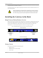
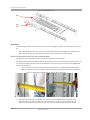
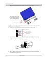
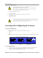
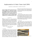
Quick Start Guide
BX4000 Series Quick Start Guide
Overview
Mellanox BX4000 series is a 1U, top-of-rack gateway that provides I/O consolidation on both InfiniBand
and Ethernet. The product supports 10/20/40Gb/S InfiniBand to 1/10Gigabit Ethernet and 2/4/8G Fibre
Channel.
The BX4000 series, a top of the rack gateway, provides LAN and SAN connection to the InfiniBand and 10
Gigabit Ethernet based networks.
The uplink and downlink ports are separated into gateway port groups. Specific uplink ports are assigned
corresponding downlink ports. Each gateway port group is assigned a color to easily associate the uplink
ports to the corresponding downlink ports of the gateway port group.
Figure 1: MTB 4010 Gateway Port Groups Distinguished by Color
B20
A10 A12 B13 B11
A1
A11 A13 B12 B10
B1
FC
EN
FC
EN
I2C
A20
Sys
Fan
PSU 1
PSU 2
IOIO
BX4010
Mellanox ®
I2C RS232 1 GigE
Gateway Port Group A – BridgeX controller 1 – White
Gateway Port Group B – BridgeX controller 1 – Orange
The Port Numbering Table shows the uplink and downlink ports by color, alpha-numeric id identifying the
IB uplink ports.
Table 1 - MTB 4010B Port Numbering
Gateway
Port Group
by Color
BridgeX
Controller
Number
Uplink
Ports
White
1
A20
A10
A11
A12 A13
A10
A11 A12
Orange
1
B20
B10
B11
B12
B10
B11
Corresponding Downlink
FC Ports
B13
Corresponding Downlink
Ethernet Ports
B12
A20 and B20 are InfiniBand ports.
Mellanox Technologies Inc.
Document Number
3054
350 Oakmead Parkway, Sunnyvale, CA 94085
Tel: 408-970-3400
Fax: 408-970-3403
www.mellanox.com
Rev 1.5
BX 4000 Sereies Quick Start Guide
Gateway Port Groups
The BridgeX gateway supports either Ethernet or InfiniBand on the uplink side, and Ethernet or FC on the
downlink side. On the downlink side all gateway port groups support a single protocol.
Figure 2: High Level Diagram
Connections to the switch
ports are arbitrary.
IB Switch
1
2
3
4
6
5
7
8
Gateway
B20
A10 A12 B13 B11
A1
A11 A13 B12 B10
B1
FC
EN
FC
EN
I2C
A20
IOIO
Sys
Fan
PSU 1
PSU 2
FC
EN
FC
EN
C1
BX4010
D1
Mellanox®
1 x vNICs
ETH3 => B11
2 x vNICs
ETH1 => A10
ETH2 => A12
ETH Cloud
ETH Cloud
ETH Cloud
Uplink Ports
There are two uplink ports, one per gateway group.These ports have CX4 4x connectors. These connectors
have support for powered cables and media adapter circuits. The BX 4010B gateways have two uplink ports.
The uplink ports are labelled alpha-numerically and also the diagrams in this manual are color coded to their
corresponding downlink ports. For IB uplinks use the single specified port for each gateway port group.
B20, A20.
Downlink Ports
There are four downlink ports per gateway port group. These ports have SFP+ connectors that support both
direct-attach copper cable and optical cables by using a SR or LR modules. The downlink ports are labelled
alpha-numerically and the diagrams in this manual are color coded to their corresponding uplink ports. The
downlink ports must all have the same protocol. When the downlink is Ethernet use ports A10-12, B10-12.
When the uplink is IB and the downlink is FC all four of the connectors can be used.
Making Connections to Other Formats
Hybrid CX4 to QSFP cables are supported on both the uplink side and the downlink side. SR and LR modules can be used on the downlink side.
CX4 connectors are supported on the uplink side.
Rev 1.5
Mellanox Technologies
2
BX 4000 Sereies Quick Start Guide
The following downlink options are supported.
•
SFP+SR for Ethernet
•
SFP+LR for Ethernet
•
FC2/4/8G
Gateway Platform Installation and Operation
Installation and initialization of the gateway platform are straightforward processes, requiring attention to
the normal mechanical, power, and thermal precautions for rack-mounted equipment.
The gateway platform requires programming and configuration to operate as a basic InfiniBand to Ethernet,
Ethernet to Ethernet, or Ethernet to Fibre Channel gateway. The gateway platform includes all of the necessary functionality to operate with external standard Subnet Management software when operating in InfiniBand to Ethernet mode.
The following sections describe the installation process and basic operation of the gateway platform. Please
first read the warnings sub-section carefully before carrying on with installation procedures.
Installation Safety Warnings
For Safety Warnings in French and German and for special regulations regarding Finland, Sweden, Denmark, and Norway see the gateway user manual.
1.
Installation Instructions
Read all installation instructions before connecting the equipment to the power
source.
2.
Over-temperature
This equipment should not be operated in an area with an ambient temperature
exceeding the maximum recommended: 45°C (113°F). Moreover, to guarantee
proper air flow, allow at least 8cm (3 inches) of clearance around the ventilation
openings.
3.
Stacking the Chassis
The chassis should not be stacked on any other equipment. If the chassis falls, it
can cause bodily injury and equipment damage.
4.
Redundant Power Supply Connection - Electrical Hazard
This product includes a blank cover over the space for the redundant power supply. Do not operate the product if the blank cover is not securely fastened or if it
is removed.
5.
During Lightning - Electrical Hazard
During periods of lightning activity, do not work on the equipment or connect or
disconnect cables.
Rev 1.5
Mellanox Technologies
3
BX 4000 Sereies Quick Start Guide
6.
Copper InfiniBand Cable Connecting/Disconnecting
Copper InfiniBand cables are heavy and not flexible, as such they should be
carefully attached to or detached from the connectors. Refer to the cable manufacturer for special warnings and instructions.
7.
Rack Mounting and Servicing
When this product is mounted or serviced in a rack, special precautions must be
taken to ensure that the system remains stable. In general you should fill the
rack with equipment starting from the bottom to the top.
8.
Equipment Installation
This equipment should be installed, replaced, or serviced only by trained and
qualified personnel.
9.
Equipment Disposal
Disposal of this equipment should be in accordance to all national laws and regulations.
10. Local and National Electrical Codes
This equipment should be installed in compliance with local and national electrical codes.
11. Hazardous Radiation Exposure
Caution – Use of controls or adjustment or performance of procedures other
than those specified herein may result in hazardous radiation exposure.
CLASS 1 LASER PRODUCT and reference to the most recent laser standards:
IEC 60 825-1:1993 + A1:1997 + A2:2001 and EN 60825-1:1994+A1:1996+
A2:2001
12. UL Approved AC Power Cords
For North American power connection, select a power supply cord that is UL
Listed and CSA Certified 3 - conductor, [18 AWG], terminated in a molded on
plug cap rated at 125 V, [15 A], with a minimum length of 1.5m [six feet] but no
longer than 4.5m.
For European connection, select a power supply cord that is internationally harmonized and marked "<HAR>", 3 - conductor, minimum 0,75 mm2 wire, rated
at 300 V, with a PVC insulated jacket. The cord must have a molded on plug cap
rated 250 V, 10 A.
Mechanical Installation
The gateway platform can be rack mounted for installation in a standard 19” rack. Power side and connector
side are arbitrary, the rack kit can be mounted so that one side is even with the vertical rack support and the
other side is recessed into the rack. For convenience we will use the terms power side of the gateway to
Rev 1.5
Mellanox Technologies
4
BX 4000 Sereies Quick Start Guide
describe the side that has the power supply modules and the fan tray, and the term connector side to describe
the side that has the CX4 and SFP+ connectors.
The installer should use a rack capable of supporting the mechanical and environmental characteristics of a
fully populated platform.
The rack mounting holes conform to the EIA-310 standard for 19-inch racks. Take precautions to guarantee proper ventilation for air intake at the power side of the chassis
and exhaust at the connector side in order to maintain good airflow at ambient temperature. Cable routing in particular should not impede the air exhaust from the chassis.
Installing the Gateway in the Rack
BridgeX Gateway Platform Hardware Overview
Figure 4 shows the power side and connector side panel views of the gateway. The figure below shows dual
hot-swap power supplies and the hot-swap fan module on the power side, and port configurations for the
gateway systems and RS232, I2C, GigE connectors and various status LEDs on the connector side.
All connectivity is via the connector side panel. All connectors can support active cables.
Figure 3: MTB4010B Gateway System Power Side and Connector Side Panels
Power Side Panel
1U
OK
OK
~AC
~AC
Fan Unit
Optional
Power Supply Unit 2
90-264 V
47-63 Hz
8A max
Power Supply Unit 1
90-264 V
47-63 Hz
8A max
Connector Side Panel
B20
A10 A12 B13 B11
A1
A11 A13 B12 B10
B1
FC
EN
FC
EN
I2C
A20
IOIO
Sys
Fan
PSU 1
PSU 2
BX4010
Mellanox ®
I2C RS232 1 GigE
Package Contents
The package should include all of the following parts:
Rev 1.5
•
BridgeX Gateway
•
Installation kit for 19” Rack mounting
•
2 Power cables
Mellanox Technologies
5
BX 4000 Sereies Quick Start Guide
•
RS232 – RJ45 to DB9 cable
•
CD
•
Quick Start Guide (this document)
Installation
The gateway platform can be rack mounted for installation in a standard 19” rack. Power side and connector
side are arbitrary, the rack kit can be mounted so that one side is even with the vertical rack support and the
other side is recessed into the rack.
Unpacking the Gateway
Before you install your new MTB4010B-PC, unpack the system and check to make sure that all the parts
have been sent, check this against the parts list. Check the parts for visible damages that may have occurred
during shipping.
Note: If anything is damaged or missing, contact your customer representative immediately.
Minimum and Maximum Rack Depth for this Gateway
This gateway can go into a 19” rack whose vertical supports are between 550mm and 800mm apart.
Tools needed
•
2 Phillips screwdrivers one small, one medium
•
ESD Strap
•
ESD mat
Parts included in the installation kit:
•
2 rails
•
1 right hand rail slide
•
1 left hand rail slide
•
16 recessed flat head screws
Note: There may be more screws in the kit than are required for installing the gateway.
Rev 1.5
•
4 pan head screws
•
2 metal washers
•
4 sets of caged nuts and bolts for the mounting plates
Mellanox Technologies
6
BX 4000 Sereies Quick Start Guide
Figure 4: Installation Kit Parts
Rail
Rail
slide
Procedure
The following procedure can be done by one person, but inserting the gateway is much easier with two people.
1.
Place the ESD mat on the Floor where you will be working and put on the ESD strap. Make sure the
ESD strap is touching your skin and that the other end is connected to a verified ground.
Decide on Placement of the Gateway within the Rack
The gateway can be installed with either side even with the rack vertical support.
The distance between the rack and the door can be as little as 4 cm on one side of the rack and as much as 18
cm on the other side of the rack. Keep in mind that there can be as many as 10 cables for the MTB4010B
onnected to the gateway.
•
Do you want the connector side recessed in the rack to allow for a larger cable bending radius?
•
Will the connector side be recessed past other equipment in the rack and will this be problematic?
Figure 5: Which Side of the Rack Do You Want the Connectors?
2.
Rev 1
Take the 2 rail slides and screw them to the gateway with the notched side up. Use eight of the
flat head screws for each rail slide. You can choose from two options for mounting the rail
slide; one option puts the end of the rail slide even with the end of the gateway and the second
Mellanox Technologies
7
BX 4000 Sereies Quick Start Guide
option recesses the gateway past the end of the rack. First catch all of the screws in the rail
slide and then tighten all of the screws together, to 3Nm or 26.5 pound inches.
This side of the gateway will
be even with the vertical rack
support. The other side of the
gateway will be deeper inside
of the rack than this side.
Notch side up
Note: The rail slides are right and left handed. if you have the wrong rail slide the holes will not align
properly with the holes in the gateway.
3.
Clip the caged nuts into the holes in the rack you will be using to connect the rails.
Figure 6: Clipping in the Caged Nuts
20
4.
The caged nuts
are separated by a
single space
Using two of the pan head screws and one washer, for each rail, install the rails to the end of
the rack. Place the rail behind the holes in the rack and screw the screws through the holes into
the rails. Do not tighten the screws just yet.
Figure 7: Connecting the Rails
5.
Rev 1
Place the bolts for the caged nuts in a convenient location, so as to be easily accessible when
you install the gateway into the rails.
Mellanox Technologies
8
BX 4000 Sereies Quick Start Guide
6.
Slide the gateway into the rails. This is easier with two people.
7.
Make sure the gateway will be level after installation.
8.
Put the gateway into place and screw the bolts into the nuts from step 5. Tighten the bolts to 9.2
Nm or 81.5 pound inches.
9.
Tighten the pan head screws, from step 4 that hold the rails, to 9.2 Nm or 81.5 pound inches.
10. Ground the gateway.
You must install an external ground to all IT components. If this gateway is installed in a grounded rack,
make sure the gateway chassis has a valid connection to the rack. If the gateway is not installed in a
grounded rack, there are two threaded screw holes marked as grounds. Connect a ground wire to one of
these grounds and connect the other end to a valid ground. Do not rely on the power connection ground.
11. Plug in the power cables.
Note: There is no On-Off switch on the gateway. The gateway will come on when the plug is plugged in.
12. Check the Status LEDs and confirm that all of the LEDs show status lights consistent with normal operation.
Warning: Any yellow status LEDs is cause for concern and must be dealt with
immediately.
13. You can start connecting all of the cables to the gateway.
Cable Installation
All cables can be inserted or removed with the unit powered on. To insert a cable, press the connector into
the port receptacle until the connector is firmly seated. The GREEN LED indicator, above of each CX4 ports
or above or below each SFP+ port, will light when the physical connection is established (that is, when the
unit is powered on and a cable is plugged into the port with the other end of the connector plugged into a
functioning port). After plugging in a cable, lock the connector using the latching mechanism particular to
the cable vendor. When a logical connection is made the yellow light will come on. When data is being
transferred the yellow light will blink.
Note: When installing SFP+ cables make sure that you hear a click when the latch engages.
Always install and remove cables by pushing or pulling the cable and connector in a straight line
with the gateway.
To remove, disengage the locks and slowly pull the connector away from the port receptacle. Both LED
indicators will turn off when the cable is unseated.
Care should be taken not to impede the air exhaust flow through the ventilation holes next to the InfiniBand
ports. Cable lengths should be used which allow for routing horizontally around to the side of the chassis
before bending upward or downward in the rack.
Cables in the bottom row should be inserted up side down in relation to the how the cables are inserted in the
top row.
Cables, especially long copper cables, can weigh a substantial amount. Make
sure that the weight of the cable is supported on its own and not hanging from
the gateway.
Rev 1
Mellanox Technologies
9
BX 4000 Sereies Quick Start Guide
Power Cycle the Gateway
If the Gateway is powered off for any reason without using the proper shut
down procedure the Flash memory may be corrupted.
If the Flash memory is corrupted the Gateway may fail to boot. Should this happen, call your Mellanox representative for assistance.
To run the gateway through a power cycle:
1.
Run: halt (if possible)
2.
Wait long enough to let the gateway halt, and verify there is no ping to it.
3.
Unplug the power cord.
4.
Plug in the power cord.
Caution: The gateway platform will automatically power on when AC power is
applied. There is no power switch. Check all boards, power supplies, and fan tray modules for proper insertion before plugging in a power cable.
Accessing and Configuring the Gateway
Access and Configuration
The gateway can be remotely accessed from a Linux terminal by three ways:
• Serial Port
•
SSH
•
Telnet
The figure below shows the possible connections to the BridgeX controllers and the Management modules.
Figure 8: I2C, RS232, and GigE Connections
I2C
I2C
IOIO
RS232
1 GigE Ethernet
Access through Serial Port
Rev 1
1.
Connect the host PC to the RS-232 port of the MTB4000 series gateway using the supplied cable.
2.
Make sure to connect to the RS-232 RJ-45 port of the switch and not to the ETH port.
Note: No remote IP connection is available at this stage.
Mellanox Technologies
10
BX 4000 Sereies Quick Start Guide
3.
Check the cable that is inside the box with your gateway. If the part number on the cable is
HAR000028 use the settings in Table 2. If the part number on the cable is HAR000034 use the
settings in Table 3.
4.
Configure a serial terminal program (for example, HyperTerminal, minicom, or Tera Term) on
your host PC with the settings described in the appropriate table.
Table 2 - Serial Terminal Program Configuration for Cable HAR000028
Parameter
Setting
Baud Rate
9600
Data bits
8
Stop bits
1
Parity
None
Flow Control
None
Table 3 - Serial Terminal Program Configuration for Cable HAR000034
5.
Parameter
Setting
Baud Rate
19200
Data bits
8
Stop bits
1
Parity
None
Flow Control
None
Login (from serial terminal program) as “admin” and use “admin” as the password.
Access through Secure Shell (SSH)
1.
Connect the CPU Ethernet port to your local 1Gigabit Ethernet network.
2.
Connect any Linux station to the Ethernet.
3.
At the prompt enter:
ssh [email protected]
4.
Enter the password.
Password: admin
Access through Telnet
1.
Connect the CPU Ethernet port to your local 1Gigabit Ethernet network.
2.
Connect any Linux station to the Ethernet.
3.
At the prompt enter:
telnet 172.22.2.2
The login appears
4.
Enter the user name “admin”.
5.
Enter the password.
Password: admin
Rev 1
Mellanox Technologies
11
BX 4000 Sereies Quick Start Guide
Change Your Password
NOTE: Managing the BX4000 cannot be done with root privileges. As such, you need to prefix all
SSH/Telnet commands with 'sudo'.
1. Enter the command
sudo passwd admin
You will be asked to put in your password in order to use the sudo command. The sudo command permissions expire periodically (usually after 5 minutes by default). See man sudo for more information.
2.
Enter your new password.
Make sure the password contains upper and lower case letters, numbers, and symbols.
Note: If your password does not contain all of the above you will get the following warning
“BAD PASSWORD: it is based on a dictionary word”.
3.
Reenter the password for confirmation.
You will be asked for your password whenever you open new connection, or when you run a sudo command.
The “sudo” command will ask for your password each time you run it. If you logout from
the current session or if it closes by timing out (10 min.), you will be asked for your password again.
Network Configuration
The only allowed user name is “admin”.
For Networking configuration:
1.
Run the following command as admin:
# sudo config_net
The following menu will appear.
1)
2)
3)
4)
2.
Configure Host Networking
Configure IP Address
Configuration for Host Networking and IP Address
Exit
Enter Your Selection:
The current HOST configuration will be displayed and you will be asked if you want to change it.
Configure Host Networking
Selection 1 under the config_net brings you to this flow. It will show the current configuration and ask if you
want to change it.
Configure Host Networking The current HOST configuration is:
NETWORKING=yes
NETWORKING_IPV6=no
GATEWAY=<IP_ADDRESS>
HOSTNAME=<hostname.domainname>
Do you want to change this configuration? [y/N]: (Default “No”)
Y – will open the following flow:
Rev 1
Mellanox Technologies
12
BX 4000 Sereies Quick Start Guide
Enable NETWORKING support [Y/n]: (Default “Yes”)
Enable NETWORKING_IPV6 support [y/N]: (Default “No”)
Enter GATEWAY an IP Address: <IP_ADDRESS>
Enter a hostname [Ex: localhost.localdomain]:<IS4.example.com>
The new HOST configuration will be displayed and you will be asked if you want to save it.
Selected configuration:
NETWORKING=yes
NETWORKING_IPV6=no
GATEWAY=<IP_ADDRESS>
HOSTNAME=<hostname.domainname>
Do you want to save the selected configuration? [Y/n]: (Default “Yes”)
Y – will save the new configuration and ask you if you want to change the IP address configuration
N – will redirect you to the main menu
If you answer ‘N’ to the first question above under “Configure Host Networking” about changing the
host configuration, it will implement the current configuration and ask you if you want to change the IP
address configuration.
Do you want to configure IP Address? [Y/n]: (Default “Yes”)
N - will redirect you to the main menu
Y – will open the configure IP address flow
Configure IP Address
Selection 2 under the config_net brings you to this flow. It will show the current configuration and ask if you
want to change it.
Configure IP Address
1) Configure by DHCP
2) Static Configuration
3) Exit
Enter Your Selection:
Selection # 1) Configure by DHCP – will show the current configuration and ask you if you want to change
it.
The current IP configuration for eth0 is:
DEVICE=eth0
BOOTPROTO=static
IPADDR=<IP_ADDRESS>
NETMASK=<NET_MASK>
HWADDR=<MAC_ADDRESS>
ONBOOT=yes
Do you want to change this configuration? [y/N]: (Default “No”)
N - will redirect you to the main menu
Y – will show the configuration for DHCP and ask you if you want to save it
The used configuration is:
DEVICE=eth0
ONBOOT=yes
HWADDR=<MAC_ADDRESS>
Rev 1
Mellanox Technologies
13
BX 4000 Sereies Quick Start Guide
BOOTPROTO=dhcp
Do you want to save the selected configuration? [Y/n]: (Default “Yes”)
Y - will save the new configuration and redirect you to the main menu
N – will redirect you to the main menu
Selection # 2) under the Configure IP Address brings you to this flow. It will show the current configuration
and ask if you want to change it.
2)Static Configuration The current IP configuration for eth0 is:
DEVICE=eth0
ONBOOT=yes
HWADDR=<MAC_ADDRESS>
BOOTPROTO=static
Do you want to change this configuration? [y/N]: (Default “No”)
N – will redirect you to the main menu
Y – will open the following flow:
Enter an IP Address:
Enter the Netmask:
Start Device On Boot? [Y/n]: (Default “Yes”)
After completing these selections the selected configuration will be displayed and you will be asked if you
want to save it.
Selected configuration:
DEVICE=eth0
BOOTPROTO=static
IPADDR=<IP_ADDRESS>
NETMASK=<NET_MASK>
HWADDR=<MAC_ADDRESS>
ONBOOT=yes
Do you want to save the selected configuration? [Y/n]: (Default “Yes”)
Y - will save the new configuration and redirect you to the main menu
N - will redirect you to the main menu
Configuration for Host Networking and IP Address
Selection 3 under the config_net brings you to this flow. It will show the current configuration and ask if you
want to change it.
Configuration for Host Networking and IP Address
This selection will open section <1> and section <2> one by one with the flows described above.
Selection 4 under the configure IP Address brings you to this flow. It will show the current configuration and
ask if you want to change it.
Exit
Exit – will exit from the program
Rev 1
Mellanox Technologies
14
BX 4000 Sereies Quick Start Guide
FabricIT BX Management
FabricIT BXM is a software based management system that can be run with either a command line interface or with a GUI interface. The GUI interface can be run through the
Web. A license is required for full use of FabricIT. The standard management module,
without a license, allows for managing the gateway using the Web interface or the command line interface and software supplied on the management chip. Make sure to register
your FabricIT license to enable all of the available commands and functions.
See the FabricIT BXM User Manual for instructions and commands available to manage
the switches, and fabric. To access this document, please contact your local Mellanox representative.
Rev 1
Mellanox Technologies
15