1
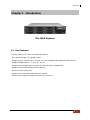
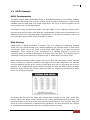
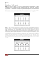
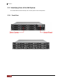
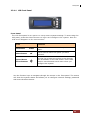
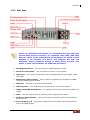
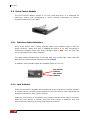
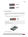
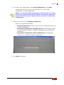
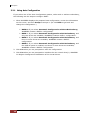
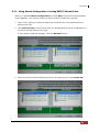
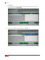
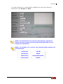
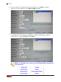
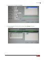
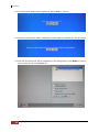
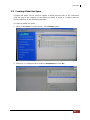
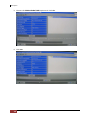
6G SAS NAS System Hardware Manual Revision 1.0 NAS System Table of Contents Preface ................................................................................................................................ 3 Before You Begin ............................................................................................................. 4 Chapter 1 Introduction ................................................................................................. 5 1.1 Key Features ............................................................................................................................................................. 5 1.2 Technical Specifications ....................................................................................................................................... 6 1.3 RAID Concepts ........................................................................................................................................................ 7 1.4 Array Definition ..................................................................................................................................................... 10 1.4.1 Drive Group ................................................................................................................................................... 10 1.4.2 Virtual Drive ................................................................................................................................................... 10 Chapter 2 Getting Started .........................................................................................11 2.1 Packaging, Shipment and Delivery ............................................................................................................... 11 2.2 Unpacking the NAS System.............................................................................................................................11 2.3 Identifying Parts of the NAS System ........................................................................................................... 12 2.3.1 Front View ......................................................................................................................................................12 2.3.1.1 2.3.2 2.4 LCD Front Panel .................................................................................................................................. 13 Rear View ........................................................................................................................................................ 15 Drive Carrier Module ..........................................................................................................................................16 2.4.1 Disk Drive Status Indicators ....................................................................................................................16 2.4.2 Lock Indicator ...............................................................................................................................................16 2.5 Installing Hard Drives .........................................................................................................................................17 2.6 Preparing the System .........................................................................................................................................18 2.7 Powering On ..........................................................................................................................................................18 Chapter 3 3.1 RAID Configuration and Management ................................................19 WebBIOS Configuration Utility .......................................................................................................................19 3.1.1 Starting the WebBIOS Configuration Utility .................................................................................... 19 3.1.2 WebBIOS CU Main Screen Options.....................................................................................................20 3.2 Configuring RAID Drive Groups and Virtual Drives ............................................................................... 22 3.2.1 Using Auto Configuration ........................................................................................................................24 3.2.2 Using Manual Configuration: Creating RAID 5 Virtual Drives .................................................. 25 3.3 Creating Global Hot Spare ............................................................................................................................... 33 3.4 Restarting the Controller ..................................................................................................................................35 2 User’s Manual NAS System Preface About this manual his manual provides information regarding the hardware features, installation and configuration of the SAS NAS System. Information contained in the manual has been reviewed for accuracy, but not for product warranty because of the various environment/OS/settings. Information and specifications will be changed without further notice. Some pictures and screenshots might be different with the actual machine. This manual uses section numbering for every topic being discussed for easy and convenient way of finding information in accordance with the user’s needs. The following icons are being used for some details and information to be considered in going through with this manual: NOTES: These are notes that contain useful information and tips that the user must give attention to in going through with the subsystem operation. IMPORTANT! These are the important information that the user must remember. WARNING! These are the warnings that the user must follow to avoid unnecessary errors and bodily injury during hardware and software operation of the subsystem. CAUTION: These are the cautions that user must be aware of to prevent damage to the equipment and its components. Copyright No part of this publication may be reproduced, stored in a retrieval system, or transmitted in any form or by any means, electronic, mechanical, photocopying, recording or otherwise, without the prior written consent. Trademarks All products and trade names used in this document are trademarks or registered trademarks of their respective owners. Changes The material in this document is for information only and is subject to change without notice. User’s Manual 3 NAS System Before You Begin efore going through with this manual, you should read and focus on the following safety guidelines. Information about the NAS system’s packaging and delivery are also included. To provide reasonable protection against any harm on the part of the user and to obtain maximum performance, user is advised to be aware of the following safety guidelines particularly in handling hardware components: Upon receiving of the product: Place the product in its proper location. To avoid unnecessary dropping out, make sure that somebody is around for immediate assistance. It should be handled with care to avoid dropping that may cause damage to the product. Always use the correct lifting procedures. Upon installing of the product: Ambient temperature is very important for the installation site. It must not exceed 30°C. Due to seasonal climate changes; regulate the installation site temperature making it not to exceed the allowed ambient temperature. Before plugging-in any power cords, cables and connectors, make sure that the power switches are turned off. Disconnect first any power connection if the power supply module is being removed from the enclosure. Outlets must be accessible to the equipment. All external connections should be made using shielded cables and as much as possible should not be performed by bare hand. Using anti-static hand gloves is recommended. In installing each component, secure all the mounting screws and locks. Make sure that all screws are fully tightened. Follow correctly all the listed procedures in this manual for reliable performance. Controller Configuration This NAS system supports single RAID controller configuration. Packaging, Shipment and Delivery Before removing the subsystem from the shipping carton, you should visually inspect the physical condition of the shipping carton. Unpack and verify that the contents of the shipping carton are complete and in good condition. Exterior damage to the shipping carton may indicate that the contents of the carton are damaged. If any damage is found, do not remove the components; contact the dealer where you purchased the subsystem for further instructions. 4 User’s Manual NAS System Chapter 1 Introduction The NAS System 1.1 Key Features - Configurable to 19" rack-mountable 2U chassis - Intel Sandy Bridge / Ivy Bridge inside - Supports up to Twelve (12) 2.5" and 3.5'' hot-swappable 6G SAS/SATA hard drives - Supports RAID levels 0, 1, 5, 6, 10, 50, 60 - Support three Gigabit Ethernet port for NAS file-sharing application - Supports Tape/DAT backup/restore (Option) - Smart-function LCD panel - Supports hot spare and automatic hot rebuild. - Allows online capacity expansion within the enclosure User’s Manual 5 NAS System 1.2 Technical Specifications Hardware Platform Intel Quad Core Xeon 3.1GHz processor System Memory:4GB DDR3 SDRAM up to 32GB Three Gigabit Ethernet ports (option for 10Gigabit Ethernet) Up to Twelve (12) 2.5" and 3.5” hot-swappable 6Gb SAS/SATA hard drives Real time drive activity and status indicators Environmental monitoring unit Two(2) 460W 80plus hot-swap power supplies with PFC Expansion PCI slot for H/W upgrade RAID Controller 800MHz RAID-On-Chip storage processor RAID level RAID 0, 1, 5, 6, 10, 50, 60 Supports 512MB DDRII cache memory Support drive hot spare and automatic hot rebuild Allow online capacity expansion within the enclosure Locally audible event notification alarm Environmental Relative humidity : 10%~85% Non-condensing Operating temp : 10oC~40oC(50oF~104oF) Power requirements AC 100V ~ 240V Full range 10A ~ 5A, 47~63Hz Physical Dimension 88(H) x 482(W) x 620(D) mm Specifications are subject to change without notice. 6 User’s Manual NAS System 1.3 RAID Concepts RAID Fundamentals The basic idea of RAID (Redundant Array of Independent Disks) is to combine multiple inexpensive disk drives into an array of disk drives to obtain performance, capacity and reliability that exceeds that of a single large drive. The array of drives appears to the host computer as a single logical drive. Five types of array architectures, RAID 1 through RAID 5, were originally defined; each provides disk fault-tolerance with different compromises in features and performance. In addition to these five redundant array architectures, it has become popular to refer to a non-redundant array of disk drives as a RAID 0 arrays. Disk Striping Fundamental to RAID technology is striping. This is a method of combining multiple drives into one logical storage unit. Striping partitions the storage space of each drive into stripes, which can be as small as one sector (512 bytes) or as large as several megabytes. These stripes are then interleaved in a rotating sequence, so that the combined space is composed alternately of stripes from each drive. The specific type of operating environment determines whether large or small stripes should be used. Most operating systems today support concurrent disk I/O operations across multiple drives. However, in order to maximize throughput for the disk subsystem, the I/O load must be balanced across all the drives so that each drive can be kept busy as much as possible. In a multiple drive system without striping, the disk I/O load is never perfectly balanced. Some drives will contain data files that are frequently accessed and some drives will rarely be accessed. By striping the drives in the array with stripes large enough so that each record falls entirely within one stripe, most records can be evenly distributed across all drives. This keeps all drives in the array busy during heavy load situations. This situation allows all drives to work concurrently on different I/O operations, and thus maximize the number of simultaneous I/O operations that can be performed by the array. User’s Manual 7 NAS System Definition of RAID Levels RAID 0 is typically defined as a group of striped disk drives without parity or data redundancy. RAID 0 arrays can be configured with large stripes for multi-user environments or small stripes for single-user systems that access long sequential records. RAID 0 arrays deliver the best data storage efficiency and performance of any array type. The disadvantage is that if one drive in a RAID 0 array fails, the entire array fails. RAID 1, also known as disk mirroring, is simply a pair of disk drives that store duplicate data but appear to the computer as a single drive. Although striping is not used within a single mirrored drive pair, multiple RAID 1 arrays can be striped together to create a single large array consisting of pairs of mirrored drives. All writes must go to both drives of a mirrored pair so that the information on the drives is kept identical. However, each individual drive can perform simultaneous, independent read operations. Mirroring thus doubles the read performance of a single non-mirrored drive and while the write performance is unchanged. RAID 1 delivers the best performance of any redundant array type. In addition, there is less performance degradation during drive failure than in RAID 5 arrays. 8 User’s Manual NAS System Under RAID 5 parity information is distributed across all the drives. Since there is no dedicated parity drive, all drives contain data and read operations can be overlapped on every drive in the array. Write operations will typically access one data drive and one parity drive. However, because different records store their parity on different drives, write operations can usually be overlapped. RAID 6 is similar to RAID 5 in that data protection is achieved by writing parity information to the physical drives in the array. With RAID 6, however, two sets of parity data are used. These two sets are different, and each set occupies a capacity equivalent to that of one of the constituent drives. The main advantage of RAID 6 is High data availability – any two drives can fail without loss of critical data. Dual-level RAID achieves a balance between the increased data availability inherent in RAID 1 and RAID 5 and the increased read performance inherent in disk striping (RAID 0). These arrays are sometimes referred to as RAID 0+1 or RAID 10 and RAID 0+5 or RAID 50. User’s Manual 9 NAS System In summary: RAID 0 is the fastest and most efficient array type but offers no fault-tolerance. RAID 0 requires a minimum of one drive. RAID 1 is the best choice for performance-critical, fault-tolerant environments. RAID 1 is the only choice for fault-tolerance if no more than two drives are used. RAID 5 combines efficient, fault-tolerant data storage with good performance characteristics. However, write performance and performance during drive failure is slower than with RAID 1. Rebuild operations also require more time than with RAID 1 because parity information is also reconstructed. At least three drives are required for RAID 5 arrays. RAID 6 is essentially an extension of RAID level 5 which allows for additional fault tolerance by using a second independent distributed parity scheme (two-dimensional parity). Data is striped on a block level across a set of drives, just like in RAID 5, and a second set of parity is calculated and written across all the drives; RAID 6 provides for an extremely high data fault tolerance and can sustain multiple simultaneous drive failures. It is a perfect solution for mission critical applications. 1.4 Array Definition 1.4.1 Drive Group A Drive Group is a group of physical drives attached to the RAID controller, and where one or more Virtual Drives (VD) can be created. All Virtual Drives in the Drive Group use all of the physical drives in the Drive Group. It is not possible to have multiple Disk Groups on the same physical disks. If physical disks of different capacity are grouped together in a Drive Group, then the capacity of the smallest disk will become the effective capacity of all the disks in the Drive Group. 1.4.2 Virtual Drive A Virtual Drive is seen by the operating system as a single drive or logical device. A Virtual Drive is a storage unit created by the RAID controller from one or more physical drives. If there is an existing Drive Group and there is available Free Space, then a new Virtual Drive can still be created. Depending on the RAID level used, the Virtual Drive may retain redundant data in case of a drive failure. 10 User’s Manual NAS System Chapter 2 Getting Started 2.1 Packaging, Shipment and Delivery Before removing the subsystem from the shipping carton, you should visually inspect the physical condition of the shipping carton. Unpack and verify that the contents of the shipping carton are complete and in good condition. Exterior damage to the shipping carton may indicate that the contents of the carton are damaged. If any damage is found, do not remove the components; contact the dealer where you purchased the subsystem for further instructions. 2.2 Unpacking the NAS System The package contains the following items: NAS System Unit Two (2) power cords Three (3) Ethernet LAN cables One (1) external serial cable One (1) RS232 null modem cable (phone jack to DB9) One (1) USB-to-PS/2 converter cable Installation Reference Guide Spare screws, etc. If any of these items are missing or damaged, please contact your dealer or sales representative for assistance. User’s Manual 11 NAS System 2.3 Identifying Parts of the NAS System The illustrations below identify the various parts of the subsystem. 2.3.1 Front View 12 User’s Manual NAS System 2.3.1.1 LCD Front Panel Front Panel The LCD front panel is an option to setup some system settings. To start using the LCD panel, press the Select button to login and configure the system. See the LCD menu diagram in the next section. Parts Exit button Function EXIT Press this button to return to the previous menu. Select button This is used to enter the option you have selected. Up and Down Arrow buttons Use the Up or Down arrow keys to go through the information on the LCD screen. This is also used to move between each menu when you configure the system. Use the function keys to navigate through the menus in the front panel. The menus will show the system status and allows you to configure network settings, password and mute the alarm buzzer. User’s Manual 13 NAS System Menu Diagram MODEL xxx.xxx.xxx.xxx VERSION 3.x.xx CHANGE PASSWORD NEW PASSWORD 00000000 SUBMIT PASSWORD SETTING(YES/NO) BEEPER SETTING SETTING MUTE / ALARM SUBMIT BEEPER SETTING(YES/NO) CPU NORMAL FAN NORMAL DISK NORMAL POWER NORMAL TEMP NORMAL RAID NORMAL DISK INFORMATION DISK_1 *O* TEMP 35C : DISK_12 *O* TEMP 35C RAID INFORMATION ARRAY NAME RAID LEVEL NETWORK INFORMATION ETHO IP xxx.xxx.xxx.xxx ETH1 IP xxx.xxx.xxx.xxx 14 User’s Manual SIZE: xxxxGB NORMAL/REBUILD/INIT ETH0 NETMASK 255.255.255.0 SUBMIT IP SETTING(YES/NO) ETH1 NETMASK 255.255.255.0 SUBMIT IP SETTING(YES/NO) NAS System 2.3.2 Rear View NOTE: For maximum performance, we recommend that you select the second PCIe bus(x8 connector) for installing other HBA (10G LAN, SAS, FC). Refer to the motherboard documentation to obtain a block diagram of all available PCI buses. This diagram will help you determine which connectors belong to which buses. Contact your dealer or sales representative for additional assistance. 1. SAS Expansion Port – For connecting to SAS Expansion Chassis. 2. Power On/Off Switch – Use this switch to power on the system. 3. LAN Ports – The system comes with three 1Gigabit Ethernet ports LAN0, LAN1 and LAN2. 4. RS232 Port (Phone-Jack) – This is used for upgrading the firmware of JBOD Controller SAS Expander board. 5. VGA Port – Use this to connect a VGA monitor. 6. USB 2.0 ports – Four USB ports are located at the rear of the system. 7. COM1 and COM2 Serial Ports – The system has one two serial ports COM1 and COM2. 8. Mute – Use the mute button to stop the power supply buzzer alarm. 9. AC Power Input Socket – Use this to plug in the power cable connected from power source. 10. Power Supply A, B – Two power supplies PSU-A and PSU-B are located at the rear of the NAS system. User’s Manual 15 NAS System 2.4 Drive Carrier Module The Drive Carrier Module houses a 3.5 inch hard disk drive. It is designed for maximum airflow and incorporates a carrier locking mechanism to prevent unauthorized access to the HDD. 2.4.1 Disk Drive Status Indicators Every Drive Carrier has 2 status indicator lights. One indicator light is used for Power On/Error. When this light is GREEN the power is on and everything is functioning normally. When the Power On/Error light is RED, then an error has occur that requires the user’s attention. The other status indicator light is the hard disk drive access light. When the hard disk drive is being accessed, this light will flash BLUE. In addition, both indicator lights are viewable within a 170° arc. Disk Activity Indicator Disk Status Indicator 2.4.2 Lock Indicator Every Drive Carrier is lockable and is fitted with a lock indicator to indicate whether or not the carrier is locked into the chassis or not. Each carrier is also fitted with an ergonomic handle for easy carrier removal. When the Lock Groove is horizontal, this indicates that the Drive Carrier is locked. When the Lock Groove is vertical, then the Drive Carrier is unlocked. Lock and unlock the Drive Carriers by using a flat-head screw driver. 16 User’s Manual NAS System Drive Carrier is Unlocked Drive Carrier is locked 2.5 Installing Hard Drives This section describes the physical locations of the hard drives supported by the NAS system and give instructions on installing a hard drive. The system supports hot-swapping allowing you to install or replace a hard drive while the NAS system is running. a. To remove a drive tray, make sure it is in unlocked position. Then press the carrier open button. The Drive Carrier handle will flip open. Carrier Open Button c. Pull out an empty disk tray. Pull the handle outwards to remove the carrier from the enclosure. d. Place the hard drive in the disk tray. Make sure the holes of the disk tray align with the holes of the hard drive. e. Install the mounting screws on the bottom part to secure the drive in the disk tray. f. Slide the tray into a slot. g. Close the handle until you hear the latch click into place. User’s Manual 17 NAS System 2.6 Preparing the System 1. Attach network cable to Ethernet port LAN0. Connect the other end to your network switch. You may also connect the other Ethernet LAN port if needed. 2. Connect monitor to the VGA port. 3. Connect PS/2 keyboard and mouse to the USB-to-PS/2 converter cable, and then connect the USB connector to the USB port on the NAS. 2.7 Powering On 1. Plug in the two power cords into the AC Power Input Socket of PSU located at the rear of the NAS system. NOTE: The NAS system is equipped with redundant, full range power supplies with PFC (power factor correction). The system will automatically select voltage. 2. Open the protective cover of the Toggle Switch. And press the toggle switch to redundant power supply mode. 3. Press the Power On/Off Switch to power on the NAS. 4. The Power LED on the front Panel will turn green. 5. Follow the steps in the next chapter to configure a RAID. 6. Follow the steps in the succeeding chapters to configure the NAS system. 18 User’s Manual NAS System Chapter 3 RAID Configuration and Management Before using the NAS system, a RAID configuration must be created. At least one virtual drive is required to be used in the NAS. You may create more than one Virtual Drive if needed. 3.1 WebBIOS Configuration Utility The WebBIOS Configuration Utility (CU) enables you to create and manage RAID configurations on LSI SAS controllers. The WebBIOS CU resides in the SAS controller BIOS and operates independently of the operating system. NOTE: For additional information about the LSI MegaRAID 92604i RAID Configuration and Management, please visit LSI web site: http://www.lsi.com/DistributionSystem/AssetDocument/files/d ocs/techdocs/storage_stand_prod/sas/mr_sas_sw_ug.pdf 3.1.1 Starting the WebBIOS Configuration Utility Perform the following steps to enter the WebBIOS Configuration Utility when you boot the system. 1. When the host computer is booting, hold down the <Ctrl> key and press the <H> key when the following text appears on the screen: LSI MegaRAID SAS-MFI BIOS Version x.xx.xx Copyright© LSI Corporation Press <Ctrl><H> for WebBIOS CU The Adapter Selection screen appears. 2. Select the SAS MegaRAID Adapter, if not selected. 3. Click Start to continue. The main WebBIOS CU screen appears. User’s Manual 19 NAS System 3.1.2 WebBIOS CU Main Screen Options The figure below shows the screen when you start the WebBIOS CU and select an adapter. In the lower right panel, the logical view part of the screen displays all of the virtual drives that are configured on this controller. In the upper right panel, the physical view part of the screen displays the drives that are connected to the controller. To toggle between the physical view and logical view of the storage devices connected to the controller, click Physical View or Logical View in the menu on the left. When the physical view screen is displayed, the lower right panel displays the drive groups that are configured on this controller. For drives in an enclosure, the screen displays the drive information in the following format: (Connector): position: slot. The connector information identifies where the chain of enclosures is connected to the RAID controller. The position number identifies the position of the enclosure in the daisy chain. Directly-attached drives displays in the following format: Slot. 20 User’s Manual NAS System The toolbar at the top of the WebBIOS CU has the following buttons: Table 3.1.2 Icon WebBIOS CU Toolbar Icons Description Click this icon to return to the main screen from any other WebBIOS CU screen. Click this icon to return to the previous screen that you were viewing. Click this icon to exit the WebBIOS CU program. Click this icon to display the Adapter Selection screen. If the computer system has multiple controllers, you use this screen to view the devices connected to a different controller. Click this icon to turn off the sound on the onboard controller alarm. Click this icon to display information about the WebBIOS CU version, browser version, and HTML interface engine. The WebBIOS CU Main Screen contains the following options: Controller Selection: Select this to view the Adapter Selection screen, where you can select a different SAS controller. You can then view information about the controller and the devices connected to it, or create a new configuration on the controller. Controller Properties: Select this to view the properties of the currently selected SAS controller. Scan Devices: Select this to have the WebBIOS CU re-scan the physical and virtual drives for any changes in the drive status or the physical configuration. The WebBIOS CU displays the results of the scan in the physical and virtual drive descriptions. Virtual Drives: Select this to view the Virtual Disks screen, where you can change and view virtual drive properties, delete virtual drives, initialize drives, and perform other tasks. Drives: Select this to view the Drives screen, where you can view drive properties, create hot spares, and perform other tasks. Configuration Wizard: Select this to start the Configuration Wizard and create a new storage configuration, clear a configuration, or add a configuration. Physical View/Logical View: Select this to toggle between the Physical View and Logical View screens. Events: Select this to view system events in the Event Information screen. Exit: Select this to exit the WebBIOS CU and continue with system boot User’s Manual 21 NAS System 3.2 Configuring RAID Drive Groups and Virtual Drives NOTE: This section describes the steps to create two RAID Level 5 Virtual Drives to be used in the NAS system. For additional information about the LSI MegaRAID 9260-4i RAID Configuration and Management, please visit the LSI web site: http://www.lsi.com/DistributionSystem/AssetDocument/files/d ocs/techdocs/storage_stand_prod/sas/mr_sas_sw_ug.pdf To create a RAID configuration: 1. Click Configuration Wizard on the WebBIOS main screen. The first Configuration Wizard screen is displayed. 2. Select a configuration option. WARNING: If you choose the first or second option, all existing data in the configuration will be deleted. Make a backup of any data that you want to keep before you choose an option. 22 Clear Configuration: Clears the existing configuration. New Configuration: Clears the existing configuration and lets you create a new configuration. Add Configuration: Retains the existing storage configuration and adds new drives to it (this does not cause any data loss). User’s Manual NAS System 3. To create a new configuration, select New Configuration. Click Next. A dialog box will warn that you will lose data if you select Clear Configuration or New Configuration. NOTE: You only select New Configuration the first time you create the drive group and virtual drives. When you add more drives and create new drive groups or virtual drives, you need to select Add Configuration. 4. On the next screen, select Manual Configuration. Types of Configuration Methods: Manual Configuration: Allows you to control all attributes of the new storage configuration. Automatic Configuration with Redundancy: Automatically creates an optimal RAID 1, RAID 5, or RAID 6 configuration, providing data redundancy. Automatic Configuration without Redundancy: Automatically creates a non-redundant RAID 0 configuration. 5. Click Next to continue. User’s Manual 23 NAS System 3.2.1 Using Auto Configuration If you select one of the Auto Configuration options, either with or without redundancy, the following are the steps to configure RAID: 1. When WebBIOS displays the proposed new configuration, review the information on the screen, and click Accept to accept it. (Or click Back to go back and change the configuration.) RAID 0: If you select Automatic Configuration without Redundancy, WebBIOS creates a RAID 0 configuration. RAID 1: If you select Automatic Configuration with Redundancy, and only two drives are available, WebBIOS creates a RAID 1 configuration. RAID 5: If you select Automatic Configuration with Redundancy, and three or more drives are available, WebBIOS creates a RAID 5 configuration. RAID 6: If you select Automatic Configuration with Redundancy, and the RAID 6 option is enabled, and three or more drives are available, WebBIOS creates a RAID 6 configuration. 2. Click Yes when you are prompted to save the configuration. 3. Click Yes when you are prompted to initialize the new virtual drive(s). WebBIOS CU begins a background initialization of the virtual drives. 24 User’s Manual NAS System 3.2.2 Using Manual Configuration: Creating RAID 5 Virtual Drives When you select Custom Configuration and click Next, the Drive Group Definition screen appears. You use this screen to select drives to create drive groups. 1. Hold <Ctrl> while you select at least three ready drives in the Physical Drives panel on the left. 2. Click Add to Array to move the drives to a proposed drive group configuration in the Drive Groups panel on the right. If you need to undo the changes, click the Reclaim button. 3. When you have finished selecting drives for the drive group, click Accept DG. User’s Manual 25 NAS System 4. Click Next. 5. The Span Definition screen appears. Drive Group 0 is shown in the Array With Free Space list. Click Add to SPAN. 6. Drive Group 0 is listed in the Span panel. Click Next. 26 User’s Manual NAS System 7. The Virtual Drive Definition screen appears. You use this screen to select the RAID level, stripe size, read policy and other attributes for the new virtual drives. Virtual Drive Parameters and Descriptions Parameter Description RAID Level The drop-down menu lists the possible RAID levels for the virtual drive. Stripe Size The stripe size specifies the length of the data segments that the RAID controller writes across multiple drives, not including parity drives. For example, consider a stripe that contains 64 KB of drive space and has 16 KB of data residing on each drive in the stripe. In this case, the stripe size is 64 KB and the strip size is 16 KB. You can set the stripe size to 8, 16, 32, 64, 128, 256, 512, and 1024 Kbytes. A larger stripe size produces higher read performance. If your computer regularly performs random read requests, choose a smaller stripe size. The default is 64 Kbytes. Access Policy Select the type of data access that is allowed for this virtual drive: Read Policy RW: Allow read/write access. This is the default. Read Only: Allow read-only access. Blocked: Do not allow access. Specify the read policy for this virtual drive: Normal: This disables the read ahead capability. This is the default. Ahead: This enables read ahead capability, which allows the controller to read sequentially ahead of requested data and to store the additional data in cache memory, anticipating that the data will be needed soon. This speeds up reads for sequential data, but there is little improvement when accessing random data. Adaptive: When Adaptive read ahead is selected, the controller begins using read ahead if the two most recent drive accesses occurred in sequential sectors. If the read requests are random, the controller reverts to Normal (no read ahead). Write Policy Specify the write policy for this virtual drive: Always Write Back: In Writeback mode the controller sends a data transfer completion signal to the host when the controller cache has received all of the data in a transaction. This setting is recommended in Standard mode. Write Through: In Writethrough mode the controller sends a data transfer completion signal to the host when the drive subsystem has received all of the data in a transaction. This is the default. User’s Manual 27 NAS System Write Back with BBU: Select this mode if you want the controller to use Writeback mode but the controller has no BBU or the BBU is bad. If you do not choose this option, the controller firmware automatically switches to Writethrough mode if it detects a bad or missing BBU. Caution: LSI allows Writeback mode to be used with or without a battery. LSI recommends that you use either a battery to protect the controller cache, or an uninterruptible power supply (UPS) to protect the entire system. If you do not use a battery or a UPS, and there is a power failure, you risk losing the data in the controller cache. IO Policy The IO Policy applies to reads on a specific virtual drive. It does not affect the read ahead cache. Direct: In Direct I/O mode, reads are not buffered in cache memory. Data is transferred to the cache and the host concurrently. If the same data block is read again, it comes from cache memory. This is the default. Cached: In Cached I/O mode, all reads are buffered in cache memory. Drive Cache Specify the drive cache policy: Enable: Enable the drive cache. Disable: Disable the drive cache. This is the default. Unchanged: Leave the current drive cache policy unchanged. Disable BGI Specify the background initialization status: No: Leave background initialization enabled. This means that a new configuration can be initialized in the background while you use WebBIOS to do other configuration tasks. This is the default. Yes: Select Yes if you do not want to allow background initializations for configurations on this controller. Select Size 28 User’s Manual Specify the size of the virtual drive in megabytes. Normally, this would be the full size for RAID 5 shown in the Configuration panel on the right. You may specify a smaller size if you want to create other virtual drives on the same drive group. NAS System To create Virtual Drive 0, select RAID 5 as RAID Level, and enter the size in Select Size. Click Accept then Next. NOTE: The Virtual Drive can use all of the capacity of the Drive Group. You may create several Virtual Drives depending on your usage and requirement. NOTE: For ProNAS 1.3.x version, the following RAID settings are recommended: Stripe Size 128 KB Read Policy Ahead Write Policy Always Write Back Drive Cache Enable User’s Manual 29 NAS System 8. VD 0 is created. To create the second Virtual Drive, click Back. The Span Definition will be displayed. Click Add to SPAN and Yes. 9. The Virtual Disk Definition screen appears. To create Virtual Drive 1, select RAID 5 as RAID Level. The remaining capacity of the Drive Group will be used by Virtual Drive 1. Select Accept and click Next. NOTE: For ProNAS 1.3.x version, the following RAID settings are recommended: 30 User’s Manual Stripe Size 128 KB Read Policy Ahead Write Policy Always Write Back Drive Cache Enable NAS System 10. Virtual Drive 1 is created. Click Next. 11. The Configuration Preview screen is shown. Click Accept to save the configuration. User’s Manual 31 NAS System 12. A Confirmation Page will be displayed. Select Yes to confirm. 13. Another Confirmation Page is displayed. Select Yes to initialize the Virtual Drives. 14. The two Virtual Drives will be initialized in the background. Click Home to return to the main screen of WebBIOS CU. 32 User’s Manual NAS System 3.3 Creating Global Hot Spare A global hot spare can be used to replace a failed physical disk in any redundant array as long as the capacity of the global hot spare is equal to or larger than the coerced capacity of the failed physical disk. To create a global hot spare: 1. While in WebBIOS CU main screen, select Drives option. 2. Select an un-configured drive and tick Properties the click Go. User’s Manual 33 NAS System 3. Choose the Make Global HSP option and click Go. 4. Click Go. 34 User’s Manual NAS System 5. The global hot spare drive is created. 3.4 Restarting the Controller 1. Verify the status of Virtual Drives. User’s Manual 35 NAS System 2. Click Exit. 3. A confirmation screen will be displayed. Select Yes. 4. A message “Please Reboot your system.” Will be displayed. Reboot your system by pressing CTRL+ALT+DEL keys. 5. The system will reboot. 6. The NAS system will be started. Please refer to Part 2 for the proNAS system configuration. 36 User’s Manual