1
Medium Voltage
SMC Flex™
Motor Controller
Bulletins 1503E, 1560E
and 1562E
User Manual
Important User Information
Read this document and the documents listed in the Additional Resources section about installation, configuration, and
operation of this equipment before you install, configure, operate, or maintain this product. Users are required to
familiarize themselves with installation and wiring instructions in addition to requirements of all applicable codes, laws,
and standards.
Activities including installation, adjustments, putting into service, use, assembly, disassembly, and maintenance are required
to be carried out by suitably trained personnel in accordance with applicable code of practice.
If this equipment is used in a manner not specified by the manufacturer, the protection provided by the equipment may be
impaired.
In no event will Rockwell Automation, Inc. be responsible or liable for indirect or consequential damages resulting from the
use or application of this equipment.
The examples and diagrams in this manual are included solely for illustrative purposes. Because of the many variables and
requirements associated with any particular installation, Rockwell Automation, Inc. cannot assume responsibility or
liability for actual use based on the examples and diagrams.
No patent liability is assumed by Rockwell Automation, Inc. with respect to use of information, circuits, equipment, or
software described in this manual.
Reproduction of the contents of this manual, in whole or in part, without written permission of Rockwell Automation,
Inc., is prohibited.
Throughout this manual, when necessary, we use notes to make you aware of safety considerations.
WARNING: Identifies information about practices or circumstances that can cause an explosion in a hazardous environment,
which may lead to personal injury or death, property damage, or economic loss.
ATTENTION: Identifies information about practices or circumstances that can lead to personal injury or death, property
damage, or economic loss. Attentions help you identify a hazard, avoid a hazard, and recognize the consequence.
IMPORTANT
Identifies information that is critical for successful application and understanding of the product.
Labels may also be on or inside the equipment to provide specific precautions.
SHOCK HAZARD: Labels may be on or inside the equipment, for example, a drive or motor, to alert people that dangerous
voltage may be present.
BURN HAZARD: Labels may be on or inside the equipment, for example, a drive or motor, to alert people that surfaces may
reach dangerous temperatures.
ARC FLASH HAZARD: Labels may be on or inside the equipment, for example, a motor control center, to alert people to
potential Arc Flash. Arc Flash will cause severe injury or death. Wear proper Personal Protective Equipment (PPE). Follow ALL
Regulatory requirements for safe work practices and for Personal Protective Equipment (PPE).
Allen-Bradley, Rockwell Software, Rockwell Automation, and TechConnect are trademarks of Rockwell Automation, Inc.
Trademarks not belonging to Rockwell Automation are property of their respective companies.
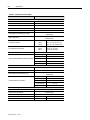
Table of Contents
Page
Preface
Service Procedure ............................................................................ P-1
Product Overview
Chapter 1
Manual Objectives ............................................................................ 1-1
Documentation .................................................................................. 1-1
Description........................................................................................ 1-1
1503E – OEM Controller ........................................................... 1-1
1560E – Retrofit Controller ....................................................... 1-2
1562E – Combination Controller ............................................... 1-2
SMC-Flex Control Module ......................................................... 1-2
Starting Modes .................................................................................. 1-3
Soft Start .................................................................................... 1-3
Selectable Kickstart.................................................................... 1-4
Current Limit Start ..................................................................... 1-4
Dual Ramp Start ......................................................................... 1-5
Full Voltage Start ....................................................................... 1-5
Preset Slow Speed ....................................................................... 1-6
Linear Speed Acceleration and Deceleration .............................. 1-7
Soft Stop ...................................................................................... 1-8
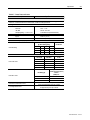
Protection and Diagnostics ............................................................... 1-9
Overload ..................................................................................... 1-9
Underload .................................................................................. 1-11
Undervoltage ............................................................................. 1-11
Overvoltage ............................................................................... 1-11
Unbalance .................................................................................. 1-12
Stall Protection and Jam Detection ........................................... 1-12
Ground Fault ............................................................................. 1-13
Thermistor/PTC Protection ....................................................... 1-14
Open Gate ................................................................................ 1-16
Line Faults ................................................................................ 1-16
Excessive Starts/Hour .............................................................. 1-17
Overtemperature ....................................................................... 1-17
Metering.......................................................................................... 1-17
Communication ............................................................................... 1-18
Programming .................................................................................. 1-18
Status Indication ............................................................................. 1-19
Control Options .............................................................................. 1-19
Pump Control Option ............................................................... 1-19
Application Considerations .................................................. 1-20
Braking Control Option ............................................................. 1-21
Hardware Description ..................................................................... 1-22
Power Module .......................................................................... 1-22
Self-Powered Silicon-Controlled Rectifier Gate Driver Board .... 1-22
Interface Board ......................................................................... 1-23
1560E-UM050B-EN-P - June 2013
ii
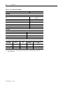
Table of Contents – MV Dialog Plus Medium Voltage Controller User Manual
Product Overview (cont.)
Chapter 1
Page
Typical MV SMC-Flex Power System Diagrams
Bulletin 1562E (Without Stop Control) .................................... 1-24
Bulletin 1562E (With Stop Control) .......................................... 1-25
Bulletin 1562E (Without Stop Control) ..................................... 1-26
Bulletin 1562E (With Stop Control) .......................................... 1-27
Functional Descriptions .................................................................. 1-28
Bulletin 1562E • Basic Control – Controlled Start Only ......... 1-28
Bulletin 1562E • Basic Control – With Controlled Stop ........... 1-29
Bulletin 1562E • DPI Control – Controlled Start Only ............. 1-29
Bulletin 1560E • Basic Control – Controlled Start Only ......... 1-30
Bulletin 1560E • Basic Control – With Controlled Stop ........... 1-30
Bulletin 1560E • DPI Control – Controlled Start Only ............. 1-30
Schematics:
Bul. 1562E IntelliVAC Control Circuit (Without Stop Control) ... 1-31
Bul. 1562E IntelliVAC Control Circuit (With Stop Control) ........ 1-32
Bul. 1562E IntelliVAC Control Circuit (With DeviceNet) ........... 1-33
Bul. 1560E IntelliVAC Control Circuit (Without Stop Control) ... 1-34
Bul. 1560E IntelliVAC Control Circuit (With Stop Control) ........ 1-35
Bul. 1560E IntelliVAC Control Circuit (With DeviceNet) .......... 1-36
Installation
Chapter 2
Receiving .......................................................................................... 2-1
Safety and Codes .............................................................................. 2-1
Unpacking and Inspection ................................................................ 2-1
General Precautions .......................................................................... 2-2
Transportation and Handling ............................................................ 2-2
Installation Site ................................................................................. 2-3
Mounting ..................................................................................... 2-3
Grounding Practices .................................................................... 2-4
Recommended Torque Values ........................................................... 2-4
Power Connections ........................................................................... 2-5
Bulletin 1562E ............................................................................ 2-5
Bulletin 1560E ............................................................................ 2-8
Bulletin 1503E .......................................................................... 2-11
Power Wiring .................................................................................. 2-12
Interlocking ..................................................................................... 2-12
Installation ...................................................................................... 2-13
Physical Location ...................................................................... 2-13
Fan ............................................................................................. 2-13
Ground Bus Bar......................................................................... 2-13
Power and Control Wiring ........................................................ 2-13
Control Cables ........................................................................... 2-13
Fibre-Optic Cables .................................................................... 2-13
Power Factor Correction Capacitors ......................................... 2-14
1560E-UM050B-EN-P - June 2013
Table of Contents – MV Dialog Plus Medium Voltage Controller User Manual
Installation (cont.)
Chapter 2
iii
Page
Surge Arrestor Protection Devices ................................................. 2-16
Motor Overload Protection ............................................................. 2-17
EMC Compliance ............................................................................ 2-18
Control Power .................................................................................. 2-19
Control Terminal Designations ...................................................... 2-20
Commissioning Procedure
Chapter 3
Preliminary Set-Up ........................................................................... 3-1
System Characteristics ...................................................................... 3-2
Preliminary Check ............................................................................ 3-3
Programming .................................................................................... 3-3
Hi-Pot and Megger Test.................................................................... 3-4
Typical MV SMC-Flex Power System Diagram ............................... 3-5
Connection and Test Information for Interface Board ...................... 3-6
Power Supply Tests .......................................................................... 3-7
Control Function Tests ................................................................... 3-10
Resistance Checks .......................................................................... 3-11
Voltage Sensing Module ................................................................. 3-11
Start-Up .......................................................................................... 3-12
Programming
Chapter 4
Overview........................................................................................... 4-1
Keypad Description .......................................................................... 4-1
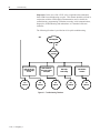
Programming Menu .......................................................................... 4-1
Menu Structure Hierarchy ................................................................. 4-2
Parameter Linear List ........................................................................ 4-4
Password ........................................................................................... 4-5
Parameter Management ................................................................... 4-6
Parameter Modification .................................................................... 4-8
Soft Start ........................................................................................... 4-9
Current Limit Start ............................................................................ 4-9
Dual Ramp Start ............................................................................. 4-10
Full Voltage Start ........................................................................... 4-11
Linear Speed .................................................................................... 4-11
Basic Setup ..................................................................................... 4-11
Motor Protection .............................................................................. 4-13
Example Settings ............................................................................ 4-13
Motor Information ........................................................................... 4-15
1560E-UM050B-EN-P - June 2013
iv
Table of Contents – MV Dialog Plus Medium Voltage Controller User Manual
Metering
Chapter 5
Page
Overview........................................................................................... 5-1
Motor Data Entry .............................................................................. 5-1
Options
Chapter 6
Overview........................................................................................... 6-1
Human Interface Module .................................................................. 6-1
Programming Parameters ................................................................... 6-3
Control Wiring ................................................................................... 6-5
Diagnostics
Chapter 7
Overview........................................................................................... 7-1
Fault Display...................................................................................... 7-1
Clear Fault ......................................................................................... 7-2
Fault Buffer........................................................................................ 7-2
Fault Contact...................................................................................... 7-3
Fault Definitions ................................................................................ 7-4
Communications
Chapter 8
Overview............................................................................................ 8-1
Communication Ports ........................................................................ 8-1
Human Interface Module ................................................................... 8-1
Keypad Description ..................................................................... 8-2
Connecting the Human Interface Module to the Controller ........ 8-4
Control Enable ............................................................................ 8-4
Control Enable ................................................................................... 8-6
Loss of Communication and Network Faults .................................... 8-6
SMC-Flex Specific Information ........................................................ 8-6
Default Input/Output Configuration .................................................. 8-7
Variable Input/Output Configuration ................................................ 8-7
SMC-Flex Bit Identification .............................................................. 8-8
Reference/Feedback ........................................................................... 8-9
Parameter Information ....................................................................... 8-9
Scale Factors for PLC Communication ............................................. 8-9
Display Text Unit Equivalents .......................................................... 8-9
Configuring DataLinks .................................................................... 8-10
Updating Firmware .......................................................................... 8-10
1560E-UM050B-EN-P - June 2013
Table of Contents – MV Dialog Plus Medium Voltage Controller User Manual
Troubleshooting
Chapter 9
v
Page
General Notes and Warnings ............................................................ 9-1
Fault Display Explanation ................................................................ 9-3
Control Module Removal .................................................................. 9-6
Voltage Feedback Circuit Tests ......................................................... 9-7
Voltage-Sensing Board Replacement ................................................ 9-8
IGDPS Boards ................................................................................... 9-9
IGDPS Board LEDs ......................................................................... 9-10
Circuit Board Replacement.............................................................. 9-11
Power Circuit Troubleshooting ....................................................... 9-12
Thyristor (SCR) Testing............................................................ 9-12
SCR Replacement Procedure .................................................... 9-13
Snubber and Resistor Circuit Testing .............................................. 9-27
Snubber Resistor Replacement ........................................................ 9-30
Wiring Diagrams ............................................................................. 9-31
Maintenance
Chapter 10
Safety and Preventative ................................................................... 10-1
Periodic Inspection .......................................................................... 10-1
Contamination ........................................................................... 10-1
Vacuum Bottles ......................................................................... 10-2
Terminals .................................................................................. 10-2
Coils .......................................................................................... 10-2
Solid-State Devices ................................................................... 10-3
Static-Sensitive Items ................................................................ 10-3
Overload Maintenance After a Fault Condition ........................ 10-3
Final Check Out ........................................................................ 10-3
"Keep Good Maintenance Records" ......................................... 10-4
Power Components ................................................................... 10-4
Control Components – Electronic ............................................. 10-4
Fans ........................................................................................... 10-4
Interlocks ................................................................................... 10-4
Barriers ...................................................................................... 10-4
Environmental Considerations......................................................... 10-5
Hazardous Materials ................................................................. 10-5
Disposal ..................................................................................... 10-6
1560E-UM050A-EN-P – August 2004
vi
Table of Contents – MV Dialog Plus Medium Voltage Controller User Manual
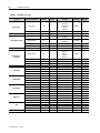
Appendix A
1560E/1562E SMC-Flex Specifications
Page
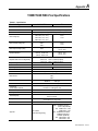
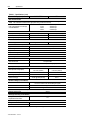
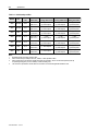
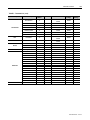
Specifications – Table A.1 ............................................................... A-1
Altitude Derating –Table A.2 ........................................................... A-3
Area Available for Cable Entry/Exit – Table A.3 ............................ A-3
Cable Quantity and Size – Table A.4 ............................................... A-4
Shipping Weights and Dimensions – Table A.5 ............................... A-5
Power Bus and Ground Bus – Table A.6 .......................................... A-6
Power Fuses and Losses – Table A.7 ............................................... A-7
Control Wire and Power Wire – Table A.8 ...................................... A-8
Appendix B
Parameter Information
Parameter List ................................................................................... B-1
Appendix C
1560E and 1562E Relay Control
Functional Description ..................................................................... C-1
Bulletin 1562E • Basic Control – Controlled Start Only .......... C-1
Bulletin 1562E • Basic Control – With Controlled Stop ............ C-2
Bulletin 1562E • DPI Control – Controlled Start Only .............. C-2
Bulletin 1560E • Basic Control – Controlled Start Only .......... C-3
Bulletin 1560E • Basic Control – With Controlled Stop ............ C-3
Bulletin 1560E • DPI Control – Controlled Start Only .............. C-4
Schematics:
Bul. 1562E Relay Control Circuit (Without Stop Control) ............ C-5
Bul. 1562E Relay Control Circuit (With Stop Control) ................. C-6
Bul. 1562E Relay Control Circuit (With DeviceNet) ................... C-7
Bul. 1560E Relay Control Circuit (Without Stop Control) ............ C-8
Bul. 1560E Relay Control Circuit (With Stop Control) ................. C-9
Bul. 1560E Relay Control Circuit (With DeviceNet) ................. C-10
Appendix D
Spare Parts
Bul. 1503E • 1000-1500V, 180/360A (6-device) ............................. D-1
Bul. 1503E, 1560E, 1562E • 2300V, 180/360A (6-device) .............. D-2
Bul. 1503E, 1560E, 1562E • 2300V, 600A (6-device) ..................... D-3
Bul. 1503E, 1560E, 1562E • 3300/4160V, 180/360A (12-device) ... D-4
Bul. 1503E, 1560E, 1562E • 3300/4160V, 600A (12-device) .......... D-5
Bul. 1503E, 1560E, 1562E • 5500/6900V, 180/360A (18-device) ... D-6
Bul. 1503E, 1560E, 1562E • 5500/6900V, 600A (18-device) .......... D-7
Accessories ....................................................................................... D-8
Appendix E
Accessories
Accessories ........................................................................................ E-1
1560E-UM050A-EN-P – August 2004
Preface
Service Procedure
For your convenience, the Rockwell Automation Global Manufacturing
Solutions (GMS), provides an efficient and convenient method of servicing
medium voltage products.
Contact your local area support office to make arrangements to have a
qualified service representative come to your facility.
A complete listing of Area Support Offices may be obtained by calling your
local Rockwell Automation Distributor or Sales Office.
For MV SMC-Flex technical support on start-up or existing installations,
contact your Rockwell Automation representative. You can also call
1-519-740-4790 for assistance Monday through Friday from 9:00 a.m.
to 5:00 p.m. (Eastern time zone).
1560E-UM050B-EN-P - June 2013
Preface
1560E-UM050B-EN-P - June 2013
Chapter
1
Product Overview
Manual Objectives
This manual is intended for use by personnel familiar with Medium Voltage and
solid-state power equipment. The manual contains material which will allow the
user to operate, maintain and troubleshoot the MV SMC-FlexTM family of
controllers. The family consists of the following Bulletin numbers: 1503E,
1560E and 1562E.
Documentation
The following Rockwell Automation publications provide pertinent
information for the MV SMC-Flex and components:
• MVB-5.0
• 1500-UM055B-EN-P
• 1502-UM050C-EN-P
• 1502-UM052B-EN-P
• 1502-UM051C-EN-P
• 1560E-SR022A-EN-P
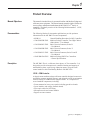
Description
General Handling Procedures for MV Controllers
Medium Voltage Controller Two-High Cabinet
(200A/400A) – User Manual
400A Vacuum Contactor, Series D
– User Manual
400A Vacuum Contactor, Series E
– User Manual
800A Vacuum Contactor, Series D and E
– User Manual
Medium Voltage SMC-Flex Controllers
– General Specifications
The MV SMC-Flex is a solid-state, three-phase, AC line controller. It is
designed to provide microprocessor-controlled starting and stopping of
standard three-phase, squirrel-cage induction motors, using the same
control module as the Allen-Bradley Bulletin 150 SMC-Flex.
1503E – OEM Controller
A chassis-mount medium voltage solid-state controller designed to mount in
an OEM or customer supplied structure, and designed to work in conjunction
with an existing or OEM/customer supplied starter. It is comprised of
several modular components, including:
•
•
•
•
•
Frame-mounted or loose power stacks including gate driver boards
Loose interface and voltage feedback boards
Fiber optic cables for SCR firing
Microprocessor based control module
Bypass vacuum contactor
%5-"%.0*UNE
1-2
Product Overview%5-"%.0*UNE%5-"%.0*UNE
Description (cont.)
1560E – Retrofit Controller
A medium voltage solid-state controller designed to work in conjunction
with an existing customer-supplied starter. It includes:
•
•
•
•
•
•
•
Tin-plated, copper, horizontal power bus (optional)
A continuous, bare copper ground bus
Power electronics
A bypass vacuum contactor
Three (3) current transformers
A low voltage control panel complete with microprocessor-based control module
Top and bottom plates to accommodate power cables.
Note: See Interlocking, page 2-8.
1562E – Combination Controller
A medium voltage solid-state controller that provides isolation and
protection for new installations. It includes:
•
•
•
•
•
•
•
•
•
•
Tin-plated, copper, horizontal power bus (optional)
A continuous, bare copper ground bus
Power electronics
A main non-load-break isolating switch and operating handle
An isolation vacuum contactor
A bypass vacuum contactor
Three (3) current limiting power fuses for NEMA Class E2 operation
Three (3) current transformers
A control power transformer (optional)
A low voltage control panel complete with microprocessor-based control
module
• Space for necessary auxiliary control and metering devices
• Top and bottom plates to accommodate power cables
• Motor overload protection (included in SMC-Flex control module)
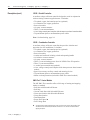
SMC-Flex™ Control Module
The MV SMC-Flex controller offers a full range of starting and stopping
modes as standard:
• Soft Start with Selectable Kickstart
• Soft Stop
• Current Limit Start with Selectable Kickstart
• Linear Acceleration with Selectable Kickstart
• Linear Deceleration
• Dual Ramp Start
• Preset Slow Speed :
• Full Voltage Start
:
%5-"%.0*UNE
This option utilizes gating patterns which result in motor and line currents that produce noise
and vibration in the motor and/or distribution transformer. This must be considered before
applying this option.
Product Overview
1-3%5-"
SMC-Flex™ Control Module (cont.)
Other features that offer further user benefit include:
• Extensive protection features
• Metering
• Communication capability
Innovative control option provides enhanced performance:
• Pump Control (Start and Stop Control modes)
These modes, features and options are further described in this chapter.
:
Starting Modes
This option utilizes gating patterns which result in motor and line currents that produce noise and vibration
in the motor and/or distribution transformer. The factory should be consulted before applying this option.
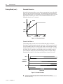
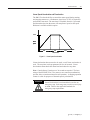
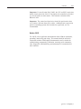
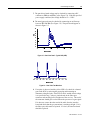
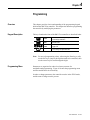
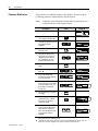
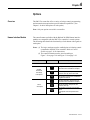
Soft Start
This mode has the most general application. The motor is given an initial
torque setting, which is user-adjustable from 0 to 90% of locked-rotor
torque. From the initial torque level, the output voltage to the motor is
steplessly increased during the acceleration ramp time. The acceleration
ramp time is user-adjustable from 0 to 30 seconds. Once the MV SMC-Flex
controller senses that the motor has reached the up-to-speed condition during
the voltage ramp operation, the output voltage automatically switches to
full voltage, and the bypass contactor is closed.
Figure 1.1– Soft Start
%5-"%.0*UNE
1-4
Product Overview
Starting Modes (cont.)
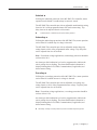
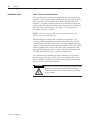
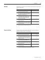
Selectable Kickstart :
Selectable kickstart provides a power boost at start-up that is user-adjustable
from 0 to 90% of locked rotor torque. The additional power helps motors
generate higher torque to overcome the resistive mechanical forces of some
applications when they are started. The selectable kickstart time is useradjustable from 0.0 to 2.0 seconds.
Kickstart
100%
Initial
Torque
Start
Run
Time (seconds)
Figure 1.2 – Selectable Kickstart
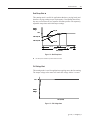
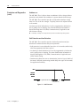
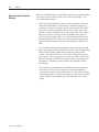
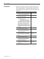
Current Limit Start
;
This starting mode provides a true current limit start that is used when
limiting the maximum starting current is necessary. The Current Limit level
is user-adjustable from 50% to 600% of the motor's full-load ampere rating,
and the current limit time is user-adjustable from 0 to 30 seconds. Once the
MV SMC-Flex™ controller senses that the motor has reached the up-tospeed condition during the current limit starting mode, the output voltage
automatically switches to full voltage and the bypass contactor is closed.
600%
Percent Full
Load Current
50%
Start
Time (seconds)
Figure 1.3 – Current Limit Start
:
;
%5-"%.0*UNE
Kickstart is also available with Current Limit Start, Dual Ramp Start and Linear Acceleration.
The Current Limit Start mode design is based on a motor with a locked-rotor current rating that is 600% of
the full-load current rating.
Product Overview
1-5
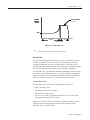
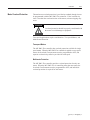
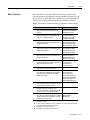
Dual Ramp Start :
This starting mode is useful for applications that have varying loads (and
therefore varying starting torque requirements). Dual Ramp Start allows
the user to select between two separate Soft Start profiles with separately
adjustable ramp times and initial torque settings.
Percent
Voltage
Ramp #2
100%
Initial Torque #2
Initial Torque #1
Ramp #1
Run #1
Start #1
Start #2
Run #2
Time (seconds)
Figure 1.4 – Dual Ramp Start
:
Dual Ramp Start is available only with the standard controller.
Full Voltage Start
This starting mode is used for applications requiring across-the-line starting.
The output voltage to the motor will reach full voltage within ¼ second.
100%
Percent
Voltage
Time (seconds)
Figure 1.5 – Full Voltage Start
%5-"%.0*UNE
1-6
Product Overview
Starting Modes (cont.)
Preset Slow Speed
This option can be used in applications that require a slow-speed jog for
general purpose positioning. Preset Slow Speed provides either 7% of
base speed (low) or 15% of base speed (high) settings in the forward
direction. Reverse can also be programmed and offers 10% of base speed
(low) and 20% of base speed (high) settings.
Forward
15% – High
7% – Low
Time (seconds)
Start
Run
10% – Low
20% – High
Reverse
Figure 1.6 – Preset Slow Speed Option
Important: Slow speed running is not intended for continuous operation due
to reduced motor cooling. The two starts per hour limitation also applies to
slow speed operation. This option employs a cycle-skipping scheme which
produces limited torque. Applications should be checked with the factory.
%5-"%.0*UNE
Product Overview
1-7
Linear Speed Acceleration and Deceleration
The SMC-Flex has the ability to control the motor speed during starting
and stopping maneuvers. A tachometer signal (0 to 5V DC) is required to
perform this start mode. The start time is selectable from 0 to 30 seconds
and determines the time the motor will ramp from 0 speed to full speed.
Kickstart is available with this option.
100%
Motor
Speed
Start
Run
Time (seconds)
Stop
Figure 1.7 – Linear Speed Acceleration
Linear deceleration does not need to be used, even if linear acceleration is
used. The stop time can be programmed for 0 to 60 seconds. Linear
deceleration cannot brake the motor/load and reduce the stop time.
Note: Consult factory if settings over 30 seconds are required. The base
rating of the MV SMC-Flex is two starts (or one start/stop combination)
per hour, thirty seconds maximum for each operation. A stopping operation
counts as a start for purposes of thermal capacity calculations.
ATTENTION
Linear Deceleration is not intended to be used as an
emergency stop. Such usage may result in severe injury
or death. Refer to the applicable standards for
emergency stop requirements.
%5-"%.0*UNE
1-8
Product Overview%5-"%.0*UNE%5-"%.0*UNE
Starting Modes (cont.)
Soft Stop
This feature can be used in applications that require an extended coast-torest time. The voltage ramp-down time is user-adjustable from 0 to 60
seconds and is adjusted independently from the starting time. The load
will stop when the output voltage drops to a point where the load torque is
greater than the developed motor torque.
Percent
Voltage
100%
Kickstart
Coast-to-rest
Soft Stop
Initial
Torque
Start
Run
Time (seconds)
Soft Stop
Figure 1.8 – Soft Stop Option
Note: Consult factory if settings over 30 seconds are required. The base
rating of the MV SMC-Flex is two starts (or one start/stop combination)
per hour, thirty seconds maximum for each operation. A stopping operation
counts as a start for purposes of thermal capacity calculations.
ATTENTION
%5-"%.0*UNE
Soft Stop is not intended to be used as an emergency
stop. Such usage may result in severe injury or death.
Refer to the applicable standards for emergency stop
requirements.
Product Overview
Protection and Diagnostics
1-9
The MV SMC-Flex™ controller is capable of providing the following
protective and diagnostic features:
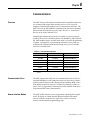
Overload
The MV SMC-Flex controller meets applicable requirements as a motor
overload protection device. Thermal memory provides added protection
and is maintained even when control power is removed. The built-in
overload algorithm controls the value stored in Parameter 12, Motor
Thermal Usage (see Chapter 4, Programming). An Overload Fault will
occur when this value reaches 100%. The parameters below provide
application flexibility and easy setup.
Parameter
Range
Overload Class
Overload Reset
Motor FLC
Service Factor
Off, 10, 15, 20, 30
Manual – Auto
1.0 – 1000.0 amps
0.01 – 1.99
Important: During slow speed operations, current waveforms exhibit
non-sinusoidal characteristics. These non-sinusoidal characteristics
inhibit the controller's current-measurement capability. To compensate
for additional motor heating that may result, the controller uses motor
thermal modeling, which increments motor thermal usage. This compensation takes place when the Preset Slow Speed option is used.
Notes:
1. The factory default setting for Overload Class, which is "OFF", disables
overload protection. An overload trip class and the motor's full-load
current rating must be programmed to enable overload protection.
2. If the MV SMC-Flex is used to control a multi-speed motor, or more
than one motor, the Overload Class parameter must be programmed
to "OFF" and separate overload relays must be supplied for each
speed/motor.
3. Automatic reset of an overload fault requires the start input to be
cycled in a 2-wire control scheme.
4. The trip rating is 117% of the programmed FLC.
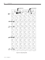
Figures 1.9 and 1.10 provide the overload trip curves for the available trip
classes.
%5-"%.0*UNE
1-10
Product Overview
Protection and Diagnostics
(cont.)
Class 15
Class 10
1.0
0.1
1
2
3
4
5
6 7 8 9 10
1000.0
100.0
10.0
1.0
1
2
Multiples of FLC
3
4
5
Approximate Trip Time (seconds)
10.0
10000.0
10000.0
Approximate Trip Time (seconds)
Approximate Trip Time (seconds)
Approximate Trip Time (seconds)
100.0
Class 30
Class 20
10000.0
1000.0
1000.0
100.0
10.0
10.0
1.0
1
2
3
4
5
6 7 8 9 10
Multiples of FLC
Approximate trip time for 3-phase balanced
condition from cold start.
Approximate trip time for 3-phase balanced
condition from hot start.
Figure 1.9 – Overload Trip Curves
100000
1000
Seconda
100
Class 10
Class 15
Class 20
Class 30
10
Auto Reset Times:
Class 10 = 90 s
Class 15 = 135 s
Class 20 = 180 s
Class 30 = 270 s
1
0
1000%
Percent Full Load Current Setting
Figure 1.10 – Restart Trip Curves after Auto Reset
%5-"%.0*UNE
100.0
1.0
6 7 8 9 10
Multiples of FLC
100%
1000.0
1
2
3
4
5
Multiples of FLC
6 7 8 9 10
Product Overview
1-11
Underload :
Utilizing the underload protection of the MV SMC-Flex controller, motor
operation can be halted if a sudden drop in current is sensed.
The MV SMC-Flex controller provides an adjustable underload trip setting
from 0 to 99% of the programmed motor full load current rating. Trip
delay time can be adjusted from 0 to 99 seconds.
: Underload protection is disabled during slow speed and braking operations.
Undervoltage ;
Utilizing the undervoltage protection of the MV SMC-Flex, motor operation
can be halted if a sudden drop in voltage is detected.
The MV SMC-Flex controller provides an adjustable undervoltage trip
setting from 0 to 99% of the programmed motor voltage. Trip delay time
can be adjusted from 0 to 99 seconds.
Note: For medium voltage applications, undervoltage protection should be
set from 80 to 99%.
An alarm (pre-fault) indication level can be programmed to indicate the
unit is getting close to faulting. The alarm modification information is
displayed through the LCD, HIM, Communication (if applicable) and
alarm contact closing.
Overvoltage ;
Utilizing the overvoltage protection of the MV SMC-Flex, motor operation
can be halted if a sudden increase in voltage is detected.
The MV SMC-Flex controller provides an adjustable overvoltage trip
setting from 0 to 199% of the programmed motor voltage. Trip delay time
can be adjusted from 0 to 99 seconds.
Note: For medium voltage applications, overvoltage protection should be
set from 100 to 115%.
An alarm (pre-fault) indication level can be programmed to indicate the
unit is getting close to faulting. The alarm modification information is
displayed through the LCD, HIM, Communication (if applicable) and
alarm contact closing.
;Undervoltage, overvoltage, and voltage unbalance protection are disabled during braking operation.
%5-"%.0*UNE
1-12
Product Overview
Protection and Diagnostics
(cont.)
Unbalance :
The MV SMC-Flex is able to detect an unbalance in line voltages. Motor
operation can be halted if the unbalance is greater than the desired range.
The MV SMC-Flex controller provides an adjustable unbalance setting
from 0 to 25% of the line voltages. Trip delay time can be adjusted from 0
to 99 seconds.
An alarm (pre-fault) indication level can be programmed to indicate the
unit is getting close to faulting. The alarm modification information is
displayed through the LCD, HIM, Communication (if applicable) and
alarm contact closing.
:Undervoltage, overvoltage, and voltage unbalance protection are disabled during braking operation.
Stall Protection and Jam Detection
The MV SMC-Flex controller provides both stall protection and jam
detection for enhanced motor and system protection.
• Stall protection is user-adjustable from 0.0 to 10.0 seconds (enabled only
after the programmed start time expires).
• An alarm (pre-fault) indication level can be programmed to indicate the
unit is getting close to faulting. The alarm modification information is
displayed through the LCD, HIM, Communication (if applicable) and
alarm contact closing.
• Jam detection allows the user to determine the jam level (up to 1000% of
the motor's full-load current rating) and the delay time (up to 99.0 seconds)
for application flexibility.
600%
Percent
Full Load
Current
Programmed Start Time
Stall
Time (seconds)
Figure 1.11 – Stall Protection
%5-"%.0*UNE
Product Overview
Percent
Full Load
Current
1-1
User Programmed
Trip Level
600%
Jam
Running
Time (seconds)
Figure 1.12 – Jam Detection :
: Jam Detection is disabled during slow speed and braking operation.
Ground Fault
In isolated or high impedance-grounded systems, core-balanced current
sensors are typically used to detect low level ground faults caused by
insulation breakdowns or entry of foreign objects. Detection of such
ground faults can be used to interrupt the system to prevent further damage,
or to alert the appropriate personnel to perform timely maintenance.
The MV SMC-Flex’s ground fault detection capabilities consist of using a
core balance current transformer for 1 to 5A core-balanced ground fault
protection with the option of enabling Ground Fault Trip, Ground Fault
Alarm, or both (a core balance CT is provided with 1562E units).
Ground Fault Trip
The MV SMC-Flex will trip with a ground fault indication if:
• No trip currently exists
• Ground fault protection is enabled
• GF Inhibit Time has expired
• GF Current is equal to or greater than the GF Trip Level for a time
period greater than the GF Trip Delay
Parameter 75, Gnd Flt Inh Time, allows the installer to inhibit a ground
fault trip from occurring during the motor starting sequence and is
adjustable from 0 to 250 seconds.
%5-"%.0*UNE
1-14
Product Overview
Protection and Diagnostics
(cont.)
Ground Fault Trip (cont.)
Parameter 74, Gnd Flt Delay, allows the installer to define the time period
a ground fault condition must be present before a trip occurs. It is
adjustable from 0.1 to 25 seconds.
Parameter 73, Gnd Flt Level, allows the installer to define the ground
fault current at which the MV SMC-Flex will trip. It is adjustable from
1.0 to 5.0 A.
Important: The ground fault inhibit timer starts after the maximum phase
of load current transitions from 0 A to 30% of the device’s minimum FLA
Setting or the GF Current is greater than or equal to 0.5 A. The MV
SMC-Flex does not begin monitoring for a ground fault condition until the
Gnd Flt Inh Time expires.
Ground Fault Alarm
The MV SMC-Flex will indicate a Ground Fault Alarm if:
• No warning currently exists
• Ground fault alarm is enabled
• GF Inhibit Time has expired
• GF Current is equal to or greater than the Gnd Flt A Lvl
Parameter 77, Gnd Flt A Lvl, allows the installer to define the ground fault
current at which an alarm will be indicated. It is adjustable from 1.0 to 5.0 A.
Parameter 78, Gnd Flt A Dly, allows the installer to define the time period
a ground fault alarm condition must be present before a trip occurs. It is
adjustable from 0.1 to 25 seconds.
Thermistor/PTC Protection
The MV SMC-Flex provides terminals 23 and 24 for the connection of
positive temperature coefficient (PTC) thermistor sensors. PTC sensors are
commonly embedded in motor stator windings to monitor the motor
winding temperature. When the motor winding temperature reaches the
PTC sensor’s temperature rating, the PTC sensor’s resistance transitions
from a low to high value. Since PTC sensors react to actual temperature,
enhanced motor protection can be provided to address such conditions as
obstructed cooling and high ambient temperatures.
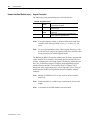
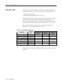
The following table defines the MV SMC-Flex PTC thermistor input and
response ratings:
%5-"%.0*UNE
Product Overview
1-15
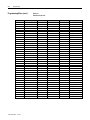
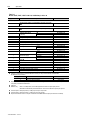
Table 1.A – PTC Input Ratings
Response Resistance
Reset Resistance
Short-circuit Trip Resistance
Maximum Voltage at PTC Terminals (RPTC = 4 kΩ)
Maximum Voltage at PTC Terminals (RPTC = open)
Maximum Number of Sensors
Maximum Cold Resistance of PTC Sensor Chain
Response Time
3400 Ω ± 150 Ω
1600 Ω ± 100 Ω
25 Ω ± 10 Ω
< 7.5 V
30 V
6
1500 Ω
800 ms
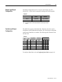
The following figure illustrates the required PTC sensor characteristics,
per IEC-34-11-2.
4000
1330
550
250
100
20
10
-20°C
0°C
TNF+15K
TNF-20K
TNF- 5K
TNF+ 5K
TNF
Figure 1.13 – PTC Sensor Characteristics per IEC-34-11-2
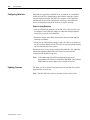
PTC Trip
The MV SMC-Flex will trip with a PTC indication if:
• No other fault currently exists
• PTC protection is enabled
• The resistance across terminals 23 and 24 is either greater than the
relay’s response resistance or less than the short-circuit trip resistance.
%5-"%.0*UNE
1-16
Product Overview
Protection and Diagnostics
(cont.)
Open Gate
An open-gate fault indicates that improper SCR firing, typically caused by
an open SCR gate or driver system, has been detected on one of the power
poles. Before the controller shuts down, it will attempt to start the motor a
total of three times (or as programmed in Parameter 82).
An open gate is detected when the module sends a gate signal to the SCRs
but does not detect that they turned on. SCR turn-on is detected when the
voltage across the leg (L-T) collapses.
Line Faults
The MV SMC-Flex™ controller continually monitors line conditions for
abnormal factors. Pre-start protection includes:
• Line Fault (with phase indication)
– Line voltage loss
– Missing load connection
– Shorted SCR
Running protection includes:
• Line Fault (no phase indication)
– Line voltage loss
– Missing load connection
Phase reversal protection : can be toggled either ON or OFF.
:
%5-"%.0*UNE
Phase reversal protection is functional only at pre-start.
Product Overview
1-17
Excessive Starts/Hour
The MV SMC-Flex™ module allows the user to program the desired
number of starts per hour (up to 99). This helps eliminate motor stress
caused by repeated starting over a short time period.
Note: The base rating of the MV SMC-Flex is two starts (thirty seconds
each max.) per hour. Applications requiring more frequent starts, or longer
duration starts, should be reviewed with the factory to avoid equipment damage.
Overtemperature
The power module temperature is monitored during starting and stopping
maneuvers by thermistors. The thermistor is connected to the gate driver
board where it is processed, and the status is transmitted by fibre-optic
cable through the interface board to the control module. When an
overtemperature condition exists (>85°C), the control module trips and
indicates a "PTC Power Pole" fault.
An overtemperature condition could indicate high ambient temperature,
overloading or excessive cycling. After the power module temperature is
reduced to allowable levels, the fault can be cleared (see page 9-1 for
instructions).
Metering
Power monitoring parameters include:
•
•
•
•
•
•
•
•
Three-phase current
Three-phase voltage
Power in MW
Power usage in MWh
Power factor
Motor thermal capacity usage
Elapsed time
Motor speed (100%, with use of optional tachometer input)
Notes:
1. Voltage measurement is not available during the braking operation of
the SMB Smart Motor Braking, Accu-Stop, and Slow Speed with
Braking control options.
2. The elapsed time and MWh values are automatically saved to memory
every 12 hours.
3. Motor thermal capacity usage is determined by the built-in electronic
thermal overload. An overload fault occurs when this value reaches
100%.
%5-"%.0*UNE
1-18
Product Overview
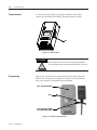
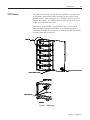
Communication
A serial interface port (DPI) is provided as standard, which allows
connection to the Bulletin 20-HIM LCD human interface modules.
DPI
Figure 1.14 – DPI Location
ATTENTION
Two peripheral devices can be connected to the DPI.
The maximum output current through the DPI is 280 mA.
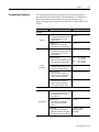
Programming
Setup is easy with the built-in keypad and three-line, sixteen-character
backlit LCD. Parameters are organized in a three-level menu structure,
using a text format for straightforward programming.
Port 5 – DPI Communications
Port 2
Ports 2 and 3 when two HIMs
are connected with a splitter
Figure 1.15 – Built-in Keypad and LCD
%5-"%.0*UNE
Product Overview
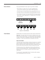
Status Indication
1-19
Four programmable hard contact outputs are provided as standard:
• The Auxiliary #1 Contact is N.O. It is always programmed for
Up-to-speed to control the bypass contactor in MV applications.
• The fault Contact is for fault indication and is programmable for N.O./N.C.
• The alarm Contact is for alarm indication and is programmable for N.O./N.C.
• The Auxiliary #2 Contact is for normal indication and is programmable
for N.O./N.C. For MV applications, it is configured as N.O. to control
the line contactor.
11
12
13
14
15
16
17
18
SMC-Flex
Control Terminals
23
24
PTC
Input
25
26
TACH
Input
19
20
21
22
33
34
Aux #1
Up-to-Speed
27
28
Ground
Fault
29
30
Fault
Contact
31
32
Alarm
Contact
Aux #2
Normal
Figure 1.16 – Control Terminals
Control Options
The MV SMC-Flex™ controller offers the control options described below.
Important: The options listed in this section are mutually exclusive and
must be specified when ordering. An existing controller may be upgraded
to another control option by replacing the control module and possibly other
components. Consult your nearest Rockwell Automation sales office.
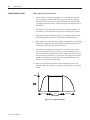
Pump Control Option
This option reduces surges during the starting and stopping of a centrifugal
pump by smoothly accelerating and decelerating the motor. The microprocessor analyzes the motor variables and generates commands that control
the motor and reduce the possibility of surges occurring in the system.
The motor current will vary during the acceleration period, and may be
near the motor rated starting current. The pump algorithm does not limit
starting current since full voltage is needed to reach full speed with a
loaded motor.
The starting time is programmable from 0-30 seconds, and the stopping
time is programmable from 0-120 seconds.
%5-"%.0*UNE
1-20
Product Overview
Control Options (cont.)
Pump Application Considerations
1. Consult factory if start time settings over 30 seconds are required.
The base rating of the MV SMC-Flex is two starts (or one start/stop
combination) per hour, thirty seconds maximum for each operation.
A stopping operation counts as a start for purposes of thermal capacity
calculations.
2. The Pump Control option functions only for centrifugal pumps. It is
not suited for positive displacement, piston, or other types of pumps.
3. The Pump Stop option functions only for a centrifugal pump running
at greater than approximately 2/3 of the motor rated horsepower.
4. Pump applications with input and/or output valves that are closed during
starting and/or stopping may not benefit from the Pump Control option.
Consult the factory for applications with valves.
5. For starting or stopping times longer than 15 seconds, power fuse
selection should be reviewed to ensure no element damage occurs.
The fuse minimum melting time-current characteristic curve should
be consulted to ensure that, at 1.1 times the full voltage locked rotor
current of the motor, the actual starting or stopping time does not
exceed 75% of the fuse melting time.
6. Motor overload and/or upstream breaker settings may have to be
adjusted to allow the starting or stopping current to flow for extended
periods.
100%
Motor
Speed
Pump Start
Run
Time (seconds)
Figure 1.17 – Pump Control Option
%5-"%.0*UNE
Pump Stop
Product Overview
1-21
ATTENTION
Pump stopping is not intended to be used as an
emergency stop. Refer to the applicable standard for
emergency stop requirements.
ATTENTION
Pump stopping may cause motor heating depending on
the mechanical dynamics of the pumping system.
Therefore, select the lowest stopping time setting that
will satisfactorily stop the pump.
Braking Control Option
The Braking Control option (Smart Motor Braking, Accu-Stop and Slow
Speed with Braking) are not offered for standard use in MV applications.
Please consult factory for further assistance.
%5-"%.0*UNE
1-22
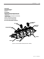
Product Overview
Hardware Description
The following sections contain descriptions of system components and
system operation. Each section will be described to give the user an
understanding of the MV SMC-Flex to facilitate operation and maintenance
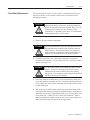
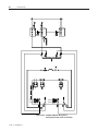
of the system. Refer to Figures 1.18 through 1.21, Typical MV SMC-Flex
Power System.
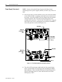
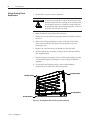
Power Module
The controller consists of three power modules, one for each phase. Each
power module consists of incoming and outgoing terminals for cables, SCRs,
heatsink and clamp assembly. The SCRs are connected in inverse parallel
(and in series for 12- or 18-SCR assemblies) to form a three-phase, AC
line controller configuration.
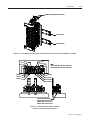
Each power module includes a snubber circuit to limit the rate of rise in
voltage across each SCR pair. The module also includes patented gate
driver circuits which derive their power from the snubber circuit.
Voltage sharing resistors are connected across each SCR pair to provide
static voltage balance for series-connected SCRs. These resistors are
tapped to provide a reference for overvoltage protection circuitry on the
gate driver board.
A voltage sensing board is used to reduce the line-side and load-side voltages
to lower levels that can be measured by the SMC-Flex control module.
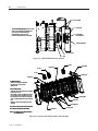
Self-Powered Silicon-Controlled Rectifier Gate Driver Board
This board provides the turn-on capability for SCR devices. The board
also provides optical fibre isolation between itself and the gating source
logic. It is powered by recovering energy from the snubber circuit, so it is
fully isolated from the control and logic circuits; it is self-economizing
when the unit is not running, or is in bypass mode.
Note: If pump control or stop control are used, the gate driver boards are
powered continuously using separate power supply boards. (Refer to
Chapter 8 for additional details.)
The MV SMC-Flex has three heatsinks fitted with a thermistor to monitor
temperature rise. The circuitry on the gate driver board accepts the
thermistor, and drives a fibre-optic cable if the temperature is below the
setpoint (85°C). If the temperature rises above the setpoint, the driver is
turned off, and the MV SMC-Flex is signalled to stop gating and initiate a
temperature fault.
Due to the self-powered nature of the circuits, this function is active only
while the SMC is active. While the starter is off, or in bypass, no power is
dissipated in the SCRs and the temperature of the SCRs can only decrease.
%5-"%.0*UNE
Product Overview
1-23
Interface Board
This circuit board takes current transformer signals plus line-side and loadside voltage feedback signals from the voltage sensing board and passes
them to the SMC-Flex for processing. The control module produces gating
signals for the SCRs, which are received on the interface board, and used
to drive fibre-optic transmitters. The gating signals are sent to the gate-driver
circuit board via fibre-optic cables. The interface board also receives
temperature feedback from the gate-driver board via fibre-optic cable(s).
If the heatsink temperature rises above a set value, a signal is sent to the
SMC-Flex to stop gating the SCRs and initiate a temperature fault.
For a detailed layout of this circuit board, refer to Figure 3.2 on page 3-6.
%5-"%.0*UNE
1-24
Product Overview
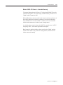
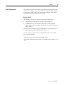
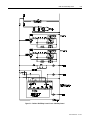
*
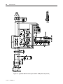
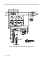
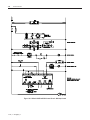
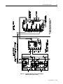
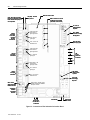
Figure 1.18 – Typical MV SMC-Flex Power System • Bulletin 1562E (Without Stop Control)
%5-"%.0*UNE
Product Overview
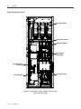
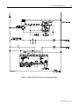
1-25
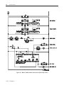
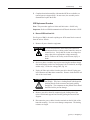
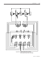
Figure 1.19 – Typical MV SMC-Flex Power System • Bulletin 1562E (With Stop Control)
%5-"%.0*UNE
1-26
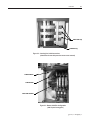
Product Overview
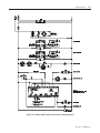
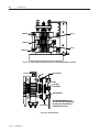
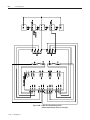
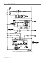
Figure 1.20 – Typical MV SMC-Flex Power System • Bulletin 1560E (Without Stop Control)
%5-"%.0*UNE
Product Overview
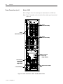
1-27
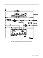
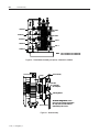
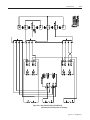
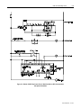
Figure 1.21– Typical MV SMC-Flex Power System • Bulletin 1560E (With Stop Control)
%5-"%.0*UNE
1-28
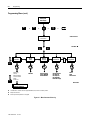
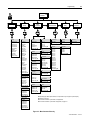
Product Overview
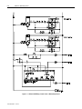
Functional Description
The following functional descriptions and associated control circuits are
for units using IntelliVAC contactor control modules. For units with
electromechanical (relay) control, refer to Appendix C.
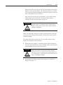
Bulletin 1562E • Basic Control – Controlled Start only
When wired as shown in Figure 1.22, the controller operates as follows:
Pressing the "Start" button initiates the start sequence. Relay "CR" closes
and applies control power to terminal 17 of the SMC-Flex module. The
auxiliary contact #2 ("Normal") closes, energizing "M-IV" and "MC",
which completes the hold-in circuit on the start button, and closes the main
contactor.
The SMC-Flex module examines the line voltage, looks for fault
conditions, checks phase rotation, calculates zero crossing information, and
begins gating the SCRs to start the motor.
When the motor approaches rated speed, the SMC-Flex module closes the
"AUX1" (up-to-speed) auxiliary contacts, energizing "B-IV", which closes
the bypass contactor. The motor then runs at full line voltage.
When the "Stop" button is pressed, the "CR" relay opens terminal 17 on
the SMC-Flex module. The "Normal" contact opens, dropping out the
main contactor, allowing the motor to stop. The "AUX1" contact is held
closed for a short time by the control module. This holds the bypass
contactor closed for about 10 seconds to protect the power electronics from
any voltage transients due to opening the motor circuits.
%5-"%.0*UNE
Product Overview
1-29
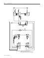
Bulletin 1562E • Basic Control – With Controlled Stop
When wired as shown in Figure 1.23, the controller operates in much the
same manner as in Figure 1.22.
Terminal 16 on the SMC-Flex module now controls the start and stop
maneuvers. Terminal 16 must remain energized for the module to run.
When the “Stop” button is pressed, and “CR” opens, the SMC-Flex module
will initiate the option stop. An uncontrolled, or coast stop, is achieved by
opening the connection to terminal 17. This contact should remain open to
ensure all hold-in contacts clear, to prevent a re-start.
If the motor has started, the unit is in the bypass mode, and a trip occurs
within the SMC-Flex module or from an external protection relay; "AUX2"
will open the line contactor immediately, and "AUX1" will remain closed
for 10 seconds. A trip due to an overload or fault condition will result in a
“coast” stop.
Bulletin 1562E • DPI Control – Controlled Start only
The control scheme shown in Figure 1.24 allows the MV SMC-Flex to be
controlled using DPI (Drive Programming Interface). This special usage of
DPI includes provisions for a "Hand" mode of control as well.
With the Hand-Auto selector switch in the "Auto" position, terminal 18 of
the SMC-Flex module is energized, allowing a start command to be
executed via DPI. The "AUX2" contact closes, energizing both "M-IV"
and "MC".
When the motor approaches rated speed, the SMC-Flex module closes
"AUX1", energizing "B-IV", which closes the bypass contactor.
To run in "Hand" mode, the "CR" contact is used to initiate a start
sequence (similar to Figure 1.22).
A stop command can be generated via DPI or by opening "CR", depending
on the control mode.
%5-"%.0*UNE
1-30
Product Overview
Functional Description (cont.)
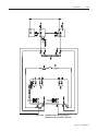
Bulletin 1560E • Basic Control – Controlled Start Only
The Bulletin 1560E is intended for addition to an existing motor
controller, which provides circuit isolation, motor switching, and
overload and overcurrent protection. When wired as shown in Figure
1.25, the controller operates as follows:
When a start is initiated in the existing motor controller and the contactor
(or breaker) closes, a contact must be supplied to tell the 1560E to start
also. A "CR" contact will apply control voltage to terminal 17 of the
SMC-Flex module.
When stopping the motor, the contactor in the existing controller will
open, removing power from the motor, and then the “CR” relay. The
bypass hold-in rung will keep the bypass contactor closed for a short time.
The “Fault” contact on the SMC-Flex module should be wired into the
existing controller to trip the main contactor (or breaker) in the event of a
fault condition sensed by the SMC-Flex module.
If possible, it is better to have the SMC-Flex module control the main
contactor directly. In this case, the control circuit would look like, and
function like, the descriptions above for the Bulletin 1562E.
Bulletin 1560E • Basic control – With Controlled Stop
When wired as shown in Figure 1.26, the controller operates much the
same as described above for the Standard module. The control signal uses
terminal 16 instead of 17, and a “coast” stop can be achieved by opening
the connection to terminal 17.
It is more important in this configuration to integrate the control circuit of
the 1560E with the existing controller, for better control of the Stop
option. The “start signal” for this scheme cannot be a slave of the main
contactor, since it must remain closed to accomplish the option stop
maneuver. The SMC-Flex module can be used to control the main
contactor such that it will close when a start is initiated, and remain closed
until it has sensed the motor has stopped following an option stop
maneuver.
%5-"%.0*UNE
Product Overview
1-31
Bulletin 1560E • DPI Control – Controlled Start only
The control scheme shown in Figure 1.27 allows the MV SMC-Flex to be
controlled using DPI. This special usage of DPI includes provisions for a
"Hand" mode of control as well.
With the Hand-Auto selector switch in the "Auto" position, and closure of
the existing starter main contactor, terminal 18 is energized, allowing a
start command to be executed via DPI. "AUX2" serves as an interlock
with the main contactor (or breaker) in the existing starter.
As with the other control schemes, the SMC-Flex module closes "AUX1",
energizing "B-IV", as the motor approaches rated speed.
Hand control is enabled with the selector switch in the "Hand" position.
Closure of the "Start" relay, from the existing starter, allows the unit to
initiate motor soft starting.
%5-"%.0*UNE
1-32
Product Overview
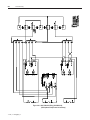
Figure 1.22 – Bulletin 1562E IntelliVAC Control Circuit • Without Stop Control
%5-"%.0*UNE
Product Overview
1-33
Figure 1.23 – Bulletin 1562E IntelliVAC Control Circuit • With Stop Control
%5-"%.0*UNE
1-34
Product Overview%5-"%.0*UNE
Figure 1.24 – Bulletin 1562E IntelliVAC Control Circuit
• With DeviceNet (or DPI) Communication and optional Hand/Auto
%5-"%.0*UNE
Product Overview
1-35
Figure 1.25 – Bulletin 1560E IntelliVAC Control Circuit • Without Stop Control
%5-"%.0*UNE
1-36
Product Overview
Figure 1.26 – Bulletin 1560E IntelliVAC Control Circuit • With Stop Control
%5-"%.0*UNE
Product Overview
1-37
Figure 1.27 – Bulletin 1560E IntelliVAC Control Circuit
• DeviceNet (or DPI) Communication and optional Hand/Auto
%5-"%.0*UNE
1-38
Product Overview
%5-"%.0*UNE
Chapter
2
Installation
ATTENTION
Perform the installation duties correctly. Errors may
cause commissioning delays, equipment damage or
personal injury.
Important: For the 1503E, refer to applicable documentation from OEM
installation, grounding, interlocking and wiring. This manual should be
utilized in conjunction with the OEM supplied documentation, and is
suitable for commissioning, programming, calibration, metering, serial
communications, diagnostics, troubleshooting, and maintenance of a
standard solid-state controller.
Receiving
Safety and Codes
Unpacking and Inspection
It is the responsibility of the user to thoroughly inspect the equipment
before accepting the shipment from the freight company. Check the item(s)
received against the purchase order. If any items are damaged, it is the
responsibility of the user not to accept delivery until the freight agent has
noted the damage on the freight bill. Should any concealed damage be
found during unpacking, it is again the responsibility of the user to notify
the freight agent. The shipping container must be left intact and the freight
agent should be requested to make a visual inspection of the equipment.
ATTENTION
The Canadian Electrical Code (CEC), National Electrical
Code (NEC), or other local codes outline provisions for
safely installing electrical equipment. Installation
MUST comply with specifications regarding wire type,
conductor sizes, branch circuit protection, interlocking
and disconnect devices. Failure to do so may result in
personal injury and/or equipment damage.
After unpacking the material, check the item(s) received against the bill of
lading to ensure that the nameplate description of each item agrees with
the material ordered. Inspect the equipment for physical damage, as stated
in the Rockwell Automation Conditions of Sale.
Remove all packing material, wedges, or braces from within the controller.
Operate the contactors and relays manually to ensure that they operate freely.
Store the equipment in a clean, dry place if it will not be installed immediately
after unpacking. The storage temperature must be between -20°C and 75°C
(-4°F and 167°F) with a maximum humidity of 95%, non-condensing, to
guard against damage to temperature sensitive components in the controller.
%5-"%.0*UNE
2-2
Installation
General Precautions
Transportation and Handling
In addition to the precautions listed throughout this manual, the following
statements, which are general to the system, must be read and understood.
ATTENTION
The controller contains ESD (electrostatic discharge)
sensitive parts and assemblies. Static control
precautions are required when installing testing,
servicing, or repairing the assembly. Component
damage may result if ESD control procedures are not
followed. If you are not familiar with static control
procedures, refer to applicable ESD protection handbooks.
ATTENTION
An incorrectly applied or installed controller can
damage components or reduce product life. Wiring or
application errors, such as undersizing the motor,
incorrect or inadequate AC supply, or excessive ambient
temperatures, may result in malfunction of the system.
ATTENTION
Only personnel familiar with the controller and associated
machinery should plan or implement the installation,
start-up, and subsequent maintenance of the system.
Failure to do this may result in personal injury and/or
equipment damage.
The controller must be transported on a pallet or via use of the lifting
angles supplied as part of all 90-inch (2.3 m) high cabinets or frame units.
ATTENTION
Ensure that the load rating of the lifting device is
sufficient to safely raise the controller sections. Failure
to do so may result in severe injury and/or equipment
damage. Refer to the packing slip enclosed with shipment
for shipping weights.
Round rollers can be used to assist in moving the controller to the installation site. Once at the final site, the pipe rolling technique can be used to
place the cabinet in the desired position.
ATTENTION
%5-"%.0*UNE
Care must be exercised when using either a forklift, or
the pipe rolling technique, for positioning purposes to
ensure that the equipment is not scratched, dented or
damaged in any manner. Always exercise care to
stabilize the controller during handling to guard against
tipping and injury to personnel.
Installation
Installation Site
2-3
Consider the following when selecting the installation site:
A. The operating ambient temperature should be between 0°C and 40°C
(32°F and 104°F) for NEMA Type 1 or 12 enclosures. For higher
ambient conditions, please consult Rockwell Automation factory.
B. The relative humidity must not exceed 95%, non-condensing. Excessive
humidity can cause electrical problems from corrosion or excessive
dirt build-up.
C. The equipment must be kept clean. Dust build-up inside the enclosure
inhibits proper cooling and decreases the system reliability. The
equipment should not be located where liquid or solid contaminants can
drop onto it. Controllers with ventilated enclosures (in particular those
with fans) must be in a room free of airborne contaminants.
D. Only persons familiar with the function of the controller should have
access to it.
E. The losses in the controller produce a definite heat dissipation,
depending on the unit size, that tends to warm the air in the room.
Attention must be given to the room ventilation and cooling requirements to ensure that the proper environmental conditions are met.
F. Operational altitude is 3,300 feet (1 km) maximum without derating.
Higher altitudes may require optional components. Please consult
Rockwell Automation factory.
G. The area of the controller should be free of radio frequency interference
such as encountered with some welding units. This may cause erroneous
fault conditions and shut down the system.
ATTENTION
An incorrectly applied or installed controller can result in
component damage or a reduction in product life. Wiring
or application errors, such as, undersizing the motor,
incorrect or inadequate AC supply, or ambient temperatures above or below the specified temperature range may
result in malfunction of the controller.
Mounting
The 1503E, 1560E and 1562E are designed to be mounted in the vertical
position. Standard cabinet drawings with certified dimension drawings can
be obtained by contacting your local Rockwell Automation Sales office for
the 1560E/1562E. Please refer to OEM documentation for the 1503E.
Refer to drawings for mounting requirements.
%5-"%.0*UNE
2-4
Installation
Installation Site (cont.)
Grounding Practices
The purpose of grounding is to:
A. Provide safety for Personnel.
B. Limit dangerous voltages to ground on exposed parts.
C. Facilitate proper overcurrent device operation under ground fault
conditions.
D. Provide for electrical interference suppression.
Important: Generally, grounding should be in accordance with the
Canadian Electrical Code (CEC) or National Electrical Code (NEC) and
other local codes.
Each power feeder from the substation transformer to the controller must
be equipped with properly sized ground cables. Simply utilizing the
conduit or cable armour as a ground is not adequate. The conduit or cable
armour and ground wires should be bonded to ground at both ends. Each
enclosure and/or frame must be bonded to ground at a minimum of two
locations.
Each AC motor frame must be bonded to grounded building steel within 20
feet (6.1 m) of its location and tied to the controller’s ground bus by ground
wires within the power cables and/or conduit. The conduit or cable armour
should be bonded to ground at both ends.
ATTENTION
Recommended Torque Values
Any instruments used for test or troubleshooting should
have their case connected to ground for safety. Failure
to do so may result in damage to equipment or personal
injury.
When reinstalling components or when reassembling the cabinet, tighten
the following bolt sizes to the specified torque values:
1/4-in. hardware
6 ft-lb. (8 N-m)
5/16-in. hardware
12 ft-lb. (15 N-m)
3/8-in. hardware
20 ft-lb. (27 N-m)
1/2-in. hardware
48 ft-lb. (65 N-m)
NOTE: For 3/8 in. hardware in the 'T'-slots of aluminum heatsinks, the
recommended torque is 16 ft-lb (22 N-m). Do not overtorque these
connections as the slots will be damaged and the connection will be
compromised.
%5-"%.0*UNE
Installation
Power Connections
2-5
The controller requires a three-phase supply and an equipment grounding
conductor to earth ground. A neutral conductor of the three-phase supply
is not necessary and is usually not routed to the controller. Three-phase
wiring will connect the controller to the motor.
Bulletin 1562E
The Bulletin 1562E unit is available in two main configurations:
1. A modified two-high cabinet (180/360A, 2400 to 4160 V)
2. A combination of a one-high full voltage non-reversing (FVNR)
cabinet and a 1560E unit (600A, 2400 to 4160 V, and 180/360/600A,
5500 to 6900 V)
To make power connections for a two-high cabinet, refer to Figures 2.1 to
2.3, and Publication 1500-UM055B-EN-P (Chapter 2).
To make power connections for a one-high FVNR cabinet and a 1560E
unit, proceed as follows:
• Make line connections within the one-high cabinet
• Make load connections at the 1560E CT terminals (refer to Figure 2.5 or
2.6)
%5-"%.0*UNE
2-6
Installation
Power Connections (cont.)
Power Stack Assembly
Bypass Vacuum Contactor
Voltage Sensing Module
Non Load Break
Isolation Switch
Load Cable Connection
Point (top exit)
Line Vacuum Contactor
Current Transformers
Figure 2.1 – Cabinet Layout • 1562E – 180/360 A, 2400 V to 4160 V
(with LV panels not shown)
%5-"%.0*UNE
Installation
2-7
Power Cable Lugs
Ground Bus Lug
Figure 2.2 – Incoming Line Cable Connections
(viewed from the rear with power bus access cover removed)
Cable Duct Barrier
Cable Duct Boot
Motor Cable Terminals
Figure 2.3 – Bottom Cable Exit Configuration
(with LV panel swung open)
%5-"%.0*UNE
2-8
Installation
Power Connections (cont.)
Bulletin 1560E
Refer to Figures 2.4 to 2.6 to make power connections for a 1560E unit.
Note: The CT assembly can be oriented to allow either top or bottom load
cable exit.
Phase 2
Power Stack Assembly
Phase 1
Power Stack Assembly
Phase 3
Power Stack Assembly
Line Connections
Phase 1 (top)
through 3 (bottom)
Load Connections
(top exit shown)
Phase 1 (front)
through 3 (back)
Bypass Vacuum Contactor
Current Transformers
Figure 2.4 – Power Connections • 1560E – 180/360A, 2400 to 4160 V
%5-"%.0*UNE
Installation
2-9
Phase 1
Line Connection
Phase 1
Power Stack Assembly
Phase 2
Line Connection
Phase 2
Power Stack Assembly
Load Connections
(top exit shown)
Phase 1 (front)
through 3 (back)
Phase 3
Power Stack Assembly
Current Transformers
Phase 3
Line Connection
Voltage Sensing Module
Bypass Vacuum Contactor
Figure 2.5 – Power Connections • 1560E – 180/360A, 5500 to 6900 V
%5-"%.0*UNE
2-10
Installation
Power Connections (cont.)
Phase 1
Line Connection
Phase 1
Power Stack Assembly
Phase 2
Line Connection
Load Connections
(top exit shown)
Phase 1 (front)
through 3 (back)
Phase 2
Power Stack Assembly
Current Transformers
Phase 3
Line Connection
Phase 3
Power Stack Assembly
Bypass Vacuum Contactor
Voltage Sensing Module
Figure 2.6 – Power Connections • 1560E – 600A, 2400 to 6900 V
%5-"%.0*UNE
Installation
2-11
Important: For retrofit units (Bul. 1560E), the CEC and NEC require that
branch-circuit protection of the AC line input to the controller be provided
by a circuit breaker or motor starter. This function is included with a
Bulletin 1562E.
Important: The control and signal wires should be positioned at least
six (6) inches (150 mm) from power cables. Additional noise suppression
practices (including separate steel conduits for signal leads, etc.) are
recommended.
Bulletin 1503E
For 1503E, refer to applicable documentation from OEM for installation,
grounding, interlocking and wiring. This manual should be utilized in
conjunction with the OEM supplied documentation, and is suitable for
commissioning, programming, calibration, metering, serial communications, diagnostics, troubleshooting, and maintenance of a standard solidstate controller.
%5-"%.0*UNE
2-12
Installation
Power Wiring
The wire sizes must be selected individually, observing all applicable
safety and CEC or NEC regulations. The minimum permissible wire size
does not necessarily result in the best operating economy. The minimum
recommended size for the wires between the controller and the motor is the
same as that used if a main voltage source connection to the motor was used.
The distance between the controller and motor may affect the size of the
conductors used.
Consult the wiring diagrams and appropriate CEC or NEC regulations to
determine correct power wiring. If assistance is needed, contact your area
Rockwell Automation Sales Office.
Interlocking
Hinged doors and panels, which provide access to medium voltage
components, must be mechanically interlocked to ensure circuit isolation.
If a combination MV SMC-Flex (1562E) is purchased from Rockwell
Automation, all medium voltage compartments will be mechanically
interlocked such that they cannot be opened unless the isolating switch for
the unit is open. Each medium voltage door is interlocked to the isolating
switch handle. To open the doors, move the isolating switch to the OFF
position and loosen the two retaining bolts on the main power cell door.
Once this door is open, the other doors may be opened in sequence,
depending on the specific interlock scheme provided. The retrofit-type
MV SMC-Flex (1560E) is intended to be added to an existing motor
controller, and has no isolating means included.
ATTENTION
For 1503E and 1560E, it is the responsibility of the
installer/user to ensure the equipment interlocking
scheme is in place and functional before energizing the
equipment. Inadequate interlocking could expose
personnel to energized parts which could result in severe
burns, injury or death.
NOTE: Rockwell Automation can assist with the selection of an appropriate interlocking method, which may include mechanical modifications
to the cabinet(s) or key-type lock systems.
NOTE: An auxiliary cabinet may be attached to the main structure. It will
be ram-interlocked with the main power cell door, which will not allow it
to be opened until the main power cell door is opened.
%5-"%.0*UNE
Installation
Installation
2-13
Physical Location
The controller is designed for limited front access (components may have to
be removed) and should be installed with adequate and safe clearance to
allow for total door opening. The back of the unit may be placed against a
wall and several units may be set end to end. In special cases where floor
space is limited and the unit is not against a wall, certain cabinet sections
may be placed back to back. This requirement must be stated in the specifications in order to mechanically alter the controller.
Fan
The controller may include a cooling fan which is used to cool the component.
It should be checked for free operation and no obstruction of the airflow.
Ground Bus Bar
Controllers which are delivered in two (or more) sections, or retrofit controllers,
will require that the ground bus bar (6 mm x 51 mm) [¼ in. x 2 inches],
which runs the entire length of the equipment in the center back side, be
reconnected. A mechanical lug for #8-#10 AWG or #6-250 MCM cable is
supplied at the incoming end of the line-up. When the sections are brought
together, bus links are used to connect the bus bars.
Important: Refer to 2-high, Series B drawings in Publication
1500-UM055B-EN-P for power/ground bus connection.
Power and Control Wiring
Controllers consisting of two or more sections will require that the power
and control wiring be connected per the schematic drawings provided.
Control Cables
Control cable entry/exit should be located near the terminal blocks; customer’s
connections are to be routed along the empty side of the terminals. Nylon
cable tie loops are provided at the left, front corner of the cabinet to route
control cables safely behind the low voltage panel hinges. Cables should
be routed so they do not interfere with the swing of the low-voltage panels.
Fibre-Optic Cables
The small, gray, fibre-optic cables are fragile and must be protected during
installation from sharp bends and impact.
%5-"%.0*UNE
2-14
Installation
Installation (cont.)
Power Factor Correction Capacitors
The controller can be installed on a system with power factor correction
capacitors. The capacitors must be located on the line side of the controller.
This is required to prevent damage to the SCRs in the MV SMC-Flex
controller. A separate switching contactor is recommended to apply the
capacitors only after the bypass contactor has closed, and to remove them
when the bypass contactor opens. See Figure 2.7 for two different
acceptable connection methods.
NOTE: Consult the factory if there are any capacitors on the same
branch circuit as the MV SMC-Flex.
When discharged, a capacitor has essentially zero impedance. For
switching, sufficient impedance should be connected in series with the
capacitor bank to limit the inrush current. A method of limiting the surge
current is to add inductance in the capacitor conductors. This can be accomplished by putting turns or coils of wire in the power connections to the
capacitors (6-inch diameter coil, six loops). For more information, refer
to NEMA standard ICS 2, Part 2, Capacitor Applications.
Care should be used in mounting the coils so that they are not stacked
directly on top of each other or they will have a cancelling effect. Also,
the coils should be mounted on insulated supports away from metal parts
so they will not act like induction heaters.
ATTENTION
%5-"%.0*UNE
Any covers or barriers removed during installation must
be replaced and securely fastened before energizing
equipment. Failure to do so may result in severe burns,
injury or death.
Installation
2-15
Power Bus
Isolation Switch
Isolation Switch
Fuse
Fuse
Contactor
Isolation Contactor
di/dt Inductor
di/dt Inductor
Capacitor
Contactor
PFCC
PFCC
(Power Factor
Correction Capacitor)
Bypass
Contactor
Motor
Figure 2.7 – Typical One-Line Diagram
(Showing 2 Different Styles of Power Factor Capacitor Connections)
%5-"%.0*UNE
2-16
Installation
Surge Arrestor Protection
Devices
%5-"%.0*UNE
Rockwell Automation highly recommends that motor surge capacitors and/or
motor surge arresters not be located on the load side of the SMC. The
issues that warrant this are:
•
Motor and system inductance limits the rate at which the current can
change through the SMC. If capacitance is added at the motor, the
inductance is negated. The surge capacitors downstream of the SMC
represent a near zero impedance when presented with a step voltage
from the turn on of the SCRs near the line voltage peak. This causes a
high level of di/dt to occur, due to the fact that the motor cables are
generally short in length. There is very little impedance between the
capacitor and SCR to limit the di/dt of this capacitor charging current.
This can result in damage to the power semiconductors (SCRs) in the
SMC.
•
It is essential to understand the clamping voltage of the arresters and
type of grounding used in the distribution system. The switching of the
SCRs generates slightly higher than nominal peak line to ground
voltages. The typical peaks are 1.5 times the nominal line to ground
peak voltages. These may cause the arresters to conduct, which could
affect the operation of the SMC and result in faults. Depending upon
the instance at which the arresters conduct, this could also result in
SCR damage.
•
The capacitance in combination with the line and motor impedance
could also be excited by the voltage steps from SCR switching to
create resonant voltage swings which could exceed the device voltage
withstanding ratings or surge arrester rating, or cause distorted voltage
signals which may be misinterpreted by the MV SMC-Flex control
system.
Installation
Motor Overload Protection
2-17
Thermal motor overload protection is provided as standard (though it must
be programmed) with the MV SMC-Flex controller. If the overload trip
class is less than the acceleration time of the motor, nuisance tripping may
occur.
ATTENTION
Overload protection should be properly coordinated with
the motor to avoid damage to equipment.
Two special applications require consideration: Two-speed Motors, and
Multi-motor Protection.
Two-speed Motors
The MV SMC-Flex controller has overload protection available for single
speed motors. When the MV SMC-Flex controller is applied to a two-speed
motor, the Overload Class parameter must be programmed to OFF, and
separate overload relays must be provided for each speed.
Multi-motor Protection
The MV SMC-Flex controller provides overload protection for only one
motor. When the MV SMC-Flex is controlling more than one motor, the
Overload Class Parameter must be programmed to OFF, and individual
overload protection is required for each motor.
%5-"%.0*UNE
2-18
Installation
EMC Compliance
ATTENTION
This product has been designed for Class A equipment.
Use of the product in domestic environments may cause
radio interference, in which case, the installer may need
to employ additional mitigation methods.
The following guidelines are provided for EMC installation compliance.
Enclosure
Install the product in a grounded metal enclosure.
Wiring
Wire in an industrial control application can be divided into three groups:
power, control, and signal. The following recommendations for physical
separation between these groups is provided to reduce the coupling effect.
• Different wire groups should cross at 90° inside an enclosure.
• Minimum spacing between different wire groups in the same tray should
be 16 cm (6 in.).
• Wire runs outside an enclosure should be run in conduit or have
shielding/armor with equivalent attenuation.
• Different wire groups should be run in separate conduits.
• Minimum spacing between conduits containing different wire groups
should be 8 cm (3 in.).
• For additional guidelines, please refer to Wiring and Ground guidelines,
publication DRIVES-IN001A-EN-P.
• Wire earth ground to control terminal 14.
• Use shielded wire for: PTC Input
Tach Input
Ground Fault Input
• Terminate shielded wires to terminal 14.
• Ground fault CT must be inside or within 3 m of metal enclosure.
%5-"%.0*UNE
Installation
2-19
• To meet produce susceptibility requirements, ferrite cores need to be
added to the communication lines. All cores specified below are the split
core type, so they can be added to existing connections.
– When using an external HIM (or DPI interface), a core should be
added to the HIM cable near the SMC-Flex control module. The
recommended core is Fair-Rite no. 0431167281 or equivalent.
– When using DeviceNet, two cores need to be added to the DeviceNet
cable near the SMC-Flex control module. The recommended cores are
TDK ZCAT2033 0930H and TDK ZCAT2035 0930 or equivalent.
Control Power
Control Voltage
The SMC-Flex controller will accept a control power input of 100 to 240V
AC, (-15 / +10%), 1 phase, 50/60 Hz. Refer to the product nameplate to
verify the control power input voltage.
Connect control power to the controller at terminals 11 and 12. The control
power requirement for the control module is 75 VA. Depending on the
specific application, additional control circuit transformer VA capacity
may be required.
Control Wiring
Table 2.C provides the control terminal wire capacity and the tightening
torque requirements. Each control terminal will accept a maximum of two
wires.
Table 2.C – Control Wiring and Tightening Torque
Wire Size
Torque
0.75 to 2.5 mm2 (#18 to #14 AWG)
0.6 Nm (5 lb-in.)
%5-"%.0*UNE
2-20
Installation
Control Terminal Designations
As shown in Figure 2.10, the SMC-Flex controller contains 24 control
terminals on the front of the controller.
Figure 2.10 – SMC-Flex Controller Control Terminals
Terminal
Number
11
12
13
14
15
16
17
18
19
20
21
22
Description
Control Power Input
Control Power Common
Control Enable Input :
Control Module Ground
Option Input #2 :
Option Input #1 :
Start Input :
Stop Input :
N.O. Aux. Contact #1 (Up-to-Speed) ; ➍
N.O. Aux. Contact #1 (Up-to-Speed) ; ➍
Not Used
Not Used
Terminal
Number
23
24
25
26
27
28
29
30
31
32
33
34
Description
PTC Input :
PTC Input :
Tach Input ( - )
Tach Input ( + )
Ground Fault Transformer Input :
Ground Fault Transformer Input :
Fault Contact (N.O./N.C.) ➍
Fault Contact (N.O./N.C.) ➍
Alarm Contact (N.O./N.C.) ➍
Alarm Contact (N.O./N.C.) ➍
Aux. Contact #2 (Normal) (N.O./N.C.) ➌ ➍
Aux. Contact #2 (Normal) (N.O./N.C.) ➌ ➍
:
Do not connect any additional loads to these terminals. These “parasitic” loads may cause problems with operation,
which may result in false starting and stopping.
;
➌
➍
Aux. Contact #1 is always programmed for Up-to-Speed to control the bypass contactor in MV applications.
Aux. Contact #2 is always programmed for “Normal” indication in MV applications.
RC snubbers are required on inductive loads connected to auxiliary.
Note: The OFF state leakage current for a solid-state device connected to an SMC-Flex input must be less than 6 mA.
%5-"%.0*UNE
Chapter
3
Commissioning Procedure
Preliminary Set-Up
A. Ensure the work area is clean and tidy. Pathways to main disconnect
and emergency stop push-button must be clear and unobstructed.
B. The following test equipment is to be prepared for use:
• Test power supply, supplied with each controller
• Multimeters
• Hi-Pot Tester (recommended) or Megger
• Oscilloscope with memory (optional)
C. Complete drawing package and parts list.
D. Specification of project.
1560E-UM050B-EN-P - June 2013
3-2
Commissioning Procedures1
System Characteristics
Job Name: _____________________________
Job Number: ________________________________
Rated Voltage: _________________________
Rated Current: _____________
Actual Motor Load
Load Type:
Fan ___Pump___Conveyor___Compressor___Mixer___
Other_________________________________________
Constant Torque_______ or Variable Torque _______
Actual Motor Data: __________________________________________
Motor HP: _________________________________________________
Motor Rated Speed: _________________________________________
Motor F.L.A.: ______________________________________________
Motor S.F.: ________________________________________________
Motor L.R.A.: ______________________________________________
Frequency: ________________________________________________
Phases: ___________________________________________________
1560E-UM050B-EN-P - June 2013
S.F.: ________
Commissioning Procedures
Preliminary Check
ATTENTION
3-3
Ensure that all sources of power are isolated and locked
out before working on installed equipment. Verify that
all circuits are voltage free using a hot stick or
appropriate voltage measuring device. Failure to do so
may result in severe burns, injury or death.
A. Verify correct power cable phase sequencing, and that connections are
tight.
B. Verify power fuse ratings and condition.
C. Verify control fuse ratings and condition.
D. Check that power cable installation has not damaged components, and
that electrical spacings have not been reduced.
E. Check that fibre-optic cables are fully seated in their connectors.
F. Check that circuit board plug connectors are installed and fully
inserted in their sockets.
G. Check that the cooling fan (if supplied) is secured and the rotor is not
obstructed.
H. Verify integrity and operation of all interlocks.
I. In the case of the 1503E, verify wiring and perform all tests in
conjunction with OEM documentation.
Programming
MV SMC-Flex™ Module
Refer to Chapter 4 for programming procedures.
The default (factory) parameter settings are as shown in Appendix B.
Settings may be different on engineered orders, or when option modules or
customer requirements dictate different settings.
Important: The module should be programmed with an understanding of
how the SMC functions, and the characteristics of the motor and driven
load. Inappropriate settings may elicit unexpected results such as lack of
acceleration torque or full-voltage starting. For Pump Control applications,
refer to Application Considerations on page 1-20.
If the factory settings are not suitable for the application, program the
module to meet the application requirements. Contact your local Rockwell
Automation representative or the factory if assistance is required.
1560E-UM050B-EN-P - June 2013
3-4
Commissioning Procedures
Hi-Pot and Megger Test
It is recommended that insulation levels be checked before energizing
power equipment. This may be done with a High Voltage AC insulation
tester (HI-POT) or a Megger. See Vacuum Contactor User Manual for
suggested HI-POT testers, and for test procedures for vacuum contactors.
If using a Megger, a 5000 volt type is recommended.
ATTENTION
Solid-state devices can be destroyed by high voltage.
Use jumper wires between heatsinks to short out the
SCRs before applying high test voltages to the power
circuit. Disconnect the white wires (1L1, 1T1, 1L2,
1T2, 1L3, 1T3) from the voltage feedback board and
remove the plug connector. If voltage transformers are
present, remove one primary fuse from each device. On
the 1503E, consult OEM documentation for location of
voltage feedback board
ATTENTION
Use caution when performing the HI-POT or Megger
Test. High voltage testing is potentially hazardous and
may cause severe burns, injury or death. Where appropriate, the case of the test equipment should be connected
to ground.
Insulation may be tested from phase to phase and phase to ground. The
recommended level for AC HI-POT testing is (2 X VLL) Volts, where VLL
is the rated line-to-line voltage of the power system. The leakage current
may be recorded for future comparison testing, and must be less than 20 mA.
If a Megger is used, it should indicate 50 k megohms or greater if it is
isolated as explained in the next paragraph. If the motor is connected, the
Megger should indicate 5 k megohms or greater.
If a 1560E is being tested, it is recommended that the input and output
cables be disconnected for each phase. If a 1562E is being tested, it is
recommended that the main contactor be in the open position, and that the
output cables be disconnected for each phase. (See points marked with an
asterisk * in Figure 3.1) This will ensure the unit is isolated from the line
and the motor. The line and the motor may be tested separately to locate
problem areas. If a 1503E is being tested, consult OEM documentation.
After completing the test, remove all semiconductor jumpers and test the
devices with a multimeter to ensure no damage has occurred from the
insulation test. Reconnect the system as it existed prior to this section.
Perform the power supply and resistance checks in the following sections.
ATTENTION
Failure to reconnect all wires and cables correctly may
result in equipment damage, personal injury or death.
1560E-UM050B-EN-P - June 2013
3-5
*
Points for disconnection, to allow Hi-Pot
or Megger tests (refer to Chapter 3)
Commissioning Procedures
*
*
*
*
*
*
Figure 3.1 – Typical MV SMC-Flex Power System Diagram
(Without Optional Stop Control)
1560E-UM050B-EN-P - June 2013
3-6
Commissioning Procedures
SW2: When ON (up) provides
test pulses to gate driver circuits.
NOTE: Must be OFF (down) for
normal operation.
LED (Red): ON when
test pulses on.
SMC-Flex control module
Ribbon connectors to connect
to SMC-Flex control module
(underneath control module)
TP1,2,3,5,7,9:
Voltage feedback
test points
Phase A
Fibre Optic
Transmitters
send gate
signals to
driver boards
LED (Yellow) ON
when Phase A
gate signal active
TB21: Ribbon
connector to Voltage
Sensing Board
TP4: Phase A
gate signal
TB6: Gate driver
power supply input
TP8: Common for
Gate/Pulse TPs
Phase B
Fibre Optic
Transmitters
LED (Yellow) ON
when Phase B
gate signal active
Phase A
TP11: Phase B
gate signal
Phase B
TB5:
Current
transformer
connections
Phase C
LED (Yellow): ON
when Phase C
gate signal active
TP13: Phase C
gate signal
Phase C
Fibre Optic
Transmitters
LED (Green):
ON when power
is present
TP15: Common for
Gate/Pulse TPs
TP18,19,20:
Power supply
test points
SW3: Used to
defeat temperature
feedback channels
LEDs (Green): ON when signal
present at temperature feedback
fibre optic receivers
Temperature
Feedback
Fibre Optic
Receivers
L N G
Control Power
110-240 VAC or
110-250 VDC
Serial Number
Figure 3.2 – Connection and Test Information for Interface Board
1560E-UM050B-EN-P - June 2013
Replacement
Part Number
Commissioning Procedures
Power Supply Tests
ATTENTION
3-7
Servicing energized industrial control equipment can be
hazardous. Severe injury or death can result from
electrical shock, burn, or unintended actuation of
controlled equipment. Before proceeding, ensure that all
sources of power are isolated and locked out. Verify
that all circuits are voltage free using a hot stick or
appropriate voltage measuring device. Any covers or
barriers removed during this procedure must be replaced
and securely fastened before energizing equipment.
Where appropriate, the case of test equipment should be
connected to ground.
1. Isolate incoming power
2. Open the door(s) providing access to the SCR/heatsink assemblies.
You will be touching components which are connected to the high
voltage power circuit, so be sure to isolate power as stated above.
3. Apply rated control voltage to the control circuits from a separate
control source, or by plugging into the test source connector, and
selecting the TEST position of the control switch.
4. Locate the SMC-Flex Interface board in the control section (See
Figures 3.2 and 3.3). This circuit board has the control module mounted
on it. Locate the switch labeled SW2 at the upper left corner of the
board. Close the switch by sliding the toggle up. This starts a pulse
generator to supply simulated gate-pulse signals via fibre optic cables to
the gate driver boards. A red LED beside the switch, and the three
yellow LEDs on the left side of the Interface board should be lit.
(Note: They may appear dim, depending on ambient light conditions).
SW2 – Close (slide up)
to initiate test pulses
Red LED
Figure 3.3 – Interface PCB
1560E-UM050B-EN-P - June 2013
3-8
Commissioning Procedures
Power Supply Tests (cont.)
NOTE: Systems with optional Pump Control or Soft Stop include
continuous gate drive power supplies (IGDPS); therefore, step 5 does not
apply.
5. Since the gate driver circuits normally receive power from the snubber
circuits when the SMC is operating, an alternate source must be used
for testing. Locate the Portable Test Power Supply that was included
with the equipment, and verify that the rating corresponds to the
available power system (i.e. 110/120 VAC or 220/240 VAC). Plug the
unit into the power source, and plug the green connector into TB1 on
each of the gate driver sections (See Figure 3.4).
Yellow LED
Plug in test
power supply
(TB1)
TP7 (Gate)
TP1 (Com)
TP2 (+)
Yellow LED
Plug in test
power supply
(TB1)
TP7 (Gate)
TP1 (Com)
TP2 (+)
Figure 3.4 – Test Power Application on Gate Driver Board
6. The yellow LED on the upper right-hand side of the energized gate
driver circuit should be lit (it may appear dim, depending on ambient
light conditions). This is normally sufficient to verify that the gate drive
system is functioning, however, a more detailed check can be made
utilizing steps 7 and 8.
1560E-UM050B-EN-P - June 2013
Commissioning Procedures
3-9
7. The gate-driver board voltage may be checked by connecting a DC
voltmeter to TP2 (+) and TP1 (-) (See Figure 3.4). With the specified
power supply connected, the voltage should be 12 ± 2 VDC.
8. The actual gate pulse may be checked by connecting an oscilloscope
between TP7 and TP1 (See Figure 3.4). The pulse should appear as
shown in Figure 3.5.
14
Volts
12
10
8
6
4
2
0
-2
-2
0
2
4
6
8
Microseconds
Figure 3.5 – Gate Pulse Detail – Typical SCR (ABB)
-2.0
-1.5
-1.0
-0.5
0.0
0.5
1.0
1.5
2.0
2.5
3.0
Milliseconds
Figure 3.6 – Gate Pulse Test Waveform
9. If no pulse is observed, and the yellow LED is lit, check for a shorted
gate on the SCR by removing the green plug and connecting an
ohmmeter to the gate leads. If the LED is not lit, and the circuit voltage
is as specified in step 7 (above), pinch the tab on the fibre-optic
connector and carefully pull it straight out of the receiver. The end of
the connector should glow red to indicate the presence of a gate signal.
If it does not, remove the other end of the cable from the interface
board and check that the grey transmitter is emitting red light. If it is,
the fibre-optic cable must be replaced. If it isn’t, the interface board
should be replaced.
1560E-UM050B-EN-P - June 2013
3-10
Commissioning Procedures
10. When each gate driver circuit has been checked, disconnect the power
supply and remove it from the cabinet.
NOTE: Systems with optional Pump Control or Soft Stop include
continuous gate drive power supplies (IGDPS); therefore, step 10 does not
apply.
ATTENTION
The gate-drive circuits operate at high voltage when the
SMC is energized. Failure to remove the portable test
power supply will result in equipment damage and may
cause severe injury or death.
11. Open the switch SW2 on the interface board (see Figure 3.3) before
returning the unit to service. Ensure the red LED is off.
ATTENTION
If the SW2 switch is not in the open position when the
SMC is energized, the motor will start in an
uncontrolled manner and may cause severe damage.
12. Check that all plugs and connectors are secure. Retrieve all hardware
and tools from the equipment. Replace and secure any barriers
removed during servicing and close all doors before applying power.
Control Function Tests
ATTENTION
Servicing energized industrial control equipment can be
hazardous. Severe injury or death can result from
electrical shock, burn, or unintended actuation of
controlled equipment. Recommended practice is to
disconnect and lock out control equipment from power
sources, and allow any stored energy in capacitors to
dissipate. The safety related work practices of NFPA
70E, Electrical Safety Requirements for Employee
Workplaces, must be followed if it is necessary to work
in the vicinity of energized equipment.
1. Apply rated control voltage to the control circuit.
2. Using the control schematic, apply control signals to cause relays and
contactors to energize, to verify operation.
3. Remove any jumpers used in the test and restore all circuits to normal
when finished.
1560E-UM050B-EN-P - June 2013
Commissioning Procedures
Resistance Checks
3-11
To ensure that resistors and connections have not been damaged during
shipment and installation, the following resistance tests should be performed
before energizing the starter.
1. Remove all power from the equipment.
ATTENTION
Verify that all circuits are voltage free using a hot stick
or appropriate voltage measuring device. Severe injury
or death can result from electrical shock, burn, or
unintended actuation of controlled equipment.
2. Measure DC resistance per the following chart:
Table 3.A – Power Circuit Resistance Measurements
Location of Probes
1000 V
1300 V
1500 V
2300 V
3300 V
4160 V
5500 V
6900 V
Cathode to Cathode (KOhms) Ê
–
–
–
–
22-30
23-31
21-29
24-32
Cathode to Cathode (KOhms) Ë
17-23
19-25
20-27
21-29
40-53
43-57
60-80 w
64-84 Ì
Cathode to Gate (Ohms)
10-40
10-40
10-40
10-40
10-40
10-40
10-40
10-40
Ê
Ë
Ì
Measured between terminals “Cathode” on SPGD Boards, upper two or bottom two within a phase.
Measured between terminals “Cathode” on SPGD Boards, top to bottom within a phase.
Measured between line and load terminals within a phase.
3. If abnormal readings are obtained, refer to Power Circuit Troubleshooting on page 9-12.
Voltage Sensing Module
The voltage-sensing module consists of a voltage sensing board and
mounting plate (refer to Figure 9.2). The voltage sensing board has six
independent channels which convert voltages up to 10800 V (7.2 kV @
1.5 pu) down to low voltage levels which can be used by the SMC-Flex
control logic.
Table 3.B shows the input voltage ranges for each of the input terminals
on the voltage-sensing module. This module has been designed to operate
at a nominal input voltage of up to 7200 V with a continuous 40%
overvoltage. The output voltages are scaled to provide close to 10 V peak
for a 140% input voltage at the high end of each of the voltage ranges.
Each of the channels has four taps to provide a range of input voltages, and
software will be used to scale the output to show the correct value on the
SMC-Flex front panel display. (See Parameter #106 – MV Ratio)
1560E-UM050B-EN-P - June 2013
3-12
Commissioning Procedures
Table 3.B – Input Voltage Ranges
Tap
Voltage Range
MV Ratio
D
C
B
A
800 – 1449 V
1450 – 2499 V
2500 – 4799 V
4800 – 7200 V
1020
390
165
105
The MV ratios shown above are nominal values and may be fine tuned to
achieve better accuracy on the display of the SMC-Flex control module.
While running the motor in bypass mode, compare the voltage displayed on
the control module to a known accurate meter connected to the same source
voltage as the motor the MV SMC-Flex is controlling. Parameter 106, MV
Ratio, may be changed up or down to match the Flex display to the external
meter. A small change in ratio can make a large change in the display, so 5
units at a time is recommended. Increasing the ratio will decrease the
displayed voltage, and visa versa.
Start-Up
1. Remove any temporary jumpers or grounding devices used during
commissioning.
2. Check that all tools are removed from the equipment. Any tools or
hardware used or dropped during installation and commissioning must
be retrieved and accounted for.
3. Check that all barriers or covers removed during installation or commissioning have been securely mounted.
4. Close and secure all doors, and verify function of all interlocks that
prevent access to medium voltage compartments when the unit is
energized.
5. The controller is ready to power the motor.
1560E-UM050B-EN-P - June 2013
Chapter
4
Programming
Overview
This chapter provides a basic understanding of the programming keypad
built into the SMC-Flex controller. This chapter also describes programming
the controller by modifying the parameters.
Keypad Description
The keys found on the front of the SMC-Flex controller are described below.
Esc
Escape
Sel
Select
Up/Down
Arrows
Enter
Exit a menu, cancel a change to a parameter value,
or acknowledge a fault/alarm.
Select a digit, select a bit, or enter edit mode in a
parameter screen.
Scroll through options increase/decrease a value,
or toggle a bit.
Enter a menu, enter edit mode in a parameter screen,
or save a change to a parameter value.
Note: For ease of programming values, after using the Enter key to edit,
use the Sel key to jump to the digit that needs to be modified, then
use the arrow keys to scroll through the digits.
Programming Menu
Parameters are organized in a three-level menu structure for
straightforward programming. Figure 4.1 details the programming menu
structure and the three-level hierarchy.
In order to change parameters, the controller must be in the STOP mode,
and the control voltage must be present.
1560E-UM050B-EN-P - June 2013
Programming
4-2
Programming Menu (cont.)
Power-up and
Status Display
Esc
or
Sel
or
or
or
OPERATION LEVEL
Choose Mode
MAIN MENU
or
Parameter
v
Device
Select
Memory
Storage
SMC-Flex
Reset to Defaults
Save to EEPROM
Recall EEPROM
Preferences
Log
In
¸
u
Diagnostics
Esc
v
Esc
Monitoring
Set Up
Motor Protection
Communications
Utility
Linear List
Change Password
User Dspl Line
User Dspl Time
User Dspl Video
Reset User Display
Alarms
Faults
Device Version
GROUP MENU
Parameter menu
continued in Figure 4.2
u
The SMC-Flex controller does not support EEPROM, Link, Process or Start-up modes.
v
Steps back one level.
w
Shown if password protection is configured.
Figure 4.1 – Menu Structure Hierarchy
1560E-UM050B-EN-P - June 2013
Programming
4-3
uw
Parameter
Parameter
v
Esc
Monitoring
Motor
Protection
Set Up
Communications
Utility
Linear List
Metering
Basic
Overload
Jam
Comm Masks
Language
Linear List
Volts Phase A-B
Volts Phase B-C
Volts Phase C-A
Current Phase A
Current Phase B
Current Phase C
Watt Meter
Megawatt Hours
Elapsed Time
Meter Reset
Power Factor
Mtr Therm Usage
SMC Option
Motor Connection
Line Voltage
MV Ratio
Starting Mode
Ramp Time
Initial Torque
Cur Limit Lvl
Kickstart Time
Kickstart Lvl
Option 2 Input
Stop Mode
Stop Time
Braking Current
Overload Class
Service Factor
Motor FLC
CT Ratio
Overload Reset
Aux1 Config
Fault Contact
Alarm Contact
Aux2 Config
Backspin Timer
Parameter Mgt x
Overload Class
Service Factor
Motor FLC
Overload Reset
Overload A Lvl
Parameter Mgt x
Jam F Lvl
Jam F Dly
Jam A Lvl
Jam A Dly
Parameter Mgt x
Logic Mask
Parameter Mgt x
Language
Parameter Mgt x
All parameters
Parameter Mgt. x
Data Links
Motor Data
Data In A1
Data In A2
Data In B1
Data In B2
Data In C1
Data In C2
Data In D1
Data In D2
Data Out A1
Data Out A2
Data Out B1
Data Out B2
Data Out C1
Data Out C2
Data Out D1
Data Out D2
Parameter Mgt x
Motor Flc
Motor ID
CT Ratio
MV Ratio
Parameter Mgt x
Dual Ramp (Option 2
Input = Dual Ramp)
Starting Mode 2
Ramp Time 2
Initial Torque 2
Cur Limit Lvl 2
Kickstart Time 2
Kickstart Lvl 2
Parameter Mgt x
Preset SS (Option 2
Input = Preset SS)
Slow Speed Sel
Slow Speed Dir
Slow Speed Acc
Slow Running Cur
Parameter Mgt x
(Option 2 Input =
Accu-Stop)
Braking Current
Slow Speed Sel
Slow Speed Dir
Slow Accel Cur
Slow Running Cu
Stopping Current
Parameter Mgt x
Underload
Underload F Lvl
Underload F Dly
Underload A Lvl
Underload A Dly
Parameter Mgt x
Undervoltage
Undervolt F Lvl
Undervolt F Dly
Undervolt A Lvl
Undervolt A Dly
Parameter Mgt x
Overvoltage
Overvolt F Lvl
Overvolt F Dly
Overvolt A Lvl
Overvolt A Dly
Parameter Mgt x
Stall
Stall Dly
Parameter Mgt x
Ground Fault
Gnd Flt Enable
Gnd Flt Lvl
Gnd Flt Dly
Gnd Flt Inh Time
Gnd Flt A Enable
Gnd Flt A Lvl
Gnd Flt A Dly
Parameter Mgt x
PTC
PTC Enable
Parameter Mgt x
Phase Reversal
Phase Reversal
Parameter Mgt x
Unbalance
Restart
Unbalance F Lvl
Unbalance F Dly
Unbalance A Lvl
Unbalance A Dly
Parameter Mgt x
Starts Per Hour
Restart Attempts
Restart Dly
Parameter Mgt x
u Depending upon SMC option selected, some parameters may not appear in product display.
v Steps back one level.
w For further information on parameters, see Appendix B.
x For further information on parameter management, see page 4-7.
Figure 4.2 – Menu Structure Hierarchy
1560E-UM050B-EN-P - June 2013
4-4
Programming
Programming Menu (cont.)
Parameter No.
1
2
3
4
5
6
7
8
9
10
11
12
13
14
15
16
17
18
19
20
21
22
23
24
25
26
27
28
29
30
31
32
33
34
35
36
37
38
39
1560E-UM050B-EN-P - June 2013
Table 4.A
Parameter Linear List
Description
Volts Phase A-B
Volts Phase B-C
Volts Phase C-A
Current Phase A
Current Phase B
Current Phase C
Watt Meter
Kilowatt Hours
Elapsed Time
Meter Reset
Power Factor
Mtr Therm Usage
Motor Speed
SMC Option
Motor Connection
Line Voltage
Starting Mode
Ramp Time
Initial Torque
Cur Limit Level
Torque Limit
Kickstart Time
Kickstart Level
Option 2 Input
Starting Mode 2
Ramp Time 2
Initial Torque 2
Cur Limit Level 2
Torque Limit 2
Kickstart Time 2
Kickstart Level 2
Stop Mode
Stop Time
Factory Use
Braking Current
Factory Use
Factory Use
Factory Use
Slow Speed Sel
Parameter No.
40
41
42
43
44
45
46
47
48
49
50
51
52
53
54
55
56
57
58
59
60
61
62
63
64
65
66
67
68
69
70
71
72
73
74
75
76
77
78
Description
Slow Speed Dir
Slow Speed Cur
Slow Running Cur
Stopping Current
Overload Class
Service Factor
Motor FLC
Overload Reset
Factory Use
Factory Use
Overload A Lvl
Underload F Lvl
Underload F Dly
Underload A Lvl
Underload A Dly
Undervolt F Lvl
Undervolt F Dly
Undervolt A Lvl
Undervolt A Dly
Overvolt F Lvl
Overvolt F Dly
Overvolt A Lvl
Overvolt A Dly
Unbalance F Lvl
Unbalance F Dly
Unbalance A Lvl
Unbalance A Dly
Jam F Lvl
Jam F Dly
Jam A Lvl
Jam A Dly
Stall Delay
Gnd Flt Enable
Gnd Flt Level
Gnd Flt Delay
Gnd Flt Inh Time
Gnd Flt A Enable
Gnd Flt A Lvl
Gnd Flt A Dly
Parameter No.
79
80
81
82
83
84
85
86
87
88
89
90
91
92
93
91
95
96
97
98
99
100
101
102
103
104
105
106
107
108
109
110
111
112
113
114
115
116
117
Description
PTC Enable
Phase Reversal
Starts per Hour
Restart Attempts
Restart Delay
Factory Use
Factory Use
Factory Use
Logic Mask
Data In A1
Data In A2
Data In B1
Data In B2
Data In C1
Data In C2
Data In D1
Data In D2
Data Out A1
Data Out A2
Data Out B1
Data Out B2
Data Out C1
Data Out C2
Data Out D1
Data Out D1
Motor ID
CT Ratio
MV Ratio
Aux1 Config
Fault Contact
Alarm Contact
Aux2 Config
Language
Factory Use
Factory Use
Factory Use
Parameter Mgmt
Backspin Timer
Factory Use
Programming
Password
4-5
The SMC-Flex Controller allows the user to limit access to the
programming system through password protection. This feature is disabled
with a factory-set default of 0. To modify the password or login after a
password is programmed, complete the procedure below.
Description
Action
–
–
1.
Press the ESC key to go from the
status display to the Main menu.
2.
Scroll with the Up/Down keys until
the Preferences option is
highlighted.
3.
Press the Enter key to access the
Preferences menu.
4.
Scroll with the Up/Down keys
until the Change Password
option is highlighted.
5.
Press the Enter key.
6.
Press the Up/Down keys to enter
the desired number. If you are
modifying the password, make a
note of it as displayed.
7.
Verification of the new password
is required. Press the Enter key.
8.
Press the Enter key after you
have completed modifying the
password. u v
Display
Esc
u
After you have changed your password, go to Parameter Management and Save to User Store.
v
To complete the programming process, re-enter the Main Menu mode to log out.
This will eliminate unauthorized process to the programming system.
Note: If you lose or forget the password, contact your nearest Rockwell
Automation sales office. You can also call Rockwell Automation
Medium Voltage Product Support at 1-519-740-4790 for assistance.
1560E-UM050B-EN-P - June 2013
4-6
Programmi
Parameter Management
Before you begin programming, it is important to understand how the
controller memory is:
• structured within the SMC-Flex controller
• used on power-up and during normal operation
Refer to Figure 4.3 and explanations below.
EEPROM
RAM
Esc
ROM
Sel
Figure 4.3 – Memory Block Diagram
Random Access Memory (RAM)
This is the work area of the controller after it is powered up. When you
modify parameters in the Set Up mode, the new values are stored in RAM.
When power is applied to the controller, parameter values stored in the
EEPROM are copied to RAM. RAM is volatile and the values stored in
this area are lost when the controller is powered down.
Read-only Memory (ROM)
The SMC-Flex controller comes with factory default parameter values.
These settings are stored in nonvolatile ROM and are displayed the first
time you enter the Program mode.
Electrically Erasable Programmable Read-only Memory (EEPROM)
The SMC-Flex controller provides a nonvolatile area for storing usermodified parameter values in the EEPROM.
1560E-UM050B-EN-P - June 2013
Programming
4-7
Using Parameter Management
Description
Action
Display
Saving to EEPROM
To ensure that the newly modified
parameters are not lost if control
power is removed from the
controller, store the values into
EEPROM.
Recalling from EEPROM
Parameters stored in EEPROM can
be manually brought to RAM by
directing the controller to recall the
values in its EEPROM.
Recalling Defaults
After parameter values have been
modified and saved to EEPROM,
factory default settings can still be
re-initialized.
1560E-UM050B-EN-P - June 2013
4-8
Programming
Parameter Modification
All parameters are modified using the same method. The basic steps to
performing parameter modification are described below.
Note:
Parameter values modified while the motor is operating are not
valid until the next start sequence begins.
Description
Action
–
–
1.
Press the ESC key to go from the
status display to the Main menu.
2.
Scroll with the Up/Down keys until
the Preferences option is
highlighted.
3.
Press the Enter key to access the
Parameter menu.
4.
Scroll with the Up/Down keys
until the option you want to use
(Monitoring, Motor Protection,
etc.) is highlighted. For this
example, Set Up will be used.
5.
Press Enter to select the Set Up
group.
6.
Scroll to Basic Set Up and press
Enter. u
7.
Scroll to the Starting Mode
parameter by using the Up/Down
keys, and press Enter.
8.
Press Enter to select the option.
Scroll to the option of your choice
by using the Up/Down keys. For
this example, we will choose
Current Limit.
9.
Press the Enter key to accept the
new setting.
Esc
Display v
—
—
—
10. Scroll to the next parameter by
using the Down key. Continue
the process until all desired
settings are entered.
11. To save modifications to memory,
scroll to Parameter Mgmt, press
Enter twice and scroll to User
Store. Press the Enter key again
to save the new settings to
EEPROM.
1560E-UM050B-EN-P - June 2013
u
The SMC Option advises the user if any control option (i.e., Pump Control) is resident. This parameter is
factory set and cannot be modified by the user.
v
The display will indicate that the second line is now active by highlighting the first character. If the LCD
display does not provide a highlighted cursor, then the controller is in the Display mode.
Programming
Soft Start
The following parameters are specifically used to adjust the voltage ramp
supplied to the motor.
Parameter
Starting Mode
This must be programmed for Soft Start.
Ramp Time u
This programs the time period that the controller
will ramp the output voltage up to full voltage from
the initial Torque level programmed.
Initial Torque
The initial reduced output voltage level for the
voltage ramp to the motor is established and
adjusted with this parameter.
Kickstart Time
A boost of current is provided to the motor for the
programmed time period.
Kickstart Level
Adjusts the amount of current applied to the motor
during the kickstart time.
u
Current Limit Start
4-9
Option
Soft Start
0 to 30 s
0 to 90% locked rotor torque
0.0 to 2.0 s
0 to 90/% locked rotor torque
If the controller senses that the motor has reached full speed before completing the Soft Start, it
will automatically switch to providing full voltage to the motor.
To apply a fixed, reduced-output voltage to the motor, the following
parameters are provided for user adjustment:
Parameter
Starting Mode
This must be programmed for Current Limit.
Ramp Time u
This programs the time period that the controller
will hold the fixed, reduced output voltage before
switching to full voltage.
Current Limit Level
This parameter provides adjustability for the
reduced output voltage level provided to the motor.
Kickstart Time
A boost of current is provided to the motor for the
programmed time period.
Kickstart Level
Adjusts the amount of current applied to the motor
during the kickstart time.
u
Option
Current Limit
0 to 30 s
50 to 600% full load current
0.0 to 2.0 s
0 to 90/% locked rotor torque
If the controller senses that the motor has reached full speed before completing the Current
Limit Start, it will automatically switch to providing full voltage to the motor.
1560E-UM050B-EN-P - June 2013
4-10
Programming
Dual Ramp Start
The SMC-Flex controller provides the user with the ability to select
between two Start settings. The parameters below are available in the
Set Up programming mode. To obtain Dual Ramp control, Ramp #1 is
located in the Basic Set Up and Ramp #2 is located in the Option 2 Input
(Dual Ramp).
Parameter
Set Up
The user must select the Set Up programming mode
to obtain access to the Dual Ramp parameters.
Basic Set Up/Starting Mode
Set up as stated in previous pages.
Option 1 Input (Dual Ramp) u
This allows the user the option to choose between
two Soft Start profiles defined by:
1. Start Mode/Ramp Time/Initial Torque and
2. Start Mode 2/Ramp Time 2/Initial Torque 2.
When this feature is turned on, the ramp time/initial
torque combination is determined by a hard contact
input to terminal 15. When this input signal is low,
ramp time/initial torque 2 are selected. Once the
Option 2 Input has been set to Dual Ramp, you must
ESC back to the Parameter (File) menu. Re-enter
into the Set Up menu to show both Basic Set Up and
Dual Ramp.
Basic Set Up/Start Mode v
This selects the start mode for option #1.
Basic Set Up/Ramp Time
This programs the time period during which the
controller will ramp the output voltage up to full
voltage for the first Start setup.
Basic Set Up/Initial Torque
This parameter establishes and adjusts the initial
reduced output voltage level for the first Soft Start
setup.
Dual Ramp/Start Mode 2 v
This selects the start mode for option #2.
Dual Ramp/Ramp Time 2
This programs the time period during which the
controller will ramp the output voltage up to full
voltage for the second Start setup.
Dual Ramp/Initial Torque 2
The initial reduced output voltage level for the
second Start setup is established and adjusted with
this parameter.
1560E-UM050B-EN-P - June 2013
u
The Dual Ramp feature is available on the standard controller.
v
Kickstart can be programmed for both start modes.
Option
—
—
—
—
0 to 30 s
0 to 90/% locked
rotor torque
—
0 to 30 s
0 to 90/% locked
rotor torque
Programming
Full Voltage Start
The SMC-Flex controller may be programmed to provide a full voltage
start (output voltage to the motor reaches full voltage within 1/4 second)
with the following programming:
Parameter
Starting Mode
This must be programmed for Full Voltage.
Linear Speed
Option
Full Voltage
The SMC-Flex provides the user the ability to control the motor speed
during starting and stopping maneuvers. A tach input is required as
specified in Linear Speed Acceleration on page 1-7.
Parameter
Starting Mode
This must be programmed for Linear Speed.
Ramp Time
This programs the time period that the controller
will ramp from 0 speed to full voltage.
Kickstart Time
A boost of current is provided to the motor for the
programmed time period.
Kickstart Level
Adjusts the amount of current applied to the motor
during the kickstart time.
Basic Setup
4-11
Option
Linear Speed
0 to 30 s
0.0 to 2.2 s
0 to 90/% locked rotor torque
The Basic Setup programming group provides a limited parameter set,
allowing quick start-up with minimal adjustments. If the user is planning
to implement some of the advanced features (i.e., Dual Ramp, Unbalance
Level, etc.), then the Linear List programming group should be selected.
It provides all the Basic Setup parameter set plus the advanced set.
Parameter
SMC Option
Displays the type of controller. This is factory set
and not adjustable.
Motor Connection
Displays the motor type the device is being
connected to.
Line Voltage
Displays the system line voltage the unit is
connected to.
MV Ratio
Scales the output from the Voltage Sensing Board
to display correct line voltage.
Starting Mode
Allows the user to program the SMC-Flex controller
for the type of starting that best fits the application.
Ramp Time
This sets the time period during which the controller
will ramp the output voltage.
Initial Torque u
The initial reduced voltage output level for the voltage
ramp is established and adjusted with this parameter.
u
Option
Standard
Line or Delta
—
1 to 10000
(See Table 3.B – Input
Voltage Ranges)
Soft Start, Current Limit,
Full Voltage, Linear Speed
0 to 30 s
0 to 90/% locked rotor torque
Starting Mode must be programmed to Soft Start to obtain access to the Initial Torque parameter.
1560E-UM050B-EN-P - June 2013
4-12
Programming
Basic Setup (cont.)
Parameter
Current Limit Level v
The current limit level that is applied for the Ramp
time selected.
Kickstart Time
A boost current is provided to the motor for the
programmed time period.
Kickstart Level
Adjusts the amount of current applied to the motor
during kickstart.
Option 2 Input
Allows the user to select a Dual Ramp or Preset
Slow Speed (SS).
Stop Mode
Allows the user to program the SMC-Flex controller
for the type of stopping that best fits the application.
Stop Time
This sets the time period which the controller will
ramp the voltage during a stopping maneuver.
CT Ratio
Scales the CT input to actual motor current
(5 amp secondary assumed)
Aux1 Config
N.O. contact is provided as standard with the
SMC-Flex controller. This contact is located at
terminals 19 and 20. Aux Contacts 1 allows the
user to configure the operation of the contacts.
Fault Contact
A fault auxiliary contact is provided between terminals
29 and 30. Fault Contact allows the user to program
the operation of the contact for a fault condition.
Alarm Contact
An alarm contact is provided between terminals 31
and 32. Alarm contact allows the user to program
the operation of the contact for an Alarm condition.
Aux2 Config
This parameter provides the user with the ability to
program the “Normal” state of the second auxiliary
contact. This contact is located at terminals 33 and 34.
Parameter Mgmt w
The newly programmed parameters’ values can be
saved to memory, or the factory default parameter
values can be recalled.
v
w
x
1560E-UM050B-EN-P - June 2013
Option
50 to 600% FLC
0.0 to 2.0 s
0 to 90% of locked rotor
torque
Disable, Preset SS,
Dual Ramp
Emergency Run x
Disable, Soft Stop,
Linear Speed
0.0 to 120 s
1 to 1500
Normal, Up-to-speed/Bypass
N.O., N.C.
N.O., N.C.
N.O., N.C.
Ready, User Store, User
Recall, Load Default
Starting Mode must be programmed to Current Limit to obtain access to the Current Limit Level
parameter.
The new programmed parameter values will not be stored to the EEPROM without the user’s
direction in Parameter Management: User Store.
When programmed for ‘Emergency Run’ and the Option 2 input is energized, a ‘Start’ command
will first close the bypass contactor, then the line contactor for an across-the-line start of the motor.
A ‘Stop’ command will open the line contactor first and allow the motor to coast, regardless of the
programmed ‘Stop Mode’. For Pump Option modules, the Option 2 input defaults to ‘Emergency
Run’ for MV applications.
Programming
Motor Protection
4-13
While the Basic Set Up group allows the user to get started with a
minimum number of parameters to modify, the Motor Protection group
allows full access to the SMC-Flex controller's powerful parameter set.
Following is a listing of the additional setup parameters provided.
Note: The majority of parameters have a Fault and an Alarm setting.
Parameter
Overload
Allows the user to select the operation of the
overload.
Underload v
Determines the trip level as a percentage of the
motor’s FLA, and the delay period.
Undervoltage u
Determines the trip level as a percentage of line
voltage and delay period.
Overvoltage u
Determines the trip level as a percentage of line
voltage and delay period.
Unbalance u
Allows the user to set the current unbalance trip
level and delay period.
Jam v
Determines the trip level as a percentage of motor
full load current and delay period.
Stall
Allows the user to set the stall delay time.
Ground Fault w
Allows the user to enable the ground fault level in
amps, delay time and inhibit time. A separate
825-CBCT is required.
PTC x
Allows the user to connect a PTC to the SMC and
enable a fault when it becomes active.
Phase Reversal
Determines the proper orientation of line
connections to the SMC. If Enabled and phases
are out of sequence, a fault will be indicated.
Restarts
Allows the user to determine the maximum number of
restarts per hour the unit can experience, and delay
time between consecutive starts.
u
v
w
x
Option
Trip Class, Service Factor,
Motor FLC, Overload Reset,
Overload Alarm Level
Underload Fault Level,
Underload Fault Delay,
Underload Alarm Level,
Underload Alarm Delay
Undervoltage Fault Level,
Undervoltage Fault Delay,
Undervoltage Alarm Level,
Undervoltage Alarm Delay
Overvoltage Fault Level,
Overvoltage Fault Delay,
Overvoltage Alarm Level,
Overvoltage Alarm Delay
Unbalance Fault Level,
Unbalance Fault Delay,
Unbalance Alarm Level,
Unbalance Alarm Delay
Jam Fault Level,
Jam Fault Delay,
Jam Alarm Level,
Jam Alarm Delay
Stall Delay
Ground Fault Enable,
Ground Fault Level,
Ground Fault Delay,
Ground Fault Inhibit Time,
Ground Fault Alarm Enable,
Ground Fault Alarm Level,
Ground Fault Alarm Delay
PTC Enable
Phase Reversal
Restarts Per Hour,
Restart Attempts,
Restart Delay
The delay time must be set to a value greater than zero when Undervoltage, Overvoltage and
Unbalance are enabled.
For Jam and Underload detection to function, the Motor FLC must be programmed in the Motor
Protection group. See Chapter 5 for instructions.
See details in Ground Fault on page 1-12.
See details in Termistor/PTC Protection on page 1-13.
1560E-UM050B-EN-P - June 2013
4-14
Programming
Example Settings
Undervoltage u
With Line Voltage programmed for 4160 V and the Undervoltage level
programmed for 80%, the trip value is 3328 V.
Overvoltage u
With Line Voltage programmed for 3300 V and the Overvoltage level
programmed for 115%, the trip value is 3795 V.
Jam v
With Motor FLC programmed for 150 Amps and the Jam level
programmed for 400%, the trip value is 600 Amps.
Underload v
With Motor FLC programmed for 90 Amps and the Underload level
programmed for 60%, the trip value is 54 Amps.
u
v
1560E-UM050B-EN-P - June 2013
The average value of the three phase-to-phase voltages is utilized.
The largest value of the three phase currents is utilized.
Programming
Motor Information
4-15
The Basic Set Up and Overload programming group allows the user to set
parameters indicating to the controller which motor is connected. It is
important to correctly input the data to achieve the best performance from
your controller.
ATTENTION
For overload protection, it is critical that the data be
entered as it appears on the motor nameplate.
Motor Data Entry
In the Program mode, enter the correct values into the Overload group:
Description
Option
Overload Class vw
The factor default setting disables
overload protection. To enable it, enter
the desired trip class in this parameter.
Disable, 10, 15, 20,
30
Service Factor vw
Enter the value from the motor’s
nameplate.
0.01 to 1.99
Motor FLC uvw
Enter the value from the motor’s
nameplate.
1.0 to 1000A
Overload Reset vw
Allows the user to select either a manual
or auto reset after an overload.
Manual, Auto
Motor Connection w
Enter the type of motor being connected
to the SMC-Flex: Line or Delta
Line, Delta
Line Voltage uw
Enter the system voltage in this
parameter. This must be done to ensure
optimum motor performance and correct
operation of undervoltage and
overvoltage protection.
1 to 10,000 V
u
v
w
Display
Refer to the SMC -Flex controller nameplate for maximum ratings. Exceeding these could result in
damage to the controller.
Found in Overload programming group. Only one location needs to be programmed.
Found in Basic Set Up programming group.
1560E-UM050B-EN-P - June 2013
4-16
Programming
1560E-UM050B-EN-P - June 2013
Chapter
5
Metering
Overview
While the SMC-Flex controller operates your motor, it also monitors
several different parameters, providing a full function meteringu package.
Viewing Metering Data
To access the metering information, follow the procedure below:
Description
Action
–
–
Display
Esc
1.
Press any key to access the Main
menu.
2.
Scroll with the Up/Down keys until
the Parameter option is shown.
3.
Press the Enter key to access the
Parameter option.
4.
Scroll with the Up/Down keys
until the Monitoring option is
displayed.
5.
Press the Enter key to access the
Monitoring group.
6.
Press the Enter key to access the
Metering group.
u
Refer to Metering on page 1-16 or Figure 4.2 on page 4-3 for details on the metering functions .
—
—
1560E-UM050B-EN-P - June 2013
5-2
Metering
Viewing Metering Data
(cont.)
1560E-UM050B-EN-P - June 2013
Description
7.
Scroll through the Metering
parameters with the Up/Down
keys to access the desired
information. Press the Enter key
to view that parameter.
Action
Display
Chapter
6
Options
Overview
The SMC-Flex controller offers a variety of unique control programming
and communication options that provide enhanced capabilities. (See
Chapter 1 for brief descriptions of each option.)
Note: Only one option can reside in a controller.
Human Interface Module
The control buttons available with the Bulletin 20-HIM Human interface
modules are compatible with the SMC-Flex controller’s control options.
The following table details the functionality of each button with regards to
each option.
Notes: (1) The logic mask port must be enabled prior to initiating control
commands to the SMC-Flex controller. Refer to Control
Enable on page 2-16 for instructions.
(2) The control terminals must be wired according to
Figure 3.10 on page 3-10 and Figure 3.16 on page 3-16.
Option
Action
Operation
Standard
Soft Stop
Current Limit
Full Voltage
Linear Speed
Preset
Slow Speed
I
The green start button, when pressed, will
commence motor acceleration to full speed.
O
The red stop button, when pressed, will
provide a coast stop, and/or reset a fault.
Jog
The jog button, when pressed, will initiate the
programmed maneuver.
I
The green start button, when pressed, will
commence motor acceleration to full speed.
O
The red stop button, when pressed, will
provide a coast stop.
Jog
The jog button is not active for Preset Slow
Speed.
* Slow Speed cannot be operated via the
HIM.
1560E-UM050B-EN-P - June 2013
6-2
Optio
Human Interface Module
(cont.)
Option
Action
Operation
Pump Control
I
Pump Control
The green start button, when pressed, will
commence motor acceleration to full speed.
O
The red stop button, when pressed, will
provide a coast stop, and/or reset a fault.
Jog
The jog button, when pressed, will initiate a
pump stop maneuver.
I
The green start button, when pressed, will
commence motor acceleration to full speed.
Braking Control Ê
Smart Motor Braking
O
The red stop button, when pressed, will
provide a coast stop, and/or reset a fault.
Jog
The jog button, when pressed, will initiate a
brake stop.
I
The green start button, when pressed, will
commence motor acceleration to full speed.
O
Accu-Stop
Jog
I
Slow Speed
with Braking
O
Jog
Ê
The red stop button, when pressed, will
provide a coast stop, and/or reset a fault.
The jog button will initiate a brake stop.
* Slow Speed cannot be operated via the
HIM.
Braking Control is not offered for standard use in MV applications. Please consult factory for further
assistance.
ATTENTION
1560E-UM050B-EN-P - June 2013
The red stop button, when pressed, will
provide a coast stop, and/or reset a fault.
With a “stopped” status, the jog button, when
pressed, will initiate slow speed motor
operation. From an “at speed” condition, the
jog button, when pressed, will initiate braking
to slow speed operation. The controller will
maintain slow speed operation as long as the
jog button is pressed.
The green start button, when pressed, will
commence motor acceleration to full speed.
The Bulletin 20-HIM interface module’s stop push
button is not intended to be used as an emergency stop.
Refer to the applicable standards for emergency stop
requirements.
Options
Programming Parameters
6-3
The following table provides the option-specific parameters that are
provided with each control option. These parameters are in addition to
those already discussed in the Basic Set Up and Metering groups.
Diagrams supporting the options described below are shown later in this
chapter.
Option
Parameter
Range
Standard
Soft Stop
SMC Option
This parameter identifies the type of
control present and is not user
programmable.
Standard
Soft Stop Time
Allows the user to set the time
period for the soft stopping function.
0…120 s
SMC Option
This parameter identifies the type of
control present and is not user
programmable.
Standard
Slow Speed Select
Allows the user to program the slow
speed that best fits the application.
Preset
Slow Speed
Low:
7% – Forward,
10% – Reverse
15% – Forward,
20% – Reverse
High:
Slow Speed Direction
This parameter programs the slow
speed motor rotational direction.
Forward, Reverse
Slow Accel Current
Allows the user to program the
required current to accelerate the
motor to slow speed operation.
0…450% of full load current
Slow Running Current
Allows the user to program the
required current to operate the
motor at the slow speed setting.
0-450% of full load current
SMC Option
This parameter identifies the type of
control present and is not user
programmable.
Pump Control
Pump Stop Time
Allows the user to set the time
period for the pump stopping
function.
0…120 s
Starting Mode
Allows the user to program the
SMC-Flex controller for the type of
starting that best fits the application.
Pump Start, Soft Start,
Current Limit Start,
Full Voltage
Pump Control
Pump Control
1560E-UM050B-EN-P - June 2013
6-4
Options
Programming Parameters
(cont.)
Option
Parameter
Range
Braking Control Ë
SMB Smart
Motor Braking
Accu-Stop
Slow Speed
with Braking
SMC Option
This parameter identifies the type of
control present and is not user
programmable.
Braking Control
Braking Current u
Allows the user to program the
intensity of the braking current
applied to the motor.
0…400% of full load current
SMC Option
This parameter identifies the type of
control present and is not user
programmable.
Braking Control
Slow Speed Select
Allows the user to program the slow
speed that best fits the application.
Low:
High:
Slow Accel Current
Allows the user to program the
required current to accelerate the
motor to slow speed operation.
0…450% of full load current
Slow Running Current
Allows the user to program the
required current to operate the
motor at slow speed operation.
0…400% of full load current
Braking Current u
Allows the user to program the
intensity of the braking current
applied to the motor.
0…400% of full load current
Stopping Current u
Allows the user to program the
intensity of the braking current
applied to the motor from slow
speed operation.
0…400% of full load current
SMC Option
This parameter identifies the type of
control present and is not user
programmable.
Braking Control
Slow Speed Select
Allows the user to program the slow
speed that best fits the application.
Low: 7%
High: 15%
Slow Accel Current
Allows the user to program the
required current to accelerate the
motor to slow speed operation.
0…450% of full load current
Slow Running Current
Allows the user to program the
required current to operate the
motor at the slow speed setting.
0…450% of full load current
Braking Current u
Allows the user to program the
intensity of the braking current
applied to the motor.
0…400% of full load current
7%
15%
u All braking/stopping current settings in the range of 1…100% will provide 100% braking current to the motor.
Ë Braking Control is not offered for standard use in MV applications. Please consult factory for further assistance.
1560E-UM050B-EN-P - June 2013
Options
Control Wiring
6-5
Refer to Chapter 1 – Product Overview for typical control wiring examples
used with various control schemes.
1560E-UM050B-EN-P - June 2013
6-6
Options
1560E-UM050B-EN-P - June 2013
Chapter
7
Diagnostics
Overview
This chapter describes the fault diagnostics of the MV SMC-Flex
controller. Further, this section describes the conditions that cause
various faults to occur.
Protection Programming
Many of the protective features available with the SMC-Flex controller
can be enabled and adjusted through the programming parameters provided.
For further details on programming, refer to the Motor Protection section
in Chapter 4, Programming.
Fault Display
The SMC-Flex controller comes equipped with a built-in three-line,
16-character LCD. The LCD displays the fault message on the first line,
the fault code on the second line, and the fault description on the third line.
FAULTED
FAULT #27
COMS LOSS P2
Figure 7.1 – Fault Display
Note:
The fault display will remain active as long as control power is
applied. If control power is cycled, the fault will be cleared, the
controller will re-initialize, and the display will show a status of
"Stopped".
Important: Resetting a fault will not correct the cause of the fault
condition. Corrective action must be taken before resetting
the fault.
1560E-UM050B-EN-P - June 2013
7-2
Diagnostics
Clear Fault
You can clear a fault using any of several methods:
•
Program the SMC-Flex controller for a Clear Fault, which can be
found in Main Menu/Diagnostics/Faults.
•
If a human interface module is connected to the controller, press the
Stop button.
Note: The stop signal will not clear a fault if Logic Mask is disabled
(Logic Mask, parameter #87, equals ø).
•
Cycle control power to the SMC-Flex controller.
Important: An overload fault cannot be reset until the Motor Thermal
Usage, parameter 12, value is below 75%. See Protection
and Diagnostics on page 1-9 for further details.
Fault Buffer
1560E-UM050B-EN-P - June 2013
The SMC-Flex controller stores in memory the five most recent faults.
Display the fault buffer by selecting the View Faults Queue and scrolling
through the fault buffer parameters. The information is stored as fault
codes and fault descriptions. A fault code cross-reference is provided in
Table 7.A.
Diagnostics
7-3
Fault Codes
Table 7.A provides a complete cross-reference of the available fault codes
and corresponding fault descriptions.
Table 7.A
Fault Code Cross-Reference
Fault
Code
Fault
Code
Line Loss A
1
Underload
23
Line Loss B
2
Jam
24
Line Loss C
3
Stall
25
Shorted SCR A
4
Phase Reversal
26
Shorted SCR B
5
Coms Loss P2
27
Shorted SCR C
6
Coms Loss P3
28
Open Gate A
7
Coms Loss P5
29
Open Gate B
8
Network P2
30
Open Gate C
9
Network P3
31
PTC Pwr Pole
10
Network P5
32
SCR Overtemp Ê
11
Ground Fault
33
Motor PTC
12
Excess Starts/Hour
34
Open Bypass A
13
Power Loss A
35
Open Bypass B
14
Power Loss B
36
Open Bypass C
15
Power Loss C
37
No Load A
16
Hall ID
38
No Load B
17
NVS Error
39
No Load C
18
No Load
40
Line Imbalance
19
Line Loss A
41
Overvoltage
20
Line Loss B
42
Undervoltage
21
Line Loss C
43
Overload
22
Ê Not applicable in MV applications.
Fault Contact
The auxiliary contact is located at terminals 29 and 30. Note that the state
this contact takes upon power-up (normally open or normally closed) can be
programmed. These parameters can be found in either Basic Setup or the
Linear List groups when modifying parameters in the Set Up mode.
1560E-UM050B-EN-P - June 2013
Diagnostics
7-4
Fault Definitions
Table 7.B shows the fault definition for the SMC-Flex.
Table 7.B – Fault Definitions Ì
Fault
Description
Line Loss
The SMC-Flex can determine if a line connection has been lost, and will indicate this accordingly.
Shorted SCR
Shorted SCRs will be detected and starting will be prohibited by the SMC-Flex.
Open gate indicates that an abnormal condition that causes faulty firing (e.g., open SCR gate or faulty gate
driver) has been sensed during the start sequence. The SMC-Flex controller will attempt to start the motor a
total of three times before the controller shuts down.
The power pole temperature in each phase is monitored. If the temperature rises above the predetermined
level, the unit will fault to protect the power pole. A reset can be performed once the temperature falls below
this level. This fault may also represent loss of gate driver power during gating.
A motor PTC can be connected to terminals 23 and 24. If the PTC parameter is enabled and the PTC trips,
the SMC-Flex will trip and indicate a Motor PTC fault.
Power Pole bypass contacts are monitored for proper operation. In the event of a contact failure, the
SMC-Flex will indicate an Open Bypass fault.
The SMC-Flex can determine if a load connection has been lost, and No Load fault will be indicated.
Voltage unbalance is detected by monitoring the three phase supply voltages. The formula used to calculate
the percentage voltage unbalance is as follows:
Vu = 100 (Vd / Va)
Vu: Percent voltage unbalance
Vd: Maximum voltage deviation from the average voltage
Va: Average voltage
The controller will shut down when the calculated voltage unbalance reaches the user-programmed trip
percentages.
Overvoltage and undervoltage protection are user-defined as a percentage of the programmed line voltage.
The SMC-Flex controller continuously monitors the three supply phases. The calculated average is then
compared to the programmed trip level.
Underload protection is available for undercurrent monitoring. The controller will shut down when the motor
current drops below the trip level. This trip level, a percentage of the motor’s full load current rating, can be
programmed.
Overload protection is enabled in the Motor Protection group by programming the:
• Overload class
• Overload reset
• Motor FLC
• Service factor
Refer to Chapter 5 for more information on Motor Protection.
Phase reversal is indicated when the incoming power to the SMC-Flex controller is in any sequence other
than ABC. This pre-start protective feature can be disabled.
The SMC-Flex controller disables control through the serial communication port as the factory default. To
enable control, the Logic Mask found in the Communication programming group must be set to “4.” With
Series B human interface modules, this can also be accomplished by enabling control logic through the
Control Status programming group.
If a Bulletin 20-HIM Human interface module or Bulletin 1203 communication module is disconnected from
the SMC-Flex controller when control is enabled, a Comm Fault will occur.
Network faults are faults generated on the network external to the SMC-Flex, and are annunciated on the
LCD display.
Ground faults are based on feedback from the user supplied 825 CT detecting ground fault currents. Ground
fault parameters of level and time delay must be programmed for proper operation.
Excess starts/hour is displayed when the number of starts in a one hour period exceeds the value
programmed.
Power loss indicates that an input power phase is not present. The controller’s LCD display will identify the
missing phase.
If all three phases are absent when a start command is issued, the LCD will display “Starting” without motor rotation.
Open Gate
Power Pole PTC
Overtemperature
Motor PTC
Open Bypass
No Load
Line Unbalance u
Overvoltage and
Undervoltage Protection u
Underload v
Overload Protection
Phase Reversal
Coms Loss
Network
Ground Fault
Excess Starts/Hour
Power Loss
u
v
Ì
Phase loss, overvoltage and undervoltage protection are disabled during braking operation.
Jam detection and underload protection are disabled during slow speed and braking operation.
Additional details regarding fault definitions can be found in Chapter 1 – Product Overview.
1560E-UM050B-EN-P - June 2013
Chapter
8
Communications
Overview
The SMC-Flex provides advanced communications capabilities that allow
it to be started and stopped from multiple sources as well as provide
diagnostic information through the use of communication interfaces. The
SMC-Flex uses the DPI method of communication, therefore all standard
DPI communication interfaces used by other devices (i.e., PowerFlex™
Drives) can be used in the SMC-Flex.
Standard DPI communications cards are available for various protocols
including DeviceNet, ControlNet, Remote I/O, ModBus™, and Profibus®
DP. Other modules may be available in the future. For specific programming
examples, configuration, or programming information, refer to the user
manual for the communication interface being used. A list of available
interfaces is located below.
Table 8.A – Communication Interfaces
Ê
Protocol Type
Cat. No.
User Manual
DeviceNet
20-COMM-D
20COMM-UM002Ê-EN-P
ControlNet
20-COMM-C
20COMM-UM003Ê-EN-P
Remote I/O
20-COMM-R
20COMM-UM004Ê-EN-P
Profibus®
20-COMM-P
20COMM-UM006Ê-EN-P
RS-485
20-COMM-S
20COMM-UM005Ê-EN-P
InterBus
20-COMM-I
20COMM-UM007Ê-EN-P
EtherNet/IP
20-COMM-E
20COMM-UM010Ê-EN-P
Denotes revision level of user manual. Example: Publication 20COMM-UM002C-EN-P is at
revision C.
Communication Ports
The SMC supports three DPI ports for communication. Ports 2 and 3 are
supported through the serial connection on the side of the device and are
typically used to interface with a Human Interface Module (HIM). Port 2
is the default connection with port 3 available by installing a splitter on
port 2. Port 5 is supported by connecting one of the modules listed above
to the internal DPI comm card connection.
Human Interface Module
The SMC-FLEX controller can be programmed with the built-in keypad
and LCD display or with the optional Bulletin 20-HIM LCD human
interface modules. Parameters are organized in a three-level menu
structure and divided into programming groups.
1560E-UM050B-EN-P - June 2013
8-2
Communications
Human Interface Module (cont.) Keypad Description
The functions of each programming key are described below.
Table 8.B – Keypad Descriptions
Escape
Select
Up/Down
Arrows
Enter
Exit a menu, cancel a change to a parameter value,
or acknowledge a fault/alarm.
Select a digit, select a bit, or enter edit mode in a
parameter screen.
Scroll through options increase/decrease a value,
or toggle a bit.
Enter a menu, enter edit mode in a parameter screen,
or save a change to a parameter value.
Note: If a human interface module is disconnected from the SMC-Flex
controller while the Logic Mask is set to 1, a “Coms Loss” will
occur.
Note: For ease of programming values, after using the Enter key to edit,
use the Sel key to jump to the digit that needs to be modified, then
use the arrow keys to scroll through the digits.
The Bulletin 20-HIM LCD interface modules may be used to program and
control the SMC-Flex controller. The human interface modules have two
sections: a display panel and a control panel. The display panel duplicates
the 3-line, 16-character backlit LCD display and programming keypad
found on front of the SMC-Flex controller. Refer to Chapter 4 for a
description of the programming keys; refer to Appendix E for a listing of
human interface module catalog numbers that are compatible with the
controller.
Note: Bulletin 20-HIM Rev3.002 or later must be utilized with the
SMC-Flex.
Note: Extension cables are available up to a maximum of 10 m in total
length.
Note: A maximum of two HIM modules can be installed.
1560E-UM050B-EN-P - June 2013
Communications
8-3
The control panel provides the operator inteface to the controller.
I
Start
The green start button, when pressed, will begin
motor operation. (Proper setup of the HIM port is
required.
O
Stop
The red stop button, when pressed, will halt motor
operation and/or reset a fault.
Jog
Jog
The jog button is active only when a control option
is present. Pressing the jog button
ATTENTION
The Bulletin 20-HIM interface module's stop push
button is not intended to be used as an emergency stop.
Refer to the applicable standards for emergency stop
requirements.
ATTENTION
The external HIM has a similar programming operation
to the built-in programmer, but note that differences do
exist.
All other controls available with the various human interface modules are
non-functional with the SMC-Flex controller.
1560E-UM050B-EN-P - June 2013
8-4
Communications
Connecting the Human Interface Module to the Controller
Figure 8.1 shows the connection of the SMC-Flex controller to a human
interface module. Table 8.C provides a description of each port.
See Figure 1.24 or 1.27 for the control wiring diagram that enables start-stop
control from a human interface module.
Port 5 – DPI Communications
Port 2
Ports 2 and 3 when two HIMs
are connected with a splitter
Figure 8.1 – SMC-Flex Controller with Human Interface Module
Table 8.C – Description of Ports
Port #
1
2
3
5
Description
Unused – Not available for use
First 20-HIM connected to SMC-Flex
Second 20-HIM connected to SMC-Flex
DPI Communication Board port
Control Enable
To enable motor control from a connected human interface module, follow
the procedure below with the connected human interface module’s
programming keys.
The Bulletin 20-HIM-LCD human interface modules with control panels
can start and stop the SMC-FLEX controller. However, the factory default
settings disable control commands other than Stop through the serial
communication port.
To enable motor control from a connected human interface module or
communication module, you must take the following programming steps:
1560E-UM050B-EN-P - June 2013
Communications
8-5
Series A
1. Disconnect the HIM and allow to power down.
2. Reconnect the HIM. On Initializing screen, the bottom right corner of
LCD shows Port X. Note this port number.
3. Go to Logic Mask, found as follows:
Main Menu: Parameter/Communications/Comm Mask/Logic Mask
4. Set b0X equal to 1 (where X is the port number noted in step 2).
5. Go to Parameter Management and save as User Store.
Important: The Logic Mask must be set to 0 prior to disconnecting a
human interface module from the SMC-FLEX controller.
If not, the unit will fault on a “Coms Loss”.
1560E-UM050B-EN-P - June 2013
8-6
Communications
If enabling control from the built-in SMC-Flex programmer, the Logic
Mask must be set as follows:
Table 8.D – Logic Mask Requirements
Mask Code
0
4
12
32
36
44
Control Enable
The Logic Mask parameter (Parameter 87) allows the user to configure
whether a communication device (HIM or network connection) can
perform control commands such as starting. Each communication port can
be enabled or disabled as required. When a given device is enabled through
the logic mask that device is allowed to execute control commands. In
addition, disconnecting any device with the logic mask enabled will result
in a communication fault unless the communication fault is disabled. When
a given device is disabled through the logic mask that device cannot
execute control commands, but can still be used for monitoring. A device
that is disabled through the logic mask can be disconnected without
causing a fault.
IMPORTANT
Loss of Communication and
Network Faults
Description
No external DPI devices are enabled
Only one HIM on port 2 is enabled
Two HIMs are enabled on ports 2 and 3
Only the DPI communication card on port 5 is enabled
One HIM on port 2 and the DPI communication card
on port 5 are enabled
Two HIMs on ports 2 and 3 and the DPI communication card
on port 5 are enabled
Stop commands override all start commands and can be
initiated from the hardwired inputs or any port
regardless of the logic mask.
The loss of communication fault will follow the functionality as defined in
the DPI specification. There will be separate faults for each device. Since
three DPI ports are supported there will be three faults that can be generated.
DPI provides a separate network fault for each port. This fault can be
generated directly by the peripheral and is separate from the Communications
Loss fault (which is actually generated by the SMC-Flex itself).
SMC-Flex Specific Information
1560E-UM050B-EN-P - June 2013
The SMC is can be used with all LCD applicable DPI interface. Regardless
of the type of interface being used, the information below can be used to
configure the rest of the system.
Communications
Default Input/Output
Configuration
8-7
The default configuration for I/O is 4 bytes in and 4 bytes out (TX =
4 bytes, RX = 4 bytes) and is arranged according to the following table.
Table 8.E
Consumed Data
(Control)
Word 0
Logic Status
Logic Command
Word 1
Feedback Ê
Reference v
The feedback word is always Current in Phase A.
The reference word is not used with the SMC-Flex, however the space must be
reserved.
Ê
Ë
Variable Input/Output
Configuration
Produced Data
(Status)
The SMC-Flex supports 16-bit DataLinks. Therefore, the device can be
configured to return additional information. The I/O message size depends
on how many DataLinks are enabled. The following table summarizes the
I/O data sizes.
Table 8.F
Rx
Size
Tx
Size
Logic Status/
Command
(16-bit)
Reference/
Feedback
(16-bit)
4
4
X
X
Data Links
A
B
C
8
8
X
X
X
12
12
X
X
X
X
16
16
X
X
X
X
X
20
20
X
X
X
X
X
D
X
To configure DataLinks, refer to Configuring Data Links on page 8-10.
1560E-UM050B-EN-P - June 2013
Communications
8-8
SMC-Flex Bit Identification
Table 8.G – Logic Status Word
Bit #
15
14
13
12
11
10
9
8
7
6
5
4
3
2
1
0
X
X
X
X
X
X
X
X
X
X
X
X
—
Status
Description
Enabled
1 – Control Power Applied
0 – No Control Power
Running
1 – Power Applied to Motor
0 – Power not Applied to Motor
Phasing
1 – ABC Phasing
0 – CBA Phasing
Phasing
Active
1 – 3-phase is valid
0 – No valid 3-phase is detected
Starting
(Accel)
1 – Performing a Start Maneuver
0 – Not performing a Start Maneuver
Stopping
(Decel)
1 – Performing a Stop Maneuver
0 – Not performing a Stop Maneuver
Alarm
1 – Alarm Present
0 – No Alarm Present
Fault
1 – Fault Condition Exists
0 – No Fault Condition
At Speed
1 – Full Voltage Applied
0 – Not Full Voltage Applied
Start/
Isolation
1 – Start/Isolation Contactor Enabled
0 – Start/Isolation Contactor Disabled
Bypass
1 – Bypass Contactor Enabled
0 – Bypass Contactor Disabled
Ready
1 – Ready
0 – Not Ready
—
Bits 12 to 15 – Not Used
Table 8.H – Logic Command Word
Bit #
15
14
13
12
11
10
9
8
7
6
5
4
3
2
1
0
X
X
X
X
X
—
1560E-UM050B-EN-P - June 2013
Status
Description
Stop
1 – Stop/Inhibit
0 – No Action
Start
1 – Start
0 – No Action
Option #1
Input
Clear
Faults
Option #2
Input
—
1 – Stop Maneuver/Inhibit
0 – No Action
1 – Clear Faults
0 – No Action
1 – Perform Option 2 function
0 – No Action
Bits 5 to 15 – Not Used
Communications
8-9
Reference/Feedback
The SMC-Flex does not offer the analog Reference feature. The analog
Feedback feature is supported and will provide Parameter 1, Current in
Phase A, automatically as the feedback word.
Parameter Information
A complete listing of the SMC-Flex parameters is located in Appendix B.
Scale Factors for PLC
Communication
The parameter values stored and produced by the SMC-Flex through
communication are unscaled numbers. When reading or writing values
from a PLC image table, it is important to apply the proper scaling factor,
which is based on the number of decimal places.
Read Example
Parameter 11; Power Factor — The stored value is 85. Since this value
has two decimal places, the value should be divided by 100. The correctly
read value is 0.85.
Write Example
Parameter 46; Motor FLC — The value which is to be written to the
SMC is 75 A. Since this value has one decimal place, the value should be
multiplied by 10. The correctly written value is 750.
Display Text Unit Equivalents
Some parameters have text descriptions when viewed from a HIM or
through a communication software program such as RSNetworxÔ. When
receiving or sending information from a PLC each text description has a
numerical equivalent. Table 8.I has an example of Parameter 44, Overload
Class, and the appropriate relationship between the text descriptor and the
equivalent value. This relationship is identical for other similar parameters
located in Appendix B.
Table 8.I
Text Descriptor
Numerical Equivalent
Disabled
0
Class 10
1
Class 15
2
Class 20
3
Class 30
4
1560E-UM050B-EN-P - June 2013
8-10
Communications
Configuring DataLinks
DataLinks are supported in the SMC-Flex. A DataLink is a mechanism
used by most drives to transfer data to and from the controller without
using an Explicit Message. The SMC-Flex supports 16-bit DataLinks,
therefore the device can be configured to return up to four additional
pieces of information without the need for an explicit message.
Rules for Using DataLinks
• Each set of DataLink parameters in an SMC-Flex can be used by only
one adapter. If more than one adapter is connected, multiple adapters
must not try to use the same DataLink.
• Parameter settings in the SMC determine the data passed through the
DataLink mechanism.
• When you use a DataLink to change a value, the value is not written to
the Non-Volatile Storage (NVS). The value is stored in volatile memory
and lost when the drive loses power.
Parameters 88 to 103 are used to configure the DataLinks. For additional
information regarding DataLinks, refer to the user manual for the
communication interface being used.
Note: Node addressing of the DPI communication card can be
programmed via software or a hand-held DPI HIM. The on-board
HIM cannot be used to address the communication card.
Updating Firmware
The latest version of firmware and instructions for the SMC-Flex can be
obtained from www.ab.com.
Note: The MV SMC-Flex must use firmware release 3.006 or later.
1560E-UM050B-EN-P - June 2013
Chapter
9
Troubleshooting
General Notes and Warnings
For safety of maintenance personnel as well as others who might be exposed
to electrical hazards associated with maintenance activities, follow the
local safety related work practices (for example, the NFPA 70E, Part II in
the United States). Maintenance personnel must be trained in the safety
practices, procedures and requirements that pertain to their respective job
assignments.
ATTENTION
Hazardous voltage is present in the motor circuit even
when the SMC-Flex controller is off. To avoid shock
hazard, disconnect main power before working on the
controller, motor, or control devices such as Start-Stop
push buttons. Procedures that require parts of the
equipment to be energized during troubleshooting,
testing, etc., must be performed by properly qualified
personnel, using appropriate local safety work practices
and precautionary measures.
ATTENTION
Disconnect the controller from the motor before
measuring insulation resistance (IR) of the motor
windings. Voltages used for insulation resistance testing
can cause SCR failure. Do not make any measurements
on the controller with an IR tester (megger).
Note: The time it takes for the motor to come up to speed may be more or
less than the time programmed, depending on the frictional load
and inertial characteristics of the connected load.
Note: Depending on the application, the Braking options (SMB™ Motor
Braking, Accu-Stop and Slow Speed) may cause some vibration or
noise during the stopping cycle. This may be minimized by
lowering the braking current adjustment. If this is a concern in
your application, please consult the factory before implementing
these options.
For MV SMC-Flex technical support on start-up or existing installations, contact your
Rockwell Automation representative. You can also call 1-519-740-4790 for assistance
Monday through Friday from 9:00 a.m. to 5:00 p.m. (Eastern time zone).
%5-"%.0*UNE
9-2
Troubleshooting
Important: In the case of the 1503E, refer to applicable documentation
from OEM for troubleshooting or repair. This manual should be utilized in
conjunction with the OEM supplied documentation, and is suitable for
commissioning, programming, calibration, metering, serial communications,
diagnostics, troubleshooting and maintenance of a standard solid-state
controller.
The following flowchart is provided to aid in quick troubleshooting.
YES
Fault Displayed?
NO
Define Nature
of Trouble
Motor will not start
– no output voltage
to motor
See
Table 9.A
Motor rotates but
does not accelerate
to full speed
See
Table 9.B
Motor stops
while running
See
Table 9.C
Figure 9.1 – Troubleshooting Flowchart
%5-"%.0*UNE
Miscellaneous
situations
See
Table 9.D
See
Table 9.E
Troubleshooting
9-3
Table 9.A – Fault Display Explanation
Display
Line Loss :
(with phase indication)
Fault Code
1, 2, 3, 41, 42
and 43
Possible Causes
• Missing supply phase
• Motor not connected properly
• Improper or missing feedback
Shorted SCR
4, 5 and 6
• Shorted Power Module
Open Gate
(with phase indication)
7, 8 and 9
• Open gate circuitry
• Loose gate lead
PTC Power Pole
10
Motor PTC
12
Open Bypass
13, 14, 15
•
•
•
•
•
•
•
•
•
•
•
•
Controller ventilation blocked
Controller duty cycle exceeded
Fan failure
Ambient temperature limit exceeded
Failed thermistor
Failed control module
Failed gate driver board
Failed fiber optic cable
Failed interface board
Motor ventilation blocked
Motor duty cycle exceeded
PTC open
• Control voltage is low
• Inoperable bypass contactor
• IntelliVAC fault
No load
Line Unbalance
16, 17, 18, 40
19
Overvoltage
20
Undervoltage
21
Overload
22
Underload
23
Jam
24
Stall
25
• Loss of load side power wiring
• Loss of feedback
• Supply unbalance is greater than
the user-programmed value
• The delay time is too short for the
application
• Unbalanced feedback
• Supply voltage is greater than userprogrammed value
• Supply voltage is less than userprogrammed value
• The delay time is too short for the
application
• Motor overloaded
• Overload parameters are not
matched to the motor
• Broken motor shaft
• Broken belts, toolbits, etc.
• Pump cavitation
• Motor current has exceeded the
user programmed jam level
• Motor has not reached full speed by
the end of the programmed ramp time
Possible Solutions
• Check for open line (eg. blown line fuse)
• Check for open load lead
• Check current transformer connections and module
programming
• Check voltage sensing board connections and module
programming
• Check ribbon cable connections between Interface
Board and Control Module
• Check voltage feedback circuits
• Consult factory
• Check for shorted SCR, replace if necessary
(See Power Circuit Troubleshooting)
• Perform power supply tests (Chapter 3)
• Check gate lead connections to the gate driver boards
and fiber optics
• Check for proper ventilation
• Check application duty cycle
• Replace fan
• Wait for controller to cool or provide external cooling
• Check connection or replace thermistor
• Replace control module
• Test or replace gate driver board
• Test or replace cable
• Test or replace interface board; check ribbon cables
• Check for proper ventilation
• Check application duty cycle
• Wait for motor to cool or provide external cooling
• Check resistance of PTC
• Check control voltage power supply
• Check control circuit operation
• Check control plug on contactor
• Check status of IntelliVAC, correct the condition, reset
the module
• Check all load side power connections and motor windings
• Check voltage sensing module
• Check power system and correct if necessary
• Extend the delay time to match the application
requirements
• Check voltage sensing module
• Check power system and correct if necessary
• Correct the user-programmed value
• Check power system and correct if necessary
• Correct the user-programmed value
• Extend the delay time to match the application
requirements.
• Check motor overload condition
• Check programmed values for overload class and
motor FLC
• Repair or replace motor
• Check machine
• Check pump system
• Correct source of jam
• Check programmed time value
• Correct source of stall
: Prestart fault indication
%5-"%.0*UNE
9-4
Troubleshooting
Table 9.A – Fault Display Explanation (cont.)
Display
Fault Code
Phase Reversal
26
Comm Loss
27, 28, 29
Network
Ground Fault
30, 31, 32
33
Excess Starts/Hr.
34
Power Loss :
(with phase indication)
Hall ID
System Faults
• Incoming supply voltage is not in
the expected ABC sequence
• Communication disconnection at
the serial port
• DPI network loss
• Ground fault current level has
exceeded programmed values
38
• Number of starts in a one-hour
period has exceeded the value
programmed
• Missing supply phase (as indicated)
• Loss of feedback
• Faulty interface
39
• Data entry error
35, 36, 37
NVS Error
Possible Causes
128 to 209
• Control module internal fault
Possible Solutions
• Check power wiring
• Disable protection if not needed
• Check for a communication cable disconnection to the
SMC-Flex controller
• Reconnect for each DPI connected device
• Check power system and motor; correct if necessary
• Check programmed ground fault levels to match
application requirements
• Wait an appropriate amount of time to restart
• Consult factory if more than 2 starts per hour are
required
• Check for open line (i.e., blown line fuse)
• Check CT connections, replace Interface board
• Check ribbon cable connections between interface
board and control module
• Replace interface board
• Check user data and perform a User Store function
• Replace control module
• Cycle control power to reset the control module
• If fault persists, replace control module
: Prestart fault indication
Table 9.B – Motor Will Not Start – No Output Voltage to the Motor
Display
Fault displayed
Display is blank
Stopped
0.0 Amps
Possible Causes
•
•
•
•
•
•
•
•
•
•
Starting
See fault description
Control voltage is absent
Failed control module
Pilot devices
SMC Enable input is open at
terminal 13
Terminal 16 is open
Start-Stop control has not been
enabled for the human interface
module
Control voltage
Failed control module
Two or three power phases are
missing
Possible Solutions
•
•
•
•
•
See Table 9.A addressing fault conditions
Check control wiring and correct if necessary
Replace control module
Check wiring
Check wiring
• Check wiring
• Follow the instructions on page 2-16 to 2-18
to enable control capability
•
•
•
•
Check control voltage
Replace control module
Check power system
Check voltage sensing module and connections
Table 9.C – Motor Rotates (but does not accelerate to full speed)
Display
Fault displayed
Starting
Possible Causes
• See fault description
• Mechanical problems
• Inadequate Current Limit setting
• Failed control module
%5-"%.0*UNE
Possible Solutions
•
•
•
•
•
See Table 9.A addressing fault conditions
Check for binding or external loading and correct
Check motor
Adjust the Current Limit Level to a higher setting
Replace control module
Troubleshooting
9-5
Table 9.D – Motor Stops While Running
Display
Fault displayed
Display is blank
Stopped
0.0 Amps
Starting
Possible Causes
•
•
•
•
•
•
See fault description
Control voltage is absent
Failed control module
Pilot devices
Failed control module
Two or three power phases are
missing
• Failed control module
Possible Solutions
•
•
•
•
•
•
•
•
See Table 9.A addressing fault conditions
Check control wiring and correct if necessary
Replace control module
Check control wiring and correct if necessary
Replace control module
Check power system
Check voltage sensing module and connections
Replace control module
Table 9.E – Miscellaneous Situations
Display
Possible Causes
Motor current and
voltage fluctuates with
steady load
Erratic operation
• Motor
Accelerates too fast
•
•
•
•
•
•
•
•
•
•
•
Accelerates too slow
Fan does not operate
Motor stops too quickly
with Soft Stop option
Motor stops too slowly
with Soft Stop option
• Erratic Load
• Loose connections
Starting time
Initial torque
Current limit setting
Kickstart
Starting time
Initial torque
Current limit setting
Kickstart
Wiring
Failed fans(s)
Time setting
• Stopping time setting
• Misapplication
Fluid surges with
pumps still occur with
the Soft Stop option
• Misapplication
Motor overheats
• Overload
• Blocked ventilation
• Duty cycle
Motor short circuit
• Winding fault
Possible Solutions
• Verity type of motor as a standard squirrel cage induction
motor
• Check load conditions
• Shut off all power to controller and check for loose
connections
• Increase starting time
• Lower initial torque setting
• Decrease current limit setting
• Lower kickstart time or turn off
• Decrease starting time
• Increase initial torque setting
• Increase current limit setting
• Increase kickstart time or turn off
• Check wiring and correct if necessary
• Replace fan(s)
• Verify the programmed stopping time and correct if
necessary
• Verify the programmed stopping time and correct if
necessary
• The Soft Stop option is intended to extend the stopping time
for loads that stop suddenly when power is removed from
the motor.
• Soft Stop ramps voltage down over a set period of time. In
the case of pumps, the voltage may drop too rapidly to
prevent surges. A closed loop system such as Pump Control
would be more appropriately suited.
• Refer to Publication 150-911
• Allow motor to cool and reduce load.
• Remove blockage and ensure motor is being adequately
cooled.
• Preset Slow Speed and Accu-Stop options: Extended
operation at slow speeds reduces motor cooling efficiency.
Consult motor manufacturer for motor limitations.
• Smart Motor Braking option: Check duty cycle. Consult
motor manufacturer for motor limitations.
• Identify fault and correct
• Check for shorted SCR; replace if necessary
• Ensure power terminals are secure
NOTE: For Pump Stop issues, please refer to “Pump Application Considerations” on page 1-20.
%5-"%.0*UNE
9-6
Troubleshooting
Control Module Removal
The control module is not intended for field repair. The entire module
must be replaced in the event of failure. The following procedure must be
followed before unplugging the control module.
1. Remove all power from the equipment.
SHOCK HAZ ARD
To avoid shock hazard, ensure the main power has
been disconnected before working on the controller,
motor or control devices. Verify that all circuits are
voltage free using a hot stick or appropriate voltage
measuring device. Failure to do so may result in
burns, injury or death.
2. Make sure that the wires are properly marked and that the program
parameters are recorded.
3. Disconnect all control wires to control module.
4. Loosen the four control module screws.
5. Carefully rotate the module to the left, and unplug the five ribbon
cables from the interface board.
ATTENTION
When removing the control module, make sure to hold
the module in place as the screws are removed, to avoid
strain on the ribbon cables.
To install control module, follow the reverse order for removal.
Note: The MV SMC-Flex must use firmware release 3.006 or later.
%5-"%.0*UNE
Troubleshooting
Voltage Feedback Circuit
Tests
9-7
The most straightforward means of checking the feedback circuits is to
perform the "snubber and resistor testing" procedure, found on page 9-27.
Another possible test involves measuring the feedback voltages at the
interface board (see Figure 3.2). This can only be done with line voltage
applied. If the motor does not start, it may be necessary to temporarily
modify the control circuit to close the line contactor without applying a
start signal to the SMC-Flex module. In this case, the three line voltages
(Line A, Line B, Line C) measured with respect to ground should be as
follows (check all three phases):
Table 9.F – Voltage Feedback Measurements
System Voltage
(VLL)
Feedback Voltage
System Voltage
(VLL)
Feedback Voltage
1000
1300
1500
2400
3300
1.9 – 2.1
2.4 – 2.6
2.8 – 3.0
1.8 – 2.0
1.2 – 1.4
4160
4800
5500
6600
6900
1.5 – 1.7
1.0 – 1.2
1.1 – 1.3
1.4 – 1.5
1.5 – 1.6
If any voltage is well outside this range, there may be a problem either with
the system voltage, or with the voltage sensing board. Note that the load
side voltages (Load A, Load B, Load C) will be very low, since the SCRs
are not turned on, and only a low leakage current flows to the motor.
If the motor will start and run, the line and load voltages should be the
same when the bypass contactor is closed.
%5-"%.0*UNE
9-8
Troubleshooting
Voltage-Sensing Board
Replacement
1. Ensure there is no power to the equipment.
S HOCK HAZ ARD
To prevent electrical shock, ensure the main power has
been disconnected before working on the sensing board.
Verify that all circuits are voltage free using a hot stick
or appropriate high voltage-measuring defice. Failure to
do so may result in injury or death.
2. Mark the position of the ribbon cable and wires.
3. Remove the screws and lift the ring lugs from the terminals to remove
the wires.
4. Release the locking mechanism located on each side of the ribbon
cable connector and pull the ribbon cable straight out to prevent
bending the pins.
5. Remove the 4 nuts that secure the assembly to the side panel.
6. Replace with the new assembly securing with all 4 nuts and washers.
(See diagram below)
7. Replace ring lugs on terminals. Plug in ribbon cable making sure that
it is positioned properly and fitting is secure (locking mechanism is
engaged).
8. For personnel and equipment safety, ensure both grounding
connections are reconnected to the sensing board.
Mounting Hardware
Mounting Hardware
Mounting Hardware
Mounting Hardware
Figure 9.2 – Sensing Board with mounting hardware placement
%5-"%.0*UNE
Troubleshooting
IGDPS Boards
9-9
MV SMC units provided with optional stop capabilities (soft stop, linear
deceleration or pump control) utilize isolated gate drive power supply
(IGDPS) boards. These boards provide a continuous source of power to
the gate drive boards. The IGDPS boards are fed from a 50 V DC power
supply provided with the MV SMC.
The circuitry for the IGDPS is encapsulated in epoxy. As a result the
board can not be field repaired and there are no internal test points or
adjustments available. If one of the six (6) isolated 20 V DC outputs fails,
the entire board must be replaced.
Detail B
Input Connection Terminal
Channel Number Labels
Output Test Point
Detail B
Figure 9.3 – IGDPS Board
%5-"%.0*UNE
9-10
Troubleshooting
IGDPS Board LEDs
A green LED is provided inside each of the six (6) output module boxes
(channels) to indicate the presence of a healthy output voltage (20 V DC).
• LED ON: Output Healthy
• LED OFF: Output Voltage is below 18 V DC
If the IGDPS is healthy, then all six (6) LEDs will be illuminated. If this is
not true, this may indicate either a bad connection to the board or a
defective output module. If all six (6) LEDs are not illuminated, measure
the input power to the IGDPS board(s). It should be 50 V DC, ± 8 V DC.
Record the following measurements to ensure all six (6) outputs are
functioning. They should be within ±1% of 20 V.
Table 9.G – Test Point Measurement Values
Test Points
Expected
Value
Channel 1 - Pin 1 ! Pin 2
+20 V DC
Channel 2 - Pin 1 ! Pin 2
+20 V DC
Channel 3 - Pin 1 ! Pin 2
+20 V DC
Channel 4 - Pin 1 ! Pin 2
+20 V DC
Channel 5 - Pin 1 ! Pin 2
+20 V DC
Channel 6 - Pin 1 ! Pin 2
+20 V DC
Measured Value
Board #1
Board #2
Board #3
There may be more than one IGDPS board. Record output voltages for all
of them.
%5-"%.0*UNE
Troubleshooting
Circuit Board Replacement
9-11
The replacement of printed circuit boards is straightforward, however,
there are a number of precautions which must be considered when
handling the boards.
ATTENTION
Some circuit boards may contain CMOS components
which can be destroyed by static charges generated by
friction of materials made with synthetic fibres. Use of
damaged circuit boards may also damage related
components. A grounding wrist strap is recommended
for handling sensitive circuit boards.
1. Remove all power from the equipment.
ATTENTION
To avoid shock hazard, ensure the main power has been
disconnected before working on the controller, motor or
control devices. Verify that all circuits are voltage free
using a hot stick or appropriate voltage measuring device.
Failure to do so may result in burns, injury or death.
2. Carefully detach all wires, cables and connectors, noting their
location and orientation. For the interface board, remove the control
module (see page 9-6).
ATTENTION
The fibre-optic cables can be damaged if struck or bent
sharply. They have a locking feature which requires
pinching the tab on the connector and gently pulling
straight out. The component on the printed circuit board
should be held to prevent damage.
3. For boards mounted with hardware, remove the hardware, taking care
not to drop anything onto other circuits. For boards with nylon stand-off
posts, squeeze the section above the board and carefully pull the board
up and off the post.
4. Lift out the circuit board, and check that the replacement board is the
correct part number and revision before installation (refer to Appendix D).
Install the new board by replacing the hardware, or pressing down onto
nylon stand offs. Connect all wires, cables and connectors. Ensure
that all switch and/or jumper settings on the new board are identical to
those on the old board, and correct for the application.
%5-"%.0*UNE
9-12
Troubleshooting
Power Circuit
Troubleshooting
Thyristor (SCR) Testing
If a power semiconductor is suspected of malfunctioning, it may be
checked as follows:
1. Remove all power from the equipment.
SHOCK HAZ ARD
To avoid shock hazard, ensure the main power has
been disconnected before working on the controller,
motor or control devices. Verify that all circuits are
voltage free using a hot stick or appropriate voltage
measuring device. Failure to do so may result in
burns, injury or death.
2. Measure DC resistance per the following chart:
Table 9.H – SCR Resistance Measurements
Location of Probes
1000 V
1300 V
1500 V
2300 V
3300 V
4160 V
5500 V
6900 V
Cathode to Cathode (KOhms) ➊
–
–
–
–
22-30
23-31
21-29
24-32
Cathode to Cathode (KOhms) ➋
17-23
19-25
20-27
21-29
40-53
43-57
60-80 Z
64-84 ➌
Cathode to Gate (Ohms)
10-40
10-40
10-40
10-40
10-40
10-40
10-40
10-40
➊
➋
➌
Measured between terminals “Cathode” on SPGD Boards, upper two or bottom two within a phase.
Measured between terminals “Cathode” on SPGD Boards, top to bottom within a phase.
Measured between line and load terminals within a phase.
Note: The actual resistance value depends on the ohmmeter used, the
particular brand/rating of SCR and external circuit influences.
It is impossible to accurately measure the condition of the SCR
when it is unclamped!
3. If a short circuit is suspected, the SCR must be isolated from all
surrounding circuitry (i.e. unplug gate and cathode leads, and remove
snubber and resistor circuit leads from the driver boards). Measure
resistance to confirm state of the SCRs. If the SCRs are not shorted,
proceed to snubber and resistor circuit testing, following this
procedure.
4. If a faulty device is found, the entire heatsink assembly must be removed.
ATTENTION
%5-"%.0*UNE
For heatsink assemblies containing four or more SCRs,
the entire matched set shall be replaced. Devices
connected in series must have performance specifications
matched for proper operation. Failure to use matched
sets may result in damage to the devices.
Troubleshooting
9-13
5. Complete heatsink assemblies with matched SCRs are available as a
renewal part (see Appendix D). In most cases, the assembly can be
dismantled to replace the SCRs.
SCR Replacement Procedure
Note: This procedure applies to 180A and 360A units < 5000V only.
Important: Refer to OEM documentation for SCR stack location in 1503E.
A. Remove SCR Stack from Unit
For all types of SMCs, the stack requiring new SCRs must first be removed
from the unit as follows:
1. Remove all power from the equipment.
S HOCK HAZ ARD
To avoid shock hazard, ensure main power has been
disconnected before working on the controller, motor or
control devices. Verify that all circuits are voltage free
using a hot stick or appropriate voltage measuring
device. Failure to do so may result in burns, injury or
death.
2. Service to phase A module may require removing the medium voltage
door and swinging out the low voltage panel (for 36-inch wide, two-high
cabinet only); see the low voltage panel, Fig. 9.4.
3. Unplug all fibre-optic cables from the gate-driver board. Unplug gate
lead connectors and thermistor connectors. Remove leads from the left
side of the circuit board.
ATTENTION
The grey fibre-optic cables can be damaged if struck or
bent sharply. They have a locking feature which requires
pinching the tab on the connector and gently pulling
straight out. The component on the printed circuit board
should be held to prevent damage.
4. Remove gate-driver board by compressing the locking tabs of the
nylon circuit board supports and carefully pulling the board off the
supports.
5. Disconnect the power cables from the terminals on the left side of the
heatsink assembly. Use care not to damage components. The sharing
resistors are fragile.
%5-"%.0*UNE
9-14
Troubleshooting
Power Circuit
Troubleshooting (cont.)
SCR Replacement Procedure (cont.)
6. Remove two (2) nuts at bottom front of heatsink assembly so the module
can be removed using the pull handle. (Phase C requires angling the
module to clear the front cabinet flange). Position fibre-optic cables
and wiring so they will not be damaged as the module is removed from
the cabinet.
7. Pull module out slowly, and slide onto a platform lift, or lift the module
out of the cabinet.
ATTENTION
The heatsink assembly is heavy (approx. 25 kg [55 lb]
or greater). To avoid injury, always use two people to
remove and handle the assembly. Place the heatsink on
a cart to aid in its transport.
8. Place the module on a flat surface (see Fig. 9.7, 9.10 and 9.14). When
tilting the module, ensure that wires are not damaged.
B. Replace SCRs
Note: For 600 A units, it is mandatory that the entire stack be replaced.
The high clamping force requires the factory to tighten the clamp
hardware. See Appendix D, Spare Parts section, for part numbers.
Proceed to step C.
Note: • Refer to Figures 9.5 to 9.16.
• SCR positions are numbered in succession from the top down.
• The SCR cathode is at the end with the wide flange.
ATTENTION
The SCRs must be oriented correctly with the cathode
end either up or down, depending on the specific assembly. Note the orientation before removing the SCRs, and
refer to the detail in the appropriate figure in this chapter.
1. Remove the shorting bar. Measure the resistance between adjacent
heatsinks to determine which SCR(s) is (are) shorted. Assemblies with
four or six SCRs must use matched sets. See Figures 9.8 and 9.14 for
the position of the matched sets. If an SCR from each set is shorted, all
of the SCRs in the module must be replaced. A properly functionning
SCR will measure in excess of 100 kilohms from anode to cathode,
and 10-40 ohms from gate to cathode.
%5-"%.0*UNE
Troubleshooting
9-15
SCR Replacement Procedure (cont.)
Important: DO NOT loosen any of the nuts on the fiber rods on either
side of the clamp bars. They must remain as they are to maintain squareness.
See Figures 9.6, 9.9 and 9.15.
2. Loosen the clamp by rotating the centre nut below the indicator washer
at the top end of the clamp. Refer to Figures 9.6, 9.9 and 9.15.
As the centre nut is rotated, the entire spring assembly is retracted
from the top heatsink. Continue to retract until there is a gap of
approximately 6 mm (0.25 in).
3. The heatsinks may now be spread apart to allow removal of the SCRs.
4. Apply a thin film of Electrical Joint Compound (supplied) to both
faces of the new SCRs.
5. Place the new SCRs in position starting from the top and pushing the
heat sinks together as you proceed down the stack. Make sure the
SCRs are positioned and oriented properly. Refer to Figures 9.7, 9.10,
and 9.16.
6. Ensure that the SCRs are properly seated on the locating pins in the
heatsinks and rotate each SCR so that the leads are oriented toward the
front right side of the assembly.
7. Advance the centre nut until the spring assembly engages the top
heatsink. Make sure the clamp is properly seated on the locating pins
in the top and bottom heatsinks before beginning to tighten.
8. Tighten the centre nut until the indicator washer becomes loose with
some friction. The clamp is now at the proper force and must not be
clamped any tighter. If the indicator washer becomes too loose (no
friction), back the centre nut off slowly until the washer is loose with
some friction.
9. Replace the shorting bar. Torque hardware to 30 N-m (20 ft-lb). For
3/8-in. hardware in the 'T' slots of aluminum heatsinks, the recommended
torque is 22 N-m (16 ft-lb). Do not overtorque these connnections as
the slots will be damaged and the connection will be compromised.
%5-"%.0*UNE
9-16
Troubleshooting
Power Circuit
Troubleshooting (cont.)
SCR Replacement Procedure (cont.)
C. Install Refurbished Stack
1. Inspect all connections on the module. Inspect wire insulation and
components for damage.
2. Install the module in the cabinet. Watch for power cables and fibre-optic
cables as module is slid into place. Tighten locking nuts at the bottom
of the module.
3. Connect power cables and tighten hardware to 30 N-m (20 ft-lb).
4. Install gate-driver board, ensuring that the locking tabs on the nylon
circuit board supports are all engaged. Plug in thermistor and gate
connectors and reconnect wires to the left side of the board. Plug in
the fibre-optic cables.
5. Make sure all connections are secure. Perform resistance checks
according to instructions on "Thyristor (SCR) Testing" (page 9-12),
and test gate-drive circuits by performing power supply tests in
Chapter 3 (page 3-6).
%5-"%.0*UNE
Troubleshooting
9-17
Figure 9.4 – Upper Low Voltage Panel and Power Cell Detail (1562E) • 2400 to 4160 V, 180/360 A
%5-"%.0*UNE
9-18
Troubleshooting
Heatsink 1
SCR 1
Heatsink 2
SCR 2
Heatsink 3
Figure 9.5 – Power Module Assembly (one phase) • 1000/1300/1500/2400 V, 180/360 A
Gap
(Do not loosen)
Centre Nut
Locking Nut
(Do not adjust)
Indicating Washer
(Do not loosen)
To remove clamp pressure, loosen
lower center nut so that the gap between
the clamp surface and the heatsink is
approximately 6 mm (0.25 in.).
Figure 9.6 – Heatsink Clamp
%5-"%.0*UNE
Troubleshooting
9-19
To Remove SCR:
• Remove shorting bar hardware
• Pry opposing Heatsinks apart
• Extract SCR
To Insert New SCR:
• Apply thin film of electrical joint compound to
surfaces of SCR
• Install SCR so that it is seated in locating pin of
heatsink (note orientation of SCR).
• Pry heatsinks to close gap, ensuring that SCR is
seated properly in both its locating pins.
• Rotate SCR so that all leads have same direction.
SCR 2
SCR 1
Shorting Bar Hardware
Heatsink 3
Heatsink 1
Heatsink 2
Locating Pin
Figure 9.7 – Removal of SCR (1000 to 2400 V, 180/360 A)
%5-"%.0*UNE
9-20
Troubleshooting
Heatsink 1
SCR 1
Heatsink 2
SCR 2
Heatsink 3
SCR 3
Heatsink 4
SCR 4
Heatsink 5
Note: SCR 1 and SCR 3 are a matched set.
SCR 2 and SCR 4 are a matched set.
Figure 9.8 – Power Module Assembly (one phase) • 3300/4160 V, 180/360 A
Gap
(Do not loosen)
Centre Nut
Locking Nut
(Do not adjust)
Indicating Washer
(Do not loosen)
To remove clamp pressure, loosen
lower center nut so that the gap between
the clamp surface and the heatsink is
approximately 6 mm (0.25 in.).
Figure 9.9 – Heatsink Clamp
%5-"%.0*UNE
Troubleshooting
9-21
To Remove SCR4:
• Remove shorting bar hardware
• Pry Heatsinks 4 and 5 apart
• Extract SCR
To Insert New SCR:
• Apply thin film of electrical joint compound to surfaces of SCR
• Install SCR so that it is seated in locating pin of heatsink (note
orientation of SCR).
• Pry heatsinks to close gap, ensuring that SCR is seated properly
in both its locating pins.
• Rotate SCR so that all leads have same direction.
Proceed to replace SCR’s matched pair (SCR2).
Note: You must replace both SCRs of a matched set.
SCR 4
SCR2
Shorting Bar
Hardware
Shorting Bar Hardware
Heatsink 5
Heatsink 2
Locating Pins
Figure 9.10 – Removal of SCR2 and SCR4 (3300 to 4160 V, 180/360 A)
%5-"%.0*UNE
9-22
Troubleshooting
Line Connection
Gate Driver Boards
Load Connection
Figure 9.11 – Power Module Assembly (one phase) • 5500/6900 V, 180/360 A
Board Mounting Frame
Line Connection
Load Connection
Figure 9.12 – Power Module Assembly (one phase) with Gate Driver Boards Removed • 5500/6900 V, 180/360 A
%5-"%.0*UNE
Troubleshooting
9-23
Module retaining hardware locations (4)
Line Connection
Load Connection
Figure 9.13 – Power Module Assembly (one phase) with Boards and Frame Removed • 5500/6900 V, 180/360 A
SCR 4
SCR 5
SCR 6
Heatsink 7
Heatsink 6
Heatsink 5
SCR 3
SCR 2
SCR 1
Note:
SCR1, SCR2 and SCR5 are a matched set.
SCR3, SCR4 and SCR6 are a matched set.
Heatsink 1
Heatsink 2
Heatsink 3
Heatsink 4
Spacer block (must be flat):
Minimum Height = 30 mm (1.25 in.)
Maximum Width = 200 mm (8.0 in.)
Minimum Length = 400 mm (16.0 in.)
Figure 9.14 – 6900V Heatsink Assembly, 180/360 A
Positioned on bench for SCR replacement
%5-"%.0*UNE
9-24
Troubleshooting
Do not loosen
Centre Nut
To remove clamp pressure, loosen lower
centre nut so that the gap between the
clamp surface and the heatsink is
approximately 6 mm (0.25 inch).
A 21-mm open end wrench is required.
Locking Nut
(Do not adjust)
Indicating Washer
Do not loosen
Gap
Figure 9.15 – 6900V SCR Replacement, 180/360 A
SCR5
Heatsink 6
Heatsink 3
SCR2
SCR1
Locating Pin
Heatsink 2
To Remove SCR1:
• Remove shorting bar hardware
• Pry Heatsinks 1 and 2 apart
• Extract SCR
To Insert New SCR:
• Apply thin film of electrical joint compound
to surfaces of SCR
• Install SCR so that it is seated in locating
pin of heatsink (note orientation of SCR).
• Pry heatsinks to close gap, ensuring that
SCR is seated properly in both its locating
pins.
• Rotate SCR so that all leads have same
direction.
Proceed to replacement of other SCRs in
the matched set (SCR2 and SCR5).
Shorting Bar
Heatsink 5
Shorting Bars
Heatsink 1
Locating Pins
Note: You must replace all three SCRs
of a matched set.
Figure 9.16 – Removing and Replacing SCR1, SCR2 and SCR5
%5-"%.0*UNE
Troubleshooting
9-25
Snubber Resistors
Heatsink Assembly
Sharing Resistor
Snubber Capacitor
Frame Assembly
Gate Driver Board
Figure 9.17 – Power Module Assembly (one phase) • 2300 V, 600 A
Snubber Resistors
Heatsink Assembly
Sharing Resistor
Snubber Capacitors
Gate Driver Board
Figure 9.18 – Power Module Assembly (one phase) • 3300/4160 V, 600 A
%5-"%.0*UNE
9-26
Troubleshooting
Snubber Resistors
Heatsink Assembly
Snubber Capacitor
Sharing Resistors
Frame Assembly
Gate Driver Boards
Snubber Capacitor
Figure 9.19 – Power Module Assembly (one phase) • 5500/6900 V, 600 A
%5-"%.0*UNE
Troubleshooting
Snubber and Resistor Circuit
Testing
9-27
If the resistance checks from the Thyristor testing section were abnormal
and the thyristors checked out OK, there may be a problem in the snubber
or resistor circuits.
1. Remove all power from the equipment.
SHOCK HAZ ARD
To avoid shock hazard, ensure main power has been
disconnected before working on the controller, motor or
control devices. Verify that all circuits are voltage free
using a hot stick or appropriate voltage measuring
device. Failure to do so may result in burns, injury or
death.
2. Check the snubber components and sharing resistors by isolating them
and measuring values as follows (See Figures 9.21 to 9.26):
RS
60 Ω (180 and 360A)
30 Ω (600A)
CS
0.5 or 0.68 µF (180 and 360A)
1.0 µF (600A)
RRx
32.5 k Ω total, taps at 2.5 k Ω from each end
(x = 1, 2 or 3)
Replace any out-of-spec components. See Renewal Parts listing in
Appendix D.
3. If the snubbers and sharing resistors are within tolerances, check the
resistance of the voltage sensing module (refer to Figure 9.20).
Remove the ribbon connector from J1 by pressing down on the locking
tabs then gently pulling the connector out. Take note of which tap the
white high voltage wires are connected to, then remove them (L1, T1,
L2, T2, L3, T3). Measure the resistance between each tap and the
ground connection, and compare to the values in Figure 9.20.
%5-"%.0*UNE
9-28
Troubleshooting
To Interface board
24
23
J1
VOLTAGE FEEDBACK
80190-258-
REV
24
23
2
1
MADE
IN
USA
2
1
10
9
J2
WW
WW
2
1
Ground Connections
J3
PART
NUMBER
SERIAL
NUMBER
GND1
GND2
Measure
11.3 k Ω
1D
2D
3D
4D
5D
6D
1C
2C
3C
4C
5C
6C
1B
2B
3B
4B
5B
6B
1A
2A
3A
4A
5A
6A
Tap D
2MΩ
Tap C
4.3 M Ω
Tap B
9.5 M Ω
Tap A
15 M Ω
L1
T1
L2
T2
Figure 9.20 – Voltage Sensing Board
%5-"%.0*UNE
L3
T3
Troubleshooting
9-29
Measure across R36, R73, R110, R147, R184 and R221 located at the
bottom of each leg of the module. The resistance should be 11.3 kohm.
(The two ground connections must be connected to ground, or to each
other if the module has been removed.)
If the values for each leg vary by more than 1%, the voltage sensing
module may need to be replaced. See Renewal Parts listing in
Appendix D, and refer to procedure on page 9-8.
ATTENTION
Grounds must be reconnected on the voltage sensing
boards. Failure to do so may result in injury, death or
damage to equipment.
Note: The white high voltage wires must be connected to the correct tap
on each leg of the voltage sensing module. Failure to do so may result in
equipment damage.
The ribbon cable must be connected to J1 only on the voltage sensing
board or the equipment will not function.
4. When repairs are complete, re-assemble all parts, check all fasteners,
and verify all connections are correct and tight. Make sure all barriers
and mechanical parts are in place and secured.
ATTENTION
5.
Make sure ground wires from the Voltage Sensing
Module are securely connected to the ground bar in the
low voltage panel. Failure to do so may result in severe
injury or equipment damage.
Repeat Thyristor (SCR) resistance checks (page 9-12) and Power
Supply Tests (page 3-7).
%5-"%.0*UNE
9-30
Troubleshooting
Snubber Resistor Replacement
%5-"%.0*UNE
When replacing the ceramic wire-wound type snubber resistors, use
caution when handling the parts. The resistor element is under a thin
coating on the ceramic tube, and it may be damaged if dropped, struck or
scraped.
Troubleshooting
9-31
Figure 9.21A – 1500/2400 V Module Wiring (180/360 A)
(Without Optional Pump Control or Soft Stop)
%5-"%.0*UNE
9-32
Troubleshooting
Figure 9.21B – 1500/2400 V Module Wiring (600 A)
(Without Optional Pump Control or Soft Stop)
%5-"%.0*UNE
Troubleshooting
9-33
Figure 9.22A – 1500/2400 V Module Wiring (180/360 A)
(With Optional Pump Control or Soft Stop)
%5-"%.0*UNE
9-34
Troubleshooting
Figure 9.22B – 1500/2400 V Module Wiring (600 A)
(With Optional Pump Control or Soft Stop)
%5-"%.0*UNE
Troubleshooting
9-35
Figure 9.23A – 3300/4160 V Module Wiring (180/360 A)
(Without Optional Pump Control or Soft Stop)
%5-"%.0*UNE
9-36
Troubleshooting
Figure 9.23B – 3300/4160 V Module Wiring (600 A)
(Without Optional Pump Control or Soft Stop)
%5-"%.0*UNE
Troubleshooting
9-37
Figure 9.24A – 3300/4160 V Module Wiring (180/360 A)
(With Optional Pump Control or Soft Stop)
%5-"%.0*UNE
9-38
Troubleshooting
Figure 9.24B – 3300/4160 V Module Wiring (600 A)
(With Optional Pump Control or Soft Stop)
%5-"%.0*UNE
Troubleshooting
9-39
Figure 9.25 – 6900 V Module Wiring (180/360/600 A)
(Without Optional Pump Control or Soft Stop)
%5-"%.0*UNE
9-40
Troubleshooting
Figure 9.26 – 6900 V Module Wiring (180/360/600 A)
(With Optional Pump Control or Soft Stop)
%5-"%.0*UNE
Chapter
10
Maintenance
Safety and Preventative
The Maintenance Technician should become familiar with the layout and
be aware of the basic system parameters. Only qualified technicians should
be allowed to work with this equipment under competent supervision.
General housekeeping is the key to maintaining power electronic and
electrical equipment. They are to be kept as dust free as possible. A
scheduled program of inspection will reduce the possibility of problems.
ATTENTION
Periodic Inspection
Servicing energized industrial control equipment can
be hazardous. Severe injury or death can result from
electrical shock, burn, or unintended actuation of
controlled equipment. Recommended practice is to
disconnnect and lock out control equipment from
power sources, and allow any stored energy in capacitors to dissipate. If it is necessary to work in the
vicinity of energized equipment, the safety related
work practices of NFPA 70E, Electrical Safety
Requirements for Employee Workplaces, must be
followed.
Note: For OEM-supplied components, refer to documentation provided by
the OEM for recommended periodic maintenance procedures.
Industrial control equipment should be inspected periodically. Inspection
intervals should be based on environmental and operating conditions, and
adjusted as indicated by experience. An initial inspection, within 3 or 4
months after installation, is suggested. Applicable parts of the following
guidelines should be used:
Contamination
If inspection reveals that dust, moisture or other contamination has reached
the control equipment, the source must be eliminated. This could indicate
an incorrect or ineffective enclosure, unsealed enclosure openings (conduit
or other) or incorrect operating procedures. Dirty, wet or contaminated parts
must be replaced unless they can be cleaned effectively by vacuuming or
wiping.
1560E-UM050B-EN-P - June 2013
10-2
Maintenance
Periodic Inspection (cont.)
ATTENTION
Allen-Bradley magnetic starters, contactors and relays
are designed to operate without lubrication – do not
lubricate these devices since oil or grease on the pole
face (mating surfaces) of the operating magnet may
cause the device to stick in the "ON" mode. Erratic
operation can result with injury or death.
Some parts of other devices are factory lubricated – if lubrication during
use or maintenance of these devices is needed, it will be specified in
their individual instructions. If in doubt, consult the nearest Rockwell
Automation sales office for information.
Vacuum Bottles
The contacts in a vacuum bottle cannot be seen or examined directly.
They rely on the high vacuum to operate properly and to interrupt current.
Visually inspect the wear of the main contacts with the contacts closed.
When any part of the wear indicator, located on the front side of the hex
shaft, moves up into the bearing, replace all three vacuum bottles (see
Vacuum Contactor User Manual).
The vacuum level should be tested periodically by applying high voltage
alternating current across the open bottle using a vacuum tester or Hi-Pot
equipment (see Vacuum Contactor User Manual).
Terminals
Loose connections can cause overheating that can lead to equipment
malfunction or failure. Check the tightness of all terminals and bus bar
connections and securely tighten any loose connections. Replace any
parts or wiring damaged by overheating.
Coils
If a coil exhibits evidence of overheating (cracked, melted or burned
insulation), it must be replaced. In that event, check for and correct
overvoltage or undervoltage conditions, which can cause coil failure. Be
sure to clean any residues of melted coil insulation from other parts of the
device or replace such parts.
1560E-UM050B-EN-P - June 2013
Maintenance
10-3
Solid-State Devices
Solid-state devices require little more than a periodic visual inspection.
Printed circuit boards should be inspected to determine whether all cables
are properly seated in their connectors. Board locking tabs should also be in
place. Necessary replacements should be made only at the PC board or
plug-in component level. Solvents should not be used on printed circuit
boards. Where blowers are used, air filters, if supplied, should be cleaned
or changed periodically depending on the specific environmental conditions
encountered. For additional information see NEMA Standards Publication
No. ICS 1.1 - 1987 entitled "Safety Guidelines for the Application, Installation
and Maintenance of Solid State Control".
ATTENTION
Use of other than factory recommended test equipment
for solid-state controls may result in damage to the
control or test equipment, or unintended actuation of the
controlled equipment.
Static-Sensitive Items
While performing maintenance on the MV SMC, special precautions must
be observed in handling or touching certain static-sensitive components in the
cabinet. Most circuit cards and SCRs can be damaged by Electro-Static
Discharge (ESD). If personnel will make contact with an ESD-sensitive
component during maintenance, they must be grounded. Grounding should
be accomplished with a wrist strap which is connected to an approved
ground.
Overload Maintenance After a Fault Condition
See NEMA Standards Publication No. ICS 2 Appendix A entitled
"Maintenance of Motor controllers after a fault condition".
Final Check Out
After maintenance or repair of industrial controls, always test the control
system for proper functioning under controlled conditions that avoid
hazards in the event of a control malfunction.
1560E-UM050B-EN-P - June 2013
10-4
Maintenance
Periodic Inspection (cont.)
"Keep Good Maintenance Records"
This rule will be most helpful in locating possible intermittent problems by
pointing to a particular area of recurring trouble within the overall system.
Furthermore, good maintenance records will help reduce major, costly
shutdowns by demanding the use of proper test equipment and an appropriate
inventory of spare parts. For additional information see NFPA 70B,
"RECOMMENDED PRACTICE FOR ELECTRICAL EQUIPMENT
MAINTENANCE", published by the National Fire Protection Association.
Power Components
Power components should be kept clean and free of dirt and obstructions.
This will avoid tracking and heat build-up, thereby increasing the life of
the device.
Control Components – Electronic
The printed circuit boards are to be kept clean and free of any accumulations
of dirt and foreign materials.
Materials which create static electricity should never be allowed near circuit
boards while in the unit, or in storage. Caution should be used when one
is near or handling circuit boards. There are no other requirements, other
than housekeeping standards, that the maintenance program requires on
the logic control components.
Fans
Physically rotating and observing the fans for noise or binding will
indicate if fan failure is evident.
Interlocks
Verify that interlocks function as intended, and have not been forced,
damaged or removed.
Barriers
Verify that all barriers are in place and securely fastened.
1560E-UM050B-EN-P - June 2013
Maintenance
Environmental Considerations
10-5
Hazardous materials
Environmental protection is a top priority for Rockwell Automation.
The facility that manufactured this medium voltage product operates an
environmental management system that is certified to the requirements
of ISO 14001. As part of this system, this product was reviewed in detail
throughout the development process to ensure that environmentally inert
materials were used wherever feasible. A final review has found this
product to be substantially free of hazardous material.
Please be assured that Rockwell Automation is actively seeking
alternatives to potentially hazardous materials for which no feasible
alternatives exist today in the industry. In the interim, the following
precautionary information is provided for your protection and for the
protection of the environment. Please contact the factory for any
environmental information on any material in the product or with any
general questions regarding environmental impact.
•
Capacitor Dielectric Fluid
The fluids used in the snubber capacitors are generally considered
very safe and are fully sealed within the capacitor housings.
Shipping and handling of this fluid is not restricted under any
regulations. In the unlikely event that capacitor fluid leaks out,
avoid ingestion or contact with skin or eyes as slight irritation could
result. Rubber gloves are recommended for handling.
To clean up, soak into an absorbent material and discard into an
emergency container. Do not dispose into any drain or into the
environment in general or into general landfill refuse. Dispose of
according to local regulations. If disposing of an entire capacitor,
the same disposal precautions should be taken.
•
Printed Circuit Boards
All printed circuit boards utilize lead-based solder. Shipping and
handling of these boards is not restricted under any regulations,
however, lead is considered a hazardous substance. Circuit boards
must be disposed of according to local regulations and must not be
disposed of with general landfill refuse.
1560E-UM050B-EN-P - June 2013
10-6
Maintenance
Environmental Considerations
(cont.)
•
Chromate Plating
Some sheet steel and fasteners are plated with zinc and sealed with a
chromate-based dip (gold-coloured finish). Shipping and handling of
chromate plated parts is not restricted under any regulations,
however, chromate is considered a hazardous substance. Chromate
plated parts must be disposed of according to local regulations and
must not be disposed of with general landfill refuse.
•
In Case Of Fire
This product is highly protected against arcing faults and therefore it
is very unlikely it would be the cause of a fire. In addition, the
materials used are self-extinguishing (i.e. they will not burn without
a sustained external flame). If, however, the product is subjected to
a sustained fire from some other source, some of the polymer materials
will produce toxic gases. As with any fire, individuals involved in
extinguishing the fire or anyone in close proximity should wear a
self-contained breathing apparatus to protect against any inhalation
of toxic gases.
Disposal
When disposing of the product, it should be disassembled and separated
into groups of recyclable material as much as possible (i.e. steel, copper,
plastic, wire, etc.). These materials should then be sent to local recycling
facilities. In addition, all disposal precautions mentioned above must
also be taken for those particular materials.
1560E-UM050B-EN-P - June 2013
Appendix
A
1560E/1562E SMC-Flex Specifications
Table A.1 – Specifications
Electrical Ratings
UL/CSA/NEMA
IEC
Power Circuit
Method of Connection
Number of Poles
Rated Voltage (Ur)
Rated Insulation Voltage (Ui)
Rated Impulse Voltage (Uimp)
Dielectric Withstand
Repetitive Peak Inverse Voltage Rating
Output Rating
Semi-Conductor Isolation
Operating Frequency
dv/dt Protection
Transient Protection
Rated Current
dv/dt
di/dt
Voltage Drop
(Line to Output Terminals)
Overall Efficiency
Starting Torque
Thermal Capacity
Ramp Time
Acceleration Kick
Approvals
Motor in delta or star; SCRs between windings and supply
Equipment designed for three phase loads only
2400 V AC (-15%, +10%)
3.6 kV
3300 V AC (-15%, +10%)
4200 V AC (-15%, +10%)
7.2 kV
6900 V AC (-15%, +10%)
2500 V
3.6 kV
5000 V
7.2 kV
7200 V
(3.6 kV) 40 kV
60 kV
(7.2 kV) 60 kV
(2500 V) 7,625 V AC
(3.6 kV) 10 kV
(5000 V) 13,250 V AC
(7.2 kV) 20 kV
(7200 V) 18,200 V AC
2500 V max. 6,500 V (2 SCRs per phase)
5000 V max. 13,000 V (4 SCRs per phase)
7200 V max. 19,500 V (6 SCRs per phase)
100 to 7500 hp
75 to 5600 kW
Fiber optic
50/60 Hz
50/60 Hz
RC Snubber Network
Integrated overvoltage trigger circuit
180 A
360 A
600 A
180 A
1000 V/µs
360/600 A
2000 V/µs
180/360/600 A
200 A/µs
2.5 V per SCR without bypass;
Less than 1.0 V with bypass, total
99.95% with bypass
0 to 90% of motor torque
600%, 10 seconds
450%, 30 seconds
0 to 30 seconds
(Consult Factory for Longer Time)
550% for 0.0 to 2.0 seconds
UL E102991
CSA LR12235 (pending)
Safety : 92/59/EEC (Directive)
TI/061/1198 (Certificate)
Ref : BSEN 61010-1 :1993
BSEN 60204-1 :1997
EMC : 89/336/EEC, 92/31/EEC,
93/68/EEC (Directives)
T703ALB1 (Certificate)
Ref : EN 61000-6.4 :2001
EN 61000-6.2 :2001
1560E-UM050B-EN-P - June 2013
A-2
Specifications
Table A.1 – Specifications (cont.)
Electrical Ratings (cont.)
UL/CSA/NEMA
IEC
Short Circuit Protection
The power electronics unit must be protected by current -limiting fuses (to be included by customer in existing starter with
1560E). The combination controller includes appropriate fusing (coordinated with motor).
2400 V
200 MVA Sym
Fault Level Withstand as a Fused (E2)
4160 V
350 MVA Sym
Controller NEMA E2
4600 V
400 MVA Sym
6900 V
570 MVA Sym
Control Circuit
Rated Operation Voltage
Dielectric Withstand
Operating Frequency
120/240 V AC (-15%, +10%)
1600 V AC
50/60 Hz
110/230V ~ (-15%, +10%)
2000 V ~
50/60 Hz
NEMA Type 1, 1G, 12 and 3R
IP 10, 21, 52 and 34
Enclosure
Enclosure Type
Overload Characteristics (Control Module)
Type
Current Range
Trip Classes
Trip Current Rating
Number of Poles
Solid-state thermal overload with phase loss
1.0 – 1,000 Amps
10, 15, 20 and 30
120% of Motor FLC
3
Power Requirements
Control Module
Gate Driver Boards
Contactor
75 VA
Self-powered u
See Contactor Specifications (page 35)
Auxiliary Contacts (Control Module)
Rated Operation Voltage (Max.)
Rated Insulation Voltage
Operating Frequency
Utilization Category
20-265 V AC
5-30 V DC (resistive)
N/A
50/60 Hz, DC
B300
30 VDC @ 0.88A pilot duty
20-265 V ~
5-30 V DC (resistive)
277 V ~
50/60 Hz, DC
AC-15
DC-12
Mechanical Ratings (Control Module)
Terminals
SCPD Performance
SCPD List
Control Terminals :
M 3.5 x 0.6 Pozidriv screw with self-lifting clamp plate
Type 2
Class CC 8A @ 1000 A Available Fault Current
DPI Communication (Control Module)
Maximum Output Current
280 mA
Metering Functionality (Control Module)
Voltage, Current, MW, MWh,
Displacement Power Factor
Yes
Tachometer Input (Control Module)
Voltage
Current
u For stop maneuvers, the gate driver boards are powered using a 50 VDC supply.
1560E-UM050B-EN-P - June 2013
0 – 4.5 VDC
1.0 mA
Specifications
A-3
Table A.1 – Specifications (cont.)
Environmental Ratings
UL/CSA/NEMA
Operating Temperature Range
Storage and Transportation Temperature Range
Altitude
Humidity
Pollution Degree
Seismic (UBCRating) u
u
v
IEC
0°C to 40°C (32°F to 104°F)
-20°C to +75°C (-4°F to 149°F)
0 - 1000 meters (3,300 feet) without derating v
5% to 95% (non condensing)
2
1, 2, 3, 4
Some units may require special bracing. Contact factory for more information.
Starter Deratings are in Table A.2.
Table A.2 – Altitude Derating
Power Cell Rating
Altitude Range
180 A
360 A
Reduce B.I.L.
Withstand Rating By:
600 A
Reduce Max. Continuous Current Rating By:
1000 to 2000 m
(3,300 to 6,600 ft.)
6.0 kV
5A
10 A
15 A
2001 to 3000 m
(6,601 to 9900 ft.)
10 A
20 A
30 A
12.0 kV
3001 to 4000 m
(9,901 to 13,200 ft.)
15 A
30 A
45 A
18.0 kV
4001 to 5000 m
(13,201 to 16,500 ft.)
20 A
40 A
60 A
24.0 kV
Table A.3 – Area Available for Cable Entry/Exit
Structure
Code
Voltage
Top
Line
Bottom
Load
Line
Load
Combined with line
5.68 X 9.00
(144 X 229)
Combined with line
14.60
2300 – 4160 V
5.68 X 9.00
(144 X 229)
14.62
6900 V
5.68 X 12.55
(144 X 319)
Combined with line
5.68 X 12.55
(144 X 319)
Combined with line
14.64
All
5.68 X 12.55
(144 X 319)
Combined with line
5.68 X 12.55
(144 X 319)
Combined with line
14.70
2300 – 4160 V
5.68 X 5.68
(144 X 144)
5.68 X 9.00
(144 X 229)
5.68 X 9.00
(144 X 229)
5.68 X 9.00
(144 X 229)
14.72
6900 V
5.68 X 9.00
(144 X 229)
5.68 X 9.00
(144 X 229)
5.68 X 5.68
(144 X 144)
5.68 X 9.00
(144 X 229)
14.74
2300 – 4160 V
5.68 X 9.00
(144 X 229)
5.68 X 9.00
(144 X 229)
5.68 X 9.00
(144 X 229)
5.68 X 9.00
(144 X 229)
14.76
All
5.68 X 9.00
(144 X 229)
7.25 X 15.88
(184 X 403)
5.68 X 9.00
(144 X 229)
7.25 X 15.88
(184 X 403)
Dimensions are in inches (mm).
1560E-UM050B-EN-P - June 2013
A-4
Specifications
Table A.4 – Cable Quantity and Size
Bulletin
Size
Structure
Code
Unit Size
Inches (mm)
Max. No. & Size of
Max. No. & Size of
Max. No. & Size of
Incoming cables-no bus Incoming Cables-w/bus Exiting Load Cables
1560E
200/400A
14.60
26 W X 91 H
(660 X 2311)
(1) 500/
(2) 250mcm/phase
(1) 500/
(2) 250mcm/phase
(1) 500/
(2) 250mcm/phase
1560E
200/400A
14.62
36 W X 91 H
(914 X 2311)
(1) 500/
(2) 250mcm/phase
(1) 500/
(2) 250mcm/phase
(1) 500/
(2) 350mcm/phase
1560E
600A
14.64
44 W X 91 H
(1118 X 2311)
(1) 500/
(2) 250mcm/phase
(1) 500/
(2) 250mcm/phase
(1) 500/
(2) 350mcm/phase
1562E
200/400A
14.70
36 W X 91 H
(914 X 2311)
(1) 500/
(2) 250mcm/phase
(1) 750/
(2) 500mcm/phase
(1) 500/
(2) 350mcm/phase
1562E
200/400A
14.72
62 W X 91 H
(1575 X 2311)
(1) 500/
(2) 250mcm/phase
(1) 500/
(2) 250mcm/phase
(1) 500/
(2) 250mcm/phase
1562E
600A
14.74
80 W X 91 H
(2032 X 2311)
(1) 750mcm/phase
(1) 750/
(2) 500mcm/phase
(1) 500/
(2) 350mcm/phase
1562E
600A
14.76
100 W X 91 H
(2540 X 2311)
(1) 750mcm/phase
(1) 750/
(2) 500mcm/phase
(1) 1000/ (2) 750/
(4) 500mcm/phase
Notes:
1.
Restrictions based upon single conductor cable.
2.
Please contact factory for multiple conductors, shielded, or other specialized cables.
3.
Please contact factory if the maximum number/size needs to be exceeded. We can accommodate special requests by
incorporating landing pads (if room is available) or cable terminating units.
4.
The customer is responsible to size the cables and conduits in accordance with applicable installation codes.
1560E-UM050B-EN-P - June 2013
Specifications
A-5
Table A.5 – Shipping Weights and Dimensions u
Current
Rating
Horsepower (kW)
2400 V
Dimensions in inches (mm)
3300 V
4200 V
6600 V
6900 V
Shipping Weight
Width
Depth
Height
lb
kg
26
(660)
36
(914)
91
(2315)
800
363
36
(914)
36
(914)
91
(2315)
1220
554
44
(1117)
36
(914)
91
(2315)
1330
590
36
(914)
36
(914)
91
(2315)
1400
636
62
(1575)
36
(914)
91
(2315)
2325
1056
Bulletin 1560E
200 A
800
(600)
1000
(746)
1250
(933)
–
–
400 A
1500
(1119)
2250
(1679)
2750
(2051)
–
–
–
–
2250
(1678)
2500
(1865)
5000
(3730)
Bulletin 1560E
200 A
–
400 A
–
–
–
4500
(3357)
600 A
2750
(2051)
4000
(2984)
4500
(3357)
7500
(5595)
7500
(5595)
Bulletin 1562E
200 A
800
(600)
1000
(746)
1250
(932)
–
–
400 A
1500
(1119)
2250
(1679)
2750
(2051)
–
–
–
–
2250
(1676)
2500
(1865)
–
–
4500
(3357)
5000
(3730)
2750
(2051)
4000
(2984)
4500
(3357)
–
–
80
(2032)
36
(914)
91
(2315)
2325
1056
–
–
–
7500
(5595)
7500
(5595)
100
(2540)
36
(914)
91
(2315)
4000
1816
Bulletin 1562E
200 A
400 A
–
–
Bulletin 1562E
600 A
u
Weights and dimensions are approximate. Certain options (such as PFCC) will change weight and dimensions.
Contact factory for certified dimensions and weights.
1560E-UM050B-EN-P - June 2013
A-6
Specifications1
Table A.6 – Power Bus and Ground Bus
Description
Specifications
Main Horizontal Power Bus
Bus Bar Material
Tin-plated copper
Optional Bus Bar Material
Silver-plated copper
Continuous Current Rating at 40°C (104°F)
1200, 2000 and 3000 A
Maximum Full Load Temperature Rise
65°C (149°F)
Maximum Full Load Temperature
105°C (221°F)
60 kA RMS SYM
(96 kA ASYM)
Fault Withstand Current Rating (4.5 Cycles)
Molded glass polyester
Anti-hygroscopic
Type of Bus Bracing
Dimensions per Phase
1200 A
2000 A
3000 A
Qty 1 – 6 x 100 mm (1/4 x 4 in)
Qty 2 – 6 x 100 mm (1/4 x 4 in)
Qty 2 – 9.5 x 127 mm (3/8 x 5 in)
Cross Sectional Area per Phase
1200 A
2000 A
3000 A
65 mm2 (1.0 in2) total
129 mm2 (2.0 in2) total
242 mm2 (3.75 in2) total
Insulating Material Between Phases and Ground
Air (Standard)
Type :
Sleeve, heat shrink
Material :
Optional Insulation Material for Main Horizontal Bus
Polyolefin
Thickness :
1.4 mm (0.055 in)
Anti-hygroscopic :
0.5 to 1%
Electrical Strength :
900 V/mil
Vertical Power Bus
Bus Bar Material
Tin-plated copper
Continuous Current Rating at 40°C (104°F)
400, 600 and 800 A
50 kA RMS SYM
(80 kA ASYM)
Fault Withstand Current Rating (½ cycle)
Type :
Sleeve, heat shrink
Material :
Insulation Material for Vertical Bus
Thickness :
Polyolefin
1.14 mm (0.045 in)
Anti-hygroscopic :
0.5 to 1%
Electrical Strength :
900 V/mil
Ground Bus
Ground Bus Material
Bare copper
Optional Ground Bus Material
Tin-plated copper
Continuous Current Rating at 40°C (104°F)
600 A
Dimensions per Phase
600 A
6 x 51 mm (1/4 x 2 in)
Cross Sectional Area
600 A
32 mm2 (0.5 in2) total
1560E-UM050B-EN-P - June 2013
Specifications
A-7
Table A.7 – Power Fuses and Losses
Description
Specifications
Power Fuses and Fuse Holders
This section details the power fuse and fuse holder technical information that each medium voltage product
conforms to. It includes information on R-rated fuses, as well as mounting dimensions.
Fuse Types
R Rated : 2R to 24R
A480R – 5.0/2.4 kV
2R to 24R
A072 – 7.2 kV
19R, 38R
A051B – 5.0/2.4 kV
Interrupting Ratings : 2.4 kV to 7.2 kV
50 kA RMS SYM (80 kA RMS ASYM)
Mounting (Center) Dimensions
Clip-On
304.8 mm (12.0 in)
Bolt-On
454.2 mm (17.88 in)
Maximum Heat Dissipation (kW) (Convection)
Controller Rating
Start or Stop Cycle
(@ 450% Starting Duty)
180 A 360 A 600 A
2500 V
13.5
19.2
45.3
5000 V
27.0
38.5
90.5
7200 V
40.5
57.7
136.0
Continuous
.250
.250
.250
Power Losses
Losses (kW)
± 10%
90
6R
.125
180
12R
.350
240
18R
.510
360
24R
1.000
600
57X
1.500
Fully Loaded Bus
Losses per 915 mm (36 in.)
Bus Rating (A)
Section
(Watts) ±%
1200
150
2000
200
3000
200
The losses from a 500 VA control power transformer fully
loaded are approximately 50 W per controller.
The losses from the standard control circuit
are approximately 25 W per controller.
Current (A)
Power Cell Losses
Power Bus Losses
Control Power Transformer Losses
Low Voltage Panel Losses
Fuse Size
1560E-UM050B-EN-P - June 2013
Specifications
A-8
Table A.8 – Control Wire and Power Wire
Description
Specifications
Control Wire
All Medium Voltage structures shall be equipped with control wire which meets the following specifications:
TEW, Stranded Copper Wire
(Tinned)
Type
AWG Size (Control Circuit)
#14 AWG – 1.5 mm2
AWG Size (Current Transformer Circuit)
#12 AWG – 2.5 mm2
Number of Strands
19
Maximum Voltage Rating
600 V
Maximum Rated Temperature
105°C (221°F)
Terminal Blocks
1492-CA1, -CA3
Power Wire
Power wire used to feed the primary of the control power transformer or potential transformers is as follows :
AWG Size
#8 AWG
Type
Alcatel Excelene XLPE MV90
Insulation Rating Ê
5.0 kV
Maximum Temperature Rating
90°C (194°F)
The controller shall be wired with the following non-shielded, stranded wire type, based on the current ratings :
Controller
Rating (Amps)
AWG Size
Type
Insulation
Rating Ë
Maximum Temperature
Rating
200
#2
EP-CSPE MV90
8.0 kV
90°C (194°F)
400
#4/0
EP-CSPE MV90
8.0 kV
90°C (194°F)
600
(2) x #4/0
EP-CSPE MV90
8.0 kV
90°C (194°F)
Ê
For 7.2 kV rated controllers, #8 AWG — 8.0 kV EP-CSPE MV90, non-shielded stranded cable is used.
Ë
For 7.2 kV rated controllers, #2 AWG, #4/0 AWG, or 350 kcmil MCM – 8.0 kV EP-CSPE MV90, non-shielded
stranded cable is used.
1560E-UM050B-EN-P - June 2013
Appendix
B
Parameter Information
Table B.1 – Parameter List
Group
Metering
Basic Set Up
Dual Ramp
Volts Phase A-B
Volts Phase B-C
Volts Phase C-A
Current Phase A
Current Phase B
Current Phase C
Watt Meter
Kilowatt Hours
Elapsed Time
Parameter
Number
1
2
3
4
5
6
7
8
9
Meter Reset
10
Power Factor
Mtr Therm Usage
Motor Speed
11
12
13
SMC Option
14
Motor Connection
Line Voltage
15
16
Starting Mode
17
Ramp Time
Initial Torque
Cur Limit Level
Torque Limit
Kickstart Time
Kickstart Level
18
19
20
21
22
23
Option 2 Input Ê
24
Starting Mode 2
25
Ramp Time 2
Initial Torque 2
Cur Limit Level 2
Torque Limit 2
Kickstart Time 2
Kickstart Level2
26
27
28
29
30
31
Parameter Description
Units
Min / Max
Default
Settings
User
Settings
V
V
V
A
A
A
KW/MW
KWH/MWH
Hours
%
%
V
SEC
% LRT
% FLC
% LRT
SEC
% LRT
SEC
% LRT
% FLC
% LRT
SEC
% LRT
Ready
ETM Reset
KWH Reset
0.00…0.99
0…100
0…100
Standard
Brake
Pump Control
Line/Delta
0…10000
Full Voltage
Current Limit
Soft Start Linear Speed
Pump Start
0…30
0…90
50…600
0…100
0.0…2.0
0…90
Disable
Dual Ramp
Preset SS
Emergency Run
Full Voltage
Current Limit
Soft Start
Linear Speed
0…30
0…90
50…600
0…100
0.0…2.0
0…90
Ready
Line
480
Soft Start
10
70
350
90
0.0
0
Disable
Soft Start
10
70
350
90
0.0
0
Ê Pump modules do not display this parameter. Default setting for MV applications is ‘Emergency Run’.
1560E-UM050B-EN-P - June 2013
B-2
Parameter Information
Table B.1 – Parameter List (cont.)
Group
Parameter Description
Parameter
Number
Stop Mode
32
Stop Time
Braking Current
33
35
Slow Speed Sel
39
Preset SS/Accu-Stop
Slow Speed Dir
40
Accu-Stop
Slow Speed Cur
Slow Running Cur
Stopping Current
41
42
43
Overload Class
44
Service Factor
Motor FLC
Overload Reset
Overload A Lvl
Underload F Lvl
Underload F Dly
Underload A Lvl
Underload A Dly
Undervolt F Lvl
Undervolt F Dly
Undervolt A Lvl
Undervolt A Dly
Overvolt F Lvl
Overvolt F Dly
Overvolt A Lvl
Overvolt A Dly
Unbalance F Lvl
Unbalance F Dly
Unbalance A Lvl
Unbalance A Dly
Jam F Lvl
Jam F Dly
Jam A Lvl
Jam A Dly
Stall Delay
45
46
47
50
51
52
53
54
55
56
57
58
59
60
61
62
63
64
65
66
67
68
69
70
71
Basic Set Up
Basic Set Up/Accu-Stop
Basic Set Up /
Overload
Overload
Underload
Undervoltage
Overvoltage
Unbalance
Jam
Stall
1560E-UM050B-EN-P - June 2013
Units
SEC
% FLC
% FLC
% FLC
% FLC
A
% MTU
% FLC
SEC
% FLC
SEC
%V
SEC
%V
SEC
%V
SEC
%V
SEC
%
SEC
%
SEC
% FLC
SEC
% FLC
SEC
SEC
Min / Max
Disable
Soft Stop
Linear Speed
SMB
Accu-Stop
0…120
0…400
SS Low
SS High
SS FWD
SS REV
0…450
0…450
0…400
Disable
Class 10
Class 15
Class 20
Class 30
0.01…1.99
1.0…1000.0
Manual
0…100
0…99
0…99
0…99
0…99
0…99
0…99
0…99
0…99
0…199
0.99
0…199
0…99
0…25
0…99
0…25
0…99
0…1000
0…99
0…1000
0…99
0.0…10.0
Default
Settings
Disable
0
0
SS High
SS FWD
0
0
0
Disable
1.15
1.0
Manual
0
0
0
0
0
0
0
0
0
0
0
0
0
0
0
0
0
0
0
0
0
0
User
Settings
Parameter Information
B-3
Table B.1 – Parameter List (cont.)
Parameter Description
Parameter
Number
Gnd Flt Enable
72
Gnd Flt Level
Gnd Flt Delay
Gnd Flt Inh Time
73
74
75
Gnd Flt A Enable
76
Gnd Flt A Lvl
Gnd Flt A Dly
77
78
PTC
PTC Enable
79
Phase Reversal
Phase Reversal
80
Starts Per Hour
Restart Attempts
Restart Delay
Logic Mask
Data In A1
Data In A2
Data In B1
Data In B2
Data In C1
Data In C2
Data In D1
Data In D2
Data Out A1
Data Out A2
Data Out B1
Data Out B2
Data Out C1
Data Out C2
Data Out D1
Data Out D2
Motor ID
81
82
83
87
88
89
90
91
92
93
94
95
96
97
98
99
100
101
102
103
104
Group
Ground Fault
Restart
Comm Masks
Data Links
Motor Data
Units
A
SEC
SEC
A
SEC
SEC
Min / Max
Disable
Enable
1.0…5.0
0.1…250.0
2.25
Disable
Enable
1.0…5.0
0…250
Disable
Enable
Disable
Enable
0…99
0…5
0…60
8-bit binary
0…65535
Default
Settings
User
Settings
Disable
2.5
0.5
10
Disable
2.0
10
Disable
Disable
2
2
0
0
1560E-UM050B-EN-P - June 2013
Parameter Information
B-4
Table B.1 – Parameter List (cont.)
Parameter Description
Parameter
Number
CT Ratio
105
1…1500
MV Ratio Ê
106
1…10000
Aux1 Config Ë
107
Fault Contact
108
Alarm Contact
109
Aux2 Config
110
Language
Language
111
All
Parameter Mgmt
115
Basic Set Up
Backspin Timer
116
Group
Basic Set Up
Units
SEC
Ê
Refer to Chapter 3, Commissioning Procedures, to determine the appropriate setting.
Ë
This parameter does not appear for MV applications.
1560E-UM050B-EN-P - June 2013
Min / Max
Normal
Up to Speed
NO
NC
NO
NC
NO
NC
English
French
Spanish
German
Portuguese
Mandarin
Ready
User Recall
User Store
Factory Default
0…999
Default
Settings
Up To
Speed
NO
NO
NO
English
Ready
0
User
Settings
Appendix
C
1560E and 1562E Relay Control
Functional Description
The following functional descriptions and associated control circuits are
for units using electromechanical (relay) control.
Bulletin 1562E • Basic Control – Controlled Start only
When wired as shown in Figure C.1, the controller operates as follows:
Pressing the "Start" button initiates the start sequence. Relay "CR" closes
and applies control power to terminal 17 of the SMC-Flex module. The
auxiliary contact #2 (set for "normal") closes, picking up "MC", which
completes the hold-in circuit on the start button, and closes the main
contactor.
The SMC-Flex module examines the line voltage, looks for fault
conditions, checks phase rotation, calculates zero crossing information,
and begins gating the SCRs to start the motor.
When the motor approaches rated speed, the SMC-Flex module closes the
"AUX1" (up-to-speed) auxiliary contacts, closing relay "BC", which closes
the bypass contactor. The motor then runs at full line voltage.
When the "Stop" button is pressed, the "CR" relay opens terminal 17 on
the SMC-Flex module. The "AUX2" (Normal) contact opens, dropping
out the main contactor, allowing the motor to stop. The "AUX1" contact
also opens, but "BC" is held closed for a short time by the control module.
This holds the bypass contactor closed for about 10 seconds to protect the
power electronics from any voltage transients due to opening the motor
circuits.
1560E-UM050B-EN-P - June 2013
C-2
1560E and 1560E Relay Control
Functional Description (cont.)
Bulletin 1562E • Basic Control – With Controlled Stop
When wired as shown in Figure C.2, the controller operates in much the
same manner as in Figure C.1.
Terminal 16 on the SMC-Flex module now controls the start and stop
maneuvers. Terminal 16 must remain energized for the module to run.
When the “Stop” button is pressed, and “CR” opens, the SMC-Flex module
will initiate the option stop. An uncontrolled, or coast stop, is achieved by
opening the connection to terminal 17. This contact should remain open to
ensure all hold-in contacts clear, to prevent a re-start.
If the motor has started, the unit is in the bypass mode, and a trip occurs
within the SMC-Flex module or from an external protection relay, Aux 2
will open the line contactor immediately. "AUX1" will remain closed for
10 seconds. A trip due to an overload or fault condition will result in a
“coast” stop.
Bulletin 1562E • DPI Control – Controlled Start only
Refer to Figure C.3 and description on page 1-29.
1560E-UM050B-EN-P - June 2013
1560E and 1560E Relay Control
C-3
Bulletin 1560E • Basic Control – Controlled Start Only
The Bulletin 1560E is intended for addition to an existing motor controller,
which provides circuit isolation, motor switching, and overload and
overcurrent protection. When wired as shown in Figure C.4, the controller
operates as follows:
When a start is initiated in the existing motor controller and the contactor
(or breaker) closes, a contact must be supplied to tell the 1560E to start
also. A "CR" contact will apply control voltage to terminal 17 of the
SMC-Flex module.
When stopping the motor, the contactor in the existing controller will open,
removing power from the motor, and then the “CR” relay. The bypass
hold-in rung will keep the bypass contactor closed for a short time.
The “Fault” contact on the SMC-Flex module should be wired into the
existing controller to trip the main contactor (or breaker) in the event of a
fault condition sensed by the SMC-Flex module.
If possible, it is better to have the SMC-Flex module control the main
contactor directly. In this case, the control circuit would look like, and
function like, the descriptions above for the Bulletin 1562E.
Bulletin 1560E • Basic control – With Controlled Stop
When wired as shown in Figure C.5, the controller operates much the same
as described above for the Standard module. The control signal uses
terminal 16 instead of 17, and a “coast” stop can be achieved by opening
the connection to terminal 17.
It is more important in this configuration to integrate the control circuit of
the 1560E with the existing controller, for better control of the Stop option.
The “start signal” for this scheme cannot be a slave of the main contactor,
since it must remain closed to accomplish the option stop maneuver. The
SMC-Flex module can be used to control the main contactor such that it
will close when a start is initiated, and remain closed until it has sensed the
motor has stopped following an option stop maneuver.
Bulletin 1560E • DPI Control – Controlled Start only
Refer to Figure C.6 and description on page 1-31.
1560E-UM050B-EN-P - June 2013
C-4
1560E and 1560E Relay Control
Figure C.1 – Bulletin 1562E Relay Control Circuit • Without Stop Control
1560E-UM050B-EN-P - June 2013
1560E and 1560E Relay Control
C-5
Figure C.2 – Bulletin 1562E Relay Control Circuit • With Stop Control
1560E-UM050B-EN-P - June 2013
C-6
1560E and 1560E Relay Control
Figure C.3 – Bulletin 1562E Relay Control Circuit • With DeviceNet (or DPI) Communication
and Optional Hand/Auto
1560E-UM050B-EN-P - June 2013
1560E and 1560E Relay Control
C-7
Figure C.4 – Bulletin 1560E Relay Control Circuit • Without Stop Control
1560E-UM050B-EN-P - June 2013
C-8
1560E and 1560E Relay Control
Figure C.5 – Bulletin 1560E Relay Control Circuit • With Stop Control
1560E-UM050B-EN-P - June 2013
1560E and 1560E Relay Control
C-9
Figure C.6 – Bulletin 1560E Relay Control Circuit • With DeviceNet (or DPI) Communication
and Optional Hand/Auto
1560E-UM050B-EN-P - June 2013
C-10
1560E and 1560E Relay Control11
1560E-UM050B-EN-P - June 2013
Appendix
D
Spare Parts
Table D.1
Bulletin 1503E • 1000-1500 Volt, 180/360 Amp, 6-device Ì
Qty per controller
Description
Part Number
180 A
6
Individual SCR, 5STP04D5200 (matching not required) Ê Ë
80156-815-61-R
6
Individual SCR, 5STP08G6500 (matching not required) Ê Ë
80156-894-71-R
360 A
Common Components
Í
SCR Gate Driver Board
Î
(2 devices)
IGDPS Board Î
Voltage Sensing Module
MV SMC Interface Circuit Board
Snubber Resistor
Snubber Capacitor
1000 V, 1.0 µF
(4.5 kV peak)
1300-1500V, 0.68 µF
Sharing Resistor, 32.5 k, 225 W, Two 2.5 k Tap
2.5 m
Fiber-optic Cable
5.0 m
120 V AC (North America)
Test Power Supply
Universal
3
1
1
1
9
3
3
9
1
80165-898-52-R
80165-898-55-R
80026-044-02-R
81000-199-55-R
80190-440-01-R
80025-588-02-R
80025-812-01-R
80025-812-02-R
80025-753-01-R
80025-549-03-R
80025-549-01-R
80187-051-51-R
80187-245-51-R
Ê If desired, a complete factory assembled SCR/heatsink assembly with snubber resistor and capacitor can be purchased rather than
individual SCRs. See table below for part numbers :
Qty per controller
3
3
3
3
Description
180 Amp, 1000 Volt Controller
360 Amp, 1000 Volt Controller
180 Amp, 1300V and 1500V Controller
360 Amp, 1300V and 1500V Controller
Part Number
80157-863-55
80157-863-56
80157-863-54
80157-863-52
Ë Requires a thin film of electrical joint compound between base and mounting surface. Available with SCR replacement parts
or separately as Part Number 80025-783-51.
Ì Reference only.
1503E – For OEM products, refer to OEM-supplied documentation for specific spare parts list.
1560/1562E are Allen-Bradley manufactured starters. Refer to Service Manual for specific spare parts list.
Í Used when options 13XG (Stop Control) or 13XB (Pump Control) are not provided.
Î Used when options 13XG (Stop Control) or 13XB (Pump Control) are provided.
1560E-UM050B-EN-P - June 2013
Spare Parts
D-2
Table D.2
Bulletin 1503E, 1560E, 1562E • 2300 Volt, 180/360 Amp, 6-device Í
Qty per controller
Description
Part Number
180 A
Individual SCR, DCR820 or 5STP03D6500 (matching not required)
ÊË
6
80156-893-71-R
360 A
Individual SCR, DCR1020 or 5STP03D6500 (matching not required)
ÊË
Common Components
Î
SCR Gate Driver Board
3
Ï
(2 devices)
1
IGDPS Board Ï
1
Voltage Sensing Module
1
MV SMC Interface Circuit Board
9
Snubber Resistor
3
Snubber Capacitor 0.68 µF, 4510 V peak
3
Sharing Resistor, 32.5 k, 225 W, Two 2.5 k Tap
2.5 m
9
Fiber-optic Cable
5.0 m
2
Bridge Rectifier {
120 V
2
MOV {
230 V
120 V AC (North America)
1
Test Power Supply
Universal
Contactor Relay Control
110/120 V AC
1
Panel {
220/230 V AC
3
Power Fuses Ì
2
CPT Primary Fuses Ì
1
LV Fuses
3
Heater Elements Ì
2
20 Amp Contact Cartridge for Isolation Switch Auxiliary Ì
3
1-pole Blade Assembly (400 Amp) Ì
Special Lubricant (for Blade Assembly, 400 Amp)
6
80156-894-71-R
80165-898-52-R
80165-898-55-R
80026-044-02-R
81000-199-55-R
80190-440-01-R
80025-588-02-R
80025-812-02-R
80025-753-01-R
80025-549-03-R
80025-549-01-R
24808-451-01-R
80145-581-02-R
80145-581-07
80187-051-51-R
80187-245-51-R
80154-991-59-R
80187-226-52
Consult Engineering Data
Consult Engineering Data
Consult Engineering Data
Consult Engineering Data
700-CPM
80145-566-51-R
80158-357-51-R
Ê If desired, a complete factory assembled SCR/heatsink assembly can be purchased rather than individual SCRs.
See table below for part numbers :
Qty per controller
3
3
Description
180 Amp, 2400 Volt Controller
360 Amp, 2400 Volt Controller
Part Number
80187-302-51
80187-302-52
Ë Requires a thin film of electrical joint compound between base and mounting surface. Available with SCR replacement parts
or separately as Part Number 80025-783-51.
Ì 1562E only.
Í Reference only.
1503E – For OEM products, refer to OEM-supplied documentation for specific spare parts list.
1560/1562E are Allen-Bradley manufactured starters. Refer to Service Manual for specific spare parts list.
Î Used when options 13XG (Stop Contrtol) or 13XB (Pump Control) are not provided.
Ï Used when options 13XG (Stop Control) or 13XB (Pump Control) are provided.
{ Not provided if IntelliVAC control is used (refer to Publication 1503-UM051B-EN-P for spare part information on IntelliVAC).
1560E-UM050B-EN-P - June 2013
Spare Parts
D-3
Table D.3
Bulletin 1503E, 1560E, 1562E • 2300 Volt, 600 Amp, 6-Device Ë
Qty per controller
3
Description
Heatsink Assembly 600A with Thermistor
Part Number
80187-326-51-R
Note : Due to stringent torquing specifications in this application, it is MANDATORY that the entire heatsink assembly
be replaced. Contact the Rockwell Automation factory.
1
1
1
6
3
3
SCR Gate Driver Board
(2 devices)
IGDPS Board Í
Voltage Sensing Module
MV SMC Interface Circuit Board
Snubber Resistor
Snubber Capacitor 1.0 µF
Sharing Resistor 32.5K, 225 W
9
Fiber-optic Cable
2
Bridge Rectifier y
2
MOV y
1
Test Power Supply
3
1
3
2
1
3
2
3
3
Ì
Í
2.5 m
5.0 m
120 V
230 V
120V AC (North America)
Universal
110/120 V AC
220/230 V AC
Contactor Relay Control
Panel y
Power Fuses Ê
CPT Primary Fuses u
LV Fuses
Heater Elements u
20 Amp Contact Cartridge for Isolation Switch Auxiliary u
600 A
Isolating Switch Blade Assembly
1-pole (fixed blade assembly)
800 A
Isolating Switch Blade Assembly
1-pole (moving blade assembly)
600 A
800 A
Special Lubricant (for Blade Assembly)
Ê 1562E only.
Ë Reference only.
80165-898-52-R
80165-898-55-R
80026-044-02-R
81000-199-55-R
80190-440-01-R
80025-642-04-R
80025-812-01-R
80025-753-01-R
80025-549-03-R
80025-549-01-R
24808-451-01-R
80145-581-02-R
80145-581-07
80187-051-51-R
80187-245-51-R
80154-991-59-R
80187-226-54
Consult Engineering Data
Consult Engineering Data
Consult Engineering Data
Consult Engineering Data
700-CPM
80157-710-51-R
Consult the Rockwell
Automation factory
80157-709-51-R
Consult the Rockwell
Automation factory
80158-357-51
1503E – For OEM products, refer to OEM-supplied documentation for specific spare parts list.
1560/1562E are Allen-Bradley manufactured starters. Refer to Service Manual for specific spare parts list.
Ì Used when options 13XG (Stop Control) or 13XB (Pump Control) are not provided.
Í Used when options 13XG (Stop Control) or 13XB (Pump Control) are provided.
y Not provided if IntelliVAC control is used (refer to Publication 1503-UM051B-EN-P for spare part information for IntelliVAC).
1560E-UM050B-EN-P - June 2013
Spare Parts
D-4
Table D.4
Bulletin 1503E, 1560E, 1562E • 3300 and 4160 Volt, 180/360 Amp, 12-device Í
Qty per controller
Description
Part Number
180 A
6
SCR, DCR820 or 5STP03D6500 (matched set of 2) ÊË
80156-893-72-R
6
SCR, DCR1020 or 5STP08G6500 (matched set of 2) ÊË
Common Components
Î
SCR Gate Driver Board
3
(4 devices)
Ï
2
IGDPS Board Ï
1
Voltage Sensing Module
1
MV SMC Interface Circuit Board
6
Snubber Resistor
6
Snubber Capacitor 0.68 µF, 4510 V peak
6
Sharing Resistor, 32.5 k, 225 W, Two 2.5 k Tap
2.5 m
15
Fiber-optic Cable
5.0 m
2
Bridge Rectifier {
120 V
2
MOV {
230 V
120 V (North America)
1
Test Power Supply
Universal
Contactor Relay Control
110/120 V AC
1
Panel {
220/230 V AC
3
Power Fuses Ì
2
CPT Primary Fuses Ì
2
LV Fuses
3
Heater Elements Ì
2
20 Amp Contact Cartridge for Isolation Switch Auxiliary Ì
3
1-pole Blade Assembly (400 Amp) Ì
Special Lubricant (for Blade Assembly, 400 Amp)
80156-894-72-R
360 A
80165-858-52-R
80165-858-55-R
80026-044-02-R
81000-199-55-R
80190-440-01-R
80025-588-02-R
80025-812-02-R
80025-753-01-R
80025-549-03-R
80025-549-01-R
24808-451-01-R
80145-581-02-R
80145-581-07
80187-051-51-R
80187-245-51-R
80154-991-59-R
80187-226-52
Consult Engineering Data
Consult Engineering Data
Consult Engineering Data
Consult Engineering Data
700-CPM
80145-566-51-R
80158-357-51-R
u If desired, a complete factory assembled SCR/heatsink assembly can be purchased rather than individual SCRs.
See table below for part numbers :
Qty per controller
3
3
Description
180 Amp, 3300/4160 Volt Controller
360 Amp, 3300/4160 Volt Controller
Part Number
80187-305-51
80187-305-52
v Requires a thin film of electrical joint compound between base and mounting surface. Available with SCR replacement parts
or separately as Part Number 80025-783-51.
w 1562E only.
Í Reference only.
1503E – For OEM products, refer to OEM-supplied documentation for specific spare parts list.
1560/1562E are Allen-Bradley manufactured starters. Refer to Service Manual for specific spare parts list.
Î Used when options 13XG (Stop Control) or 13XB (Pump Control) are not provided.
Ï Used when options 13XG (Stop Control) or 13XB (Pump Control) are provided.
Ð Not provided if IntelliVAC control is used (refer to Publication 1503-UM051B-EN-P for spare part information on IntelliVAC).
1560E-UM050B-EN-P - June 2013
Spare Parts
D-5
Table D.5
Bulletin 1503E, 1560E, 1562E • 3300 and 4160 Volt, 600 Amp, 12-device Ë
Qty per controller
3
Description
Heatsink Assembly 600A with Thermistor
Part Number
80187-309-51-R
Note : Due to stringent torquing specifications in this application, it is MANDATORY that the entire heatsink assembly
be replaced. Contact the Rockwell Automation factory.
3
2
1
1
12
6
6
15
15
2
SCR Gate Driver Board
(4 devices)
IGDPS Board Í
Voltage Sensing Module
MV SMC Interface Circuit Board
Snubber Resistor
Snubber Capacitor 1.0 µF
Sharing Resistor 32.5K, 225W
Ì
Í
Fiber-optic Cable
Bridge Rectifier Î
2.5 m
5.0 m
120 V
230 V
120V AC (North America)
Universal
110/120 V AC
220/230 V AC
2
MOV 120V Î
1
Test Power Supply
1
1
3
2
1
3
2
Contactor Relay Control
Panel Î
Power Fuses u
CPT Primary Fuses u
LV Fuses
Heater Elements u
20 Amp Contact Cartridge for Isolation Switch Auxiliary u
600 A
Isolating Switch Blade Assembly
1-pole (moving blade assembly)
800 A
3
3
Isolating Switch Blade Assembly
1-pole (fixed blade assembly)
Special Lubricant (for Blade Assembly)
u 1562E only.
Ë Reference only.
600 A
800 A
80165-858-52-R
80165-858-55-R
80026-044-02-R
81000-199-55-R
80190-440-01-R
80025-642-04-R
80025-812-01-R
80025-753-01-R
80025-549-03-R
80025-549-01-R
24808-451-01-R
80145-581-02-R
80145-581-07
80187-051-51-R
80187-245-51-R
80154-991-59-R
80187-226-54
Consult Engineering Data
Consult Engineering Data
Consult Engineering Data
Consult Engineering Data
700-CPM
80157-709-51-R
Consult the Rockwell
Automation factory
80157-710-51-R
Consult the Rockwell
Automation factory
80158-357-51-R
1503E – For OEM products, refer to OEM-supplied documentation for specific spare parts list.
1560/1562E are Allen-Bradley manufactured starters. Refer to Service Manual for specific spare parts list.
Ì Used when options 13XG (Stop Control) or 13XB (Pump Control) are not provided.
Í Used when options 13XG (Stop Control) or 13XB (Pump Control) are provided.
Î Not provided if IntelliVAC control is used (refer to Publication 1503-UM051B-EN-P for spare part information on
IntelliVAC).
1560E-UM050B-EN-P - June 2013
Spare Parts
D-6
Table D.6
Bulletin 1503E, 1560E, 1562E • 5500/6900 Volt, 180/360 Amp, 18-device Í
Qty per controller
Description
Part Number
180 A
6
180A : Matched Set 3 SCRs DCR820 or 5STP03D6500 uË
80156-893-73-R
360 A
6
360A : Matched Set 3 SCRs DCR1020 or 5STP08G6500 uË
Common Components
Î
SCR Gate Driver Board
9
(2 devices)
Ï
3
IGDPS Board Ï
1
Voltage Sensing Module
1
MV SMC Interface Circuit Board
9
Snubber Resistor
9
Snubber Capacitor 0.68 µF
9
Sharing Resistor 32.5K, 225W
2.5 m
21
Fiber-optic Cable
5.0 m
2
Bridge Rectifier Ð
120 V
2
MOV Ð
230 V
120V AC (North America)
1
Test Power Supply
Universal
6
Voltage Divider Resistors, 74K 100W
Contactor Relay Control
110/120 V AC
1
Panel Ð
220/230 V AC
3
Power Fuses w
2
CPT Primary Fuses w
1
LV Fuses
3
Heater Elements w
2
20 Amp Contact Cartridge for Isolation Switch Auxiliary w
3
1-pole Blade Assembly (400 Amp) w
Special Lubricant (for Blade Assembly, 400 Amp)
u
80156-894-73-R
80165-898-52-R
80165-898-55-R
80026-044-03-R
81000-199-55-R
80190-440-01-R
80025-760-02-R
80025-812-02-R
80025-753-01-R
80025-549-03-R
80025-549-01-R
24808-451-01-R
80145-581-02-R
80145-581-07
80187-051-51-R
80187-245-51-R
80025-588-05-R
80154-991-59-R
80187-226-52
Consult Engineering Data
Consult Engineering Data
Consult Engineering Data
Consult Engineering Data
700-CPM
80145-566-51-R
80158-357-51-R
If desired, a complete factory assembled SCR/heatsink assembly can be purchased rather than individual SCRs.
See table below for part numbers :
Qty per controller
3
3
Description
180 Amp, 6900 Volt Controller
360 Amp, 6900 Volt Controller
Part Number
80187-277-51
80187-277-52
v Requires a thin film of electrical joint compound between base and mounting surface. Available with SCR replacement parts
or separately as Part Number 80025-783-51.
w 1562E only.
Í Reference only.
1503E – For OEM products, refer to OEM-supplied documentation for specific spare parts list.
1560/1562E are Allen-Bradley manufactured starters. Refer to Service Manual for specific spare parts list.
Î Used when options 13XG (Stop Control) or 13XB (Pump Control) are not provided.
Ï Used when options 13XG (Stop Control) or 13XB (Pump Control) are provided.
Ð Not provided if IntelliVAC is used (refer to Publication 1503-UM051B-EN-P for spare part information on IntelliVAC).
1560E-UM050B-EN-P - June 2013
Spare Parts
D-7
Table D.7
Bulletin 1503E, 1560E, 1562E • 5500/6900 Volt, 600 Amp, 18-device Ë
Qty per controller
3
Description
Part Number
Heatsink Assembly 600A with Thermistor
80187-285-51-R
Note : Due to stringent torquing specifications in this application, it is MANDATORY that the entire heatsink assembly
be replaced. Contact the Rockwell Automation factory.
3
1
1
18
9
9
SCR Gate Driver Board
(2 devices)
IGDPS Board Í
Voltage Sensing Module
MV SMC Interface Circuit Board
Snubber Resistor
Snubber Capacitor 1.0 µF
Sharing Resistor 32.5K, 225W
21
Fiber-optic Cable
2
Bridge Rectifier Î
2
MOV Î
1
Test Power Supply
6
Voltage Divider Resistors, 74K 100W
Contactor Relay Control
110/120 V AC
Panel Î
220/230 V AC
Power Fuses u
CPT Primary Fuses u
LV Fuses
Heater Elements u
20 Amp Contact Cartridge for Isolation Switch Auxiliary u
600 A
Isolating Switch Blade Assembly
1-pole (moving blade assembly)
800 A
9
1
3
2
1
3
2
3
3
Isolating Switch Blade Assembly
1-pole (fixed blade assembly)
Special Lubricant (for Blade Assembly)
Ì
Í
2.5 m
5.0 m
120 V
230 V
120V AC (North America)
Universal
600 A
800 A
80165-898-52-R
80165-898-55-R
80026-044-03-R
81000-199-55-R
80190-440-01-R
80025-642-04-R
80025-812-01-R
80025-753-01-R
80025-549-03-R
80025-549-01-R
24808-451-01-R
80145-581-02-R
80145-581-07
80187-051-51-R
80187-245-51-R
80025-588-05-R
80154-991-59-R
80187-226-54
Consult Engineering Data
Consult Engineering Data
Consult Engineering Data
Consult Engineering Data
700-CPM
80157-709-51-R
Consult the Rockwell
Automation factory
80157-710-51-R
Consult the Rockwell
Automation factory
80158-357-51-R
u 1562E only.
Ë Reference only.
1503E – For OEM products, refer to OEM-supplied documentation for specific spare parts list.
1560/1562E are Allen-Bradley manufactured starters. Refer to Service Manual for specific spare parts list.
Ì Used when options 13XG (Stop Control) or 13XB (Pump Control) are not provided.
Í Used when options 13XG (Stop Control) or 13XB (Pump Control) are provided.
Î Not provided if IntelliVAC control is used (refer to Publication 1503-UM051B-EN-P for spare part information on IntelliVAC).
1560E-UM050B-EN-P - June 2013
Spare Parts
D-8
Table D.8
Accessories
Qty per controller
1
1
Description
Part Number
Control Module (Standard)
41391-454-01-S1FX
Control Module (Pump Control)
41391-454-01-B1FX
Fan (120 V) Ê
80025-248-01-R
Fan (240 V) Ê
80025-248-02
Fuse Extractor
80144-491-02
Ê Optional equipment.
Note :
Reference only.
1503E – For OEM products, refer to OEM-supplied documentation for specific spare parts list.
1560/1562E are Allen-Bradley manufactured starters. Refer to Service Manual for specific spare parts list.
1560E-UM050B-EN-P - June 2013
Appendix
E
Accessories
Table E.1
Accessories
Description
HIM
Communication Modules
Description/Used With
Remote Door Mounted
IP66 (Type 4/12) Programmer Only
Remote I/O
RS 485 (DF-1)
DeviceNet
ControlNet
EtherNet
Catalog Number
20-HIM-C3
20-COMM-R
20-COMM-S
20-COMM-D
20-COMM-C
20-COMM-E
1560E-UM050B-EN-P - June 2013
E-2
Accessories
1560E-UM050B-EN-P - June 2013
Medium Voltage Business, 135 Dundas Street, Cambridge, ON N1R 5X1 Canada,
Publication 1560E-UM050B-EN-P – June 2013
Supersedes Publication 1560E-UM050A-EN-P – August 2004
Tel: (1) 519 623-1810, Fax: (1) 519 623-8930
Web Site: www.ab.com/mvb
© 2013 Rockwell International Corporation. All rights reserved. Printed in Canada.