1
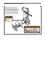
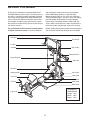
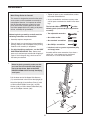
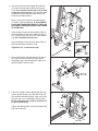
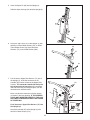
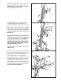
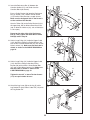
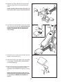
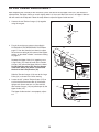
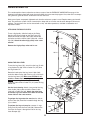
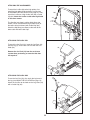
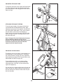
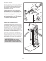
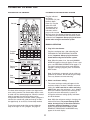
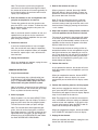
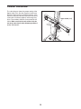
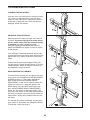
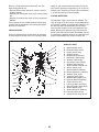
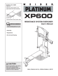
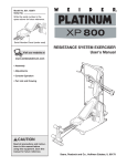
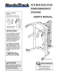
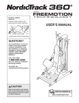
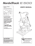
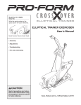
Model No. NTS78740
Serial No.
Write the serial number in the
space above for future reference.
Serial Number Decal (under seat)
QUESTIONS?
USER’S MANUAL
As a manufacturer, we are committed to providing complete
customer satisfaction. If you
have questions, or if there are
missing or damaged parts, we
will guarantee complete satisfaction through direct assistance from our factory.
TO AVOID DELAYS, PLEASE
CALL DIRECT TO OUR TOLLFREE CUSTOMER HOT LINE.
The trained technicians on our
customer hot line will provide
immediate assistance, free of
charge.
CUSTOMER HOT LINE:
1-888-825-2588
Mon.–Fri., 6 a.m.–6 p.m. MST
CAUTION
Read all precautions and instructions in this manual before
using this equipment. Save this
manual for future reference.
Visit our website at
www.nordictrack.com
new products, prizes,
fitness tips, and much more!
TABLE OF CONTENTS
WARNING DECAL PLACEMENT . . . . . . . . . . . . . . . . . . . . . . . . . . . . . . . . . . . . . . . . . . . . . . . . . . . . . . . . . . . . . 3
IMPORTANT PRECAUTIONS . . . . . . . . . . . . . . . . . . . . . . . . . . . . . . . . . . . . . . . . . . . . . . . . . . . . . . . . . . . . . . . . 4
BEFORE YOU BEGIN . . . . . . . . . . . . . . . . . . . . . . . . . . . . . . . . . . . . . . . . . . . . . . . . . . . . . . . . . . . . . . . . . . . . . . 5
ASSEMBLY . . . . . . . . . . . . . . . . . . . . . . . . . . . . . . . . . . . . . . . . . . . . . . . . . . . . . . . . . . . . . . . . . . . . . . . . . . . . . . .6
UPPER CABLE ADJUSTMENT . . . . . . . . . . . . . . . . . . . . . . . . . . . . . . . . . . . . . . . . . . . . . . . . . . . . . . . . . . . . . .12
ADJUSTMENTS . . . . . . . . . . . . . . . . . . . . . . . . . . . . . . . . . . . . . . . . . . . . . . . . . . . . . . . . . . . . . . . . . . . . . . . . . . 13
CONSOLE OPERATION . . . . . . . . . . . . . . . . . . . . . . . . . . . . . . . . . . . . . . . . . . . . . . . . . . . . . . . . . . . . . . . . . . . .17
CABLE DIAGRAM . . . . . . . . . . . . . . . . . . . . . . . . . . . . . . . . . . . . . . . . . . . . . . . . . . . . . . . . . . . . . . . . . . . . . . . . .19
TROUBLESHOOTING . . . . . . . . . . . . . . . . . . . . . . . . . . . . . . . . . . . . . . . . . . . . . . . . . . . . . . . . . . . . . . . . . . . . .20
EXERCISE GUIDELINES . . . . . . . . . . . . . . . . . . . . . . . . . . . . . . . . . . . . . . . . . . . . . . . . . . . . . . . . . . . . . . . . . . 21
ORDERING REPLACEMENT PARTS . . . . . . . . . . . . . . . . . . . . . . . . . . . . . . . . . . . . . . . . . . . . . . . . . .Back Cover
LIMITED WARRANTY . . . . . . . . . . . . . . . . . . . . . . . . . . . . . . . . . . . . . . . . . . . . . . . . . . . . . . . . . . . . . . Back Cover
Note: A PART IDENTIFICATION CHART and a PART LIST/EXPLODED DRAWING are attached in the center of
this manual. Remove the PART IDENTIFICATION CHART and PART LIST/EXPLODED DRAWING before beginning assembly.
NordicTrack is a registered trademark of ICON IP, Inc.
2
WARNING DECAL PLACEMENT
The decals shown here have been
placed on the resistance system. If a
decal is missing or illegible, please call
our Customer Service Department tollfree at 1-888-825-2588, Monday through
Friday, 6 a.m. until 6 p.m. Mountain
Time, to order a free replacement decal.
Apply the decal in the location shown.
Keep hands and
fingers clear of
this area.
3
IMPORTANT PRECAUTIONS
WARNING:
To reduce the risk of serious injury, read the following important precautions
before using the resistance system.
11. Pull on the lower cable only while sitting on
the bench or standing on the base plate. Pull
on the high cables only while sitting on the
bench, with the seat in one of the three positions closest to the upright base, or while
standing on the base plate.
1. Read all instructions in this manual before
using the resistance system. Use the resistance system only as described in this manual.
2. It is the responsibility of the owner to ensure
that all users of the resistance system are
adequately informed of all precautions.
3. The resistance system is intended for home
use only. Do not use the resistance system in
any commercial, rental, or institutional setting.
12. The resistance system is designed to be
used with the included resistance. Do not
use the resistance system with any other
type of resistance.
4. Use the resistance system only on a level
surface. Cover the floor beneath the resistance system to protect the floor.
13. Always disconnect the lat bar from the high
cables when performing an exercise that
does not require it.
5. Make sure that all parts are properly tightened each time the resistance system is
used. Replace any worn parts immediately.
14. Make sure the storage knob is in place and
fully tightened each time the resistance system is used.
6. Keep children under 12 and pets away from
the resistance system at all times.
15. Make sure that the cables remain on the pulleys at all times. If the cables bind as you are
exercising, stop immediately and make sure
that the cables are on the pulleys. Replace all
cables at least every two years.
7. Keep hands and feet away from moving parts.
8. Always wear athletic shoes for foot protection while exercising.
16. Do not pull on the cables while the resistance level is being adjusted.
9. The resistance system is designed to support a maximum user weight of 300 pounds.
17. If you feel pain or dizziness while exercising,
stop immediately and begin cooling down.
10. The crossbar on the top frame is not
designed to be used for pull-up exercises. Do
not hang on the crossbar.
WARNING:
Before beginning this or any exercise program, consult your physician. This
is especially important for persons over the age of 35 or persons with pre-existing health problems.
Read all instructions before using. ICON assumes no responsibility for personal injury or property
damage sustained by or through the use of this product.
4
BEFORE YOU BEGIN
Thank you for selecting the innovative NordicTrack®
FUTURA 2600 resistance system. The resistance system offers a selection of stations designed to develop
every major muscle group of the body. Whether your
goal is to tone your body, build dramatic muscle size
and strength, or improve your cardiovascular system,
the resistance system will help you to achieve the specific results you want.
after reading this manual, please call our Customer
Service Department toll-free at 1-888-825-2588,
Monday through Friday, 6 a.m. until 6 p.m. Mountain
Time (excluding holidays). To help us assist you, please
note the product model number and serial number
before calling. The model number is NTS78740. The
serial number can be found on a decal attached to the
resistance system (see the front cover of this manual).
For your benefit, read this manual carefully before
using the resistance system. If you have questions
Before reading further, please review the drawing below
and familiarize yourself with the parts that are labeled.
Crossbar
Top Frame
Lat Bar
Console
High Pulley
Resistance Bar
Squat Backrest
Squat Pin
Backrest
Storage Knob
Low Pulley
Curl Pad
Row Plate
Seat
Seat Knob
Curl Bar
Base Plate
ASSEMBLED
DIMENSIONS:
Height: 86 in.
Width: 50 in.
Depth: 85 in.
Leg Lever
5
ASSEMBLY
• Tighten all parts as you assemble them, unless
instructed to do otherwise.
Make Things Easier for Yourself
This manual is designed to ensure that the resistance system can be assembled successfully by
most people. However, it is important to realize
that the versatile resistance system has many
parts and that the assembly process will take
time. Most people find that by setting aside plenty
of time, assembly will go smoothly.
• As you assemble the resistance system, make
sure all parts are oriented as shown in the drawings.
The included Allen wrenches
and the
following tools (not included) are required for
assembly:
Before beginning assembly, carefully read the
following information and instructions:
• Two adjustable wrenches
• Assembly requires two persons.
• One standard screwdriver
• One rubber mallet
• Place all parts in a cleared area and remove the
packing materials. Do not dispose of the packing
materials until assembly is completed.
• One Phillips screwdriver
• Lubricant, such as grease or petroleum jelly,
and soapy water.
• For help identifying small parts, use the PART
IDENTIFICATION CHART. Note: Some small
parts may have been pre-attached for shipping. If
a part is not in the parts bag, check to see if it
has been pre-attached.
1.
Assembly will be more convenient if you have a
socket set, a set of open-end or closed-end
wrenches, or a set of ratchet wrenches.
1
Before beginning assembly, make sure that
you have read and understand the information in the box above. Refer to the PART
IDENTIFICATION CHART for help identifying
small parts.
2
Pull the lower end of the Upper Wire Harness
(71) out of the hole in the back of the Upright (2).
71
Attach the Upright (2) to the Base Plate (1) with
an M10 x 25mm Button Screw (88), an M10
Washer (106), an M10 x 92mm Button Bolt (83),
and an M10 Nylon Locknut (103).
88
103
106
83
1
6
2. Insert the connector of the Upper Wire Harness
(71) into the socket of the Lower Wire Harness
(119). The connector should slide easily into the
socket and snap into place. If the connector does
not slide easily and snap into place, turn the connector over and then insert it.
2
Make sure that the connector and wires appear
as shown in the inset drawing. IF THE CONNECTOR IS NOT INSERTED PROPERLY, THE CONSOLE MAY BE DAMAGED WHEN THE POWER
IS TURNED ON.
85
12
6
119
71
Insert the Mech Frame (6) into the Base Plate (1).
Attach the Mech Frame to the Upright (2) with a
1/2” x 25mm Screw (85) and a 1/2” Lock Washer
(12). Do not tighten the Screw yet.
103
Attach the Mech Frame (6) to the Base Plate (1)
with four M10 Nylon Locknuts (103).
2
1
Black
Wire
Tighten the 1/2” x 25mm Screw (85).
119
103
Red
Wire
71
3. Press the Rail Cap (49) onto the Leg (5). Attach
the Leg to the Rail (4) with two M10 x 64mm
Button Bolts (80), four M10 Washers (106), and
two M10 Nylon Locknuts (103).
3
103
106
4
Holes on
this side
106
49
80
5
4. Lubricate an M10 x 125mm Button Bolt (89) with
grease. Attach the Rail (4) to the Row Plate (28)
with the Bolt, two M10 Washers (106), two 31mm
Spacers (30), and an M10 Nylon Locknut (103).
Do not overtighten the Locknut; the Rail must
be able to pivot easily.
4
29
28
103 106
Tighten the Storage Knob (29) into the Row Plate
(28) and the Rail (4).
30
4
30
106
Lubricate
7
89
5. Insert the Squat Pin (66) into the Upright (2).
5
Slide the Squat Carriage (19) onto the Upright (2).
2
19
66
6. Attach the Top Frame (37) to the Upright (2) with
two M10 x 25mm Button Screws (88), an M10 x
75mm Button Screw (84), three M10 Lock
Washers (75), and an M10 Washer (106).
6
88
37
75
84
2
106
7. Pull the excess Upper Wire Harness (71) out of
the Upright (2). Insert the connector on the
Console (67) into the socket on the Upper Wire
Harness. The connector should slide easily into
the socket and snap into place. If the connector
does not slide easily and snap into place, turn the
connector over and then insert it.
75
7
114
71
2
67
Make sure that the connector and wires appear
as shown in the inset drawing. IF THE CONNECTOR IS NOT INSERTED PROPERLY, THE CONSOLE MAY BE DAMAGED WHEN THE POWER
IS TURNED ON.
114
Black
Wire
Push the excess Upper Wire Harness (71) into
the Upright (2).
71
Attach the Console (67) to the Upright (2) with
four M4 x 70mm Screws (114).
67
8
Red
Wire
8. Attach a Large Pulley (14) and the Pulley Plate
(68) to the Upright (2) with an M12 x 62mm
Button Bolt (81) and an M12 Nylon Locknut (13).
Do not tighten the Locknut yet.
8
68
13
14
2
81
9. Pull the Upper Cable (121), which is attached
inside of the Mech Frame (not shown), up
between the Upright (2) and the Pulley Plate (68).
9
Attach another Large Pulley (14) to the Upright (2)
and Pulley Plate (68) with an M12 x 62mm Button
Bolt (81) and an M12 Nylon Locknut (13). Make
sure that the Upper Cable (121) is between the
two Pulleys.
11
90
121
13
68
81
Hold the 38mm Spacer (90) inside the loop of the
Upper Cable (121), and between the Upright (2)
and the Pulley Plate (68). Attach the Spacer with
an M10 x 58mm Button Screw (11). Make sure
the ends of the Cable do not wrap around
each other below the Spacer and the Large
Pulleys (14) used in steps 8 and 9 (refer to the
CABLE DIAGRAM on page 19).
14
2
Tighten the M12 Nylon Locknuts (13) used in
steps 8 and 9.
10. Attach a Small Guide Spacer (18), a Large Guide
Spacer (17), and two Crossbar Guides (15) to the
Upright (2) with an M10 x 152mm Bolt (86).
10
Pull the Upper Cable (121) up between the
Crossbar Guides (15). Press the metal cover on
the Cable into the groove in the Crossbar Block
(16). Attach a Small Guide Spacer (18), the
Crossbar Block, the two Crossbar Guides (15), an
M10 Thick Washer (54), and the two Tethers (70)
to the Upright (2) with another M10 x 152mm Bolt
(86). Do not tighten the Bolt yet.
17
18
86
15
2
121
Metal
Cover
54
86
70
18
9
16
Groove
11. Insert the Resistance Bar (9) between the
Crossbar Guides (15), and center it on the
Crossbar Block (not shown).
11
15
Press a Pulley Bracket (10) onto the Resistance
Bar (9). Screw a 3/8” x 38mm Tension Screw
(117) into the Pulley Bracket a couple of turns.
Make sure the hexagonal hole in the Screw is
on the outside of the Bracket.
70
54
9
Attach a Tether (70) to the Pulley Bracket (10) at
the upper hole, with an M10 x 64mm Button Bolt
(80), an M10 Thick Washer (54), and an M10 Nylon
Locknut (103).
103
10
80
117
Repeat on the other side of the Resistance
Bar (9). Then, tighten the lower M10 x 152mm
Bolt (86) used in step 10.
12
13
12. Hold a Large Pulley (14) inside the Upper Cable
(121). Attach the Pulley to a Pulley Bracket (10)
with an M12 x 58mm Button Bolt (87) and an M12
Nylon Locknut (13). Make sure that the Cable is
routed as shown in the CABLE DIAGRAM on
page 19.
10
87
14
121
13. Hold a Large Pulley (14) inside the Upper Cable
(121). Attach the Pulley to the other Pulley
Bracket (10) with an M12 x 58mm Button Bolt
(87) and an M12 Nylon Locknut (13). Make sure
that the Cable is routed as shown in the
CABLE DIAGRAM on page 19.
13
13
Tighten the two 3/8” x 38mm Tension Screws
(117) an equal number of turns.
117
121
10
87
14. Attach the Leg Lever (56) to the Leg (5) with a
Leg Station Pin (60). Slide a Cotter Pin (113) onto
the Leg Station Pin.
14
14
5
56
113
60
10
15. Slide the Pad Tube (50) into the Leg Lever (56).
Slide two Large Foam Pads (52) onto the Pad
Tube.
15
5
Attach the other two Pad Tubes (50) to the Leg
Lever (56) and the Leg (5) in the same manner.
50
56
52
50
52
50
16. Insert the rod on the Backrest Frame (32) into the
slot in the Seat Carriage (44). Hold the Backrest
Frame vertically over the Seat Carriage and
slide the rod into the slot, as shown in the
inset drawing.
16
32
Rod
Slot
44
32
44
17. Attach the Curl Pad (43) to the Curl Post (42) with
two M6 x 16mm Screws (41).
17
43
18. Adjust the tension on the upper cable (not shown)
as described in UPPER CABLE ADJUSTMENT
on the following page.
19. Make sure that all parts have been properly tightened. The use of the remaining parts will be
explained in ADJUSTMENTS, beginning on page
13.
42
Before using the resistance system, turn on
the console and change the resistance setting
as described in CONSOLE OPERATION on
page 17.
41
11
UPPER CABLE ADJUSTMENT
After completing the assembly of the resistance system, the tension on the Upper Cable (121) will need to be
adjusted. Also, the Upper Cable can stretch slightly when it is first used. When this occurs, the Upper Cable tension will need to be readjusted. Follow the steps below to adjust the Upper Cable tension.
1. Connect the two Tension Gauges (118) together
using the magnet.
1
118
Magnet
118
2. Plug in the resistance system as described in
PLUGGING IN THE RESISTANCE SYSTEM on
page 17. Use the Console (not shown) to adjust
the resistance setting of the system to the highest
setting, as described in Select a resistance setting
on page 17.
2
10
118
121
Squeeze the Upper Cable (121) together near a
Large Pulley (14). Hook the ends of the Tension
Gauges (118) around the Upper Cable as shown.
Do not hook the ends of the Tension Gauges
around the Tether (70); which is attached to
the back of the Pulley Bracket (10).
118
14
70
121
Slide the Tension Gauges (118) next to the Large
Pulley (14) as shown in the inset drawing.
118
14
3. Locate the 3/8” x 38mm Tension Screw (117) on
each end of the Resistance Bar (9). Alternately
tighten each Screw one turn at a time until the
two Tension Gauges (118) are pulled apart by the
Upper Cable (121).
3
9
117
The Upper Cable tension is now properly adjusted.
118
118
121
12
118 121
ADJUSTMENTS
This section explains how to adjust the resistance system. See the EXERCISE GUIDELINES on page 21 for
important information about how to get the most benefit from your exercise program. Also, refer to the accompanying exercise guide to see the correct form for each exercise.
Make sure all parts are properly tightened each time the resistance system is used. Replace worn parts immediately. The resistance system can be cleaned with a damp cloth and a mild, non-abrasive detergent. Do not use
solvents. The resistance bar can be cleaned with a vinyl and rubber protectant, available at automotive and
department stores.
ATTACHING THE HIGH PULLEYS
37
To use a high pulley, slide the hook on the Pulley
Housing (39) onto an hook on the Top Frame (37).
Attach the end of the High Cable (101) without the
ball to the end of the Lower Cable (120) with a Cable
Clip (94). Attach the other high pulley in the same
manner.
39
Ball
Remove the high pulleys when not in use.
101
USING THE LEG LEVER
To use the Leg Lever (56), attach it to the Leg (5) with
a Leg Station Pin (60). Slide a Cotter Pin (113) onto
the Leg Station Pin.
120
Route the hook end of the Leg Lever Cable (102)
under the 90mm Pulley (40) in the Leg (5), and attach
it to the Leg Lever (56). Make sure the hook is oriented as shown when attaching it to the Leg
Lever. Insert a Leg Station Pin (60) into the Leg,
under the Cable. Slide a Cotter Pin (113) onto the Leg
Station Pin.
94
50
56
52
113
55
See the inset drawing. Attach a long end of the Leg
Lever Cable (102) to one end of the Lower Cable
(120) with a Cable Clip (94). Attach the other long
end of the Leg Lever Cable to the other end of the
Lower Cable in the same manner.
5
40
102
113
To perform the leg extension exercise, the indicated Pad Tube (50) should be inserted through the Leg
(5) as shown.
60
Hook
To perform the leg curl exercise, remove a Large
Foam Pad (52) from the Pad Tube (50). Remove the
Pad Tube and insert it through the hole in the Leg
Lever Bumper (55).
102
94
120
13
60
ATTACHING THE ACCESSORIES
To attach the Lat Bar (82) to the high pulleys, first
attach the high pulley to the resistance system (see
ATTACHING THE HIGH PULLEYS on page 13). Then,
attach the Lat Bar to a High Cable (101) with a Cable
Clip (94). Attach the Lat Bar to the other High Cable
in the same manner.
101
94
101
The Handles (not shown) and the Ankle Strap (not
shown) can be attached to the High Cables (101) or
the lower cable (not shown) with Cable Clips (94).
Attach the Hip Strap (not shown) to the ends of the
lower cable with two Cable Clips.
82
ATTACHING THE CURL PAD
To attach the Curl Pad (43), insert the Curl Post (42)
into the Leg (5). Secure the Curl Post with the Curl
Knob (59).
43
Remove the Curl Pad (43) from the resistance
system when performing an exercise that does
not require it.
42
5
ATTACHING THE CURL BAR
To use the Curl Bar (53), first attach the leg lever to
the leg (see USING THE LEG LEVER on page 13).
Attach the Curl Bar to the hook on the Leg Lever (56)
with a Cable Clip (94).
53
94
56
14
59
ADJUSTING THE SQUAT ARM
27
To adjust the Squat Arm (20), remove the Squat Knob
(27) from Squat Carriage (19). Move the Arm to the
up or down position, and reengage the Knob into the
Squat Carriage.
19
20
ATTACHING THE SQUAT STATION
To use the squat station, first remove the backrest
(see ADJUSTING THE BACKREST below). Next,
adjust the squat arm to the up position (see ADJUSTING THE SQUAT ARM above). Then, insert a Squat
Pin (66) into the correct hole in the Upright (2).
Finally, attach each end of the lower cable (B) to the
Squat Carriage (19) with a Carriage Strap (77) and
two Cable Clips (94).
20
94
Note: The Squat Pin (66) will determine the lowest
point to which the Squat Carriage (19) can
descend. The Squat Carriage should not be able to
descend so low that the user could become
trapped under the Squat Arm (20).
19
2
77
66
94
B
ADJUSTING THE BACKREST
35
The Backrest (35) can be used in a level position or an
inclined position. To use the Backrest in a level position, secure the Seat Carriage (44) at the adjustment
hole in the Rail (4) closest to the Leg (not shown) (see
ADJUSTING THE SEAT on page 16).
2
To use the Backrest (35) in an inclined position,
secure the Seat Carriage (44) at one of the other
adjustment holes in the Rail (4). Rest the Backrest
against the Upright (2).
For row exercises, remove the Backrest (35) from the
Seat Carriage (44). Hold the Backrest vertically over
the Seat Carriage and lift the rod out of the slot (see
the inset drawing).
4
Rod
32
44
Slot
44
15
ADJUSTING THE SEAT
45
The Seat (45) can be secured at various positions on
the Rail (4). To move the Seat, pull the Seat Knob
(48) out as far as it will go and slide the Seat to the
desired position. Engage the Seat Knob into an
adjustment hole in the Rail.
35
4
To perform row exercises, the hip strap must be
attached to the mech cable (see ATTACHING THE
ACCESSORIES, on page 14), and the Seat Carriage
(44) must be able to roll along the Rail (4). First,
remove the Backrest (35) from the Seat Carriage (see
ADJUSTING THE BACKREST on page 15). Then,
pull the Seat Knob (48) out as far as it will go, and
turn the Knob so that the pin rests at the end of the
“L”-shaped slot (see the inset drawing).
44
48
Adjustment
Hole
Pin
44
“L”-Slot
48
STORING THE RESISTANCE SYSTEM
37
To store the resistance system, first remove the Curl
Pad (not shown) and the Leg Lever (not shown) from
the resistance system. Secure the Seat Carriage (44)
at the position closest to the Leg (5) (see ADJUSTING
THE SEAT above). Next, remove the Storage Knob
(29) from the Row Plate (28). Lift the Leg toward the
Top Frame (37), and tighten the Storage Knob into the
side of the Row Plate and into the Rail (4).
Hold in
this area
5
44
To move the resistance system, stand behind the
Upright (2) and place the toe of your shoe on the end
of the Base Plate (1) and hold the resistance system
in the indicated area. Tilt the resistance system back
onto the Wheels (65) and roll it to the new location.
2
WARNING:
Make sure that
Storage Knob (29) is in place and fully tightened each time the resistance system is used.
4
28
65
29
1
16
CONSOLE OPERATION
FEATURES OF THE CONSOLE
Console
PLUGGING IN THE RESISTANCE SYSTEM
Plug the indicated
end of the
Transformer (72) into
the Back Mech
Cover (8). Plug the
other end of the
Transformer into a
8
120-volt outlet. All
72
indicators and displays on the console
will flash once; the console will then be ready for use.
The motor may be heard while the resistance system
calibrates itself. Important: Always plug in the transformer when using the resistance system.
MANUAL OPERATION
1. Plug in the transformer.
Program
Buttons
Plug the transformer into a 120-volt outlet (see
PLUGGING IN THE RESISTANCE SYSTEM
above). Important: Always plug in the transformer when using the resistance system.
Main
Display
Note: When the power is on, the words MANUAL
MODE will appear in the main display. To use a program, see PROGRAM OPERATION on page 18. If
you want to return to the manual mode while the
console is running a program, press and hold the
NEXT button.
Resistance
Display
Note: If no buttons are pressed and no cables are
pulled for ten minutes, the console will go to sleep.
Press any button to resume exercising.
Sets
Display
Reps
Display
2. Select a resistance setting.
The current resistance setting will appear in the
resistance display. To select a different resistance
setting, first make sure that no cables are being
pulled. Next, press the resistance + and – buttons.
Each time a button is pressed, the resistance setting will increase or decrease by 1 pound. To
change the resistance setting quickly, hold down
one of the buttons.
The heart of the resistance system is the digital resistance training console. The console offers both a manual mode and nine workout programs. When the manual
mode is selected, the resistance setting can be
changed with the touch of a button. When a program is
selected, the console will guide you through an effective upper body, ab and back, or lower body workout.
Note: While the resistance setting is changing, the
motor will be heard. To prevent damage to the
motor, do not pull any of the cables while the
resistance setting is changing. If a cable is
pulled, the words RELEASE HANDLES AND
READJUST RESISTANCE AS DESIRED may
appear in the main display.
To use the manual mode of the console, follow the
steps at the right. To use a program, see page 18.
17
Note: The resistance system uses progressive
resistance. As the resistance bar begins to bend,
the amount of resistance will increase gradually. As
the bar bends further, the resistance will increase
rapidly, up to 340 pounds.
3. Row for five minutes to warm up.
When a program is selected, the words CARDIO
ROW will appear in the main display. To warm up,
perform the cardio row exercise while the main display counts down from 5 minutes.
3. Enter the numbers of sets and repetitions that
you plan to complete for an exercise.
Note: To see the correct form for the cardio row
exercise, see the included exercise guide. If the
resistance setting is too high or too low, select a different resistance setting by pressing the resistance
+ and – buttons.
To enter the number of sets that you plan to do,
press the SETS + and – buttons. To enter the number of repetitions that you plan to do, press the
REPS + and – buttons.
Note: If you do not enter the numbers of sets and
repetitions that you plan to do, the console will
count the total number of repetitions that you complete during your workout.
4. Adjust the resistance setting and the numbers of
sets and repetitions for the exercise if desired.
The name of an exercise in the program will appear
in the main display. The recommended resistance
setting and the recommended numbers of sets and
repetitions for the exercise will appear in the three
displays below the main display.
4. Perform the exercise.
If you have entered numbers of sets and repetitions, the console will count down the repetitions
and sets you have completed. When you complete
the exercise, repeat steps 2 and 3 above for the
next exercises.
The recommended resistance setting and the recommended numbers of sets and repetitions may be
too high or too low for you, depending on such factors as your body size and your physical condition. If
desired, adjust the resistance setting and the numbers of sets and repetitions by pressing the + and –
buttons below each display.
5. Unplug the transformer.
When you complete your workout, unplug the transformer from the 120-volt outlet.
5. Perform the exercise.
As you perform the exercise, the console will count
down the numbers of sets and repetitions you have
completed.
PROGRAM OPERATION
1. Plug in the transformer.
When you complete the exercise, the word RESTING will appear in the main display. It is recommended that you rest while the main display counts
down.
Plug the transformer into a 120-volt outlet (see
PLUGGING IN THE RESISTANCE SYSTEM on
page 17). Important: Always plug in the transformer when using the resistance system.
6. Perform the remaining exercises in the program.
Note: If no buttons are pressed and no cables are
pulled for ten minutes, the console will go to sleep.
Press any button to resume exercising.
After you have completed an exercise in the program, press the NEXT button and the name of the
next exercise will appear in the main display. Repeat
steps 4 and 5 above for the exercise.
2. Select a program.
Note: The program may include the same exercise
twice, with different resistance settings and different
numbers of sets and repetitions. If you wish to skip
any part of the program, press the NEXT button to
advance to the next part of the program.
When the power is on, the words SELECT PROGRAM will appear in the main display. To select a
program, press one of the nine program buttons.
The indicator on the button you press will light.
Note: The console offers three upper body programs, three ab and back programs, and three
lower body programs. If you wish to exercise your
upper body and if your goal is to lose weight, for
example, press the LOSE WEIGHT button below
the words UPPER BODY PROGRAMS.
When you complete the program, the words WORKOUT COMPLETE will appear in the main display.
7. Unplug the transformer.
When you complete your workout, unplug the transformer from the 120-volt outlet.
18
CABLE DIAGRAM
The cable diagram shows the proper routing of the
Upper Cable (121). Use the diagram to make sure
that the Cable has been assembled correctly. If the
Cable has not been correctly routed, the resistance
system will not function properly and damage may
occur. The numbers show the correct route for the
Cable. Make sure that the ends of the Cable do
not wrap around each other between positions 1
and 2, and 6 and 7.
Upper Cable (121)
5
4
6
2
1
7
19
3
TROUBLESHOOTING
CLEANING THE BAR GUIDES
Over time, dust may build up on the Crossbar Guides
(15), causing a squeaking noise as the resistance
system is used. If this occurs, wipe off the Crossbar
Guides with a damp cloth and a mild, non-abrasive
detergent. Do not use solvents.
15
ADJUSTING THE RESISTANCE
When the resistance setting changes, the motor will
be heard. To prevent damage to the motor, do not
pull any of the cables while the resistance setting
is changing. If a cable is pulled, the words
RELEASE HANDLES AND READJUST RESISTANCE AS DESIRED may appear in the main display
on the console.
If this message is displayed repeatedly but no cable
is being pulled, there may be too much tension on the
Upper Cable (121). Adjust the tension as described
below.
To decrease the tension on the Upper Cable (121),
turn the two 3/8” x 38mm Tension Screws (117) twice,
counterclockwise. Select the desired resistance setting. Repeat this step if necessary.
121
RECALIBRATING THE CONSOLE
To recalibrate the Console (67), first plug in the resistance system (see PLUGGING IN THE RESISTANCE
SYSTEM on page 17). Then, press and hold the
NEXT button and the MOTORIZED WEIGHT
ADJUSTMENT + button for five seconds. When the
buttons are released, a number will appear in the
REPS display. Press the NEXT button again, then
press the MOTORIZED WEIGHT ADJUSTMENT +
button; this will start the recalibration process. This
may take a few minutes as the motor moves between
the lowest and highest resistance settings. When the
motor finishes, unplug the transformer from the 120volt outlet.
67
The Console (67) will be recalibrated. Use the resistance system as described in the CONSOLE OPERATION section, starting on page 17.
20
117
EXERCISE GUIDELINES
THE FOUR BASIC TYPES OF WORKOUTS
PERSONALIZING YOUR EXERCISE PROGRAM
Muscle Building
To increase the size and strength of your muscles,
push them close to their maximum capacity. Your muscles will continually adapt and grow as you progressively increase the intensity of your exercise. You can
adjust the intensity level of an individual exercise in
two ways:
• by changing the amount of resistance used
• by changing the number of repetitions or sets performed. (A “repetition” is one complete cycle of an
exercise, such as one sit-up. A “set” is a series of
repetitions.)
Determining the exact length of time for each workout,
as well as the number of repetitions or sets completed,
is an individual matter. It is important to avoid overdoing it during the first few months of your exercise program. You should progress at your own pace and be
sensitive to your body’s signals. If you experience pain
or dizziness at any time while exercising, stop immediately and begin cooling down. Find out what is wrong
before continuing. Remember that adequate rest and a
proper diet are important factors in any exercise program.
WARMING UP
The proper amount of resistance for each exercise
depends upon the individual user. You must gauge
your limits and select the amount of resistance that is
right for you. Begin with 3 sets of 8 repetitions for each
exercise you perform. Rest for 3 minutes after each
set. When you can complete 3 sets of 12 repetitions
without difficulty, increase the amount of resistance.
Begin each workout with 5 to 10 minutes of stretching
and light exercise to warm up. Warming up prepares
your body for more strenuous exercise by increasing
circulation, raising your body temperature and delivering more oxygen to your muscles.
WORKING OUT
Toning
You can tone your muscles by pushing them to a moderate percentage of their capacity. Select a moderate
amount of resistance and increase the number of repetitions in each set. Complete as many sets of 15 to
20 repetitions as possible without discomfort. Rest for
1 minute after each set. Work your muscles by completing more sets rather than by using high amounts of
resistance.
Each workout should include 6 to 10 different exercises. Select exercises for every major muscle group,
emphasizing areas that you want to develop most. To
give balance and variety to your workouts, vary the
exercises from session to session.
Schedule your workouts for the time of day when your
energy level is the highest. Each workout should be
followed by at least one day of rest. Once you find the
schedule that is right for you, stick with it.
Weight Loss
To lose weight, use a low amount of resistance and
increase the number of repetitions in each set.
Exercise for 20 to 30 minutes, resting for a maximum
of 30 seconds between sets.
EXERCISE FORM
Cross Training
Cross training is an efficient way to get a complete and
well-balanced fitness program. An example of a balanced program is:
• Plan strength training workouts on Monday,
Wednesday, and Friday.
• Plan 20 to 30 minutes of aerobic exercise, such as
running on a treadmill or riding on an elliptical or
exercise bike, on Tuesday and Thursday.
• Rest from both strength training and aerobic exercise
for at least one full day each week to give your body
time to regenerate.
The combination of strength training and aerobic exercise will reshape and strengthen your body, plus develop your heart and lungs.
Maintaining proper form is an essential part of an
effective exercise program. This requires moving
through the full range of motion for each exercise, and
moving only the appropriate parts of the body.
Exercising in an uncontrolled manner will leave you
feeling exhausted. On the exercise guide accompanying this manual you will find photographs showing the
correct form for several exercises, and a list of the
muscles affected. Refer to the muscle chart on the
next page to find the names of the muscles.
The repetitions in each set should be performed
smoothly and without pausing. The exertion stage of
each repetition should last about half as long as the
return stage. Proper breathing is important. Exhale
during the exertion stage of each repetition and inhale
during the return stroke. Never hold your breath.
21
slowly as you stretch and do not bounce. Ease into
each stretch gradually and go only as far as you can
without strain. Stretching at the end of each workout
is an effective way to increase flexibility.
Rest for a short period of time after each set. The
ideal resting periods are:
• Rest for three minutes after each set for a muscle
building workout.
• Rest for one minute after each set for a toning workout.
• Rest for 30 seconds after each set for a weight loss
workout.
Plan to spend the first couple of weeks familiarizing
yourself with the equipment and learning the proper
form for each exercise.
STAYING MOTIVATED
For motivation, keep a record of each workout. The
chart on page 23 of this manual can be photocopied
and used to schedule and record your workouts. List
the date, the exercises performed, the resistance
used, and the numbers of sets and repetitions completed. Record your weight and key body measurements at the end of every month. Remember, the key
to achieving the greatest results is to make exercise a
regular and enjoyable part of your everyday life.
COOLING DOWN
End each workout with 5 to 10 minutes of stretching.
Include stretches for both your arms and legs. Move
MUSCLE CHART
O
A
P
L
B
Q
C
R
D
S
E
T
F
G
M
U
N
H
V
I
W
J
X
K
22
A.
B.
C.
D.
E.
F.
G.
H.
I.
J.
K.
L.
M.
N.
O.
P.
Q.
R.
S.
T.
U.
V.
W.
X.
Sternomastoid (neck)
Pectoralis Major (chest)
Biceps (front of arm)
Obliques (waist)
Brachioradials (forearm)
Hip Flexors (upper thigh)
Abductor (outer thigh)
Quadriceps (front of thigh)
Sartorius (front of thigh)
Tibialis Anterior (front of calf)
Soleus (front of calf)
Anterior Deltoid (shoulder)
Rectus Abdominus (stomach)
Adductor (inner thigh)
Trapezius (upper back)
Rhomboideus (upper back)
Posterior Deltoid (shoulder)
Triceps (back of arm)
Latissimus Dorsi (mid back)
Spinae Erectors (lower back)
Gluteus Medius (hip)
Gluteus Maximus (buttocks)
Hamstring (back of leg)
Gastrocnemius (back of calf)
EXERCISE
MONDAY
WEIGHT
SETS
REPS
WEIGHT
SETS
REPS
WEIGHT
SETS
REPS
Date:
/
/
AEROBIC EXERCISE
TUESDAY
Date:
/
/
WEDNESDAY
EXERCISE
Date:
/
/
THURSDAY
AEROBIC EXERCISE
Date:
/
/
EXERCISE
FRIDAY
Date:
/
/
Make photocopies of this page for scheduling and recording your workouts.
23
PART LIST—Model No. NTS78740
Key No. Qty.
1
2
3
4
5
6
7
8
9
10
11
1
1
1
1
1
1
1
1
1
2
1
12
13
1
4
14
15
16
17
4
2
1
1
18
2
19
20
21
22
23
24
25
26
27
28
29
30
31
32
33
34
1
2
6
1
2
2
1
8
1
1
1
2
1
1
1
2
35
36
37
38
1
3
1
2
39
40
41
42
43
44
45
46
47
48
49
50
51
2
5
10
1
1
1
1
1
1
1
1
3
6
52
53
6
1
Description
Base Plate
Upright
Upright Cover
Rail
Leg
Mech Frame
Front Mech Cover
Back Mech Cover
Resistance Bar
Pulley Bracket
M10 x 58mm
Button Screw
1/2” Lock Washer
M12 Nylon
Locknut
Large Pulley
Crossbar Guide
Crossbar Block
Large Guide
Spacer
Small Guide
Spacer
Squat Carriage
Squat Arm
Short Handgrip
Squat Pivot Tube
Squat Arm Roll Pin
Small Foam Pad
Squat Backrest
Carriage Wheel
Squat Knob
Row Plate
Storage Knob
31mm Spacer
Rail Insert
Backrest Frame
Backrest Cap
25mm Square
Inner Cap
Backrest
Plastic Foot
Top Frame
38mm Round
Inner Cap
Pulley Housing
90mm Pulley
M6 x 16mm Screw
Curl Post
Curl Pad
Seat Carriage
Seat
Pop Pin
Knob Spring
Seat Knob
Rail Cap
Pad Tube
19mm Round
Inner Cap
Large Foam Pad
Curl Bar
Key No. Qty.
54
55
56
57
58
3
1
1
2
1
59
60
61
62
63
64
65
66
67
68
69
70
71
1
2
2
2
1
2
2
1
1
1
1
2
1
72
73
1
2
74
2
75
76
77
78
3
1
2
4
79
80
4
6
81
2
82
83
1
1
84
5
85
1
86
87
2
2
88
3
89
1
90
91
92
1
1
1
93
4
94
95
96
97
98
4
2
2
1
1
Description
M10 Thick Washer
Leg Lever Bumper
Leg Lever
Leg Lever Bushing
Leg Station
Bushing
Curl Knob
Leg Station Pin
22mm Spacer
Leg Outer Cap
Base Plate Foot
Wheel Insert
Wheel
Squat Pin
Console
Pulley Plate
Cable Guide
Tether
Upper Wire
Harness
Transformer
Pulley Pivot
Bracket
Pivot Bracket
Bushing
M10 Lock Washer
M5 x 35mm Screw
Carriage Strap
M10 x 40mm
Button Bolt
16mm Spacer
M10 x 64mm
Button Bolt
M12 x 62mm
Button Bolt
Lat Bar
M10 x 92mm
Button Bolt
M10 x 75mm
Button Bolt
1/2” x 25mm
Screw
M10 x 152mm Bolt
M12 x 58mm
Button Bolt
M10 x 25mm
Button Screw
M10 x 125mm
Button Bolt
38mm Spacer
Reed Sensor
M10 x 85mm
Button Bolt
M10 x 44mm
Button Bolt
Cable Clip
Long Handle
Short Handle
Hip Strap
Ankle Strap
R0304A
Key No. Qty.
99
2
100
101
102
103
2
2
1
33
104
4
105
106
107
108
109
4
14
4
2
2
110
1
111
112
4
2
113
114
115
116
117
2
4
4
9
2
118
119
120
121
122
123
124
125
126
127
128
129
130
131
132
133
134
135
1
1
1
1
8
2
2
1
2
2
1
2
1
2
2
1
1
2
136
137
138
139
140
141
142
4
1
2
4
1
2
4
#
#
#
#
#
1
1
1
1
1
Description
M10 x 78mm
Button Bolt
M4 x 38mm Screw
High Cable
Leg Lever Cable
M10 Nylon
Locknut
M10 x 34mm
Button Bolt
M6 x 38mm Screw
M10 Washer
M6 Washer
M5 x 56mm Screw
M4 x 7mm
Machine Screw
45mm Square
Inner Cap
M4 x 20mm Screw
M4 x 5mm Screw
(Round Head)
Cotter Pin
M4 x 70mm Screw
11mm Spacer
M4 x 16mm Screw
3/8" x 38mm
Tension Screw
Tension Gauge Kit
Low Wire Harness
Lower Cable
Upper Cable
Large Mech Pulley
Small Mech Pulley
Plate Pulley
Lead Screw Assm.
Mech Cap
6mm Spacer
Plate Pulley Spacer
M10 Mech Washer
Mech Cotter Pin
Limit Switch
M10 x 89mm Bolt
M10 x 95mm Bolt
M10 x 102mm Bolt
M10 x 16mm
Button Screw
M3 x 19mm Screw
M10 x 122mm Bolt
Clevis Pin
M3 Nut
M10 x 44mm Bolt
Spacer Magnet
Mech M10 Nylon
Locknut
User’s Manual
Exercise Guide
Video
Large Allen Wrench
Small Allen Wrench
Note: “#” indicates a non-illustrated part. Specifications are subject to change without notice. See the back cover
of the user’s manual for information about ordering replacement parts.
REMOVE THIS PART IDENTIFICATION CHART AND PART LIST/
EXPLODED DRAWING. SAVE THIS PART IDENTIFICATION CHART
AND PART LIST/EXPLODED DRAWING FOR FUTURE REFERENCE.
PART IDENTIFICATION CHART—Model No. WESY78740
M10 x 58mm Button Screw (11)
M10 x 25mm Button Screw (88)
1/2" x 25mm Screw (85)
M12 x 58mm Button Bolt (87)
38mm Spacer (90)
3/8" x 38mm Tension Screw (117)
M12 x 62mm Button Bolt (81)
31mm Spacer (30)
M12 Nylon Locknut (13)
M10 x 64mm Button Bolt (80)
M4 x 70mm Screw (114)
1/2" Lock Washer (12)
M10 Nylon Locknut (103)
M10 x 75mm Button Bolt (84)
M10 x 85mm Button Bolt (92)
M10 Thick Washer (54)
M10 Washer (106)
M10 x 92mm Button Bolt (83)
M10 Lock Washer (75)
M10 x 125mm Button Bolt (89)
M10 x 152mm Bolt (86)
53
21
52
56
50
51
42
43
51
40
62
57
50
51
51
104
106
102
61
55
103
21
41
21
40
103
103
1
99
36
64
116
106
106
103
64
103
65
103
77
106
103
62
60
100
92
103
116
100
80
106
4
34
105
32
107
65
81
3
103
30
110
106
103
106
67
80
99
116
107
31
36 105
116
116
33
5
61
106 113
63
49
106
106
48
21
103
39
38
75
35
36
113
108
102
106
26
115
104
26
44 103
47
103
40
93
101
75
104
46
115
37
60
58
52
41
45
82
103
41
59
103
93
39
26 104
115
101
103
38
88
83
106
89
28
66
2
14
84
120
84
70
93
11
103
78
73
124
128
141
142
109
41
26
79
6
142
74
136
26
78
103
41
12
142
122
23
111
9
21
24
140
112
40
74
18
120
103
73
131
76
139
91
14
10
135
136
54
71
103
70
119
118
72
117
13
95
86
96
98
129
125
127
126
138
135 127
129
121
126
130
94
70
86
15
54
87
80
16
116
111
15
17
97
111
137
132
93
8
18
85 132
122
142
103
134
133
123
109
69
79 103
78
20
79
13
7
111
14
10
26
19
78
103
27
40 103 112
122 103
68
131
13
75
139
90
23
22
117
80
87
103
25
20
114
54
114
106
106
88
29
21
24
EXPLODED DRAWING—Model No. NTS78740
R0304A
ORDERING REPLACEMENT PARTS
To order replacement parts, simply call our Customer Service Department toll-free at 1-888-825-2588, Monday
through Friday, 6 a.m. until 6 p.m. Mountain Time (excluding holidays). To help us assist you, please be prepared to give the following information:
• The MODEL NUMBER of the product (NTS78740)
• The NAME of the product (NordicTrack® FUTURA 2600 resistance system)
• The SERIAL NUMBER of the product (see the front cover of this manual)
• The KEY NUMBER and DESCRIPTION of the part(s) (see the PART LIST and EXPLODED DRAWING in the
center of this manual)
LIMITED WARRANTY
WHAT IS COVERED—The entire NordicTrack® FUTURA 2600 resistance system (“Product”) is warranted to be free of all defects
in material and workmanship.
WHO IS COVERED—The original purchaser or any person receiving the Product as a gift from the original purchaser.
HOW LONG IS IT COVERED—ICON Health & Fitness, Inc. (“ICON”), warrants the resistance bar for the lifetime of the product.
ICON warrants all other parts for ten years after the date of purchase.
WHAT WE DO TO CORRECT COVERED DEFECTS—We will ship to you, without charge, any replacement part or component, providing the repairs are authorized by ICON first and are performed by an ICON trained and authorized service provider, or, at our
option, we will replace the Product.
WHAT IS NOT COVERED—Any failures or damage caused by unauthorized service, misuse, accident, negligence, improper
assembly or installation, alterations, modifications without our written authorization or by failure on your part to use, operate, and
maintain as set out in your User’s Manual (“Manual”).
WHAT YOU MUST DO—Always retain proof of purchase, such as your bill of sale; store, operate, and maintain the Product as specified in the Manual; notify our Customer Service Department of any defect within 10 days after discovery of the defect; as instructed, return any defected part for replacement or, if necessary, the entire product, for repair.
USER’S MANUAL—It is VERY IMPORTANT THAT YOU READ THE MANUAL before operating the Product. Remember to do the
periodic maintenance requirements specified in the Manual to assure proper operation and your continued satisfaction.
HOW TO GET PARTS AND SERVICE—Simply call our Customer Service Department at 1-888-825-2588 and tell them your name
and address and the serial number of your Product. They will tell you how to get a part replaced, or if necessary, arrange for service where your Product is located or advise you how to ship the Product for service. Before shipping, always obtain a Return
Authorization Number (RA No.) from our Customer Service Department; securely pack your Product (save the original shipping carton if possible); put the RA No. on the outside of the carton and insure the product. Include a letter explaining the product or problem and a copy of your proof of purchase if you believe the service is covered by warranty.
ICON is not responsible or liable for indirect, special or consequential damages arising out of or in connection with the use or performance of the product or damages with respect to any economic loss, loss of property, loss of revenues or profits, loss of enjoyment or use, costs of removal, installation or other consequential damages of whatsoever nature. Some states do not allow the
exclusion or limitation of incidental or consequential damages. Accordingly, the above limitation may not apply to you.
The warranty extended hereunder is in lieu of any and all other warranties and any implied warranties of merchantability or fitness
for a particular purpose is limited in its scope and duration to the terms set forth herein. Some states do not allow limitations on how
long an implied warranty lasts. Accordingly, the above limitation may not apply to you.
No one is authorized to change, modify or extend the terms of this limited warranty. This warranty gives you specific legal rights and
you may have other rights which vary from state to state.
ICON HEALTH & FITNESS, INC., 1500 S. 1000 W., LOGAN, UT 84321-9813
Part No. 208151 R0304A
Printed in China © 2004 ICON IP, Inc.