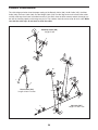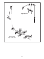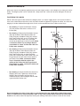
1
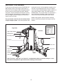
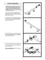
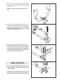
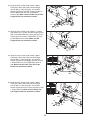
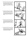
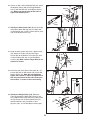
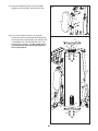
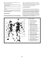
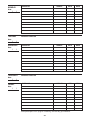
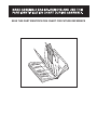
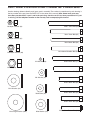
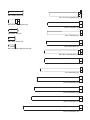
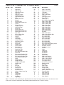
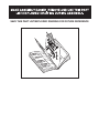
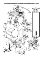
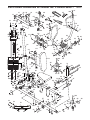
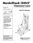
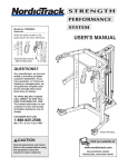
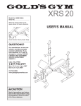
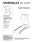
Model No. PFANSY9825.1
Serial No.
Write the serial number in the
space above for reference.
Serial Number Decal (under seat)
QUESTIONS?
As a manufacturer, we are
committed to providing complete customer satisfaction.
If you have questions, or if
there are missing or damaged
parts, please call the telephone number on the warranty
card accompanying this manual or contact the establishment where you purchased
this product.
CAUTION
Read all precautions and instructions in this manual before using
this equipment. Save this manual for future reference.
USER’S MANUAL
TABLE OF CONTENTS
WARNING DECAL PLACEMENT . . . . . . . . . . . . . . . . . . . . . . . . . . . . . . . . . . . . . . . . . . . . . . . . . . . . . . . . . . . . . 2
IMPORTANT PRECAUTIONS . . . . . . . . . . . . . . . . . . . . . . . . . . . . . . . . . . . . . . . . . . . . . . . . . . . . . . . . . . . . . . . . 3
BEFORE YOU BEGIN . . . . . . . . . . . . . . . . . . . . . . . . . . . . . . . . . . . . . . . . . . . . . . . . . . . . . . . . . . . . . . . . . . . . . . 4
ASSEMBLY . . . . . . . . . . . . . . . . . . . . . . . . . . . . . . . . . . . . . . . . . . . . . . . . . . . . . . . . . . . . . . . . . . . . . . . . . . . . . . 5
ADJUSTMENTS . . . . . . . . . . . . . . . . . . . . . . . . . . . . . . . . . . . . . . . . . . . . . . . . . . . . . . . . . . . . . . . . . . . . . . . . . . 23
WEIGHT RESISTANCE CHART . . . . . . . . . . . . . . . . . . . . . . . . . . . . . . . . . . . . . . . . . . . . . . . . . . . . . . . . . . . . . .25
CABLE DIAGRAMS . . . . . . . . . . . . . . . . . . . . . . . . . . . . . . . . . . . . . . . . . . . . . . . . . . . . . . . . . . . . . . . . . . . . . . .26
MAINTENANCE . . . . . . . . . . . . . . . . . . . . . . . . . . . . . . . . . . . . . . . . . . . . . . . . . . . . . . . . . . . . . . . . . . . . . . . . . .28
EXERCISE GUIDELINES . . . . . . . . . . . . . . . . . . . . . . . . . . . . . . . . . . . . . . . . . . . . . . . . . . . . . . . . . . . . . . . . . . 29
ORDERING REPLACEMENT PARTS . . . . . . . . . . . . . . . . . . . . . . . . . . . . . . . . . . . . . . . . . . . . . . . . . .Back Cover
Note: A PART IDENTIFICATION CHART and a PART LIST/EXPLODED DRAWING are attached in the center of
this manual. Remove the PART IDENTIFICATION CHART and PART LIST/EXPLODED DRAWING before beginning assembly.
WARNING DECAL PLACEMENT
The decal shown here
has been placed on the
weight system. If a decal
is missing or illegible,
call the telephone number on the warranty card
accompanying this manual and order a free
replacement decal. Apply
the decal in the location
shown.
PROFORM is a registered trademark of ICON IP, Inc.
2
IMPORTANT PRECAUTIONS
WARNING:
To reduce the risk of serious injury, read the following important precautions
before using the weight system.
1. Read all instructions in this manual before
using the weight system. Use the weight system only as described in this manual.
9. Always wear athletic shoes for foot protection while exercising.
10. Keep hands and feet away from moving parts.
2. It is the responsibility of the owner to ensure
that all users of the weight system are adequately informed of all precautions.
11. Make sure that the cables remain on the pulleys at all times. If the cables bind as you are
exercising, stop immediately and make sure
that the cables are on the pulleys. Replace all
cables at least every two years.
3. The weight system is intended for home use
only. Do not use the weight system in any
commercial, rental, or institutional setting.
12. Always secure the weight stack with the lock
pin and lock after exercising to prevent
unauthorized use of the weight system (see
LOCKING THE WEIGHT STACK on page 24).
4. Use the weight system only on a level surface. Cover the floor beneath the weight system to protect the floor.
5. Keep the weight system indoors, away from
moisture and dust. Do not put the weight
system in a garage or covered patio, or near
water.
13. Always stand on the foot plate when performing an exercise that could cause the
weight system to tip.
14. Never release the arms, leg lever, lat bar, leg
press, ab strap, or handle while weights are
raised. The weights will fall with great force.
6. Make sure all parts are properly tightened
each time the weight system is used.
Replace any worn parts immediately.
7. Keep children under 12 and pets away from
the weight system at all times.
15. Always disconnect the lat bar from the
weight system when performing an exercise
that does not use the lat bar.
8. The weight system is designed to support a
maximum user weight of 300 pounds.
16. If you feel pain or dizziness at any time while
exercising, stop immediately and cool down.
WARNING:
Before beginning this or any exercise program, consult your physician. This
is especially important for persons over the age of 35 or persons with pre-existing health problems.
Read all instructions before using. ICON assumes no responsibility for personal injury or property
damage sustained by or through the use of this product.
3
BEFORE YOU BEGIN
Thank you for selecting the versatile PROFORM® XP
600 S weight system. The weight system offers an
impressive array of weight stations designed to develop every major muscle group of the body. Whether
your goal is to tone your body, build dramatic muscle
size and strength, or improve your cardiovascular system, the weight system will help you to achieve the
specific results you want.
reading this manual, call the telephone number on the
warranty card accompanying this manual. To help us
assist you, please note the product model number and
serial number before calling. The model number is
PFANSY9825.1. The serial number can be found on a
decal attached to the weight system (see the front
cover of this manual for the location of the decal).
Before reading further, please review the drawing
below and familiarize yourself with the parts that are
labeled.
For your benefit, read this manual carefully before
using the weight system. If you have questions after
Right Side
Left Side
High Pulley Station
ASSEMBLED
DIMENSIONS:
Height: 77 in.
Width: 81 in.
Depth: 59 in.
Butterfly Arm
Ab Pulley Station
Backrest
Backrest
Press Arm
Seat
Leg Lever
Leg Press
Low Pulley
Station
Weight
Stack
Foot Plate
Note: The terms “right side” and “left side” are determined relative to a person sitting on a seat;
they do not correspond to right and left on the drawings in the manual.
4
ASSEMBLY
MAKE SURE YOU HAVE THE FOLLOWING
TOOLS:
MAKE ASSEMBLY EASIER
• Two adjustable wrenches
Everything in this manual is designed to
ensure that the weight system can be assembled successfully by anyone. Before beginning assembly, make sure to read the
information on this page. This brief introduction will save you much more time than
it takes to read it.
• One standard screwdriver
• One phillips screwdriver
• One rubber mallet
• You will also need grease or petroleum jelly, a
small amount of soapy water, and clear tape or
masking tape.
ASSEMBLY REQUIRES TWO PERSONS
For your convenience and safety, assemble the
weight system with the help of another person.
Note: Assembly will be more convenient if you have
a socket set, a set of open-end or closed-end
wrenches, or a set of ratchet wrenches.
SET ASIDE ENOUGH TIME
HOW TO IDENTIFY PARTS
Due to the many features of the weight system, the
assembly process will require several hours. By
setting aside plenty of time and by deciding to
make the task enjoyable, assembly will go smoothly.
You may want to assemble the weight system over
a couple of evenings.
To help you identify the small parts used in assembly,
we have included a PART IDENTIFICATION CHART
in the center of this manual. Place the chart on the
floor and use it to easily identify parts during each
assembly step. Note: Some small parts may have
been pre-attached. If a part is not in the parts
bag, check to see if it has been pre-attached.
SELECT A LOCATION
Because of its weight and size, the weight system
should be assembled in the location where it will be
used. Make sure that there is enough room to walk
around the weight system as you assemble it.
HOW TO ORIENT PARTS
HOW TO UNPACK THE BOX
TIGHTENING PARTS
To make assembly as easy as possible, we have
divided the assembly process into four stages. The
parts needed for each stage are found in individual
bags. Important: Wait until you begin each stage
to open the parts bag for that stage. Place all
parts of the weight system in a cleared area and
remove the packing materials. Do not dispose of
the packing materials until assembly is completed.
Tighten all parts as you assemble them, unless
instructed to do otherwise.
As you assemble the weight system, make sure all
parts are oriented exactly as shown in the drawings.
QUESTIONS?
If you have questions after reading these assembly
instructions, see the front cover of this manual.
THE FOUR STAGES OF THE ASSEMBLY PROCESS
Frame Assembly—You will begin by assembling
the base and the uprights that form the skeleton of
the weight system.
Cable Assembly—During this stage you will
attach the cables and pulleys that connect the
arms to the weights.
Arm Assembly—During this stage you will
assemble the arms and the leg lever.
Seat Assembly—During the final stage you will
assemble the seats and the backrests.
5
1
Frame Assembly
1.
Before beginning assembly, make sure you
understand the information in the box on
page 5. See the PART IDENTIFICATION
CHART in the center of this manual for help
identifying small parts.
1
69
Insert four M8 x 75mm Carriage Bolts (69) up
through the Right Base (1). Note: It may be
helpful to place a piece of tape over each bolt
head to hold it in place.
69
2. Insert four M8 x 75mm Carriage Bolts (69) up
through the Left Base (25). Note: It may be helpful to place a piece of tape over each bolt
head to hold it in place.
2
25
69
69
3. Attach the Right Base (1) to the Left Base (25)
with two M8 x 78mm Bolts (82), two M8 Washers
(98), and two M8 Nylon Locknuts (91). Do not
tighten the Locknuts yet.
3
82
98
91
98
25
1
91
4. Attach the Center Base (52) to the Right Base (1)
with two M8 x 78mm Bolts (82), two M8 Washers
(98), and an M8 Nylon Locknut (91). Do not
tighten the Bolts yet.
4
82
Attach the Center Base (52) to the Left Base
(25) in the same manner.
25
98 1
98
98
52
91
6
82
98
5. See drawing A. Attach the Right Upright (2) to
the Right Base (1) with the two indicated M8 x
75mm Carriage Bolts (69) and two M8 Nylon
Locknuts (91). Do not tighten the Locknuts yet.
5A
B
See drawing B. Attach the Left Upright (26) to
the Left Base (25) with the two indicated M8 x
75mm Carriage Bolts (69) and two M8 Nylon
Locknuts (91). Do not tighten the Locknuts yet.
26
2
91
91
25
91
91
1
69
69
6. Attach the Right Seat Frame (3) to the Right
Base (1) with the two indicated M8 x 75mm
Carriage Bolts (69) and two M8 Nylon Locknuts
(91). Do not tighten the Locknuts yet.
6
83
Attach the Right Seat Frame (3) to the Right
Upright (2) with an M8 x 78mm Bolt (82), an M8 x
96mm Bolt (83), an M8 Washer (98), and an M8
Nylon Locknut (91). Do not tighten the Locknut
yet.
2
3
91
98
82
91
91
1
69
7
7. Attach the Left Seat Frame (27) to the Left Base
(25) with the two indicated M8 x 75mm Carriage
Bolts (69) and two M8 Nylon Locknuts (91). Do
not tighten the Locknuts yet.
7
26
98
82
91
Attach the Left Seat Frame (27) to the Left
Upright (26) with two M8 x 78mm Bolts (82), two
M8 Washers (98), and two M8 Nylon Locknuts
(91). Do not tighten the Locknuts yet.
98
27
82
91
25
91
69
8. Orient the Weight Guides (44) with the indicated
holes closer to the bottom. Attach the Weight
Guides inside of the Center Base (52) with two
M8 x 78mm Bolts (82), four M8 Washers (98),
and two M8 Nylon Locknuts (91).
8
44
44
Hole
Hole
82
82
98
52
8
98
98
91
98
91
9. Slide two Weight Bumpers (45) onto the Weight
Guides (44). Slide the eight Weights (55), with the
pin holes on the indicated side, onto the Weight
Guides.
9
44
Grease
56
Press the Weight Tube Bumper (46) into the
Weight Tube (47). Insert the Weight Tube into the
stack of Weights (55). Make sure the pin on the
Weight Tube sits in the groove in the top
Weight.
Pin
47
Grease the indicated holes in the Top Weight (56)
with an included grease pack. Slide the Top
Weight onto the Weight Guides (44).
46
Groove
55
45
10. Attach the Right Top Frame (5) to the Right
Upright (2) with two M8 x 78mm Bolts (82), two
M8 Washers (98), and two M8 Nylon Locknuts
(91). Do not tighten the Locknuts yet. Make
sure the Weight Guides (44) are behind the
Right Top Frame.
45
Pin
Holes
10
82
98
5
98
91
91
44
44
2
11. Attach a Weight Guide (44) to the Right Top
Frame (5) with an M8 x 78mm Bolt (82), two M8
Washers (98), and an M8 Nylon Locknut (91). Do
not tighten the Locknut yet.
11
82
5
98
Repeat this step with the other Weight Guide
(44).
98
91
44
9
44
12. Attach the Left Top Frame (36) to the Right Top
Frame (5) with four M8 x 78mm Bolts (82), two
M8 Washers (98), a Support Plate (31), and four
M8 Nylon Locknuts (91). Do not tighten the
Locknuts yet.
12
36
82
31
98
82
91
98
91
5
13. Attach the Left Top Frame (36) to the Left Upright
(26) with two M8 x 78mm Bolts (82), a Support
Plate (31), and two M8 Nylon Locknuts (91). Do
not tighten the Locknuts yet.
91
13
82
36
31
91
91
14. Orient the Butterfly Frame (14) as shown. Attach
the Butterfly Frame to the Right Upright (2) with
two M8 x 72mm Bolts (85), two M8 Washers (98),
and two M8 Nylon Locknuts (91). Do not tighten
the Locknuts yet.
14
26
82
98
98
5
91
Attach the Butterfly Frame (14) to the Right Top
Frame (5) with two M8 x 78mm Bolts (82), two
M8 Washers (98), and two M8 Nylon Locknuts
(91).
98
Tighten the M8 Nylon Locknuts (91) used in
steps 3–14.
91
91
2
14
85
98
15
Arm Assembly
74—Grease
7
15. Wet the lower end of the Left Butterfly Arm (6)
with soapy water. Slide a Large Foam Pad (15)
onto the Left Butterfly Arm.
Grease
23
14
100
90
Note: an entire grease packet should be used
for this step. Grease an M10 x 85mm Bolt (74)
and the indicated edges of two Arm Bushing (23)
with a grease packet. Attach the Left Butterfly
Arm (6) to the Butterfly Frame (14) with the Bolt
(74), an M10 Large Washer (100), the two Arm
Bushings, and an M10 Nylon Locknut (90). Make
sure the bolt head fits inside of the hole in the
Butterfly Frame.
Grease
23
6
15
Repeat this step with the Right Butterfly Arm
(7).
10
16. Attach the Leg Bumper (59) to the Right Seat
Frame (3) with an M4 x 16mm Self-tapping Screw
(89) and an M4 Washer (96).
16
90
Grease
Grease an M10 x 75mm Bolt (60). Attach the Leg
Lever (4) to the Right Seat Frame (3) with the
Bolt and an M10 Nylon Locknut (90). Make sure
the “U”-rod is on the indicated side of the Leg
Lever. Do not overtighten the Locknut; the
Leg Lever must be able to pivot easily.
4
60
89
96
59
3
“U”-rod
17. Grease an M10 x 108mm Bolt (72). Orient the
Press Frame (29) so that the welded tube is on
the side toward the Left Upright (26). Attach the
Press Frame to the Left Base (25) with the Bolt
and an M10 Nylon Locknut (90). Do not overtighten the Locknut; the Press Frame must be
able to pivot easily.
17
Tube
29
26
Grease
90
72
25
18. Attach a Press Handle (32) to a Press Arm (30)
with an M10 x 65mm Bolt (77), two M10 Washers
(99), two M10 x 12mm Spacers (101), and an
M10 Nylon Locknut (90).
18
81
Attach a Press Arm Cap (34) to the Press Arm
(30) with an M10 x 45mm Button Bolt (81) and an
M10 Large Washer (100).
100
34
Repeat this step with the other Press Arm
(30).
32
30
90
99
30
101
101
99
11
77
19. Attach a Press Arm (30) to the Press Frame (29)
with two M8 x 69mm Bolt (86) and two M8 Nylon
Locknuts (91).
19
Repeat this step with the other Press Arm
(30).
30
86
30
29
20. Grease an M10 x 108mm Bolt (72). Attach the
Leg Press Frame (28) to the Left Base (25) with
the Bolt and an M10 Nylon Locknut (90). Do not
overtighten the Locknut; the Leg Press Frame
must be able to pivot easily.
91
20
28
90
25
72
21. Grease an M10 x 77mm Bolt (76). Attach the
Foot Plate (38) to the Leg Press Frame (28) with
the Bolt and an M10 Nylon Locknut (90). Make
sure the decal on the Foot Plate is right side
up. Do not overtighten the Locknut; the Foot
Plate must be able to pivot easily.
21
90
Grease
76
38
28
22
Cable Assembly
28
22. See the CABLE DIAGRAMS on pages 26 and
27 to identify the cables and to assemble the
cables correctly.
91
Identify the Press Cable (109). Attach the Cable
to the Leg Press Frame (28) with an M8 x 86mm
Shoulder Bolt (37) and an M8 Nylon Locknut (91).
109
37
12
23. Wrap the Press Cable (109) around a 90mm
Pulley (63). Attach the Pulley, two Half Finger
Guards (66), a Cable Trap (68), and an M10
Washer (99) to the Left Seat Frame (27) with an
M10 x 103mm Bolt (22) and an M10 Nylon
Locknut (90). Make sure the Cable Trap and the
Finger Guards are oriented as shown.
23
27
90
63
66
22
68
24. Wrap the Press Cable (109) around a “V”-pulley
(62). Attach the “V”-pulley, two Half Finger Guards
(66), and two M10 Washers (99) to the Leg Press
Frame (28) with an M10 x 115mm Bolt (71) and
an M10 Nylon Locknut (90). Make sure the
Finger Guards are oriented as shown.
109
99 66
24
28
90
109
62
99
71
99
66
25. Wrap the Press Cable (109) around a 90mm
Pulley (63). Attach the Pulley, two Half Finger
Guards (66), a Cable Trap (68), and an M10
Washer (99) to the Left Upright (26) with an M10
x 108mm Bolt (72) and an M10 Nylon Locknut
(90). Make sure the Cable Trap and Finger
Guards are oriented as shown.
66
25
26
63 99
68
66
90
72
109
66
26. Wrap the Press Cable (109) around a 90mm
Pulley (63). Attach the Pulley, two Half Finger
Guards (66), a Cable Trap (68), and an M10
Washer (99) to the Press Frame (29) with an M10
x 135mm Bolt (70). Make sure the Cable Trap
and Finger Guards are oriented as shown.
26
29
109
66
99
70
68
13
63
66
27. Wrap the Press Cable (109) around a “V”-pulley
(62). Attach the “V”-pulley, two Half Finger Guards
(66), a Large Cable Trap (111), and an M10
Washer (99) inside the bracket on the Left
Upright (26) with an M10 x 65mm Bolt (77) and
an M10 Nylon Locknut (90). Make sure the
Cable Trap and Finger Guards are oriented as
shown.
27
66
99
62
109
77
26
111
66
90
28. Wrap the Press Cable (109) around a 90mm
Pulley (63). Attach the Pulley, two Half Finger
Guards (66), a Cable Trap (68), and an M10
Washer (99) to the Press Frame (29) with the
M10 x 135mm Bolt (70) used in step 26 and an
M10 Nylon Locknut (90). Make sure the Cable
Trap and Finger Guards are oriented as
shown.
28
66
90
63
109
99 68
66
29
70
29. Wrap the Press Cable (109) under a 90mm
Pulley (63). Attach the Pulley, two M10 Washers
(99), and two Half Finger Guards (66) inside the
bracket on the Left Base (25) with an M10 x
50mm Bolt (64) and an M10 Nylon Locknut (90).
Make sure the Finger Guards are oriented as
shown.
29
66
63
99
99
66
64
90
109
25
30. Wrap the Press Cable (109) over a 90mm Pulley
(63). Attach the Pulley and a Cable Trap (68) to
the Right Top Frame (5) with an M10 x 45mm
Bolt (80) and an M10 Nylon Locknut (90). Make
sure the Cable Trap is oriented to hold the
Cable in the groove of the Pulley.
30
80
68
63
5
90
109
14
31. Attach the end of the Press Cable (109) to a “U”bracket (50) with an M8 Washer (98) and an M8
Nylon Locknut (91). Note: Do not completely
tighten the Locknut; it should be tightened so
that only two threads of the Cable show past
the Locknut, as shown in the inset drawing.
31
109
109
98
50
32. Identify the Butterfly Cable (106). Grease an
M8 x 22mm Shoulder Bolt (39). Attach the Cable
to the Left Butterfly Arm (6) with the Bolt and an
M8 Nylon Locknut (91). Make sure the flat edge
of the Cable is against the Butterfly Arm.
91
91
32
39 Grease
106
6
91
Flat
Edge
33. Wrap the Butterfly Cable (106) over a “V”-pulley
(62). Attach the “V”-pulley, a Large Cable Trap
(111), an M10 Washer (99), and two Full Finger
Guards (104) to the Right Upright (2) with an M10
x 62mm Bolt (73) and an M10 Nylon Locknut
(90).
33
2
106
111
90
62
73
104
34. Wrap the Butterfly Cable (106) under a 90mm
Pulley (63). Attach the Pulley and two Half Finger
Guards (66) to the Double “U”-bracket (61) with
an M10 x 48mm Bolt (84) and an M10 Nylon
Locknut (90). Make sure the Finger Guards are
oriented as shown.
99
34
104
106
63
66
90
66
61
84
35. Wrap the Butterfly Cable (106) over a “V”-pulley
(62). Attach the “V”-pulley, a Large Cable Trap
(111), an M10 Washer (99), and two Full Finger
Guards (104) to the Right Upright (2) with an M10
x 62mm Bolt (73) and an M10 Nylon Locknut
(90).
35
73
104
62
106
99
111
2
104
90
15
36. Grease an M8 x 22mm Shoulder Bolt (39). Attach
the Butterfly Cable (106) to the Right Butterfly
Arm (7) with the Bolt and an M8 Nylon Locknut
(91). Make sure the flat edge of the Cable is
against the Butterfly Arm.
36
Grease
39
106
7
91
Flat
Edge
37. Identify the Short Cable (108). Attach the Cable
to the M8 x 96mm Bolt (83) used in step 6 with
an M8 Washer (98), an M8 x 13mm Spacer (103),
and an M8 Nylon Locknut (91).
37
108
98
2
91
103
83
38. Wrap the Short Cable (108) over a 90mm Pulley
(63). Attach the Pulley and two Half Finger
Guards (66) to the Double “U”-bracket (61) with
an M10 x 48mm Bolt (84) and an M10 Nylon
Locknut (90). Make sure the Finger Guards are
oriented as shown.
38
90
61
66
66
108
84
63
39. Attach the end of the Short Cable (108) to a “U”bracket (50) with an M8 Washer (98) and an M8
Nylon Locknut (91). Note: Do not completely
tighten the Locknut; it should be tightened so
that only two threads of the Cable show past
the Locknut, as shown in the inset drawing.
39
108
98
108
50
91
91
40. Identify the Weight Cable (110). Route the
Cable up through the Right Top Frame (5) and
over a 90mm Pulley (63). Attach the Pulley inside
the Top Frame with an M10 x 80mm Bolt (75),
two M10 Washers (99), two M10 x 19mm
Spacers (102), and an M10 Nylon Locknut (90).
40
110
99
63
75
102
99
5
16
102
90
41. Route the Weight Cable (110) over a 90mm
Pulley (63) and down through the Right Top
Frame (5). Attach the Pulley inside the Top Frame
with an M10 x 80mm Bolt (75), two M10 Washers
(99), two M10 x 19mm Spacers (102), and an
M10 Nylon Locknut (90).
41
75
102
99
90
99
63
110
42. Wrap the Weight Cable (110) under a 90mm
Pulley (63). Attach the Pulley, a Cable Trap (68),
and two Half Finger Guards (66) at the second
hole from the top of the two Pulley Plates (51)
with an M10 x 50mm Bolt (64) and an M10 Nylon
Locknut (90). Make sure the Cable Trap and
Finger Guards are oriented as shown.
42
5
110
64
63
66
66
90
68
51
51
43. Wrap the Weight Cable (110) over a 90mm Pulley
(63). Attach the Pulley to the indicated bracket on
the Right Top Frame (5) with an M10 x 45mm
Bolt (80) and an M10 Nylon Locknut (90).
43
Bracket
5
90
80 63
44. Wrap the Weight Cable (110) over a 90mm Pulley
(63). Attach the Pulley and a Cable Trap (68) to
the indicated bracket on the Right Top Frame (5)
with an M10 x 45mm Bolt (80) and an M10 Nylon
Locknut (90). Make sure the Cable Trap is oriented to hold the Cable in the groove of the
Pulley.
44
Bracket
Attach pulley
on this side
80 5
63
90
45. Set the M12 Washer (33) on top of the Weight
Tube (47). Thread the M12 Nut (49) all the way
onto the Weight Cable (110).
68
110
45
110
49
Thread the Weight Cable (110) into the Weight
Tube (47) a couple of turns.
33
47
17
110
46. Identify the Ab Cable (107). Route the small ball
on the Cable through the Leg Lever (4) and the
Right Seat Frame (3). Make sure the Cable is
over the rod in the Seat Frame.
46
3
90
4
63
101
Attach a 90mm Pulley (63) inside the Leg Lever
(4), over the Ab Cable (107), with an M10 x
65mm Bolt (77), two M10 Washers (99), two M10
x 12mm Spacers (101), and an M10 Nylon
Locknut (90).
Large
Ball
99
99
107
Rod
77
101
47. Attach a 90mm Pulley (63) inside the Right Seat
Frame (3), over the Ab Cable (107), with an M10
x 45mm Bolt (80) and an M10 Nylon Locknut
(90).
47
63
90
3
107
80
48. Route the Ab Cable (107) through the Right
Upright (2) and under a 90mm Pulley (63). Attach
the Pulley and two Half Finger Guards (66) to the
Right Base (1) with an M10 x 50mm Bolt (64) and
an M10 Nylon Locknut (90). Make sure the
Finger Guards are oriented as shown.
48
90 66
63
66
64
107
1
2
49. Wrap the Ab Cable (107) over a 90mm Pulley
(63). Attach the Pulley, a Cable Trap (68), and
two Half Finger Guards (66) to the lower hole in
the indicated “U”-bracket (50) with an M10 x
50mm Bolt (64) and an M10 Nylon Locknut (90).
Make sure the Cable Trap and Finger Guards
are oriented as shown.
49
90 66
50
66
68
64
63
107
18
50. Wrap the Ab Cable (107) under a 90mm Pulley
(63). Attach the Pulley, a Cable Trap (68), and
two Half Finger Guards (66) to the Right Base (1)
with an M10 x 50mm Bolt (64) and an M10 Nylon
Locknut (90). Make sure the Cable Trap and
Finger Guards are oriented as shown.
50
90 66
107
63
1
68
66
64
51. Wrap the Ab Cable (107) over a 90mm Pulley
(63). Attach the Pulley, a Cable Trap (68), and
two Half Finger Guards (66) at the second hole
from the bottom of the two Pulley Plates (51) with
an M10 x 50mm Bolt (64) and an M10 Nylon
Locknut (90). Make sure the Cable Trap and
Finger Guards are oriented as shown.
51
66
64
51
90
68
63
107
52. Wrap the Ab Cable (107) under a 90mm Pulley
(63). Attach the Pulley, a Cable Trap (68), and
two Half Finger Guards (66) to the Right Base (1)
with an M10 x 50mm Bolt (64) and an M10 Nylon
Locknut (90). Make sure the Cable Trap and
Finger Guards are oriented as shown.
52
90
66
66
107
63
68
1
66
53. Wrap the Ab Cable (107) over a 90mm Pulley
(63). Attach the Pulley, a Cable Trap (68), and
two Half Finger Guards (66) to the lower hole in
the indicated “U”-bracket (50) with an M10 x
50mm Bolt (64) and an M10 Nylon Locknut (90).
Make sure the Cable Trap and Finger Guards
are oriented as shown.
53
50
66
64
90
66
64
68
63
107
54. Wrap the Ab Cable (107) under a 90mm Pulley
(63). Attach the Pulley, a Cable Trap (68) and two
Half Finger Guards (66) to the Right Base (1) with
an M10 x 50mm Bolt (64) and an M10 Nylon
Locknut (90). Make sure the Cable Trap and
Finger Guards are oriented as shown.
54
90
66
107
1
66
63
64
68
19
55. Wrap the Ab Cable (107) over a 90mm Pulley
(63). Attach the Pulley and the two Quarter Finger
Guards (105) to the Right Upright (2) with an M10
x 108mm Bolt (72), an M10 Washer (99), and an
M10 Nylon Locknut (90). Make sure that the rod
is inserted through both Finger Guards and is
over the Cable.
55
Rod
105
90
99
63
105
72
107
2
56. Tighten the Weight Cable (110) into the Weight
Tube (not shown) until all the slack is taken out of
the cables. Tighten the M12 Nut (49) on the
Weight Cable against the M12 Washer (33).
56
110
33
Seat Assembly
57
26
49
88
53
113
57. Attach the Press Backrest (113) to the Backrest
Frame (53) with two M6 x 16mm Screws (88), an
M6 x 35mm Screw (78), and an M6 Washer (97).
43
78
Slide the Backrest Frame (53) into the Left
Upright (26). Engage the Knob (43) into the
Upright and Backrest Frame, and turn it clockwise
until it is tight.
97
58. Attach a Seat (8) to the Left Seat Frame (27) with
four M6 x 16mm Screws (88).
58
8
Repeat this step with the other Seat (8) and
the Right Seat Frame (not shown).
27
88
88
20
59. Attach the Butterfly Backrest (9) to the Right
Upright (2) with four M6 x 16mm Screws (88).
59
88
2
9
60. Press the two Shroud Covers (11) onto the
Shroud (10). Attach the Shroud to the Right Top
Frame (5) and the Center Base (52) with four M6
x 22mm Bolts (87), four M6 Washers (97), and
four M6 Nylon Locknuts (92). Be careful not to
scratch yourself when reaching through the
hole in the Shroud.
88
60
11
92
92
5
97
97
87
10
52
92
92
97
97
87
21
11
61. Attach the Lock Plate (21) to the Right Seat
Frame (3) with an M8 x 68mm Shoulder Bolt (41),
an M8 Washer (98), and an M8 Nylon Locknut
(91). Do not overtighten the Locknut; the Lock
Plate must be able to pivot easily.
61
91
3
98
89
24
Attach the Leg Pin (24) to the Right Seat Frame
(3) with an M4 x 16mm Self-tapping Screw (89).
Insert the Leg Pin through the Leg Lever (4) and
the Lock Plate (21).
21
4
41
62. Insert the Long Pad Tube (16) into the Right Seat
Frame (3). Slide two Small Foam Pads (18) onto
the Pad Tube. Press two Foam Caps (17) into the
Pad Tube.
62
17
18
3
Repeat this step with the Leg Lever (4) and
the Short Pad Tube (35).
16
18
4
17
35
63. Make sure that all parts have been properly tightened. The use of the remaining parts will be explained in
ADJUSTMENTS, beginning on the following page.
Before using the weight system, pull each cable a few times to make sure that the cables move smoothly
over the pulleys. If one of the cables does not move smoothly, find and correct the problem. IMPORTANT: If
the cables are not properly installed, they may be damaged when heavy weight is used. See the
CABLE DIAGRAMS on pages 26 and 27 of this manual for proper cable routing. If there is any slack
in the cables, you will need to remove the slack by tightening the cables. See MAINTENANCE on
page 28.
22
ADJUSTMENTS
This section explains how to adjust the weight system. See the EXERCISE GUIDELINES on page 29 for important
information about how to get the most benefit from your exercise program. Also, see the accompanying exercise
guide to see the correct form for each exercise.
Make sure all parts are properly tightened each time the weight system is used. Replace any worn parts immediately. The weight system can be cleaned with a damp cloth and a mild, non-abrasive detergent. Do not use solvents.
CHANGING THE WEIGHT SETTING
To change the setting of the weight stack, insert the
Weight Pin (57) under the desired Weight (55). Insert
the Weight Pin so that the bent end touches the
weight stack. Turn the bent end down. Note: Be
careful not to scratch yourself when reaching
through the hole in the Shroud (10). Do not use
the Top Weight (56, not shown) by itself.
55
Note: Due to the cables and pulleys, the amount
of resistance at each exercise station may vary
from the weight setting. Use the WEIGHT
RESISTANCE CHART on page 25 to find the
approximate amount of resistance at each weight
station.
10
57
ATTACHING THE ACCESSORIES TO A PULLEY
STATION
Attach the Handle (93) to the Ab Cable (107) at the low
pulley station with a Cable Clip (95). For some exercises, the Chain (94) should be attached between the
Handle and the Cable with two Cable Clips. Adjust the
length of the Chain between the Handle and the
Cable so that the Handle is in the correct starting
position for the exercise to be performed.
21
95
94
107
95
The Lat Bar (not shown), the Ab Strap (79), or the
Handle (93) can be attached at any pulley station in
the same manner. Always engage the Lock Plate (21)
when using the low pulley station (see USING THE
LOCK PLATE below).
93
USING THE LOCK PLATE
When using the low pulley station, engage the Leg
Pin (24) into the Leg Lever (4) and the Lock Plate
(21).
4
24
To use the Leg Lever (4), engage the Leg Pin (24)
into the Right Seat Frame (3) and the Lock Plate (21).
21
3
23
ADJUSTING THE BACKREST
26
To adjust the position of the Press Backrest (113),
disengaging the Knob (43) from the Left Upright (26)
and move the Backrest to the desired position.
Reengage the Knob into the Left Upright and the
Backrest Frame (53). Make sure the Knob is fully
tightened.
53
113
43
LOCKING THE WEIGHT STACK
44
Lock the weight stack by inserting the Lock Pin (65)
through a Weight Guide (44) and securing the Lock
(48) onto the Lock Pin.
65
24
48
WEIGHT RESISTANCE CHART
The chart below shows the approximate weight resistance at each exercise station. “Top” refers to the 6 lb. top
weight. The other numbers refer to the 12.5 lb. weight plates. Weight resistance shown for the butterfly arm station is for each arm. Note: The actual resistance at each station may vary due to differences in individual
weight plates as well as friction between the cables, pulleys, and weight guides.
WEIGHT
HIGH
PULLEY
(lbs.)
BUTTERFLY ARM
(lbs.)
PRESS
ARM
(lbs.)
LEG
LEVER
(lbs.)
LOW
PULLEY
(lbs.)
LEG
PRESS
(lbs.)
AB
STATION
(lbs.)
Top
10
16
31
11
27
45
19
1
25
30
48
22
35
59
27
2
38
45
81
39
43
84
41
3
54
51
97
49
61
118
60
4
67
60
120
66
71
146
73
5
84
73
138
85
87
162
90
6
97
88
150
94
107
193
100
7
105
93
176
106
120
223
114
8
122
106
214
126
143
248
130
25
CABLE DIAGRAMS
The cable diagrams below show the proper routing of the Butterfly Cable (106), the Ab Cable (107), the Short
Cable (108), the Press Cable (109), and the Weight Cable (110). Use the diagram to make sure that the cables
and the cable traps have been assembled correctly. If the cables have not been correctly routed, the weight system will not function properly and damage may occur. The numbers show the correct route for each cable. Make
sure that the cable traps do not touch or bind the cables.
Butterfly Cable (106)
Length: 5 feet
4
2
5
1
3
6
10
2
1
3
4
Short Cable (108)
Length: 3 feet 11 inches
8
5
3
7
2
1
9
26
Ab Cable (107)
Length: 21 feet 1 inch
9
5
2
1
4
3
Weight Cable (110)
Length: 12 feet 1 inch
10
6
6
8
7
4
Press Cable (109)
Length: 22 feet 6 inches
5
3
2
1
27
MAINTENANCE
Make sure all parts are properly tightened each time the weight system is used. Replace any worn parts immediately. The weight system can be cleaned with a damp cloth and a mild, non-abrasive detergent. Do not use
solvents.
TIGHTENING THE CABLES
Woven cable, the type of cable used on the weight system, can stretch slightly when it is first used. If there is
slack in the cables before resistance is felt, the cables should be tightened. To tighten the cables, first insert the
weight pin into the middle of the weight stack. Slack can be removed from these cables several ways:
•
See drawing 1. Tighten the M8 Nylon Locknut
(91) that connects the end of a cable to a “U”bracket (50).
•
See drawing 1. Remove the M10 Nylon Locknut
(90) and the M10 x 50mm Bolt (64) from the
Cable Trap (68), the 90mm Pulley (63), the two
Half Finger Guards (66), and a “U”-bracket (50).
Reattach the Pulley, Cable Trap, and Finger
Guards to the other hole in the “U”-bracket. Make
sure that the Cable Trap and Finger Guards
are oriented as shown and that the cable and
Pulley move smoothly.
•
•
1
90 66
50
91
66
68
63
See drawing 2. Remove the M10 Nylon Locknut
(90) and the M10 x 50mm Bolt (64) from the
Cable Trap (68), the 90mm Pulley (63), the two
Half Finger Guards (66), and the two Pulley
Plates (51). Reattach the Pulley, Cable Trap, and
Finger Guards to a hole closer to the center of
the Pulley Plates. Make sure that the Cable
Trap is oriented to hold the cable in the
groove of the Pulley, that the Finger Guards
are oriented as shown, and that the Cable and
Pulley move smoothly.
2
See drawing 3. Loosen the M12 Nut (49) on the
Weight Cable (110). Tighten the Cable into the
Weight Tube (not shown) until the slack is
removed from the Cable. Retighten the M12 Nut
against the M12 Washer (33).
3
64
64
51
66
66
68
63
90
110
49
33
Do not overtighten the cables. If the cables are overtightened, the top weight will be lifted off the weight
stack. If a cable tends to slip off the pulleys often, it may have become twisted. Remove the cable and reinstall it. If the cables need to be replaced, see the part ordering information on the back cover of this manual.
28
EXERCISE GUIDELINES
THE FOUR BASIC TYPES OF WORKOUTS
PERSONALIZING YOUR EXERCISE PROGRAM
Muscle Building
To increase the size and strength of your muscles,
push them close to their maximum capacity. Your muscles will continually adapt and grow as you progressively increase the intensity of your exercise. You can
adjust the intensity level of an individual exercise in
two ways:
• by changing the amount of weight used
• by changing the number of repetitions or sets performed. (A “repetition” is one complete cycle of an
exercise, such as one sit-up. A “set” is a series of
repetitions.)
Determining the exact length of time for each workout,
as well as the number of repetitions or sets completed,
is an individual matter. It is important to avoid overdoing it during the first few months of your exercise program. You should progress at your own pace and be
sensitive to your body’s signals. If you experience pain
or dizziness at any time while exercising, stop immediately and begin cooling down. Find out what is wrong
before continuing. Remember that adequate rest and a
proper diet are important factors in any exercise program.
WARMING UP
The proper amount of weight for each exercise
depends upon the individual user. You must gauge
your limits and select the amount of weight that is right
for you. Begin with 3 sets of 8 repetitions for each
exercise you perform. Rest for three minutes after
each set. When you can complete 3 sets of 12 repetitions without difficulty, increase the amount of weight.
Begin each workout with 5 to 10 minutes of stretching
and light exercise to warm up. Warming up prepares
your body for more strenuous exercise by increasing
circulation, raising your body temperature and delivering more oxygen to your muscles.
WORKING OUT
Toning
You can tone your muscles by pushing them to a moderate percentage of their capacity. Select a moderate
amount of weight and increase the number of repetitions in each set. Complete as many sets of 15 to 20
repetitions as possible without discomfort. Rest for one
minute after each set. Work your muscles by completing more sets rather than by using high amounts of
weight.
Weight Loss
To lose weight, use a low amount of weight and
increase the number of repetitions in each set.
Exercise for 20 to 30 minutes, resting for a maximum
of 30 seconds between sets.
Each workout should include 6 to 10 different exercises. Select exercises for every major muscle group,
emphasizing areas that you want to develop most. To
give balance and variety to your workouts, vary the
exercises from session to session.
Schedule your workouts for the time of day when your
energy level is the highest. Each workout should be
followed by at least one day of rest. Once you find the
schedule that is right for you, stick with it.
EXERCISE FORM
Cross Training
Cross training is an efficient way to get a complete and
well-balanced fitness program. An example of a balanced program is:
• Plan strength training workouts on Monday,
Wednesday, and Friday.
• Plan 20 to 30 minutes of aerobic exercise, such as
running on a treadmill or riding on an exercise cycle,
on Tuesday and Thursday.
• Rest from both strength training and aerobic exercise
for at least one full day each week to give your body
time to regenerate.
The combination of strength training and aerobic exercise will reshape and strengthen your body, plus develop your heart and lungs.
29
Maintaining proper form is an essential part of an
effective exercise program. This requires moving
through the full range of motion for each exercise, and
moving only the appropriate parts of the body.
Exercising in an uncontrolled manner will leave you
feeling exhausted. On the exercise guide accompanying this manual you will find photographs showing the
correct form for several exercises, and a list of the
muscles affected. See the muscle chart on the next
page to find the names of the muscles.
The repetitions in each set should be performed
smoothly and without pausing. The exertion stage of
each repetition should last about half as long as the
return stage. Proper breathing is important. Exhale
during the exertion stage of each repetition and inhale
during the return stroke. Never hold your breath.
slowly as you stretch and do not bounce. Ease into
each stretch gradually and go only as far as you can
without strain. Stretching at the end of each workout
is an effective way to increase flexibility.
Rest for a short period of time after each set. The
ideal resting periods are:
• Rest for three minutes after each set for a muscle
building workout.
• Rest for one minute after each set for a toning workout.
• Rest for 30 seconds after each set for a weight loss
workout.
Plan to spend the first couple of weeks familiarizing
yourself with the equipment and learning the proper
form for each exercise.
STAYING MOTIVATED
For motivation, keep a record of each workout. The
chart on page 31 of this manual can be photocopied
and used to schedule and record your workouts. List
the date, the exercises performed, the weight used,
and the numbers of sets and repetitions completed.
Record your weight and key body measurements at
the end of every month. Remember, the key to achieving the greatest results is to make exercise a regular
and enjoyable part of your everyday life.
COOLING DOWN
End each workout with 5 to 10 minutes of stretching.
Include stretches for both your arms and legs. Move
MUSCLE CHART
O
A
P
L
B
Q
C
R
D
S
E
T
F
G
M
U
N
H
V
I
W
J
X
K
30
A.
B.
C.
D.
E.
F.
G.
H.
I.
J.
K.
L.
M.
N.
O.
P.
Q.
R.
S.
T.
U.
V.
W.
X.
Sternomastoid (neck)
Pectoralis Major (chest)
Biceps (front of arm)
Obliques (waist)
Brachioradials (forearm)
Hip Flexors (upper thigh)
Abductor (outer thigh)
Quadriceps (front of thigh)
Sartorius (front of thigh)
Tibialis Anterior (front of calf)
Soleus (front of calf)
Anterior Deltoid (shoulder)
Rectus Abdominus (stomach)
Adductor (inner thigh)
Trapezius (upper back)
Rhomboideus (shoulder)
Posterior Deltoid (Upper Back)
Triceps (back of arm)
Latissimus Dorsi (mid back)
Spinae Erectors (lower back)
Gluteus Medius (hip)
Gluteus Maximus (buttocks)
Hamstring (back of leg)
Gastrocnemius (back of calf)
EXERCISE
MONDAY
WEIGHT
SETS
REPS
WEIGHT
SETS
REPS
WEIGHT
SETS
REPS
Date:
/
/
AEROBIC EXERCISE
TUESDAY
Date:
/
/
WEDNESDAY
EXERCISE
Date:
/
/
THURSDAY
AEROBIC EXERCISE
Date:
/
/
EXERCISE
FRIDAY
Date:
/
/
Make photocopies of this page for scheduling and recording your workouts.
31
SAVE THIS PART IDENTIFICATION CHART FOR FUTURE REFERENCE
PART IDENTIFICATION CHART—Model No. PFANSY9825.1
See the drawings below to identify small parts used in assembly. The number in parentheses by each drawing is
the key number of the part, from the PART LIST in the center of this manual. Note: Some small parts may
have been pre-attached. If a part is not in the parts bag, check to see if it has been pre-attached. If a part
is missing, call the telephone number on the warranty card accompanying this manual.
M6 Nylon Locknut (92)
M10 x 75mm Bolt (60)
M8 x 72mm Bolt (85)
M8 Nylon Locknut (91)
M8 x 69mm Bolt (86)
M8 x 68mm Shoulder Bolt (41)
M10 Nylon Locknut (90)
M4 Washer (96)
M10 x 65mm Bolt (77)
M12 Nut (49)
M10 x 62mm Bolt (73)
M6 Washer (97)
M10 x 50mm Bolt (64)
M12 Washer (33)
M8 Washer (98)
M10 x 48mm Bolt (84)
M10 x 45mm Bolt (80)
M10 Large Washer (100)
M10 Washer (99)
M10 x 45mm Button Bolt (81)
M6 x 35mm Screw (78)
M8 x 75mm Carriage Bolt (69)
M8 x 22mm Shoulder Bolt (39)
M10 x 77mm Bolt (76)
M6 x 22mm Bolt (87)
M8 x 78mm Bolt (82)
M6 x 16mm Screw (88)
M10 x 80mm Bolt (75)
M4 x 16mm Self-tapping Screw (89)
M8 x 86mm Shoulder Bolt (37)
M10 x 85mm Bolt (74)
M8 x 96mm Bolt (83)
M10 x 103mm Bolt (22)
M10 x 108mm Bolt (72)
M10 x 115mm Bolt (71)
M10 x 135mm Bolt (70)
PART LIST—Model No. PFANSY9825.1
Key No.
Qty.
1
2
3
4
5
6
7
8
9
10
11
12
13
14
15
16
17
18
19
20
21
22
23
24
25
26
27
28
29
30
31
32
33
34
35
36
37
38
39
40
41
42
43
44
45
46
47
48
49
50
51
52
53
54
55
56
57
58
59
1
1
1
1
1
1
1
2
1
1
2
1
1
1
2
1
4
4
6
7
1
1
4
1
1
1
1
1
1
2
2
2
2
2
1
1
1
1
2
1
1
1
1
2
2
1
1
1
1
2
2
1
1
1
8
1
1
2
1
Description
Right Base
Right Upright
Right Seat Frame
Leg Lever
Right Top Frame
Left Butterfly Arm
Right Butterfly Arm
Seat
Butterfly Backrest
Shroud
Shroud Cover
50mm Round Inner Cap
Lat Bar
Butterfly Frame
Large Foam Pad
Long Pad Tube
Foam Cap
Small Foam Pad
63mm Round Inner Cap
50mm Round Inner Cap
Lock Plate
M10 x 103mm Bolt
Arm Bushing
Leg Pin
Left Base
Left Upright
Left Seat Frame
Leg Press Frame
Press Frame
Press Arm
Support Plate
Press Handle
M12 Washer
Press Arm Cap
Short Pad Tube
Left Top Frame
M8 x 86mm Shoulder Bolt
Foot Plate
M8 x 22mm Shoulder Bolt
50mm Round Outer Cap
M8 x 68mm Shoulder Bolt
56mm Round Inner Cap
Knob
Weight Guide
Weight Bumper
Weight Tube Bumper
Weight Tube
Lock
M12 Nut
“U”-bracket
Pulley Plate
Center Base
Backrest Frame
25mm x 40mm Inner Cap
Weight
Top Weight
Weight Pin
Handgrip
Leg Bumper
Key No. Qty.
60
61
62
63
64
65
66
67
68
69
70
71
72
73
74
75
76
77
78
79
80
81
82
83
84
85
86
87
88
89
90
91
92
93
94
95
96
97
98
99
100
101
102
103
104
105
106
107
108
109
110
111
112
113
#
#
#
#
1
1
4
23
9
1
34
2
13
8
1
1
4
2
2
2
1
4
1
1
4
2
23
1
2
2
4
4
14
2
34
42
4
1
1
4
1
5
29
22
4
6
4
1
4
2
1
1
1
1
1
3
2
1
1
1
2
1
R0306A
Description
M10 x 75mm Bolt
Double “U”-bracket
“V”-pulley
90mm Pulley
M10 x 50mm Bolt
Lock Pin
Half Finger Guard
Base Bushing
Cable Trap
M8 x 75mm Carriage Bolt
M10 x 135mm Bolt
M10 x 115mm Bolt
M10 x 108mm Bolt
M10 x 62mm Bolt
M10 x 85mm Bolt
M10 x 80mm Bolt
M10 x 77mm Bolt
M10 x 65mm Bolt
M6 x 35mm Screw
Ab Strap
M10 x 45mm Bolt
M10 x 45mm Button Bolt
M8 x 78mm Bolt
M8 x 96mm Bolt
M10 x 48mm Bolt
M8 x 72mm Bolt
M8 x 69mm Bolt
M6 x 22mm Bolt
M6 x 16mm Screw
M4 x 16mm Self-tapping Screw
M10 Nylon Locknut
M8 Nylon Locknut
M6 Nylon Locknut
Handle
Chain
Cable Clip
M4 Washer
M6 Washer
M8 Washer
M10 Washer
M10 Large Washer
M10 x 12mm Spacer
M10 x 19mm Spacer
M8 x 13mm Spacer
Full Finger Guard
Quarter Finger Guard
Butterfly Cable
Ab Cable
Short Cable
Press Cable
Weight Cable
Large Cable Trap
20mm x 40mm Inner Cap
Press Backrest
User’s Manual
Exercise Guide
Grease Packet
Allen Wrench
Note: “#” indicates a non-illustrated part. Specifications are subject to change without notice. See the back cover
of the user’s manual for information about ordering replacement parts or if a part is missing.
81
SAVE THIS PART LIST/EXPLODED DRAWING FOR FUTURE REFERENCE
EXPLODED DRAWING A—Model No. PFANSY9825.1
68 63
80
99
102 63
75
82
102
99
98 90
98
98 98
63
75
90
5 92
63
80
99
102
90
102
99 74
39 106
19
97
58
92
73 104
62
111
104
10
91
14
100
39
90
20
104
91
90
90
99
91
8
91 111 62 99
98
85
106
23
97
87
87
91 91
100
90
23 42
15
13
58
99
80 63
91
74
7
23
11
90 90
68
110
23
R0306A
90
104
73
105
6
63
88
17
72
88
9
20
18
107
16
105
88
15
17
18
108
35
98
18
17
20
98
88
91
2
91
82
88
98
4
89 96
21
11
90
89
20
90
103 91
83
90
18
24
20
17
59
3
91
90
91
60
41
66
90
68
91
66
63
66
64
82
66
82
66
64
63
66 64
80
1
20
69
107
19
63
63
63
101
99
77
87
90
66
90
88
97
97
68
101
99
66
69
68
64
EXPLODED DRAWING B—Model No. PFANSY9825.1
31
36
19
82 98
82
82
82
91
91
98
66
61
19
100
32
34
98
91 91
33
77
66
64
68 63
91
90 99101
30
47
68
77 66
66 63
66
53
98
98
91
68
99
91
19
90
8
68
63 66
62
99
111
72
91
63
99
98
90 66
66
66
63 91
98
98
82
66
91
90
27
64
66
99
82
82
109
72
37
33
98
91
88
66
98
90
91
108
40
50
99
67
52
69
90
66 28
71
67
82
62 99
99
76
64
66
90
88
25
90
38
112
66
66
98
12
91
77
98
44
90
98
78
97
91
72
50
90
98
82
68
109
113
54
91
29
99
70
55 43
57
99
99
112
88
65
46
68
90 101
63
48
63
66
30
51
66
26
66 90
86
51
66
45
101
99
63
56
82
90 99
101
32
84
49
91
81 79
66
66
110
98
34
93 94
66
90
84
31
82
90
63
81
100
95
R0306A
68
66
63
98
91
68
98
92
91
92
91
22
66
69
19
64
63
66
90
ORDERING REPLACEMENT PARTS
To order replacement parts, please call the telephone number on the warranty card accompanying this manual.
To help us assist you, be prepared to provide the following information:
1. the MODEL NUMBER of the product (PFANSY9825.1)
2. the NAME of the product (PROFORM XP 600 S weight system)
3. the SERIAL NUMBER of the product (see the front cover of this manual)
4. the KEY NUMBER and DESCRIPTION of the part(s) (see the PART LIST and EXPLODED DRAWING in the
centre of this manual)
Part No. 237995 R0306A
Printed in China © 2006 ICON IP, Inc.