1
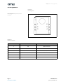
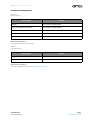
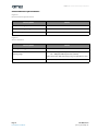
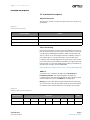
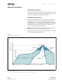
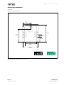
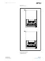
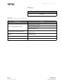
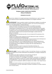
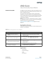
iAQ-Core
Indoor Air Quality Sensor Module
General Description
The iAQ-Core sensor module is used to measure VOC levels and
provide CO 2 equivalent and TVOC equivalent predictions. The
data is available via I²C bus.
The sensor itself is protected by a plastic cap and a filter
membrane. The sensor module can be soldered directly to a
host circuit board with selective or reflow soldering via the edge
connectors. The sensor is protected by a membrane, which
should not be removed.
Note(s): Please read the I²C addressing instructions carefully.
An undefined use of the I²C interface could harm the iAQ-Core
module and cause a loss of functionality.
Ordering Information and Content Guide appear at end of
datasheet.
Key Benefits & Features
The benefits and features of iAQ-Core, Indoor Air Quality sensor
module are listed below:
Figure 1:
Added Value of Using iAQ-Core Sensor Module
Benefits
Features
• Reliable evaluation of indoor air
quality
• Output of relative CO2 equivalents (ppm) and TVOC
equivalents (ppb)
• High sensitivity and fast response
• Sensing range: 450 – 2000 ppm CO2 equivalents
125 – 600 ppb TVOC equivalents
• I²C interface
• Micro size for convenient installation
•
•
•
•
• Low power consumption
• 66 mW (maximum in continuous mode)
• 9 mW (maximum in pulsed mode)
MEMS metal oxide sensor technology
SMD type package
Reflow capable
Module with automatic baseline correction
Applications
• Smart Home
• Internet of Things
• HVAC
• Thermostats
ams Datasheet
[v1-00] 2015-Apr-30
Page 1
Document Feedback
iAQ-Core − Pin Assignments
Pin Assignments
Figure 2:
Pin Diagram
Pin Diagram: iAQ-Core sensor
module.
1
6
2
5
3
4
Figure 3:
Pin Description
Pin Number
Pin Name
Comment
1
NC
Not connected
2
SCL
I²C serial clock
3
GND
Ground
4
SDA
I²C serial data
5
NC
Not connected
6
VCC
+3.3V
Page 2
Document Feedback
ams Datasheet
[v1-00] 2015-Apr-30
iAQ-Core − Electrical Characteristics
Electrical Characteristics
Figure 4:
Power Supply
Description
Value
Voltage
3.3V ± 0.1V, max. 20mV ripple
Power consumption (continuous)
Max. 66mW @ 3.3VDC (20mA)
Measurement interval (continuous)
1s
Power consumption (pulsed)
Max. 9mW @ 3.3VDC (20mA)
Measurement interval (pulsed)
Max. 11s
Note(s) and/or Footnote(s):
1. Decoupling capacitor included in design.
Figure 5:
Communication
Description
Value
Output signal options
I²C
First functional reading after start up
5 minutes
Note(s) and/or Footnote(s):
1. For more communication details refer to I²C Interface Description.
ams Datasheet
[v1-00] 2015-Apr-30
Page 3
Document Feedback
iAQ-Core − Environmental Specifications
Environmental Specifications
Figure 6:
Environmental Specifications
Description
Value
Temperature range operation
0 to 50°C
Temperature range storage
-25 to 50°C
Humidity range
5 to 95 % relative humidity, non-condensing
Figure 7:
Sensor Features
Description
Value
Sensing technology
MEMS metal oxide sensor
Sensing range
I²C: 450 – 2000 ppm CO2 equivalents (relative)
125 – 600 ppb TVOC equivalents (relative)
Values above the defined sensing range are provided as well.
Module
Automatic baseline correction
Page 4
Document Feedback
ams Datasheet
[v1-00] 2015-Apr-30
iAQ-Core − Detailed Description
Detailed Description
I²C Interface Description
Physical Interface
The physical interface is two-wire open drain SCL (clock) and
SDA (data).
Figure 8:
Interface Description
Description
Value
Pull-up resistors
External pull-up resistor required
Clock speed
100kHz
Clock stretching
Bus master clock stretching support is required
Clock Stretching
Clock stretching pauses a transaction by holding the clock line
low. The transaction cannot continue until the line is released
to high again. Although the module could send the bytes of
data at a fast rate, it could happen that the module is busy at
the request time. It can then hold the clock line low after
reception and acknowledgement of a byte to force the master
into a wait state until the iAQ-Core module is ready for the next
byte transfer in a type of handshake procedure. (See official I²C
specification and user manual UM10204,
http://www.nxp.com/documents/user_manual/UM10204.pdf )
Address
Standard 7 bit I²C address for iAQ-Core is decimal 90 or
hexadecimal 0x5A. The addressing byte includes the
read/write bit at the lowest significant bit. The communication
with the iAQ-Core starts with 0xB5 for reading data.
Note(s): Please avoid addressing the iAQ-Core with write bit.
This could cause a loss of communication relevant information
on modules side and the iAQ-Core is no longer contactable.
Figure 9:
Address Byte for the iAQ-Core
Description
Address
R/W
Bit
7
6
5
4
3
2
1
0
Data
1
0
1
1
0
1
0
1
ams Datasheet
[v1-00] 2015-Apr-30
Page 5
Document Feedback
iAQ-Core − Detailed Description
Interface Protocol
The standard I²C specification is used for the iAQ-Core interface
protocol. The I²C master can request up to 9 bytes. These nine
bytes include information about the indoor air quality value,
the iAQ-Core status and the resistance of the sensor. If only the
indoor air quality value and the status byte is required, the
master should request three bytes from the iAQ-Core. All bytes
are reported back as shown in the following table. A graphical
description for a standard I²C communication with the iAQ-Core
module is shown in Figure 11 – Figure 14.
Figure 10:
iAQ-Core Interface Protocol
Byte
Name
Data Type
Typical Value
0-1
pred
uint16
450
2
status
uint8
0
3-6
resistance
int32
256431
7-8
Tvoc
uint16
125
Description
Prediction (CO2 eq. ppm)
0x00: OK (data valid)
0x10: RUNIN (module in warm up phase)
0x01: BUSY (re-read multi byte data!)
0x80: ERROR (if constant: replace sensor)
Sensor resistance [Ohm]
Prediction (TVOC eq. ppb)
Figure 11:
Standard Communication via I²C (Address Byte)
Address Byte: The first byte is send by the master, containing address (0x5A) and read/write bit. The slave sends
an acknowledgement (ACK) by pulling the data line to low.
Page 6
Document Feedback
ams Datasheet
[v1-00] 2015-Apr-30
iAQ-Core − Detailed Description
Figure 12:
Standard Communication via I²C (Prediction Value CO2)
Prediction Value CO2: The slave will answer by sending bytes with MSB first. Byte0 and byte1 contain the
prediction value. All bytes are acknowledged by the master.
Figure 13:
Standard Communication via I²C (Status Byte)
Status Byte: The third byte contains the information of the iAQ-Core module state, in this case status = 1. The
master answers with acknowledge.
ams Datasheet
[v1-00] 2015-Apr-30
Page 7
Document Feedback
iAQ-Core − Detailed Description
Figure 14:
Standard Communication via I²C (Resistance Value)
Resistance Value: The last four bytes contain the resistance value. For the calculation of the resistance only byte4,
byte5 and byte6 are relevant, because byte3 is zero. After the last requested byte, the master sends a not
acknowledge.
Page 8
Document Feedback
ams Datasheet
[v1-00] 2015-Apr-30
iAQ-Core − Detailed Description
Figure 15:
Standard Communication via I²C (Prediction Value TVOC)
Prediction Value TVOC: The last two bytes contain the TVOC equivalence value. After the last requested byte,
the master has to send a not acknowledge and the communication shall be ended with a STOP condition.
ams Datasheet
[v1-00] 2015-Apr-30
Page 9
Document Feedback
iAQ-Core − Detailed Description
Prediction
Figure 16:
Information Structure (Prediction)
Byte0
Byte1
Byte2
Byte3
Byte4
Byte5
Byte6
Byte7
Byte8
The first two bytes contain the prediction value, which gives
the information about the indoor air quality. The value is a CO2
(ppm) equivalent and the calculation is shown in the following
example.
(EQ1)
Status Flag
Figure 17:
Information Structure (Status Flag)
Byte0
Byte1
Byte2
Byte3
Byte4
Byte5
Byte6
Byte7
Byte8
The third byte indicates status of the module.
• 0x00: OK
• 0x01: BUSY
• 0x80: ERROR
If status is OK the data is valid. If the status is BUSY, the data
integrity is not guaranteed for variables of size > 8 bits, because
the module may be updating a part of the variable.
If the status is ERROR constantly (or very frequently) this
indicates that the module is reading non-realistic values, and
the sensor element is probably defective.
Resistance
Figure 18:
Information Structure (Resistance)
Byte0
Byte1
Byte2
Byte3
Byte4
Byte5
Byte6
Byte7
Byte8
The next four bytes contain the sensor resistance in Ohm. Byte3
is always 0.
(EQ2)
Page 10
Document Feedback
ams Datasheet
[v1-00] 2015-Apr-30
iAQ-Core − Detailed Description
TVOC
Figure 19:
Information Structure (TVOC)
Byte0
Byte1
Byte2
Byte3
Byte4
Byte5
Byte6
Byte7
Byte8
The last two bytes contain the TVOC equivalent values, which
gives the information about the relative indoor air quality. The
value is given in TVOC (ppb) equivalent and the calculation is
shown in the following example
(EQ3)
ams Datasheet
[v1-00] 2015-Apr-30
tvoc eq = byte7 * 28 + byte8
Page 11
Document Feedback
iAQ-Core − Application Information
Application Information
Handling Instructions
The iAQ-Core module should be handled carefully, shear stress
should be avoided. The sensor is protected by a membrane. This
membrane should not be removed or touched.
Soldering Instructions
For soldering the iAQ-Core sensor module, standard reflow
soldering ovens could be used. The reflow ovens shall be
purged with clean air. Other gases must be avoided. For the lead
free reflow process a standard process IPC/JEDEC J-STD-020
with peak temperature up to max 230°C is suggested. See
Figure 20 for more detailed description.
Note(s): The device shall be kept clear of liquids; therefore a
PCB washing process must be avoided in any case.
For manual soldering, contact time must be limited to 5 seconds
at a maximum temperature of 350°C.
Figure 20:
Reflow Soldering Profile
Reflow Soldering Profile: Ts min = 150°C; Ts max = 200°C; Ts Preheat = 60-120sec; TL < 220°C for < 150sec;
TP ≤ 230°C for < 30sec; Ramp-up/down speed shall be < 5°C/sec.
Page 12
Document Feedback
ams Datasheet
[v1-00] 2015-Apr-30
iAQ-Core − Application Information
Typical Application
Figure 21:
Simple Microcontroller Application
VCC_________
4k7
Microcontroller
4k7
SCL
iAQ-core
GND
SDA
Recommended Footprint
Figure 22:
Recommended Footprint (standard)
15.2
1.4 2.54
Keep out
2.54
Note(s) and/or Footnote(s):
1. Dimensions in mm.
ams Datasheet
[v1-00] 2015-Apr-30
Page 13
Document Feedback
iAQ-Core − Mechanical Information
Mechanical Information
Figure 23:
iAQ-Core Sensor Module
12.3 7.6
1
6
2
5
3
4
17.8
2.54
4.9
11.2
15.2
RoHS
Green
iAQ-Core Sensor Module: Dimensions in mm
Page 14
Document Feedback
ams Datasheet
[v1-00] 2015-Apr-30
iAQ-Core − Mechanical Information
Figure 24:
iAQ-Core Marking
Note(s) and/or Footnote(s):
1. Drawing not to scale.
2. All dimensions in mm.
ams Datasheet
[v1-00] 2015-Apr-30
Page 15
Document Feedback
iAQ-Core − Mechanical Information
Figure 25:
Package Code
XXXXX
Tracecode
Figure 26:
Dimensions of iAQ-Core Sensor Module
Description
Value
PCB 15.24 x 17.78 x 1.7 mm
Dimensions (approximate values)
CAP 11.2 x 17.78 x 2.6 mm
TOTAL HEIGHT 4.3 mm
Sensor position (approximate values)
7.6 x 12.3 mm
Radius 3.5 mm
Weight
Approximately 1g
IP-Class
00 (at proper installation)
Connector
Card edge (cut via)
Page 16
Document Feedback
ams Datasheet
[v1-00] 2015-Apr-30
iAQ-Core − Ordering & Contact Information
Ordering & Contact Information
Figure 27:
Ordering Information
Ordering Code
Marking
Delivery
Form
Delivery
Quantity
Comment
iAQ-Core C
iAQ CORE C
Tray
90
iAQ-Core (continuous operation mode)
iAQ-Core P
iAQ CORE P
Tray
90
iAQ-Core (pulsed operation mode)
Buy our products or get free samples online at:
www.ams.com/ICdirect
Technical Support is available at:
www.ams.com/Technical-Support
Provide feedback about this document at:
www.ams.com/Document-Feedback
For further information and requests, e-mail us at:
[email protected]
For sales offices, distributors and representatives, please visit:
www.ams.com/contact
Headquarters
ams AG
Tobelbaderstrasse 30
8141 Unterpremstaetten
Austria, Europe
Tel: +43 (0) 3136 500 0
Website: www.ams.com
ams Datasheet
[v1-00] 2015-Apr-30
Page 17
Document Feedback
iAQ-Core − RoHS Compliant & ams Green Statement
RoHS Compliant & ams Green
Statement
RoHS: The term RoHS compliant means that ams AG products
fully comply with current RoHS directives. Our semiconductor
products do not contain any chemicals for all 6 substance
categories, including the requirement that lead not exceed
0.1% by weight in homogeneous materials. Where designed to
be soldered at high temperatures, RoHS compliant products are
suitable for use in specified lead-free processes.
ams Green (RoHS compliant and no Sb/Br): ams Green
defines that in addition to RoHS compliance, our products are
free of Bromine (Br) and Antimony (Sb) based flame retardants
(Br or Sb do not exceed 0.1% by weight in homogeneous
material).
Important Information: The information provided in this
statement represents ams AG knowledge and belief as of the
date that it is provided. ams AG bases its knowledge and belief
on information provided by third parties, and makes no
representation or warranty as to the accuracy of such
information. Efforts are underway to better integrate
information from third parties. ams AG has taken and continues
to take reasonable steps to provide representative and accurate
information but may not have conducted destructive testing or
chemical analysis on incoming materials and chemicals. ams AG
and ams AG suppliers consider certain information to be
proprietary, and thus CAS numbers and other limited
information may not be available for release.
Page 18
Document Feedback
ams Datasheet
[v1-00] 2015-Apr-30
iAQ-Core − Copyrights & Disclaimer
Copyrights & Disclaimer
Copyright ams AG, Tobelbader Strasse 30, 8141
Unterpremstaetten, Austria-Europe. Trademarks Registered. All
rights reserved. The material herein may not be reproduced,
adapted, merged, translated, stored, or used without the prior
written consent of the copyright owner.
Devices sold by ams AG are covered by the warranty and patent
indemnification provisions appearing in its General Terms of
Trade. ams AG makes no warranty, express, statutory, implied,
or by description regarding the information set forth herein.
ams AG reserves the right to change specifications and prices
at any time and without notice. Therefore, prior to designing
this product into a system, it is necessary to check with ams AG
for current information. This product is intended for use in
commercial applications. Applications requiring extended
temperature range, unusual environmental requirements, or
high reliability applications, such as military, medical
life-support or life-sustaining equipment are specifically not
recommended without additional processing by ams AG for
each application. This product is provided by ams AG “AS IS”
and any express or implied warranties, including, but not
limited to the implied warranties of merchantability and fitness
for a particular purpose are disclaimed.
ams AG shall not be liable to recipient or any third party for any
damages, including but not limited to personal injury, property
damage, loss of profits, loss of use, interruption of business or
indirect, special, incidental or consequential damages, of any
kind, in connection with or arising out of the furnishing,
performance or use of the technical data herein. No obligation
or liability to recipient or any third party shall arise or flow out
of ams AG rendering of technical or other services.
ams Datasheet
[v1-00] 2015-Apr-30
Page 19
Document Feedback
iAQ-Core − Document Status
Document Status
Document Status
Product Preview
Preliminary Datasheet
Datasheet
Datasheet (discontinued)
Page 20
Document Feedback
Product Status
Definition
Pre-Development
Information in this datasheet is based on product ideas in
the planning phase of development. All specifications are
design goals without any warranty and are subject to
change without notice
Pre-Production
Information in this datasheet is based on products in the
design, validation or qualification phase of development.
The performance and parameters shown in this document
are preliminary without any warranty and are subject to
change without notice
Production
Information in this datasheet is based on products in
ramp-up to full production or full production which
conform to specifications in accordance with the terms of
ams AG standard warranty as given in the General Terms of
Trade
Discontinued
Information in this datasheet is based on products which
conform to specifications in accordance with the terms of
ams AG standard warranty as given in the General Terms of
Trade, but these products have been superseded and
should not be used for new designs
ams Datasheet
[v1-00] 2015-Apr-30
iAQ-Core − Revision Information
Revision Information
Changes from (2014-Oct) to current revision 1-00 (2015-Apr-30)
Page
Content of Applied Sensor datasheet was updated to the latest ams design
Note(s) and/or Footnote(s):
1. Page and figure numbers for the previous version may differ from page and figure numbers in the current revision.
2. Correction of typographical errors is not explicitly mentioned.
ams Datasheet
[v1-00] 2015-Apr-30
Page 21
Document Feedback
iAQ-Core − Content Guide
Content Guide
Page 22
Document Feedback
1
1
1
General Description
Key Benefits & Features
Applications
2
3
4
Pin Assignments
Electrical Characteristics
Environmental Specifications
5
5
5
5
5
6
10
10
10
11
Detailed Description
I²C Interface Description
Physical Interface
Clock Stretching
Address
Interface Protocol
Prediction
Status Flag
Resistance
TVOC
12
12
12
13
13
Application Information
Handling Instructions
Soldering Instructions
Typical Application
Recommended Footprint
14
15
16
17
18
19
Mechanical Information
Ordering & Contact Information
RoHS Compliant & ams Green Statement
Copyrights & Disclaimer
Document Status
Revision Information
ams Datasheet
[v1-00] 2015-Apr-30