1
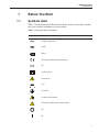
Hart Scientific
9135
Infrared Thermometer Calibrator
User’s Guide
Rev. 5A2604
Fluke Corporation, Hart Scientific Division
799 E. Utah Valley Drive • American Fork, UT 84003-9775 • USA
Phone: +1.801.763.1600 • Telefax: +1.801.763.1010
E-mail: [email protected]
www.hartscientific.com
Subject to change without notice. • Copyright © 2005 • Printed in USA
Rev. 5A2604
Table of Contents
1 Before You Start . . . . . . . . . . . . . . . . . . . . . . . . . . 1
1.1
1.2
Symbols Used . . . . . . . . . . . . . . . . . . . . . . . . . . . . 1
Safety Information . . . . . . . . . . . . . . . . . . . . . . . . . . 2
1.2.1
1.2.2
1.3
Warnings . . . . . . . . . . . . . . . . . . . . . . . . . . . . . . . . . . . . . 2
Cautions . . . . . . . . . . . . . . . . . . . . . . . . . . . . . . . . . . . . . 3
Authorized Service Centers. . . . . . . . . . . . . . . . . . . . . . 3
2 Introduction . . . . . . . . . . . . . . . . . . . . . . . . . . . . 7
3 Specifications and Environmental Conditions . . . . . . . . . . 9
3.1
3.2
Specifications . . . . . . . . . . . . . . . . . . . . . . . . . . . . . 9
Environmental Conditions . . . . . . . . . . . . . . . . . . . . . . 9
3.3
Warranty . . . . . . . . . . . . . . . . . . . . . . . . . . . . . . . 10
4 Quick Start . . . . . . . . . . . . . . . . . . . . . . . . . . . . 11
4.1
4.2
Unpacking . . . . . . . . . . . . . . . . . . . . . . . . . . . . . . 11
Set-up . . . . . . . . . . . . . . . . . . . . . . . . . . . . . . . . 11
4.3
Power . . . . . . . . . . . . . . . . . . . . . . . . . . . . . . . . 11
5 Parts and Controls . . . . . . . . . . . . . . . . . . . . . . . . 13
5.1
Back Panel. . . . . . . . . . . . . . . . . . . . . . . . . . . . . . 13
5.2
5.3
Bottom. . . . . . . . . . . . . . . . . . . . . . . . . . . . . . . . 13
Top Panel . . . . . . . . . . . . . . . . . . . . . . . . . . . . . . 13
5.4
Right Side Panel . . . . . . . . . . . . . . . . . . . . . . . . . . . 14
6 General Operation . . . . . . . . . . . . . . . . . . . . . . . . 17
6.1
6.2
6.3
Set-up . . . . . . . . . . . . . . . . . . . . . . . . . . . . . . . . 17
Setting the Temperature . . . . . . . . . . . . . . . . . . . . . . . 17
Target Ready Indicator . . . . . . . . . . . . . . . . . . . . . . . 17
7 Controller Operation . . . . . . . . . . . . . . . . . . . . . . . 19
8 Thermometer Calibration . . . . . . . . . . . . . . . . . . . . 21
8.1
8.2
IR Thermometer Calibration . . . . . . . . . . . . . . . . . . . . 21
RTD Calibration . . . . . . . . . . . . . . . . . . . . . . . . . . . 21
i
9 Calibration Procedure . . . . . . . . . . . . . . . . . . . . . . 23
10 Maintenance . . . . . . . . . . . . . . . . . . . . . . . . . . . 25
11 Troubleshooting. . . . . . . . . . . . . . . . . . . . . . . . . . 27
11.1
CE Comments . . . . . . . . . . . . . . . . . . . . . . . . . . . . 27
11.1.1
11.1.2
ii
EMC Directive . . . . . . . . . . . . . . . . . . . . . . . . . . . . . . . . . 27
Low Voltage Directive (Safety) . . . . . . . . . . . . . . . . . . . . . . . . . 27
1 Before You Start
Symbols Used
1
1.1
Before You Start
Symbols Used
Table 1 lists the International Electrical Symbols. Some or all of these symbols
may be used on the instrument or in this manual.
Table 1 International Electrical Symbols
Symbol
Description
AC (Alternating Current)
AC-DC
Battery
CE Complies with European Union Directives
DC
Double Insulated
Electric Shock
Fuse
PE Ground
Hot Surface (Burn Hazard)
Read the User’s Manual (Important Information)
Off
On
1
9135 Infrared Thermometer Calibrator
User’s Guide
Symbol
Description
Canadian Standards Association
OVERVOLTAGE (Installation) CATEGORY II, Pollution Degree 2 per IEC1010-1 refers to the level of Impulse Withstand Voltage protection provided. Equipment of
OVERVOLTAGE CATEGORY II is energy-consuming equipment to be supplied from
the fixed installation. Examples include household, office, and laboratory appliances.
C-TIC Australian EMC Mark
The European Waste Electrical and Electronic Equipment (WEEE) Directive
(2002/96/EC) mark.
1.2
Safety Information
Use this instrument only as specified in this manual. Otherwise, the protection
provided by the instrument may be impaired.
The following definitions apply to the terms “Warning” and “Caution”.
• “Warning” identifies conditions and actions that may pose hazards to the
user.
• “Caution” identifies conditions and actions that may damage the instrument being used.
1.2.1
Warnings
To avoid personal injury, follow these guidelines.
• DO NOT operate this unit without a properly grounded, properly polarized power cord.
• DO NOT connect this unit to a non-grounded, non-polarized outlet.
• DO NOT use this unit for any application other than calibration work.
• DO NOT use this unit in environments other than those listed in the
user’s guide.
• Completely unattended operation is not recommended for safety reasons.
• Always replace the fuse with one of the same rating, voltage and type.
• If the instrument is used in a manner not in accordance with the equipment design, the operation of the calibrator may be impaired or safety
hazards may arise.
• Follow all safety guidelines listed in the user’s manual.
• DO NOT operate near flammable materials.
• DO NOT use fluids to clean the plate.
2
1 Before You Start
Authorized Service Centers
• The instrument can generate high temperatures. Precautions must be
taken to prevent personal injury or damage to objects. Probes may be very
hot when removed from the instrument. Cautiously handle probes to prevent personal injury. Carefully place probes on a heat resistant surface or
rack until they are at room temperature. Never place any objects other
than the probe to be calibrated into the plate.
• Calibration Equipment should only be used by Trained Personnel.
1.2.2
Cautions
To avoid possible damage to the instrument, follow these guidelines.
• Never introduce fluids or any foreign material onto the IR target or
into the well block.
• DO NOT change the values of the calibration constants from the factory
set values. The correct setting of these parameters is important to the
safety and proper operation of the calibrator.
• ONLY OPERATE this unit with proper supply voltage and frequency.
Make sure both of the voltage switches are set properly. Operating this instrument with the wrong supply voltage or switch settings can damage the
instrument and has the potential to start a fire.
• Operate the instrument in room temperatures between 5-40°C (41-104°F).
Allow sufficient air circulation by leaving at least three inches of space
between the instrument and nearby objects.
• This is a precision instrument. Although it has been designed for optimum
durability and trouble free operation, it must be handled with care. The instrument should not be operated in excessively wet, oily, dusty, or dirty
environments. It is important to keep the plate of the instrument clean and
clear of any foreign matter.
• If a mains supply power fluctuation occurs, immediately turn off the instrument. Severe power disturbances from brownouts and blackouts could
damage the instrument. Wait until the power has stabilized before re-energizing the instrument.
• The calibrator is equipped with an internal electrical fuse. If a fuse blows,
it is likely caused by failure of another part. If this occurs, the calibrator
should be returned for inspection. Contact a Hart Scientific Authorized
Service Center for assistance.
1.3
Authorized Service Centers
Please contact one of the following authorized Service Centers to coordinate
service on your Hart product:
Fluke Corporation, Hart Scientific Division
799 E. Utah Valley Drive
3
9135 Infrared Thermometer Calibrator
User’s Guide
American Fork, UT 84003-9775
USA
Phone: +1.801.763.1600
Telefax: +1.801.763.1010
E-mail: [email protected]
Fluke Nederland B.V.
Customer Support Services
Science Park Eindhoven 5108
5692 EC Son
NETHERLANDS
Phone: +31-402-675300
Telefax: +31-402-675321
E-mail: [email protected]
Fluke Int'l Corporation
Service Center - Instrimpex
Room 2301 Sciteck Tower
22 Jianguomenwai Dajie
Chao Yang District
Beijing 100004, PRC
CHINA
Phone: +86-10-6-512-3436
Telefax: +86-10-6-512-3437
E-mail: [email protected]
Fluke South East Asia Pte Ltd.
Fluke ASEAN Regional Office
Service Center
60 Alexandra Terrace #03-16
The Comtech (Lobby D)
118502
SINGAPORE
Phone: +65 6799-5588
4
1 Before You Start
Authorized Service Centers
Telefax: +65 6799-5588
E-mail: [email protected]
When contacting these Service Centers for support, please have the following
information available:
• Model Number
• Serial Number
• Voltage
• Complete description of the problem
5
2 Introduction
2
Introduction
Hart Scientific’s Model 9135 Infrared Thermometer Calibrator is a small, portable instrument designed for quick on-site checks and calibration of infrared
thermometers. It features an aluminum temperature-controlled plate coated
with special 0.95 emmisivity paint. A precision proportional-integral temperature controller maintains the temperature of the plate. The set-point can be conveniently selected by the one-button control to 50°C, 100°C, or 150°C. One of
three yellow LEDs corresponding to the three set-points glows to indicate
which set-point is selected. A green LED turns on when the temperature of the
plate reaches the set-point temperature and is stable. The 9135 calibrator was
designed for portability, low cost, speed, and ease of operation.
7
3 Specifications and Environmental Conditions
Specifications
3
Specifications and Environmental
Conditions
3.1
3.2
Specifications
Set-points
50°C (122°F), 100°C (212°F), and 150°C (302°F)
Accuracy
±1.0°C
Stability (2-sigma)
±0.1°C (±0.18°F)
Target Emmisivity
0.95
Target Area
1.5 in. (38 mm) diameter
Test Well Size
0.125 in. (3.18 mm) diameter
Heating Time
25 to 150°C: 3 minutes typical
Stabilization Time
3 minutes typical
Cooling Time
150 to 50°C: 25 minutes typical
Power
115 VAC (±10%), 1.0 A, or 230 VAC (±10%), 0.5 A, 50/60 Hz, 125 W.
Size
1.8" (46 mm) H x 4.4" (112 mm) W x 7.8" (198 mm) D
Weight
1.5 lb. (0.7 kg)
Safety
OVERVOLTAGE (Installation) CATEGORY II, Pollution Degree 2 per
IEC1010-1
Environmental Conditions
Although the instrument has been designed for optimum durability and trouble-free operation, it must be handled with care. The instrument should not be
operated in an excessively dusty or dirty environment. Maintenance and cleaning recommendations can be found in the Maintenance section of this manual.
The instrument operates safely under the following conditions:
• temperature range: 5-40°C (41-104°F)
• ambient relative humidity: maximum 80% for temperature <31°C, decreasing linearly to 50% at 40°C
• pressure: 75kPa-106kPa
• mains voltage within ±10% of nominal
• vibrations in the calibration environment should be minimized
• altitude less than 2,000 meters
9
9135 Infrared Thermometer Calibrator
User’s Guide
3.3
Warranty
Fluke Corporation, Hart Scientific Division (Hart) warrants this product to be
free from defects in material and workmanship under normal use and service
for a period as stated in our current product catalog from the date of shipment.
This warranty extends only to the original purchaser and shall not apply to any
product which, in Hart’s sole opinion, has been subject to misuse, alteration,
abuse or abnormal conditions of operation or handling.
To exercise this warranty, the purchaser must forward the product after calling
or writing a Hart Scientific Authorized Service Center (see Section 1.3) for authorization. The Service Centers assume NO risk for in-transit damage.
THE FOREGOING WARRANTY IS PURCHASER’S SOLE AND EXCLUSIVE REMEDY AND IS IN LIEU OF ALL OTHER WARRANTIES, EXPRESS OR IMPLIED, INCLUDING BUT NOT LIMITED TO ANY
IMPLIED WARRANTY OR MERCHANTABILITY, OR FITNESS FOR ANY
PARTICULAR PURPOSE OR USE. HART SHALL NOT BE LIABLE FOR
ANY SPECIAL, INDIRECT, INCIDENTAL, OR CONSEQUENTIAL DAMAGES OR LOSS WHETHER IN CONTRACT, TORT, OR OTHERWISE.
10
4 Quick Start
Unpacking
4
4.1
Quick Start
Unpacking
Unpack the calibrator carefully and inspect it for any damage that may have occurred during shipment. If there is shipping damage, notify the carrier immediately. Verify that the following components are present:
• 9135 Calibrator
• Manual
• Report of Calibration
• Calibration Label
4.2
Set-up
Place the calibrator on a flat surface with at least three inches of free space
around the instrument. The prop may be swung down to tilt the instrument
from a horizontal position. Plug the power cord into a grounded mains outlet of
the proper voltage (see Section 4.3). Observe that the nominal voltage corresponds to that indicated on the back of the calibrator.
Turn on the power to the calibrator by toggling the power switch on. The yellow LED corresponding to the 50°C set-point should immediately illuminate
and the calibrator should begin heating to 50°C. If the unit fails to operate
please check the power connection.
4.3
Power
The calibrator is configured for either 115 VAC (±10%), 50/60 Hz or 230 VAC
(±10%), 50/60 Hz using switches underneath. There are two switches and both
must be set to the correct voltage. One switch configures the power supply and
the other configures the heater. The calibrator can be switched in the field for
operation at either voltage as long as the following conditions are observed:
• The supply voltage must always match the switch settings! Operating this
instrument with the wrong supply voltage or switch settings will likely
damage the instrument and has the potential to start a fire.
• Both voltage switches must be set properly. Again, operating this instrument with the wrong supply voltage or switch settings will likely damage
the instrument and has the potential to start a fire.
• Always unplug the instrument before changing the voltage settings!
Changing the voltage switches with power applied will likely damage the
instrument and has the potential to start a fire.
Use a small slotted-type screwdriver or equivalent instrument to change the
switches.
11
9135 Infrared Thermometer Calibrator
User’s Guide
The mains supply must be reasonably stable and free from surges, dropouts,
and interference that can affect the temperature stability of the IR target.
12
5 Parts and Controls
Back Panel
5
Parts and Controls
The user should become familiar with the 9135 calibrator and its parts. Refer to
Figures 1 and 2 as you read the following sections.
5.1
Back Panel
Power Cord - The power cord attaches to the back of the instrument. It plugs
into a standard 115 VAC (optional 230 VAC) grounded socket.
Power Switch - The power switch is located on the back panel of the calibrator. The switch is either on or off. The on position is for normal operation. The
off position disconnects power to the entire unit.
5.2
Bottom
Prop - The prop is located on the bottom of the 9135 and lays flat against the
bottom of the calibrator when not in use. It can be swung down to incline the
instrument.
Supply Voltage Switches - These switches are set to 115V or 230V depending
on the supply voltage (Section 4.3).
5.3
Top Panel
The top panel is illustrated in Figure 1.
IR Target - The large hole in the top panel gives access to the IR target. The IR
target is a metal plate that is coated with a special paint with an emmisivity of
0.95. The IR target is controlled at the selected set-point.
Set-point Select - The button on the top panel is used to select one of the three
set-points. Pressing the button selects the next set-point in the order
50°C-100°C-150°C then back to 50°C. The LED corresponding to the selected
set-point will light.
Set-point Indicators - The three yellow LEDs on the top panel correspond to
the three set-points. When the power is on one LED will glow indicating which
set-point is currently selected.
Target Ready Indicator - The green LED shows when the temperature of the
IR target is reached and is stable. Immediately after the power is switched on or
a new set-point is selected the ready indicator will be dark. It will light up when
the temperature has stabilized at the set-point. This indicates the instrument is
now ready to be used for calibration.
13
9135 Infrared Thermometer Calibrator
User’s Guide
Power Cord Socket
Power Switch
INFRARED CALIBRATOR
: HOT SUR
ION
FA
UT
RFACE
SU
SU
OT
:H
UTION: HO
CA
T
ACE CAUTIO
RF
N
Target Ready
Indicator
IR Target
CE
CA
9135
150°C
302°F
TARGET READY
100°C
212°F
Set-point
Indicators
50°C
122°F
Set-point
Select
SET-POINT SELECT
Figure 1 Top Panel
5.4
Right Side Panel
The right side panel is illustrated in Figure 2.
Test Well - The right side panel has a 6.3 mm (0.25") hole near its center that
allows access to a 3.18 mm (0.125") test well in the IR target plate. The test
well accepts 3.18 mm (0.125") RTDs, thermistor probes, or thermocouples for
calibration (see Section 8.2). The test well is also used to calibrate the 9135
against a standard RTD (see Section 9).
Calibration Access Hole - There is a small oblong hole on the right side panel.
These gives access to two potentiometers used to calibrate the 9135. DO NOT
14
5 Parts and Controls
Right Side Panel
adjust these potentiometers unless qualified to do so as part of a regular maintenance and calibration schedule (see Section 9).
Calibration
Access Hole
Test Well
Prop
Figure 2 Right Side Panel
15
6 General Operation
Set-up
6
General Operation
This section explains basic operation of the 9135 calibrator.
6.1
Set-up
Place the calibrator on a flat surface with at least three inches of free space
around the instrument. The prop may be swung down to tilt the instrument
from a horizontal position. Plug the power cord into a grounded mains outlet.
Make sure the supply voltage and voltage switch settings are correct (see Section 4.3). The supply voltage must always match the switch settings! Operating
this instrument with the wrong supply voltage or switch settings will likely
damage the instrument and has the potential to start a fire.
Turn on the power to the calibrator by toggling the power switch on. The yellow LED corresponding to the 50°C set-point should immediately illuminate
and the calibrator will begin heating to this set-point. If the unit fails to operate
please check the power connection. The green ready LED should initially be
dark until the IR target reaches the set-point.
6.2
Setting the Temperature
As soon as the 9135 calibrator is switched on, the 50°C set-point LED lights
and the instrument begins to heat to 50°C. If this set-point is desired, wait until
the temperature stabilizes. To select the 100°C set-point press the select button
once and observe the 100°C set-point LED light up. To select the 150°C
set-point press the select button once more and observe the 150°C set-point
LED light up. To set the set-point back to 50°C press the select button once or
twice until the 50°C set-point LED lights up. Any time the select button is
pressed the green ready LED will go dark and stay dark until the temperature
reaches the new set-point. After the set-point is selected it will take some time
for the instrument to heat or cool to the desired temperature. Wait for the green
ready indicator to light up before proceeding with any calibrations.
6.3
Target Ready Indicator
The green target ready indicator shows when the IR target has stabilized to the
set-point. Immediately after the power is switched on and any time the select
button is pressed to change the set-point, the green LED will go dark and stay
dark until the temperature reaches the new set-point. After setting the set-point
it can take up to ten minutes to heat up to and stabilize at a higher temperature
and up to 40 minutes to cool down to and to stabilize at a lower temperature.
When the set-point is reached and the temperature becomes stable the green
ready LED will light indicating that the target is ready for calibration.
17
7 Controller Operation
7
Controller Operation
The 9135 calibrator uses a precise analog proportional-integral controller that
maintains the temperature of the IR target. The set-point is controlled by a special digital switching circuit that allows one button to advance through the sequence of set-points. It also contains a power on reset circuit that causes the
controller to default to the first set-point immediately after the power is
switched on. The controller senses the temperature of the IR target using a
thermistor sensor imbedded in the plate. It compares the resistance of the
thermistor to preset set-point resistances to determine whether the IR target
should be heated or cooled and how much power should be applied. The controller uses a solid-state relay circuit to apply power in a time-proportioned
manner to a resistance heater attached to the IR target. The ready indicator circuit uses the difference signal between the temperature sensor and the set-point
to determine whether temperature stability has been achieved or not and
switches the ready LED on or off accordingly.
19
8 Thermometer Calibration
IR Thermometer Calibration
8
Thermometer Calibration
The 9135 calibrator was designed primarily for calibrating infrared thermometers. However, it can also be used to calibrate certain types of RTDs. The following sections explain the calibration of IR thermometers and RTDs
respectively.
8.1
IR Thermometer Calibration
Infrared thermometers are calibrated by pointing them at the 9135’s IR target
and comparing their readings to the known temperature of the target. In order
to achieve accurate measurements several important conditions must be
observed:
• The IR target must first reach the desired temperature and be stable. The
green ready LED lights up when the IR target is ready for calibration. DO
NOT attempt to calibrate thermometers unless the green ready LED is lit,
otherwise accuracy may be compromised.
• The 9135’s IR target is specially coated for an emmisivity of 0.95. The
9135 should only be used to calibrate IR thermometers that are set for this
value of emmisivity. DO NOT attempt to calibrate thermometers unless
they are set for 0.95 emmisivity, otherwise accuracy may be compromised.
• When calibrating IR thermometers the thermometer must “see” only the
IR target of the 9135. The thermometer must be pointed directly at the target at approximately a 90° angle and with a close enough proximity that
the target area of the thermometer is completely contained within the IR
target of the 9135. This may depend on the particular IR thermometer being used. DO NOT attempt to calibrate a thermometer unless it is close
enough to ensure that its target area falls entirely within the IR target of
the 9135, otherwise accuracy may be compromised.
• Remember that the IR target gets hot! Be careful not to touch the IR
target or let any object come into contact with it. The IR target must be
kept clean (see Section 10).
8.2
RTD Calibration
The IR target plate of the 9135 has a 3.18 mm. (0.125") hole in it that can be
used to calibrate appropriately sized RTDs as well as thermistors and
thermocouples. Access to the well is through a 6.3 mm. (0.25") hole near the
center of the right side panel. Please observe the following points when calibrating RTDs and other probes:
• The IR target plate must first reach the desired temperature and be stable.
The green ready LED lights up when the IR target plate is ready for cali-
21
9135 Infrared Thermometer Calibrator
User’s Guide
bration. DO NOT attempt to calibrate thermometers unless the green
ready LED is lit, otherwise accuracy may be compromised.
• The 9135’s test well is intended for 3.18 mm. (0.125") diameter probes
only. DO NOT attempt to force probes larger than this size or bent probes
into the well. For good accuracy the probe must be inserted the full depth
of the well and not fit too loosely. DO NOT attempt to calibrate thermometers that are too short or too loose, otherwise accuracy may be compromised.
• The test well must be kept clean and dry. Dirt, oil, or objects stuck in the
well can affect the safety and operation of the 9135 and especially affect
the ability to calibrate the instrument in the future. DO NOT attempt to
insert fluid, grease, or any objects other than clean thermometers into the
well.
• Inserting a probe into the test well may temporarily disturb the temperature of the target plate. For best results wait at least three minutes after inserting the probe before continuing with the calibration.
• Remember that the IR target gets hot! Be careful not to touch the IR
target or let any object other than the probe being calibrated to come into
contact with it. Probes removed from the test well can be hot and remain
so for several minutes. After removing a probe, place it on a safe heat-resistant surface or holder until it cools down.
22
9 Calibration Procedure
9
Calibration Procedure
The 9135 should be calibrated regularly to ensure accuracy. A one-year or less
calibration interval is recommended. Calibration should only be performed by a
qualified and authorized technician.
The calibration of the 9135 entails adjusting the calibration potentiometers inside the instrument until the temperature of the IR target is close to the
set-point temperature as observed with a calibrated standard RTD at each of the
three set-points. The following are required:
• Standard calibrated RTD or thermistor, 3.18 mm (0.125") diameter and at
least 100 mm (4") sheath length, and a readout device, total uncertainty
0.2°C or better
• Potentiometer adjustment tool
The calibration procedure is as follows:
1. Insert the standard RTD or thermistor fully into the test well of the 9135
through the test well access hole in the right panel.
2. Set the set-point to 50°C and let it stabilize. Wait for the green ready LED to
light.
3. Adjust the potentiometer on the right one-half turn at a time, waiting one to
two minutes between adjustments, until the standard RTD or thermistor shows
the temperature is close to 50°C within 0.2°C. Adjust the potentiometer clockwise to increase the temperature or counter-clockwise to decrease the
temperature.
4. Set the set-point to 150°C and let it stabilize. Wait for the green ready LED
to light.
5. Adjust the potentiometer on the left one-half turn at a time, waiting one to
two minutes between adjustments, until the standard RTD or thermistor shows
the temperature is close to 150°C within 0.2°C. Adjust the potentiometer clockwise to increase the temperature or counter-clockwise to decrease the
temperature.
6. Set the set-point to 100°C and let it stabilize. Wait for the green ready LED
to light.
7. If the standard RTD or thermistor shows the temperature differs from 100°C
by more than 0.5°C but less than 1°C then adjust the potentiometer on the right
one-half turn at a time, waiting one to two minutes between adjustments, until
the standard RTD or thermistor shows the temperature is close to 100°C within
0.25 to 0.5°C. Do not force the temperature to exactly 100°C or the error at the
other two set-points will be excessive. If the temperature differs from 100°C by
more than 1°C then the instrument may require factory service.
8. Check the temperature once more at each of the three set-points.
23
10 Maintenance
10
Maintenance
• This calibration instrument has been designed for a minimum of required
maintenance as long as it is handled with proper care. Please regard the
following:
• Avoid operating the instrument in an oily, wet, dirty, or dusty environment. If the outside of the instrument becomes soiled, it may be wiped
clean with a damp cloth and mild detergent. DO NOT use harsh chemicals on the surface which may damage the paint.
• It is very important to keep the IR target clean. Avoid allowing any objects to contact the surface of the IR target that may contaminate or
scratch it. DO NOT use fluid to clean the IR target. Dust can be blown off
with clean air. When not in use it is advisable to store the calibrator in a
clean covered container.
• The test well must be kept clean and dry. Dirt, oil, or objects stuck in the
well can affect the safety and operation of the 9135 and especially affect
the ability to calibrate the instrument in the future. DO NOT attempt to
insert fluid, grease, or any objects other than clean thermometers into the
well. DO NOT use fluid to clean out the well.
• The calibrator should be handled with care. Avoid knocking, bumping, or
dropping the calibrator. Due to the size and portability of the 9135, it is
vulnerable to being shocked and dropped as it is carried around. It might
be inadvertently dragged off a table top while in use. This can cause permanent damage to the instrument and loss of accuracy.
• If a hazardous material is spilt on or inside the equipment, the user is responsible for taking the appropriate decontamination steps as outlined by
the national safety council with respect to the material.
• If the mains supply cord becomes damaged, replace it immediately.
• Before using any cleaning or decontamination method except those recommended by Hart, users should check with a Hart Scientific Authorized
Service Center to be sure that the proposed method will not damage the
instrument.
• If the instrument is used in a manner not in accordance with the equipment design, the operation of the dry-well may be impaired or safety hazards may arise.
• The 9135 calibrator is calibrated at the factory for optimum performance.
Field adjustment to the instrument should not be attempted. If the unit is
suspected to be out of calibration or in need of repair, please contact the
factory for assistance. The unit should be recalibrated at the factory
yearly. Never attempt to modify the instrument.
25
9135 Infrared Thermometer Calibrator
User’s Guide
WARNING: Never introduce any fluids or other foreign material onto the
IR target or into the well block. This will damage the calibrator, cause loss
of accuracy, and may cause sticking and damage to your probes. In the
event that the calibrator should require service or repair, please contact a
Hart Scientific Authorized Service Center for assistance. The user should
not attempt to make any repairs or adjustments.
26
11 Troubleshooting
CE Comments
11
Troubleshooting
If problems arise while operating the 9135, this section provides some suggestions that may help you solve the problem. If, after considering the following
suggestions, the problem still cannot be resolved, call an Authorized Service
Center for assistance. Opening the unit without contacting an Authorized Service Center may void the warranty.
Problem
Causes and Solutions
Incorrect temperature reading
Check that the green ready LED is lit showing that the IR target has
stabilized to the set-point.
Check that the IR thermometer is close enough to the IR target.
Check that the IR thermometer is set to 0.95 emmisivity.
Check that the IR target surface is clean and free of particles.
Check the temperature with a calibrated 3.18 mm. (0.125") diameter
RTD to verify the temperature of the IR target.
Have the instrument calibrated regularly.
None of the LEDs light
Check that the power cord is plugged in and the power switch is on.
Check that the mains supply is the correct voltage as indicated on the
back of the calibrator.
The internal fuse may be blown or the calibrator may be damaged in
which case the instrument should be returned. Contact a Hart Scientific Authorized Service Center for assistance.
The ready indicator stays dark
Even under normal circumstances it can take up to ten minutes to
heat up to and stabilize at a higher temperature and up to 40 minutes
to cool down to and stabilize at a lower temperature.
Check that the mains supply is the correct voltage as indicated on the
back of the calibrator.
Make sure the mains supply is reasonably free from surges,
drop-outs, and interference.
11.1
CE Comments
11.1.1
EMC Directive
Hart Scientific’s equipment has been tested to meet the European Electromagnetic Compatibility Directive (EMC Directive, 89/336/EEC). The Declaration
of Conformity for your instrument lists the specific standards to which the unit
was tested.
11.1.2
Low Voltage Directive (Safety)
In order to comply with the European Low Voltage Directive (73/23/EEC),
Hart Scientific equipment has been designed to meet the IEC 1010-1 (EN
61010-1) and IEC 1010-2-010 (EN 61010-2-010) standards.
27