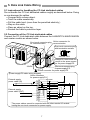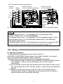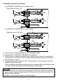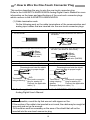
1
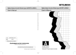
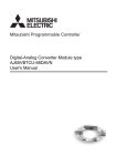
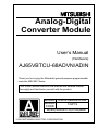
Analog-Digital
Converter Module
User’s Manual
(Hardware)
AJ65VBTCU-68ADVN/ADIN
Thank you for buying the Mitsubishi general-purpose programmable
controller MELSEC Series
Prior to use, please read both this manual and detailed manual
thoroughly and familiarize yourself with the product.
MODEL AJ65V-68ADN-U-HW
MODEL
13JP19
CODE
IB(NA)-0800251-D(0704)MEE
©2003 MITSUBISHI ELECTRIC CORPORATION
z SAFETY PRECAUTIONS z
(Always read before starting use)
When using this equipment, thoroughly read this manual. Also pay careful
attention to safety and handle the module properly.
These precautions apply only to this equipment.
Refer to the user’s manual of the CPU module to use for a description of the PLC
system safety precautions.
These "Safety Precautions" classify the safety precautions into two categories:
"DANGER" and "CAUTION".
DANGER
Procedures which may lead to a dangerous condition and
cause death or serious injury, if not carried out properly.
CAUTION
Procedures which may lead to a dangerous condition and
cause superficial to medium injury, or physical damage
only, if not carried out properly.
Depending on circumstances, procedures indicated by
CAUTION may also
be linked to serious results.
In any case, it is important to follow the directions for usage.
Store this manual in a safe place so that you can take it out and read it whenever
necessary. Always forward it to the end user.
[DESIGN PRECAUTIONS]
DANGER
z When there are communication problems with the data link, the data for the
master module will be held.
Configure an interlocking circuit in a sequence program so that the safety of
the overall system is always maintained.
CAUTION
z Do not bunch the control wires or communication cables with the main circuit
or power wires, or install them close to each other.
They should be installed 100mm (3.9inch) or more from each other.
Not doing so could result in noise that would cause erroneous operation.
A-1
[INSTALLATION PRECAUTIONS]
CAUTION
z Use each module in an environment as specified in the "general
specification" in the detailed manual.
Using the PLC outside the range of the general specifications may result in
electric shock, fire or malfunction, or may damage or degrade the module.
z Securely fix the module to a DIN rail or securely fix it with the CC-Link
connector type fitting.
Not doing so can cause a drop or malfunction.
z Do not touch the conducted area of the module.
Doing so may cause module malfunctioning or breakdowns.
[WIRING PRECAUTIONS]
CAUTION
z Be sure to shut off all phases of the external power supply used by the
system before installation or wiring.
Not doing so can cause the product to be damaged or malfunction.
z Always ground the FG pin and FG1 pin to the protective ground conductor.
Not doing so can cause a malfunction.
z Wire the module correctly after confirming the rated voltage and pin layout of
the product.
Not doing so can cause a fire or failure.
z Do not insert the one-touch connector plug for I/O of the one-touch
connector type/connector type compact remote I/O unit into the one-touch
connector for analog I/O accidentally.
Doing so can cause the module to be damaged.
z Ensure that no foreign matter such as chips and wire-offcuts enter the
module.
Foreign matter can cause a fire, failure or malfunction.
z Always fit a non-wired, one-touch connector plug to the open one-touch
connector for power supply/FG.
Not doing so can cause a failure or malfunction.
z When connecting the wires or cables to the module, always run them in
conduits or clamp them.
Not doing so can damage the module and cables due to loose, moved or
accidentally pulled cables or can cause a malfunction due to a cable
connection fault.
z Do not install the control lines together with the communication cables, or
bring them close to each other. Failure to do so may cause malfunctions due
to noise.
A-2
[WIRING PRECAUTIONS]
CAUTION
z When disconnecting the communication and power supply cables from the
module, do not hold and pull the cable part.
Disconnect the cables after loosening the screws in the portions connected
to the module. Pulling the cables connected to the module can damage the
module and cables or can cause a malfunction due to a cable connection
fault.
[STARTING AND MAINTENANCE PRECAUTIONS]
CAUTION
z Do not touch the pin while the power is on. Doing so may cause malfunction.
z Be sure to shut off all phases of the external power supply used by the
system before cleaning.
Not doing so can cause the module to fail or malfunction.
z Never disassemble or modify the module.
This may cause breakdowns, malfunctioning, injury and/or fire.
z Do not drop the module or give it hard impact since its case is made of resin.
Doing so can damage the module.
z Be sure to shut off all phases of the external power supply used by the
system before mounting or dismounting the module to or from the panel.
Not doing so can cause the module to fail or malfunction.
z Always make sure to touch the grounded metal to discharge the electricity
charged in the body, etc., before touching the module.
Failure to do so may cause a failure or malfunctions of the module.
[DISPOSAL PRECAUTIONS]
CAUTION
z When disposing of this product, treat it as industrial waste.
A-3
Revisions
* The manual number is noted at the lower right of the top cover.
Print Date
Mar., 2003
Jul., 2005
*Manual Number
IB(NA)-0800251-A
IB(NA)-0800251-B
Revision
Sep., 2006
IB(NA)-0800251-C
Partial correction
Chapter 3, Chapter 8
Apr., 2007
IB(NA)-0800251-D
Partial correction
Section 2.1, Section 6.2, Chapter 8
First printing
Partial correction
SAFETY PRECAUTIONS
This manual confers no industrial property rights or any rights of any other kind, nor does it
confer any patent licenses. Mitsubishi electric Corporation cannot be held responsible for
any problems involving industrial property rights which may occur as a result of using the
contents noted in this manual.
© 2003 MITSUBISHI ELECTRIC CORPORATION
A-4
CONTENTS
1. Overview ....................................................................................................... 1
2. Specification ................................................................................................. 1
2.1 Performance specifications ...................................................................... 1
3. Names and setting of parts ........................................................................... 3
4. Loading and Installation ................................................................................ 6
4.1 Precautions when handling ...................................................................... 6
4.2 Installation environment ........................................................................... 6
5. Data Link Cable Wiring ................................................................................. 7
5.1 Instructions for handling the CC-Link dedicated cables............................ 7
5.2 Connection of the CC-Link dedicated cables ........................................... 7
6. Wiring ........................................................................................................... 8
6.1 Wiring precautions ................................................................................... 8
6.2 Module connection example..................................................................... 9
7. How to Wire the One-Touch Connector Plug............................................... 10
8. External Dimension Diagram ...................................................................... 12
A-5
About the Manuals
The following manuals are also related to this product.
Order them if necessary.
Detailed Manual
Manual name
Analog-Digital Converter Module type
AJ65VBTCU-68ADVN/ADIN User’s Manual
Manual No.
(Model code)
SH-080401E
(13JR65)
Related Manual
Manual name
Control & Communication Link System Master/Local
Module type AJ61BT11/A1SJ61BT11 User’s Manual
Control & Communication Link System Master/Local
Module type AJ61QBT11/A1SJ61QBT11 User’s Manual
Control & Communication Link System Master/Local
Module type QJ61BT11N User’s Manual
Manual No.
(Model code)
IB-66721
(13J872)
IB-66722
(13J873)
SH-080394
(13JR64)
Conformation to the EMC Directive and Low Voltage Instruction
When complying with EMC Directives and Low-Voltage Directives by
assembling a Mitsubishi PLC compatible with EMC Directive and Low-Voltage
Directives into the user product, refer to Chapter 3 "EMC Directives and
Low-Voltage Directives" in the User’s Manual (Hardware Section) for the CPU
module being used. The CE logo is printed on the rating plate on the main
body of the PLC that conforms to the EMC directive and low voltage instruction.
To conform this product to the EMC Directive and Low Voltage Directive, refer
to the Section of "CC-Link Modules" in Chapter 3 "EMC Directive and Low
Voltage Directive" of the User's Manual (Hardware) of the CPU module used.
A-6
1. Overview
This user's manual explains the specifications, names and setting of parts, wiring
and others of Type AJ65VBTCU-68ADVN analog-digital converter module
(hereafter abbreviated to the "AJ65VBTCU-68ADVN"), Type
AJ65VBTCU-68ADIN analog-digital converter module (hereafter abbreviated to
the "AJ65VBTCU-68ADIN") which is used as a remote device station of a
CC-Link system.
In this manual, the AJ65VBTCU-68ADVN and AJ65VBTCU-68ADIN are
generically referred to as the AJ65VBTCU-68ADVN/ADIN.
Confirm if the following items are included in the package after unpacking.
Item name
Analog-Digital Converter Module type AJ65VBTCU-68ADVN
Analog-Digital Converter Module type AJ65VBTCU-68ADIN
Number of items
1
1
2. Specification
2.1 Performance specifications
The performance specifications of the AJ65VBTCU-68ADVN/ADIN are shown
below. For general specifications, refer to detailed manual.
Item
Protection class
Analo Voltage
g input
Current
Digital output
I/O characteristics,
maximum resolution,
accuracy (accuracy
relative to maximum
value of digital output
value)
Maximum conversion
speed
Absolute maximum input
Analog input points
CC-Link station type
AJ65VBTCU-68ADVN
AJ65VBTCU-68ADIN
IP1XB
–10 to 0 to +10V DC
(input resistance 1M )
⎯
⎯
0 to +20mA DC
(input resistance 250 )
16-bit signed binary (-96 to +4095)
16-bit signed binary (-4096 to +4095)
Accuracy
Analog input Digital Ambient
Max.
Ambient
range
output temperature temperature Resolution
0 to 55°C
25±5°C
-10 to +10V -4000
User range
to
2.5mV
setting 1 +4000
AJ65VBTCU (-10 to +10V)
-68ADVN
0 to 5V
1.25mV
(Voltage)
1 to 5V
0 to
±0.3%
±0.2%
User range 4000
1.0mV
(±12 digit*) (±8 digit*)
setting 2
(0 to 5V)
0 to 20mA
5µA
AJ65VBTCU 4 to 20mA
0 to
-68ADIN
User range 4000
4µA
(Current)
setting
(0 to 20mA)
* : digit indicates digital value.
1ms/channel.
Voltage ±15 V
current ±30mA
8 channels/module
Remote device station
(Ver.1 remote device station, Ver.2 remote device station)
1
Item
Number of occupied
stations
Communication cable
AJ65VBTCU-68ADVN
AJ65VBTCU-68ADIN
When Ver.1 remote device station (Ver.1-compatible slave station) is set:
3 stations (RX/RY: 32 points each, RWr/RWw: 12 points each)
When Ver.2 remote device station (Ver.2-compatible slave station) is set:
1 station (RX/RY: 32 points each, RWr/RWw: 16 points each)
Ver.1.10 compatible CC-Link dedicated cable:
FANC-110SBH, FA-CBL200PSBH, CS-110
Specific isolated
area
Isolation specifications
Noise durability
External wiring system
One-touch
connector for
communication
One-touch
Applicable connector for
wire size power
supply/FG
Isolation method
Across
communication
system terminals
and all analog input
terminals
Across power supply
system terminals
and all analog input
terminals
Between channels
Photocoupler
isolation
Transformer
isolation
Not isolated
Dielectric
withstand
voltage
Insulation
resistance
5M or higher,
measured with
500VAC for
500VDC
1 minute
insulation
resistance tester
-
-
By noise simulator of 500Vp-p noise voltage, 1µs noise width and 25 to
60Hz noise frequency
One-touch connector for communication [Transmission circuit]
(5 pins pressure welding type, the plug for the connector is sold separately)
One-touch connector for power supply and FG [Unit power supply and FG]
(5 pins pressure welding type, the plug for the connector is sold separately)
One-touch connector for analog I/O
(4 pins pressure welding type, the plug for the connector is sold separately)
<Sold separately>
Online connector for communication: A6CON-LJ5P
Online connector for power supply: A6CON-PWJ5P
Communication line : Ver. 1.10 compatible CC-Link dedicated cable
0.5mm2 (AWG#20) [ 2.2 to 3.0], shielded wire 0.5mm2 (AWG#20)
0.66 to 0.98 mm2 (AWG#18) [ 2.2 to 3.0]
Wire diameter 0.08 mm2 or more
1.0 to 1.4 (A6CON-P214), 1.4 to 2.0 (A6CON-P220)
One-touch
[Applicable cable: 0.14 to 0.2 mm2]
connector for
1.0 to 1.4 (A6CON-P514), 1.4 to 2.0 (A6CON-P520)
analog I/O
[Applicable cable: 0.3 to 0.5 mm2]
TH35-7.5Fe, TH35-7.5Al (conforming to JIS C 2812)
Applicable DIN rail
CC-Link connector type metal installation fitting: A6PLT-J65V1
24VDC (20.4VDC to 26.4VDC, ripple factor within 5%)
External power supply
Inrush current: 4.2A, within 1.2ms
Current consumption 0.10A
Weight
0.17kg
Point
A/D conversion values are fluctuated by self-heating within approx. 30 minutes
after power is turned ON.
2
3. Names and Setting of Parts
The name of each part in the AJ65VBTCU-68ADVN/ADIN is shown.
[Pin layout and signals name]
Pin arrangement
AJ65VBTCU-68AD
N
CON
A
L
I
N
K
CON
B
7)
C
H
1
SEL
3)
POWER
SET
RUN
2
1)
54321
L RUN
3
SW1
CONB
TEST
4
9)
432 1
CON1
1
2
5
4
8
CON2
2)
CON3
OFFSET
ON
6
7
CONA
L ERR
CON4
GAIN
CON5
5) ,6)
8
CON7
MODE
4)
8)
CON6
CON8
CON
C P
O
W
E
CON R
D
5 4 3 21
CONC
COND
A module view
from the top
10)
Pin No.
1
2
CONA,B 3
4
5
1
2
CON1
3
4
1
2
CON2
3
4
1
2
CON3
3
4
1
2
CON4
3
4
1
2
CON5
3
4
1
2
CON6
3
4
1
2
CON7
3
4
1
2
CON8
3
4
1
2
CONC,D
3
3
4
5
Signal name
DA
DB
DG
NC
SLD
CH1 V+/I+
CH1 V-/INC
SLD
CH2 V+/I+
CH2 V-/INC
SLD
CH3 V+/I+
CH3 V-/INC
SLD
CH4 V+/I+
CH4 V-/INC
SLD
CH5 V+/I+
CH5 V-/INC
SLD
CH6 V+/I+
CH6 V-/INC
SLD
CH7 V+/I+
CH7 V-/INC
SLD
CH8 V+/I+
CH8 V-/INC
SLD
FG
+24V
(UNIT)
24G (UNIT)
AG
FG1
No.
Name and
appearance
Description
ON : Power supply on
OFF : Power supply off
On
: Normal operation
Flickering : 0.1s intervals :Input range setting error, mode select
switch setting error. This module is
used as the Ver.2 remote device
station (Ver.2 compatible slave
station) when the network
Normal
parameter mode is set to remote
mode
network Ver.1 mode.
0.5s intervals:Average value setting (count) time
error. Mode select switch setting is
changed after power-on.
RUN
Off
: 24VDC power supply shutoff or watchdog timer
error occurred.
On
: Indicates that the SELECT/SET switch is in the SET
position.
Flickering : 0.1s intervals :Mode select switch setting error
Test
0.5s intervals :An attempt was made to make
setting outside the setting range at
mode
the time of offset/gain setting.
Off
: Indicates that the SELECT/SET switch is in the
SELECT or center position.
On : Normal communication
L RUN
Off : Communication cutoff (time expiration error)
On : Indicates that transmission speed setting or station number
setting is outside the range.
Flicker at fixed intervals : Indicates that transmission speed setting or
station number setting was changed from
that at power-on.
L ERR.
Flicker at unfixed intervals : Indicates that you forgot fitting the
termination resistor or the module or
CC-Link dedicated cable is affected by
noise.
Off : Indicates normal communications.
Normal Normally OFF
TEST
mode
CH
TEST:ON
OFFSET Test
The OFFSET/GAIN/ CH LEDs lit change every time the
GAIN
mode
SELECT/SET switch is moved to SELECT.
POWER
Operation
1) status display
LED
Offset/gain
2) adjusting
LEDs
3)
SELECT/SET
switch
The switch to be used for making the offset/gain settings during test mode.
The switch to be used for selecting the mode among Ver. remote device station
(Ver. -compatible slave station)/Normal mode/Test mode
AJ65VBTCU-68ADVN
AJ65VBTCU-68ADIN
Ver.1 remote 0: Norma mode
Ver.1 remote
0: Norma mode
device station 1: Test mode
device station
1: Test mode
(Ver.1(User range setting 1)
(Ver.1(User range
Mode select
compatible 2: Test mode
compatible
setting)
switch
slave station)
(User range setting 2) slave station)
4)
(Factory-set to
Ver.2 remote 3: Norma mode
Ver.2 remote
3: Norma mode
"0")
device station 4: Test mode
device station
4: Test mode
(Ver.2(User range setting 1)
(Ver.2(User range
compatible 5: Test mode
compatible
setting)
slave station)
(User range setting 2) slave station)
2, 5 to 7: Use
6 to 7: Use prohibited
prohibited
4
No.
Name and
appearance
Description
Transmission
Setting Switches
Speed
4
2
1
Transmission
0
OFF
OFF
OFF
156kbps
speed setting
1
OFF
OFF
ON
625kbps
switches
2
OFF
ON
OFF
2.5Mbps
3
OFF
ON
ON
5.0Mbps
5)
4
ON
OFF
OFF
10Mbps
Always set the transmission speed within the above range.
The switches are all factory-set to OFF.
Making any other setting than the above will result in an error flickering the "L
ERR." LED.
Confirm the transmission speed setting switch numbers on the seal located on
the side face of the connector for analog I/O.
Use the switches in STATION NO. "10", "20" and "40" to set the tens of the station
number.
Use the switches in STATION NO. "1", "2", "4" and "8" to set the units of the
station number.
The switches are all factory-set to OFF.
Always set the station number within the range 1 to 64.
Setting any other number than 1 to 64 will result in an error, flickering the "L ERR."
Station number LED.
setting
You cannot set the same station number to two or more stations.
switches
Tens
Units
Station
Number
40
20
10
8
4
2
1
1
OFF
OFF
OFF
OFF
OFF
OFF
ON
2
OFF
OFF
OFF
OFF
OFF
ON
OFF
3
OFF
OFF
OFF
OFF
OFF
ON
ON
6)
4
OFF
OFF
OFF
OFF
ON
OFF
OFF
ON
STATION NO.
1 2 4 8 10 20 40
ON
B RATE
1 2 4
Set Value
10
11
OFF
OFF
OFF
OFF
ON
ON
OFF
OFF
OFF
OFF
OFF
OFF
OFF
ON
64
ON
ON
OFF
OFF
ON
OFF
OFF
(Example) To set the station number to "32", set the switches as indicated below.
Tens
Units
Station
Number
40
20
10
8
4
2
1
32
OFF
ON
ON
OFF
OFF
ON
OFF
Confirm the station number setting switch numbers on the seal located on the
side face of the connector for analog I/O.
One-touch
A one-touch connector for connection of the communication line
7) connector for
When carrying out wiring, connect two optional one-touch connector plugs for
communication communication at top and bottom.
One-touch
A one-touch connector for connection of the module power supply line and FG.
connector for
When carrying out jumper wiring, connect two optional one-touch connector plugs
8)
power supply
for power supply/FG at top and bottom.
and FG
One-touch
One-touch connector for analog I/O
9) connector for
Connect a one-touch connector plug when wiring.
analog I/O
10) DIN rail hook
Used to mount the module to the DIN rail.
Point
After power-on, do not change the mode select switch setting.
If you change it midway during operation, the setting at power-on is valid.
5
4. Loading and Installation
4.1 Precautions when handling
The following is an explanation of handling precautions of the module.
(1) Because the case of the module is made of resin, be careful not to drop it or
expose it to strong impact.
4.2 Installation environment
Never install the module in the following environments:
(1) Locations where the ambient temperature is outside the range of 0 to 55°C.
(2) Locations where the ambient humidity is outside the range of 10 to 99%RH.
(3) Locations where dew condensation takes place due to sudden temperature
changes.
(4) Locations where there are corrosive and/or combustible gasses.
(5) Locations where there is a high level of conductive power (such as dust and
iron filings, oil mist, salt, and organic solvents).
(6) Locations exposed to the direct rays of the sun.
(7) Locations where strong power and magnetic fields are generated.
(8) Locations where vibration and shock are directly transmitted to the main
module.
6
5. Data Link Cable Wiring
5.1 Instructions for handling the CC-Link dedicated cables
Do not handle the CC-Link dedicated cables roughly as described below. Doing
so can damage the cables.
• Compact with a sharp object.
• Twist the cable excessively.
• Pull the cable hard. (more than the permitted elasticity.)
• Step on the cable.
• Place an object on the top.
• Scratch the cable's protective layer.
5.2 Connection of the CC-Link dedicated cables
Connect the CC-Link dedicated cable between the AJ65VBTCU-68ADVN/ADIN
and master module as shown below.
One-touch connector plug Online connector for
communication
for communication
5 4 3 2 1
5432 1
One-touch connector plug
with termination resistor
A6CON-TR11
Always fit a non-wired connector to the open connector for power supply/FG.
24VDC
One-touch connector plug
for power supply/FG
Online connector for power supply/FG
[Power supply/FG cable wiring diagram]
Online connector
for power supply/FG
External supply
CONC
1
power cable (IN)
1 FG
2
3
4
5
External supply
power cable (OUT)
2 +24V (UNIT)
3 24G (UNIT)
4 AG
5 FG1
COND
1 FG
2 +24V (UNIT)
3 24G (UNIT)
4 AG
5 FG1
1
2
3
4
5
* The power cables cannot be conected with the other remote I/O module
having the one-touch connector for power supply.
7
[CC-Link dedicated cable wiring diagram]
Online connector
Terminal
Master
for communication
resistor
CONA
module
NC
(Blue)
(White)
(Yellow)
DA
DB
DG
SLD
NC
NC
NC
NC
1
2
3
4
5
1 DA
2 DB
3 DG
4 NC
5 SLD
1
2
3
4
5
CONB
1 DA
2 DB
3 DG
4 NC
5 SLD
Online connector
for communication
1
2
3
4
5
CONA
1 DA
2 DB
3 DG
4 NC
5 SLD
1
2
3
4
5
CONB
1 DA
2 DB
3 DG
4 NC
5 SLD
Terminal
resistor
(A6CONTR11)
Ver.1.10 Compatible CC-Link dedicated cable (FANC-110SBH,CS-110,FA-CBL200PSBH)
FG
Point
• On this unit, use the Ver. 1.10-compatible CC-Link dedicated cable
(FANC-110SBH, CS-110, FA-CBL200PSBH).
You cannot use the Ver. 1.10-compatible CC-Link dedicated cables of other
than the above types, CC-Link dedicated cables and CC-Link dedicated,
high-performance cables.
• The shield cable of the CC-Link dedicated cable should be connected to "SLD"
in each module, and both ends should be grounded through "FG".
6. Wiring
6.1 Wiring precautions
To obtain maximum performance from the functions of
AJ65VBTCU-68ADVN/ADIN and improve the system reliability, an external
wiring with high durability against noise is required.
The precautions when performing external wiring are as follows:
(1) Use separate cables for the AC and AJ65VBTCU-68ADVN/ADIN external
input signals, in order not to be affected by the AC side surge or
conductivity.
(2) Do not bundle or place with load carrying wires other than the main circuit
line, high voltage line or PLC. Noises, surges, or conductivity may affect the
system.
(3) Place a one-point grounding on the PLC side for the shielded line or
shielded cable. However, depending on the external noise conditions, it
may be better have a grounding externally.
8
6.2 Module connection example
(1) AJ65VBTCU-68ADVN (For voltage input)
Signal source 0 to ±10V
*3
*1 shield
CON1 CH.1
1 CH.1 V+
2 CH.1 V3
NC
4
SLD
500k
500k
CON8 CH.8
1 CH.8 V+
2 CH.8 V3
NC
SLD
4
*1 shield
AG
*4
FG1
*3
500k
500k
(2) AJ65VBTCU-68ADIN (For current input)
*2
Signal source 0 to 20mA
CON1 CH.1
1 CH.1 I+
2 CH.1 I3 NC
SLD
4
*1 shield
*1 shield *4
CON8 CH.8
1 CH.8 I+
2 CH.8 INC
3
SLD
4
AG
500k
250
500k
*2
500k
250
500k
FG1
*1: Use a two-core twisted shield line for the power cable.
*2: Indicates the AJ65VBTCU-68ADIN input resistor.
*3: When noise or ripple occurs with the external cable, connect a condenser
with about 0.1 to 0.47µF (25V or higher voltage-resistant product) between
the terminal V+ and V-.
*4: Always perform grounding for FG1. When there is a lot of noise, it may be
better ground AG as well.
If the grounding wiring (grounding yes/no) is changed after the offset and gain
are set, perform the setting of the offset/gain values again.
Point
• Do not insert the one-touch connector plug for I/O of the one-touch connector
type/connector type compact remote I/O unit into the one-touch connector for
analog I/O accidentally.
Doing so can cause the module to be damaged.
9
7. How to Wire the One-Touch Connector Plug
This section describes the way to wire the one-touch connector plug.
Refer to the AJ65VBTCU-68ADVN/ADIN Analog-Digital User’s Manual for more
information on the types and specifications of the one-touch connector plugs
which conform to the AJ65VBTCU-68ADVN/ADIN.
(1) Cable termination work
Do the following work on the cable terminations of the communication and
analog input cables that are inserted into the one-touch connector plugs.
1. Cut the sheath.
Communication Cable Termination Work
2. Separate the shield and drain wire and cut
the shield.
Drain wire
Shield wire
3. Cut the aluminum tape and intervening cord.
4. Straighten out the drain wire and twist it from
the root. (3cm seven or more times)
DA (Blue)
DB (White)
DG (Yellow)
Drain wire
3cm
DA (Blue)
DB (White)
DG (Yellow)
Drain wire (AWG20)
Analog Input Cable Termination Work
Termination using soldering
Termination using crimping sleeves
Disentangle and twist the shield
and cut them to proper length.
V+
Disentangle and twist the shield
and cut them to proper length.
V+
VTermination
using soldering
V-
SLD
One-touch connector
plug for analog I/O
Connect the applicable
cable (*1).
SLD
Termination
One-touch connector
using crimping
plug for analog I/O
sleeves
Connect the applicable
Example: Butt joint cable (*1).
*1: For the applicable cable size, refer to the AJ65VBTCU-68ADVN/ADIN
Analog-Digital User’s Manual.
Point
• Where possible, round the tip that was cut with nippers or like.
If the section of the cable to be inserted is not round, the cable may be caught at
any point and not go far enough.
• Do insulation work as necessary on the area of the shield that will not be
inserted into the one-touch connector plug.
10
(2) Checking the plug cover
Check whether the plug cover is installed in the plug.
Caution:
Plug
Before inserting the cable, do not push the
plug cover into the plug. Once
Plug cover insulation-displaced, the plug cannot be
reused.
(3) Inserting the cable
Lift the back of the plug cover and insert the cable
until it makes contact with the plug.
Insert the signal cables into the one-touch
connector plug as shown below.
<For communication>
<For power supply/FG>
<For analog input>
4 3 2 1
54321
54321
Signal name
Signal name
DA (Blue)
DB (White)
DG (Yellow)
NC
SLD
FG
+24V (UNIT)
24G(UNIT)
AG
FG1
Signal name
V+ / I+
V+ / INC
SLD
Point
• Insert the cables far enough.
Not doing so can cause an insulation displacement fault.
• The cable inserted may come out of the cover front.
At this time, pull it back until the cable tip goes back into the plug cover.
(4) Insulation displacement of plug cover
Using pliers or like, push the plug cover into the plug to
insulation-displace it.
After insulation displacement, make sure that the plug
cover is securely installed in the plug as shown below.
Point
• The plug cover and plug latches may not engage at the time of insulation
displacement, raising the cover. Since the plug cover has not been
insulation-displaced sufficiently in this state, push the cover into the plug until it
is installed securely.
11
8. External Dimension Diagram
[AJ65VBTCU-68ADVN/ADIN]
31 (1.22)*
41 (1.61)
AJ65VBTCU-68AD
67 (2.64)
3.5
(0.14)
16.5
(0.65)
N
C
H
1
57.5 (2.26)
CON
A
L
I
N
K
CON
B
SEL
POWER
SET
2
RUN
L RUN
TEST
1
2
4
8
5
OFFSET
ON
6
GAIN
57.5 (2.26)
4
7
L ERR
DIN rail
SW1
115 (4.53)
3
8
MODE
CON
C
P
O
W
E
CON R
D
*: This section should be 14.5mm (0.57inch) when an online connector is not
installed.
Unit: mm (inch)
12
Warranty
Mitsubishi will not be held liable for damage caused by factors found not to be the cause of
Mitsubishi; machine damage or lost profits caused by faults in the Mitsubishi products;
damage, secondary damage, accident compensation caused by special factors
unpredictable by Mitsubishi; damages to products other than Mitsubishi products; and to
other duties.
For safe use
y This product has been manufactured as a general-purpose part for general industries, and
has not been designed or manufactured to be incorporated in a device or system used in
purposes related to human life.
y Before using the product for special purposes such as nuclear power, electric power,
aerospace, medicine or passenger movement vehicles, consult with Mitsubishi.
y This product has been manufactured under strict quality control. However, when installing
the product where major accidents or losses could occur if the product fails, install
appropriate backup or failsafe functions in the system.
Country/Region Sales office/Tel
Country/Region Sales office/Tel
U.S.A
Mitsubishi Electric Automation Inc.
Hong Kong
Mitsubishi Electric Automation
(Hong Kong) Ltd.
500 Corporate Woods Parkway Vernon
10th Floor, Manulife Tower, 169 Electric
Hills, IL 60061, U.S.A.
Road, North Point, Hong Kong
Tel : +1-847-478-2100
Tel : +852-2887-8870
Brazil
MELCO-TEC Rep. Com.e Assessoria
China
Mitsubishi Electric Automation
Tecnica Ltda.
(Shanghai) Ltd.
Rua Correia Dias, 184,
4/F Zhi Fu Plazz, No.80 Xin Chang Road,
Edificio Paraiso Trade Center-8 andar
Shanghai 200003, China
Paraiso, Sao Paulo, SP Brazil
Tel : +86-21-6120-0808
Tel : +55-11-5908-8331
Taiwan
Setsuyo Enterprise Co., Ltd.
Germany
Mitsubishi Electric Europe B.V. German
6F No.105 Wu-Kung 3rd.Rd, Wu-Ku
Branch
Hsiang, Taipei Hsine, Taiwan
Gothaer Strasse 8 D-40880 Ratingen,
Tel : +886-2-2299-2499
GERMANY
Korea
Mitsubishi Electric Automation Korea
Co., Ltd.
Tel : +49-2102-486-0
1480-6, Gayang-dong, Gangseo-ku
U.K
Mitsubishi Electric Europe B.V. UK
Seoul 157-200, Korea
Branch
Tel : +82-2-3660-9552
Travellers Lane, Hatfield, Hertfordshire.,
Singapore
Mitsubishi Electric Asia Pte, Ltd.
AL10 8XB, U.K.
307 Alexandra Road #05-01/02,
Tel : +44-1707-276100
Mitsubishi Electric Building,
Italy
Mitsubishi Electric Europe B.V. Italian
Singapore 159943
Branch
Tel : +65-6470-2460
Centro Dir. Colleoni, Pal. Perseo-Ingr.2
Thailand
Mitsubishi Electric Automation (Thailand)
Via Paracelso 12, I-20041 Agrate Brianza.,
Co., Ltd.
Milano, Italy
Bang-Chan Industrial Estate No.111
Tel : +39-039-60531
Moo 4, Serithai Rd, T.Kannayao,
Spain
Mitsubishi Electric Europe B.V. Spanish
A.Kannayao, Bangkok 10230 Thailand
Branch
Tel : +66-2-517-1326
Indonesia
P.T. Autoteknindo Sumber Makmur
Carretera de Rubi 76-80,
Muara Karang Selatan, Block A/Utara
E-08190 Sant Cugat del Valles,
No.1 Kav. No.11 Kawasan Industri
Barcelona, Spain
Pergudangan Jakarta - Utara 14440,
Tel : +34-93-565-3131
P.O.Box 5045 Jakarta, 11050 Indonesia
France
Mitsubishi Electric Europe B.V. French
Tel : +62-21-6630833
Branch
India
Messung Systems Pvt, Ltd.
25, Boulevard des Bouvets, F-92741
Electronic Sadan NO:III Unit No15,
Nanterre Cedex, France
M.I.D.C Bhosari, Pune-411026, India
TEL: +33-1-5568-5568
Tel : +91-20-2712-3130
South Africa
Circuit Breaker Industries Ltd.
Australia
Mitsubishi Electric Australia Pty. Ltd.
Private Bag 2016, ZA-1600 Isando,
348 Victoria Road, Rydalmere,
South Africa
N.S.W 2116, Australia
Tel : +27-11-928-2000
Tel : +61-2-9684-7777
HEAD OFFICE : TOKYO BUILDING, 2-7-3 MARUNOUCHI, CHIYODA-KU, TOKYO 100-8310, JAPAN
NAGOYA WORKS : 1-14, YADA-MINAMI 5-CHOME, HIGASHI-KU, NAGOYA, JAPAN
When exported from Japan, this manual does not require application to the Ministry
of Economy, Trade and Industry for service transaction permission.
Specifications subject to change without notice.
Printed in Japan on recycled paper.