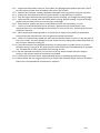
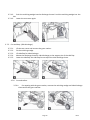
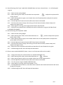
1
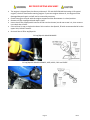
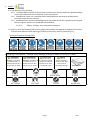
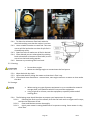
BEFORE STARTING MACHINE! The engine is shipped from the factory without oil. Fill with SAE 15W-40 lubricating oil for petrol engines, check oil level before starting engine. If you start engine without oil, the engine will be damaged beyond repair and will not be covered by warranty. Check the engine oil level with the engine stopped and the lawnmower in a level position. Remove oil filler cap/dipstick and wipe it clean. Insert the oil filler cap/dipstick into the oil filler neck as shown, but do not screw it in, then remove it to check the oil level. If the oil level is near or below the lower limit mark on the dipstick, fill with recommended oil to the upper limit, DO NOT overfill. Re-install the oil filler cap/dipstick. Oil cap/dipstick Model HYM40P Oil cap/dipstick Models HYM43P, 43SP, 46SP, 51SP and 51SPE Page 2 Rev 2 CONTENTS Page No/No’s Section Description PREFACE OIL WARNING 2 1. SAFETY 4-7 2. MACHINE PARTS 8-9 3. ASSEMBLY PROCEDURE 10 - 14 4. OPERATING PROCEDURES 14 - 16 5. MAINTENANCE 17 - 19 6. TROUBLESHOOTING 20 21 - 22 7. SPECIFICATION 8. DISPOSAL of WASTE ELECTRICAL & ELECTRONIC EQUIPMENT 23 9. WARRANTY CONDITIONS 23 10. CONTACT DETAILS 24 11. DECLARATIONS OF CONFORMITY 25 Page 3 Rev 2 1. SAFETY. 1.1. The operator of the machine; 1.1.1. Is responsible for and has a duty of care in making sure that the machine is operated safely and in accordance with the instructions in this user manual. 1.1.2. Should never leave it in a condition which would allow an untrained or unauthorised person/s to operate this machine. 1.1.3. Should take care and show due diligence for the safety of and with regard to those around whilst using the machine, to include but not limited to; 1.1.3.1.1. Elderly, children, pets, livestock and property. 1.2. Some or all of the following PPE, Warning Signs and symbols may appear throughout this manual and you must adhere to their warning/s. Failure to do so may result in personal injury. Personal Protective clothing (PPE) Warning Signs and Symbols – FOLLOW safety messages to avoid or reduce risk of injury or death. DANGER - indicates a hazard which if not avoided could result in serious injury or death. WARNING - indicates CAUTION a - indicates a hazard hazard which if not which if not avoided avoided could result in might result in minor serious injury or death. or moderate injury. Page 4 NOTE - indicates a situation that could easily result in equipment damage. READ MANUAL Rev 2 1.3. Carbon Monoxide. 1.3.1. Carbon monoxide is a colourless and odourless gas, inhaling this gas can cause death as well as serious long term health problems such as brain damage. 1.3.2. The symptoms of carbon monoxide poisoning can include the following; 1.3.2.1. Headaches, dizziness, nausea, breathlessness, collapsing or loss of consciousness. 1.3.2.2. Carbon monoxide symptoms are similar to flu, food poisoning, viral infections and simply tiredness. That’s why it’s quite common for people to mistake this very dangerous poisoning for something else. 1.3.3. To avoid Carbon monoxide poisoning DO NOT Use Petrol/Diesel powered equipment inside a home or garage even if doors and windows are open. 1.3.4. If you think you or someone around you has been affected by carbon monoxide poisoning; 1.3.4.1. Get fresh air immediately. 1.3.4.2. Open doors and windows, turn off machine and leave the affected area. 1.3.4.3. See your doctor immediately or go to hospital - let them know that you suspect carbon monoxide poisoning. 1.3.5. DO NOT use in an enclosed area or a moving vehicle. 1.4. General fuel safety. 1.4.1. Fuel Safety additional information can be obtained from the Health and Safety Executive. 1.4.2. All fuels are Flammable. 1.4.3. Keep away from all ignition sources i.e. Heaters, Lamps, sparks from Grinding or welding. 1.4.4. Hot work on tanks that have contained fuel is extremely dangerous and should not be carried out. 1.4.5. Keep work area clean and tidy. 1.4.6. Clean up all spills promptly using correct methods i.e. absorbent granules and a lidded bin. 1.4.7. Dispose of waste fuels correctly. Page 5 Rev 2 1.5. Battery safety. 1.5.1. Batteries present a risk if they become damage by the possible leaking of electrolyte. This electrolyte is an acid and can cause serious injuries. Care should be taken when working on or near them. 1.5.2. Should you come into contact with acid you should; 1.5.3. Contact medical assistance as soon as possible. 1.5.4. Remove all clothing contaminated with acid. 1.5.5. Use fresh running water to wash excess acid, continue this until medical assistance arrives. 1.5.6. Eye contact with acid needs to be washed away. Make sure that you do not wash the acid to another part of the face or body. 1.5.7. Gasses from charging batteries are highly flammable and great care should be taken to charge in well ventilated areas. 1.6. Petrol safety. 1.6.1.1. Always fuel and defuel in well-ventilated area. 1.6.1.2. Always wear correct, suitable and fit for purpose Personal Protective Equipment (PPE), suggested items are as follows, but are not limited too. 1.6.1.3. Hand protection. 1.6.1.4. Protective clothing. 1.6.1.5. Respiratory protective equipment should be used when in an unventilated area. 1.6.1.6. When defueling always use a propriety fuel retriever. 1.6.1.7. Always carry fuel in the correct and clearly marked container. 1.7. Machine safety. Continual and regular users should monitor closely the condition of their hands with regard to White finger disease or carpal tunnel syndrome. If you think you have been affected seek medical advice immediately. DO NOT modify the unit in any way. Only use the machine for the job for which it is intended. Always remove HT lead from spark plug when checking machine or changing parts. DO NOT operate the equipment when barefoot or wearing open sandals. Recommended PPE but not limited too. Page 6 Rev 2 1.7.1. Inspect machine before each use, and replace any damaged parts before operation. Check for fuel leaks and make sure all fasteners are secure and in place. 1.7.2. Replace parts that are cracked, chipped or damaged in any way before using the machine. 1.7.3. Always use the lawnmower with the grass catcher, or rear deflector in position. 1.7.4. Stop the engine before emptying the grass catcher or before you change the cutting height. 1.7.5. Never put feet or hands near the mower when running. Before mowing, remove all foreign objects from the lawn, which may cause injury or damage. 1.7.6. Keep children, people and pets at a safe distance when the lawnmower is in use. 1.7.7. Use only recommended accessories and parts, approved by the manufacturer. Non approved parts may cause damage to the machine or harm to the user, and will also void your machine’s warranty. 1.7.8. When replacing the cutting blade or any other parts, always use a certified replacement sourced from the manufacturer. Only use genuine Hyundai spare parts. 1.7.9. Under no circumstances should you ever take the product apart or alter it in any way even if the item is faulty. You may damage or cause further harm by taking the product apart and you will void your warranty in doing so. 1.7.10. These lawnmowers are designed exclusively for cutting grass in garden areas in a private domestic setting. Using it for any other purpose other than those intended qualify as improper use. The operator is solely responsible for assuming all risks. 1.7.11. Do not overload the machine. For the first cut of the season always use at the highest setting, it will prevent machine from being overloaded. 1.7.12. The machine will work better when operated within its specified performance range. 1.7.13. Blunt blades will not cut grass efficiently so check blade carefully before each use. If blade is blunt have it sharpened and re-balanced or replace it. Page 7 Rev 2 2. MACHINE PARTS 2.1. Models:- HYM41P, HYM43P, HYM43SP, HYM46SP, HYM51SP and HYM51SPE 1 2 3 Drive lever Operator Presence Control OPC Throttle/Choke lever (On opposite 4 Recoil handle handle on HYM51SPE) 8 9 Spark plug Oil filler cap and dipstick 10 Fuel filler cap 11 Folding handle Side discharge deflector Polyester grass catcher (Models 5 HYM40P, 41P, 43P & HYM43SP) Half plastic box (Models HYM46SP, 51SP & 51SPE) 12 6 Height adjustment lever 13 7 Mower deck 14 Page 8 Primer bulb (Not fitted on HYM51SPE) Exhaust Rev 2 2.2. Model HYM40P only 1 2 3 4 5 6 Operator Presence Control OPC Air filter Oil filler cap and dipstick Mower deck Spark plug Primer bulb Page 9 7 8 9 10 11 Grass catcher Recoil start handle Fuel filler cap Folding handle Exhaust Rev 2 3. ASSEMBLY PROCEDURE 3.1. Remove machine from packaging then; 3.2. Catcher assembly. 3.2.1. On the HYM40P, 41P, 43P and 43SP, insert metal frame. 3.2.2. On lawnmower lift rear cover (2) and clip the grass catcher (1) onto the rear of the mower at point (3). 3.2.3. To remove the grass catcher lift the rear cover (2) and unhook the grass catcher (1). 3.3. Handle assembly. N.B. Locking knobs vary between models) 3.3.1. HYM40P only. 3.3.1.1. Slot handles in base unit (3) and use supplied screws (1) to lock into place. Fold up arms and tighten securing knobs (2) as shown. Page 10 Rev 2 3.3.2. All other models. 3.3.2.1. Clamp the handle to the main body by using the lower clamps (2). 3.3.2.2. Once this is done unfold the upper half of the handle and lock into place using clamps (1). 3.4. Fitting recoil to handle. 3.4.1. Unplug spark plug, pull back the OPC lever 3.4.2. Slowly pull recoil until it reaches the recoil retaining loop on right hand handle. 3.5. Height Adjustment. 3.5.1. HYM40P model only. 3.5.1.1. To adjust the cutting height on the HYM40P model, the wheels can be removed and adjusted manually to one of three settings. 3.5.1.2. Set each wheel to the same height to ensure an even cut. 3.5.2. All other models. 3.5.2.1. Using adjustment lever pull outwards and select required height. 3.5.2.2. Height is automatically adjusted to all wheels. Page 11 Rev 2 3.6. Electric start module for model HYM51SPE only. 3.6.1. Take out the plastic panel (1) from the box. 3.6.2. Remove section (9). 3.6.3. Align the mounting holes on the plastic panel with the mounting holes on the upper-handle (2). 3.6.4. Fix the plastic panel with the bolts and nuts (2) and (4) provided. 3.6.5. Connect the engine cable and battery. 3.6.6. When charging the battery use the charge socket (7) for 6 hours before use. 3.7. 4 in 1 machines. 3.7.1. Functions; 3.7.1.1. Cut and mulch. 3.7.1.2. Cut and drop. (Side discharge). 3.7.1.3. Cut and collect. 3.7.1.4. Cutting and rear discharge. 3.7.2. What is mulching? 3.7.2.1. It is when the grass is cut multiple times it then falls (or is blown) to the ground. 3.7.3. Hints for mulching. 3.7.3.1. Only cut 1/3rd of the growth. 3.7.3.2. Make sure the blade is sharpened regularly. Try not to mow when wet. 3.7.3.3. Set the throttle at maximum. Only mow at walking pace. 3.7.3.4. Regularly clean mulching wedge, underneath of cutter deck and chute. 3.7.4. Fitting the Mulching plug. Make sure the machine is stationary and not running! 3.7.4.1. Lift the rear cover and remove the grass catcher. Page 12 Rev 2 3.7.4.2. Push the mulching wedge into the discharge channel. Lock the mulching wedge into the slot. 3.7.4.3. Lower the rear cover again. 3.7.5. Cut and drop. (Side discharge). 3.7.5.1. 3.7.5.2. 3.7.5.3. 3.7.5.4. 3.7.5.5. Lift the rear cover and remove the grass catcher. Fit the mulching wedge. Lift side flap for side discharge. Mount the discharge chute for side discharge on the support pin of the side flap. Lower the side flap–the side flap lies on top of the side discharge chute. 3.7.6. Cut and collect. 3.7.6.1. For mowing with the grass catcher, remove the mulching wedge and side discharge chute and fit the grass catcher. Page 13 Rev 2 3.7.6.2. Removing the mulching plug: 3.7.6.2.1. Lift rear cover and remove the mulching wedge by unlocking and removing it. 3.7.6.3. Removing the side discharge chute: 3.7.6.3.1. Lift side discharge flap and remove discharge chute. 3.7.6.3.2. The side discharge flap automatically closes the discharge opening on the housing by means of a spring. Regularly clean the side flap and discharge opening from grass and dirt. 4. OPERATING PROCEDURES Always use the lawnmower with the grass catcher, or rear deflector in position. Stop the engine before emptying the grass catcher or before you change the cutting height. Never put feet or hands near the mower when running. Before mowing, remove all foreign objects from the lawn, which may cause injury or damage. Keep children, people and pets at a safe distance when the lawnmower is in use. Always wear correct PPE when using this machine. Recommended PPE but not limited too. Page 14 Rev 2 4.1. Recoil Starting ‘Push Type’ model (N.B. HYM40P does not have a throttle lever – it is a fixed speed engine). 4.1.1. Select correct cutting height. 4.1.2. When starting from cold, turn throttle lever to position and push the primer bulb in fully 5 times. 4.1.3. When starting warm engine, turn throttle lever to half speed position and push the primer bulb in once fully. 4.1.4. Pull the Operator Presence Control (OPC) lever back to the handle. 4.1.5. Pull the recoil starter sharply, do not let go of recoil starter handle, release slowly and repeat until engine starts. 4.1.6. Once engine is running, push engine speed control fully forward. 4.1.7. Pull drive lever towards main handle push machine forward to cut grass. (N.B Not fitted on HYM40P & HYM43P). 4.2. Recoil Starting ‘Self Propelled’ model. 4.2.1. Select correct cutting height. 4.2.2. When starting from cold, turn throttle choke lever to position and push the primer bulb in fully 5 times. 4.2.3. When starting warm engine, turn throttle choke lever to half speed position and push the primer bulb in once fully. 4.2.4. Pull the Operator Presence Control (OPC) lever back to the handle. 4.2.5. Pull the recoil starter sharply, do not let go of recoil starter handle, release slowly and repeat until engine starts. 4.2.6. Move drive lever towards main handle and machine will move forward to cut grass. 4.2.7. N.B Releasing the OPC lever will stop the lawnmower. 4.3. Electric start model HYM51SPE. (Note – there is no fuel primer bulb on this model). 4.3.1. Charge the battery for 6 hours before use. Model HYM51SPE only. 4.3.2. When starting from cold, turn throttle choke lever to position. 4.3.3. When starting warm engine, turn throttle choke lever to half speed position. 4.3.4. Pull the Operator Presence Control (OPC) lever back to the handle. 4.3.5. Turn key to start engine. Model HYM51SPE only. 4.3.6. Once engine is running, select drive speed 1, 2 or 3. 4.3.7. Standing behind the machine, move drive lever towards main handle and machine will move forward to cut grass. 4.3.8. N.B Releasing the OPC lever will stop the lawnmower. Page 15 Rev 2 4.4. Operation. 4.4.1. Do not operate the engine in a confined space where dangerous carbon monoxide fumes can collect. 4.4.2. Mow only in daylight. 4.4.3. Avoid operating the equipment in wet grass, where feasible. 4.4.4. Always be sure of your footing on slopes Walk, never run. 4.4.5. For wheeled rotary machines, mow across the face of slopes, never up and down. 4.4.6. Exercise extreme caution when changing direction on slopes. 4.4.7. Do not mow excessively steep slopes. 4.4.8. Use extreme caution when reversing or pulling the lawn mower towards you. 4.4.9. Stop the blade if the lawn mower has to be tilted for transportation when crossing surfaces other than grass, and when transporting the lawn mower to and from the area to be mowed 4.4.10. Never operate the lawn mower with defective guards, or without safety devices, for example deflectors and/or grass catchers, in place. 4.4.11. Do not change the engine governor settings or over- speed the engine. 4.4.12. Disengage all blade and drive clutches before starting the engine. 4.4.13. Start the engine carefully according to instructions and with feet well away from the blade 4.4.14. Do not tilt the lawn mower when starting the engine. 4.4.15. Do not start the engine when standing in front of the discharge chute. 4.4.16. Do not put hands or feet near or under rotating parts. Keep clear of the discharge opening at all times. 4.4.17. Never pick up or carry a lawn mower while the engine is running. 4.4.18. Stop the engine and disconnect the spark plug cap, make sure that all moving parts have come to a complete stop and, where a key is fitted remove the key. 4.4.18.1. Before clearing blockages or unclogging chute. 4.4.18.2. Before checking, cleaning or working on the lawn mower. 4.4.18.3. After striking a foreign object. Inspect the lawnmower for damage and make repairs before restarting and operating the lawn mower. 4.4.18.4. If lawn mower starts to vibrate abnormally (check immediately). 4.4.18.5. Whenever you leave the lawn mower. 4.4.18.6. Before refuelling. 4.4.19. Reduce the throttle setting during engine shut down. Page 16 Rev 2 5. MAINTENANCE Do not touch rotating blade. Stop the engine and unplug the spark plug before doing any repairs or maintenance. For four stroke engines, check regularly the oil level and add some oil or replace it if necessary. Frequently check the lawnmower and ensure that all grass deposits are removed from beneath the deck. Regularly lubricate the wheel bearings with a suitable lubricant. For security and condition - Check the blade, in order to obtain a good cut, the blade should always be sharp and well balanced. At regular intervals, check the tightness of all nuts, bolts and screws. If the blade hits an obstacle, stop the lawnmower and take it to a service dealer. Refuel in a well-ventilated area with the engine off. Whilst carrying out maintenance you must wear correct PPE, suggested PPE but not limited too; 5.1. The Blade. 5.1.1. The blade is made of pressed steel, in order to obtain a good cut sharpen the blade frequently, around every 25 hours of work. 5.1.2. Be sure that the blade is always well balanced. 5.1.3. To remove the blade, unscrew the bolt, check the blade support and change all spare parts if they are worn out or damaged. 5.2. The Spark Plug. 5.2.1. Spark plug type (or equivalent) F7RTC. 5.2.2. To check spark plug, remove spark plug cap and remove spark plug using the supplied spark plug wrench. 5.2.3. Clean the spark plug electrode also making sure that there is no damage to the insulator or electrode. 5.2.4. The spark plug gap should be 0.70mm to 0.80mm adjust as necessary by carefully bending side electrode. 5.2.5. Install cleaned and adjusted spark plug by hand to avoid cross-threading. 5.2.6. After spark plug seats then tighten as necessary but avoid over-tightening. 5.2.7. Attach spark plug cap. Page 17 Rev 2 Loose spark plugs can overheat and damage engine. A dirty air filter will restrict the air flow to the carburettor, which will reduce engine efficiency. When using the lawnmower in very dusty areas you must clean or replace the air filter more often. Never operate machine without the air filter being fitted it can cause damage to the engine which is not covered by warranty. 5.3. Air Filter. 5.3.1. To gain access to the air filter press the latch tab. 5.3.2. Remove filter, check for contamination and clean as required. 5.3.3. Clean filter by blowing air through it using an air gun not exceeding 30psi. 5.3.4. Never use a brush to clean the filter it will only drive dirt into the fibres of the filter. 5.3.5. Wipe dirt from the air cleaner body by using a moist rag, be careful to prevent dirt or debris entering the air ducts into the carburetor. 5.4. Fuel and Carburettor. Using old or stale fuel will impair starting and running of machine. Make sure that the machine has fresh unleaded fuel and always remove fuel before storing for long periods. Page 18 Rev 2 5.4.1. To drain the carburetor float bowl undo the drain bolt making sure that the washer is not lost. 5.4.2. Use a suitable container to catch fuel. Take care not to spill fuel and make sure that all spilt fuel is cleared away safely. 5.4.3. Open fuel valve to make sure all fuel is drained. 5.4.4. Once drained you can release bowl by undoing bowl release bolt on bottom of float bowl, be sure not to lose the bowl sealing washer. 5.4.5. Remove any remaining fuel from bowl. 5.5. Cleaning. Do not hose engine. Water can damage engine or contaminate the fuel system. 5.5.1. Wipe deck with dry cloth. 5.5.2. Hose under deck by tilting the mower so that the air filter is up. 5.5.3. If fitted with hose attachment - connect hose, start engine and turn on water to clean under the deck. 5.6. Storage. When storing any type of power equipment in an un-ventilated or material storage shed, care should be taken to rust-proof the equipment. Using a light oil or silicone, coat the equipment, especially cables and all moving parts. 5.6.1. The following steps should be taken to prepare your lawnmower for storage: 5.6.1.1. Following the final cut of the season, drain the fuel tank and run engine until it stops, to drain the carburetor of fuel. 5.6.1.2. Clean and lubricate mower thoroughly. 5.6.1.3. Lightly coat mower’s cutting blade with oil to prevent rusting. Store mower in a dry, clean area. Page 19 Rev 2 6. TROUBLESHOOTING. 6.1. Engine Troubleshooting - N.B. Where necessary all corrective actions should be carried out by suitably qualified person/s. 6.2. If the starter rope becomes disconnected from the rope guide on handle, disconnect the spark plug cap. Depress the blade control handle and pull the starter rope out from engine slowly and reengage in guide. Re connect spark plug cap. PROBLEM Engine does not start. PROBABLE CAUSE Throttle lever not in the correct position for the prevailing conditions. Fuel tank is empty. Stale fuel Air filter element is dirty. Spark plug is loose. Spark plug cap loose or disconnected from plug. Spark plug gap is incorrect. Carburetor is flooded with fuel. Faulty ignition module. Engine difficult to start or loses power. Engine operates erratically. Engine idles poorly. Engine skips at high speed. Engine overheats. Mower vibrates abnormally. Dirt, water or stale fuel in tank. Vent hole in fuel tank cap is plugged. Air filter element is dirty. Spark plug is defective. Spark plug gap is incorrect. Air filter element is dirty. Air filter element is dirty. Air slots in engine shroud are blocked. Cooling fins and air passages under engine housing are blocked Gap between electrodes of spark plug is too close. Cooling airflow is restricted. Incorrect spark plug. Cutting assembly is loose. Blade/Cutting assembly is unbalanced. Page 20 CORRECTIVE ACTION Move throttle lever to correct position. Fill tank with fuel. Drain carburettor float bowl. Clean air filter element. Tighten spark plug to 25- 30Nm. Make sure spark plug cap is correctly fitted onto spark plug. Set gap between electrodes at 0.7 to 0.8mm. Remove air filter element and pull starter rope continuously until carburetor clears. Contact the service dealer. Drain fuel and clean tank. Fill tank with clean, fresh fuel. Clean or replace fuel tank cap. Clean air filter element. Fit new, correctly gapped plug. Set gap between electrodes at 0.7 to 0.8mm. Clean air filter element. Clean air filter element. Remove debris from slots. Remove debris from cooling fins and air passages. Set gap between electrodes at 0.7 to 0.8mm. Remove any debris from slots in shroud, blower housing, air passages. Fit new spark plug. Tighten blade. Take to service dealer. Rev 2 7. SPECIFICATION MODEL Engine Type Engine Size - cc Oil Capacity - ml Noise Level - dB (A) Rated Speed - rpm Rated Power - kw CE Compliant Drive Type Start Method Height Adjustments Cutting Height - mm Cutting Width - mm Catcher Type Catcher Volume - L Deck Material Hose Connection Wheel Size - Front - mm Wheel Size - Rear - mm Gross Weight - kg Dry Weight Battery Type Fully Assembled Dimensions H x W x L mm Box Dimensions H x W x L - mm Vibration value m/s2 HYM40P Hyundai OHV 4-Stroke 99 400 96 2800 2 EU11 Hand push Recoil Start 4 individual wheel adjustment 25 to 75 (3 heights) 400 Polyester bag 40 Polypropylene No 150 150 21 18.5 N/A HYM40P-2015 Hyundai OHV 4-Stroke 99 400 96 2800 2 EU11 Hand push Recoil Start 4 individual wheel adjustment 25 to 75 (3 heights) 400 Polyester bag 40 Polypropylene No 150 150 21 18.5 N/A HYM43P Hyundai OHV 4-Stroke 139 600 96 2800 2.5 EU11 Hand push Recoil 1003 x 482 x 1078 1003 x 482 x 1078 1070 x 500 x 1350 370 x 476 x 658 370 x 476 x 658 425 x 512 x 700 4.3 4.3 5.7 Central Adjustment 25 to 75 (6 heights) 410 Polyester bag 55 Treated Steel No 150 200 30 26 N/A Soft grip handle Black engine cover Page 21 Rev 2 MODEL Engine Type Engine Size - cc Oil Capacity - ml Noise Level - dB (A) Rated Speed - rpm Rated Power - kw CE Compliant Drive Type Start Method Height Adjustments Cutting Height - mm Cutting Width - mm Catcher Type Catcher Volume - L Deck Material Hose Connection Wheel Size - Front - mm Wheel Size - Rear - mm Gross Weight - kg Dry Weight HYM46SP Hyundai OHV 4-Stroke 139 600 96 2800 2.5 EU11 Self-propelled Recoil Central Adjustment 25 to 85 (7 heights) 460 Solid lid / polyester bag 70 Treated Steel Yes 200 255 40 32 HYM51SP Hyundai OHV 4-Stroke 173 600 98 2800 3.8 EU11 Self-propelled Recoil Central Adjustment 25 to 85 (7 heights) 508 Solid lid / polyester bag 70 Treated Steel No 200 255 42 36 Battery Type N/A N/A 1250 x 650 x 1540 1250 x 650 x 1540 1108 x 640 x 1650 500 x 570 x 810 520 x 580 x 870 520 x 570 x 910 4.8 7.1 7.1 Fully Assembled Dimensions H x W x L mm Box Dimensions H x W x L - mm Vibration value m/s2 Page 22 HYM51SPE Hyundai OHV 4-Stroke 196 600 98 2800 4.8 EU11 Self-propelled - 3 speed Recoil & Electric Start Central Adjustment 25 to 85 (7 heights) 508 Solid lid / polyester bag 70 Treated Steel Yes 200 300 45 38 SLA 12V 5Ah Maintenance free Rev 2 8. DISPOSAL of WASTE ELECTRICAL & ELECTRONIC EQUIPMENT (W.E.E.E.) DIRECTIVE 8.1. All Electrical and Electronic Equipment (Including batteries) should be disposed of in accordance with Government Waste Electrical and Electronic Equipment Directive (2002/96/EC). 9. WARRANTY CONDITIONS 9.1. The manufacturer warrants the product 24 months* from the date of purchase, from all manufacturers defects. 9.1.1. Domestic Use: 9.1.1.1. 1st Year - Parts and Labour. 9.1.1.2. 2nd Year - Parts Only. 9.1.2. 1-year Limited Warranty, 90-day for hire/rental use providing parts, labour and return carriage. Warranty period is effective as of the date of purchase. 9.2. SEE WARRANTY CARD FOR MORE DETAILS. 9.2.1. The manufacturer will replace at his expense the spare parts, which would be classified as defective. In any case the manufacturer will not accept the reimbursement of the machine (partially or totally) and/or damages and interest direct or indirect. 9.3. The warranty does not cover: 9.3.1. Faults caused by insufficient maintenance. 9.3.2. Abnormal use or damage due to hitting obstructions. The mounting, adjustment and preparation of the machine. Normal wear and tear, parts (belt, blade, blade support, bearings, cables, deflectors, spark plug, air filter, recoil start, battery, wheels etc…) 9.3.3. Freight and packing cost. 9.3.4. Only use genuine Hyundai spare parts. 9.3.5. The manufacturer will refuse any responsibility if the machine was not used for the purpose it was made or if the operator did not use the machine as described in the operators manual. 9.3.6. Read the operators manual carefully before using the lawnmower. 9.3.7. For all spare parts you must specify the model of the mower, the year of manufacture, the serial number of the mower and of the engine. For all spare parts please specify the model and serial numbers where appropriate. Page 23 Rev 2 10. GENPOWER CONTACT DETAILS 10.1. Postal address; Genpower Limited, Isaac Way, Pembroke Dock, Pembrokeshire, SA72 4RW, UK. 10.2. Telephone contact number; Office 10.3. Email contact; Technical 10.4. +44 (0) 1646 687880 [email protected] Web site; www.hyundaipowerequipment.co.uk Page 24 Rev 2 11. DECLARATIONS OF CONFORMITY 11.1. Genpower Ltd confirms that these Hyundai products conform to the following CE Directives; 2006/42/EC Machinery Directive 2004/108/EC EMC Directive 2000/14/EC, Amended by 2005/88/EC Noise Emissions Directive 97/68/EC_2010/26/EC NRMM Emissions Directive 11.2. Page 25 Rev 2 NOTES Page 26 Rev 2 NOTES Page 27 Rev 2 Isaac Way, London Road Pembroke Dock, UNITED KINGDOM, SA72 4RW T: +44 (0) 1646 687 880 F: +44 (0) 1646 686 198 e: [email protected] www.hyundaipowerequipment.co.uk