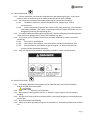
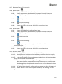
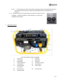
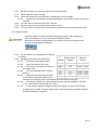
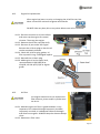
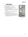
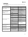
1
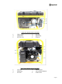
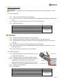
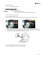
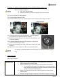
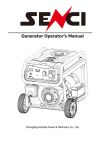
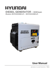
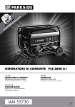
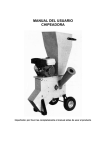
EVO3100 – EVO5000 – EVO7000 – EVO9000E USER MANUAL Model shown EVO9000 BEFORE USE YOU MUST READ THIS MANUAL COMPLETELY – RETAIN FOR FUTURE USE evopower.co.uk CONTENTS Section Description Page No/No’s 1. SAFETY 3-7 2. MACHINE LAYOUT 7-8 3. PRE-OPERATION CHECKS 9 - 10 4. STARTING THE ENGINE - RECOIL 10 5. STARTING THE ENGINE - USING IGNTION KEY 11 6. USING THE MACHINE 11 - 12 7. STOPPING THE ENGINE 13 8. BATTERY 13 9. DISPOSAL of WASTE ELECTRICAL & ELECTRONIC EQUIPMENT (W.E.E.E.) DIRECTIVE 13 10. PERIODIC MAINTENANCE 14 – 18 11. TROUBLESHOOTING 19 12. STORAGE 20 13. SPECICIFATIONS 20 14. CONTACT DETAILS 21 15. DECLARATIONS of CONFORMITY 22 Page 2 1. SAFETY. 1.1. The operator of the machine is; 1.1.1. Responsible for and has a duty of care in making sure that the machine is operated safely and in accordance with the instructions in this user manual. 1.1.2. It should never be left it in a condition which would allow an untrained or unauthorised person/s to operate this machine. 1.1.3. All due care and diligence should be taken by the operator for the safety of and with regard to those around whilst using the machine, to include but not limited to; 1.1.3.1. Elderly, children, pets, livestock and property. 1.2. Some or all of the following PPE, Warning Signs and symbols may appear throughout this manual and you must adhere to their warning/s. Failure to do so may result in personal injury. Personal Protective clothing (PPE) Warning Signs and Symbols Page 3 1.3. Carbon Monoxide 1.3.1. Carbon monoxide is a colourless and odourless gas breathing this gas. It can cause death as well as serious long term health problems such as brain damage. 1.3.2. The symptoms of Carbon monoxide poisoning can include the following; 1.3.2.1. Headaches, Dizziness, Nausea, Breathlessness, Collapsing or Loss of consciousness. 1.3.2.2. Carbon monoxide symptoms are similar to flu, food poisoning, viral infections and simply tiredness. That’s why it’s quite common for people to mistake this very dangerous poisoning for something else. 1.3.3. To avoid Carbon monoxide poisoning DO NOT Use Petrol/Diesel powered equipment inside a home or garage even if doors and windows are open. 1.3.4. If you think you or someone around you has been affected by carbon monoxide poisoning; 1.3.4.1. Get fresh air immediately. 1.3.4.2. Open doors and windows, turn off machine and leave the affected area. 1.3.4.3. See your doctor immediately or go to hospital - let them know that you suspect carbon monoxide poisoning. 1.3.5. Only use Petrol/Diesel powered equipment outside in a well-ventilated area. 1.4. General fuel safety. 1.4.1. Fuel Safety additional information can be obtained from the Health and Safety Executive (HSE) document SR16. 1.4.2. All fuels are Flammable. 1.4.3. Keep away from all ignition sources i.e. Heaters, Lamps, sparks from Grinding or welding. 1.4.4. Hot work on tanks that have contained fuel is extremely dangerous and should not be carried out. 1.4.5. Keep work area clean and tidy. 1.4.6. Clean up all spills promptly using correct methods i.e. absorbent granules and a lidded bin. Page 4 1.4.7. Dispose of waste fuels correctly. 1.4.8. Diesel safety. 1.4.8.1. Always fuel and defuel in well-ventilated area. 1.4.8.2. Always wear correct, suitable and fit for purpose Personal Protective Equipment (PPE), suggested items are as follows, but are not limited too. 1.4.8.3. 1.4.8.4. 1.4.8.5. 1.4.8.6. Hand protection. Protective clothing. When defueling always use a propriety fuel retriever. Always carry fuel in the correct and clearly marked container. 1.4.9. Petrol safety. 1.4.9.1. Always fuel and defuel in well-ventilated area. 1.4.9.2. Always wear correct, suitable and fit for purpose Personal Protective Equipment (PPE), suggested items are as follows, but are not limited too. 1.4.9.3. Hand protection. 1.4.9.4. Protective clothing. 1.4.9.5. Respiratory protective equipment should be used when in an unventilated area. 1.4.9.6. When defueling always use a propriety fuel retriever. 1.4.9.7. Always carry fuel in the correct and clearly marked container. 1.4.10. Electrical Safety. 1.4.10.1. Electricity can kill - never work on LIVE/ENERGISED equipment. 1.4.10.2. Identify electrical isolation method and always isolate all electrical supplies, prior to carrying out any maintenance work. 1.4.10.3. Prior to use and with all electrical supplies isolated check all electrical cables, plugs and connections for the following. 1.4.10.3.1. Are intact and have no signs of damage, to include but not limited to bare wires, chaffing, cuts and loose wiring. If there are any signs of damage, the damaged item should be taken out of service until the damage has been repaired by an electrically competent person. 1.4.10.4. All trailing cables should be routed so as not to cause any kind of trip hazard. 1.4.10.5. Never work on or near electricity with wet hands, wet clothing, and wet gloves. Page 5 1.4.10.6. Batteries present a risk if they become damage by the possible leaking of electrolyte. This electrolyte is an acid and can cause serious injuries. Care should be taken when working on or near them. 1.4.10.6.1. Should you come into contact with acid you should; 1.4.10.6.1.1. Get medical assistance as soon as possible. 1.4.10.6.1.2. Remove all clothing contaminated with acid. 1.4.10.6.1.3. Use fresh running water to wash excess acid, continue this until medical assistance arrives. 1.4.10.6.1.4. Contact with acid needs to be washed away. Make sure that you do not wash the acid to another part of the face or body. 1.4.10.6.1.5. Gasses from charging batteries are highly flammable and great care should be taken to charge in well ventilated areas. 1.5. Additional Safety guidelines’ 1.5.1. Exhaust and Engine 1.5.1.1. The engine and exhaust will become very hot during use do not touch. 1.5.1.2. These items remain hot for some time after use. 1.5.1.3. Place the machine in an area where pedestrians or children are not likely to touch the machine. 1.5.1.4. Avoid placing any flammable materials near the exhaust outlet during operation. 1.5.1.5. Keep the machine at least 1 m from buildings or other equipment, or the engine may overheat. 1.5.1.6. Avoid operating the engine with a dust cover. 1.5.2. Control Functions 1.5.2.1. Oil Warning System 1.5.2.1.1. When the oil falls below the lower level the engine will stop automatically. 1.5.2.1.2. Unless you refill with oil the engine will not start again. 1.5.3. Starter Switch (SW) 1.5.3.1. The engine starter switch controls the ignition. 1.5.3.2. In the ‘OFF’ Position the ignition circuit is switched off and the engine will not run 1.5.3.3. In the ‘ON’ position the engine is ready for starting 1.5.3.4. In the ‘START’ position (pushed against spring tension) the starter motor turns and the machine will start. 1.5.4. AC Switch (Breaker) 1.5.4.1. The AC Switch (Breaker) will turn ‘OFF’ automatically when the load exceeds the generator maximum output. Page 6 1.5.4.2. If AC switch turns ‘OFF’ then before resetting reduce load and keep below the rated output of the machine. Reset and add loads to within working limit of machine. 1.5.5. DO NOT Connect to the generator to mains AC sockets in your building – commonly known as ‘back feeding’ it is extremely dangerous and illegal. 2. MACHINE LAYOUT 1 3 5 7 9 11 13 15 Table One (Model shown EVO5000) Fuel Tank 2 Fuel Cap Fuel Gauge 4 Voltmeter AC Breaker 6 DC Reset Voltage Selector 8 12 Volt DC Outlet 115V Outlet 10 230V Outlet Earth/Ground 12 Power Light Connection Oil Filler Cap 14 Oil Drain Bolt Engine Switch Page 7 1 3 5 Table two (Model shown EVO5000) Choke Lever 2 Air Filter Carburettor 4 Spark Plug Oil Filler Cap 6 Exhaust 1 3 5 Table Three (Model Shown EVO5000) Fuel Tap 2 Recoil Starter Alternator 4 Anti-Vibration Mount Air Filter 6 Choke Lever Page 8 3. PRE-OPERATION CHECKS Pre-operation checks should be carried out each time the generator is used. 3.1. Check engine fuel. 3.1.1. Check fuel level using the fuel level gauge. 3.1.2. If fuel level is low – refill with sufficient fresh unleaded petrol enough to complete the task. 3.1.3. Make sure you use the fuel filter screen on the fuel filler neck. 3.1.4. Fuel tank capacities; Model/s EVO3100 EVO5000 EVO7000 EVO9000E Full 15 Litres 25 Litres 3.1.5. DO NOT refill tank while engine is running or HOT. 3.1.6. Close fuel tap before re-fuelling, see above table for fuel tank capacities. 3.1.7. DO NOT allow any dust, dirt, water or any other foreign objects get into the fuel or fuel tank. 3.1.8. Wipe off any spilt fuel thoroughly before starting the engine. 3.1.9. Keep all sources of ignition and naked flames away from the area in which you are fuelling machine. 3.1.10. Once refuelling is complete close the fuel tap. 3.2. Checking Engine oil 3.2.1. Before checking oil make sure generator is put on stable and level ground. 3.2.2. Remove oil filler cap and check engine oil level 3.2.3. If oil level is below the lower level line, refill with SAE10W/30 or 15W/40, API CH-4/CF/SJ/SL or higher grade to the upper level. N.B. do not screw oil filler in the oil filler cap when checking oil level. 3.2.4. Change contaminated oil. 3.2.5. Oil Capacities Model/s EVO3100 EVO5000 EVO7000 EVO9000E Full 0.6 Litres 1.1 Litres Page 9 3.3. Earthing (Ground). 3.3.1. Always earth the generator. 4. STARTING THE ENGINE - RECOIL Before starting the engine; Turn ‘OFF’ the AC switch. DO NOT connect any electrical appliances to the machine. 4.1. Turn the fuel tap to ‘ON’ position. 4.2. Turn the engine switch to ‘ON’ 4.3. Pull or slide choke lever to the ‘Choke’ position. Not necessary when engine is warm. RUN Position CHOKE Position 4.4. Pull the starter handle slowly until resistance is felt (this is the “Compression” point), pull out swiftly and firmly. Do not fully pull out the rope. After starting, allow the starter handle to return to its original position while still holding the handle. 1.1. Push or slide choke lever back to the 'RUN' position. 1.2. Warm up the engine for a few minutes without load. Page 10 5. STARTING THE ENGINE USING IGNITION KEY (EVO7000/EVO9000L models only) Before starting the engine; Turn ‘OFF’ the AC switch. DO NOT connect any electrical appliances to the machine. 5.1. Turn the fuel tap to ‘ON’ position. 5.2. Turn the engine switch to ‘ON’ 5.3. Slide the choke lever to the ‘Choke’ position. Not necessary when engine is warm. RUN Position CHOKE Position 5.4. Insert key and turn to the start position – hold this against spring tension for approximately 10 seconds. 5.5. Once the machine starts to run release the key and let it rest at the run position. 5.6. If machine does not start after first attempt - wait for 60 seconds and attempt a restart. 5.7. Warm up the engine, then slide choke lever back to the 'RUN' position. 5.8. Continue to warm engine for a few minute without load. The battery is mounted under the control panel - EVO7000/EVO9000L models only 6. USING MACHINE 6.1. Using AC output. Make sure the electrical apparatus to be powered is turned 'OFF' before plugging into socket outlet. Make sure that you do not exceed the rated load of the machine. o To increase the life span of the generator, it is recommended that you do not consistently load the machine and ideally use it at 75% of machines rated capacity. Make sure that the load current is within the rated current of the outlet socket. DO NOT change voltage changeover switch whilst engine is running. Page 11 6.1.1. DO NOT connect any electrical appliances to the machine. 6.1.2. Select required output voltage. 6.1.3. Check the output on the Voltmeter is reading the correct voltage. 6.1.3.1. Display will read output voltage depending on the selection either 115 VAC or 230 VAC 6.1.4. Turn the main AC switch to the 'OFF' position. 6.1.5. Insert the plug into the outlet you are about to use. 6.1.6. Turn the main AC switch to the 'ON' position and turn the electrical appliance ‘ON’. 6.2. Using DC outlet Explosives gases are given off when charging a battery. ONLY charge in a well-ventilated area, away from sparks and naked flames. Exercise care when charging batteries to make sure that the battery does not get overcharged or overheats. 6.2.1. The DC outlet is an unregulated 12 VDC @ 8.3 Amps. % Approximate Specific 6.2.2. Charging instructions for the battery. Charged Voltage Gravity 6.2.2.1. Disconnect the battery leads. 6.2.2.2. Open the battery filler caps. 6.2.2.3. Check that the batteries are full to 100% 13.2 1.255 – 1.275 the upper limit. 75% 9.9 1.215 – 1.235 6.2.2.4. Only use distilled water to fill up 50% 6.6 1.180 – 1.200 battery. 25% 3.3 1.155 - 1.165 6.2.2.5. Measure the specific gravity (SG) 0% 0 1.110 - 1.130 of the battery fluid (electrolyte) and calculate the charging time in accordance with the table to the right. 6.2.2.6. The specific gravity for a fully charged battery shall be between 1.255 and 1.275. You should check the SG every hour. 6.2.2.7. If the battery requires charging connect the battery to the 12 V 8.33 Amp charging outlet. Make sure you observe the correct polarity at the battery. Red to positive and Black to negative. Page 12 7. STOPPING THE ENGINE The AVR can be damaged by stopping the generator under load. ALWAYS remove the load before stopping. 7.1. Turn ‘OFF’ and unplug all appliances attached to the machine. 7.2. Turn the AC switch ‘OFF’. 7.3. Turn the engine switch to the ‘OFF’ position. 7.4. Turn OFF the fuel tap. 8. BATTERY 8.1. The battery is a 12 volt 12Ah sealed lead acid battery and requires no maintenance other than; 8.1.1. Ensure battery terminals are; 8.1.1.1. Kept clean. 8.1.1.2. Kept tight. 8.1.1.3. Covered to prevent short circuiting. 8.1.2. Make sure battery is free from damage and is not leaking. If battery shows signs of damage or leaking – DO NOT continue to use. Instead replace battery immediately. Make sure that all battery acid spills are correctly cleaned up straight away. 8.2. The battery should be stored in a charged condition. 8.3. Store in a dry place and you should recharge it once a month. 8.4. It should not be stored at excessively high or low temperatures. 9. DISPOSAL of WASTE ELECTRICAL & ELECTRONIC EQUIPMENT (W.E.E.E.) DIRECTIVE 9.1. All Electrical and Electronic Equipment (Including batteries) should be disposed of in accordance with Government Waste Electrical and Electronic Equipment Directive (2002/96/EC). Page 13 10. PERIODIC MAINTENANCE 10.1. Maintenance chart. Item Spark Plug Engine Oil Air Filter Fuel Filter Valve clearance Fuel Line Exhaust system Carburettor Cooling system Starting system - Recoil Starting system Electric De-carbonising All fitting and fasteners Remark Check condition, adjust gap and clean as necessary Check Oil level Replace Clean and replace if necessary Check filter, replace as necessary Check and adjust when engine is cold Check fuel hose for cracks and damage. Replace when necessary Check for leaks, retighten or replace gasket as required Check silencer screen, clean and replace as required Check Choke operation Check Cooling fan for damage Check recoil starter operation Check electric start operation As necessary Check all fittings and fasteners. If missing or loose, replace and tighten Preuse check Daily Initial and 1 Month or 20 Hours Every 3 Months or 50 Hours Every 6 Months or 100 Hours Every 12 Months or 300 Hours ● ● ● ● ● ● ● ● ● ● ● ● ● ● ● ● ● Page 14 10.2. Engine Oil replacement. After engine has been run prior to changing the oil will be very hot. Wear correct PPE minimum of gloves and overalls. DO NOT allow any dust, dirt or any other debris enter oil or crankcase. 10.2.1. Place the machine on a level surface and warm up the engine for several minutes. Then stop the engine. 10.2.2. Remove the oil filler cap (dip stick). 10.2.3. Place an oil pan under the engine. Remove the oil drain plug so that the oil can be completely drained. 10.2.4. Check the oil drain plug, gasket, oil filler cap and O-ring. If damaged replace. 10.2.5. Reinstall the oil drain plug. 10.2.6. Add engine oil to the upper level, recommended oil SAE10W/30 or 15W/40, API CH-4/CF/SJ/SL or higher grade. 10.3. Air filter The engine should not be run without the filter element, piston and/or cylinder wear can occur. 10.3.1. Maintaining the air filter in good condition is very important. Dirt induced through improperly installed, improperly serviced, or inadequate elements damages and wears out engines. ALWAYS Keep the element always clean. 10.3.2. Remove air filter cover. Page 15 10.3.3. Take out the air filters elements, clean them well in paraffin and dry it. Squeeze DO NOT WRING 10.3.4. After wetting the filter elements by clean engine oil, squeeze it tight by hand. 10.3.5. Lastly, put the filter elements into the filter housing and install it securely. 10.4. Spark Plug 10.4.1. Use - spark plug – BPR5ES or BPR6ES. 10.4.2. The spark plug electrode should be a Tan colour. 10.4.3. To clean spark plug use a small brass wire brush. 10.4.4. Spark plug gap should be 0.7mm to 0.8mm (0.028” to 0.031”). On completion of this operation you MUST make sure that the fuel tap is tightened securely. 10.5. Fuel Tap. 10.5.1. Stop the engine. 10.5.2. Empty fuel tank and make sure fuel tap is higher than the fuel inside the tank 10.5.3. Turn the fuel tap (cock) lever to “OFF”. 10.5.4. Clean with solvent. 10.5.5. Wipe off. 10.5.6. Check filter, clean as required. 10.5.7. Check the gasket. Replace it if damaged. Fuel tap shown in ON position. Page 16 10.6. Fuel Tank Filter On completion make sure fuel filler cap is secured tightly. 10.6.1. Remove filler cap. 10.6.2. Remove fuel filter and clean with solvent. 10.6.3. Wipe off and dry with a clean lint free rag. 10.6.4. Replace filter into fuel tank. 10.7. Silencer Cover The engine and silencer will become very hot after the engine has been run. Avoid touching the engine and silencer while they are still hot with any part of your body or clothing during inspection or repair. 10.7.1. Make sure silencer and exhaust are cold before continuing this work. 10.7.2. Remove the silencer cover. 10.7.3. Clean the carbon deposits out of the silencer screen using a wire brush. 10.7.4. Check the silencer screen. Replace it if damaged. 10.7.5. Install the silencer screen and silencer protector. Page 17 10.8. Carburettor maintenance 10.8.1. Turn fuel tap to OFF position. 10.8.2. Remove the Fuel Shut-Off solenoid by undoing the two retaining screws. 10.8.3. Remove the float bowl retaining bolt. 10.8.4. Remove bowl and make sure seal is in good condition, replace as required. 10.8.5. Using a flat bladed screwdriver unscrew the main jet and remove the emulsion tube. N.B. Take care not to drop these. 10.8.6. Blow out main jet and emulsion tube with a low pressure airline. Also blow out the hole where these were removed from. 10.8.7. Re-assembly is the reverse of the above. 10.8.8. If the machine is left for more than a month, drain the petrol from the carburettor by either running the machine dry of petrol or releasing the petrol by loosening the flat bowl drain screw N.B. Petrol tends to become wax like over time. Generic Carburettor shown Page 18 11. TROUBLESHOOTING. 11.1. Engine Troubleshooting - N.B. all corrective actions should be carried out by suitably qualified person/s. Problem Engine is running, but no AC output is available Engine runs ok but slows or struggles when load are connected Cause Circuit breaker is open Poor connection or defective electrical lead Connected device is faulty Fault in generator Short circuit in a connected load Generator is already overloaded Engine speed is too low Short circuit in generator Dirty air filter Out of fuel Stale fuel Spark plug wire disconnected Dirty/Faulty spark plug Engine will not start, or starts and runs erratically Water in fuel Too much choke applied Low oil level Fuel mixture too rich Intake valve stuck open or closed Engine has lost compression Out of fuel Engine shuts down during normal operation Engine lack power Low oil level Fault in engine Load is too high Dirty air filter Engine need to be serviced Choke is opened too soon Engine hunting or faltering Carburettor is too rich or too lean Corrective action/s Reset circuit breaker Check and repair Connect a known good device Contact Genpower Disconnect affected load Reduce loads Contact Genpower Clean or replace filter Fill with fresh unleaded petrol Drain fuel and re-fill with fresh unleaded petrol Re-connect Clean or replace Drain fuel and re-fill with fresh unleaded petrol Turn OFF choke Fill crankcase with clean oil to correct level Contact Genpower Fill with fresh unleaded petrol Fill crankcase with clean oil to correct level Contact Genpower Reduce load Clean or replace Contact Genpower Move choke to halfway position until engine runs smoothly Contact Genpower Page 19 12. STORAGE Long term storage of your machine will require some preventative measures to guard against the effects of storage. 12.1. Fuel. 12.1.1. Drain the fuel tank, fuel tap (cock) and carburettor float bowl. 12.1.2. Pour a cup of SAE 10W 30 motor oil inside the tank, shake the tank to line with oil. 12.1.3. Drain off excess oil. 12.2. Engine. 12.2.1. Remove spark plug and pour about one table spoon of SAE10W 30 motor oil into cylinder. 12.2.2. Replace spark plug and pull recoil until you feel compression - stop pulling at this stage. 12.2.3. Clean exterior of the generator and apply a rust inhibitor. 12.2.4. Empty the machine of oil and refill with clean oil to the correct level. 12.2.5. With ignition switch OFF, use the recoil starter to turn the engine over several times. 12.2.6. Store generator in a dry well ventilated place with a cover over it. 12.2.7. The generator must remain in a level vertical position. Engine Generator 13. SPECIFICATIONS Model Degree of Protection AC Output DC Output Cont. AC Output 50Hz Max. AC Output Power Factor Model Type Displacement Oil Volume Valve Clearances Unit Oil Type Fuel Type Fuel Noise level Starting System Net Weight EVO3100 EVO5000 EVO7000E IP23M 230V 12V/8.3A EVO9000E 2.6kW 3.2kW 5.0kW 5.8kW 3.0kW 3.8kW 5.5kW 6.3kW 1.0 EP170 EP177 EP188 EP190 Four Stroke, Air-cooled OHV Engine 208cc 270cc 389cc 420cc 0.6 Litre 1.1 Litre IN: 0.15±0.02 mm (cold) - EX: 0.20±0.02 mm (cold) 4 Stroke Petrol Engine Oil-SE, SF. SAE 10W-30/SAE 15W-40 equivalent to SG class oil Unleaded Petrol 15 Litre 25 Litre 96 dB (A) 97 dB (A) Recoil Only Recoil & Electric Starting 47 Kg 63Kg 88Kg 96Kg Page 20 14. GENPOWER CONTACT DETAILS 14.1. Postal address; Genpower Limited, Isaac Way, Pembroke Dock, Pembrokeshire, SA72 4RW, UK. 14.2. Telephone number; Office 14.3. Email contacts; Technical 14.4. +44 (0) 1646 687880 [email protected] Web site; www.evopower.co.uk Page 21 15. DECLARATIONS OF CONFORMITY 15.1. Genpower Ltd confirms that these products conform to the following CE Directives; 15.1.1. 2006/42/EC Machinery Directive 15.1.2. 2004/108/EC EMC Directive 15.1.3. 2000/14/EC Noise Emissions Directive 15.1.4. 97/68/EC NRMM Emissions Directive 15.1.5. 2006/95/EC Low Voltage Directive Page 22 NOTES Page 23 GENPOWER LTD Isaac Way, Pembroke Dock, Pembrokeshire, UK, SA72 4RW T: +44 (0) 1646 687 880 F: +44 (0) 1646 686 198 E: [email protected] www.evopower.co.uk Page 24