1
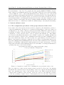
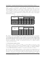
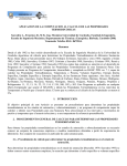
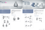
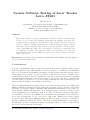
System Software Testing of Laser Tracker Leica AT401 Filip Dvořáček Department of Special Geodesy, Faculty of Civil Engineering Czech Technical University in Prague Thákurova 7, 166 29 Prague 6, Czech Republic [email protected] Abstract The article introduces a group of instruments called laser trackers and specifically focuses on one of them - Leica AT401. At the Research Institute of Geodesy, Topography and Cartography the instrument has been tested both in laboratory and outdoor conditions. Several significant errors in the instrument’s system software have been found, mostly due to the creation of user-programmed controlling application called ATControl. The errors are related to a selection, a computation and an evaluation procedure of the refractive index of air. Finally, notes of the new measurement modes of Leica AT40x are given and a range of distance measurement is discussed. Keywords: laser tracker, absolute distance measurement, Leica AT401, system software error, group refractive index of air 1. Introduction A group of instruments called absolute laser trackers has caused a small revolution in the field of length metrology. Although these devices are meant to be mainly used in industrial metrology (car and aircraft industry), the impact of laser trackers is far wider and also effects engineering geodesy. Relative precision as well as overall absolute accuracy of distance measurement has brought about new possibilities for surveyors and metrologists in determining the fundamental length unit. Laser trackers have become parts of laboratory equipment all over the world [1], as they are tools for creating standards and etalons and they provide metrological traceability to the definition of the meter. The Leica AT401 instrument was introduced to the public in 2010. Its successor AT402 with similar technical specifications and the same system software followed in 2013. The letters AT stand for Absolute Tracker, signifying that instruments implement a new technology called Absolute Distance Measurement. It is currently capable of superior accuracy stated by the manufacturer as a standard deviation of 5 µm over the whole 160 m working range [2]. Parameters of all up-to-date EDM (electronic distance measurement) devices, integrated in geodetic total stations, are not even close to this point. During past decades, ageing predecessor Kern Mekometer ME5000 with its accuracy 0.2 mm + 0.2 ppm × D km (D = measured distance) had held the status of the most powerful instrument for long distance measurement [3]. But recently, laser tracker systems have taken over this role and stand in the focus of current interest and research. Geoinformatics FCE CTU 13, 2014, doi:10.14311/gi.13.6 49 Dvořáček F.: System Software Testing of Laser Tracker Leica AT401 Research Institute of Geodesy, Topography and Cartography (RIGTC/VÚGTK) - Department of Metrology and Engineering Geodesy deals with both the laboratory and field testing of Leica AT401 in order to employ this instrument in the calibration process of the Czech State Long Distances Measuring Standard Koštice [4] and National Geodetic Baseline Hvězda. This article describes the system software errors found by the author and introduces some practical issues which occur during field measurement. Because of the lack of suitable geodetic software solutions on the market, the user-programmed Mathworks Matlab application called ATControl is used for communication with Leica AT401 during both testing and measuring. 2. System software errors 2.1. The computation procedure of the group refractive index of air If you want to know the way the refractive index is computed by the instrument, you have to contact the manufacturer. From Leica, a document describing this procedure was obtained on 5th May 2013 [5]. According to this paper and practical testing, AT401 uses equations derived from Edlén´s formula. A study was made in which 10 most popular procedures of indirect computation of group refractive index of air is compared and analyzed [6]. All formulae were derived from primary information sources. Edlén´s equation [7], originally published in 1966 and nowadays recognized by the community as inaccurate in terms of humidity, posted the worst result in the study. It reached nearly a 0.5 ppm difference from the Ciddor & Hill procedure (1996 [8], 1999 [9]) recommended by a resolution of the International Geodetic Association (IAG) in 1999 in Birmingham [10]. Leica’s modified formula showed no significant difference from Edlén’s. Although the testing parameters were quite extreme (up to 35 °C air temperature and 100% relative humidity) they are not unrealistic concerning the instrument´s operating range (up to 40 °C and 95%) [11]. Figure 1: Comparison of methods for evaluating the group refractive index of air There is a half-done solution in the system software prepared by Leica [12]. By changing Weather Monitor Status from Calculate (default) to Read only or Off, the user may implement their own computation procedure of the refractive index of air. This is exactly the way the complex Ciddor & Hill procedure and also others were added to the ATControl software to offer the possibility to make a choice. Unfortunately, there is doubt that ordinary users Geoinformatics FCE CTU 13, 2014 50 Dvořáček F.: System Software Testing of Laser Tracker Leica AT401 are able to apply this functionality because available commercial software solutions do not implement it. Therefore, only the default setting is usually available for measuring. 2.2. Wavelength of the ADM In the paper from Leica [5] you can find that AT401 operates on 795 nm wavelength. In the instrument’s manual 780 nm is declared [11]. A technical support reacted that the mistake is in the manual. To confirm this, a simple test including measuring with recording atmospheric parameters and refractive indices and theoretical calculations of given equations (1) and (2) was performed. Unfortunately, the measured and calculated results did not fit together, and therefore more research had to be done. 7.5 T 1 + 10−6 P (0.613 − 0.010 T ) . = AP − BR 10 T +237.3 +0.6609 1 + 0.0036610 T NGr_ppm . =1+ 1000000 " NGr_ppm NGr # (1) (2) Both 780 and 795 nm was now considered along with a variety of constants A and B (Table 1) given by Leica and calculated as stated in a presentation [13] of Munich University (3), (4). Constant B for 780 nm trackers which has been received from Leica is not in congruence with the equations, but this has a negligible impact on the results and will not be discussed here anymore. A = 86.8109 · 10−3 + λ B = 572.2 − 25.03792 0.16647 25.03792 0.166467 2 + 2 1 + 1 130 − λ2 38.9 − λ2 130 − λ12 38.9 − λ12 13.71 λ2 (3) (4) Table 1: Constants of the refractive model for Leica AT401 Constant A B×10−6 For trackers 780 nm Given by Leica Calculated 0.2917349 0.2917349 556.68 549.67 For trackers 795 nm Given by Leica Calculated 0.2914269 0.2914269 550.51 550.51 On the other hand, an incorrect substitution of 780 nm instead of 795 nm has much more serious consequences. The values of the refractive index calculated by Leica AT401 is in perfect match with the manually calculated refractive index if 780 nm wavelength and B constant given by Leica is employed. At this stage, the issue is very complex because all documents including Leica´s support answer are somehow wrong. The manual is wrong about 780 nm, the paper is wrong about the way AT401 computes the refractive index, and the technical support ensures about validity of the sent paper. In the end, the manufacturer recognized that Leica AT401 physically uses 795 nm wavelength, and the programmed default computation of the group refractive index of air is wrong. It can be estimated by error analyses that a mistake of 15 nm in the wavelength causes an error of the group refractive index by approximately 0.3 ppm. This analyses was confirmed also by practical calculations - see the 0.28 ppm difference in Table 2. Geoinformatics FCE CTU 13, 2014 51 Dvořáček F.: System Software Testing of Laser Tracker Leica AT401 Table 2: Analyses of the AT401 refractive model Atmospheric conditions Temperature Pressure Humidity [◦ C] [hPa] [%] 19.50 985.811 58.0 23.30 984.373 46.8 Calculated by AT401 1.0002679940 1.0002641449 Group refractive index of air Manually calculated 795 nm 780 mm, Bcalc 780 nm, BLeica 1.0002677165 1.0002680009 1.0002679940 1.0002638716 1.0002641519 1.0002641449 2.3. Improper updates of the group refractive index of air This error, improper updates of the refractive index of air in the memory of the instrument’s EmScon server, is considered by the author to be the most tricky and serious one. It was never acknowledged by the technical support as a real error, rather it was called the standard behaviour of the system. It is everyone´s choice which behaviour of the instrument is metrologically acceptable but it should be always transparent and predictable. When measuring with ATControl software, AT401 is always asked to return actual refractive indices used for calculated corrected measured distances. The indices are then saved beside other measured data for any post-processing purposes. The author soon noticed that the group refractive index remains unchanged even if atmospheric parameters differ in time. Only quite large jumps of the refractive index were registered from time to time. During a simple test, instrument’s external NTC temperature sensor was heated by hand to simulate significant changes of temperature (and refractive index). Table 3: Improper updates of the group refractive index of air Atmospheric conditions Temperature Pressure Humidity [◦ C] [hPa] [%] 22.6 984.354 48.3 22.8 984.361 48.0 22.9 984.383 47.7 23.0 984.335 47.5 23.3 984.373 46.8 23.7 984.314 45.8 22.8 984.170 49.0 23.0 984.200 48.4 23.3 984.165 47.6 Group refractive index of air Change ng [-] [ppm] Update 1.000264774151 1.000264774151 0.00 no 1.000264774151 0.00 no 1.000264774151 0.00 no 1.000264144921 -0.63 yes 1.000264144921 0.00 no 1.000264719968 0.58 yes 1.000264719968 0.00 no 1.000264079414 -0.64 yes From the results (Table 3) it was derived that the refractive index is updated only if a new value differs from an old one by 0.5 ppm or more. As investigated, this fulfils all measurements in automatic Calculate mode but also all measurement in manual modes Read Only and Off. In practice, if the refractive index is computed and handed over to the instrument, it is expected that the distance will be corrected by using this specific value. Nevertheless, in most cases, the instrument will use some old number stored in its memory and no information about it is provided. Such behaviour was confirmed by the technical support in Leica´s testing software called Geoinformatics FCE CTU 13, 2014 52 Dvořáček F.: System Software Testing of Laser Tracker Leica AT401 TPIAnalyzer. A print screen from this testing is available. Similar explicit testing could have been achieved in ATControl as well, but there was no need to do that anymore. The only functionality, which serves well and updates the refractive index immediately, is the command SetEnvironmentParams. In that case meteostation ATC400 is turned off, atmospheric parameters are inserted manually and the device will compute the refractive index automatically by the default Edlén´s procedure. However, these circumstances are not met very often during real measurement and this setting is inconvenient for practical use. By neglecting changes in the group refractive index of 0.5 ppm, simultaneously the changes in air temperature up to approximately 0.6 °C are not taken into account. This can be illustrated on the graph (Fig. 2). Temperature changes in time were simulated by spontaneous heating of the AT Controller 400 internal temperature sensor and the same length (31 m) was measured repeatedly. Obvious jumps of distance measurement were caused by the discussed firmware error which is demonstrated by the size of jumps - about 0.5 ppm. Figure 2: Improper updates of the refractive index of air by Leica AT401 Up to a 1 ppm difference between two measurements of the same distance can be found due to improper updates of the refractive index of air. The results depend on the fact if the refractive index (or temperature respectively) is rising or dropping and what is the previous value of the refractive index stored in the instrument’s memory. An answer from Leica´s technical support in Switzerland stated that all this had been programmed in order to speed up the whole system and eliminate delays. The author of the article assumes that it cannot be the real reason. Every time a new set of atmospheric parameters is observed (20 sec), the refractive index has to be computed anyway, but usually it is not saved as it should be. Promises of the customer support to pass this issue onto the developer department had been made, but one and a half years later no change in the instrument’s system software has taken place. In the ATControl application it was possible to overcome this error without any noticeable delay during the measurement process. In addition, it had to be arranged in a much more complicated way then Leica could do it. Correcting the error is possible only in manual Geoinformatics FCE CTU 13, 2014 53 Dvořáček F.: System Software Testing of Laser Tracker Leica AT401 modes Read only and Off of the meteostation. After obtaining atmospheric parameters (from ATC400 or elsewhere), wrong refractive indices (group and phase) are set. They have to differ from the correct ones at least 0.5 ppm. Afterwards, correct refractive indices are sent to the server and, because they differ so much, they are accepted as new values. And so when the measurement starts, the first velocity correction is ensured to be computed with the proper refractive index. Because of the facts stated above, it can be believed that ATConrol is one of a few or maybe the only software solution which deals with the error and provides metrologically correct distance measurement with Leica AT40x instruments. 2.4. Resolution of reading atmospheric parameters A temperature reading from the internal and external temperature sensor can be usually obtained only to a 0.1 °C resolution. For internal temperature sensor, which is heated up by electronics in the controller and gives up to 3 °C wrong results, it is understandable. For external NTC S2 sensor it is not the same case. In manual [11], Leica describes the accuracy as 0.3 °C expanded uncertainty. The same sensor, NTC S2, can be purchased from Hexagon Metrology, but surprisingly with only 0.2 °C expanded uncertainty. This makes only the 0.1 °C standard deviation of the absolute reading, and the relative repeated reading is most likely even smaller. For the external sensor, it seems reasonable to enable the reading of the temperature to be with the 0.01 °C resolution. Besides, jumps in measured distances caused by rough resolution of obtained digits are observed. To be faultless, it has to be said that temperature can be read to hundreds of °C when the absolute temperature drops below 10 °C (9,99 or lower). It seems only 3 valid digits are reserved in data type to store the value. An answer from Leica was that a change is not needed and that it is simply how their system works. It is partly true because by default they neglect everything smaller than 0.5 °C by not updating the refractive index. But in spite of this behaviour, atmospheric pressure is read to 0.001 hPa and relative humidity to 0.1 %. The expanded uncertainties of the installed atmospheric sensor and the humidity sensor are only 1.0 hPa and 5%. It proves that the programmed firmware does not reflect the way atmospheric parameters effect refractive indices (measured distances respectively). If the system was really designed to work with 0.5 °C error in temperature, also 1.5 hPa of atmospheric pressure and 30% of relative humidity errors would be acceptable. In the author´s opinion, better resolution to 0.01 °C for temperature could be beneficial for measurement. On the other hand, the resolutions concerning pressure and humidity could be lowered to 0.1 hPa and 1% without any noticeable change in measurement results. In user-programmed applications, this issue cannot be resolved without an interference to the system software (firmware) which is out of the user´s reach. 2.5. Summary of described firmware errors To demonstrate that the discovered errors are significant and should be taken into account by all current and potential users, a summary has been made. The purpose of the tables below (Table 4, Table 5) is to show how the errors may effect measuring with AT40x in ordinary conditions – laboratory and outdoor. The impacts of errors depend on ambient atmospheric conditions and its gradients as well as the length to the target point. Both extremes (Min, Max) of these error intervals are evaluated in the tables. The max. error is derived as the maximum possible influence for the whole instrument´s working range (<0; 160> m Geoinformatics FCE CTU 13, 2014 54 Dvořáček F.: System Software Testing of Laser Tracker Leica AT401 distance, <0; 40> °C temperature, <500; 1100> hPa atmospheric pressure, <0; 95> % relative humidity). In laboratory conditions, stability of temperature ±0.25 °C at 20 °C and 30 m length are assumed. A reduced range of temperature <0; 30> °C is used for the outdoor evaluation. Notice that an error in the group refractive index of air causes an error of about the same amount in the measured distance (km). Each of the described issues itself potentially exceeds the manufacturer´s specification about the accuracy of the distance measurement (5 µm) [2]. Table 4: Impacts of AT40x firmware errors [ppm] Error Refractive model Wavelength Updating n All together Max. error Min 0.01 -0.31 -0.50 -0.80 Max 0.64 -0.27 0.50 0.87 Estimated common error Laboratory Outdoor Min Max Min Max 0.07 0.12 0.01 0.32 -0.28 -0.28 -0.28 -0.27 -0.25 0.25 -0.50 0.50 -0.46 0.09 -0.77 0.55 Table 5: Impacts of AT40x firmware errors [µm] Error Refractive model Wavelength Updating n All together Max. error (160 Min 2 -50 -80 -128 m) Max 102 -43 80 139 Estimated common error Laboratory Outdoor (30 m) (160 m) Min Max Min Max 2 4 2 51 -8 -8 -45 -43 -8 8 -80 80 -14 3 -123 88 The question occurs of how it is possible that no one has noticed or corrected the issues. Some answers can be found. Firstly, errors of refractive model and faulty wavelength have opposite mathematic signs and therefore partly eliminate each other in results. Finally, testing and measuring with laser trackers is mostly done in world-class laboratories equipped with effective air conditioning. A well-controlled environment with a stable temperature during the whole measurement process fully or at least largely reduces the error of improper updates of the group refractive index. 3. Measurement modes system Laser trackers are still a relatively new family of products which are undergoing a rapid development and innovations. Under these circumstances, minor errors in functionality will not be criticized and discussed here. A frequency of about a half year of issuing new firmware to Leica AT40x instruments is sometimes too long if an error is desired to be fixed. Since the time of a major firmware upgrade to version 2.0.0.5053, new measurement modes have been introduced and all applications should have implemented them. The precise, standard, fast or outdoor mode can be chosen. Only a brief general description of profiles is given by Leica, no specifications are available. Users may only guess that the difference consists of Geoinformatics FCE CTU 13, 2014 55 Dvořáček F.: System Software Testing of Laser Tracker Leica AT401 measurement time (0.5 - 5 s) and also a tolerance to changing environmental conditions. According to the author´s experience, the precise mode was useable in the laboratory only up to 30 m, even though the description said it was meant to be used in uncontrolled environment. The outdoor mode, dedicated to use in “harsh environment” in field conditions, was practically not useable outdoors at all because it was not capable of determining longer distances. On the other hand, the standard mode, which should be used in a controlled environment, worked the best outside the laboratory. Leica´s support answer was that if the users were fine with the standard mode in field conditions, they should have used it. The main idea of the outdoor mode is: “To make it less sensitive to disturbing light sources like reflections of the sunlight.” So with firmware 2.0.0.5053, 2.0.1.5449 and 2.1.0.4864 the standard mode was used, but since upgrading to the recent version 2.2.0.5975, a decrease of the distance range was observed. The standard mode stopped working for longer distances. The outdoor mode has operated up to about 120 m but it is far less than it was able to measure before – about 180 m. From our reseller NMS Slovakia (noncontact measuring systems), information was given that this firmware version dealt with unwanted reflections and so it might have affected also the sensitivity to the measuring signal. Users do not have an option to make a downgrade in the Tracker Pilot application and, therefore, Hexagon Metrology service centre in Prague had to be asked to do it. Unfortunately, even after downgrading to version 2.1, similar problems with long distances above 100 m are present. It is believed that extended calibration of the instrument, which makes all laser beams perfectly coaxial, will return back the required capability of measuring long distances. Measuring long distances in field conditions with the AT401 is always challenging. The changeable atmosphere and the current hardware state make it difficult enough. Additional uncertainties in the measurement mode system make it even more complicated to recognize what is the problem during measurement. The description of the error no. 113316 “Distance measurement failed. General error upon a distance acquisition.” is not much helpful. Reaiming to the target in order to receive a stronger reflected signal increases the chance for a successful measurement. Author’s note The purpose of the article is far from an assumption that the author wanted to cause any harm to Leica Geosystems, Hexagon Metrology, NMS Slovakia or somehow discredit the qualities of the instrument itself. RIGTC/VÚGTK has been regularly using Leica AT401 for several years and may recommend this instrument to other users. On the other hand, if technical support does not reflect desired changes in the system software, spreading serviceable information among end users is what needs be done. The majority of customers are satisfied with the functionality of the instrument as it came from production. However, if someone wants to fully take advantage of the potential of such a great hardware, significant attention should be dedicated not only to the hardware, but to the firmware and software as well. The presented results of the paper are not dependent on the used testing software and can be verified by any user-programmed controlling application which enables saving of group refractive indices. Contact the author of the paper in order to get the ATControl software for free for further non-commercial scientific use. Geoinformatics FCE CTU 13, 2014 56 Dvořáček F.: System Software Testing of Laser Tracker Leica AT401 References [1] GASNER, G. a R. RULAND. Instrument Tests with the New Leica AT401 [online]. Stanfort, CA, USA: SLAC, 2011 [cit. 3.5.2014]. Available: http://www.slac.stanford.edu/ cgi-wrap/getdoc/slac-pub-14300.pdf [2] Leica Geosystems. Leica Absolute Tracker AT401: ASME B89.4.19-2006 Specifications. Leica Geosystems, 2010-12-14, 2010. [3] JOKELA, Jorma a Pasi HÄKLI. On Tracebility of Long Distances . Lisbon, Portugal: International Measurement Confederation, 2009 [cit. 28.5.2014]. Available: http://www. imeko2009.it.pt/Papers/FP_100.pdf [4] LECHNER, Jiří et al. Nový český státní etalon velkých délek Koštice. VÚGTK, 2007 [cit. 29.5.2014]. Available: http://www.vugtk.cz/odis/sborniky/jine/geos07/ paper/32_lecher_cervinka_umnov_kratochvil/paper/32_lecher_cervinka_umnov_ kratochvil.pdf [5] Leica Geosystems. Formula for Calculating the Refractive Index of Ambient Air used for the Leica AT401 of Hexagon Metrology. , 2013-02-13, 2013. [6] DVOŘÁČEK, Filip. Nepřímé určení indexu lomu vzduchu pro výpočet fyzikální redukce elektronických dálkoměrů. Geodetický a Kartografický Obzor. 2013, vol. 101, no. 10, s. 253-266. ISSN 1805-7446. [7] EDLÉN, B. The refractive index of air [online]. Metrologia. 1966, vol. 2, no. 2, s. 71-80 [cit. 28 November 2012] Available: http://www.scopus.com/inward/record.url?eid= 2-s2.0-34250009147&partnerID=40&md5=769ccc0fb3a3cd511ba00a8b8cfb7e38 [8] CIDDOR, P. E. Refractive index of air: New equations for the visible and near infrared [online]. Applied Optics. 1996, vol. 35, no. 9, s. 1566-1572 [cit. 28.11.2012] Available: http://www.scopus.com/inward/record.url?eid=2-s2. 0-0030404182&partnerID=40&md5=cc21b031fafd06b6e8cd384decd7a103 [9] CIDDOR, P. E. a R. J. HILL. Refractive index of air. 2. Group index [online]. Applied Optics. 1999, vol. 38, no. 2-9, s. 1663-1667 [cit. 28.11.2012] Available: http://www.scopus.com/inward/record.url?eid=2-s2.0-0000063725&partnerID= 40&md5=cb84d76662da432a853142d88c93bd9f [10] RUEGER, J. M. Refractive Indices of Light, Infrared and Radio Waves in the Atmosphere. University of New South Wales, 2001. ISBN 9780733418655. [11] Leica Geosystems. Leica AT401 User Manual V. 2.0. , 2013. [12] Leica Geosystems. emScon 3.8: Leica Geosystems Laser Tracker Programming Interface - Programmers Manual. Revision 3 ed. Switzerland: , 2013-07-27, 2013. [13] HENNES, Maria et al. State of the art baseline measurements by means of laser tracking – results from an interlaboratory comparison. Praha EURAMET, 2011. Geoinformatics FCE CTU 13, 2014 57