1
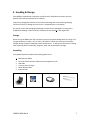
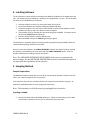
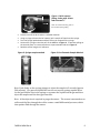
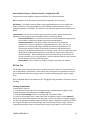
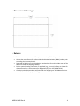
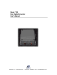
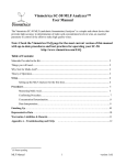
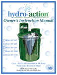
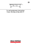
Mobile Density Meter: MDM100 Liquid Density Meter Installation and Operation Manual Part No.: FM0514 MDM Rev A Last Updated: 2014 Contents 1. Introduction ................................................................................................................................................4 Applications ................................................................................................................................................4 Technology Overview .............................................................................................................................5 Technical Specifications .........................................................................................................................5 2. General Safety.............................................................................................................................................6 Safety Conventions: Please note the following safety conventions: ....................................6 Operational Safety Considerations ....................................................................................................6 3. Handling & Storage ..................................................................................................................................7 Storage...........................................................................................................................................................7 Unpacking ....................................................................................................................................................7 4. Installing Software ...................................................................................................................................8 5. Sampling Method ......................................................................................................................................8 Sample Preparations ...............................................................................................................................8 Injecting a sample .....................................................................................................................................8 Figure 1: Quick connect fitting, shown with 14 mm tube inserted ¾” .....................................9 Figure 2: Syringe sample method.............................................................................................................9 Figure 3: Port Extender Sample Method ...............................................................................................9 6. Operating the Software ....................................................................................................................... 10 Simple Interface Mode ......................................................................................................................... 10 Figure 4: Simple Interface Mode Screen Shown.............................................................................. 10 Advanced Interface Mode ................................................................................................................... 10 Parameter Tab......................................................................................................................................... 11 Menu: Measuring Variables > System Units > Configuration042 > Unit density............... 11 Menu: Measuring Variables > System Units > Configuration042 > Unit ref density........ 11 Menu: Measuring Variables > System Units > Configuration042 > Unit temperature .... 11 Menu: Output ................................................................................................................................................. 11 Menu: Basic Function ................................................................................................................................. 11 Menu: Special Function > Density Function > Configuration 700 ........................................... 12 RT Data Tab .............................................................................................................................................. 12 Viewing Graphed Data ............................................................................................................................... 12 Adjust Tab ................................................................................................................................................. 13 FM0514 MDM Rev A 2 Calibrating Density Single Point ............................................................................................................ 13 Calibrating Density Using Water ........................................................................................................... 13 Viscosity calibration.................................................................................................................................... 14 7. Cleaning the Sensor............................................................................................................................... 15 Air Cleaning the Sensor ....................................................................................................................... 15 Solvent Cleaning the Sensor .............................................................................................................. 15 Cleaning the Sensor with Pure Water............................................................................................ 15 8. Dimensional Drawings......................................................................................................................... 16 9. Returns ....................................................................................................................................................... 16 Addendum 1: Definitions.................................................................................................................................... 17 Legal Disclaimer ..................................................................................................................................................... 18 FM0514 MDM Rev A 3 1. Introduction The Mobile Density Meter (MDM) is the ideal solution for laboratory, in-plant and field measurements of liquid density. Viscosity measurement (kinematic and dynamic) can also be included, if purchased as an option. The density sensor operates at ambient temperature, resulting in very fast analysis. An on-chip temperature sensor is included. Temperature along with measured density is used to calculate fluid properties such as specific gravity, API gravity, Brix, Plato and ethanol alcohol concentration in distillation operations. A windows computer (desktop, laptop or tablet), running Fluidic Communication Software, communicates with the MDM with the USB cable. Power to operate the MDM comes through the USB interface. The MDM is packaged in a lightweight, rugged plastic case that is also weatherproof. It is designed to operate in general purpose electrical environments. Samples are injected into the MDM using standard syringes. Liquid waste is collected in a usersupplied container. A very small amount liquid (<10ml) is required for a measurement. Applications The MDM is the ideal solution for lab, in-plant and field measurements of liquid density. The MDM can be used in a wide variety of industries with these example applications: Fuel and Energy Food and Beverage Environmental Clean in Place (CIP) FM0514 MDM Rev A Density of gasoline, diesel and jet fuel Viscosity of gasoline, diesel and jet fuel Fuel quality determination Methanol concentration in water Brix in winemaking SG and Plato of beer worte Brix of fruit juice and cider Liquors and spirits Salt concentration of water Dissolved solids in water Pesticides Liquid fertilizer Check the concentration of caustic and nitric acid in CIP systems 4 Technology Overview MDM 100 instrument measures fluid density based on the principle of an oscillating micro tube. The micro sensor oscillates at a very high frequency (>20kHz) and is not affected by environmental vibrations, which make it ideal for portable applications. Integrated on the sensor is a close-coupled platinum RTD temperature sensor to the sensing tube. This assures the measured liquid temperature and fluid density are closely aligned. The vibrating micro tube sensor can also measure liquid dynamic viscosity. Combining the dynamic viscosity and measured density results in the ability of the MDM to report viscosity as a kinematic value in centistoke units. The small size of the sensor results in a naturally bubble resistant design which is advantageous in measuring gas saturated fluids such as wine, beer, hard apple cider and soft drinks. Technical Specifications GENERAL Density Range Accuracy Max Pressure Operating Temperature Sample Update Rate Materials Dimensions Weight POWER Supply Current ELECTRICAL Data Communication OTHER OPTIONS 0.6 - 1.3 g/cc Digital Density: 0.0005 g/cc Temperature: +/- 0.6 F (0.3 C) 15 psig 41 32 to 158 F (5 0 to 70 C) (do not allow water to freeze in the sensor) 100 mS Exterior Case: high impact polycarbonate plastic Sensor: Stainless Steel, Silicon, Epoxy, Glass 9.44" x 7.8" x 4.29" (24 x 19.8 x 10.9 cm) 3 lbs. (1.3 Kg) PC USB port, 5 VDC 35 mA USB A Dynamic and Kinematic Viscosity (0 to 50 cP, 0 to 50 cSt) FM0514 MDM Rev A 5 2. General Safety Safety Conventions: Please note the following safety conventions: WARNING! Indicates an action or procedure which, if not performed correctly, can result in injury or a safety hazard. Comply strictly with the instructions and proceed with care. Caution: Indicates an action or procedure which, if not performed correctly, can result in and incorrect operation or destruction of the device. Comply strictly with the instructions. Note: Indicates an action or procedure which, if not performed correctly, can have an indirect effect on operation or trigger an unexpected response on the part of the device. Operational Safety Considerations The MDM is not designed for operation in hazardous environments. Strict compliance with these installation and operation instructions is a requirement. The manufacturer reserves the right to modify technical specifications and installation instructions without prior notice. Please contact your local agent to confirm that you have the latest version of the MDM User Manual. Assistance in clarifying the chemical resistance properties of the wetted materials exposed to process fluids, including fluids used for cleaning the sensor, is available from ISSYS. Changes in fluid temperature, chemical concentration or the degree of contamination in the process fluid can result in changes in the wetted material chemical resistance properties. Liability for wetted material chemical compatibility in a specific application is the responsibility of the user. The user is responsible for determining if the fluid wetted materials are compatible with the process fluid. Caution: The MDM has no repairable components. Do not attempt to open the case. Caution: Freezing and solute crystallization can permanently damage the instrument. In certain applications, pre-filtration to at least 60 microns of the injected fluid is recommended to prevent clogging the sensor. FM0514 MDM Rev A 6 3. Handling & Storage Every MDM is shipped with a calibration certificate and a CD-ROM that contains the User Manual and Fluidic Communication PC software. Inspect the package and contents to ensure that no damage has occurred during shipping. Contact the factory if damage has occurred or is suspected prior to installation. On receipt, inspect the packaging and package contents for any damaged or missing items. If additional shipping is required, always transport the instruments in the original box. Storage When storing the MDM, pack the instrument to protect it against damage while in storage. The storage temperature range is -4°F to 176°F (-20 to 80°C). Protect the instrument from direct sunlight during storage to avoid high surface temperatures. To protect the device from freezing after measuring water compounds, purge the meter with alcohol before storage. Unpacking Every MDM shipment includes these following basic items: MDM Mobil Density Meter PC Fluidic Communication Software and user guide on a CD USB cable 2 starter plastic syringes Waste disposal tube Injection tube CD – Software & Manual FM0514 MDM Rev A USB Cable Waste & Injection Tube 7 4. Installing Software The PC software is used to display and configure the MDM is included on a CD supplied with the unit. The software must be loaded on a computer running Windows 7 or later. The CD includes the driver to run the MDM via the USB port. 1. Load the software on the PC by running the setup file on the CD. 2. Connect the MDM to the computer using the supplied USB cable. 3. Locate the program in the start menu called, Fluidic Communication Software and the software will start up and a user display screen will appear. 4. The software will try to find the port communicating with the MDM. If the port cannot be found the STATUS light will glow red. 5. Click the refresh button to select a different port. 6. When the MDM is found, the STATUS light will glow green. The installation is complete and you can begin measuring samples using the MDM. Follow the recommended sampling method in this manual. Be sure to have the software in the SIMPLE INTERFACE mode for the display mode by opening the software, click DISPLAY on the top menu and click SIMPLE INTERFACE option. Then the window will display the readings from the instrument. Note: The ADVANCED INTERFACE WITH CONFIG allows users to customize the meter settings. See the SOFTWARE DESCRIPTION section for detailed description of the operation and capabilities of the software. 5. Sampling Method Sample Preparations The MDM will measure liquids that are clean (free from particles) and with viscosities less than 50 cP, over a density range of 0.6 to 1.3 grams/cc. If the sample is dirty the user must filter the fluid to at least 60 microns before injection. An alternative method would be to use a syringe filter (20 micron). Note: The warranty is void if the sensor gets plugged due to particles. Injecting a sample Connect the drain tube to the MDM outlet port. A quick connect fitting is used. Make sure the tube is pushed in at least 3/4” or 19mm to prevent any leaks. FM0514 MDM Rev A 8 Figure 1: Quick connect fitting, shown with 14 mm tube inserted ¾” Note: To remove the tubing, push on the end while pulling tubing Place the end of the drain tube in a suitable container Using a syringe (at least 10ml of capacity) pull a sample of liquid into the syringe. Turn the syringe upside down and push out any air trapped in the syringe Connect the syringe to the inlet port of the MDM as in Figure 2. To prevent spilling on the internal plate, it is recommend to use a port extender tube as in Figure 3. Read the results using the PC software Figure 2: Syringe sample method Figure 3: Port Extender Sample Method Note: Push firmly on the syringe plunger to inject the sample in 3 seconds (approx. 200 ml/min). For gaseous liquids like beer do not turn the syringe upside down. Let the gas bubbles rise in the syringe to separate the liquid from the gas and then inject the sample until the beer/gas interface. Note: A firm injection is required to purge the sensor. The sensor is mounted on an orifice and the flow through the orifice creates a small differential pressure, which then pushes fluid through the sensor. FM0514 MDM Rev A 9 6. Operating the Software When the software is opened the either the SIMPLE or ADVANCED INTERFACE viewing mode will appear. When restarting the software, the last display mode used will appear. The display can be toggled between the modes using the DISPLAY dropdown menu To view a simple interface, select Display > Simple Interface. To view the tabs and options, select Display > Advanced Interface with Config. Simple Interface Mode The simple interface is the viewing mode that provides a display for viewing measurements and is the recommended viewing mode when taking samples. It shows the measured density in the selected units, temperature in the selected units, viscosity if purchased as an option and any concentration calculation selected. See FIGURE 1 for an example. Figure 4: Simple Interface Mode Screen Shown Advanced Interface Mode The advanced Interface is used to customize and configure the settings, naming conventions, measuring coefficients and more of the MDM. It consists of 4 main tabs: Param - Used for configuring and customizing the instrument’s settings in real time RT Data - Allows the user to plot the data on the PC screen and to store data on the PC hard drive Internal Data - Not available with the MDM because there is no internal memory Adjust - Used to calibrate density and viscosity measurements in the MDM FM0514 MDM Rev A 10 Parameter Tab Under the parameter tab, the user can customize and configure the settings for the MDM. The Param tab contains two main areas: Parameter Selection Tree—Lists all of the instrument’s parameters in an expandable tree menu. Parameter Settings View—Main area of the interface that displays the selected parameters from the tree menu and allows you to change the settings in the connected instrument. Menu: Measuring Variables > System Units > Configuration042 > Unit density This menu allows the user to select the units of density and temperature for the measurement. Options in this dropdown define measurement units: g/cm3 g/cc kg/L kg/m3 Lb/ft3 Lb/gal YYYY—Special density units that are user-defined. SG—Specific gravity. See Addendum 1, Definitions for more information. Menu: Measuring Variables > System Units > Configuration042 > Unit ref density Units of reference density option is the units for correcting the density back to temperature reference condition. Options in this dropdown change the units of reference density: g/cm3 g/cc kg/L kg/m3 Lb/ft3 Lb/gal API—American Petroleum Institute. See Addendum 1, Definitions for more information. Menu: Measuring Variables > System Units > Configuration042 > Unit temperature Controls in this dropdown define the temperature units: C—Celsius K—Kelvin F—Fahrenheit R—Rankine Menu: Output The Output Function does not apply for the MDM. Menu: Basic Function The Basic Function does not apply for the MDM. FM0514 MDM Rev A 11 Menu: Special Function > Density Function > Configuration 700 Programs the thermal expansion equation coefficients for fixed concentration. Off—No additional concentration formulas will be computed in the instrument. Ref Density—The reference density boxes must be populated with the correct coefficients. Reference density is the measured density recalculated at a fixed temperature using an expansion equation in the MDM. The factors for the expansion equation are entered into the MDM. Concentration—The user can customize the concentration names. Up to 4 concentration equations can be programmed into the MDM. Define the following values: Concentration Selector—List of the concentration conversion equations programmed into the device. Select one to enable converting measured density. Concentration Names—This options defines the name of the concentration measurement. Up to four equations can be programmed at a time. The user can generate a new name by selecting an unfilled box and entering coefficients. The concentration equation requires constants that use density and temperature to calculate for example the concentration of alcohol in water. These constants have to be calculated by Integrated Sensing Systems using tables of concentration, density and temperature data. When entering constants care must be taken to insure they are correct to prevent errors in the calculation. Note the exponent value for each constant. Consult the factory for the coefficient factors. Density Mode—This is a label only. % Mass, % Volume, and Other are available. RT Data Tab The RT Data Tab provides a graph view of any parameter data in real time. This tab allows the user to plot density, temperature. Concentration and viscosity data at a selected time interval. This is useful when manually injecting a series of samples and displaying the results in graph form. Note: Graphed data is not saved to a file. The graph only provides a real-time view of the data. Viewing Graphed Data To view data in real time: 1. In the Value to Plot list, select up to three parameters to be plotted on the graph. Select multiple parameters by holding down the Shift or Ctrl key. 2. Select the Start Graphing button to view the graph in the main window. 3. Initially, the plotting will start in Auto Scale mode. To adjust the scale, click the Autoscale button on the lower left-hand side of the data graph. The user can adjust the range by toggling the switch at the bottom between range and position. Range is adjusted by using the mouse on the range to pull down to increase the range and push up to decrease the range. Position is selected by putting the mouse on the scale and moving it up and down. The Y-axis scale or FM0514 MDM Rev A 12 position can be changed by clicking and dragging the cursor over the Y-axis. To clear the chart and begin again, click Stop Graphing and Clear Graph to erase the graphed data. Data can be recorded at the rate selected for graphing. Press the START REALTIME recording and a window will appear asking for the file name for the data. STOP REALTIME recording. To adjust the rate of data acquisition in seconds use the adjustment arrow at the bottom of the page. The rate can be manually entered as an option. The recorded data can be found in the program files under RT Data in the program files. Adjust Tab The Adjust Tab is used by the use to calibrate the density and viscosity measurements. The density calibration or flow indicator offset may need to be adjusted at startup or during the life of the meter. These adjustments are made in the Adjust tab. All instruments are calibrated under reference operating conditions at the factory. It is generally not necessary to perform a density adjustment. The density accuracy may drift with time due to normal wear or coating the flow channel. It is recommended to clean the instrument if drift is noticed. Caution: Care must be taken when making any changes. This adjustment can affect the accuracy of measurements. To verify measurement, and to correct if necessary: 1. Clean the flow channel with an appropriate solvent, flushing in both directions, if possible. Completely dry the channel with pressurized clean air or nitrogen for best results. 2. Go to the Adjust tab and enter the access code: 0020. 3. Click OK. Calibrating Density Single Point A single point calibration can be done if the density of a known fluid is known. The instrument can be calibrated for specific density if the density is a known parameter. This requires that the sensing tube is full of the material being measured. The temperature reading should also match the temperature of the sample or flow material. If all these conditions are met, you can set the density point. 1. In the Adjust tab, click the Calibrate Density Single Point button. 2. Enter the density value and click OK. Calibrating Density Using Water A built-in water calibration can be accomplished. Follow the cleaning instructions then calibrate density using water after the cleaning. Fill the flow channel with the degassed, demineralized water, read the density, and compare this value to published values. If the density accuracy is out of specification, perform a density adjustment. This instrument has a one-point density adjustment function available using pure water. Note: This function overwrites the field density calibration. FM0514 MDM Rev A 13 1. Ensure the instrument is at a stable temperature and not exposed to direct sunlight or other heat sources during this adjustment. 2. Inject or flow de-ionized or distilled water. 3. In the Adjust tab, select Calibrate Density Using Water button. A new calibration is completed and stored. Viscosity calibration Viscosity calibration requires the precise viscosity of a known fluid. For example the viscosity of water at specific temperature. FM0514 MDM Rev A 14 7. Cleaning the Sensor Air Cleaning the Sensor To clean the sensor between measurements, use a second syringe filled with air and quickly inject into the meter. This will push previous sample to the waste disposal container. It will also minimize cross contamination between samples. Solvent Cleaning the Sensor When finished sampling and storing the MDM it is recommended that the sensor be cleaned with an appropriate solvent. For hydrocarbons, a solvent such as isopropyl alcohol or hexane be used. This should remove any trace of chemicals in the sensor. To clean the sensor of any liquid, use a second syringe filled with air and inject into the meter using the inlet port. This will push any cleaning solvent to a waste disposal container. Cleaning the Sensor with Pure Water The sensor can be rinsed with pure water (distilled) which is ideal when water based chemicals have been in the sensor. To clean the sensor between measurements, use a second syringe filled with pure water and inject into the meter. This will push previous sample to the waste disposal container and will also minimize cross contamination between samples. For water based solutions, use distilled water to flush the sensor. Look at the display on the PC and when display reaches the density of pure water at the temperature (or a specific gravity of 1) then the sensor is flushed. NOTE: In freezing temperatures, do not leave water in the sensor. The water can freeze, breaking the sensor. Always rinse with an alcohol such as ethanol or isopropyl alcohol before storing the sensor in cold weather. Freezing in the sensor will void the warranty. FM0514 MDM Rev A 15 8. Dimensional Drawings 9. Returns If the MDM instrument needs returned for repair or calibration, follow this procedure: Contact the manufacturer for a Return Merchandise Authorization (RMA) number prior to sending the instrument back. Download an RMA form from the website, complete the form and include a copy of the RMA form inside the shipping container. Enclose special handling instructions, if applicable (e.g., a material safety data sheet for chemicals used in the instrument as per Regulation (EC) No. 1907/2006 REACH). Clearly print the RMA number on the outside of the shipping box. All RMA instructions must be adhered to for proper handling. FM0514 MDM Rev A 16 Addendum 1: Definitions API – American Petroleum Institute API gravity is a measure of how heavy or light a petroleum liquid is compared to water. If its API gravity is greater than 10, it is lighter and floats on water; if it is less than 10, it is heavier and sinks. API gravity is thus an inverse measure of the relative density of a petroleum liquid and the density of water, but it is used to compare the relative densities of petroleum liquids. API = (141.37265/ ReferenceDensity) - 131.5. Reference density is corrected back to whatever reference temperature the user selects and also must enter the expansion coefficient of the fuel type. The formula to obtain API gravity of petroleum liquids, from relative density (RD), is: API gravity = 141.5/RD - 131.5. Conversely, the relative density of petroleum liquids can be derived from the API gravity value as RD at 60 F = 141.5/(API gravity + 131.15). A heavy oil with a relative density of 1.0 (at 60°F) would have an API of 141.5/1.0 = 131.5 = 10.0 degree API. When converting between density and relative density, it is important to use the correct density of water, according to the standard conditions used when the measurement was made. The official density of water at 60°F according to the 2008 edition of ASTM D1250 is 999.016 kg/m3. The 1980 value is 999.012 kg/m3. In some cases the standard conditions may be 15°C (59°F) and not 60°F (15.56°C), in which case a different value for the water density would be appropriate. Specific Gravity - Specific gravity for liquid is defined as the measured liquid density of the fluid at the measured temperature, divided by the density of pure water at the same temperature. SGliq = density(liquid)/density of water at same temperature. Dry Air density = PressureIn*6.895/287.07*(Temp MEMS+273.15). Example: Density of air at 25 C and 15 psi absolute = 0.0012083 grams/cc. FM0514 MDM Rev A 17 Legal Disclaimer ISSYS assumes no responsibility for infringement of patents or rights of others based on ISSYS applications, assistance or product specification since ISSYS does not possess full access concerning the use or applications of customers' products. ISSYS also assumes no responsibility for customer' product designs and the impact of the design on the device or other components in the products or samples being tested or monitored by the product and interactions between these items. The information in this document is believed to be accurate in all respects at the time of publication but is subject to change without notice. Integrated Sensing Systems assumes no responsibility for errors and omissions, and disclaims responsibility for any consequences resulting from the use of information included herein. Additionally, Integrated Sensing Systems assumes no responsibility for the functioning of undescribed features or parameters. Integrated Sensing Systems reserved the right to make changes without further notice. Integrated Sensing Systems makes no warranty, representation or guarantee regarding the suitability of its products for any particular purpose, nor does Integrated Sensing Systems assumes any liability arising out of the application or use of any product or circuit, and specifically disclaims any and all liability, including without limitation consequential or incidental damages. This product is not designed, intended, or authorized for use in applications intended to support or sustain life, or for any other application in which the failure of the Integrated Sensing Systems product could create a situation where personal injury or death may occur. Should Buyer purchase or use Integrated Sensing Systems products for any such unintended or unauthorized application, Buyer shall indemnify and hold Integrated Sensing Systems harmless against all claims and damages. Other products or brand names mentioned herein are trademarks or registered trademarks of their respective holder. FM0514 MDM Rev A 18 391 Airport Industrial Drive Ypsilanti, Michigan, USA 48198 Phone: 734-547-9896 FAX : 734-547-9964 Email: [email protected] www.metersolution.com FM0514 MDM Rev A 19