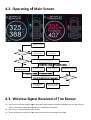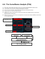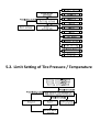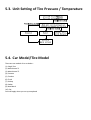
1
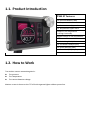
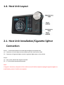
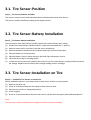
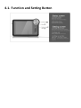
2015
TPMS GT-User manual
Content
1.1.
1.2.
Product Introduction.............................................................................................................................. 2
How to Work .......................................................................................................................................... 2
1.3.
1.4.
2.1.
3.1.
Package Content..................................................................................................................................... 3
Host Unit Layout .................................................................................................................................... 4
Host Unit Installation/Cigarette lighter Connection .............................................................................. 4
Tire Sensor-Position ............................................................................................................................... 5
3.2.
3.3.
3.4.
4.1.
Tire Sensor-Battery Installation ............................................................................................................. 5
Tire Sensor-Installation on Tire .............................................................................................................. 5
Frequently Asked Questions (FAQ) ........................................................................................................ 6
Function and Setting Button .................................................................................................................. 7
4.2.
4.3.
4.4.
5.1.
Operating of Main Screen ...................................................................................................................... 8
Wireless Signal Received of Tire Sensor................................................................................................. 8
Tire Surveillance Analysis(TSA) .............................................................................................................. 9
Function and Setting ............................................................................................................................ 10
5.2.
5.3.
5.4.
Limit Setting of Tire Pressure / Temperature ....................................................................................... 11
Unit Setting of Tire Pressure / Temperature ........................................................................................ 12
Car Model/Tire Model ......................................................................................................................... 12
5.5.
5.6.
5.7.
7.1.
Sensor Alignment ................................................................................................................................. 14
Time Setting ......................................................................................................................................... 15
Default Setting ..................................................................................................................................... 16
Specifications ....................................................................................................................................... 17
8.1.
Notice ................................................................................................................................................... 17
1.1. Product Introduction
TPMS GT Features
Tire Pressure Monitor(TPM)
Tire Temperature Monitor
Tire Pressure Lower/Upper Alarm
Tire Temperature Upper Alarm
Prompt of Tire Temperature
is Rising Continually
Suggest Prompt of Tire Temperature
Tire Pressure Abnormal Alarm
Tire Air Leaking Slowly Alarm
Tire Surveillance Analysis(TSA)
Tire Sensor Monitor(TSM)
Real Time Clock(RTC) Display
1.2. How to Work
Tire wireless sensors transmitting data’s:
Tire pressure
Tire Temperature
Tire sensors batteries voltage
Monitor screen is shown on the TFT LCD with cigarette lighter cable as power line
1.3. Package Content
(Host package)
Description
Q’ty(Pcs)
Host unit(TFT LCD)
1
Cigarette lighter Cable
1
Tire sensor
10
Tire sensor battery (CR1632)
10
Anti-thief nut
10
(Tire sensor spanner)
1
Mounting bracket
1
Antenna
1
Antenna mounting bracket
1
Antenna extension cable (including convertor)
1
User manual
1
(Accessories package)
Description
Q’ty(Pcs)
Tire sensor
12
Tire sensor battery (CR1632)
12
Anti-thief nut
12
(Tire sensor spanner)
1
(Position sticker)
1
User manual
1
1.4. Host Unit Layout
2.1. Host Unit Installation/Cigarette lighter
Connection
Step 1:Connection between host and cigarette lighter with power line
(1) Connector of circle shape connects power port (DC-Jack) on host side.
(2) Connector of cigarette lighter connects cigarette lighter port on the vehicle.
Step 2:
(1) Turn on the vehicle that engine is booted.
(2) TFT LCD will be booted automatically.
Note:
If engine is shut down, the power of host will not turn off will be required unplug the cigarette lighter to
avoid battery power of vehicle consumption.
3.1. Tire Sensor-Position
Step 1:Tire sensors position and label
The sensors positions come with individual label to indicate the position from the tire.
The sensors shall be installed according to the design position.
3.2. Tire Sensor-Battery Installation
Step 2:Tire Sensor Battery Installation
The tire sensors come with Lithium CR1632 original Swiss made military spec. battery.
(1) Prepare the sensor battery CR1632 Lithium, locate and understand the +/- polarity.
(2) Remove sensor cap by unscrew it from the sensor metal body.
(3)
(4)
(5)
(6)
Remove the battery metal cover by unclip the both clips (short and long clips).
Place the battery in correct polarity.
Place the battery cover in place and press the both clips with proper closure.
Close the sensor cap by screwing tightly.
(7) In order the tire sensor work properly, the screen of host tire sensor battery reading shall be minimum
2.8 Voltage. Replace sensor battery when voltage reading under 2.8 Voltage.
3.3. Tire Sensor-Installation on Tire
Step 3: Installation Tire Sensor on vehicle tire
Before installation please is sure the position of each sensor shall be correctly placed.
(1) Remove tire-valve cap
(2) Screw-in of clockwise direction the safety lock not into tire-valve.
(3) Place the tire sensor on designated position.
(4) Screw it tightly.
(5) Screw-in of counterclockwise direction that sensor and anti-thief nut tightly with dedicated spanner.
Note:
The tire sensor shall be fitted and screw tightly to avoid tire pressure leakage.
3.4. Frequently Asked Questions (FAQ)
(1) FAQ 1:After Host turned on for 5 minutes, it still shows failure of receiving wireless signal
Solution:
1.
Please make sure if the batteries are in reverse.
2.
3.
(Negative is poured at bottom side and positive at upper side)
Please make sure the snap of battery is in close of the batteries.
Please make sure if voltages in the batteries are enough; please replace with new ones if less
than 2.8 Voltage.
4.
5.
6.
Please disassemble the battery, replace the battery once.
Please turn the lid off and check if penetration of any vapor occurred which caused battery snap
or rust and malfunction.
Make sure an antenna installation and check connection between a SMA port on host side and
extend antenna tightly.
(2) FAQ 2:The tire always shows「-」when one doesn’t get data of RF signal.
Solution:
1. Please go away there. (Perhaps it has strong interference of wireless signal)
2. Please check power of sensor battery, please replace new battery it if one is less than 2.8 voltage.
3. Please contact with dealer.
(3) FAQ 3:I bought this product, but tire sensor is no label such as repeat and lost what I can do?
Solution:
We already have paired sensor with host, please contact with dealer if your problem as below.
Note
The system is operated on wireless signal, under certain situation, the system may be unable to receive or
reduce down the wireless signal as a result of environment intervention, mistakes made during operation
and improper installation.
4.1. Function and Setting Button
4.2. Operating of Main Screen
Screen save
Yes
Check
screen save
No
Show next tire
per 5 seconds
No
Main screen
Show the tire information
and wireless signal
Check warning icon
Yes
Jump
The first abnormal tire
Choice tire position
with Rotary
Press[Setting button] Press[Enter
Enter button]
button
Setting screen
Press[Setting
Setting button]
button
TSA screen
Jump the first tire
Press[Enter button]
No
Warning screen
Show the tire information and wireless signal
Check warning icon
Yes
Choice tire position
with Rotary
Show next abnormal
tire per 5 seconds
4.3. Wireless Signal Received of Tire Sensor
(1) Host will be received wireless signal separately when engine is booted, and then tire icon will become
colors from black to blue (Normal status) or red (abnormal status).
(2) Allll sensors is ready depends on car model.
(3) Show animation on top-left
left corner when host will be received data from data.
data
4.4. Tire Surveillance Analysis (TSA)
(1) TSA which show detail information such as tire pressure/temperature by time curve
(2) Tire pressure curve as above and tire temperature as below.
(3) User can choose timeline(x- axle) with Rotary that easy to show point of time.
(4) Top-left corner on screen show date and time.
(5) Middle-left corner on screen show tire pressure of custom time, middle-corner on screen show
abnormal status if it has occur.
(6) Bottom-left corner on screen show tire temperature of custom time, bottom-middle on screen show
current page/total page.
Record time of tire
pressure/temperature
Tire pressure
Abnormal status
Tire temperature
TSA screen
5.1. Function and Setting
(1) Setting as below
A. P. U-Limit (Set Tire Pressure Upper Limit)
Set tire pressure upper limit, it will be shown abnormal status if value of tire pressure is more
B.
C.
D.
E.
than your setting.
P. L-Limit (Set Tire Pressure Lower Limit)
Set tire pressure lower limit, it will be shown abnormal status if value of tire pressure is less than
your setting.
T. Limit (Set Tire Temperature Limit)
Set tire temperature upper limit, it will be shown abnormal status if value of tire temperature is
more than your setting.
P. Unit (Set Tire Pressure Unit)
Switch unit of pressure as psi, bar, kg/cm2 & kPA.
T. Unit (Set Tire Temperature Unit)
Switch unit of temperature as ℃ & ℉.
F.
Car Model
There are ten type of car model can be chosen.
G.
Sensor Align
User can be swapped/replace/pair by this function.
Time Setting
Host provides RTC(Real Time Clock) function, please set time if you need TSA function.
H.
I.
Screen Save
Set time of screen save which has 1、2 and 5 minute for choice. It will be disabled if warning
status.
J.
K.
Language
There are languages what you can choose English and traditional Chinese .
Default
Help user to set up all functions.
5.2. Limit Setting of Tire Pressure / Temperature
5.3. Unit Setting of Tire Pressure / Temperature
5.4. Car Model/Tire Model
There are ten models of car as below:
(1) Single Tow
(2) Motorhome T1
(3)
(4)
(5)
(6)
(7)
Motorhome T2
Caravan
Tourbus
Truck
Pickup
(8) Sedan
(9) Hatchback
(10) Car
Host will apply when you set up completed
5.5. Sensor Alignment
Sensor alignment
Choice current tire with Rotary
Check current tire
pair sensor ID
Show current tire of blue color
Prompt sensor ID message
Show current tire of yellow color
Prompt no sensor ID message
Replace tire sensor ID
Pair sensor ID
1.Attached sensor label according to
current sensor on screen
2.Host will pair sensor when you
install battery to sensor
Exit
5.6. Time Setting
5.7. Default Setting
7.1. Specifications
Host unit
Tire Sensor
Voltage(V)
12 ~ 24 V
Voltage(V)
3V
Current(mA)
150 mA (Max)
Battery type
CR1632
Operating
temperature(℃)
-20~70 ℃
Operating
temperature(℃)
-40~85 ℃
Storage
temperature(℃)
-30~80 ℃
Radio
frequency(MHz)
433.92 MHz
Radio
433.92 MHz
Battery life
1year(※)
frequency(Mhz)
(※)The original sensor battery supplied with CR1632 which made by Swiss
Battery usage lift time depend on environment and battery brand and formula
Disclaimer
The information provided in this user manual doesn’t mean all inclusive. All users have to observe and
comply with the vehicle manufacturer specification and all available safety regulation.
8.1. Notice
FCC Notice
This device complies with part 15 of the FCC rules. Operation is subject to the following two conditions: (1)This
device may not cause harmful interference, and (2) this device must accept any interference received, including
interference that may cause undesired operation.
Caution: Any change or modifications in construction of this device which are not expressly approved by
the party responsible for compliance could void the user’s authority to operate the equipment. To comply
with the FCC RF exposure compliance requirements.