1
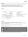
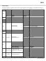
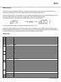
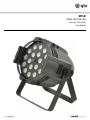
ZP18 ZOOM LED PAR CAN Item ref: 154.018UK User Manual Caution: Please read this manual carefully before operating Damage caused by misuse is not covered by the warranty Introduction Thank you for choosing the ZP18 zoom PAR can as part of your stage lighting equipment. This product is designed to provide bright illumination and vivid colours in various beam angles for stage and theatre shows. Please read these instructions fully in order to gain the best results from this item and avoid damage to the unit through misuse. Unpacking Your ZP18 should reach you in good condition and should be supplied with IEC mains lead(s) If there are any signs of damage or items missing from the packaging, contact your dealer immediately. Warning To prevent risk of fire or electric shock, do not expose electrical parts to rain or moisture. If any liquids are spilled on the ZP18, allow it to dry out and have it checked by qualified service personnel before further use. Avoid any impact, dropping or extreme pressure to the housing. No user serviceable parts inside - do not open the case. Allow the ZP18 to acclimatize to room temperature before operating. Refer all servicing to qualified service personnel. Safety Symbol and Message Conventions CAUTION RISK OF ELECTRIC SHOCK DO NOT OPEN AVIS RISQUE DE CHOC ELECTRIQUE NE PAS OUVRIR This symbol indicates that dangerous voltage constituting a risk of electric shock is present within this unit This symbol indicates that there are important operating and maintenance instructions in the literature accompanying this unit. Safety Check for correct mains voltage and condition of the IEC lead before connecting to a power outlet Check the condition of DMX control leads before connecting to a controller This unit can produce very bright output. Do not look directly into the LEDs whilst powered up. This unit must be earthed Cleaning Use a soft dry or slightly damp to clean the casing Do not use strong solvents for cleaning the unit 154.018UK User Manual Placement The ZP18 has a built-in dual “U” bracket, which can allow the can to be free standing or fixed to trussing. If free standing, ensure that the ZP18 is positioned on a stable, non-slip surface. If mounted at height onto a truss or stand, it is advised to use a drop wire for additional safety. Allow adequate space for access to the controls and to avoid straining cables and connections. Rear Panel 1. DMX out XLRF connector 2. LED digit display 3. Control panel 4. Mains inlet wire (terminates to IEC male) 5. DMX in XLRM connector 6. Mains fuse 5 x 20mm F3A 250V Setting Up The ZP18 has a hard-wired lead with an in-line IEC plug for mains power connection (4) Connect to a mains outlet using the supplied IEC mains lead, ensuring that the voltage and current capacity are correct for powering the ZP18. The ZP18 can operate as a stand-alone item from internal programs or from DMX512 signal. Standalone modes are shown below. Mode STAT AUTO SOUd RUN Details Static colour with strobe and zoom options AT01-AT10 Built-in auto preset sequences PR01-PR10 Stored user programmable sequences 2 sound-activated modes DMX enables control from a DMX512 signal SLAV sets the fixture to mimic a standalone ZP18 connected to the DMX input The setup of the fixture is accessed via the onboard menu as shown on the next page. 154.018UK User Manual Onboard Menu The various modes of operation of the ZP18 can be set using the control panel (2) and digital LED display (3) MODE STAT AUTO SOUd RUN dMX ENTER R G B W ST M AT** PR** Mod* **** d.001 DMX personality (channel mode) PERS Id TEMP EDIT Id.** CURR TOP Fixture ID number Current temperature Max temp (before cut-out) PR01-PR10 Edit programs Scenes SC00 to SC30 Upload Restore/Reset ID mode RGBW mode Power output mode Dimmer curves mode SET CAL1 WT.01-WT.11 CAL2 RGBW KEY Function Red Green Blue White Strobe Zoom Auto programs User programs Sound mode Control mode Start address Calibrate white colour temperatures for STAG mode ch.6 Calibrate RGBW limits Lock display after 30s inactivity UP/DOWN 000-255 000-255 000-255 000-255 000-255 000-255 AT01-AT10 PR01-PR10 MOd1-MOd2 dMX-SLAV. 001-255 STAG ARC.1 AR1.d ARC.2 AR2.d AR2.S HSV Id01 – Id66 *** (°C) 020-150 (°C) R.000 - R.255 G.000 - G.255 B.000 - B.255 W.000 - W.255 ST.00 - ST.20 T.000 - T.255 F.000 - F.255 M.000 - M.255 UPLd REST ID RGBW POW dIM R.000 - R.255 G.000 - G.255 B.000 - B.255 W.000 - W.255 R.000 - R.255 G.000 - G.255 B.000 - B.255 W.000 - W.255 ON/OFF ENTER 13 channel Stage mode 5ch architectural RGB 6ch architectural RGB + dimmer 6ch architectural RGBW 7ch architectural RGBW + dimmer 8ch architectural RGBW + strobe Hue/Sat/Level mode ID number for group DMX control Displays current temperature Fixture will cut out at max temperature Red level Green level Blue level White level Strobe frequency (0-20Hz) Time duration Fade time Zoom (10°-60°) Enter passcode to upload PR01-10 Enter passcode to reset the fixture ON (ch11 in STAG mode) - OFF (normal) ON (levels set by CAL2) - OFF (normal) HIGH-NORM OFF/dIM1-4 ON (locked after 30s) – OFF (unlocked) 154.018UK User Manual DMX operation If the ZP18 is to be operated by DMX512, connect the signal from the controller to the DMX input XLR (1). Continue the DMX signal onto further lighting fixtures from the DMX output XLR (5) To control from DMX512, it is necessary to set the DMX start address via the control panel and display (2 & 3) Press the MENU button until the display shows “dMX”, then press the ENTER button. The display will show “d.” followed by a number from 1 to 512, as shown below… In the example shown above, the DMX start address would be “001”. There are 7 different DMX channel modes in total, which are selected in the “PERS” (DMX personality) menu, Details of these are shown below. It is important to select the most appropriate DMX channel mode depending on how the ZP18 is to be controlled and how many DMX channels it can occupy. STAG mode Ch Value Function 1 000-255 Master dimmer 2 000-255 Red (or step time if PR01-PR10 active) 3 000-255 Green (or fade time if PR01-PR10 active) 4 000-255 Blue 5 000-255 White 000-005 No function 006-020 High Power (only when in Normal Power mode) 021-030 No function 031-255 Colour (see colour list below) 000-010 No function 011-255 Strobe function (slow to fast) 000-020 No function 021-120 AT01-AT10 (each +10 value increments preset by 1) 121-220 PR01-PR10 (each +10 value increments program by 1) 221-255 No function 000-255 Auto program speed (only for Auto 1 - 10 presets) 000-009 Preset dimmer speed from display menu 010-029 Linear dimmer 030-069 Dimming curve 1 (fast) 070-129 Dimming curve 2 (medium-fast) 130-189 Dimming curve 3 (medium-slow) 190-255 Dimming curve 4 (slow) 000-009 No function 010-209 ID01 - ID20 (each +10 value increments ID by 1) 210-255 ID21 - ID66 (each +1 value increments ID by 1) 12 000-255 Zoom 10° to 60° 13 000-255 Zoom speed (slow to fast) 6 7 8 9 10 11 154.018UK User Manual HSV mode Ch Value Function 1 000-255 Hue (colour) 2 000-255 Saturation (0-100%) 3 000-255 Value (brightness) 4 000-255 Zoom 5 000-255 Zoom speed (slow to fast) ARC.1 mode Ch Value Function 1 000-255 Red 2 000-255 Green 3 000-255 Blue 4 000-255 Zoom 5 000-255 Zoom speed (slow to fast) AR1.d mode Ch Value Function 1 000-255 Master dimmer 2 000-255 Red 3 000-255 Green 4 000-255 Blue 5 000-255 Zoom 6 000-255 Zoom speed (slow to fast) ARC.2 mode Ch Value Function 1 000-255 Red 2 000-255 Green 3 000-255 Blue 4 000-255 White 5 000-255 Zoom 6 000-255 Zoom speed (slow to fast) AR2.d mode Ch Value Function 1 000-255 Master dimmer 2 000-255 Red 3 000-255 Green 4 000-255 Blue 5 000-255 White 6 000-255 Zoom 7 000-255 Zoom speed (slow to fast) 154.018UK User Manual AR2.S mode Ch Value Function 1 000-255 Master dimmer 2 000-255 Red 3 000-255 Green 4 000-255 Blue 5 000-255 White 000-010 No function 011-255 Strobe (slow to fast) 7 000-255 Zoom 8 000-255 Zoom speed (slow to fast) 6 Colour List (for ch.6 in STAG mode) 031-050 R 100% / G↑ / B 0% / W 0% 051-070 R↓ / G 100% / B 0% / W 0% 071-090 R 0% / G 100% / B↑ / W 0% 091-110 R 0% / G ↓ / B 100% / W 0% 111-130 R↑ / G 0% / B 100% / W 0% 131-150 R 100% / G 0% / B ↓ / W 0% 151-170 R 100% / G↑ / B↑ / W 0% 171-190 R ↓ / G↓ / B 100% / W 0% 191-200 R 100% / G 100% / B 100% / W 100% 201-255 Colour temperature (adjustable by CAL1) 201-205 3200K 206-210 3400K 211-215 4200K 216-220 4900K 221-225 5600K 226-230 5900K 231-235 6500K 236-240 7200K 241-245 8000K 246-250 8500K 251-255 10000K Note: In STAG mode, channel 6 controls colour via a single fader with 11 different white colour temperatures available. The RGBW values of these white shades can be adjusted in the CAL1 calibration menu. Programming User Sequences PR01-PR10 are user sequences that can be programmed in the EDIT menu and stored onboard the ZP18. Press MENU until EDIT is displayed and select the program to be edited. Starting at SC01, set values for RGBW, strobe, time, fade and zoom, move onto the next scene and repeat the process. Escape the EDIT menu by pressing the MENU key and the sequence will be stored internally. Programs PR01-PR10 can be played back via the AUTO menu. 154.018UK User Manual Master/Slave Operation Connect a DMX lead from a standalone ZP18 unit to further slave units and set each slave to “SLAV” in the RUN menu. The slave units will now mimic the standalone “master” ZP18 fixture. Passcode Key and SET menu functions The KEY setting in the menu sets a lock for the display. When set to “ON”, the display will lock after 30s of inactivity. To unlock the display, enter the passcode – UP-DOWN-UP-DOWN-ENTER The passcode is also used for UPLd and REST functions in the SET menu as shown below. UPLd REST ID RGBW POW dIM Enter passcode (UP-DOWN-UP-DOWN-ENTER ) to upload PR01-10 programs to a connected slave fixture Enter passcode (UP-DOWN-UP-DOWN-ENTER ) to reset the fixture When set to “ON”, allows fixture to be controlled in groups in STAG mode determined by the ch11 setting When set to “ON”, the max levels of R, G, B, W outputs are set by CAL2 to achieve balanced white output Determines whether the output is set to Normal or High power 4 dimming curves can be set to vary the fading profile of Specifications Power supply Power consumption Fuse rating LED type Beam angle DMX channels DMX connection Dimensions Weight LED safety standard 110-240Vac, 50/60Hz (IEC) 150W F3A, 250V 18 x 8W (4-in-1 quad colour) 10° - 60° Dimmer, R, G, B, W, Zoom, Strobe XLRM in, XLRF out 263 x 215 x 250mm 2.85kg BSEN62471:2008 Troubleshooting No light output and no display Display on but no light output No response to DMX Check mains voltage is correct and socket is switched on Check IEC lead is OK and connected properly Check mains fuse on rear panel and fuse in plug top If fuse blowing repeatedly, refer to qualified service personnel Check operation mode (DMX, standalone) Check static and colour settings are not all set to zero or slow fade For DMX operation, check the appropriate Personality mode is set Check if a static or user program is set with zero light output Check that XLR leads are connected properly Check that DMX signal is OK by testing on other equipment Check that correct address is set in the menu Ensure that mode is set to DMX and not Slave Disposal: The “Crossed Wheelie Bin” symbol on the product means that the product is classed as Electrical or Electronic equipment and should not be disposed with other household or commercial waste at the end of its useful life. The goods must be disposed of according to your local council guidelines Errors and omissions excepted. Copyright© 2015. AVSL Group Ltd. 154.018UK User Manual