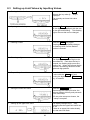
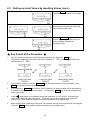
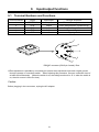
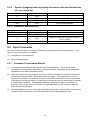
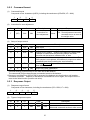
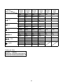
1
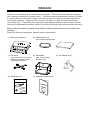
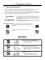
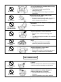
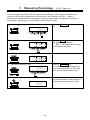
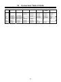
200046M11 High-Precision Tuning Fork Electronic Balance AJ-NT/DBNT Series Operation Manual IMPORTANT • To ensure safe and proper use of the balance, please read this manual carefully. • After reading this manual, store it in a safe place near the balance, so you can review it as needed. SHINKO DENSHI CO., LTD. PREFACE Thank you for purchasing an AJ Series electronic balance. This is a precision instrument equipped with exacting mechanisms in a compact body. The AJ series provides enhanced functions, including a counting mode for stock control of parts, and a limit function for measuring constant quantities by consecutive weighings. Despite its many functions, the balance is easy to operate and features user-friendly keys. Furthermore, the large liquid-crystal display provides excellent visibility, and the instrument’s high speed and stability−intrinsic to a tuning fork design−help boost operational efficiency. Before using the balance, please check that the following items have been included in the package. Should you find any missing parts, please contact our local dealer. (1) Main unit of balance ON/OFF P S F (2) Measurement pan (one round or square pan) 0 (4) Windshield (3) Pan base (one for round-pan (one small for the round-pan balance only) balance; one large for the square-pan balance) (6) DIN5P plug set (7) Operation manual (one) (5) AC adapter (one) CONTENTS 1. 2. 3. 4. 5. 9. Precautions on the Use .................... 2 1.1 Warnings regarding Use................ 2 9.1 Terminal Numbers and Functions.......31 1.2 For More Precise Measurements .. 5 9.2 Connection between Balances and Personal Computers........................32 Names of Component Parts ............. 8 2.1 Main Unit ....................................... 8 9.3 Interface Specifications ......................33 2.2 LCD Indicators and Operating 9.4 Output Data ........................................34 Keys .............................................. 9 9.5 Input Commands ................................36 10. Basic Operations .............................11 Operating the Balance with the 3.1 Installation ....................................11 Battery ....38 3.2 Operation Check ......................... 13 10.1 Specifications ...................................38 3.3 Operation for Zero Adjustment .... 14 10.2 Charging Method..............................38 Functions......................................... 16 10.3 User Precautions..............................38 4.1 Setup and Checking of Functions 16 4.2 Description of Functions.............. 17 4.3 Interface Section ......................... 18 11. Operating the Balance with the Dry Cell Battery (DBNT) .....................39 Switching Function for Unit of Measurement.... 19 6. Input/output functions ........................31 5.1 Switching Units of Measurement. 19 5.2 Setup of Units of Measurement . 19 12. Troubleshooting ................................40 13. Specifications ....................................41 13.1 Basic Specifications..........................41 13.2 Common Specifications....................42 13.3 Capacities and Minimum Indications Counting Pieces.............................. 21 6.1 Sampling ..................................... 21 6.2 Increasing the Counting Accuracy for Different Indication Units ............43 14. (Memory Update Method) ........... 23 7. Measuring Percentage (AJ-NT only) .. 24 8. Limit Function ................................. 26 8.1 Limit Function Setup.................... 26 8.2 Setup of Limit Values by Actual Quantity Loads............................ 28 8.3 Setting up Limit Values by Inputting Values .......................... 29 1 Conversion Table of Units ................44 1. 1.1 Precautions on the Use Warnings regarding Use • This Section "Precautions Relating to Use" sets forth precautionary notes that the user should observe in order to prevent physical injury to the user and/or damage to property. • The nature of problems that may result in the event of improper operation, and consequential effects on the quality and performance of the balance, are indicated under the two categories of "Caution" and "Recommended," and explained using symbols. ! CAUTION 注 意 RECOMMENDED This symbol indicates a risk of injury or property damage if the balance is used improperly. Be sure to observe these notes to ensure safe use of the balance as the improper use may cause serious results. This term indicates steps that the user should take to ensure the quality and reliability of the balance. Meanings of Symbols Each symbol is accompanied by an instruction. Indicates a “mandatory” action that should be executed without fail. 水平確認 Check Level 強制記号 Mandatory Symbol: Indicates a "prohibited" action that must not be executed. Do not Use 使用禁止 Prohibitive 禁止記号 Symbol: ! CAUTION 注 意 Do not disassemble or modify the unit. • Could cause malfunction or heat generation • Contact our local dealer. Do Not 分解禁止 Disassemble Only AC power (rated value) should be used. Only use the dedicated AC adapter. • Use of other types of power or adapters may result in heat generation or malfunction of the balance. 定格外禁止 Do Not Deviate from Ratings Do not move the balance when a sample is loaded. • The loaded sample may fall off the measurement pan and cause an injury. Do移動禁止 Not Move 2 Do not place the balance on an unstable base or use the balance in a location where it may be subjected to shock. • The loaded sample may fall off the measurement pan. • Accurate measurement may be rendered impossible. 定格外禁止 Do Not Use Do not lay the AC adapter cable on the surface of the passage. • Somebody may trip on the cable, causing the balance to fall off, thereby causing injury and/or damage to the balance. 定格外禁止 Do Not Drop Do not touch the AC adapter or balance with wet hands. • Danger of electric shock Do定格外禁止 not Handle with Wet Hands Do not use the balance in a location were it may be subjected to excess moisture. • Electric shock or short-circuiting could occur. • The balance may be corroded, with resultant malfunction. 定格外禁止 Keep Dry Do not use the balance with its adjusters lifted. • The balance will become unstable, preventing accurate measurement. 定格外禁止 Do Not Leave Afloat Do not use the balance in a location where it may be subjected to excess dust. • Risk of explosion or fire • Short-circuit or lack of continuity may occur, leading to a malfunction of the balance. 定格外禁止 Avoid Dust RECOMMENDED Avoid applying excess force or impact to the balance. Place the sample to be measured on the balance carefully to prevent breakage or malfunction. 定格外禁止 Do Not Apply Force Do not use the balance in a location were it may be subjected to abrupt changes in ambient temperature or humidity. • Accurate measurement may not be obtained. 定格外禁止 Do Not Use • Optimum operations occur when ambient 3 Do not use the balance when [o-Err] (Overloaded) is displayed. • Take down the loaded sample immediately to prevent breakage or malfunction. 定格外禁止 Do Not Overload Do not use the balance in a location where it is subject to direct sunlight. • The indications would be illegible. • An internal temperature increase in the balance may lead to inaccurate measurement. 定格外禁止 Do Not Use If the balance is to be unused for an extended period of time, unplug the adapter. • This conserves power and prevents deterioration. Unplug Adapter Do not use volatile solvents for cleaning. • The body may be distorted. • To clean the unit of stains, use a piece of dry cloth or cloth soaked in a small quantity of neutral detergent. 定格外禁止 Do Not Use Do not use the balance in a location where it may be subject to air from an air-conditioning unit. • Extreme changes in the ambient temperature may result in inaccurate measurements. 定格外禁止 Do Not Use Do not use the balance on a soft floor. • When loaded with a sample, the balance may tip or move, preventing accurate measurements from being conducted. 定格外禁止 Do Not Use Do not use the balance when it is tilted. An inclined balance is likely to produce errors, preventing accurate measurements from being conducted. Place the balance on a level surface. Check Level 4 1.2 For More Precise Measurements To be able to conduct more precise measurements, it is necessary to minimize the factors that contribute to measurement errors. There are a great variety of such error-inducting factors, which can be linked to machine error and performance of the balance itself, as well as the properties and condition of samples being measured, and the measuring environment (e.g., vibration, temperature/humidity). These factors can readily affect the results of measurement on a balance that has high resolution readability. This material includes some precautionary notes that the user should bear in mind to eliminate error factors and ensure accurate measurement results. 1-2-1 Precautions on the Measuring Room Temperature / Humidity → → Vibration/ Shaking → Drafts → Gravity → Electromagnetic Waves → Try to maintain constant room temperature as much as possible to prevent dew condensation and unstable indications due to fluctuations in temperature. Low relative humidity tends to induce static electricity,causing measurement error. (Relative humidity of about 60% is considered ideal.) The measuring room should preferably be located on the ground floor or in the basement. Higher floors are more susceptible to heavy vibration and shaking, which make such locations less suitable for measurement. A room facing a railway or road with heavy traffic should also be avoided as much as practicable. Avoid choosing a location subject to a direct draft of airflow from an air-conditioning unit or exposed to direct sunlight, which may cause unstable reading due to abrupt fluctuations in temperature. Also avoid a room subject to a heavy flow of people, since fluctuations in drafts and temperature are likely to occur in such a location. The gravity acting on a sample varies depending on the latitude or height of the location where measurement is being conducted. For this reason, the same sample may show different weight indications from one place to another. Therefore, make it a rule to calibrate the balance every time it is relocated. When the balance is located near an object that generates intense electromagnetic waves, it may be hindered from showing accurate weight due to the effects of such waves. Therefore, avoid placing the balance in such a location. 5 1-2-2 Precautions on the Measuring Bench Vibration/ Shaking → → Magnetism/ Static Electricity 1-2-3 → If the balance is subjected to vibration during measurement, its indications will become unstable, thus preventing accurate measurement from being conducted. To avoid this situation, select a solid measuring bench that is less susceptible to vibration. (A bench in a vibration-proof structure or one made of concrete or stonework will be suitable.) Moreover, do not conduct measurement with a soft cloth or paper placed under the balance, since the balance may be rocked out of its precise level positioning. Place the measuring bench in a location free from vibration as much as possible. It is a good idea to install the measuring bench in a corner of the measuring room, where less vibration is likely to occur than in the center of the room. Avoid operating the balance on a bench that is susceptible to the effects of magnetism or static electricity. Precautions on the Samples Static Electricity → Magnetism → Absorption/ Evaporation of Moisture → Sample Temperature → → Generally speaking, objects made of synthetic resin and glass has high electric insulating properties and, therefore, are apt to be electrically charged. Measuring a charged sample as is may cause unstable indications, with resultant poor reproducibility of the results. With this in mind, be sure to discharge charged samples before measurement. A sample affected by magnetism indicates different weight values depending on where it is located on the measuring pan, along with resultant poor reproducibility of the results. When a magnetized sample must be measured, first demagnetize it or place an appropriate pedestal on the measuring pan to adequately separate the mechanism part of the balance from the magnetized sample for avoiding the effects of magnetism. Measuring a sample with moisture absorbed or evaporated (volatized) continuously increases or decreases the values indicated. In such case, measure the sample in a container with a small opening and sealed airtight with a cap. A difference in temperature between a sample and the interior of a windshield may cause convection to occur inside the windshield, resulting in erroneous measurement. Therefore, measure a very hot or cold sample only after allowing time for its temperature to acclimatize to room temperature. Moreover, to prevent convection inside the windshield, allow time for the interior of the windshield to acclimatize to room temperature. The body heat of a person conducting measurement can also affect measurement results. Avoid holding the sample with bare hands, and use long tweezers or a similar tool instead. Also refrain from putting your hands inside the windshield while measurement is in progress. 6 1-2-4 Precautions on the Main Unit of the Balance Precautions on Use → → Calibration Maintenance → A transparent dust cover, supplied for some models, may be statically charged under low humidity conditions, which may cause unstable readinig. In such case, wipe the dust cover with a damp cloth or use a commercial antistatic agent. Otherwise, simply operate the balance with the dust cover removed. For more stable measurement, it is recommended to have 30 minutes warm up time after power-up, and apply a load equivalent to the weighing capacity several times before conducting actual measurement operation. Periodically calibrate the balance with an internal or external calibration weight to ensure accurate measurement at all times. → For more precise calibration, use an external calibration weight that approximates the weighing capacity. Moreover, calibrate the balance only after enough warm up time and loading near capacity weight. → Calibration is also required in the following cases: When operating the balance for the first time, When not using the balance for a long time, When relocating the balance, or When there is wide fluctuation in temperature, humidity or atmospheric pressure. When the measuring pan or pan base is contaminated with powder or liquid, erroneous weight values may result or indications may remain unstable. Therefore, be sure to frequently clean the balance. When cleaning the balance, be very careful not to allow dirt or liquid to penetrate inside (the mechanism part). → 7 2. 2.1 Names of Component Parts Main Unit Capacity(g) Pan type 220~620 Round 820~12K Square Front View (round-pan type) Level For checking the level of the balance Turn the adjusters until the bubble rests in the center of the red circle. Windshield Supplied only with the round-pan types The top lid is detachable. Dry Cell Box ON/OFF P S F (DBNT) 0 Liquid-crystal display (LCD) See page 9. Operation keys See page 10. Rear view Measurement pan RS232C connector Adjusters Round-pan type: Total of two, one on either side of the unit’s front Square-pan type: Total of four, one on either side at front and rear AC adapter connector Square-pan type ON/OFF P S F 8 0 2.2 2.2.1 LCD Indicators and Operating Keys Symbols Displayed HI 0 0 F Pcs # OK g% LO Display Description g Grams →0← ○ 0 Zero point Indication of stable balance (If the light is off, the balance is unstable.) * Pcs % Balance powered up (Lights up when the power is turned off) or data transmitted M CAL Display of set values from memory (If a value is flashing, it is being saved.) Counting mode percentages mode Indication of judgement result (HI/OK/LO) when the limit function is active. Stays on and flashes while span adjustment is in progress. Auxiliary scale interval (Lights up only when the auxiliary scale interval is displayed.) F Bar graph [ [ [ [ [ [ ] (ct) carat ] (oz) ounce ] (lb) pound ] (ozt) troy ounce ] (dwt) pennyweight (Upper right) ] grain It stays on [ ] when operated by rechargeable battery or dry cell battery. ] when the battery capacity becomes low. It flashes [ ( Refer to page 38 or 39.) It does not show when powered by AC adaptor. 9 2.2.2 Names and Functions of Operating Keys Operating Key ON/OFF On/off key P Memory key S Set key F Function key 0 Zero key Function Key to turn on/off the unit power [Brief press] [Brief press] initiates print or output. saves the settings of the number of pieces, or the limit value when using the limit function. [Brief press] starts setting the number of pieces or percentages (%). [Continuous press] starts setting the limit value when using the limit function. [Brief press] toggle-switches the units to be displayed in succession (g, Pcs, etc.). [Brief press] moves the flashing digit in the setup of a limit value when using the value input method. [Brief press] selects an item when setting the function. [Continuous press] invokes various functions. [Longer continuous press] invokes span adjustment. [Brief press] resets the indication to zero when using zero-point setup. [Brief press] selects a value with the value input method when using the limit function. [Brief press] selects a function when operating the balance in the function mode. 10 3. 3.1 1 Installation Positioning the measurement pan ON/OFF 2 Basic Operations P S F First, mount the pan base on the main unit of the balance and place the measurement pan on top of it. Be sure to mount the pan base in the correct direction, as illustrated below. 0 Windshield setting(Capacity 220g~620g only) (1) step (1)Set a small panel in a large panel. An edge with step should face the same side. step (2)Set the other large panel in the assembly above. (2) (3)Set the other small panel in the assembly above. (3) 11 3 Put on the windshield Put the cover on top and place the complete assembly along the guide. ON/OFF 4 P S F 0 Securing the exact level of the balance Turn the adjusters until the bubble rests in the center of the red circle on the level. Round-pan type: total of two adjusters, one on either side at front Square-pan type: total of four adjusters, one on either side at front and rear Position of air bubble in the level ON/OFF 5 P S F <Caution> Use caution when operating the adjusters on the square-pan type to prevent them from lifting up. 0 Connecting the AC adapter Connect the AC adapter to the balance, as illustrated at left. ※Take 5 minutes before operation. <Caution> If the balance has the battery installed, refer to “10. Operating the Balance with the Battery. 12 3.2 Operation Check 1 Turning on the power When the balance has the AC adapter connected, it displays [*]. Pressing the On/Off key The display section lights up, and the balance is ready for operation. * 2 Checking the display 0 0 Pcs # F Check to see if the display has any missing indications or unlit parts. A few seconds after startup, the indication is reset to zero. g% 3 Switching the measurement mode Press the Function key. Each time the key is pressed, the unit of measurement changes, as indicated. ※The balance is shipped from the factory with the following switching sequence: [g] → [ct] → [Pcs] → [g] →··· 4 Verifying changes in the read-out indicator Press the measurement pan lightly and make sure that the read-out indicator changes. Also, ensure that the read-out indicator is reset to zero when you release your hand. 13 3.3 Operation for Zero Adjustment 1 Place the container on the balance. As you place the container, the balance indicates its weight. 2 Reset read-out indication to zero. Press the Zero key. The container is subtracted and the balance indicates zero. 3 Load the sample to be weighed. The balance will now indicate only the weight of the sample loaded in the container. ☆ Weighing only the weight of an added sample 4 Resetting the indication to zero Press the Zero key. The total weight of the sample loaded on the measurement pan is indicated as zero. 5 Adding samples to be measured The balance indicates only the weight of an added sample. When the weight (of a sample) currently loaded on the measurement pan is reset to zero with the Zero key, as mentioned above, only the weight of the sample will be measured. 14 ☆ Key Points of the Procedure ☆ The following applies equally to all the measurement modes for weight measurement, counting, and percentages. 1. 2. After the balance is switched off, there is still enough current to display [*]. This indicates that the AC adapter is connected to an electrical outlet, but that the balance is turned off. When the balance is switched on again, [*] will disappear. ※If the balance is running on batteries and the unit is switched off, the display does not display [*]. The bar graph shows the current load status with respect to the capacity of the balance. The nearer the [F] mark draws, the smaller the measurable weight becomes. ※Even when the display currently indicates zero with the weight subtracted, the weight corresponding to the gross value is indicated on the bar. Zeropoint ゼロ点 Capacity point ひょう 0 F Half (1/2) capacity ひょう量の1/ 3. When the balance remains stable, the stability indicator [○] remains on. If the balance becomes unstable, the stability indicator [○] will disappear. When a displayed value flickers or the stability mark flashes on and off, it is likely that the balance is being affected by wind or other vibrations. Use the windshield or vibration dampers to protect against such adverse effects. 4. When the read-out indicator is reset to zero, the balance indicates zero this way: [→ 0 ←]. 5. Only weight fraction that was canceled, the measurable range is reduced. Measurable Range = Capacity – container weight. 6. If [o-Err] appears when a sample is loaded, the measurable range has been exceeded. 7. In counting mode, if no sample is stored in memory the indicator will not change, even when the measurement pan is pressed. 8. The measurement mode that is activated when the balance is switched on will be the one that was active when last switched off. For example, if the balance was switched off in counting mode, this counting mode will be reactivated the next time the balance is switched on. 15 4. 4.1 Functions Setup and Checking of Functions 1 Invoking the function Press and hold down the Function key until the indicator changes to “Func,” then release the key. The function setup mode is activated, and the first item, [1. b.G. 1 (Bar graph) 1] appears. (See “4.2 Description of Functions” on page 17.) 2 Selecting the next item Press the Function key. The indication changes to the next item, [2.SEL 0 (Limit function)]. 3 Selecting an item Pressing the Function key advances the function items at the rate of one item per press. 4 Changing the content of an item Select the item to be changed with the Function key. Each press of the Zero key changes the digit on the right end. Select the desired one. 5 Terminating the function selection Press the Set key. The balance terminates the function setup and returns to measurement mode. 16 4.2 Description of Functions Item Set Value 1. b.G. Limit function 2.SEL Displayed only when limit function is activated Bar graph display Description 0 ☆1 ☆0 1 ☆1 Judgement condition 21.Co. Judgement range 22.Li 2 0 ☆1 Number of points for judgement 1 23.Pi ☆2 0 Auto power-off 4. A.P. ☆1 Response speed 5. rE. Interface 7. I.F. Setup of units of measurement to be displayed Register selected measuring units with Function key. 81.S.u. | 85.S.u. 0 1 2 ☆3 4 5 ☆6 0 ☆1 2 ☆1 01 ☆2 14 15 16 17 18 19Ú1 Disable Enable Disable Enable Always judge (judges even when the balance is unstable) Judge only when the balance is stable (does not judge if the balance is unstable) Ranges beyond +5 graduation is judged (ranges +5 graduation or below, including negative ranges, are not judged.) The entire range is judged (the entire range, including the negative, is judged). One-point setup (judges between OK and LO) Upper-limit and lower-limit values are set up (judges among HI, OK and LO). Disable (balance operates This function is continuously) available only when Enable (balance powers off the balance is battery-operated. in approximately three minutes) Measurement by consecutive weighings. Fast ↓ Slow Disable input/output Six-digit numeric format Seven-digit numeric format [g] [ [ [ [ [ [ ] (ct) ] (oz) ] (lb) ] (ozt) ] (dwt) Lower right ] (grain) 20 [Pcs] 1F [ % ] ☆4,5 00 Unit not set Items mrked ☆ are the default factory settings. ☆1~☆5: default factory settings [81.S.u.]~[85.S.u.] ☆6: AJ-NTDB Type only ※ 1 For 220g~6200g Capacity model ☆3 17 4.3 Interface Section Displayed when [7. Item I.F. ] is set to [1] or [2] Set Value Output Control 71. o.c. Baud Rate 72. b.L. Parity 73. PA. Description 0 Stop output 2 Output continuous if stable (stop output if unstable) Outputs once if stable. Outputs if the balance is stable when a sample is loaded after the preceding sample 4 has been removed and the balance indicated zero, or less. Outputs once if stable, and stops output when unstable. Even if the sample is not replaced, the balance is output 5 once when it stabilizes next time (including the zero indication). Pressing Memory key causes the balance to output ☆7 once when stable. ☆1 1200 bps 2 2400 bps 3 4800 bps 4 9600 bps ☆0 None Displayed only when [ 7. I.F. 2 ] 1 Odd (7-digit numeric format) is specified. 2 Even ☆ denotes a factory-setting 18 5. 5.1 Switching Function for Units of Measurement Switching Units of Measurement Pressing the Function key allows the user to switch the unit of measurement to [g], [ct] and so on. Switching the units of measurement to be displayed g Pcs 5.2 Press the Function key. Each press advances through the units of measurement to be displayed. ※The balance is shipped from the factory with the following default setup: [g] → [ct] → [Pcs] → [g] →··· Setup of Units of Measurement When values [81.S.u.] to [85.S.u.] are entered prior to use, the desired unit of measurement to be displayed can be chosen simply by pressing the Function key. For more information on the units of measurement that can be set here, please refer to “4.2 Description of Functions” on page 17. Example: To change the default factory settings to pound units, use [82.S.u.] . 1 Display the function item [82.S.u. 14] Press and hold down the Function key. Release the key as [Func] appears on the display. The function setup mode is now activated and the first item is displayed. Press the Function key several more times, until [82.S.u. 14] appears. 2 Setting the unit to a pound Press the Zero key several times to specify [82.S.u. 16]. 19 Example: To change the default factory settings to pound units use [82.S.u.] . (cont.) 3 Pressing the [Set] key to restore measurement mode. Pressing the Set key will reset the measurement mode 4 Pressing the [Function] key to change the units of measurement Press the Function key. Each press of the key changes the units of measurement to be displayed, as follows: [g] → [lb] → [Pcs] → [g] → · · · ☆ Key Points of the Procedure ☆ 1. When set values are entered in the function items [81.S.u.] to [85.S.u.] prior to use, the desired unit of measurement to be displayed can be selected simply pressing the Function key. For more information on the units of measurement that can be set, please refer to “4.2 Description of Functions,” on page 17. 2. The units are displayed in the same sequence as the settings made from [81.S.u.] to [85.S.u.]. 3. If [00] is set, no unit of measurement will be displayed, even when units of measurement are set in subsequent items. 4. [00] cannot be set in [81.S.u.]. 5. If the same unit of measurement is set multiple times, the second time (and all subsequent times) the unit(s) occurs, it will be ignored when the display switches. 20 6. Counting Pieces To implement piece-counting, the specified samples are loaded on the balance, and their average unit weight (hereinafter, simply the “unit weight”) is entered and saved. The procedure for saving unit weights is called sampling. The counting procedure consists of loading articles that have already been sampled on to the balance. The number of pieces is then calculated by dividing the total weight of the loaded articles by the unit weight saved in memory. Piece counting cannot be implemented unless sampling has already taken place. Sampling Counting Pieces 500 g Total weight = = 500 pcs. Sample unit weight 1g 10 g Weight = =1g Number of samples 10 pieces = Measured number of samples =Sample unit weight ※If samples to be counted deviate widely in weight, or a higher measure of accuracy is desired, it is recommended that users use the “Raising the Counting Accuracy” method. This procedure results in greater precision by increasing the number of samples used in the sampling operation. 6.1 Sampling 1 Activating the counting mode Press the [Pcs]. 2 Resetting the indication to zero Place the container and press the Zero key. The container is subtracted and the balance now indicates zero. 3 Starting the sampling Press the Set key. The display flashes a number, such as [ on 10 ]. This means that ten samples are to be loaded. The sampling number that was used in the previous sampling will be displayed here. 21 Function key to display 4 Changing the sampling number, if necessary. 5 Loading samples 6 Saving the unit weight of samples If samples to be counted widely deviate in weight, or a higher measure of accuracy is desired, it is recommended that users change the sampling number to a larger value. Press the Zero key. Each press of the key changes the value on the right end. Select the desired value. If the sampling number need not be changed, go on to the next step. Load the number of samples displayed. Count the samples precisely and load them in the center of the measurement pan. Press the Memory key. The balance saves the unit weight and reverts to measurement mode. ☆ Key Points of the Procedure ☆ 1. While the samples are being saved, the value indication disappears and only [M] flashes to indicate that memory saving is underway. If the balance is affected by wind or other vibrations during this process, the saving time may be prolonged. 2. If [L-Err] appears, it indicates one of the following states: (1) The weight of one sample (measurable unit weight) is insufficient. For the range of unit weights that can be measured and saved, please refer to “13. Specifications,” on page 41. (2) In the sampling of Operation Step 3, press the balance. Set key with the samples loaded on the ※ If [L-Err] appears, the sampling is interrupted and the data in progress is not saved. 3. The operation for increasing counting accuracy is referred to as the Memory Update Method. This procedure updates the memory with a unit weight that represents a more precise average by gradually increasing the sampling number. This operation improves counting accuracy and is recommended for the following cases; (1) When the samples to be counted deviate widely in weight or the number of samples displayed deviates. (2) When greater accuracy is desired. 4. If [Add] appears in Memory Update Method, it indicates that a counting error is likely due to the ] will light up at the judgment small number of the samples loaded on the balance. [ indication “LO.” As the memory update continues, counting accuracy improves and the above indication disappears. 5. If you change the sampling number, subsequent sampling will start from the new sampling number. 22 6.2 Increasing the Counting Accuracy (Memory Update Method) ※This procedure is the same as the sampling procedure described on the previous page up, to the point at which the sampling number is changed. 1 Loading samples Load the number of samples displayed. Count the samples precisely and load them on to the center of the measurement pan. 2 Saving the samples Press the Set key. The unit weight of the samples is saved, and the display changes to a flashing value. This flashing value denotes that the Memory Update Method is currently active. 3 Adding samples Add approximately an equal number of samples as the number currently displayed. Add them gradually, in groups of approximately the same number, until the number of samples is approximately double. The additional samples need not be counted. 4 Saving the samples Press the Set key. After the unit weight of the samples has been saved, the display begins to flash, indicating that the Memory Update Method is still running. 5 Repeating the addition and saving of samples Repeat steps 3 and 4. The eventual total number of samples to be saved should be approximately 1/5 to 1/2 of the number of samples to be measured. 6 Terminating the sampling Press the Memory key. The balance saves the unit weight and returns you to measurement mode. 23 7. Measuring Percentage (AJ-NT Type only) The percentage measurement function operates by weighing an actual sample, selected as the reference, and saving its weight as the reference value and indexing it as 100%. When a measurement sample loaded on the balance is lighter or heavier than the reference, its weight is indicated as a percentage (%) value relative to the reference weight. 1 Activating the percentage mode Press the [%]. Function key to disaplay % 2 Setting the reference value % 3 Loading the sample Press the Set key. The display begins flashing [P. SEt]. The balance is now ready for reference value setup. Load the reference sample. % 4 Saving the reference value % 5 Press the Memory key. The balance indexes the weight value of the reference sample as 100% and returns you to measurement mode. The balance now indicates the weight of the loaded sample as a percentage (%) value relative to the reference value. Loading a sample to be measured % 24 ☆ Key Points of the Procedure ☆ 1. While samples are being saved, the value indication disappears temporarily, and only the [M] mark flashes. If the balance is affected by wind or other vibrations during this process, the saving time may be prolonged. 2. If [L-Err] appears briefly, it indicates one of the following states: (1) The weight of the reference sample is insufficient. For the limit weight that can be saved (% limit weight), please refer to “13. Specifications,” on page 41. (2) While setting up the reference value in Step 2, the samples were loaded on the balance. Set key has been pressed while the ※If [L-Err] appears, sampling has been interrupted and the sample value being processed will not be saved. 3. The minimum intervals between percentages in the unit switch from 1%, to 0.1%, to 0.01%, depending on the reference weight from the sampling. 25 8. Limit Function The limit function judges measurements according to a limit value saved in the balance. ] mark as either HI (excessive), OK The function shows the judgement result by displaying the [ (appropriate), or LO (insufficient). This function is very useful when discriminating between conforming and nonconforming articles. It is also useful when measuring a given constant quantity consecutively, in conjunction with a range of reference weights defined by upper- and lower-limit values. This function can be used in weight mode, counting mode, or percentage mode. Limit value input methods Either of the following two methods can be used in the different modes: (1) Actual quantity setup method ........ An actual sample is loaded on the balance and its weight saved as the limit value. (2) Numeric value setup method ......... The limit value is entered with a key stroke. ※The limit values entered are held in memory, even when the balance is powered down. ※The respective limit values for weight mode, counting mode, and percentage mode are set up independently. Indication of judgement result The [ ] mark lights up as either HI, OK, or LO on the left side of the display, indicating the result of judgement. Judgement Results HI (excessive) OK (appropriate) LO (insufficient) 8.1 1 Upper/lower-limit setting Upper-limit value < measurement value Upper-limit value ≥ measurement value ≥ lower-limit value Lower-limit value > Measurement value One-point setting No indication Limit value ≤ measurement value Limit value > Measurement value Limit Function Setup Invoking the function Press and hold down the Function key. Release the key when [Func] is displayed. The display changes to the function setup and the first item is displayed. 26 8.1 Limit Function Setup (cont.) 2 Selecting a function item Press the Function key. The display changes to the next item [Limit Function]. 3 Setting the limit function Press the Zero key to set the value on the rightmost side to [1]. 4 Setting the judgement condition Press the Function key. The display changes to [Judgement Condition]. Press the Zero key to select the desired condition. 5 Setting the judgement range Press the Function key. The display changes to [Judgement Range]. Press the Zero key to select the desired choice. 6 Setting the number of judgement points Press the Function key. The display changes to [Judgement Points]. Press the Zero key to select the desired choice. 7 Terminating the function setup Press the Set key. The balance terminates the function setup and returns you to measurement mode. 27 8.2 Setup of Limit Values by Actual Quantity Loads 1 Starting the limit function Press and hold down the Set key. Release the key when [ L. SEt ] is displayed. The currently set lower-limit value flashes. 2 Loading the sample for the lower-limit value Load the sample of the lower-limit value on the measurement pan. 3 Saving the lower-limit value Press the Memory key. After the lower-limit value has been saved, the balance displays it briefly and proceeds to the following setup. ※If One-point setup was chosen, the setup is complete. 4 The upper-limit value setup The display now changes to [ H. SEt ], indicating that the upper-limit value can be set. The currently set upper-limit value flashes. 5 Loading the sample of the upper-limit value Load the sample of the upper-limit value on the measurement pan. 6 Saving the upper-limit value Press the Memory key. After saving the upper-limit value, the balance displays it briefly and terminates the setup. 28 8.3 Setting up Limit Values by Inputting Values 1 Starting the limit function Press and hold down the Set key. Release the key when [L. SEt] is displayed. The currently set lower-limit value flashes. 2 Opening the value input screen Press the Zero key. All the digits are displayed, with the one on the right end flashing. This flashing digit is the one that can be changed. 3 Entering a value Press the Zero key again. Pressing the key repeatedly changes the flashing value until the desired number is entered. 4 Selecting a digit Press the Function key. The flashing moves to the digit on the immediate left. Each time the key is pressed, the flashing digit moves one position left. When the leftmost digit is selected, the flashing advances to the rightmost digit position. 5 Repeat Steps 3 and 4 Enter the lower-limit value by selecting a value with the Zero key and moving the digits with the Function key, as needed. 6 Saving the lower-limit value Press the Memory key. After saving the lower-limit value, the balance displays it briefly and proceeds to the next setup. ※If one-point setup was chosen, the setup is complete. 7 Setting up the upper-limit value The display changes to [H. SEt], indicating that the upper-limit value can be set. If there is an upper-limit value already set, that value will flash. 29 8.3 Setting up Limit Values by Inputting Values (cont.) 8 Opening the value input screen Press the Zero key. Follow the same procedure as in “Step 2.” 9 Setting the upper-limit value Follow the same procedure as described for the lower-limit value and enter the upper-limit value. 10 Saving the upper-limit value Press the Memory key. After saving the upper-limit value, the balance displays it briefly and terminates setup. ☆ Key Points of the Procedure ☆ 1. The limit values you have set can be checked each time you press the Set key. The balance displays the lower-limit value after showing [ L. SEt ], and the upper-limit value after showing [ H. SEt ]. 2. If you make a mistake, press the Function Set key during the setup of values. 3. If you press the Memory key while a value is flashing, an actual quantity will be set based on the weight currently loaded on the balance. Pressing the Zero key at this time displays the value input screen. 4. If the [ ] mark lights up for all three judgement indicators, HI, OK, and LO, the lower-limit value set exceeds the upper-limit value. Check the values, since mistakes can occur with entries, as in cases when the upper-limit value is specified with a negative sign. 5. When the [M] mark is flashing on the value input screen, the sign on the left end can be changed. Press the Zero key to switch between the positive and negative signs. key during the setup of actual quantities or the 30 9. 9.1 Input/output functions Terminal Numbers and Functions Terminal Number Signal Input/output Function & remarks 1 EXT.ZERO Input External Zero adjustment※ 2 3 4 5 DTR RXD TXD GND Output Input Output — HIGH (when balance is powered-up) Receiving data Transmitting data Signal ground 1 4 2 5 3 RS232C connector (DIN 5-pin female): Rear l ※Zero adjustment is possible by connecting an external zero adjustment input and a signal ground, through contacts or a transistor switch. When following this procedure, secure a connection time of at least 400 milliseconds. (When the switch is off, the voltage maximum is 15 V; when the switch is on, the sink current is 20 mA or less.) Caution: Before plugging in the connectors, unplug the AC adapter. 31 9.2 Connection between Balances and Personal Computers Sample connection with an IBM-PC/AT compatible IBM-PC/AT compatible D-SUB9P Balance DIN5P TXD 3 3 RXD RXD 2 4 TXD GND 5 5 GND DCD 1 RTS 7 CTS 8 DSR 6 DTR 4 Sample connection with PC9801 PC9801 D-SUB25P Balance DIN5P TXD 2 3 RXD RXD 3 4 TXD GND 7 5 GND DCD 8 RTS 4 CTS 5 DSR 6 DTR 20 32 9.3 Interface Specifications (1) Transmission system Serial transmission with start-stop synchronization (2) Transmission rates 1200/2400/4800/9600 bps. (3) Transmission codes ASCII codes (8-bit) (4) Signal levels Compliant with EIA RS-232C HIGH level (Data logic 0) +5 to +15 V LOW level (Data logic 1) -5 to -15 V (5) One-character bit configuration Start bit: Data bit: 8 bits Parity bit: 0/1 bits Stop bit: 2 bits (6) Parity bit: none/odd/even Logic “1” Logic “0” 1 bit LSB ① ② MSB ③ ④ ⑤ ⑥ ⑦ ⑧ ⑨ ⑩ ⑪ Data bit Start bit Stop bit Parity bit (may be omitted) 33 ⑫ 9.4 Output Data By changing the function settings on the main unit of the balance, users can select either of the following formats: (See “4.2 Description of Functions,” on page 17.) 9.4.1 Data Format (1) Six-digit numeric format Composed of 14 characters, including the terminators (CR = 0DH, LF = 0AH). 1 P1 (2) 2 D1 2 D1 5 D4 6 D5 7 D6 8 D7 9 U1 10 U2 11 S1 12 S2 3 D2 4 D3 5 D4 6 D5 7 D6 8 D7 9 D8 10 U1 11 U2 12 S1 13 CR 14 LF A parity bit can 13 S2 14 CR 15 LF Six-digit numeric format for model provided with an auxiliary scale interval Composed of 15 characters, including the terminators (CR=0DH, LF=0AH), with “/” added to the left of the auxiliary-scale-interval place. 1 P1 (4) 4 D3 Seven-digit numeric format Composed of 15 characters, including the terminators (CR = 0DH, LF = 0AH). also be appended. 1 P1 (3) 3 D2 2 D1 3 D2 4 D3 5 D4 6 D5 7 D6 8 D7 9 D8 10 U1 11 U2 12 S1 13 S2 14 CR 15 LF Seven-digit numeric format for model provided with an auxiliary scale interval Composed of 16 characters, including the terminators (CR=0DH, LF=0AH), with “/” added to the left of the auxiliary-scale-interval place. 1 P1 9.4.2 2 D1 3 D2 4 D3 5 D4 6 D5 7 D6 8 D7 9 D8 10 D9 11 U1 12 U2 13 S1 14 S2 Polarities (P1: one character) P1 Code Description + (SP) 2BH 2DH 20H When data is zero or positive When data is negative When data is zero or positive 34 15 CR 16 LF 9.4.3 Numeric data Six-digit numeric format: (D1–D7: seven characters) Seven-digit numeric format: (D1–D8: eight characters) Six-digit numeric format for model provided with an auxiliary scale interval: (8 characters, from D1 to D8) Seven-digit numeric format for model provided with an auxiliary scale interval: (9 characters, from D1 to D9) D1–D7 (D8) Code 0–9 30H–39H • 2EH (SP) 20H / 2FH Description Numerical value 0–9 Decimal point (floating position) ※When the data is an integer, it may be omitted and replaced with a blank space (SP) in the lowest-order place. Space: zero of leading portion of value (leading zero suppress) Delimiter to be inserted to the left of the auxiliary-scale-interval place 9.4.4 Units (U1, U2: two characters) ※ All the codes are ASCII codes. U1 U2 (SP) G 20H Code 47H Meaning gram C O L O D G P (SP) T Z B T W R C % 43H 4FH 4CH 4FH 44H 47H 50H 20H 54H 5AH 42H 54H 57H 52H 43H 25H carat ounce pound troy ounce pennyweight grain pieces percentage 35 Balance indicators g (lower right) Pcs % 9.4.5 9.4.6 Result of judgment when operating the balance with the limit function (S1: one character) S1 Code Description L G H (SP) 4CH 47H 48H 20H LO (LOW) OK (GOOD) HI (HIGH) No limit value specified Status (S2: one character) S2 Code Description S U 53H 55H E 45H Data stable Data unstable Data error (data other than S2 is invalid.) (SP) 20H [o-Err], [u-Err] No status specified 9.5 Input Commands Users can control the balance remotely by transmitting commands from an external device. types of control commands are available: (1) Instruction for zero adjustment (2) Setup of output control Two 9.5.1 Command Transmission Method (1) A command is transmitted to the balance from an external device. Since the data flow (transmission and reception) is stored by a full-duplex system, commands can be transmitted regardless of their data-transmission timing. (2) When the balance has executed the received command, it activates a normal end response or transmits the requested data, via the transmitting command. If the balance was unable to execute the command or received an erroneous command, it transmits an error end response. If the balance is working properly, it usually returns a response within a second after it receives the transmitted command. If the balance receives a transmission while it is conducting a procedure (such as the setup of a function or a span adjustment), it will transmit a response when the procedure finishes. (3) When transmitting more than one command to the balance from a remote device, wait until you have received a confirmation on the first transmission before transmitting the next. 36 9.5.2 Command format (1) Command format Composed of four characters (ASCII), including the terminators (CR=0DH, LF = 0AH) 1 C1 (2) 3 CR 4 LF Instruction for zero adjustment C1 T (3) 2 C2 C2 (SP) Code 54H Description 20H Instruction for zero adjustment Value Response None A00: Normal end E01: Zero adjustment cannot be executed due to an error in the weight value. Setup of output control C1 C2 Code Description O 0 4FH 30H Stop output O 2 4FH 32H Output continuous if stable (stop output if unstable) 4 4FH 34H Outputs once if stable. Outputs if the balance is stable when a sample is loaded after the preceding sample has been removed and the balance indicated zero, or less. 5 4FH 35H Outputs once if stable, and stops output when unstable. Even O if the sample is not replaced, the balance is output once when it stabilizes next time (including the zero indication). 7 4FH 37H Pressing Memory key causes the balance to output once O when stable. 9 4FH 39H Output once after stabilization. O ※The output controls executed with commands [O0] - [O7] work the same as the output controls executed through function setup on the main unit of the balance. The commands [O9] are data request commands issued to the balance. ※Once any command from [O0] to [O9] is executed, the balance runs that function until another command is entered. However, if the balance is switched off and on again, the output control is reset to the initial function (function set value). O 9.5.3 Response Output (1) Response output format Composed of five characters, including the terminators (CR = 0DH; LF = 0AH) 1 A1 (2) 2 A2 3 A3 4 CR 5 LF Types of response outputs A1 A2 A3 A 0 0 41H Code 30H 30H Description E 0 1 45H 30H 31H 37 Normal end Command error (Abnormal command received; other errors) 10. Operating the Balance with the Battery This function can be used only when the balance is battery-operated. 10.1 Specifications ●Built-in nickel-cadmium battery ●Charging time: Approximately 12 hours ●Drive time: Approximately 24 continuous hours ●Number of charge/discharge cycles: 300 or more 10.2 Charging Method ※While the balance is battery-operated, [ ] stays on. The indicator displays [ Lo-bAt ] and ] (charging required) when battery capacity decreases. If the balance flashes [ flashes [ charge the battery by following these steps: (1) (2) (3) 10.3 Connect the dedicated AC adaptor to the balance. Turn the balance off. Charging takes approximately 12 hours, with power switched off. Charging the battery longer than 12 hours decreases battery life. User Precautions 1. Once charging is complete, use the balance without the AC adaptor to avoid over-charging. This can occur since the balance continues to charge the battery with a weak current when the power is switched on. Overcharging will also decrease battery life. 2. When the balance is used for the first time after purchase, the operating time may be shorter than when using a fully charged battery. This is due to natural discharge of the battery. Although the balance can be used while [ ] is flashing, it should be recharged as soon as possible. 3. When the battery displays no indication, or an indication disappears quickly after the balance is switched on, battery capacity is low. In these cases, either charge the battery immediately or plug in the AC adaptor. 4. Charging the battery while [ 5. Operable hour will be shorten when [ 7. I.F. 1/2 ] is selected, because some power is consumed for interface even with no output. ! Cautions ] is displayed reduces battery life. To operate the balance safely, observe the following (failure to do so could result in malfunctions, breakage, burst batteries, or fire): 1. Do not disassemble or modify the battery. Do not reverse the balance connection or short-circuit the positive and negative polarities of the balance. 2. Use only the supplied AC adaptor. 3. Do not incinerate used batteries. Dispose as hazardous material only. 38 ], 11. Operating the Balance with the Dry Cell Battery (DBNT) This function can be used only when the balance is dry-cell-battery-operated. 11.1 Specifications • Cell type for use: 9 Volt (006P) • Drive time: Approximately 20 continuous hours ( alkali type recommended ) ※depend on model, storage and operation condition 11.2 User Precautions 1. While the balance is battery-operated, [ ] stays on. The indicator displays [ Lo-bAt ] and flashes [ ] when battery capacity decreases. If the balance flashes [ ], change the battery at an early stage. 2. The balance can be operated with AC adaptor, while the dry cell battery is installed. ( [ does not show in this case. ) 3. Operable hour will be shorten when [7. I.F. 1/2] is selected, because some power is consumed for interface even with no output. ! Cautions ] To operate the balance safely, observe the following (failure to do so could result in malfunctions, breakage, burst batteries, or fire): 1. Do not disassemble or modify the battery. Do not reverse the balance connection or short-circuit the positive and negative polarities of the balance. 2. Use only the supplied AC adaptor. 3. Do not put batteries into fire. 39 12. Troubleshooting ※ The numbers in ( Symptom There is no indication on the display. Cause • The AC adapter is not connected. • The balance is subject to air currents or vibration. The display is unstable. • The balance is situated on an unstable surface. [M] remains flashing without changing. • An object is contacting the sample being measured, the measuring pan, or the container. • An error was made in the zero adjustment procedure. • The adjusters remain lifted, resulting in an Weight indication incorrect level. contains an error. • The indication values are inconsistent after long hours of use, or because the balance has been moved to a new location. • The limit function is not selected. The limit function does • The limit value has been erroneously not work. entered. [Hdd] appears ([ ] and • Likely to produce errors in the counting mode because the sample weight is a value flash at [LO].) insufficient. • Gross weight exceeded the capacity of the balance (weight range = container + [o-Err] appears before weight of sample). the capacity is reached. • A section of the mechanism is damaged. • A foreign object is caught between the measuring pan (pan base) and the balance. [u-Err] is displayed. • A section of the mechanism is damaged. • The balance is exposed to static [b-Err] is displayed. electricity or noise. • The electrical system of the balance is [d-Err] is displayed. malfunctioning. During battery • The automatic power-off function was installation: activated. The indication • The battery capacity is low.(AJ-NT) disappears. • The dry cel battery capacity is [Lo-bAt] is display. low.(AJ-DBNT) [ ] flashes. No indication is produced. 40 ) indicate reference pages Possible remediation → Check that the AC adapter is connected (12). → Check Precautions on the Use (2). → Review the zero adjustment (14). → Check the level (12). → Check the operation of the limit function (26 on). → Execute the Memory Update Method (23). → Check the total weight. → Execute zero adjustment again. → Contact our local dealer. → Remove the measurement pan and examine the surface beneath it. → Contact our local dealer. → Switch on the power again. Deactivate the Automatic power-off function, if necessary (17). → Recharge the battery (38).(AJ-NT) → Replace the dry cell battery(39).(AJ-DBNT) → Operate the balance with the AC adapter. 13. 13.1 Specifications Basic Specifications Model Max Min e d Accuracy class Measurable unit weight in counting mode Minimum weight in percentage mode AJ220NT /DBNT AJ320NT /DBNT AJ420NT /DBNT AJ620NT /DBNT AJ820NT /DBNT AJ1200NT /DBNT 220g 320g 420g 620g 820g 1200g 0.02g 0.01g 0.001g 0.02g 0.01g 0.001g classⅡ 0.02g 0.01g 0.001g 0.1g 1g 0.01g 0.01g 0.001g classⅠ 0.5g 0.1g 0.01g classⅡ 0.03g 0.03g 0.03g 0.03g 0.03g 0.3g 0.1g 0.1g 0.1g 0.1g 1g 1g Weight measuring method Pan Size Output Windshield Option Model Max Min e d Accuracy class Measurable unit weight in counting mode Minimum weight in percentage mode Weight measuring method Pan Size Output Windshield Option Tuning fork vibration method φ118 mm 170mm x 140mm Compliant with RS232C Provided Not provided Battery drive (Only AJ-NT) AJ2200NT /DBNT AJ3200NT /DBNT AJ4200NT /DBNT AJ6200NT /DBNT AJ8200NT /DBNT AJ12KNT /DBNT 2200g 3200g 4200g 6200g 8200g 12000g 0.5g 0.1g 0.01g 0.5g 0.1g 0.01g classⅡ 0.5g 0.1g 0.01g 1g 0.1g 0.01g classⅠ 5g 1g 0.1g 0.3g 0.3g 0.3g 0.3g 3g 3g 1g 1g 1g 1g 10g 10g Tuning fork vibration method 180mm x 160mm Compliant with RS232C Not provided Battery drive (Only AJ-NT) 41 5g 1g 0.1g classⅡ 13.2 Common Specifications (1) Zero adjustment range.................................... Total capacity (2) Liquid-crystal display (LCD)............................ Seven segments (two segments in leading part) , Maximum digits indication: seven digits, Segment height: 16.5 mm. (3) Overload indication ......................................... [o-Err] is displayed if weight capacity + 9 intervals are exceeded. (4) Compatible printer .......................................... CSP-160 (5) Operating temperature and humidity ranges .. 10°C to 30°C, 80%RH or less for classⅡ 12.5°C to 27.5°C, 80%RH or less for classⅠ (6) AC adapter...................................................... Dedicated AC adapter: 120 V AC - 9 V DC (7) Lower limit of battery voltage .......................... 6V 13.3 Capacities and Minimum Indications for Different Indication Units Model Unit of measurement displayed g (ct) (oz) (lb) (ozt) (dwt) (grain) AJ-220NT /DBNT AJ-320NT /DBNT AJ-420NT /DBNT AJ-620NT /DBNT AJ-820NT /DBNT 220 0.01 0.001 1100 0.1 0.01 7.7 0.001 0.0001 0.48 0.00005 7 0.001 0.0001 320 0.01 0.001 1600 0.1 0.01 11 0.001 0.0001 0.7 0.0001 0.00001 10 0.001 0.0001 420 0.01 0.001 2100 0.1 0.01 14 0.001 0.0001 0.92 0.0001 0.00001 13 0.001 0.0001 620 0.01 0.001 3100 0.05 21 0.001 0.0001 1.3 0.0001 0.00001 19 0.001 0.0001 820 0.01 4100 0.05 28 0.0005 1.8 0.00005 26 0.0005 - 140 0.01 0.001 200 0.01 0.001 270 0.01 0.001 390 0.01 0.001 3300 0.2 - 4900 0.2 - 6400 1 0.1 9500 1 0.1 42 520 0.01 12000 0.2 - AJ1200NT /DBNT 1200 0.1 0.01 6000 1 0.1 42 0.005 2.6 0.0005 38 0.005 - 770 0.1 0.01 18000 2 - Model Unit of measurement displayed g (ct) (oz) (lb) (ozt) (dwt) (grain) AJ2200NT /DBNT 2200 0.1 0.01 11000 1 0.1 77 0.01 0.001 4.8 0.0005 70 0.01 0.001 1400 0.1 0.01 AJ3200NT /DBNT 3200 0.1 0.01 16000 1 0.1 110 0.01 0.001 7 0.001 0.0001 100 0.01 0.001 2000 0.1 0.01 33000 2 - 49000 2 - AJ4200NT /DBNT 4200 0.1 0.01 21000 1 0.1 140 0.01 0.001 9.2 0.001 0.0001 130 0.01 0.001 2700 0.1 0.01 64000 10 1 Reading the Table Top line: Capacity Middle line: Verification scale interval Bottom line: Auxiliary scale interval 43 AJ6200NT /DBNT 6200 0.1 0.01 31000 0.5 210 0.01 0.001 13 0.001 0.0001 190 0.01 0.001 3900 0.1 0.01 95000 10 1 AJ8200NT /DBNT 8200 1 0.1 41000 5 280 0.05 18 0.005 260 0.05 - 5200 1 0.1 AJ12KNT /DBNT 12000 1 0.1 60000 5 420 0.05 26 0.005 380 0.05 - 7700 1 0.1 14. unit 1g 1ct 1oz 1lb 1ozt 1dwt 1GN gram 1 0.2 28.34952 453.59237 31.10348 1.55517 0.06480 Conversion Table of Units carat 5 1 141.74762 2267.96185 155.51738 7.77587 0.32399 ounce 0.03527 0.00705 1 16 1.09714 0.05486 0.00229 pound 0.00220 0.00044 0.06250 1 0.06857 0.00343 0.00014 44 troy ounce 0.03215 0.00643 0.91146 14.58333 1 0.05 0.00208 penny weight 0.64301 0.12860 18.22917 291.66667 20 1 0.04167 grain 15.43236 3.08647 437.5 7000 480 24 1


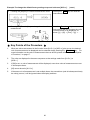
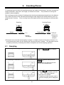
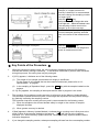
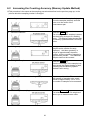


![JF日本語教育スタンダード2010 利用者ガイドブック [第二版]](http://vs1.manualzilla.com/store/data/006528957_2-434a9b0d1bd64a266fa664acf9eeb453-150x150.png)