1
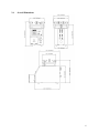
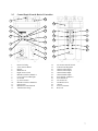
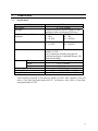
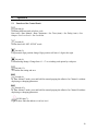
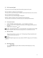
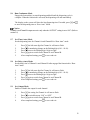
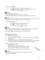
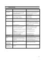
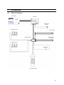
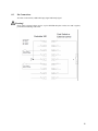
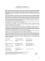
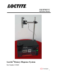
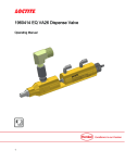
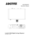
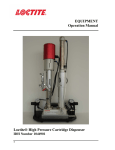
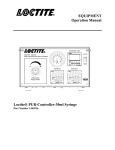
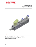
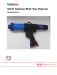
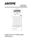
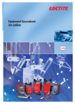
EQUIPMENT Operation Manual Loctite Integrated Semi-Automatic Dispenser Dual Channel with Low Level Sensor Part Numbers 1390322, 1390321, 0 – 1 Bar 0 – 7 Bar 1 Table of Contents 1. PLEASE OBSERVE THE FOLLOWING..................................................................................................... 3 1.1 2. DESCRIPTION ................................................................................................................................................ 3 2.1 2.3 2.4 2.5 3. SPECIFICATIONS .......................................................................................................................................... 8 INSTALLATION.............................................................................................................................................. 9 4.1 4.2 4.3 5. OPERATION.................................................................................................................................................. 3 ITEMS SUPPLIED ........................................................................................................................................... 5 OVERALL DIMENSIONS ................................................................................................................................ 6 CONTROL PANEL (FRONT & BACK OF CONTROLLER).................................................................................. 7 TECHNICAL DATA........................................................................................................................................ 8 3.1 4. EMPHASIZED SECTIONS ............................................................................................................................... 3 UNPACKING AND INSPECTION...................................................................................................................... 9 ENVIRONMENTAL AND OPERATING CONDITIONS ........................................................................................ 9 CONNECTING THE UNIT ............................................................................................................................... 9 OPERATION .................................................................................................................................................. 10 5.1 5.2 5.3 5.4 5.5 5.6 5.7 5.8 5.9 5.10 5.11 5.12 FUNCTION OF THE CONTROL PANEL:......................................................................................................... 10 XS1 CONNECTION SIGNAL: ....................................................................................................................... 11 START UP THE SYSTEM: ............................................................................................................................ 11 RUN: AUTO MODE...................................................................................................................................... 11 RUN: MANUAL MODE ................................................................................................................................ 11 RUN: CONTINUOUS MODE .......................................................................................................................... 12 SET: TIME (AUTO) MODE .......................................................................................................................... 12 SET: DELAY (AUTO) MODE ....................................................................................................................... 12 SET: OUTPUT MODE .................................................................................................................................. 12 SET: LOW LEVEL MODE ............................................................................................................................ 13 SET: LOCK-OUT MODE .............................................................................................................................. 13 ADJUST THE LEVEL SENSOR ...................................................................................................................... 13 6. TROUBLESHOOTING ................................................................................................................................. 14 7. CARE AND MAINTENANCE...................................................................................................................... 15 7.1 7.2 8. DOCUMENTATION ..................................................................................................................................... 16 8.1 8.2 9. CARE ......................................................................................................................................................... 15 MAINTENANCE .......................................................................................................................................... 15 ELECTRICAL SCHEMATIC ........................................................................................................................... 16 PIN CONNECTIONS ..................................................................................................................................... 18 ACCESSORIES, SPARE PARTS & SYSTEM COMPONENTS SOLD SEPARATELY...................... 19 2 1. Please Observe The Following 1.1 Emphasized Sections Warning! Refers to safety regulations and requires safety measures that protect the operator or other persons from injury or danger to life. Caution! Emphasizes what must be done or avoided so that the unit or other property is not damaged. Notice: Gives recommendations for better handling of the unit during operation or adjustment as well as for service activities. Warning! Never fill the product directly into the Product Reservoir! Insert only products packaged in original Loctite® containers! 2. Description 2.1 Operation The Loctite® Integrated Semi-Automatic Dispenser combines a dual channel dispense controller and reservoir into a single system. The controller provides 2 independent digital timing channels that provide control of 2 pneumatic outputs. These outputs can be used to control dispense valves, advancing slides or any other pneumatic device. The controller can be actuated either by a footswitch, finger switch or external signal. It is capable of operating in a manual or time mode for dot or bead dispensing applications. The reservoir can accommodate 50ml, 250 ml, 500 gram, 1 liter, 2 kg and 200 gram adhesive packages which deliver adhesive to dispensing valves. The system is also equipped with low level sensor which can notify the operator that the adhesive package needs to be replaced. - The Integrated Semi-Automatic Dispenser 1390322 is equipped with a precision pressure regulator 0-1 bar (0-14 PSI). The Integrated Semi-Automatic Dispenser 1390321 is equipped with a pressure regulator 07 bar (0-100 PSI). With the Integrated Semi-Automatic Dispense System, anaerobic, UV Curing and cyanoacrylate adhesive can be dispensed. The capacity of the Integrated Semi Automatic Dispenser is: - 500 gr. bottle for CA Product - 1 lb. bottle - 250 ml bottle for Anaerobics - 1 Liter bottle - Bottle with a Ø 124mm and - 2kg bottle a height of 250mm 3 2.2 Theory of Operation The Loctite® Integrated Semi-Automatic Dispenser is connected to an external pneumatic supply. It regulates the adjusted dispensing pressure and controls the dispensing during the selected dispensing time. An uncovered bottle of LOCTITE® product is placed directly into the integrated reservoir, the tube is inserted into the product, and the reservoir lid is clamped in place. It is then pressurized using clean, filtered dry air. Air within the reservoir will push down on the liquid in the bottle and force it through the product feed line to the dispensing valve. The amount of product dispensed is controlled by three main factors: – Amount of pressure in the reservoir – Length of time the dispensing valve remains open – Dispensing needle size Time Mode: 1. Press the footswitch to activate the system. 2. The dispensing timer will be activated and start to dispense with preset dispensing time. 3. After the dispensing timer has reached the preset dispensing time, the dispensing will be stopped. Manual Mode: 1. Press the footswitch to activate the system. 2. The system will start to dispense and the dispensing timer will start to count the dispensing time. 3. Once the footswitch is released, the dispensing will be stopped. Additional Features: EMPTY Signal: If the reservoir is empty the contact of the level sensor opens. Three different types of Empty Signal can be selected to indicate. Mode 1: Digital Only Mode 2: Digital + Lamp Mode 3 : Digital + System Stop READY Signal : If the dispensing cycle is finished and unit is not dispensing, a contact is closed and a <READY> signal is communicated. The ready signal only indicates that the dispensing is either on (busy) or off (ready). This signal is independent of any other system conditions. Both EMPTY and READY signals are available as dry contacts at the XS1 start interface for optional connection to an external PLC. Any external sources need to be programmed to suit end user requirements. In Mode 3, the ready signal will be communicated even though an Empty signal may be communicated, however, the system will not dispense. 4 Caution! Pay attention if cyanoacrylate is dispensed – Air in the feed line results in curing of the product! 2.3 - Items Supplied Integrated Semi-Automatic Dispenser, Dual Channel, 0-1 Bar, Order No. 1390322 or Integrated Semi-Automatic Dispenser, Dual Channel, 0-7 Bar, Order No. 1390321 Footswitch (1) Reservoir Fitting (1) Bottle Nesting Basket (1) Anti-Bubbler Fitting and Tubing Kit ¼” NPT to 6mm tube connector (1) Power Adapter with Cord (1) Operating Manual CD (1) 5 2.4 Overall Dimensions 6 2.5 Control Panel (Front & Back of Controller) 2 1 26 3 6 5 7 4 12 18 16 17 19 20 21 22 23 11 8 10 9 24 24 13 15 14 1. 2. 3. 4. 5. 6. 7. 8. 9. 10. 11. 12. 13. Reservoir Fitting Valve Pressure Relief Display Mode Switch Right Arrow Switch Manual Switch for Channel A Low Level Error LED Light Set Switch Up Arrow Switch Manual Switch for Channel B Enter Switch Main Power On/Off Switch Tank Pressure Gauge 25 14. 15. 16. 17. 18. 19. 20. 21. 22. 23. 24. 25. 26. Air Pressure On/Off Switch Tank Pressure Regulator Channel A On Output Channel A Off Output Channel B On Output Channel B Off Output XS1 Channel A (Master) XS1 Channel B Air Pressure In 24VDC Power In Silencer Low Level Sensor Reservoir 7 3. Technical Data 3.1 Specifications Attribute Time Range Air Input* Regulation Range of the Pressure Regulator Pressure Indication 0 – 1 bar (0 – 14 PSI) Power Supply: 110 – 240 V / 50 – 60 Hz Internal: 24 VDC Power Connection: Includes plug ends for North America/Japan, Continental Europe, UK, Australia and China. 7.29” (186mm) 14.26” (363mm) 13.4” (341mm) 15.4lb (7 kg) + 10°C to + 40°C (+50°F to +104°F) - 10°C to + 60°C (+14°F to +140°F) Dimensions Width Depth Height Weight Operation Temperature Storage Temperature * Value 0 – 99.99 seconds Clean, dry air not to exceed 125 psig (8.5 bar), and filtered with a maximum of 50 micron 1390322 1390321 0 – 2 bar 0 – 7 bar (0 – 28 PSI) (0 – 100 PSI) 0 – 7 bar (0 – 100 PSI) If the required air quality is not achieved, install a Loctite® filter regulator. In the US order a 5 m filter using part number 985397. In Europe or Asia, order a 10 m filter using part number 97120. 8 4. Installation 4.1 Unpacking and Inspection Carefully remove the system from its shipping carton and inspect it for any signs of damage. Any damage should be reported immediately to the carrier. Refer to the list of supplied parts (see page 4) and compare to the contents. Report any missing or damaged parts promptly. In North America contact 1-800-LOCTITE (562-8483) and for all other locations contact your local Henkel customer service. 4.2 4.3 - Environmental and Operating Conditions Keep the pressure hose as short as possible. Short switch-on and switch-off time for the dispensing valve are within reach. Keep product feed lines as short as possible. The shorter the feed line the smaller the specific resistance and the lower the dispensing pressure can be. Avoid kinking. In any case, the pressure hose and product feed line should not be longer than 2 m. Do not use inflexible hoses and feed lines, so that unnecessary loads on the fittings will be avoided. Keep all fitting tight. No direct sunlight; no UV light. No condensing humidity. No splashing water. Connecting the Unit Use only the cable and hose sets supplied. Connect power adapter with cord supplied to 24VDC power in connection (23). Connect air pressure supply to pneumatic connection (22). 9 5. 5.1 Operation Function of the Control Panel: Switch (4): Switching different mode as below cycle: Run: Auto > Run: Manual > Run: Continuous > Set: Time (Auto) > Set: Delay (Auto) > Set: Output > Set: Low Level > Set: Lock-Out Switch (8) Set the data in all “SET: XXXX” mode. Switch (5): For parameter digit position change. Digit position will move 1 digit to the right. Switch (9): For numbering change. Change from “0 – 9” or switching each option by each press. Switch (11): To confirm the setting and save. Switch (6): In “Run: Manual” mode, press and hold for manual purging the adhesive for Channel A without displaying or changing parameters. Switch (10): In “Run: Manual” mode, press and hold for manual purging the adhesive for Channel B without displaying or changing parameters. LED Light (7): Light to show when the adhesive is in low level. 10 5.2 XS1 Connection Signal: The system can be auto detecting when the footswitch(s) plug onto the system. Only XS1 Channel A (Master) Footswitch plugged: The footswitch can control both output of Channel A and Channel B and start at the same time. Only XS1 Channel B Footswitch plugged: The footswitch can only control the output of Channel B. Both XS1 Channel A (Master) and XS2 Channel B Footswitch plugged: The footswitch will control their own channel and can be started up at different times. 5.3 Start Up the System: 1. 2. Turn the “POWER” on (the position marked “ ( )” ׀12). The display (3) will turn on. If necessary, open the valve or regulator that controls the air inlet to supply pneumatic pressure to the system. Turn the “AIR” on (the position ) (14). 3. Caution: When adjusting the pressure via “Pressure Regulator”, always adjust from Low-to-High. For example, to adjust from 4 bar to 2 bar, decrease the pressure to 0~1 bar, then increase to 2 bar. 5.4 Run: Auto Mode Engage the footswitch(s) to start the cycle. The dispensing will begin immediately and continue until the system times out. Notice: Channel A and Channel B outputs are active only when the “OUTPUT” setting is set to “ON”. (Refer to section 5.8) 5.5 Run: Manual Mode Press the or parameters. to purge the adhesive manually without displaying or saving 11 5.6 Run: Continuous Mode Engage the footswitch(s) to start dispensing and hold until the dispensing cycle is complete. When the footswitch is released, the dispensing will end immediately. The display on the system will show the last dispensing time. If needed, press to store the dispensing time to “Run: Auto” Mode. and Notice: Channel A and Channel B outputs are active only when the “OUTPUT” setting is set to “ON”. (Refer to section 5.8) 5.7 Set: Time (Auto) Mode Set the dispensing time for Channel A and Channel B in “Run: Auto” mode. 1. 2. 3. 4. 5. 5.8 Set: Delay (Auto) Mode Set the delay time of Channel A and Channel B after engaged the footswitch in “Run: Auto” mode. 1. 2. 3. 4. 5. 5.9 Press , the left most digit for Channel A will start to flash. Press for numbering change on the flashing digit (0.01 – 99.99). Press to move the flashing digit 1 digit to right. again to switch from Channel A and Channel B. Press After completed setting, press to save and exit. Press , the left most digit for Channel A will start to flash. Press for numbering change on the flashing digit (0.01 – 99.99). Press to move the flashing digit 1 digit to right. Press again to switch from Channel A and Channel B. to save and exit. After completed setting, press Set: Output Mode Enable or Disable the output for each channel. 1. 2. 3. 4. Press , the setting for Channel A will start to flash. Press to switch between “ON” or “OFF”. Press again to switch from Channel A and Channel B. After completed setting, press to save and exit. 12 5.10 Set: Low Level Mode 1. Press , the setting for Low Level mode start to flash. 2. Press for switching between “OFF”, “LAMP” and “LAMP + STOP”. 3. After completed setting, press to save and exit. Notice: OFF: Only digital output from XS1 LAMP: Digital output from XS1 + LED Light on control panel LAMP + STOP: Digital output from XS1 + LED Light on control panel + System Stop Notice: The level sensor MUST be adjusted according to the type of product used, the size of the bottle, and orientation of the basket with spacers, in order to function properly. 5.11 Set: Lock-Out Mode 1. Press , the setting for Lock-Out mode start to flash. 2. Press for switch between “ON” and “OFF”. 3. After completed setting, press to save and exit. Notice: Lock-Out Mode “ON” means all setting in the system can’t be change by pressing Otherwise “Setting Locked Call Supervisor” will show on the display. Press both + to change the setting when Lock-Out Mode is “ON”. button. 5.12 Adjust the Level Sensor Before adjusting the Level Sensor 1. Empty a bottle of the product you use. 2. Leave as much residue in the bottle as is required in order to prevent air getting into the product feed line. 3. Insert the product bottle. For small bottles use the bottle nesting block. 4. Check that the product bottle inserted into the bottle nesting block is pressed against the level sensor. Only then the correct adjustment of the level sensor is possible. Procedure to Adjust the Level Sensor: 1. Turn the system power “ON”. 2. Remove the metal screw from the level sensor. 3. With an electrician’s screwdriver, find the point at which the sensor switches to the condition inactive. The LED is OFF”. 4. Check this adjustment with a full bottle and an empty bottle. Notice: The correct adjustment is exactly the point when the sensor switches “OFF”. Do not go beyond that point! 13 6. Troubleshooting Symptom The digital display does not light. No needle movement on the pressure gauge. LED does not light. No start signal. No product, too little or too much product. The desired pressure is not achieved. Air bubbles in the product. Pressurized air escapes between reservoir housing and reservoir lid. Pressurized air escapes at the product connection 1. Possible Causes Corrections Check the power voltage. Switch power switch to position I (ON). Replace power adapter with cord. Call Henkel Service. Check depressurizing valve 14 and pneumatic supply. - Pressure gauge 13 defective. Replace gauge. - Pressure regulator 15 defective. Replace regulator. - LED defect. When the controller is operational, the unit can be used until repaired by Henkel Service. - Plug on the XS1 (20 or 21) : Start 9 is Switch the power switch to the position O loose. (OFF). Tighten the screws of the plug. Switch the power switch to the position I (ON). - Footswitch defective. Replace the Footswitch. - Dispensing pressure not set correctly. Adjust dispensing pressure setting. - Pressure hose not properly connected. Connect air pressure hose correctly. - Luer-Lock tip cap not removed. Replace Luer-Lock tip cap with a dispensing needle. - Dispensing needle clogged, too small or too Replace dispensing needle. large - Dispensing valve not correctly connected Check the dispensing valve. or defective. - Product reservoir not switched on. Check product reservoir. - Product reservoir is empty. Refill product reservoir. - Supply pressure inadequate. Increase the supply pressure (min 0.5 bar above reservoir pressure). - Product reservoir is empty. Refill product reservoir. - Product hose not correctly connected. Connect product hose correctly. - Dispensing valve not correctly connected Check the dispensing valve (see instruction or defective. manual for dispensing valve). - Product reservoir pressure is too high. Lower pressure, longer dispensing time. - Reservoir knob is not tightened. Tighten the reservoir knob. - O-Ring leaky. Grease or replace the O-Ring. - No power voltage present. - Powers switch 12 in position O (OFF). - Power adaptor with cord is defective. - Control unit is defective - No air pressure present. - Union nut on the product connection not tightened. Carefully tighten the union nut. 14 7. Care and Maintenance 7.1 Care Occasionally the o-ring at the reservoir lid should be lubricated with the enclosed silicone grease. This will prolong the life of the o-ring. - Notice: Clean hands after application of grease to assure surfaces to be bonded are clean. Otherwise bonding might fail. - Clean the sensor surface as required. - Both the bottle surface and the sensor surface must be free of condensed moisture! 7.2 Maintenance - Check the reservoir knobs and the product feed line on the regular basis. If there is any sign of cracks, replace them! - Clean, dry, filtered air must be used. If it is not, the solenoids on the controller will be fouled over time. Notice: If the required air quality is not achieved, install a Loctite® filter regulator. In the US order a 5 m filter using Part Number 985397. In Europe or Asia, order a 10 m filter using Part Number 97120. 15 8. Documentation 8.1 Electrical Schematic FILM SWITCH MAIN PCB MAIN POWER SWITCH SOLENOID VALVE B START SWITCH SECONDARY PCB START SWITCH XS1 MASTER SOLENOID VALVE A POWER INPUT JACK LOW LEVEL SENSOR 16 17 8.2 Pin Connections XS1 Start via Footswitch, additional Empty Signal and Ready Signal. Warning! Never connect external voltage on pin 1 or pin 9! NEVER short pins 3 and 4, nor 6 and 7 together, permanent board damage will result. 18 9. Accessories, Spare Parts & System Components Sold Separately Loctite Item Number Description Accessories 985397 Loctite® Air Filter, Regulator, Gauge Spare Parts 8900064 Reservoir Tank Fitting, ¼ inch NPT x ¼ inch Tubing 97201 Footswitch 97972 ¼ inch O.D. Black PE Teflon Lined Fluid Feed line Tubing (33 feet length) 981880 Tank Lid O-Ring for Reservoir 992641 Pressure Safety Relief Valve 984687 Anti-Bubbler Kit, 2 Adapters & 2 Sleeves 997569 Silicone Grease, 6 Gram Tube System Components Sold Separately 97113 Stationary Dispense Valve, (1/4” Feed line) 97114 Stationary Dispense Valve, (3/8” Feed line) 98009 Light Cure Dispense Valve 98013 Cyanoacrylate Dispense Valve 97130 ErgoLoc Handheld CA Dispense Valve 1176444 Pistol Grip Trigger 19 EQUIPMENT WARRANTY For Loctite® Integrated Semi Automatic Dispenser Henkel expressly warrants that all products referred to in this Instruction Loctite® Integrated Semi Automatic Dispenser (hereafter called “Products”) shall be free from defects in materials and workmanship. Liability for Henkel shall be limited, at its option, to replacing those Products which are shown to be defective either in materials or workmanship or to credit to the purchaser the amount of the purchase price thereof (plus freight and insurance charges paid therefore by the user). The purchaser’s sole and exclusive remedy for breach of warranty shall be such replacement or credit. A claim of defect in materials or workmanship in any Products shall be allowed only when it is submitted to Henkel in writing within one month after discovery of the defect or after the time the defect should reasonably have been discovered and in any event, within twelve months after the delivery of the Products to the purchaser. No such claim shall be allowed in respect of Products which have been neglected or improperly stored, transported, handled, installed, connected, operated, used or maintained or in the event of unauthorized modification of the Products including, where products, parts or attachments for use in connection with the Products are available from Henkel, the use of products, parts or attachments which are not manufactured by Henkel. No Products shall be returned to Henkel for any reason without prior written approval from Henkel. Products shall be returned freight prepaid, in accordance with instructions from Henkel. NO WARRANTY IS EXTENDED TO ANY EQUIPMENT WHICH HAS BEEN ALTERED, MISUSED, NEGLECTED, OR DAMAGED BY ACCIDENT, OR IF THE SYSTEM USED TO DISPENSE ANY LIQUID MATERIAL OTHER THAN LOCTITE® PRODUCTS. EXCEPT FOR THE EXPRESS WARRANTY CONTAINED IN THIS SECTION, HENKEL MAKES NO WARRANTY OF ANY KIND WHATSOEVER, EXPRESS OR IMPLIED, WITH RESPECT TO THE PRODUCTS. ALL WARRANTIES OF MERCHANTABILITY, FITNESS FOR A PARTICULAR PURPOSE, AND OTHER WARRANTIES OF WHATEVER KIND (INCLUDING AGAINST PATENT OR TRADEMARK INFRINGEMENT) ARE HEREBY DISCLAIMED BY HENKEL AND WAIVED BY THE PURCHASER. THIS SECTION SETS FORTH EXCLUSIVELY ALL OF LIABILITY FOR HENKEL TO THE PURCHASER IN CONTRACT, IN TORT OR OTHERWISE IN THE EVENT OF DEFECTIVE PRODUCTS. WITHOUT LIMITATION OF THE FOREGOING, TO THE FULLEST EXTENT POSSIBLE UNDER APPLICABLE LAWS, HENKEL EXPRESSLY DISCLAIMS ANY LIABILITY WHATSOEVER FOR ANY DAMAGES INCURRED DIRECTLY OR INDIRECTLY IN CONNECTION WITH THE SALE OR USE OF, OR OTHERWISE IN CONNECTION WITH, THE PRODUCTS, INCLUDING, WITHOUT LIMITATION, LOSS OF PROFITS AND SPECIAL, INDIRECT OR CONSEQUENTIAL DAMAGES, WHETHER CAUSED BY NEGLIGENCE FROM HENKEL OR OTHERWISE. Henkel Corporation One Henkel Way Rocky Hill, CT 06067-3910 USA Henkel Canada Corporation 2515 Meadowpine Boulevard Mississauga, Ontario L5N 6C3 Canada Henkel Corporation Automotive/ Metals H.Q. 32100 Stephenson Hwy, Madison Heights 48071 USA Henkel Capital, S.A. de C.V. Calzada de la Viga s/n Fracc. Los Laureles Loc. Tulpetlac, C.P. 55090 Ecatepac de Morelos, MEXICO Henkel Singapore Pte Ltd Blk 5002 Ang Mo Kio Ave 5 #03-12 TECHplace 2, 569871 SINGAPORE Henkel (China) Company Ltd. No. 928 Zhang Heng Road, Zhangjiang, Hi-Tech Park, Pudong, Shanghai, China 201203 Henkel Loctite Korea 8F, Mapo Tower, 418, Mapo-dong, Mapo-gu, Seoul, 121-734, KOREA Henkel Japan Ltd. 27-7 Shin Isogo-cho, Isogo-ku Yokohama, 235-0017 JAPAN www.equipment.loctite.com Loctite is a trademark of Henkel Corporation, U.S.A. © Copyright 2006. Henkel Corporation Teflon is a registered trademark of E.I. DuPont de Nemours Co., Inc. All rights reserved. Data in this operation manual is subject to change without notice. Manual P/N: 8902415, Rev C, Date: 12/02/2013 20