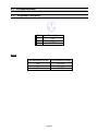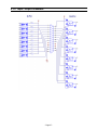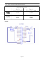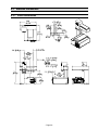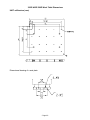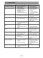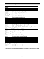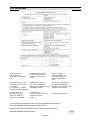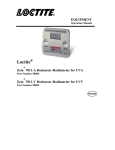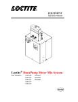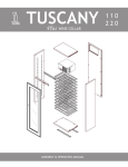
1
BENCHTOP 24V D-ROBOTS OPERATION MANUAL Table of Contents SECTION 1: 1.1 1.2 1.3 1.4 INTRODUCTION ...................................................................................................... 4 SAFETY PRECAUTIONS........................................................................................... 4 PACKAGE CONTENTS............................................................................................. 5 CONNECTOR AND SWITCH LOCATIONS .................................................................... 6 SECTION 2: 2.1 2.2 3.1 3.2 3.3 EQUIPMENT OPERATION ....................................................................13 USING THE TEACH PENDANT .................................................................................. 14 CHANGING THE PROGRAM NUMBER ........................................................................ 17 CHANGING FROM TEACH MODE TO RUN MODE ........................................................ 17 SECTION 4: 4.1 4.2 4.3 4.4 4.5 4.6 4.7 4.8 BASIC ERROR MESSAGES AND RESOLUTION ................................18 Point Closed Error ..............................................................................................................................19 Need Line Start Point...........................................................................................................................19 Need Step & Repeat .............................................................................................................................19 Unlock Program ..................................................................................................................................19 Address Over Memory .........................................................................................................................20 Move Over Memory .............................................................................................................................20 System Error ........................................................................................................................................20 Over Speed Error.................................................................................................................................20 SECTION 5: SPECIFICATIONS..................................................................................21 I/O SPECIFICATIONS .............................................................................................. 22 SYSTEM SPECIFICATIONS ....................................................................................... 29 MACHINE DIMENSIONS ........................................................................................... 30 SECTION 6: 6.1 6.2 MACHINE SETUP ..................................................................................11 UNPACKING THE ROBOT ........................................................................................ 12 SETUP .................................................................................................................. 12 SECTION 3: 5.1 5.2 5.3 INTRODUCTION ....................................................................................3 MAINTENANCE, ACCESSORIES & SPARE PART..............................36 MAINTENANCE ...................................................................................................... 37 ACCESSORIES & SPARE PARTS .............................................................................. 39 SECTION 7: EQUIPMENT WARRANTY.....................................................................40 7.1 EQUIPMENT WARRANTY ......................................................................................... 41 SECTION 8: EC DECLARATION .................................................................................... 42 - Page 2 - SECTION 1: Introduction - Page 3 - 1.1 Introduction Welcome to the Henkel Benchtop Robots operation manual, this manual is an instructional guide designed for system operators, technicians and engineers. It provides a complete tour for how to operate the Henkel Benchtop Robot. Please check the Henkel Benchtop Robot software manual 8902886 if you need instructions for how to program. 1.2 Safety Precautions In order to meet the requirements of the European Community (CE) safety directives, the robot must be placed in an enclosure1 supplied by Henkel. 1.1 Make sure the robot is connected to a properly grounded power source before operating. 1.2 Keep away from any moving parts while the robot is running. 1.3 Loading and unloading of parts and material must only be done when the robot is at a complete stop. 1.4 Changing of fixtures or tooling must be done with the power source disconnected. 1.5 The robots should only be operated in an environment between 0 and 40 degrees Celsius with humidity of 20 to 95 percent and no visible condensation. 1.6 Do not store or setup the robot in an area where it is directly exposed to sunlight. 1.7 Do not operate the robot where electrical noise is present. 1.8 Only use a neutral chemical for cleaning the robot. Do not use alcohol, benzene or thinner as it may damage the paint on the robot. 1 The light curtain enclosure or safety door enclosure will prevent the operator from entering the robot’s work area and will generate an emergency stop signal if the light curtain is interrupted or the enclosure’s door switch is opened while the robot is running. - Page 4 - 1.3 Package Contents In addition to this operating manual, the following items should be included with the robot: 1. 2. 3. 4. 5. 6. 7. Main Unit (200D/300D/400D/500D) Syringe Holder, 30-55ml, Fixed External Control Shorted Connector Dispensing Cable Mounting Screw for Syringe Holder Power Cord USB memory stick - Page 5 - 1.4 Connector and Switch Locations 1.4.1 200D Front View START PROG NO. RUN TEACH Rear View RoHS Compliant Warning: FOR SPARE PARTS, MANUALS, REPAIRS, OR TECHNICAL ASSISTANCE: Visit us at equipment.loctite.com or call Henkel Corp. at: USA - (1) 860-571-5174 Germany - (49) 89-9268-0 Singapore - (65) 6482-3881 Disconnect Power Cord Before Servicing Voltage: 120-240V/50-60Hz 0.5~1 Amps Ext.Control Label P/N: 988341 Power Switch Henkel Corporation Dispenser Loctite? 200D Benchtop Robot Item No. 1328352 Serial No. 9ETAA-001 I / O PORT Made in Taiwan R.O.C. - Page 6 - Power Inlet NCY GE Teach Pendant OP ST PURGE EMER 200D Benchtop Robot 1.4.2 300D Front View Rear view - Page 7 - 1.4.3 400D Front View Rear View - Page 8 - 1.4.4 500D Front View Rear View - Page 9 - SECTION 2: Machine Setup - Page 11 - 2.1 Unpacking the Robot Always lift the robot from its base. Never lift the robot from the cross member. Remove all accessories from the shipping package before attempting to remove the robot. Place the robot on a stable workbench before operating. If you can, do not discard the packing material as these items may be needed if the robot is shipped or moved in the future. 2.2 Setup The robots are available with different configurations. The setup of each machine with its accessories will depend on the customer’s application. 1. Connect the external start / stop box and door switch or light curtain to the External Control connector on the main unit. For further information, see SECTION 5.1.2: External Control Connector. If an enclosure is NOT being used, the enclosure door switch may be bypassed by connecting the plug labeled SHORTED (included in the robot accessories box) to the External Control Connector. 2. 3. 4. 5. Remove the shipping bracket 2 by removing the screws that secure it. Keep the shipping bracket and screws in a safe place for future use. Connect one end of the Teach Pendant cable to the Teach Pendant and the other end to the Teach Pendant connection on the robot. Connect the power cord of the robot to the power socket on the robot. Be sure to use the correct power cord and power source for the robot model you are using (110 V or 220 V). Tie back all cables and air lines so that they will not interfere with the robot’s motion when the robot is operating. Be sure that the cables and air lines do not restrict the motion of the robot’s head and the robot’s table and make sure that they can not become jammed as the robot moves through the work area. 2 The robots are shipped from the factory with a shipping bracket installed. The shipping bracket secures the worktable to the X/Z head to prevent movement and damage during shipment. - Page 12 - SECTION 3: Equipment Operation - Page 13 - 3.1 Using the Teach Pendant The teach pendant enables the user to jog the robot to input program data. 3.1.1 Key Selection There are several functions assigned to most keys on the Teach pendant. When a key is pressed alone, the function shown in the dark grey colored area on the key is executed. For example, Ins, Del, Jump, Clear and Esc are the default key functions, which are executed when that key is pressed alone. To access the function shown in the light grey area at the top of a key, press and release the Shift key first (the LED on the Shift key will be flashing), then press the desired key. For example, to select the Speed function, press and release Shift, then press the Speed key. When a number is required, the teach pendant will automatically switch to numeric entry mode. The number represented by each key is shown in the lower right corner of the key. - Page 14 - 3.1.2 Key Assignments Menu Keys Opens the Point registration menu Select the options shown on the display Opens F2 Menu Select the options shown on the display Opens F3 Menu Select the options shown on the display Opens the F4 Setup menu Select the options shown on the display Jog Keys Jogs the X-axis in the left direction. Jogs the X-axis in the right direction. Jogs the Y-axis in the backward direction. Jogs the Y-axis in the forward direction. Jogs the Z-axis UP. Jogs the Z-axis DOWN. Accelerates jog speed – used with X+, X-. Y+, Y-, Z Up, Z Down Navigation Display Moves forward (1) memory address. Moves backward (1) memory address. - Page 15 - 3.1.3 Navigation Menu Once the menu is open, use the up and down arrows to move through the items on the menu. Use left and right arrows to change to the next page or previous page of the menu. Press ENTER to select the current item. 3.1.4 Jogging The tip is jogged by pressing the jog buttons If the FAST button is pressed and held first, then one of the jog buttons is pressed, the axis will be jogged at the maximum jog speed. If one of the jog buttons is pressed first, then the FAST button is pressed, the jog motion will accelerate. If the FAST button is released, the jog motion will decelerate. 3.1.5 Data Entry If a numeric value is required, the teach pendant will automatically switch to numeric mode. Use the keys 0 – 9, (.) and the minus sign (-) to enter numbers. 3.1.6 Running a Program Press the key to run the program. - Page 16 - 3.2 Changing the Program Number The program number is selected by the program number selection switches on the main unit’s control panel. Press the + and – buttons to select the program number. Note: Program 99 is designed for “autorun” on Run mode. When starting the robot with this program, the robot starts automatically without pressing the Start/Home key for initialization. 3.3 Changing from Teach Mode to Run Mode To change from Teach mode to Run mode, change the position of the mode switch on the main unit’s control panel. When the machine is in Run mode, the teaching box (teach pendant) is not required. Programs can be selected and run using the switches on the front control panel of the main unit. To get detail information for how to programming and more help for the software, please read Henkel DRobot Software Manual 8902886. - Page 17 - SECTION 4: Basic Error Messages and Resolution - Page 18 - 4.1 Point Closed Error This message occurs when two adjacent line or arc points are registered at exactly the same XYZ location. Resolution: 4.2 Do not register two line points one after the other at exactly the same XYZ location. Need Line Start Point An attempt was made to register a Line Passing point, an Arc point or a Line End point without first registering a Line Start point. Resolution: 4.3 Register a Line Start point before registering a Line Passing point, Arc point or a Line End point. Need Step & Repeat The Expand Step & Repeat command was given but there is no Step & Repeat instruction currently in the display. Resolution: 4.4 Select the Step & Repeat function you want to expand before selecting Expand Step & Repeat. Unlock Program An attempt was made to edit a program in Teach mode, which is locked. The program cannot be edited until it is unlocked. Resolution: Unlock the program in F2 Menu Utility Menu Lock Program. - Page 19 - 4.5 Address Over Memory An attempt was made to copy data but the copy would exceed the maximum memory address. Resolution: 4.6 Reduce the data to be copied. Move Over Memory An attempt was made to move data but the move would exceed the maximum memory address. Resolution: 4.7 Reduce the data to be moved. System Error This message indicates a problem with the Main PC Control Board. Resolution: 4.8 Please contact your dealer. Over Speed Error This message indicates the setting speed of the address showed on the screen are over the maximum allow speed for the robot. This error may caused by high speed running for very short path, shaft corner or small arc/circle. Note: When an error occurs, it will be displayed on the Teach Pendant. If the Teach Pendant is not connected to the robot, you will first have to turn off the robot, then connect the Teach Pendant to the robot for it to properly function. - Page 20 - SECTION 5: Specifications - Page 21 - 5.1 I/O Specifications 5.1.1 Dispenser Connector: Pin # 1 2 3 Description NO COM EARTH Notes: The MAXIMUM Current 12A 7A 7A The MAXIMUM Voltage 125 VAC 250 VAC 30 VDC - Page 22 - 5.1.2 Ext. Control Connector: The pin assignments for the external control connector are as follows: Pin # 1 2 3 4 5 6 7 Description Start Signal Start Signal Door Switch (COM) Door Switch (NC) Door Switch (NO) Emergency Stop Emergency Stop - Page 23 - 5.1.3 Output Signals Pin # 14 15 16 17 18 19 20 21 22 23 24 25 Output Type: Description DISP START OUT OUT #2 OUT #3 OUT #4 OUT #5 OUT #6 OUT #7 OUT #8 RESERVE RESERVE +24V +24V Photo-coupler Output Power: - Output signals are able to provide a maximum of 24 volts. - Output signals are able to provide a maximum of 250 milliamps per pin. Function: - When the output signal is closed, the circuit between the output pin (pin #14 #21) and the +24 Volt power supply (pin # 24 - #25) is closed. - The output pin (pin #14 - #21) is connected to the power supply GROUND. - Pins #24 - #25 are all the same. They are all connected to the +24 volt power supply. - Page 24 - IMPORTANT NOTES: 1. Output signals should be used only to drive external relays. Do not power external devices directly through output signals. Electrical noise will damage the output signal relay. 2. If an inductive load (such as a relay) is connected to an output signal, be sure to install a diode as shown to prevent damage to the output photocoupler: - Page 25 - 5.1.4 Input Signals Pin # 1 2 3 4 5 6 7 8 9 10 11 12 13 Description IN # 1 IN # 2 IN # 3 DISP READY IN + IN # 5 IN # 6 LOW LEV IN + IN # 8 RESERVE RESERVE COM GND COM GND COM GND Notes: 1. To close an input signal, short the circuit between the input pin (1 – 8) and a GND / ground pin (any pin # 11 - pin 13). 2. Input signals are powered by the robot internal power supply: 24 volts, maximum 50 mA. 3. Check the status of an input signal using the SET I/O command (see Error! Reference source not found. - Error! Reference source not found.). When the input pin (pin 1 – 8) is connected to a GND pin (pin #11 - #13), the value of the input is 0. - Page 26 - 5.1.5 Input / Output Schematic - Page 27 - 5.1.6 Input / Output Power Specifications 200D/300D/400D/500D Inputs (Internal Power Supply) Outputs (Internal Power Supply) MAXIMUM Voltage 24 VDC 24 VDC MAXIMUM Current 50 mA 250 mA Example: - Page 28 - 5.2 System Specifications 200D 300D 400D 500D Working Area X / Y / Z (mm) 200 /200 / 50 300 / 300 / 100 400 / 400 / 100 500 / 500 / 100 Load Worktable / Tool 3.0kg / 2.0kg 10.0kg / 5.0kg 400 / 200 600 / 320 +/- 0.04mm/Axis +/- 0.01mm/ Axis 0.02mm/Axis 0.001mm/Axis Maximum Speed X&Y / Z (mm/sec) Repeatability Resolution 4000 points/program 100 programs Data Memory capacity 32 Bit Processor Teach Pendant LCD Display Drive System /Stepping Motor Micro stepping 3-Phase Motion Control PTP & CP Linear / Circular Interpolation 3 axes Teaching Method Teach Pendant 8 Inputs / 8 Outputs I/O Signals RS232 External Interface Auto-switching: AC95-132V 240W AC180-250V 240W Power Supply Working Temperature 0 – 40 C Relative Humidity (no condensation) 20 – 90% Dimensions (WxDxH) (mm) Weight 350 x 330 x 490 485 x 500 x 600 585 x 600 x 600 685 x 701x 600 18 kg 32 kg 40 kg 45 kg - Page 29 - 5.3 Machine Dimensions 5.3.1 200D Dimensions 200D Benchtop Robot Label P / N: 988341 Henkel AG & Co. KGaA Standort München Gutenbergstr. 3 D-85748 Garching Loctite ® 200D 24V Benchtop Robot Item No. 1597107 Serial No. 09GTAA-XXX Year of Manufacture: - Page 30 - 5.3.2 300D Dimensions UNIT: millimeters (mm) A 300D Benchtop Robot A - Page 31 - 5.3.3 400D Dimensions UNIT: millimeters (mm) - Page 32 - 5.3.4 500D Dimensions UNIT: millimeters (mm) - Page 33 - 5.3.5 Work Table Dimensions 200D Work Table Dimensions UNIT: millimeters (mm) Dimensional drawing of z-axis plate - Page 34 - 300D/ 400D/ 500D Work Table Dimensions UNIT: millimeters (mm) Dimensional drawing of z-axis plate - Page 35 - SECTION 6: Maintenance, Accessories & Spare Part - Page 36 - 6.1 Maintenance 6.1.1 General Consideration It is essential to correctly and periodically inspect and maintain the robot to prevent unexpected failures or malfunctions, thus ensuring safe operation and lengthening the machine’s life. The outside parts of the machine should be kept clean. Use vacuum cleaner or soft cloth to clean the machine. Do not use compressed air or chemical products to clean the machine, as they can damage the internal cables, timing belts and other components of the unit. Use only the greasing materials recommended by the manufacturer of the machine. 6.1.2 Check Cycles and Points The check cycles of the machine are classified in the following categories: Daily check Weekly check Check after every 3 months of operation Check after every 3 years of operation The checkpoints are as follows: CHECK CYCLE CHECK POINT Daily Tilt or deviation of machine Status of cables and hoses Appearance Stability on the work bench Motor running condition Motions, connections and joints Unfastened / loose bolts and screws Internal wires and connectors Accuracy and precision Ball screw assembly, LM guide, slide guide Overhaul Weekly Every 3 months Every 3 years X X X X - Page 37 - X X X X X X X 6.1.3 Check Methods Check point Check action (See if) Corrective action Tilt or deviation of machine Status of cables and hoses Robot working position is tilted or inclined Electrical cables and pneumatic hoses are excessively twisted, bent, or squeezed Air leakage between pneumatic hoses and fittings Appearance Damage on the robot’s head from clashes during operation Stability on work bench The robot is too close to the edge of the work table Motor running condition Motions, connections, and joints Infiltration of grease Performance degradation due to overload The axes are not moving smoothly Noises, vibrations, and / or shakes Loose or broken bolts and nuts Unfastened / loose bolts and screws Internal wires and connectors Accuracy and precision Ball screw (worm) assembly, LM guide, slide guide Overhaul Stripped or damaged external cover or shield on cable and/or connectors Z run out over X or Y larger than 0.2mm Wear on timing belt Lack of grease on shaft, LM guide and / or slide guide surfaces Deflection of the shaft Diagnose the whole system and make decision for the overhaul - Page 38 - Set the machine in a proper vertical position Remove the causes of twisting, bending, or squeezing Cut away the damaged parts of hoses and make connections Pay attention to working area of robot and remove any obstacle Rearrange the position of the robot on the table Remove sources causing table vibration Replace motor (see agent) Grease up Reset and adjust gains (contact agent for setting) Tighten loose bolts and nuts. Take corrective action to remove the cause Replace the damaged cables or connectors with new ones (see agent) Contact agent Replace timing belt (see agent) Apply grease on greasehole of worm, LM guide, and slide guide surfaces (see section 9:2) Replace the shaft (contact agent) Contact agent 6.2 Accessories & Spare Parts Loctite Item Description Number Accessories 1328355 Teach Pendant, D Series Robot 1329222 Interface Cable, D Series Robot 1461974 I-O Junction Box, D Series Robot 24V 988000 Solenoid Valve Module, 24V, D Series Robot 1569523 Needle Calibration Kit Mounting Bracket 1328355 Syringe Holder, 30-55ml, Fixed 98316 30ml Syringe Mounting Bracket Kit 98318 300ml Cartridge Mounting Bracket Kit 98326 98009 and 98013 Valve Mounting Bracket Kit 98327 97113 and 97114 Valve Mounting Bracket Kit 98406 983914 and 986300 Poppet Valve Mounting Bracket Kit 98441 98520 Spray and 98084 Micro Needle Valve Mounting Bracket Kit 98646 Universal Syringe Bracket for Posi-LinkTM 98647 50ml Dual Cartridge Bracket for Posi-LinkTM 98669 98591 and 98595 LED Mounting Bracket Kit 1034030 98601, 98665, 976418 and 976420 LED Mounting Bracket Kit 3, 5 and 10ml Syringe Adapters 98320 10ml Adapter for Use with 98316 98321 5ml Adapter for Use with 98316 98322 3ml Adapter for Use with 98316 360 Degree Rotation Kit 98325 360 Degree Rotation Kit Tip Locator Brackets* 98332 Tip Locator Bracket for 30ml Syringes 98333 Tip Locator Bracket for 300ml Cartridge 98334 Tip Locator Bracket for 98009 and 98013 Valves 98335 Tip Locator Bracket for 97113 and 97114 Valves 98407 Tip Locator Bracket for 983914 and 986300 Poppet Valve Z Height Adjustment Plate 98357 Z Height Adjustment Plate 929541 Z Height Adjustment Plate – Posi-LinkTM 200 – 400 Nests Mounting Rails 98328 3¾ Inch Bar with Two Cap Screws 98329 8¾ Inch Bar with Two Cap Screws * These are sized for 25 gauge needles and must be modified by the user for larger gauge sizes. - Page 39 - SECTION 7: Equipment Warranty - Page 40 - 7.1 Equipment Warranty For Loctite® D-Series Benchtop Robot ® Henkel expressly warrants that all products referred to in this Instruction Loctite D-Series Benchtop Robots (hereafter called “Products”) shall be free from defects in materials and workmanship. Liability for Henkel shall be limited, at its option, to replacing those Products which are shown to be defective either in materials or workmanship or to credit to the purchaser the amount of the purchase price thereof (plus freight and insurance charges paid therefore by the user). The purchaser’s sole and exclusive remedy for breach of warranty shall be such replacement or credit. A claim of defect in materials or workmanship in any Products shall be allowed only when it is submitted to Henkel in writing within one month after discovery of the defect or after the time the defect should reasonably have been discovered and in any event, within twelve months after the delivery of the Products to the purchaser. No such claim shall be allowed in respect of Products which have been neglected or improperly stored, transported, handled, installed, connected, operated, used or maintained or in the event of unauthorized modification of the Products including, where products, parts or attachments for use in connection with the Products are available from Henkel, the use of products, parts or attachments which are not manufactured by Henkel. No Products shall be returned to Henkel for any reason without prior written approval from Henkel. Products shall be returned freight prepaid, in accordance with instructions from Henkel. NO WARRANTY IS EXTENDED TO ANY EQUIPMENT WHICH HAS BEEN ALTERED, MISUSED, NEGLECTED, OR DAMAGED BY ACCIDENT. EXCEPT FOR THE EXPRESS WARRANTY CONTAINED IN THIS SECTION, HENKEL MAKES NO WARRANTY OF ANY KIND WHATSOEVER, EXPRESS OR IMPLIED, WITH RESPECT TO THE PRODUCTS. ALL WARRANTIES OF MERCHANTABILITY, FITNESS FOR A PARTICULAR PURPOSE, AND OTHER WARRANTIES OF WHATEVER KIND (INCLUDING AGAINST PATENT OR TRADEMARK INFRINGEMENT) ARE HEREBY DISCLAIMED BY HENKEL AND WAIVED BY THE PURCHASER. THIS SECTION SETS FORTH EXCLUSIVELY ALL OF LIABILITY FOR HENKEL TO THE PURCHASER IN CONTRACT, IN TORT OR OTHERWISE IN THE EVENT OF DEFECTIVE PRODUCTS. WITHOUT LIMITATION OF THE FOREGOING, TO THE FULLEST EXTENT POSSIBLE UNDER APPLICABLE LAWS, HENKEL EXPRESSLY DISCLAIMS ANY LIABILITY WHATSOEVER FOR ANY DAMAGES INCURRED DIRECTLY OR INDIRECTLY IN CONNECTION WITH THE SALE OR USE OF, OR OTHERWISE IN CONNECTION WITH, THE PRODUCTS, INCLUDING, WITHOUT LIMITATION, LOSS OF PROFITS AND SPECIAL, INDIRECT OR CONSEQUENTIAL DAMAGES, WHETHER CAUSED BY NEGLIGENCE FROM HENKEL OR OTHERWISE. - Page 41 - 8 EC Declaration Henkel Corporation One Henkel Way Rocky Hill, CT 06067-3910 USA Henkel Canada Corporation 2515 Meadowpine Boulevard Mississauga, Ontario L5N 6C3 Canada Henkel Corporation Automotive/ Metals H.Q. 32100 Stephenson Hwy, Madison Heights 48071 USA Henkel Capital, S.A. de C.V. Calzada de la Viga s/n Fracc. Los Laureles Loc. Tulpetlac, C.P. 55090 Ecatepac de Morelos, MEXICO Henkel Singapore Pte Ltd 401, Commonwealth Drive #03-01/02 Haw Par Technocentre SINGAPORE 149598 Henkel (China) Company Ltd. No. 928 Zhang Heng Road, Zhangjiang, Hi-Tech Park, Pudong, Shanghai, China 201203 Henkel Loctite Korea 8F, Mapo Tower, 418, Mapo-dong, Mapo-gu, Seoul, 121-734, KOREA Henkel Japan Ltd. 27-7 Shin Isogo-cho, Isogo-ku Yokohama, 235-0017 JAPAN www.equipment.loctite.com Loctite is a trademark of Henkel Corporation, U.S.A. © Copyright 2006. Henkel Corporation Teflon is a registered trademark of E.I. DuPont de Nemours Co., Inc. All rights reserved. Data in this operation manual is subject to change without notice. Manual P/N: 8902566 Rev D, Date: 03/27/2014 - Page 42 -