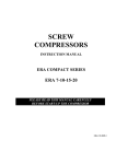
1
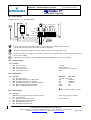
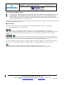
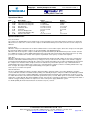
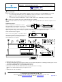
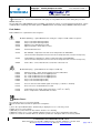
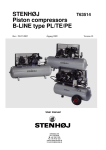
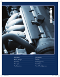
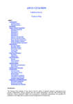
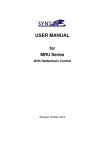
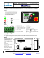
Part No.: Copyright 746110 Stenhøj Compressor 2009 T91003 User manual version: 1 TM Stenhøj Silence Pack 2009 The AirMaster P1 has been custom designed and engineered as a cost efficient control solution for Stenhøj Silence Pack type K11/K112/K13 as 10 and 15bars versions. Interface: • • • 6 tactile feedback push button type keys integrated in to the front overlay design. Industrial push button Emergency Stop Self locking; twist to unlock. 95 element custom backlit LCD Keys: Start Up or Increment Value Stop Down or Decrement Value Reset Enter Display: 1 2 5 1: 2: 3: 4: Main Display Value Main Display Value Units User Menu Item Display Value User Menu Item Display Units 0.1 to 999 o o BAR, PSI, C, F 0.1 to 99999 o o BAR, PSI, C, F, Hr, LHr 5: Status Symbols Started, Running, Loaded 6 Service, 6: Service/Fault Symbols 3 Fault: Alarm/Warning/Trip 4 Construction: Cast Aluminum alloy housing, process black corrosion protective coating and corrosion protected steel rear plate. IP65 keypad overlay and panel mount sealing. Mounting: 144 Front panel mounting (1.0mm to 2.5mm plate thickness) with 4 x M4 clearance holes for front accessible screw, self-tap, nut/bolt or rivet type fixings. A2 A1 - - + + C6 28 10 C2 Connections: 2 2 0.5mm to 1.5mm CSA wire screw terminals. 96 Emergency Stop – 2 x 110’ push fit ‘faston’ connectors Earth Tabs – 2 x 250’ push fit ‘faston’ connectors R1 4 x M4 clearance 24Vac 0V R1C R2 R3 R4 C STENHØJ KOMPRESSOR A/S Barrit Langgade 188-190, DK-7150 Barrit, Tlf.: +45 7682 1260, Fax: +45 7682 1226 E-mail: [email protected], Webside: www.stenhoj.dk page 1 of 7 Part No.: Copyright 746110 Stenhøj Compressor 2009 T91003 User manual version: 1 TM Stenhøj Silence Pack 2009 X01 – Power Supply: Controller: 24Vac +-15%; 50VA @ 50/60Hz R1C R1 C R2 R3 R4 Di ES 0Vac 24Vac 24Vac 0Vac It is recommended the 0Vac power supply is securely bonded to a suitable earth connection. Polarity of power supply connection to the controller is important. Emergency Stop (ES) activation is detected on R1C (relay #1 common pin); 24Vac only. If common 24Vac power supply is used for motor contactor coil energisation the ‘VA’ power supply rating must be increased accordingly. Di Main 24Vac power supply is used for digital input activation (digital inputs are 24Vac detecting). X02 – Analogue Inputs: Pin Function 1 2 3 4 A1+ A1A2+ A2- Pressure Sensor Pressure Sensor Temperature Sensor Temperature Sensor + 16VDC 4-20mA Signal KTY (NTC 10k, PT100, PT1000) 0VDC X03 – Digital Inputs: Pin Function 1 2 3 4 5 C1 C2 C3 C4 C5 C6 ON: 24Vac Emergency Stop Shutdown Trip Fault (e.g. Motor Fault) Shutdown Trip Fault (e.g. Oil Filter) Shutdown Trip Fault (e.g. Separator Element) Menu Configurable (Default: Alarm) Menu Configurable (Default: Alarm) OFF: 0Vac see Relay Outputs R1C OK OK OK Alarm Alarm Shutdown Shutdown Shutdown OK OK ON= > 19.8Vac, OFF = < 1.0Vac X04 – Relay Outputs: Pin Function 1 2 3 4 5 6 R1C R1 C R2 R3 R4 Emergency Stop Detection; Relay #1 Common Load Solenoid Relay #2, #3 and #4 Common Main/Line Motor Contactor Coil Start Motor Contactor Coil Delta Motor Contactor Coil 24Vac only (<1.0Vac = E.Stop) max. 130Vac/dc STENHØJ KOMPRESSOR A/S Barrit Langgade 188-190, DK-7150 Barrit, Tlf.: +45 7682 1260, Fax: +45 7682 1226 E-mail: [email protected], Webside: www.stenhoj.dk page 2 of 7 Part No.: Copyright 746110 Stenhøj Compressor 2009 T91003 User manual version: 1 TM Stenhøj Silence Pack 2009 User Display: Main Display Value; Pressure (bar/psi menu selectable) o o Default User Menu Item; Temperature ( C/ F menu selectable) To view alternative User Menu items press Up or Down Total Run Hours Hours Run Onload Hours Until Service Due (countdown timer based on total run hours) RS485 Communication Network Address (*only show if RS485 option installed) If a timer event occurs (run-on, stop, blowdown or auto restart time) the User item display will show the time countdown in seconds. While a countdown is being displayed normal User items can still be viewed; press Down. The display will default back to the User Temperature item after a short period of no key activity or after a timer event has completed. If operating in ‘Pressure Switch Mode’ the main display will show the detected temperature and the default User Menu item will be total run hours. Pressure is not displayed in pressure switch mode. Pressure Switch Mode Status Display: The operating status is continuously displayed using status symbols. Standby: The compressor is in a started state but is not running. The compressor will automatically re-start and load when pressure falls to the lower pressure set point; or a remote load signal. Running: The compressor is running offload (run-on-time active) Loaded: The compressor is running onload Fault Conditions: If a Fault condition occurs the Fault triangle symbol will switch on steady (Alarm/Warning) or flash (Trip/Shutdown) The User menu display item will show a ‘Fault Code’ dependant on the fault. Fault Codes STENHØJ KOMPRESSOR A/S Barrit Langgade 188-190, DK-7150 Barrit, Tlf.: +45 7682 1260, Fax: +45 7682 1226 E-mail: [email protected], Webside: www.stenhoj.dk page 3 of 7 Part No.: Copyright 746110 Stenhøj Compressor 2009 T91003 User manual version: 1 TM Stenhøj Silence Pack 2009 Service Due Countdown Timer: If the Service Due countdown timer reaches 0(zero) hours the Service and Alarm symbols will flash and the service Alarm (Warning) code will be displayed. The alarm code can be reset but the service symbol will remain on the display until the service due timer is reset; the service hours will continue to decrement in negative hours. The service countdown timer can be reset, using the menu routine, when the required service has been carried out. Set to any value greater than 0(zero) hours before reset. The Service Due countdown timer can be reset to any hours value, dependant on the required service interval. The timer will countdown dependant on total run hours. Menu Routine: Parameters, Values and Options can be adjusted and set using the Menu Routines. There are two menu lists: 1) Operational Menu – Access Code “0009” To access a menu stop the compressor first then press the Up and Down buttons simultainiously. After several seconds the display will show four “0” characters; the first character will flash. Press Up or Down to adjust the first character to match the first character of the required access code. Press Enter to increment to the second code character. When all four access code characters have been set, and the last code character is flashing, press Enter. If the access code is correct for access to one of the two menus the first menu item of the appropriate menu will be displayed. If the access code is incorrect the display will return to the normal operational display. To select a menu item for adustement press Up or Down until the menu item is displayed. To adjust an item setting press Enter, the value or option will flash. Press Up or Down to adjust as required then press Enter to store in memory. To exit a menu and return to the normal operational display, at any time, press Reset. Any adjustement that has not be entered to memory will be abandoned and the previous setting maintained. STENHØJ KOMPRESSOR A/S Barrit Langgade 188-190, DK-7150 Barrit, Tlf.: +45 7682 1260, Fax: +45 7682 1226 E-mail: [email protected], Webside: www.stenhoj.dk page 4 of 7 Part No.: Copyright 746110 Stenhøj Compressor 2009 T91003 User manual version: 1 TM Stenhøj Silence Pack 2009 Operational Menu: Item 1: 2: 3: 4: 5: 6: 7: 8: 9: 1.Sh 1.Pu 1.PL 1.rt 1.bt 1.St 1.P1.t1.At Description Service Interval Hours Upper Pressure Set point Lower Pressure Set point Run-On-Time Blowdown Time Stop Time Pressure Display Units Temperature Display Units Auto Resetart Time Range -999 to 9999 hours 1 to 68bar 0.8 to 67.8bar 0 to 600 seconds 0 to 120 seconds 0 to 30 seconds bar/psi o o C/ F 0 to 120 seconds Default 2000 hours 10.0bar 8.0 bar 10 seconds 0 seconds 0 seconds bar o C 10 seconds Operational Menu Items: Pressure Control: The compressor will maintain pressure between the set Pu (Unload Pressure Set Point) and PL (Load Pressure Set Point. When Pressure reaches the set ‘Pu’ level the compressor will unload. When pressure falls to the ‘PL’ level the compressor will load. Run-On-Time: When the compressor unloads the run-on-timer is initiated. If the set run-on-time expires before the compressor loads again the main motor will stop and the compressor enter the Standby state.Blowdown Timer: When the main motor stops the compressor will allow a period of blowdown (the Blowdown Time) before a motor start can be re-initiated. A motor re-start is inhibited during this time period. This time is intended to allow internal pressure (or sump pressure) to be vented before a motor start sequence is permitted. Set to 0(zero) seconds if not required. Stop Time: When the Stop button is pressed the compressor will unload and the main motor will continue to run for the set Stop Time. This time is intended to allow internal pressure (or sump pressure) to reduce before the compression element is stopped; preventing potential oil blow-back through the compression element and air filter. The stop time is initiated from the moment the compressor is unloaded. If the compressor has been offload for a period of time prior to a stop command the time is automatically reduced accordingly. If the compressor is stopded after the compressor has been running offload for the stop time, or longer, the compressor is stopped immediately; no stop time is applied. Set to 0(zero) seconds if not required. Auto Restart Time: The P1 is equipped with low voltage (<19.8Vac) and power failure detection (>40ms). If a power disturbance or failure occures while the controller is in a Started state (running or in Standby mode) the compressor will be automatically restarted when power is restored. The controller will display a Power Failure Detected alarm code to indicate this event has occured. To enable this function select an Auto Restart Time greater than 0(zero) seconds. When power is restored the controller will wait for the set Auto Restart Time before initiating a motor start sequence. This time is intended as a warning period and/or a method of stagger starting a number of compressors on the same power supply distribution system. To disable (inhibit) the Auto Restart function set the time to 0(zero) seconds. STENHØJ KOMPRESSOR A/S Barrit Langgade 188-190, DK-7150 Barrit, Tlf.: +45 7682 1260, Fax: +45 7682 1226 E-mail: [email protected], Webside: www.stenhoj.dk page 5 of 7 Part No.: Copyright 746110 Stenhøj Compressor 2009 T91003 User manual version: 1 TM Stenhøj Silence Pack 2009 Service Function: To force the compressor in to an offload condition, regardless of pressure level, press and hold RESET for 5 seconds. • The lower display will indicate ‘OFF’ (press DOWN to view the temperature or other user menu items) • • The load status symbol will flash (without the delivery arrow) The motor run-on-timer is inhibited; the compressor will continue to run indefinantly in an offload condition. To exit the service function, and resume normal operation, press RESET. The service function will self cancel if the compressor is stopped; normal operation will resume when the compressor is restarted. Temperature Sensor: signal The P1 is designed as standard to use a KTY type temperature sensor. A KTY sensor offers a o o calibration temperature range of –32 C to 150 C. A2+ 0VDC A2- Special builds (on request) can accommodate 10k NTC, PT100 or PT1000 type sensors in instances where a different or o o higher temperature range (-50 C to 250 C) is required; reciprocating compressor application for example. RS485 Communications Option: Multi485 The P1 can be factory fitted, or retro-fitted, with an optional 2-wire RS485 serial communications port. The RS485 option is automatically detected, no menu adjustments are required. L2 1 X06 RS485 L1 3 X06 X06 3 2 1 L1 1 5 2 L2 4 L1 L2 RS485 X06 2 RS485 6 RS485 X06 X05 a: Remove the P1 rear cover plate (1). b: Attach the RS485 PCB (2) to the underside of the P1 rear cover plate using the two screw fixings provided (3); the P1 rear cover plate is equipped with two mounting holes for this purpose. c: Connect the RS485 PCB cable (4) to the RS485 PCB socket (5) d: Connect the second end of the RS485 PCB cable (4) to plug X05 on the P1 PCB (6). Ensure the RS485 PCB cable plugs are tight and secure. e: Replace the P1 rear cover plate (1) STENHØJ KOMPRESSOR A/S Barrit Langgade 188-190, DK-7150 Barrit, Tlf.: +45 7682 1260, Fax: +45 7682 1226 E-mail: [email protected], Webside: www.stenhoj.dk page 6 of 7 Part No.: Copyright 746110 Stenhøj Compressor 2009 T91003 User manual version: 1 TM Stenhøj Silence Pack 2009 Handle with care - ensure the RS485 PCB cable plugs are not pulled from the sockets during this procedure. Multi485 Protocol: The port utilises the CMC Multi485 protocol enabling connectivity to a range of system management products, remote communications monitoring and control options or MODBUS RTU connectivity using a MODBUS Gateway module. Fault Codes: Fault conditions are separated in to two categories: A: Alarm (Warning) – symbol illuminated on steady, the compressor will continue to operate A:2050 A:2060 A:2118 A:2128 C5 (if set for alarm warning function) C6 (if set for alarm warning function) High Pressure: alarm limit exceeded High Temperature: alarm limit exceeded A:2816 Power Failure Detected A:3123 Run Inhibited - temperature is below set low temperature run inhibit limit (will self reset when temperature increases above the set temperature limit; cannot be manually reset) A:3423 Load Inhibited - temperature is below set low temperature load inhibit limit (will self reset when temperature increases above the set temperature limit; cannot be manually reset) A:4804 Service Due – service interval hours counter has reduced to zero E: Shutdown (Trip) – symbol will flash, the compressor will stop. E:0010 E:0020 E:0030 E:0040 E:0050 E:0060 Emergency Stop – 24Vac in not being detected on terminal R1C C2 – fault condition detected on digital input C2 C3 – fault condition detected on digital input C3 C4 – fault condition detected on digital input C4 C5 (if set for shutdown trip function) C6 (if set for shutdown trip function) E:0115 E:0119 Pressure Sensor Fault: 4-20mA signal out-of-range (< 3.8mA or > 20.8mA) Excess Pressure: shutdown limit exceeded E:0125 E:0129 Temperature Sensor Fault: signal out-of-range (< -50 C or > 250 C) Excess Temperature: shutdown limit exceeded o o Master Reset: The controller can be reset to factory default. This function will reset all menu parameters and options. 1) Press the Up and Down buttons simulaniously to display the access code entry screen 2) Enter an access code of ‘9750’ 3) DO NOT press Enter when the last numeric character “0” is flashing 4) While the “9750” access code is still being displayed on the screen, press and hold the Stop button 5) After 10 seconds the controller will reset; all values, parameters and options will reset to factory default. STENHØJ KOMPRESSOR A/S Barrit Langgade 188-190, DK-7150 Barrit, Tlf.: +45 7682 1260, Fax: +45 7682 1226 E-mail: [email protected], Webside: www.stenhoj.dk page 7 of 7