1
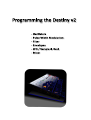
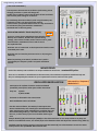
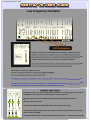
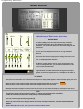
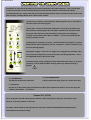
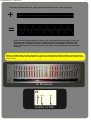
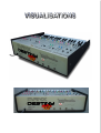
1 Contents
Contents
Getting Started
Introduction.................................................................3
Installation...................................................................4
Adjusting Parameters...................................................4
Programming the Destiny v2
Oscillators.....................................................................6
PWM.............................................................................8
Filter.............................................................................9
Envelopes....................................................................10
LFO / Sample & Hold....................................................14
Mixer...........................................................................15
Destiny v2 Controls
Keyboard modes, portamento, bend range..................17
LFO 2,...........................................................................17
Program saving and loading..........................................18
Continuous Control & Midi Learn..................................19
Zoom out......................................................................19
Appendices
Appendix One: Audio Filters..........................................21
Appendix Two: Troubleshooting....................................24
Appendix Three: Info for users.......................................25
User Guide last updated: 01-03-2015
3 Getting Started
2 note that if you are new to synthesis, parts of this user guide may appear to be ‘a bit heavy’.
Please
Don’t worry, once you start turning knobs and flicking switches on the Destiny v2, it will all start to make sense.
Introduction
Congratulations on acquiring the Manx Destiny v2 synthesizer. The Destiny is inspired by a real vintage analog synth,
a splendid instrument originally produced some 40 years ago, whose classic sound can be heard on countless
popular recordings. It is still used today, by those fortunate enough to own one despite their rarity.
The layout of the controls can seem a little confusing at first glance, but once you spend a bit of time with the Destiny,
you will see that it’s fairly consistent with the standard 2 VCO subtractive synthesizer configuration, but with extensive
modulation capabilities. This means that it is fairly quick and intuitive to work with, whilst allowing for a good range
of sounds.
Manx Synthesizers originally started out as a vehicle to test out novel oscillator designs, whilst looking into the possibility of
providing digital oscillators with more ‘power.’
These designs share much ‘DNA’ with what lies under the hood of Manx instruments today. However, we
subsequently shifted our attention onto the filter and envelope sections, which we felt, were still being somewhat
‘trashed’ by real analog gear.
For patches which feature an open filter and bland EG settings, the Destiny v2 does sound similar to its predecessor, the
Manx Destiny v1. However, patches with significant filtering and bold EG settings are probably the most commonly
used synth sounds out there; and these are a kind of sounds in which the Destiny v2 can now excel.
General features
Switchable between monophonic (1 voice) and duo-phonic (2 voices).
Midi Learn for all parameters; Patch memory system with full library.
Two LFOs, Sample & hold, Ring modulation, PWM, Sync, much more.........
General information
The Destiny v2 has no on-board effects - its output is mono.
External effects must be used if you need stereo imagery, or layer 2 Destiny v2s
together, then pan.
-
-
4 Getting Started
Installation
Please extract the contents of your downloaded RAR file to your VST plugins folder.
If you are installing the demo version of the Destiny v2, please copy both the dll file and the folder into
your VSTplugins folder: If this folder is absent when the Destiny v2 is launched, the instrument will attempt
to create one automatically, but this may be undermined by Windows security systems.
If you have already installed the demonstration version and are upgrading to the retail version
(recommended), the computer will ask if you want to overwrite an existing file (since the demo and
retail versions have the same file name). Click Yes .When upgrading from the demo version you don’t
need to copy the Destiny v2 folder since it contains the same stuff.
(Note: if for some reason you can’t open the RAR file, please let us know and we can send the dll &
folder to you directly, via email.)
Patch data saving
Please note that when you save a patch into the Destiny v2’s internal patch memory system, all variables
are saved, including the test tone setting and master tune controls.
Adjusting parameters
For continuous parameters, click and drag the respective knob or slider.
For switches, click repeatedly on the switch area to flick through the available settings.
IMPORTANT!
You can achieve very fine adjustments for the knobs by clicking on the knob and dragging the cursor
away from the knob horizontally for a good distance before adjusting the knob by moving vertically.
This advice is only pertinent to the Bend Range Control.
6 Programming -Oscillators
The Destiny v2’s oscillators
2
1
1
When playing a guitar, the sound produced originates from the
strings. In the case of a synthesizer, the basic
sound comes from a section called the ’oscillator’. Just as a
guitar can have twelve strings instead of six, so a
synthesizer may feature two oscillators instead of one. This is
the case with the Manx Destiny v2.
Having two oscillators instead of one can give you a fatter
sound, especially if the two oscillators are set two be
slightly out of tune.
1
1
1
TUNING - Oscillator frequency (1)
The Destiny v2 features two fully loaded oscillators; you can control the pitch of each, from the oscillator
panel shown above.
Both oscillators have course and fine sliders for pitch control, under the heading ‘frequency’.
There is no master tune control on the Destiny v2, but its very quick to dial up desired pitch using the four
sliders in the oscillator sections - the Destiny’s sliders have a long ‘travel’.
OSCILLATOR SYNCHRONIZATION (2)
Normally, the two oscillators are free running (simulated); they operate independently. This means
that when you press a key multiple times, the resulting sound may not be exactly the same each time,
because the oscillators will interact with each other differently each time.
However, when Oscillator Sync is turned on, the 2nd oscillator will be forced to reset to the
start of its wave-cycle, every time the 1st oscillator naturally works round to the start of its
cycle.
If your new to synthesis and this sounds complex - don’t worry. Simply try it out - you will
recognise the kind of sounds sync’ing can produce since they appear everywhere in
popular recorded music.
7 Programming -Oscillators
( OSC SYNC CONTINUED )
The important characteristic of oscillator synchronising is that
changing oscillator 2’s pitch will change the
timbre of the oscillator section but the pitch of both oscillators
will track the pitch setting for oscillator 1.
3
By modulating the 2nd oscillator’s pitch using the Destiny v2’s
envelopes or LFOs, sync’ing will provide another
means to have your patch’s timbre evolve as a key continues to
be held down (along side with filter modulation described later in the user guide).
OSCILLATOR ONE KEY-TRACK ON/OFF (3)
There are several factors which determine the pitch of the
Destiny v2’s oscillators, besides their specific tuning
settings; other factors include; master-octave control , pitchbend midi data, modulation sources and of course
the keyboard itself.
Oscillator Two is ‘hard wired’ to the keyboard and tracks it with
a standard piano scale.
Oscillator One can have key-track turned on or off, using the
switch (3).
When key-tracking is turned off, oscillator One’s pitch is
controlled by the frequency sliders and pitch modulation
sources.
WAVEFORMS
Each of the Destiny’s two oscillators can output 2 different wave forms - sawtooth & pulse.
There are no switches to switch between the two waves; The oscillators output both simultaneously and
they can subsequently be routed as to your requirements in other sections of the synth.
FM stands for ‘Frequency
Modulation’!
OSCILLATOR MODULATION
Two aspects of oscillator function can be modulated
(constantly varied) from other parts of the instrument.
They are
1) Pitch
2) Pulse width.
The latter is discussed in the next section.
5
7
Pitch modulation works as follows:
Like the main oscillators, the Destiny’s LFO outputs two
waves simulaniously. Use switch (4) to switch between them
when applying LFO->pitch modulation to oscillator One. Set
the amount using slider (5). The LFO is discussed in detail
later on, so don’t worry if you’re not familiar with it right
now.
4
6
8
Sample & Hold (S/H) and Envelopes (ADSR) are also discussed later on. For now, suffice to say they can
both be a modulation source; use switch (6) to select between them and adjust the amount using slider (7).
Oscillator Two has similar controls, but please note that switch (8) can select between an LFO sine wave
and input from the S/H MIXER. More on that later.
8 Programming -PWM
Pulse Width Modulation
Both of the Destiny v2’s oscillators output pulse waves, which looks like this:
The pulse waves have a feature which the sawtooth waveforms don’t have; The peak to trough
ratio can be adjusted. We do this using a parameter known as ‘pulse width’.
Pulse Width
Pulse Width increased
This is a superb feature for two reasons:
Firstly, one wave shape - pulse - becomes an infinite number of wave shapes; all pulse waves with
different pulse widths.
The second reason is even more useful;
Because pulse width is a continuous variable, we can modulate it (vary it) in real time, using either
LFOs, envelopes (see later sections), or key tracking.
The controls labelled ‘WIDTH’ set the pulse width for
each oscillator. (1)
If the oscillator’s saw wave is patched in for audio output, the
pulse wave can’t be heard and so the settings here will have
no effect.
2
The actual Pulse width can be made to fluctuate around the
point set by the ‘WIDTH’ slider, by an amount
set by the ‘MOD’ slider - this stands for ‘Modulation’.(2)
The modulation source is selected using the switch below(3),
either LFO Sine wave or Envelope two (envelopes are described
later.)
1
1
3
4
9 Programming -Filter
The Destiny v2’s Filter
2
1
If your not already familiar with audio filters, please
refer to our basic introduction in Appendix #1.
3
5
7
9
4
6
8
The Destiny v2 has both a high-pass and a low-pass
filter. The high-pass filter can not be modulated and
only has one control; Frequency (3).
VCF FREQ (1) is the main cut-off control for the lowpass filter, with associated resonance, (2).
7
8
CAUTION: Turning up the resonance can lead to a profound increase in
sound volume, perhaps unexpectedly. Please consider both your speakers
and your ears and use this feature cautiously.
FILTER MODULATION
The controls labelled 5 - 9 control modulation of the filter cut-off:
Switch (4) - Select between modulation sources; Sample and Hold, or keyboard tracking.
Slider (5) - Attenuate source from (4).
Switch (6) - Select between modulation sources; Sample and Hold, or LFO sine wave.
Slider (7) - Attenuate source from (6).
Switch (8) - Select between modulation sources; Envelope One or Envelope Two.
Slider (9) - Attenuate source from (8).
Envelopes are discussed in the next section, including a section on envelope filter clipping.
10 Programming -Envelopes
The Destiny v2’s envelopes
Attack
Decay
Sustain
Release
The Destiny v2 has two ADSR type envelopes.
Envelopes are triggered when a key is depressed; from this point the output of the envelope (used for
modulation) will develop over time in a predictable profile, defined by the user, using controls in the
envelope section. The configuration of these controls varies from one instrument to another, but a
popular standard which emerged early on is to have four controls - Attack, Decay, Sustain & Release.
The following graph shows how these four controls operate on the envelopes output:
OUTPUT
Key is released
SUSTAIN
ATTACK
Key is pressed
DECAY
holds this level
indefinitely,
until key is released
TIME
RELEASE
11 Programming -Envelopes
The Destiny v2 has two envelopes, both triggered simultaneously by depressing a key. The output of these envelopes
can be assigned to various parts of the synth; pitch, volume, filter cut-off, and Pulse-Width:
Switchable: Envelope 1
or Envelope 2 to Filter
cut-off.
Envelope 2 to Pitch
Switchable: Envelope 1
or Envelope 2 to VCA
(volume output)
Envelope 2 to Pulse
Width
The default configuration for the Destiny v2 is to have envelope 1 control filter cut-off and/or other attributes
such as pitch, while envelope 2 is used exclusively to control volume. However, both envelopes can supply either
destination, as required.
12 Programming -Envelopes
8
AUTO REPEAT
1
2
Normally, the envelopes are triggered by key presses,
but using switches (1) & (2) you can set up each
envelope to be automatically triggered at regular
intervals by the LFO (auto repeat). The switch labelled
͚kybd repeat (3), if set in its upper position, will cause
this LFO auto repeat for envelope 2 to occur only
when a key is pressed.
3
Self-Compensating Sustain Level
CAUTION: If you reduce the Destiny v2 envelope’s SUSTAIN amount, the peak of the envelope’s output can actually
rise - the Destiny v2 attempts to recover overall volume level . This helps to offset any loss of volume which the
patch might incur due to the reduced sustain setting.
However, at very low sustain settings, the effect can be quite dramatic.
If an envelope which is controlling volume is subject to a reduction in sustain level,
PLEASE PROCEED CAUTIOUSLY in order to protect equipment and prevent ear damage.
ENVELOPE TO FILTER CLIPPING
Please note that the maximum output from either of the Destiny v2’s envelopes exceeds the highest cut-off frequency
setting (all frequencies allowed through) by a wide margin. This is deliberate and can be used to refine a
cut-off envelope profile around its peak, as shown below:
Envelope to filter slider set so that the
maximum envelope output is less than
max cut-off (all frequencies allowed through)
Max cut-off
Envelope to filter slider set so that the
maximum envelope output exceeds
max cut-off.
Max cut-off
In the second example, because the peak is ‘clipped’, the filter remains fully open for a longer period
and this will have a dramatic effect on the sound.
Please note that adding filter cut-off manually, in addition to envelope output, will further intensify this
effect since the two sources (cut-off slider & envelope output) are simply added together.
13 Programming -Envelopes
SHORT ATTACK TIMES
At extreme settings, the peak of an Destiny v2 envelope can be so snappy that it becomes important to co-ordinate
the attack times of the two envelopes, in order to prevent the filter from peaking after the volume has decayed
to sub-optimal levels. This is really only an issue when you have some moderate attack time on the filter envelope,
zero attack on the volume envelope but a swift decay on the latter. The following diagram illustrates the issue:
Volume envelope
Filter envelope
The brightest part of the sound,
defined by the filter envelope peak,
is compromised because the volume has
already decayed into the background.
Attack
Decay
One solution is to add a little bit of attack time to the volume envelope as well. (Increasing volume
‘decay’ time will also solve the problem but this will drastically change the nature of the sound!)
One might be concerned that adding some attack time to the volume envelope might ‘blunt’ the sound and
leave it with out much punch. In the case of the Destiny v2, this concern is unfounded, because at low settings, the
envelope’s attack is loaded toward the end of the attack phase - the following diagram will hopefully make
this clearer:
Volume envelope
Filter envelope
Attack
Decay
At low attack settings, the Destiny v2’s envelopes’
attack profile is not linear; It rises very steeply
indeed, to begin with, before slowing down and
rounding off. Right at the end, it speeds right up
again, to form a peak.
This gives you the sonic quality of a hesitant attack,
without losing too much in the way of punch. This
characteristic is not exhibited at higher attack
settings and will not be noticeable if decay times
are long. However, with short decay times, small
attack adjustments can have a big effect on a
preset’s perceived loudness.
Even in the case that the filter envelope’s attack is set to zero, adding a small amount of attack to
the volume envelope can significantly increase a sounds punch, because the volume’s peak lingers for
more time overall, whilst the decay is still abrupt and dramatic.
Again, if sustain is set to high, or decay is slow, then the effect described above will not be noticeable.
Increasing sustain level affects the decay time .......
In fact this is an illusion - the decay time itself remains the same but with a higher sustain level,
the attenuation from peek to sustain is reduced so the decay appears to be less pronounced.
Simply readjust the decay time to compensate for this.
Changes to resonance setting may similarly affect perceived time; again, simply readjust the decay
setting to compensate if required.
14 Programming -LFO / S&H
Low Frequency Oscillator
LFO Destinations
Just like the Destiny v2’s main oscillators, the low frequency oscillator (LFO) creates
waveforms. Unlike the main oscillators, the LFO is not influenced by which key has
been depressed; the frequency is controlled by the slider labeled ‘LFO FREQ in the LFO
section of the instrument and it can go down to sub-audible frequencies.
The purpose of the LFO is to provide a cyclic control output and it can be sent to various
places, in a similar way to the envelope generators discussed earlier.
The Destiny’s LFO only has one slider, frequency.
However, it outputs two waveforms simultaneously; Sine and Square.
These can be selected between at the point of destination.
The Destiny v2 actually has two flexible LFO’s; the second one appears in the Destiny v2 Control Section, described later.
The Destiny v2’s second LFO can only provide a sine wave. It can control ocilator pitch and so can produce a vibreto effect.
The important thing about LFO 2 is that its intensity is scaled by modulation wheel data.
SAMPLE AND HOLD
Sample & hold produces a series of (generally random) values by sampling signals input into the
S/H MIXER at certain points in time. These points in time can either be:
1
2
6
(a) periodic time intervals, the frequency of which are determined by the LFO Speed
or
(b) triggered by the keyboard.
Use the switch labelled LFO TRIG / KEYB TRIG to select either (a) or (b). (5)
Use sliders (1) & (2) to control what is input into the s/h mixer, along with their corresponding
switches underneath (3)(4).
3
4
5
The OUTPUT LAG slider (6) causes the sample & hold to glide from one sampled value to another.
15 Programming - Mixer Section
Mixer Section
Much of the routing performed on the Destiny v2 is
achieved using the mixer section, shown here:
AUDIO MIXER
8
Use sliders (2)&(3) to mix the output of the Destiny’s oscillators.
The switches below allow you to select between saw and pulse
waveforms - you cannot have both at the same time coming into the
audio mixer.
You can mix in an independent noise source or ring modulation
effect (1).
1
2 3
4
5
6
Noise is like the sound you might get if an analog radio is left out of
tune - a completely random waveform.
7
The Destiny v2 offers ‘white’ and ‘pink’ noise varieties; pink is the
courser sounding of the two - you can switch between them in the
control section, described later.
Ring modulation is an effect derived from mixing the VCOs output
together such that the amplitude of one is multiplied to the other. It
produces a ‘Dalek’ type of effect.
VCF MIXER
The inputs here control filter cut-off. Note that these inputs are simply added together, so filter envelope clipping can occur.
Slider (4) feeds the filter with modulation from either Sample & Hold MIXER, or key-tracking.
Slider (5) feeds the filter with modulation from either Sample & Hold, or LFO sine wave.
Slider(6) controls the envelope’s influence on the filter and you can select either envelope 1 or envelope 2 as the source.
VCA
The Destiny v2 does not have a master volume. It’s output level is controlled by an amplifier
inside the instrument, known as the ‘VCA’ (Voltage Controlled Amplifier).
You can control its gain directly using slider (8).
Slider (7) controls how much VCA gain will be affected by envelope modulation, selectable between ADSR1 &
ADSR2.
When slider (8) is set to zero, slider (7) acts as a master volume control.
17 Control Panel
The Destiny v2 control panel provides all you need to effectively control the synthesizer. Here, you will find
a noise source selector, test tone facility, duophony mode selector facilities to load and save patches,
a second LFO and more. Please note that apart from the patch memory menus, all controls in this section save
with the patch, including Master-Tune and Test-Tone controls.
(1) Noise Source Selector: selects between white and pink noise, as described in
the mixer section of the user guide.
1
3
5
6
2
(2) Test Tone: Use this to check that the Destiny is correctly set up within your
host software. If pressing keys does not yield a sound but the Test Tone can be
heard, then the chances are that the Destiny’s midi input is not configured
correctly. The test tone emits a pitch of middle C ʹ. You can thus check that the
Destiny’s tuning is correct.
4
(3) Monophonic / Duophonic selector ʹ switches between monophonic (1 voice, 2
VCOs) and duo-phonic operation (2 voices, 1 VCO each - reverts to 2 VCOs if only
one note is being played).
(4) Legato/re-trigger ʹ when set to re-trigger, this re-triggers the envelopes every
time a new key is depressed, even if the last key is still being held down. This is
not applicable when in duo-phonic mode.
7
8
9
Note that vintage analog synthesizers often did not have this option; it can be of
great help , but can lead to audible ‘clicking’ when very extreme filtering is
applied.
( 5 ) PORTAMENTO
( 6 ) PITCH BEND RANGE
The Destiny v2 features portamento.
Controls pitch bend range, from 0 to 1 octave each way.
( 7 ) Transpose
Use this to set the octave range of the Destiny v2 (finer pitch adjustments must be carried out using the
oscillator pitch sliders. +/- 2 Octaves.
Vibrato LFO (LFO 2)
This is designed to provide vibrato (pitch oscillation ) while freeing up the Destiny’s main LFO for other
purposes. It can only produce a sine wave.
The speed is determined by slider (8) while the intensity is determined by Modulation Wheel position,
factored by the sensitivity knob (9).
18 Control Panel
Patch menus:
Click on the white button labelled ’Patch ‘ in order to select a patch. Note that if you make
alterations to a particular patch, those alterations will remain in effect if you select a different
patch, but will not be present if you launch the Destiny v2 on another occasion. Copying patches
from one memory slot to another can be achieved by clicking on the menu labelled File. This
menu also includes options for saving & loading either individual patches (presets) or the
entire bank, as discrete files on your hard drive.
19 Midi Learn / Zoom
Continuous Control & Midi Learn
Right click on any switch or knob to bring up a menu which will allow you to either manually assign a
continuous controller number or use the Midi Learn facility:
Simply click midi learn and then adjust the control on your midi control keyboard which you would like
to associate with the Destiny v2 parameter.
When you save your song the continuous controller assignments will be saved and will be functional
when you reopen it later.
If you save a preset or bank, the controller assignments will be saved with the bank or preset.
If you open a previously saved bank or preset, the current controller assignments will be lost and those
contained in the loaded bank / preset will come into effect.
If you open a single preset, the controller assignments saved with that preset will be loaded into the
Destiny v2 and propagated across all of the patches in the Destiny v2 ʹ you can not have controllers
assigned differently for different patches.
When you open a new song and launch the Destiny v2, the default factory bank is automatically loaded
which doesn’t contain any controller assignments at all. But you can then load up a preset (which you
saved previously) which has the controller assignment configuration that you wish to use, into an empty
slot. The controller assignment configuration will then apply to all patches in the Destiny v2. This allows
you to work with many different configurations according to your needs at any given time.
Zoom Out
Clicking on the discrete black hotspot in the top left of the programming view-port will cause the
Destiny v2 to ‘zoom out’ revealing its appearance from a distance. You can not program the instrument from
the zoomed out view - but you can simulate ‘stepping back’ from the instrument whilst consolidating
one’s thoughts.
Click on he image to return to the programming view-port.
21 Appendix One - Audio filters
Appendix One:
The basics.......
You may think of a synthesizer filter as being rather like a single ‘tone’ control that you might find on a
home audio system such as a personal CD player. However, it’s an extremely intense tone control; so much so
that when the tone control is turned down to its minimum setting, the sound disappears all together!
Synthesizer filters and EQ devices allow us to adjust the balance of frequencies in a sound; bass refers to low
frequencies and treble refers to high frequencies. Frequency is an interesting subject and is discussed below.
intensity (volume)
intensity (volume)
BASS
Frequency
TREBLE
BASS
TREBLE
Frequency
Tone control set to minimum
Tone control set to fully open
Please note that this type of EQ cannot remove any
frequencies entirely
Graphic view of the action of a standard audio player tone control
Cut off
intensity (volume)
BASS
intensity (volume)
Cut off
Frequency
BASS
TREBLE
Cut-off set just up from midway (no resonance)
Please note that a little way beyond the cut off point, frequencies are
Frequency
TREBLE
cut-off set just up from midway, with resonance applied
removed entirely.
Graphic view of the action of a synthesizer low pass filter
RESONANCE
The last of the graphs above introduces another feature of synthesizer filters - resonance. On the Destiny v2 filter,
the resonance is controlled by the slider labelled ‘REZ’. When resonance is applied, frequencies around the
cut-off point are emphasised, as shown in the graph. At very high settings, this emphasis results in an audible
high pitched squeal, which can be used to great effect.
CAUTION: Turning up the resonance can lead to a profound increase in sound volume, perhaps unexpectedly.
Please consider both your speakers and your ears and use this feature cautiously.
22 Appendix One - Audio filters
Frequency and Waveforms...................a little bit of magic!
8
It just so happens that sound waves don’t like to propagate through air in any form other than a sine
wave.
It stands to reason; air which is of a higher pressure because of a sound wave will want to expand
quickly, but this urgency will dampen off as the pressure returns to normal, and a subsequent rebound in
the other direction will complete a sign wave pattern. Similar physics are at work in a swinging pendulum
- it will only prescribe a sine wave pattern.
However, we can clearly hear square or sawtooth shaped waves coming out of a synthesizer. And,
although they don’t commonly occur in nature, you can hear these waves coming off of electrical
installations and other machinery as well. How is this so?
The answer lies in adding sine waves together - in other words, hearing more than one sine wave
at the same time. Consider the diagram below, which graphically illustrates hearing a loud low pitched
sine wave, and a much quieter high pitched sine wave, both at the same time:
+
=
If that appears to be intuitive, this instance may not. Look what happens when we decrease the
gap between the high and low sine waves, so now they are of a similar but not identical pitch:
+
=
23 Appendix One - Audio filters
If we add yet another sine wave, higher pitched and quieter than the others, we get this:
+
=
As you can see a regular waveform which is not a sine wave begins to emerge. It turns out
that when many different sine waves are added together, the resulting wave-shape can be
anything at all. In complex cases such as speech, you are still hearing a ‘chorus’ of sine
waves, but in this case, the relative volumes and pitches of those wave would be constantly
changing.
When an equalizer (EQ) or filter is applied to a sound, it is adjusting the relative balance of the component
sine waves in that sound. A sound which is bright will have louder high frequency sine waves than a sound
which is dull.
An EQ device
Destiny v2 filter
24 Appendix Two - Troubleshooting
Appendix Two
TROUBLESHOOTING & KNOWN ISSUES
These issues apply to Destiny v2 version 1.1 and may be resolved in subsequent
versions.
Defaulting to Patch 1, upon start-up:
With some VST host programs, when you reopen a song which contains an instance of the Destiny v2, for
some reason the host software tells the Destiny v2 to default to the first patch. So, for example, if you’re
working on a song which includes the Destiny v2 set at patch number forty (which has been tweaked to
your liking), upon saving and reopening the song, the Destiny v2 is not set as it was when you saved, but
instead is set at patch number one. This is a serious irritant because the recall of all settings within a
particular song is one of the best features of virtual studio technology.
This problem is not unique to Manx Synths and only occurs under certain conditions with particular
hosts. None the less, we will look at resolving this issue in future updates.
If you experience this problem, please note that the settings you applied to the patch you were
working with will have been properly saved with the song, so there should be no problem if your song
includes several Destiny v2 patches, controlled by ͚program change events.
Setting a program change key in your host program will ensure that the Destiny v2 returns to where you left it.
Alternatively, you can apply the following work around:
1 ʹ copy the patch you are working with into patch#1 memory slot using the Destiny v2͛s ‘patch menu’ button.
2- Save your song. When you reopen it later, if the Destiny v2 defaults to patch 1, its no longer a
problem and everything will be just as it was when you saved.
File Menu buttons not working properly
People may find that on some systems, the buttons which increase and decrease the numbers in the
data fields presented in the file menu do not respond properly. If this is the case, simply fill the data fields
in manually.
If you click ‘load patch’ and nothing happens, just click ‘load bank’, than hit ‘cancel’ and then return to
load patch again.
25 Appendix Three - Information for users
Appendix Three-
Information for users
CREDITS
We would like to thank the following contributors:
Jeff McClintock.
David Haupt, Daz Disley, Rob Herder, Rick Jelliffe, Christian-W. Budde & Chris Kerry, who
have provided code used in Manx synthesizers.
END USER AGREEMENT
You must agree to the following terms and conditions before installing and using
the Manx Destiny v2 Demo version:
You may not attempt to disassemble or alter the Destiny v2 demo DLL or accompanying files in any way.
You can distribute the Destiny v2 demo provided you do not directly profiteer from the distribution and
credit the Destiny v2 as a Manx product.
You must agree to the following terms and conditions before installing and
using the Manx Destiny v2 retail version:
After purchasing the Destiny v2 retail version you are licensed to use this on up to a maximum of 3 computers
provided that you are the sole owner and user of these computers.
You may not attempt to disassemble or alter the Destiny v2 DLL or accompanying files in any way.
Please do not distribute the Destiny v2 DLL to other individuals.
Copyright Manx Synthesizers 2014
www.manxsynthesizers.com
Thank you for
supporting Manx.
Other Manx Instruments:
Bit 100 v2
MM-2
XS-4
Destiny v2
Gigmate v2
http://www.manxsynthesizers.com/
Copyright 2015 Manx Synthesizers