1
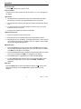
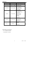
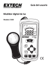
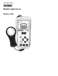
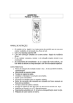
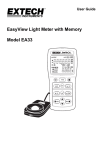
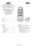
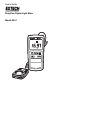
User's Guide
EasyView Digital Light Meter
Model EA31
Introduction
Congratulations on your purchase of the Extech EasyView Digital Light Meter
which measures the amount of light falling on a surface (illuminance) in Footcandles or Lux. This device measures up to 20,000 Fc and 20,000 Lux. Careful
use of this meter will provide years of reliable service.
Specifications
Units
Ranges and
Resolution
Lux
20.00, 200.0, 2000,
20.00kLux
Foot-candles
20.00, 200.0, 2000,
20.00kfc
Accuracy
± (3% rdg + 0.5% FS)
±( 4% rdg + 10 digits) if > 10,000 lux/fc)
General Specifications
Display
Over range indication
Spectral response
3-1/2 digit, 2000 count LCD
LCD displays ‘OL’
CIE photopic (CIE human eye response curve),
Cosine corrected
6%)
Spectral accuracy
CIE V2 function (f’1
Measurement Repeatability ±2%
Calibration
Calibrated to a standard incandescent lamp at
color temperature 2856ºK
Temperature coefficient
±0.1% per oC
Sampling rate
2.5 times per second
Photo detector
Silicon photo-diode and spectral response filter
Operating conditions
Temperature: 32 to 104oF (0 to 40oC); Humidity: <
80% RH
Storage conditions
Temperature: 14 to 140oF (-10 to 50oC); Humidity:
< 80% RH
Dimensions
5.91 x 2.8 x 1.4" (150 x 72 x 35mm)
Weight
Approx. 11.3 oz. (320g) with battery
Photo Detector Dimensions 3.62 x 2.36 x 1.14” (92 x 60 x 29mm)
Detector cable length
3’ (91cm) approximately
Low battery indication
“BT” appears on the LCD
Power supply
6 ‘AAA’ cells; Battery life approx 400 hours
2
EA31 V1.1 02/03
Meter Description
1.
2.
3.
4.
5.
6.
7.
LCD display
Range button
Power ON/OFF button
lux / fc selection button
Data HOLD button
MAX/MIN button
Photo sensor (lens cover not shown)
(Tripod mount on rear of sensor)
Note: Battery compartment is located
on the rear of the instrument
Spectral Sensitivity
3
EA31 V1.1 02/03
Operation
Power ON or OFF
Press the
button to turn power on or off.
Units of measure
Press the lux / fc button to select the unit of measure. “fc” or “lux” will appear in
the display.
Light sensor
1. The light sensor is attached to the meter with a coiled cable which allows
placement of the sensor up to approximately 3 feet from the meter.
2. The light sensor is a silicon photo diode and resides under the white domed
lens.
3. To protect the lens from scratches, keep the protective cap on the sensor
whenever the unit is not in use.
4. The back of the sensor has a tripod mounting hole.
Taking measurements
1. Remove the protective cap from the sensor.
2. Place the sensor in a horizontal position at the measurement location.
3. Read the light level on the display. If the light measurement is out of range an
“OL” indication will appear on the display. If the ‘OL’ appears, select a higher
range by pressing the RANGE button.
MX MN Function
1. Press the MX/MN button once to put the meter in MX/MN mode. The meter
will now display the highest reading that occurs while the function is enabled.
The “MAX” icon will appear in the display.
2. Press the MX/MN button again to display the lowest reading that occurs while
the function is enabled. The “MIN” icon will appear in the display.
3. Press MX/MN again to toggle between the MAX and MIN readings.
4. To exit the MX MN mode and return to the normal real time display, press
and hold the MX/MN button (2 seconds) until the MAX and MIN icons
disappear.
Data Hold
Press the HOLD button to freeze the displayed reading. The 'H' hold icon will
appear on the display. Press the HOLD button again to return to normal
operation.
4
EA31 V1.1 02/03
Reference
Foot candles
Lux
Typical Light Levels
>10000
>107600
1000 to 10000
10760 to 107600
Sunlight
Operating Table
Assembly (fine)
100 to 1000
1076 to 10760
Football stadium
Emergency room
Drafting table
Overcast day
Assembly (general)
Classroom
10 to 100
107 to 1076
Casual reading
Shipping area
Stairwell
Auditorium
ATM machine
1 to 10
10.7 to 107
Storage room
Building entrance
Parking lot
Highway
0 to 1
0 to 10.7
f
Full moon
Foot-candle / Lux conversion
1 lux = .09290 foot-candles
1 foot-candle = 10.764 lux
5
EA31 V1.1 02/03
Maintenance
Cleaning and storage
1. The white plastic sensor dome should be cleaned with a damp cloth when
necessary.
2. Store the meter in an area with moderate temperature and humidity (refer to
the operating and storage range in the specifications chart earlier in this
manual).
Battery Replacement
When the battery voltage is low the ‘BT’ symbol will appear on the display.
Replace the six (6) 1.5 ‘AAA’ batteries by removing the rear (center) battery
compartment screw and accessing the battery compartment. Observe polarity
when placing the batteries in the compartment. Ensure that the compartment
cover is securely fastened when finished.
Calibration and Repair Services
Extech offers repair and calibration services for the products we sell. Extech also
provides NIST certification for most products. Call the Customer Service
Department for information on calibration services available for this product.
Extech recommends that annual calibrations be performed to verify meter
performance and accuracy.
6
EA31 V1.1 02/03
Warranty
EXTECH INSTRUMENTS CORPORATION warrants this instrument to be free
of defects in parts and workmanship for one year from date of shipment (a six
month limited warranty applies on sensors and cables). If it should become
necessary to return the instrument for service during or beyond the warranty
period, contact the Customer Service Department at (781) 890-7440 ext. 210
for authorization or visit our website at www.extech.com (click on ‘Contact
Extech’ and go to ‘Service Department’ to request an RA number). A Return
Authorization (RA) number must be issued before any product is returned to
Extech. The sender is responsible for shipping charges, freight, insurance and
proper packaging to prevent damage in transit. This warranty does not apply to
defects resulting from action of the user such as misuse, improper wiring,
operation outside of specification, improper maintenance or repair, or
unauthorized modification. Extech specifically disclaims any implied warranties
or merchantability or fitness for a specific purpose and will not be liable for any
direct, indirect, incidental or consequential damages. Extech's total liability is
limited to repair or replacement of the product. The warranty set forth above is
inclusive and no other warranty, whether written or oral, is expressed or
implied.
Support Hotline (781) 890-7440
Tech support: Ext. 200; Email: [email protected]
Repair/Returns: Ext. 210; Email: [email protected]
Website: www.extech.com
Copyright © 2003 Extech Instruments Corporation.
All rights reserved including the right of reproduction in whole or in part in any
form.
7
EA31 V1.1 02/03