1
PowerStruXure
User’s Manual
Contents
Safety Information . . . . . . . . . . . . . . . . . . . . . . . . . . .1
Safety Warnings 3
Overview . . . . . . . . . . . . . . . . . . . . . . . . . . . . . . . . . .7
PDU with System Bypass 9
Symmetra 3-Phase UPS 12
NetShelter VX Enclosures 14
3-Phase Automatic Transfer Switch 16
Metered Rack-Mount PDU 17
Information Controller and Hub 18
Site Planning. . . . . . . . . . . . . . . . . . . . . . . . . . . . . . .19
PDU with System Bypass 21
Symmetra 3-Phase UPS 24
Emergency Power-Off Switch 26
NetShelter VX Enclosures 27
Installation . . . . . . . . . . . . . . . . . . . . . . . . . . . . . . . .29
PDU with System Bypass 31
Symmetra 3-Phase UPS 38
Emergency Power-Off Switch 42
NetShelter VX Enclosures 44
Cable Troughs, Partitions, and Ladders 47
Power Cables (Whips) 54
3-Phase Automatic Transfer Switch 58
Metered Rack-Mount PDU 60
Information Controller and Hub 63
System Start-Up. . . . . . . . . . . . . . . . . . . . . . . . . . . . .65
Start-Up Procedure 67
Contents
Communication Connection . . . . . . . . . . . . . . . . . . . 75
Information Controller and Hub 77
Configuration. . . . . . . . . . . . . . . . . . . . . . . . . . . . . . 87
Metered Rack-Mount PDU 89
Operation . . . . . . . . . . . . . . . . . . . . . . . . . . . . . . . . 97
System Operation 99
PDU with System Bypass 102
Symmetra 3-Phase UPS 116
3-Phase Automatic Transfer Switch 122
Metered Rack-Mount PDU 123
Information Controller and Hub 125
Customization . . . . . . . . . . . . . . . . . . . . . . . . . . . . 127
NetShelter VX Enclosures 131
Metered Rack-Mount PDU 142
Specifications . . . . . . . . . . . . . . . . . . . . . . . . . . . . . 145
PDU with System Bypass 147
Symmetra 3-Phase UPS 148
3-Phase Automatic Transfer Switch 150
Metered Rack-Mount PDU 151
Information Controller 152
Maintenance . . . . . . . . . . . . . . . . . . . . . . . . . . . . . 153
Symmetra 3-Phase UPS 155
Metered Rack-Mount PDU 161
Product Information . . . . . . . . . . . . . . . . . . . . . . . . 163
Warranty 165
Life-Support Policy 166
How to Obtain Service 167
How to Contact APC 168
Document Information 169
ii
User’s Manual—PowerStruXure Type B
Safety Information
Safety Warnings . . . . . . . . . . . . . . . . . . . . . . . . . . . . .3
Safety symbols used in this guide 3
General safety warnings 3
PDU with System Bypass 4
Symmetra 3-Phase UPS 5
Other components 5
Safety Warnings
This manual is intended for use by the following groups:
• Users
• Licensed electricians
• APC Field Service Engineers
• Qualified, APC-trained personnel
This manual indicates who must perform specific procedures. Failure to
follow the instructions in this manual could result in damage to property,
personal injury, or even death.s
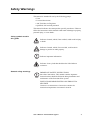
Safety symbols used in
this guide
Electrical
Hazard
Indicates a hazard, which, if not avoided, could result in injury
or death.
Indicates a hazard, which, if not avoided, could result in
damage to product or other property.
Warning
Indicates important information.
Note
Indicates a heavy load that should not be lifted without
assistance.
Heavy
General safety warnings
Note
IMPORTANT SAFETY INSTRUCTIONS
Save these instructions. This manual contains important
instructions that should be followed during installation and
maintenance of the PowerStruXure system.
INSTUCTIONS IMPORTANTES CONCERNANT LA
SÉCURITÉ
Conserver ces instructions. Cette notice contient des
instructions importantes concernant la sécurité.
User’s Manual—PowerStruXure Type B
3
Safety Information: Safety Warnings
Total Power Off Procedure:
Note
1. Set the Symmetra 3-Phase UPS System Enable switch to
the Standby or Off position.
2. Open the Symmetra 3-Phase UPS DC Disconnect
breaker.
3. Open the PDU with System Bypass Main Input breaker.
4. Open the DC Disconnect breaker of each XR Battery
Cabinet.
5. Disconnect the batteries in the Symmetra 3-Phase UPS by
pulling them out approximately one inch (25.4 mm) from
their normal position.
Electrical
Hazard
Hazardous, live parts inside the Symmetra 3-Phase UPS are
energized from the battery supply even when the AC power is
disconnected.
Hazardous, live parts may exist inside the PDU with System
Bypass due to the Symmetra 3-Phase UPS inverter even when
the AC power is disconnected. Test before touching any
electrical parts.
Warning
PDU with System Bypass
Electrical
Hazard
This equipment has been tested and found to comply with the
limits for a Class A digital device, pursuant to Part 15 of the
FCC Rules and the Class A limits for radio noise emissions
from digital apparatus set out in the Radio Interference
Regulations of the Canadian Department of Communications.
These limits are designed to provide reasonable protection
against harmful interference when the equipment is operated
in a commercial environment. This equipment generates, uses
and can radiate radio frequency energy and, if not installed
and used in accordance with the instruction manual, may
cause harmful interference to radio communications.
Operation of this equipment in a residential area is likely to
cause harmful interference in which case the user will be
required to correct the interference at his or her own expense.
Hazardous, live parts inside the PDU with System Bypass are
energized from the battery supply of the attached Symmetra
3-Phase UPS even when the AC power is disconnected.
Risk of Electrical Shock. No user serviceable parts inside.
Refer all servicing to an APC Field Service Engineer.
A licensed electrician must perform the following:
• Connection to the branch circuit.
• Connection of PDU power cords in addition to the
factory-installed power cords.
4
User’s Manual—PowerStruXure Type B
Safety Information: Safety Warnings
Warning
Changes or modifications to this unit not expressly approved
by the party responsible for compliance could void the user's
authority to operate the equipment.
The Branch Circuit conductors are secured to the Main Input
Circuit Breaker. Ensure that the circuit breaker terminals are
tightened to the torque specified on the circuit breaker's label.
Note
This product is intended for installation in a temperaturecontrolled (0o C–40o C), indoor area, free of conductive
contaminants.
Symmetra 3-Phase UPS
Electrical
Hazard
The Symmetra 3-Phase UPS contains an internal energy
source. Hazardous voltage can be present even when
disconnected from the utility power source.
All power wiring from the Symmetra 3-Phase UPS to the PDU
with System Bypass must be completed by an APC Field
Service Engineer.
A battery can present a risk of electrical shock and high shortcircuit current. The following precautions should be observed
when working on batteries:
• Remove all conductive jewelry such as chains, watches,
and rings.
• Use tools with insulated handles.
• Wear rubber gloves and boots.
• Do not lay tools or metal parts on top of the batteries.
Warning
Other components
When replacing batteries, replace with same number and type
as installed. For customer-supplied external batteries, see
manufacturer’s installation and safety instructions.
Automatic Transfer Switch, Metered Rack-Mount PDU, Information
Controller, and Information Controller Hub.
This equipment contains potentially hazardous voltages. Do
not attempt to disassemble the unit.
Warning
This equipment contains no user serviceable parts. Repairs are
performed only by factory-trained service personnel.
User’s Manual—PowerStruXure Type B
5
Overview
PDU with System Bypass . . . . . . . . . . . . . . . . . . . . . . .9
Front veiw 9
Front view (interior) 10
Rear view (interior) 11
Symmetra 3-Phase UPS . . . . . . . . . . . . . . . . . . . . . . .12
NetShelter VX Enclosures . . . . . . . . . . . . . . . . . . . . .14
Cable-routing equipment 15
NetShelter VX options 15
Expansion and mounting hardware 15
3-Phase Automatic Transfer Switch . . . . . . . . . . . . . .16
AP7701 16
Metered Rack-Mount PDU . . . . . . . . . . . . . . . . . . . . .17
Information Controller and Hub . . . . . . . . . . . . . . . .18
Information Controller Hub 18
Information Controller 18
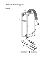
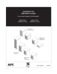
PDU with System Bypass
Front veiw
Power cable (whip)
Cable access holes
Display interface
Power cable trough
L21-20 outlet
Data cable trough
User’s Manual—PowerStruXure Type B
9
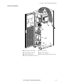
Overview: PDU with System Bypass
Front view (interior)
Information Controller Hub Wraparound maintenence
bypass panel
Information Controller
10
User’s Manual—PowerStruXure Type B
42-position circuit breaker
panels
Overview: PDU with System Bypass
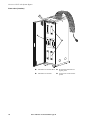
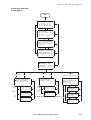
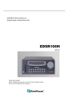
Rear view (interior)
➊
➋
➌
➍
➎
➏
➐
Main input circuit breaker
PDU transformer
Load test bank connector
EPO switch interface
PDU monitoring unit
UPS input and output connector cables
Fuses for external static switch
User’s Manual—PowerStruXure Type B
11
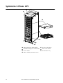
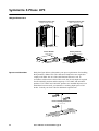
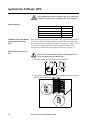
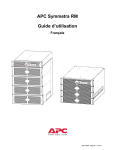
Symmetra 3-Phase UPS
ta
Sy
Qm
u m
Sy ick-Setr
Q m tart a TM
uic m
k-Setr Use 3
a -P
r
rt TMGu ha
U 3 id s
se -P e e
rG
uidha
e se
Main intellegence module (MIM)
Access for data cables
Redundant intelligence module (RIM) Static switch module
Power module
Battery module (four battery units)
12
User’s Manual—PowerStruXure Type B
Documentation tray
Overview: Symmetra 3-Phase UPS
Sy
Qm
u m
Sy ick- et
Q m Starra T
ui m t M
ck e U 3
-S tr ser ta a T G Ph
rt M u a
U 3 id s
se - e e
rGP
ui h a
de se
DC disconnect breaker
External switch gear monitoring card
System-enable switch
Display/computer interface card
System power supply cards Battery monitoring card
Available card slots
Reserved for future use
Network Management Card Extended-Run Frame card
User’s Manual—PowerStruXure Type B
13
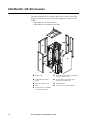
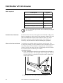
NetShelter VX Enclosures
The APC Netshelter® VX enclosure allows 42U (73.50 in) of storage
height for EIA-310, 19-inch, rack-mount equipment. It comes in two
models:
• AR2100BLK—the base enclosure
• AR2101BLK—an expansion enclosure
Frame posts
Ventilated split rear door for added
Adjustable horizontal
Quick-release side panels with
Vertical mounting rails
Ventilated roof
Skirt
Access on roof, sides, and base
braces
access in narrow aisles
locks (base model only)
Quick-release, ventilated,
reversible front door
14
User’s Manual—PowerStruXure Type B
Overview: NetShelter VX Enclosures
Cable-routing equipment
NetShelter VX options
Overhead ladders
Data partitions
Power cable trough
Options for this enclosure include the following:
• Stabilizer plate
• Bolt-down brackets
• Cable management devices
• Toolless mounting for some accessories
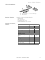
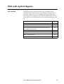
Expansion and mounting
hardware
Item
Quantity
AR2100BLK
AR2101BLK
Baying brackets
–
4
Vertical baying trim
–
1
M6 x 12 socket-head screws
–
8
M6 caged nuts
–
8
M6 × 16 mm Phillips/slotted
screws
60
60
Caged nut installation tool
1
1
M6 caged nuts
60
60
Plastic cup washers
60
60
Open-ended wrench (13/14 mm)
1
1
M5 Allen wrench
1
1
Door/side panel keys
2
2
Expansion hardware
Mounting hardware
User’s Manual—PowerStruXure Type B
15
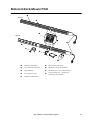
3-Phase Automatic Transfer Switch
AP7701
➋
➌
➊
➎
➍
➏
16
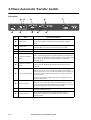
➊
Network Management Card (AP9617)
➋
Two NEMA L21-20 plugs (cords: 36 inches)
➌
NEMA L21-20R receptacle (cord: 36 inches)
➍
Rack-mount brackets
➎
Rear rail segments
➏
Front rail segments
User’s Manual—PowerStruXure Type B
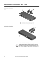
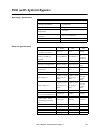
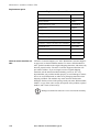
Metered Rack-Mount PDU
AP7601
AP7602
NEMA 5-20R outlets
Serial cable (940-0144)
Cord retension clip holes
Hardwire end cap (870-70803)
Digital display
Hardwire access cover (870-70804)
L21-20 power cord
Cord retention clip—AP7601:42;
AP7602:21 (870-70945)
NEMA L6-20R outlets
User’s Manual—PowerStruXure Type B
17
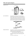
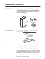
Information Controller and Hub
Information Controller
Hub
Information Controller Hub (32-port hub)
Rack-mount brackets (2) and screws (6)
Information Controller
Information Controller
Rack-mount brackets (2) and screws (4)
Note
18
The Information Controller and the Information Controller
Hub connect to powercords pre-installed in the PDU. These
cords are a 5-15 to IEC C13 and an IEC C13 to an IEC C14.
User’s Manual—PowerStruXure Type B
Site Planning
PDU with System Bypass . . . . . . . . . . . . . . . . . . . . . .21
Weight/Dimensions 21
Space considerations 21
Weight considerations 21
BTU Considerations 22
Operating conditions 22
Electrical requirements 23
Electrical specifications 23
Symmetra 3-Phase UPS . . . . . . . . . . . . . . . . . . . . . . .24
Weight/Dimensions 24
Space considerations 24
Weight considerations 25
BTU Considerations 25
Operating conditions 25
Electrical Requirements 25
Emergency Power-Off Switch . . . . . . . . . . . . . . . . . .26
Overview of EPO 26
NetShelter VX Enclosures . . . . . . . . . . . . . . . . . . . . .27
Weight/Dimensions 27
Space considerations 27
Weight considerations 27
PDU with System Bypass
Weight/Dimensions
PDU with System Bypass
1500 lb (680 kg)
Data Cable Troughs
85 in. (215 cm)
including power
cable trough:
89 in. (226 cm)
4.8 in.
(12 cm)
23 in.
(58 cm)
Power Cable Trough
23 in.
(58 cm)
34 in. (87 cm)
24 in. (60 cm)
Space considerations
7.2 in.
(18 cm)
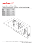
Study the figure below to determine your space requirements for
installing the PDU with System Bypass. The clearances listed below are
required to comply with Table 110-26 of the 1999 National Electric
Code. In accordance with section 110-26 of this code, the 36-inch depth
is required for all 120/208V products and the majority of 277/480V and
346/600V products. If 277/480V and 346/600V products are installed
adjacent to an uninsulated concrete wall, you must have a working depth
space of 42 inches. Consult your local code for additional requirements.
Floor-to-Ceiling Ventilation
>101 in. (236 cm)
Minimum Rear
Clearance
PDU
Minimum Front
Clearance
24 in.
(60 mm)
Weight considerations
36 in.
(91 cm)
34 in.
(86 cm)
36 in.
(91 cm)
Ensure that the floor and sub-floor can support the total weight of the
configuration when concentrated on the leveling feet. If you are placing
equipment on a raised floor, consult the flooring manufacturer for
loading requirements prior to installing equipment.
PDU with System Bypass Weight: 1500 lb (680 kg)
See “Weight considerations” on page 25 and on page 27 for weight
measurements for the Symmetra 3-Phase UPS and NetShelter VX
enclosures.
User’s Manual—PowerStruXure Type B
21
Site Planning: PDU with System Bypass
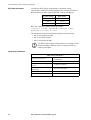
BTU Considerations
Consider the BTU ratings of equipment to determine cooling
requirements. Additional cooling equipment may be required. Refer to
the table below for BTU output of the PDU with System Bypass.
Product Voltage
BTU Output
208 V
4645
480 V
4617
600 V
3425
BTU was calculated with the following formula:
[(Load x % 2 x Mfg. specified load loss) + Mfg.
specified core loss] x 3.414
This calculation is based on the following Square D transformers:
• 208 V: 60T211HCUOCSW3
• 480 V: 60T3HCUOCSW3
• 600 V: 60T65HCUOCSW3
Note
The BTU output is higher while batteries are charging. Under
normal operating conditions, battery recharge periods are
relatively infrequent.
Operating conditions
PDU with System Bypass
22
Operating environment
Protected from water and conductive
contaminates
Temperature class (transformer)
Class H 220° C
Storage elevation (for shipping
by air)
33,000 ft (10 000 m)
Relative humidity (for operating
and storage)
95% non-condensing
Operating temperature
32–104° F (0–40° C)
Acoustic noise emission
Maximum 50 dB(A) at 1 m
User’s Manual—PowerStruXure Type B
Site Planning: PDU with System Bypass
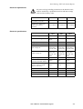
Electrical requirements
Electrical
Hazard
All power wiring, including connection to the branch circuit,
must be installed by a qualified electrician and must comply
with local and country codes.
208 V
480 V
600 V
Service distribution breaker
(provided by customer)
200 A
Conductors to main input
breaker (provided by
customer)
3/0 conductors #3 conductors #4 conductors
100 A
80 A
Electrical specifications
208 V
480 V
600 V
Step-down
Transformer type
Isolation
Step-down
Transformer configuration
Delta to
WYE
Delta to WYE Delta to WYE
Voltage requirements, nominal 208/120 V
208/120V
208/120V
Frequency
57–63 Hz
57– 63 Hz
57–63 Hz
Input voltage AC
3-phase
3-phase
3-phase
3-wire plus
3-wire plus
3-wire plus
ground, 208V ground, 480V ground, 600V
Output voltage AC
3-phase
4-wire plus
ground, 120/
208V
3-phase
4-wire plus
ground, 120/
208V
3-phase
4-wire plus
ground, 120/
208V
Output rating (full load)
40 kW
40 kW
40 kW
Maximum continuous input
current (at minimum mains)
155 A
67 A
54 A
Maximum continuous output
current + 125% overload
(Bypass mode only)
139 A
139 A
139 A
Output current, nominal
111 A
111 A
111 A
Input current, nominal
125 A
54 A
43 A
Internal static switch fuses
175 A
175 A
175 A
External output breaker
150 A
150 A
150 A
User’s Manual—PowerStruXure Type B
23
Symmetra 3-Phase UPS
Weight/Dimensions
Symmetra 3-Phase UPS
Empty 600 lb (265 kg)
Symmetra 3-Phase UPS
Full 1700 lb (775 kg)
82 in.
(208 cm)
24 in. (61 cm)
34 in. (87 cm)
Power Module
60 lb (26 kg)
Battery Module
4 × 50 lb (4 × 23 kg)
7 in.
(13 cm)
5.2 in.
13 cm
19 in. (48 cm)
Space considerations
28 in. (72 cm)
28 in. (72 cm)
4.25 in. (11 cm)
Study the figure below to determine your space requirements for installing
the Symmetra 3-Phase UPS. The clearances listed below are required to
comply with Table 110-26 of the 1999 National Electric Code. In
accordance with section 110-26 of this code, the 36-inch depth is required
for all 120/208V products and the majority of 277/480V and 346/600V
products. If 277/480V and 346/600V products are installed adjacent to an
uninsulated concrete wall, you must have a working depth space of 42
inches. Consult your local code for additional requirements.
Floor-to-Ceiling Ventilation
> 91 in. (230 cm)
Minimum Rear
Clearance
Symmetra 3-Phase UPS
Minimum Front
Clearance
23.5 in.
(60 cm)
24
36 in.
(91 cm)
User’s Manual—PowerStruXure Type B
34.3 in.
(87 cm)
36 in.
(91 cm)
Site Planning: Symmetra 3-Phase UPS
Weight considerations
Ensure that the floor and sub-floor can support the total weight of the
configuration when concentrated on the leveling feet. If you are placing
equipment on a raised floor, consult the flooring manufacturer for
loading requirements prior to installing equipment.
Symmetra 3-Phase UPS Weight:1700 lb (775 kg)
See “Weight considerations” on page 21 and on page 27 for weight
measurements for the Power Distribution Unit and NetShelter VX
enclosures.
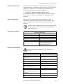
BTU Considerations
Consider the BTU ratings of equipment to determine cooling
requirements. Additional cooling equipment may be required. BTU
output of the Symmetra 3-Phase UPS is: 12,682 BTU/hr (North
America)
Note
The BTU output is higher while batteries are charging. Under
normal operating conditions, battery recharge periods are
relatively infrequent.
Operating conditions
Symmetra 3-Phase UPS
Electrical Requirements
Temperature range
32–104°F (0– 40°C)
Relative humidity
< 95%
Maximum elevation
0–10,000 ft (0–3048 m)
Nominal full load
12,682 BTU/h
Full load loss at nominal mains
3716 W
Operating environment
Keep ventilated; keep dust and
corrosive fumes away from the
Symmetra 3-Phase UPS.
.
Electrical
Hazard
Power wiring must be installed by an APC Field Service
Engineer.
Input voltage AC, nominal
3-phase 208 V
Output voltage AC, nominal
3-phase 208 V
Full load output rating (in maximum
configuration)
40 kW
Input frequency
60 Hz
Output frequency
Synchronized to mains in normal
operation; 60 Hz in battery operation.
Maximum input current
140 A
Maximum output current (125%
load—Bypass mode only)
139 A
Output current per phase, nominal
111 A
Output per neutral, nominal
(APC recommends the neutral to be
2 × phase.)
192 A
Input current, nominal
123 A
Input current limit
162 A
User’s Manual—PowerStruXure Type B
25
Emergency Power-Off Switch
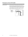
Overview of EPO
A remote switch (not included) is attached at the EPO interface in the
PDU with System Bypass. The EPO interface ➊ is connected to the
PDU with System Bypass Main breaker ➋ and to the Symmetra 3-Phase
UPS internal EPO switch ➌ (connection to the Symmetra 3-Phase UPS
is made during installation of PowerStruXure). When the remote EPO
Switch is enabled, power will be terminated at the PDU with System
Bypass and the Symmetra 3-Phase UPS, providing a single point for
emergency shutdown of the PowerStruXure system.
Switch
➊
PDU
➋
UPS
➌
26
User’s Manual—PowerStruXure Type B
NetShelter VX Enclosures
Weight/Dimensions
The American Power Conversion (APC) NetShelter® VX is a highquality enclosure for storage of industry-standard (EIA-310) 19-inch
equipment, which includes servers, voice, data, networking,
internetworking, and APC power protection equipment. Both the base
enclosure (AR2100BLK) and the expansion enclosure (AR2101BLK)
provide 42U of mounting space.
NetShelter VX
(base enclosure)
23.5 in. (59.60 cm)
Data Cable Troughs
81.5 in.
(206.92 cm)
4.8 in.
(12 cm)
23 in.
(58 cm)
Power Cable Trough
23 in.
(58 cm)
42.2 in.
(107.19 cm)
Space considerations
7.2 in.
(18 cm)
Study the figure below to determine your space requirements for
installing NetShelter VX enclosures.
Floor-to-Ceiling Ventilation
> 91 in. (231 cm)
Minimum Rear
Clearance
NetShelter VX
Minimum Front
Clearance
23.5 in.
(59.60 cm)
Weight considerations
30.0 in.
(76.20 cm)
42.2 in.
(107.19 cm)
23.6 in.
(59.94 cm)
Ensure that the floor and sub-floor can support the total weight of your
system configuration when concentrated on the leveling feet. If you are
placing equipment on a raised floor, consult the flooring manufacturer
for loading requirements prior to installing equipment.
Enclosure weight (empty): 359 lb (162.8 kg)
The rack is rated at 2000 lb for a static load, and 1400 lb for a dynamic
load. See “Weight considerations” on page 21 and on page 25 for weight
measurements for the PDU with System Bypass and the Symmetra 3Phase UPS.
User’s Manual—PowerStruXure Type B
27
Installation
PDU with System Bypass . . . . . . . . . . . . . . . . . . . . . .31
Tools required 31
Exchange side panels 32
Join the Symmetra 3-Phase UPS enclosure to the PDU
with System Bypass enclosure 33
Connection to be performed by a licensed electrician
only! 33
Connect main utility power 34
Symmetra 3-Phase UPS . . . . . . . . . . . . . . . . . . . . . . .38
Tools required 38
Position, level, and attach the Symmetra 3-Phase
UPS 38
Ensure that all power is off 38
Connect the PDU to the UPS
40
Emergency Power-Off Switch . . . . . . . . . . . . . . . . . .42
Choose a connection method 42
Connect a switch to the EPO interface 43
NetShelter VX Enclosures . . . . . . . . . . . . . . . . . . . . .44
Tools required 44
Position the enclosures 44
How to level an enclosure 44
How to stabilize the enclosure 45
How to join enclosures together 45
Cable Troughs, Partitions, and Ladders . . . . . . . . . . .47
Troughs and partitions for overhead wiring along
rows 47
How to install power cable troughs 48
How to install data cable partitions 49
Ladders for overhead wiring across rows 50
Installation: Contents
How to install ladders across rows 51
Power Cables (Whips) . . . . . . . . . . . . . . . . . . . . . . . 54
Route and attach overhead wiring 54
Wiring under the floor 57
3-Phase Automatic Transfer Switch . . . . . . . . . . . . . . 58
Placement 58
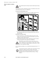
Attach mounting brackets 58
Disassemble segments of the adjustable bracket 58
Attach rear segments to the rack 58
Attach front segments to the switch 59
Mount the Automatic Transfer Switch in the
enclosure 59
Metered Rack-Mount PDU. . . . . . . . . . . . . . . . . . . . . 60
Mounting options 60
Toolless mounting 60
Bracket-mounting 61
Information Controller and Hub . . . . . . . . . . . . . . . . 63
Attach mounting brackets to the Controller and
Hub 63
Mount the Controller and Hub in the PDU with
System Bypass 63
30
User’s Manual—PowerStruXure Type B
PDU with System Bypass
Tools required
The following table lists all tools required for installation if your
configuration places the PDU with System Bypass adjacent to the
Symmetra 3-Phase UPS. For an installation in which the PDU with
System Bypass is not adjacent to the Symmetra 3-Phase UPS, you will
also need a selection of tools that are part of a standard electrician’s tool
set.
Tool Required
Supplied?
Standard screwdriver
No
Phillips screwdrivers (various sizes)
No
Metric socket wrench (13 mm) or adjustable open-ended wrench,
for connecting input and output wires between the PDU with
System Bypass and the UPS
No
Hex driver (3/16 in.)
No
Level
No
Open-ended wrench (14 mm) for adjusting the leveling feet of the
PDU with System Bypass
Yes
17 mm socket wrench
No
User’s Manual—PowerStruXure Type B
31
Installation: PDU with System Bypass
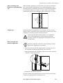
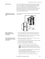
Exchange side panels
Before installing the PDU with System Bypass and the Symmetra
3-Phase UPS, you will need to exchange side panels so that the adjacent
panels will have matching holes for joining the enclosures together and
for routing input and output wiring between them. Perform these steps
before moving the enclosures to adjacent positions.
1. Remove the side panel from the side of the
Symmetra 3-Phase UPS that will be adjacent
to the PDU with System Bypass in your
planned configuration. (For instructions on
removing side panels, see “How to remove
and install the side panels” on page 131.)
2. Remove the side panel from the side of the
PDU with System Bypass that will not be
adjacent to the Symmetra 3-Phase UPS.
3. Install on the Symmetra 3-Phase UPS the side panel (with the prepunched hole) that you removed from the PDU with System Bypass
in Step 2.
4. Install, on the PDU with System Bypass, the solid side panel that
you removed from the Symmetra 3-Phase UPS in Step 1.
32
User’s Manual—PowerStruXure Type B
Installation: PDU with System Bypass
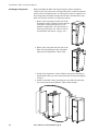
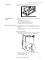
Join the Symmetra
3-Phase UPS enclosure to
the PDU with System
Bypass enclosure
1. Move the Symmetra 3-Phase UPS into position next to the PDU
with System Bypass, aligning the two openings in the lower part of
the adjacent side panels.
2. Level both the PDU with System Bypass and the Symmetra 3-Phase
UPS. For instructions, see “How to level an enclosure” on page 44.
3. Thread the chase nipple (p/n 820-0071), through the opening in the
adjacent side panels of the PDU with System Bypass and the Symmetra 3-Phase UPS.
4. Tighten the lock-nut and the bushing on the chase nipple.
Connection to be
performed by a licensed
electrician only!
Electrical
Hazard
Note
A licensed electrician must connect the PDU with System
Bypass to the main utility power. Procedures requiring a
licensed electrician include:
• connection of main utility conductors
• connection to the input circuit breaker of the PDU
with System Bypass
• connection to a branch circuit
This PDU with System Bypass contains no parts that are
serviceable by general users. Refer all servicing to APC Field
Service Engineers.
User’s Manual—PowerStruXure Type B
33
Installation: PDU with System Bypass
Connect main utility
power
Electrical
Hazard
Ensure that utility power is OFF before beginning
installation.
A licensed electrician must connect the main utility power:
1. Run three-wires with an equipment ground wire and a GEC
(grounding electrode conductor) from the main utility service of the
building to the PDU with System Bypass.
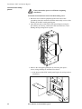
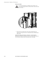
2. Open the back doors of the PDU with System Bypass, using the
provided key for the top, smaller door and loosen the two screws
holding the larger hinge door in place.
3. Remove the rectangular gland plate by loosening the captive
screws, using a Phillips or standard screw driver:
a. in the bottom of the PDU with System Bypass for wiring under a
raised floor.
34
User’s Manual—PowerStruXure Type B
Installation: PDU with System Bypass
b. or in top of the PDU with System Bypass for overhead wiring.
4. Cut an appropriately-sized hole in the gland plate for the conduit.
5. Re-attach the gland plate.
6. Install a lock-nut and bushing to the conduit.
7. Thread the conduit through the hole.
User’s Manual—PowerStruXure Type B
35
Installation: PDU with System Bypass
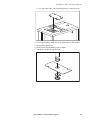
8. Route the input conductors to the main input circuit breaker of the
PDU with System Bypass, as follows:
a. For wiring under a raised floor, run the input conductors through
the wireways A at the right or left side within the PDU with System Bypass to the main input circuit breaker of the PDU with
System Bypass.
b. For overhead wiring, run the cable directly to the main input circuit breaker of the PDU with System Bypass.
36
User’s Manual—PowerStruXure Type B
Installation: PDU with System Bypass
A licensed electrician must connect the input wiring to the PDU with
System Bypass:
9. At the main input circuit breaker, connect the input wiring to the
PDU with System Bypass circuit breaker terminals for phase L1, L2,
and L3, according to the following color-coding:
Input
Voltage
L1
L2
L3
208 V
Black
Red
Blue
480 V
Brown
Orange
Yellow
600 V
Red
Black
Blue
Tighten the lugs on the circuit breaker terminals only to the
torque specified on the circuit breaker’s label.
Warning
10. Connect the equipment ground wire to the lug on the bracket next to
the circuit breaker.
11. Connect the GEC to the second lug on the bracket next to the
breaker and connect to building steel.
User’s Manual—PowerStruXure Type B
37
Symmetra 3-Phase UPS
Only qualified personnel trained by APC may connect the
Symmetra 3-Phase UPS to the PDU with System Bypass.
Warning
Tools required
Tool Required
Position, level, and attach
the Symmetra 3-Phase
UPS
Supplied?
13 mm socket wrench
No
17 mm socket wrench
No
T-20 screwdriver
No
Standard screwdriver
No
Before connecting the Symmetra 3-Phase UPS, you should first position
and level it and then join the Symmetra 3-Phase UPS to the PDU with
System Bypass. See “Exchange side panels” on page 32, “How to level
an enclosure” on page 44, and “Join the Symmetra 3-Phase UPS
enclosure to the PDU with System Bypass enclosure” on page 33.
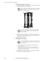
Ensure that all power is
off
Electrical
Hazard
Before electrical installation begins, ensure that power is
off by following the procedure below:
1. Set utility power to the OFF or Locked Out position.
ON
OFF
2. Open the DC breaker and set the System Enable switch on the Symmetra 3-Phase UPS to the Off position.
38
User’s Manual—PowerStruXure Type B
Installation: Symmetra 3-Phase UPS
3. Open the Main input circuit breaker on the PDU with System
Bypass.
4. Open the Q1, Q2, and Q3 breakers on the PDU with System
Bypass.
Perform all power wiring before installing modules into the
Symmetra 3-Phase UPS.
Note
User’s Manual—PowerStruXure Type B
39
Installation: Symmetra 3-Phase UPS
Connect the PDU to the
UPS
Only qualified personnel trained by APC may connect the
Symmetra 3-Phase UPS to the PDU with System Bypass.
Warning
Attach power wiring to and from the Symmetra 3-Phase UPS. The
power wires are coiled in the bottom of the PDU with System Bypass.
Five input wires are at left and four output wires are at the right. Both
sets are labeled with colors: black for L1, red for L2, blue for L3, white
for neutral, and (input only) green for the equipment ground wire.
Refer to the wiring diagram on page 41 as you follow this
procedure:
Note
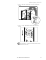
1. Remove the back lower panel of the Symmetra 3-Phase UPS.
2. Use the opening in the side panels of the PDU with System Bypass
and Symmetra 3-Phase UPS to run the wires between the units.
3. Attach the equipment ground wire from the PDU with System
Bypass to the ground stud below the input terminal block at right on
the Symmetra 3-Phase UPS (➌).
4. Attach the neutral wire and the input wires for the phases to the
connectors with the corresponding colors and labels on the input
terminal block at right on the Symmetra 3-Phase UPS (➍).
5. Attach the neutral wire and the output wires for the phases to the
connectors with the corresponding colors and labels on the output
terminal block at left on the Symmetra 3-Phase UPS (➎).
6. Connect EPO control wires from the PDU with System Bypass to
the EPO board on the Symmetra 3-Phase UPS (➏).
7. Connect Maintenance Bypass control wires from PDU with System
Bypass to the Maintenance Bypass interface board (➐) of the Symmetra 3-Phase UPS .
40
User’s Manual—PowerStruXure Type B
Installation: Symmetra 3-Phase UPS
wiring diagram
GEC
G
L1
L2
L3
PDU
UPS
L1 L2 L3 N
L1 L2 L3 N
AC OUTPUT
AC INPUT
EPO / PCB
4
3
2
1
14 13 12 11 10 9
8
8
7
7
6
6
MAINTENANCE BYPASS / PCB
5
5
4
3
2
1
1
2
3
4
5
6
7
8
9 10 11 12 13 14
1
2
3
4
5
6
7
8
9 10 11 12 13 14
User’s Manual—PowerStruXure Type B
41
Emergency Power-Off Switch
Choose a connection
method
Choose only one connection.
Note
Emergency power-off can be achieved with any one of the following
four methods:
• Applying 120 VAC
• Applying 24 VDC
• Applying 24 VAC
• Contact closure
APC recommends contact closure.
EPO User Interface
AC 120V
DC 24V
Contact Closure
.
.
.
AC 24V
Hazardous voltage from the branch circuit must be isolated from the 24
Vac, 24 Vac and contact closure. 24 VAC and 24 VDC are considered a
Class 2 circuit as defined in Article 725 of the National Electrical Code
(NFPA 70) and Section 16 of the Canadian Electrical Code (C22.1).
A class 2 circuit is a source having limited voltage and energy capacity
as follows:
a. If an Inherently Limited Power Source, voltage and energy are
limited to < 30 VAC, < 60 VDC, 8 A.
b. If Not Inherently Limited Power Source, voltage and energy are
limited to < 30 VAC, < 60 VDC, 250 VA, and the current is limited to 1000/Vmax. The fuse is limited to 5 A if < 20 VAC or 20
VDC, or 100/Vmax if < 30 VAC or 60 VDC.
If choosing to use 24 VAC, 24 VDC or contact closure to perform the
EPO function, the wires should be UL Listed, type:
• CL2 Class 2 cable for general purpose use; or
• CL2P Plenum cable for use in ducts, plenums and other space used
for environmental air; or
• CL2R Riser cable for use in a vertical run shaft from floor to floor;
or
• CL2X Limited Use cable for use in dwellings and for use in
raceway.
42
User’s Manual—PowerStruXure Type B
Installation: Emergency Power-Off Switch
• For installation in Canada, the cable should be CSA Certified, type
ELC (extra-low-voltage control cable).
• If CL2 cable is not used, the EPO wiring is to be routed in conduit.
The conduit should not contain any hazardous branch circuit wiring.
Connect a switch to the
EPO interface
1. Connect the switch to the EPO interface mounted on the bottom of
the PDU with System Bypass rear panel. (See “Choose a connection
method” on the previous page for guidance).
The default setting on the EPO interface is for a normally open
switch.
Note
2. If you are attaching a normally closed switch:
a. access the monitoring unit through the back doors of the PDU
with System Bypass. The arrow in the illustration below points
to the PDU with System Bypass monitoring unit.
b. Flip the EPO DIP switch on the PDU monitoring unit to change
the default setting from a normally open to a normally closed
setting.
3. On the PDU monitoring unit, ensure that the TEST/ARM rocker
switch is in the ARM position.
User’s Manual—PowerStruXure Type B
43
NetShelter VX Enclosures
Tools required
Tool Required
Supplied
Standard screwdriver
No
Phillips screwdrivers (various sizes)
No
Metric socket wrench or adjustable openended wrench
No
Metric hex drives
No
5mm allen wrench
Yes
Level
No
Open-ended wrench (13 mm/14 mm, for
adjusting the leveling feet of the enclosure)
Yes
Do not discard the open-ended wrench with the packaging of
the enclosure!
Note
Position the enclosures
Position the first enclosure to the right or left of the PDU with System
Bypass, depending on the location of the Symmetra 3-Phase UPS, and
place each additional enclosure after the first to form a row. After
placing the enclosures in the desired position, level, stabilize (if
necessary), and join enclosures before installing any equipment.
How to level an enclosure
Leveling feet are attached under the enclosure at each corner. The
leveling feet can help provide a stable base if the selected floor space is
uneven, but they are not intended to compensate for a badly sloped
surface. The feet and casters can also be completely removed to allow
the enclosure base to rest directly on the floor.
Leveling procedure.
1. Fit the 14-millimeter end of the open-ended wrench (included) to
the hex nut just above the round pad of the leveling foot. Turn the
wrench clockwise to extend the leveling foot until it makes firm
contact with the floor.
2. Repeat step 2 for each of the remaining leveling feet.
44
User’s Manual—PowerStruXure Type B
Installation: NetShelter VX Enclosures
3. Use a level to determine which feet need further adjustment to level
the enclosure. Adjust as necessary.
Do not move the enclosure after the leveling feet are
lowered—the leveling feet may bend.
Warning
How to stabilize the
enclosure
American Power Conversion offers two additional products for
stabilizing enclosures:
• Stabilizer Plate Kit (AR8115ABLK)—one plate and mounting
hardware for attaching to the enclosure frame. One plate can be
installed in front and two plates can be used on each side. Stabilizer
plates may also be bolted to the floor to add stability.
• Bolt Down Bracket Kit (AR8112BLK)—four brackets and mounting
hardware for attaching to the enclosure frame on the sides (exterior
or interior). These brackets must be anchored to the floor to provide
stabilization.
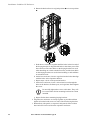
How to join enclosures
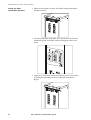
together
You can expand your installation by joining an expansion enclosure to a
base enclosure or two expansion enclosures together. The procedure
involves removing one side panel of the base enclosure and attaching it
to the open side of the expansion enclosure. The expansion enclosure
consists of expansion hardware and vertical baying trim that covers the
gap between the joined enclosures for a finished appearance.
Before joining enclosures. Sometimes you must change enclosure
configurations before joining enclosures together. Often this means
reversing the front door on one of the enclosures or moving the trim
from one side of an enclosure to the other.
Preliminary steps for joining enclosures.
1. Reverse the door, if necessary. (See “How to reverse the door” on
page 135.)
2. Remove the side panel from the existing enclosure or bay if necessary. (See “How to remove and install the side panels” on page
131.)
3. If necessary, move the vertical baying trim from one side of the
expansion enclosure to the other side. (See “How to move the vertical baying trim” on page 141.)
How to join enclosures.
1. Connect the four baying brackets pre-installed on the expansion
enclosure to the base enclosure:
a. Using the 5 mm Allen wrench (included), loosen the socket-head
screw that is holding the baying bracket to the expansion
enclosure.
User’s Manual—PowerStruXure Type B
45
Installation: NetShelter VX Enclosures
b. Rotate the bracket from its original position ➊ to its new position
➋.
c. Push the two enclosures together until the holes in the free end of
the baying bracket are aligned with holes in the frame post of the
base enclosure.The outer holes on the baying brackets are used
when installing on 24-inch raised-floor tiles, and the inner holes
on the baying brackets are used when installing on 600-millimeter raised-floor tile.
d. On the base enclosure, insert a caged nut into the holes that align
with the holes in the expansion bracket.
e. Repeat steps a–d for each expansion bracket.
f. On the base enclosure, insert a socket-head screw through the
holes in the bracket, the frame post, and caged nut. Hand-tighten
the screw.
Note
Do not fully tighten the screws at this time. They will
be secured after all four mounting brackets have been
installed.
g. Repeat for the three remaining baying brackets.
2. Align the two enclosures as closely together as possible and then
tighten all socket-head screws on each of the four baying brackets.
3. Reinstall any side panels, as required. Side panels removed from
base enclosure can be used on the expansion enclosure.
46
User’s Manual—PowerStruXure Type B
Cable Troughs, Partitions, and Ladders
Troughs and partitions for
overhead wiring along
rows
If you ordered APC cable troughs, partitions, and ladders to route
overhead wiring for your PowerStruXure system, you must assemble the
power cable troughs and the data cable partitions along the rows of
enclosures and assemble the ladders between rows.
Power cable troughs. Each power cable trough is two feet in length
and is not adjustable. There are two types of power cable troughs:
A
B
The PDU power cable trough sits atop the PDU with System
Bypass and has an opening in one end to fit around the power
cables where they exit the PDU with System Bypass.
TheNetShelter VX power cable troughs have an opening in each
side through which you can route data cables to the data cable
partitions.
A
B
Data cable partitions. There are two types of data cable partitions,
each of which forms a side wall of a trough for data cables. You can
customize the width of the trough for each row of your system—wider
for rows carrying many data cables, narrower for rows carrying fewer.
A data cable trough for each row must use, as its back wall, a partition
that contains an opening ( C ) for routing data cables.
C
User’s Manual—PowerStruXure Type B
47
Installation: Cable Troughs, Partitions, and Ladders
How to install power
cable troughs
Use the procedure in this section for both the PDU and NetShelter VX
power cable troughs. Make sure you install the PDU power cable trough
on the PDU with System Bypass.
Note
When installing NetShelter VX power cable troughs, be sure
that the opening for routing data cables is facing the front of
the enclosure.
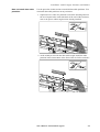
Install power cable troughs along the back edge on the roof of each row
of enclosures. To install:
1. Insert the rear set of fastening tabs into the square holes along the
top back of the unit.
2. Squeeze the sides of the section towards each other at the bottom to
insert the front fastening tabs.
NetShelter VX
PDU with System Bypass
Symmetra 3-Phase UPS
Note
48
When installing the PDU power cable troughs, drape the
power cables (whips) over the UPS as shown. After you have
finished installating the troughs in the row, route the power
cables using the troughs.
User’s Manual—PowerStruXure Type B
Installation: Cable Troughs, Partitions, and Ladders
How to install data cable
partitions
Use the procedure in this section to install all data cable partitions. You
can install data cable partitions on any enclosure.
1. Squeeze the two sides of a partition to insert the fastening tabs into
the set of square holes toward the back of the roof of the enclosure,
next to the power cable trough sections already installed.
2. At the width you need for the data cable trough, install the other
partition in the same manner at the front of the roof of the enclsoure.
User’s Manual—PowerStruXure Type B
49
Installation: Cable Troughs, Partitions, and Ladders
Ladders for overhead
wiring across rows
After installing the power cable troughs and data cable partitions, install
the ladders between rows of enclosures.
Note
If you are installing more than one row of enclosures within
the PowerStruXure system, you must install an overhead
ladder.
Use wide (12-inch) ladders where many power cables or data cables will
run between rows; use narrow (6-inch) ladders where few power cables
or data cables will run between rows (e.g., to rows farthest from the PDU
with System Bypass.)
You can adjust the length of the ladders in the following ways:
• You can cut back the ends to shorten them by using a hacksaw
• You can extend their length several inches by inserting the
connectors only partially into the side rails.
Note
50
Do not change the spacing between rows and the length and
physical positioning of the ladders from the basic layout you
planned with your APC representative when you placed your
order. For overhead wiring, each whip is provided at a predetermined length to reach the enclosure whose devices it will
support. Changes to the physical configuration of your
PowerStruXure system could cause some power cables
(whips) to be too short or too long.
User’s Manual—PowerStruXure Type B
Installation: Cable Troughs, Partitions, and Ladders
How to install ladders
across rows
To install the ladders for typical configurations:
1. On each side rail of the ladders, insert the ladder brackets.
.
2. Attach the ladders to the troughs in one of the three (a–c) following
ways:
A
For two rows of enclosures that face front to front, do one of the
following:
• Use the ladder brackets to attach the 12-inch ladder to the
slotted top of the power cable troughs of adjacent rows. The
ladder runs above the data cable partition to span the rows and
to carry power cables and data cables.
User’s Manual—PowerStruXure Type B
51
Installation: Cable Troughs, Partitions, and Ladders
• Use two ladders, one attached between power cable troughs
to carry power cables, and the other between data cable
partitions to carry data cables.
v
52
User’s Manual—PowerStruXure Type B
Installation: Cable Troughs, Partitions, and Ladders
B
For two rows of enclosures that face back to back attach the
ladders as follows:
• Attach one ladder to the slotted top of the power cable
trough to carry power cables across rows.
• Attach another ladder to the slots low on the side of the
power cable trough at an opening for the data cables. This
ladder will carry data cables after they are routed through the
opening under the power cable trough.
B
C
Alternatively, you can mount the two ladders side by side, using
the slots in the top edge of the power cable trough.
User’s Manual—PowerStruXure Type B
53
Power Cables (Whips)
Route and attach
overhead wiring
If you ordered overhead wiring, connect the prewired power cables of
the PDU with System Bypass as follows:
1. Install the troughs, partitions, and ladders as described in “Cable
Troughs, Partitions, and Ladders” starting on page 47 so that you
can route power cables from the PDU with System Bypass to the
NetShelter VX enclosures.
2. Find the numbers that indicate the enclosure to which each power
cable will supply power. These numbers appear on the roof of the
PDU with System Bypass where the power cables exit, and they
also appear on the ends of each power cable.
Note
The enclosures are not numbered. Consult your APC
PowerStruXure Configuration Buildout Tool to determine
the enclosure associated with each power cable.
3. Beginning with the power cables for the enclosures farthest from
the PDU with System Bypass, run each power cable within the
power cable trough along the row and, if necessary, across one or
more ladders to the enclosure to which it will provide power.
Note
Ensure that the L21-20 twist-lock connector at the end of
each power cable always lies on top of any longer power
cables in the trough.
4. Connect the appropriate power cable to APC power management
equipment in the enclosure in one of the four following ways:
– For single-feed devices without redundancy, attach a power cable
directly to a Metered Rack-Mount PDU installed in a NetShelter
VX enclosure.
– For dual-feed devices within a redundant system, attach a power
cable from each PDU with System Bypass into two different
Metered Rack-Mount PDUs in the NetShelter VX enclosure.
54
User’s Manual—PowerStruXure Type B
Installation: Power Cables (Whips)
– For single-feed devices within a redundant system with an
Automatic Transfer Switch, connect a power cable to the
Automatic Transfer Switch (A and B feeds) and connect the
Automatic Transfer Switch power cord to a Metered Rack-Mount
PDU in the NetShelter VX enclsosure.
– For dual-feed devices in a redundant system with an Automatic
Transfer Switch, connect a power cable from each PDU with
System Bypass to the Automatic Transfer Switch’s A and B
feeds, and another power cable from one PDU with System
Bypass to a Metered Rack-Mount PDU, and the Automatic
Transfer Switch’s power cord to a second Metered Rack-Mount
PDU in the NetShelter VX enclosure.
Note
Lay the cables neatly in the trough to minimize cable
build up. If they are not laid neatly, all the cables will not
fit.
User’s Manual—PowerStruXure Type B
55
Installation: Power Cables (Whips)
5. From each NetShelter VX enclosure, run the power cable of the
appropriate APC power management device out the roof of the
enclosure, through the notch in the rear side of the power cable
trough, to the connector of the appropriate power cable from the
PDU with System Bypass. Plug the two twist-lock connectors
together, and twist them clockwise to lock.
56
User’s Manual—PowerStruXure Type B
Installation: Power Cables (Whips)
Wiring under the floor
Electrical
Hazard
A licensed electrician must route and connect the power
cables for under-floor wiring.
If you plan to route the power cables (whips) to the enclosures under a
raised floor, you must provide the appropriate power cables and
equipment for installation, and a licensed electrician must route and
connect the power cables to the circuit breakers of the PDU with System
Bypass. To wire each cable to an enclosure:
1. Push out a knock-out filler in the floor of the PDU with System
Bypass to create an opening for the cable.
2. Install Liquidtite™ waterproof conduit under the floor from the
enclosure to the PDU with System Bypass.
3. From the Metered Rack-Mount PDU or Automatic Transfer Switch
in the enclosure, thread a four-wire cable with ground from the
enclosure through the Liquidtite conduit to the PDU with System
Bypass.
4. At the PDU with System Bypass, route the four-wire cable with
ground through the opening you created in step 1 and then up
through the wireways at the left or right side within the PDU with
System Bypass. This will allow you to connect the four-wire cable
to the breaker panel.
5. At the breaker panel, cut the wires to the proper length, connecting
the three “hot” wires to a properly sized three-phase circuit breaker
on the PDU with System Bypass.
6. Connect the neutral wire to the neutral bar and the ground wire to
the ground bar.
Electrical
Hazard
Make sure all wire connections and circuit breaker
connections are properly torqued.
User’s Manual—PowerStruXure Type B
57
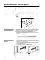
3-Phase Automatic Transfer Switch
Placement
Reserve the top 1U space (for overhead wiring) or bottom 1U space (for
under-floor wiring) in the NetShelter VX enclosures for the Automatic
Transfer Switch.
1. Attach the left and right mounting brackets to the unit, using two
flat-head, Phillips screws (provided) for each bracket.
Attach mounting brackets
Place the brackets flush with the front of the rack to leave
room for routing cables.
Note
.
Disassemble segments of
the adjustable bracket
The adjustable brackets are necessary only if you are using a four-post
enclosure or rack. If you are using a two-post rack, the Automatic
Transfer Switch is supported by the mounting brackets alone.
1. Disassemble each adjustable bracket by removing the slide screw
and nut.
2. Set the screws, nuts, and the adjustable bracket segments aside.
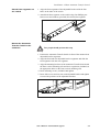
Attach rear segments to
the rack
1. Insert caged nuts (included) on the enclosure’s rear vertical mounting rails at your chosen location.
2. Align the rear segments of the adjustable bracket with the caged
nuts you inserted in Step 1.
3. Insert mounting screws (included) and tighten.
58
User’s Manual—PowerStruXure Type B
Installation: 3-Phase Automatic Transfer Switch
Attach front segments to
the switch
1. Align the front segments of the adjustable bracket with the four
holes on the sides of the switch.
2. Attach both front segments to the switch using four Phillips panhead screws and washers (provided) for each bracket segment.
Mount the Automatic
Transfer Switch in the
enclosure
Two people should perform this step.
Warning
1. Position the Automatic Transfer Switch in front of the mounted rear
adjustable bracket segments.
2. Align the front and rear adjustable bracket segments and slide the
front segments onto the rear segments.
3. Align the mounting brackets of the Automatic Transfer Switch with
the front vertical mounting rails and insert caged nuts (included) in
the appropriate holes on the front vertical mounting rails.
4. Insert mounting screws (included) and tighten.
5. Insert slide screws and nuts into each adjustable bracket and tighten
to secure the positions of the adjustable brackets.
User’s Manual—PowerStruXure Type B
59
Metered Rack-Mount PDU
Mounting options
You can install Metered Rack-Mount PDUs in one of two ways: using
toolless mounting pegs or the mounting brackets. The Metered RackMount PDUs are mounted in the rear of the enclosure, in the channel
directly behind the rear vertical mounting rails. Before you begin to
install the Metered Rack-Mount PDUs, choose a location for them in the
enclosure and decide on the mounting method.
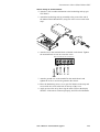
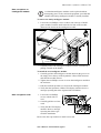
Toolless mounting
1. Slide the mounting pegs into the holes provided in the channel in
the rear panel of the enclosure. Make sure the bottom pegs slide into
the bottom holes in the enclosure.
2. Snap the Metered Rack-Mount PDU into place by pushing it downward until it locks into position.
60
User’s Manual—PowerStruXure Type B
Installation: Metered Rack-Mount PDU
Bracket-mounting
You can attach a pair of brackets to the Metered Rack-Mount PDU in
two different directions, shown in the figures in step 1. Consider the
orientation of the Metered Rack-Mount PDU in the enclosure before
attaching the brackets. A recessed orientation allows the Metered RackMount PDU to be mounted flush with the enclosure; a raised orientation
allows you to route cables through the channel (see the figures in step 2).
1. Attach two brackets to the rear of the Metered Rack-Mount PDU,
using six pan-head screws (provided in the bracket kit) for each
bracket.
– Recessed Orientation
– Raised Orientation
User’s Manual—PowerStruXure Type B
61
Installation: Metered Rack-Mount PDU
2. Insert one mounting screw (provided with the bracket kit) in the top
and bottom positions in the channel where the brackets align with
the holes. Tighten to secure the Metered Rack-Mount PDU to the
enclosure.
– Recessed Orientation
– Raised Orientation
62
User’s Manual—PowerStruXure Type B
Information Controller and Hub
The Information Controller and Hub will come pre-installed in the PDU
with System Bypass. However, if at any time you need to install either or
both of the units into a rack or PDU, follow the procedure in this section.
Attach mounting brackets
to the Controller and Hub
1. Attach the left and right mounting brackets to the controller, using
two flat-head, #2 Phillips screws (provided) for each bracket.
2. Attach the left and right mounting brackets to the hub, using three
flat-head, #1 Phillips screws (provided) for each bracket.
Mount the Controller and
Hub in the PDU with
System Bypass
The top 1U space in the PDU with System Bypass enclosure is reserved
for the Information Controller Hub, and the second 1U space is reserved
for the Information Controller. In the NetShelte VX, use the top two U
spaces for the Information Controller and the Information Controller
Hub. Use the following procedure for installing both components:
1. Insert caged nuts (provided with the enclosure) above and below the
notched holes on the vertical mounting rails, occupying the reserved
1U space for the component you are installing in the enclosure.
2. Plug the component into one of the provided power cords preinstalled in the PDU with System Bypass and slide it into place. If
you are installing the component into a NetShelter VX or a rack, use
the provided power cords.
3. Align the mounting holes on the brackets with the caged nuts you
installed in Step 1, and insert two mounting screws (provided with
the enclosure) to secure the brackets to the enclosure.
User’s Manual—PowerStruXure Type B
63
System Start-Up
Start-Up Procedure . . . . . . . . . . . . . . . . . . . . . . . . . .67
Important safety information 67
Ensure that power is off 67
Apply power to the system 68
Start the UPS using the display interface 71
Verify proper phasing 73
Power the PDU distribution breakers 74
Start-Up Procedure
Important safety
information
Only qualified APC trained personnel may perform a system
start-up.
Warning
Electrical
Hazard
Only those trained in the construction and operation of the
equipment and the electrical and mechanical hazards
involved may install and remove system components.
Ensure that power is off
Electrical
Hazard
Before beginning the start-up procedure, ensure that
power is off by following the procedure below:
1. Open the DC breaker and turn off the System Enable switch on the
Symmetra 3-Phase UPS.
2. Open the Main input circuit breaker on the PDU with System
Bypass.
User’s Manual—PowerStruXure Type B
67
System Start-Up: Start-Up Procedure
3. Open the Q1, Q2, and Q3 breakers on the PDU with System
Bypass.
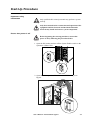
Apply power to the
system
1. Apply utility power to the PDU with System Bypass.
ON
O FF
2. Check the phase rotation at the top of input breaker on the PDU
with System Bypass to ensure that it is A-B-C clockwise rotation,
using a phase rotation meter.
3. Close the main input circuit breaker on the PDU with System
Bypass.
68
User’s Manual—PowerStruXure Type B
System Start-Up: Start-Up Procedure
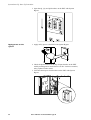
4. Verify that the proper voltage is present at the transformer (208 V,
metered phase-to-phase), using a True RMS voltmeter. Verify the
correct phase rotation at the top of the transformer, to ensure that it
is an A-B-C clockwise rotation, using a phase rotation meter.
Electrical
Hazard
The DC bus in the Symmetra 3-Phase UPS is energized
when battery modules are installed, even when the DC
Disconnect breaker is open.
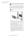
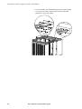
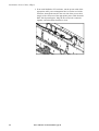
5. Install at least one battery module (4 battery units) in the Symmetra
3-Phase UPS. Install battery units four across, starting in the lowest
available shelf. Position the battery unit to slide in, between the
grooves, and push completely into the enclosure to ensure connection.
4th
3rd
2nd
1st
1st
2nd
3rd
4th
User’s Manual—PowerStruXure Type B
69
System Start-Up: Start-Up Procedure
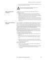
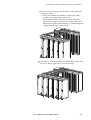
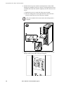
6. Install atleast one power module in the Symmetra 3-Phase UPS.
Install power modules in the top 5 shelves, starting from the lowest
available shelf. Push the module completely into the enclosure and
secure:
a. Tighten the screws on each side of the power module.
b. Turn the locking latch on the right hand side of the enclosure
clockwise until the arrow faces the power module.
The power module will not start unless the locking latch is
engaged.
Note
5th
4th
3rd
2nd
SQy
SQyumickm
-S
um
ic m etatr
k-Se rta T
tatr UseM
rta T r3
U M G-P
se 3 uidh
r G-P ea
uidh se
eas
e
1st
7. Apply AC power to the Symmetra 3-Phase UPS input by closing
the Q1 breaker on the PDU with System Bypass.
70
User’s Manual—PowerStruXure Type B
System Start-Up: Start-Up Procedure
8. Check phase rotation at the Symmetra 3-Phase UPS input terminal
block, ensuring that it is A-B-C clockwise rotation, using a phase
rotation meter.
9. Close the DC breaker and turn on the System Enable switch on the
Symmetra 3-Phase UPS.
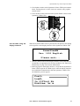
Start the UPS using the
display interface
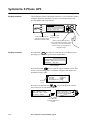
When the System Enable switch is placed in the ON position, the Startup
screen appears on the display interface of the Symmetra 3-Phase UPS.
PowerViewRM
Rev: 0051 English
Please wait...
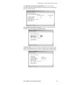
1. Note any alarms listed on the display interface of the UPS and verify that they are appropriate for start-up conditions. See “Basic troubleshooting” on page 118 for more information.
2. Referring again to the display interface, verify that the Symmetra 3Phase UPS accepts the AC Mains input. After the display interface
has established communication with the Symmetra 3-Phase UPS,
the Monitoring screen appears.
Fuel%
Load%
In 000Vout Hz
Runtime: hr m
User’s Manual—PowerStruXure Type B
71
System Start-Up: Start-Up Procedure
Default Monitoring Information
The factory default Monitoring screen displays the following status
information.
Fuel Percentage
The percentage of battery capacity (fuel) that is
available.
Load Percentage
The percentage of system capacity that is being used
to supply conditioned power to the load equipment.
Voltage and Input
Frequency
The input voltage from mains power, the output
voltage supplied to the load equipment, and the
frequency of the input (mains) power.
Run Time
The run-time that can be expected of the batteries.
The intelligence module calculates the run-time
based on both the amount of power required by the
load equipment and the capacity of the battery
modules in the enclosure.
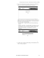
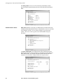
3. Command the UPS to apply power to the load:
a. Press the ESC key at the Monitoring screen to open the Main
menu. This menu allows access to eight submenus:
Control
Status
Setup
Accessories
Logging
Display
Diags
Help
b. Move the selection arrow to the Control item and press the
ENTER key.
c. Move the selection arrow on the Contol menu to the Turn UPS
On item and press the ENTER key.
d. Confirm the selection on the next screen: move the selection
arrow to the Yes, UPS Load ON item and press the ENTER
key. The LOAD ON LED will illuminate and the display will
show the following two screens:
UPS has been
commanded to turn
load power on...
UPS load is on
Press any key...
72
User’s Manual—PowerStruXure Type B
System Start-Up: Start-Up Procedure
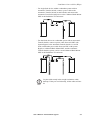
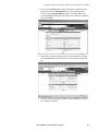
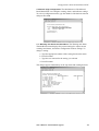
Verify proper phasing
1. Place the Symmetra 3-Phase UPS into Static Bypass mode:
a. Move the selection arrow on the Main menu to the Control item
and press the ENTER key.
Control
Status
Setup
Accessories
Logging
Display
Diags
Help
b. Move the selection arrow on the Contol menu to the UPS into
Bypass item and press the ENTER key.
c. Confirm the selection on the next screen: move the selection
arrow to the Yes, UPS into Bypass item and press the ENTER
key. The BYPASS LED will illuminate and the display will show
the following two screens:
UPS has been
commanded to go
into Bypass...
UPS is in Bypass
Press any key...
2. Check between the Q1 and Q2 breakers that there is no difference in
potential between L1 in and L1 out, L2 in and L2 out, and L3 in and
L3, using a True RMS voltmeter.
User’s Manual—PowerStruXure Type B
73
System Start-Up: Start-Up Procedure
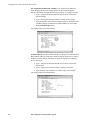
Power the PDU
distribution breakers
1. Make sure all breakers are open on the PDU with System Bypass
distribution panels.
2. Close the Q2 breaker on the PDU. After Q2 has been closed, both
distribution panels on the PDU with System Bypass will be energized.
3. Apply power to the PDU with System Bypass power cords (whips)
by closing the distribution breakers on the PDU with System
Bypass.
74
User’s Manual—PowerStruXure Type B
Communication
Connection
Information Controller and Hub . . . . . . . . . . . . . . . .77
Connect network cables to PowerStruXure
devices 77
Route network cables to the Information Controller
Hub 77
Install and route data cables (alternative routing) 79
Connect the Information Controller and Hub 79
Connect the Information Controller to your LAN 80
Access the APC LAN 80
Configure initial settings on the Information
Controller 82
Assign an IP address to the Information
Controller 84
Verify the address assignment 85
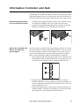
Information Controller and Hub
Connect network cables
to PowerStruXure devices
1. Connect a CAT 5 network cable (provided) to the Network ports on
the Network Management Cards. The following devices have Network Management Cards:
– 3-Phase Automatic Transfer Switch
– Symmetra 3-Phase UPS
– Environmental Monitoring Unit
2. Connect network cables (provided) to the 10Base-T ports on the
Metered Rack-Mount PDU and on the PDU with System Bypass.
Route network cables to
the Information
Controller Hub
Overhead routing.
1. Install troughs and ladders as described in “Cable Troughs, Partitions, and Ladders” on page 47.
2. Run the CAT 5 network cables from each APC device to the Information Controller Hub in the top of the PDU with System Bypass.
a. Run the connected network cable into the data cable trough and
along the row toward the PDU with System Bypass.
b. If necessary to reach the PDU with System Bypass, run the APC
network cables for the entire row, bundled together with cable
ties, across one or more ladders between rows. For the cables to
reach a ladder, you may have to route them through the opening
under the power cable trough for the row.
User’s Manual—PowerStruXure Type B
77
Communication Connection: Information Controller and Hub
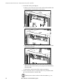
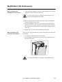
3. At the PDU with System Bypass:
a. Remove one of the two screws in the comb inside the PDU with
System Bypass, and loosen the second screw.
b. Swing the comb outward.
c. Route all the data cables through the opening (under the trough)
and into the enclosure.
d. Press each data cable into a slot in the comb, leaving enough
cable below the comb to allow you to plug it into the Information
Controller Hub.
e. Reinstall the comb into the PDU with System Bypass.
4. Connect each APC device’s network cable to any available station
port in the Information Controller Hub.
Station ports are those with an x after the number (e.g., 2x).
Note
78
User’s Manual—PowerStruXure Type B
Communication Connection: Information Controller and Hub
Install and route data
cables (alternative
routing)
Note
APC strongly recommends routing data cables overhead, as
described in “Overhead routing” on page 77. Using APC data
cable troughs and ladders is the best way to ensure that data
transmission for your PowerStruXure system is free from the
danger of induced voltages.
If you choose to route data cables under a raised floor, note the
following precautions:
• Do not route data cables inside the PDU with System Bypass to the
floor, either within the power cable conduit or in any other location.
Induced voltages from the power cables may interfere with correct
data transmission. You must route data cables out the roof of the
PDU with System Bypass and down inside the first NetShelter VX
enclosure to the floor.
• Induced voltages can also create problems under the floor when
data cables run too close to any power cables. Even if data
transmission is successful after the initial installation, later
additions to power cabling under the floor for other equipment in
your data center can jeopardize the integrity of the data
transmission for your PowerStruXure system.
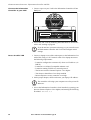
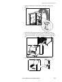
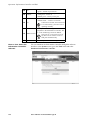
5. Apply power to all devices connected to the Information Controller
Hub.
Note
Ensure that you log the serial number of each APC
PowerStruXure device and where it is installed before
you begin configuring the information controller.
6. After both the Status and Link LEDs on each connected Network
Management Card have turned green, proceed to “Connect the
Information Controller and Hub.”
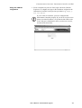
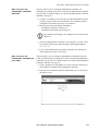
1. Connect the Information Controller’s APC LAN port to any station
port on the Information Controller Hub, using a CAT 5 network
jumper cable (provided)
Connect the Information
Controller and Hub
Station ports are those with an x after the number (e.g., 2x).
.
Note
Inform ation Co ntroller H ub
2X
3X
4X
5X
6X
7X
8X
9X
10X
11X
12X
13X
14X
15X
16X
18X
19X
20X
21X
22X
23X
24X
25X
26X
27X
28X
29X
30X
31X
32X
Col
Uplink
1
2
3
4
5
6
7
8
9
10
11
12
13
14
15
16
17
18
19
20
21
22
23
24
25
26
27
28
29
30
31
32
Pwr
Lin k - R x
Lin k - R x
17X
RS-4 85
RS-2 32
HDD
VGA
CO M 2
CO M 1
Pwr
Moni to r
User’s Manual—PowerStruXure Type B
Link- Rx
Res et
Kb d
APC LAN
32
100
User LAN
Information
Controller
79
Communication Connection: Information Controller and Hub
Connect the Information
Controller to your LAN
1. Connect a port on your LAN to the Information Controller’s User
LAN port.
TO
User LAN
Inform ation Controller H ub
2X
3X
4X
5X
6X
7X
8X
9X
10X
11X
12X
13X
14X
15X
16X
18X
19X
20X
21X
22X
23X
24X
25X
26X
27X
28X
29X
30X
31X
32X
Col
Uplink
1
2
3
4
5
6
7
8
9
10
11
12
13
14
15
16
Pwr
17
18
19
20
21
22
23
24
25
26
27
28
29
30
31
32
Lin k - Rx
Lin k - Rx
17X
RS-4 85
RS-2 32
HDD
VGA
CO M 2
CO M 1
Pwr
Moni to r
Link- Rx
Res et
Kb d
APC LAN
32
100
User LAN
Information
Controller
2. Access the APC LAN by following the instructions in “Access the
APC LAN” starting on page 80.
Note
Access the APC LAN
If you do not have your network set up yet, you can still access
the Information Controller APC LAN and configure initial
settings.
1. Connect a laptop to one of the station ports on the Information Controller Hub, using a CAT 5 network cable. Your laptop must meet
the following requirements:
– It must be configured to automatically obtain an IP address (via
DHCP)
– It must have a 10-BaseT compatible ethernet card
– It must be running TCP/IP as a network protocol
– The browser must be Internet Explorer 5.0 or higher
– Your browser should have Java Script enabled
– Internet Explorer security cannot be set to high
2. On the proper adaptor, release and renew your laptop’s IP address:
The controller will assign your computer one of its private IP
addresses.
Note
3. Access the Information Controller’s local interface by opening your
browser (Internet Explorer 5.0 or higher) and entering the following
IP address: 192.168.1.1
80
User’s Manual—PowerStruXure Type B
Communication Connection: Information Controller and Hub
4. Log on to the Information Controller, using the APC default username (apc, lowercase) and password (apc, lowercase).
When you first log on to the Information Controller, you will see an
initial logon screen. (See the figure below.) To proceed from this
screen, you will need the following:
– The System ID— request from the APC Remote Monitoring
Service
– Number of enclosures—the total number of enclosures in your
PowerStruXure system: XR Frames, Symmetra 3-Phase UPS,
PDU with System Bypass, and NetShelter VX (device)
enclosures
5. Continue with “Configure initial settings on the Information Controller” starting on page 82.
User’s Manual—PowerStruXure Type B
81
Communication Connection: Information Controller and Hub
Configure initial settings
on the Information
Controller
Note
In order to configure the initial settings of the Information
Controller, you will need a list of serial numbers for all APC
devices installed in your PowerStruXure system.
1. Ensure that each installed Automatic Transfer Switch, Symmetra 3Phase UPS, and Environmental Monitoring Unit are listed on the
Information Controller Configure screen by checking your list of
serial numbers with the list of serial numbers on the Configure
screen (see figure below).
2. On the Configure screen, assign each APC device listed to an enclosure.
3. Click on the System button on the Information Controller menu bar
and click on the Inventory tab. On the Inventory screen, enter all
APC device serial numbers that are not detected by the Information
Controller (i.e., NetShelter VX enclosures, PDU with System
Bypass, Metered Rack-Mount PDUs).
82
User’s Manual—PowerStruXure Type B
Communication Connection: Information Controller and Hub
4. Click on the System button on the Information Controller menu
bar and click on the Identification tab. On the Identification
screen, click the Enable RMS check box to enable RMS, and
enter the RMS SMTP mail server address (this address is available
from APC RMS).
5. Change the username and password from the default by clicking
on the System button on the menu bar and clicking on the Users
tab.
6. Continue with “Assign an IP address to the Information Controller” starting on page 84.
User’s Manual—PowerStruXure Type B
83
Communication Connection: Information Controller and Hub
Assign an IP address to the
Information Controller
Assign an IP address to the Information Controller by following the
applicable procedure:
If you are using DHCP on your user LAN... Your IT department
should create a permanent DHCP lease for the IP address assigned to
the Information Controller. You’ll need this IP address to access the
Information Controller from your User LAN.
1. Log off the Information Controller by clicking the Log Off text at
right on the tool bar.
2. Disconnect your laptop from the APC LAN port.
3. Continue with “Verify the address assignment” starting on page
85.
If you are not using DHCP on your user LAN...
How to set a static IP address for the Information Controller:
1. If you are not already connected to the APC LAN, follow the
instructions in “Access the APC LAN” starting on page 80
2. Select the Network tab and disable DHCP on the TCP tab. (See
the figure below.)
3. Provide a User LAN IP Address, Subnet Mask, Default Gateway,
Host Name, Domain Name, Primary DNS Server, and Secondary
DNS Server. (See the figure below.)
All the above items should be provided to you by your IT
department.
Note
4. Log off the Information Controller by clicking the Log Off text at
right on the tool bar.
5. Disconnect your laptop from the APC LAN port.
6. Continue with “Verify the address assignment” starting on page
85.
84
User’s Manual—PowerStruXure Type B
Communication Connection: Information Controller and Hub
Verify the address
assignment
1. From a computer on your user LAN, open a browser (Internet
Explorer 5.0 or higher) and type in the IP address assigned to the
Information Controller in the previous procedure (e.g., http://
192.168.100.2)..
Note
If you see the screen below, you have configured the
Information Controller properly. If you do not see the screen
below, check the IP address, verify that the link LED on the
User LAN port is illuminated, check your browser version,
and check all connections.
User’s Manual—PowerStruXure Type B
85
Configuration
Metered Rack-Mount PDU . . . . . . . . . . . . . . . . . . . . .89
How to configure through a serial port
connection 89
User menus 90
Administrator menus 92
Metered Rack-Mount PDU
How to configure
through a serial port
connection
1. Connect an available serial port on your computer to the serial port
on the front panel of the Metered Rack-Mount PDU, using the supplied configuration cable (p/n 940-0144).
2. Run a terminal emulation software program such as Windows®
HyperTerminal.
3. Configure the appropriate serial port with the following settings:
– 19,200 bps
– no parity
– 8 data bits
– 1 stop bit
– no flow control.
Note
Some terminal emulation software programs require that you
disconnect and reconnect in order for the new serial port
settings to take effect.
4. Press any key on your computer to bring up the Metered RackMount PDU logon menu.
AP7601 Metered Rack-Mount PDU
Username :
Password :
5. Type the default usename and password for the appropriate level of
access:
– Administrator
• Username: type apc
• Password: type apc (lowercase)
– User
• Username: type apc
• Password: press ESC
The Main menu will appear. See “User menus” on page 90 or
“Administrator menus” on page 92 for more information on the menus.
User’s Manual—PowerStruXure Type B
89
Configuration: Metered Rack-Mount PDU
User menus
Main menu. When accessed by a user, the Main menu lists the Status
Information, Configuration, Device Data, and Factory menus. Users can
access—but not configure—data on these menus. To view a menu, type
the associated number and press ENTER.
AP7601 Metered Rack-Mount PDU
Menu Selections
1 - Status Information
2 - Metered Rack-Mount PDU Configuration
3 - Device Data
4 - Factory Data
5 - Logout
System Messages :
Menu Selection >
1: Status Information. The user Status Information menu displays the
present current readings for each phase from the Metered Rack-Mount
PDU and whether the Metered Rack-Mount PDU load has reached or
exceeded the configured limits for output current.
AP7601 Metered Rack-Mount PDU
Status Information
Current (Amps)
-------------Output Current L1 0.0
Output Current L2 0.0
Output Current L3 0.0
Status
-------OK
OK
OK
Menu Selections
<ESC> - Return to Main Menu
System Messages :
Menu Selection >
2: Metered Rack-Mount PDU Configuration. Users can view the
configuration settings for the Metered Rack-Mount PDU. Type 1 and
press ENTER to see the warning and alarm data for current. Type 2 and
press ENTER to see the audio alarm and digital display settings.
AP7601 Rack-Mount PDU
Metered Rack-Mount PDU Configuration
1
- Warning and Alarm Threshold Data
2
- Audio/Visual Indicator Settings
<ESC> - Return to Main Menu
System Messages :
Menu Selection >
90
User’s Manual—PowerStruXure Type B
Configuration: Metered Rack-Mount PDU
2-1: Warning and Alarm Threshold Data. Users can view the
warning and alarm threshold settings for output current. Each setting is
given for all three phases.
AP7601 Rack-Mount PDU
Warning and Alarm Threshold Data
Warning Threshold
----------------L1 Output Current
12
L2 Output Current
12
L3 Output Current
12
Menu Selections
<ESC> - Return to Main Menu
System Messages :
Menu Selection >
Alarm Threshold
--------------17
17
17
2-2: Audio/Visual Indicator Settings. Users can view the present
settings for the audio alarm and digital display.
AP7601 Rack-Mount PDU
Audio/Visual Indicator Settings
Audible Alarm
ENABLED
Display Mode
ENABLED
Display Orientation NORMAL
Menu Selections
<ESC> - Return to Main Menu
System Messages :
Menu Selection >
3: Device Data. Users can view the configured device data about the
Metered Rack-Mount PDU. All data is configured by an administrator.
The device data helps to keep track of the Metered Rack-Mount PDU.
AP7601 Rack-Mount PDU
Device Data
Product Name
Product Location
Contact Information
Log Timeout (mins)
Admin Password
Menu Selections
<ESC> - Return to Main Menu
APC PDU
Enclosure 12
328-223-8976
10
***********
System Messages :
Menu Selection >
User’s Manual—PowerStruXure Type B
91
Configuration: Metered Rack-Mount PDU
4: Factory Data. Users can view the Factory Information, which
provides detailed manufacturing data about the Metered Rack-Mount
PDU.
AP7601 Rack-Mount PDU
Factory Information
Model #
AP7601
Serial #
23458765
Hardware Rev
1.0
Manufacture Date 11/28/2001
Firmware Rev
1.0
Firmware Date
10/22/2001
Menu Selections
<ESC> - Return to Main Menu
System Messages :
Menu Selection >
Administrator menus
Main menu. When accessed by an administrator, the Main menu lists
all Metered Rack-Mount PDU menus. Administrators can access all data
and configure all items. (Users cannot configure any items on the
menus.) To access a menu, type the associated number and press
ENTER.
AP7601 Metered Rack-Mount PDU
Menu
1 2 3 4 5 6 -
Selections
Status Information
Metered Rack-Mount PDU Configuration
Device Data
Factory Data
Logout
System Management
System Messages :
Menu Selection >
1: Status Information. The administrator Status Information menu
displays the present current readings for each phase from the Metered
Rack-Mount PDU, and whether the Metered Rack-Mount PDU has
reached or exceeded the configured limits for output current.
AP7601 Metered Rack-Mount PDU
Status Information
Output Current L1
Output Current L2
Output Current L3
-
Current (Amps)
-------------0.0
0.0
0.0
Menu Selections
<ESC> - Return to Main Menu
System Messages :
Menu Selection >
92
User’s Manual—PowerStruXure Type B
Status
-------OK
OK
OK
Configuration: Metered Rack-Mount PDU
2: Metered Strip Configuration. The administrator of the Metered
Rack-Mount PDU can configure warning, alarm, and indicator settings.
To select a configuration menu, type the number of the desired selection
and press ENTER.
AP7601 Metered Rack-Mount PDU
Metered Rack-Mount PDU Configuration
1
- Warning and Alarm Threshold Data
2
- Audio/Visual Indicator Settings
<ESC> - Return to Main Menu
System Messages :
Menu Selection >
2-1: Warning and Alarm Threshold Data. The Warning and Alarm
Threshold Data menu displays the present settings for output current
warnings and alarms, and allows configuration of those settings. To
change a setting:
a. Type the appropriate number of the setting listed on the menu.
b. Press ENTER..
c. Type the new amount for the setting you selected.
d. Press ENTER.
The change appears immediately in the top alarm and warning data list.
AP7601 Metered Rack-Mount PDU
Warning and Alarm Threshold Data
Warning Threshold
----------------L1 Output Current
-->
12
L2 Output Current
12
L3 Output Current
12
Menu Selections
1
- Next Selection
2
- Enter Warning Threshold
3
- Enter Alarm Threshold
<ESC> - Return to Main Menu
System Messages :
Menu Selection >
User’s Manual—PowerStruXure Type B
Alarm Threshold
--------------17
17
17
93
Configuration: Metered Rack-Mount PDU
2-2: Audio/Visual Indicator Settings. The Audio/Visual Indicator
menu displays the present settings for the audio alarm and digital
display, and allows configuration of those settings. To change a setting:
a. Type 1 and press ENTER until the arrow cursor reaches the
desired setting.
b. Type 2 and press ENTER to make a change to the setting.
c. Type the number of the desired change and press ENTER. (The
available settings and their associated numbers are listed after
the System Messages item.)
The change takes place immediately.
AP7601 Metered Rack-Mount PDU
Audio/Visual Indicator Settings
Audible Alarm
--> ENABLED
Display Mode
ENABLED
Display Orientation NORMAL
Menu Selections
1
- Next Selection
2
- Enable / Normal
3
- Disable / Flipped
<ESC> - Return to Main Menu
System Messages :
Menu Selection >
3: Device Data. The device data can help you keep track of the Metered
Rack-Mount PDU by assigning a unique name for the device, a contact
number or name, and the enclosure in which it is housed. To change a
device data item:
a. Type 1 and press ENTER until the arrow cursor reaches the
desired item.
b. Type 2 and press ENTER to make a change to the item.
c. Type the new value (numbers or letters) and press ENTER.
The change takes place immediately.
AP7601 Metered Rack-Mount PDU
Device Data
Product Name
-->
Product Location
Contact Information
Log Timeout (mins)
10
Admin Password
***********
Menu Selections
1
- Next Selection
2
- Enter Data
<ESC> - Return to Main Menu
System Messages :
Menu Selection >
94
User’s Manual—PowerStruXure Type B
Configuration: Metered Rack-Mount PDU
4: Factory Data. View detailed manufacturing data about the Metered
Rack-Mount PDU.
AP7601 Metered Rack-Mount PDU
Factory Information
Model #
AP7601
Serial #
2332567
Hardware Rev
1.0
Manufacture Date 11/28/2001
Firmware Rev
0.0.7
Firmware Date
10/22/2001
Menu Selections
<ESC> - Return to Main Menu
System Messages :
Menu Selection >
6: System Management. Select the desired item and press ENTER.
Changes take affect immediately. For firmware downloads, follow the
instructions on-screen or see “How to download firmware revisions to
the Metered Rack-Mount PDU” on page 161.
AP7601 Metered Rack-Mount PDU
System Management
1
- Restart RMPDU
2
- Restore Default Parameters & Restart
3
- Firmware Download
<ESC> - Return to Main Menu
User’s Manual—PowerStruXure Type B
95
Operation
System Operation . . . . . . . . . . . . . . . . . . . . . . . . . . .99
How to place the UPS into maintenece bypass operation 99
How to return from maintenance bypass operation
100
Total power off procedure 100
PDU with System Bypass . . . . . . . . . . . . . . . . . . . . .102
Display interface 102
LEDs 102
Top-level status screens 102
Top-level Menu screen 103
Screen map: PDU with System Bypass 105
Load-Meter screen 107
Volt-Meter screen 108
Contacts screen 108
Alarms & Logging screen 109
Config screen 112
Symmetra 3-Phase UPS . . . . . . . . . . . . . . . . . . . . . .116
Display interface 116
Display overview 116
Control functions 117
Status functions 117
Set-up functions 118
Basic troubleshooting 118
General Status troubleshooting 118
Threshold Alarm troubleshooting 119
Bypass troubleshooting 119
General Fault troubleshooting 119
Symmetra 3-Phase UPS display interface menus 120
Operation: Contents
3-Phase Automatic Transfer Switch . . . . . . . . . . . . . 122
Front panel 122
Metered Rack-Mount PDU. . . . . . . . . . . . . . . . . . . . 123
Display interface 123
Alarm conditions 124
Information Controller and Hub . . . . . . . . . . . . . . . 125
Controller front panel 125
Hub front panel 125
How to shut down the Information Controller software 126
How to access the Information Controller APC LAN
127
How to access the Information Controller on your
LAN 127
98
User’s Manual—PowerStruXure Type B
System Operation
How to place the UPS into
maintenece bypass
operation
Place the system into maintenance bypass operation when servicing the
UPS. When in maintenance bypass operation, power flows directly from
the utility to the PDU and out to the load equipment.
1. Command the Symmetra 3-Phase UPS into static bypass through
the Symmetra 3-Phase UPS display interface:
a. Press the ESC key at the Monitoring screen to open the Main
menu. This menu allows access to eight submenus:
Control
Status
Setup
Accessories
Logging
Display
Diags
Help
b. Move the selection arrow to the Control item and press the
ENTER key.
c. Move the selection arrow on the Contol menu to the UPS into
Bypass item and press the ENTER key.
d. Confirm the selection on the next screen: move the selection
arrow to the Yes, UPS into Bypass item and press the ENTER
key. The BYPASS LED will illuminate and the display will show
the following two screens:
UPS has been
commanded to go
into Bypass...
UPS is in Bypass
Press any key...
The H3 LED above the Q3 breaker should illuminate,
indicating that it is safe to operate the Q3 breaker.
Note
2. Close Q3 breaker on the PDU with System Bypass.
The H2 LED above the Q2 breaker should illuminate
indicating that it is safe to operate the Q2 breaker.
Note
3. Open the Q2 breaker on the PDU with System Bypass.
4. Turn the System Enable switch on the Symmetra 3-Phase UPS to
the off position.
User’s Manual—PowerStruXure Type B
99
Operation: System Operation
5. Open the DC Disconnect breaker on the Symmetra 3-Phase UPS.
6. Open the Q1 breaker on the PDU with System Bypass.
Note
How to return from
maintenance bypass
operation
After you have finished these steps you are now in
maintenance bypass operation and you can service the
Symmetra 3-Phase UPS without affecting your connected
equipment.
1. Close the Q1 breaker on the PDU with System Bypass.
2. Close the DC Disconnect breaker on the Symmetra 3-Phase UPS.
3. Turn the System Enable switch on the Symmetra 3-Phase UPS to
the On position.
Note
As soon as you close the DC Disconnect breaker and
turn the System Enable switch to the On position, the
UPS comes up in static Bypass with the load on.
The H2 LED above the Q2 breaker should illuminate
indicating that it is safe to operate the Q2 breaker.
Note
4. Close the Q2 breaker on the PDU with System Bypass.
The H3 LED above the Q3 breaker should illuminate,
indicating that it is safe to operate the Q3 breaker.
Note
5. Open Q3 breaker on the PDU with System Bypass.
As soon as you open the Q3 breaker, the UPS will
automatically come out of Static Bypass.
Note
Total power off procedure
100
1. Open the DC breaker and turn off the System Enable switch on the
Symmetra 3-Phase UPS.
User’s Manual—PowerStruXure Type B
Operation: System Operation
2. Open the Main input circuit breaker on the PDU with System
Bypass.
3. Open the DC Disconnect breaker of each XR Battery Cabinet.
4. Disconnect the batteries in the Symmetra 3-Phase UPS by pulling
them out approximately one inch (25.4 mm) from their normal position.
BATT
ERY
UNIT
5. Set utility power to the Off or Locked Out position.
ON
OFF
User’s Manual—PowerStruXure Type B
101
PDU with System Bypass
Display interface
You can use the display interface of the PDU with System Bypass to
configure settings, set alarm thresholds, and provide audible and visual
alarms.
Liquid crystal
Four LEDs indicate the display (LCD).
operational status of the
PDU with System Bypass.
Select and open menu items,
access information, change system
parameters, and launch contextsensitive help, using the five
navigation keys.
LEDs
LED
Status
The PDU with System Bypass is supplying
conditioned power to the load equipment.
LOAD ON
Green
CHECK LOG
Yellow At least one new alarm condition has been detected.
BYPASS
Power to the load is being supplied directly by the
mains power source. The UPS has been removed
from the circuit for maintenance or replacement.
Yellow
Bypass breakers on the PDU with System Bypass
function as input breakers to protect the load
equipment.
ALARM
Top-level status screens
Color
Red
An alarm condition exists.
After displaying a brief start-up screen after system start-up, the display
interface scrolls automatically and continuously through four screen of
basic status information.
Volts In
Volts Out
L1-2: 112 L1: 112
L2-3: 114 L2: 112
L3-1: 116 L3: 112
Status Screen 1
Total Output Loading
KW: 000.0 PF: 0.00
KVA: 000.0 %LD: 000
Freq: 60.0
Status Screen 3
Load Current
L1: 000
Neut: 000
L2: 001
L3: 000
Gnd: 00.0
Status Screen 2
Active Alarm: 01of11
Input Transformer
Temperature Too High
Status Screen 4
Press the UP and DOWN
keys to interrupt the automatic
scrolling to view a specific status screen.
102
User’s Manual—PowerStruXure Type B
Operation: PDU with System Bypass
Top-level Menu screen
On any top-level status screen, press the ENTER
top-level Menu screen.
Load-Meter
Volt-Meter
Contacts
Breakers
Option
key to open the
Alarms
EPO
Config
Help
Tasks
Load-Meter
Monitor the load that the PDU with System Bypass is
supporting, by phase or in summary.
Volt-Meter
View the input and output voltage data for the PDU with
System Bypass.
Contacts
Configure settings and monitor the present status for any
contacts set up on the PDU with System Bypass
monitoring unit.
Alarms & Logging
Configure alarm settings and view recent and active
alarms.
Config
• Configure setup preferences for your display interface.
• Configure settings for the PDU with System Bypass
and for your network.
• Set the characteristics of the electrical service that
provides input to the PDU.
Help
Obtain help about selected topics and procedures.
Note
If the display interface is inactive for the time specified as the
Time-out setting of the System Password option on the
Config screen, the interface reverts to the initial basic
monitoring screens. See “System Password” on page 112.
arrow keys
To open any screen, press the UP and DOWN
until the selector arrow rests next to your desired selection. Press the
ENTER
key to view the selected screen.
Load-Meter
Volt-Meter
Contacts
Breakers
Alarms
EPO
Config
Help
Contact In: 02of04
Name: User Switch #2
Normal: Open
Status: Open
Top-level Menu screen
Contacts screen
Selector
arrows
When configuring settings, press the UP and DOWN
keys
until the selector arrow rests next to the setting you want to change and
key. If the setting is a list of choices, an input
press the ENTER
arrow will appear next to the setting. Press the UP and DOWN
keys until your desired change is listed. Press the ENTER
key to and change to the setting.
Contact In: 02of04
Name: User Switch #2
Normal: Open
Status: Open
Contacts screen
Input arrow
User’s Manual—PowerStruXure Type B
103
Operation: PDU with System Bypass
On the Config screen and the Breaker screen, continue arrows indicate
that there are additional screens to view in the category. Press the UP
and/or DOWN
keys to view the additional screens.
System/Network
Input Configuration
Panel Configuration
Manufacturer Data
Breaker: 02of05
Name: Q2 Breaker
Normal: Closed
Status: Open
Breaker screen
Config screen
Continue arrows
104
User’s Manual—PowerStruXure Type B
Operation: PDU with System Bypass
Screen map: PDU with
System Bypass
START
Volts
L1-2:
L2-3:
L3-1:
In
112
114
116
Volts Out
L1: 112
L2: 112
L3: 112
Enter
Esc
Load Current
L1: 000
Neut: 000
L2: 001
L3: 000
Gnd: 00.0
Total Output Loading
KW: 000.0 PF: 0.00
KVA: 000.0 %LD: 000
Freq: 60.0
Enter
Esc
Enter
Active Alarm: 01of11
Input Transformer
Temperature Too High
Load-Meter
Volt-Meter
Contacts
Breakers
Load-Meter
Enter
Esc
Alarms
EPO
Config
Help
Contacts
Volt-Meter
Esc
Esc
Esc
Esc
[Future Enhancement]
Total Load
by Phase
Total Load
Summary
KVA
L1: 00.0
L2: 00.0
L3: 00.0
Iout
000
001
000
%LD
000
000
000
Total Output Loading
KW: 000.0 PF: 0.00
KVA: 000.0 %LD: 000
Freq: 60.0
Esc
KW
00.0
00.0
00.0
PF
0.00
0.00
0.00
Output
Voltage
Input
Voltage
Esc
Power
Factor
KVA
L1: 00.0
L2: 00.0
L3: 00.0
Contact In: 01of04
Name: User Switch #1
Normal: Open
Status: Open
Output Voltage
Input Voltage
Total Load by Phase
Total Load Summary
Power Factor
Output Voltage
L1-2: 001
L1: 001
L2-3: 001
L2: 001
L3-1: 001
L3: 001
Input
L1-2:
L2-3:
L3-1:
Voltage
001
001
001
Contact In: 02of04
Name: User Switch #2
Normal: Open
Status: Open
Esc
Esc
The Main Menu is continued on the next page.
Esc
[Up]
[Down]
Contact In: 03of04
Name: User Switch #3 Esc
Normal: Open
Status: Open
Esc
Contact In: 04of04
Name: User Switch #4 Esc
Normal: Open
Status: Open
User’s Manual—PowerStruXure Type B
105
Operation: PDU with System Bypass
Load-Meter
Volt-Meter
Contacts
Breakers
Alarms
EPO
Config
Help
Continuation of Main Menu
Breakers
Alarms
Esc
Breaker: 01of05
Name: Q1 Breaker
Normal: Closed
Status: Open
Breaker: 02of05
Name: Q2 Breaker
Normal: Closed
Status: Open
[Up]
[Down]
Breaker: 03of05
Name: Q3 Breaker
Normal: Closed
Status: Open
View Active
Alarms
Esc
Alarm
Log
Esc
Breaker: 05of05
Name: Q5 Breaker
Normal: Closed
Status: Open
Esc
Alarm
Beeper
Active Alarm: 01of11
Input Transformer
Temperature Too High
Esc
EPO Monitor
State: Disarmed
Switch: Disengaged
View Active Alarms
Alarm Log
Alarm Setup
Alarm Beeper
Alarm
Setup
Breaker: 04of05
Name: Q4 Breaker
Normal: Closed
Status: Open
EPO
Esc
Esc
New Logged Alarms
Esc
Entire Alarm Log
All Possible Alarms
Clear Alarm Log
Esc
Config
Loading Limits
Voltage Limits
Esc
Other Limits
Global Alarm Config
Alarm Beeper(If Active):
--Silence Alarms-All Alarms
Active Alarm
Esc
System/Network
Input Configuration
Panel Configuration
Manufacturer Data
Esc
Product Data
Factory Defaults
Firmware Update
System/
Networks
System Password
Time/Date
Local Interface
Network Address
Esc
Product
Data
Input
Configuration
Service Type: Delta
Input Voltage: 480V Esc
Main Breaker: 200A
Transformer:
YES
Panel
Configuration
Manufacturer
Data
106
Panel Config (Left)
Panel Config (Rght) Esc
Global Panel Config
PDU Monitor
PDU Meter
Esc
User’s Manual—PowerStruXure Type B
Device Name
Product Location
Product Contact
Esc
Factory
Defaults
Set Configuration
to Factory Defaults? Esc
NO, ABORT
YES, Set to Defaults
Firmware
Update
PDU Monitor
PDU Meter
Esc
Operation: PDU with System Bypass
Load-Meter screen
From the Load-Meter screen, you can select the following items:
Total Load by Phase
The load supported by each phase in kVA, in RMS
current (Irms), and as a percentage of the breaker
rating (%LD).
Total Load Summary For the total load supported:
• kW: The power provided, in kilowatts
• kVA: The actual power drawn by the load, in
kilovolt-amperes
• Freq: Frequency
• PF: The power factor, which affects the power
available to the load.
• %LD: The present load as a percentage of the
breaker rating.
Power Factor
For each phase:
• kVA: The actual power drawn by the load, in
kilovolt-amperes (kVA).
• kW: The power, in kilowatts provided by the phase.
• PF: The power factor, which affects the power
available to the load.
Branch Ckt Loading You can display this status if the option to measure
individual currents is installed.
In the Branch Ckt Loading screen, scroll through the
list of breakers in the panel to display the following,
for each pole associated with a breaker:
• Ckt: The panel position of the pole (for example
03).
• nnofbb: The rating in amps (for example 20 A) for
each pole associated with breaker number nn of the
total number of installed breakers bb in the panel
(for example 01of28).
• Irms: the measured root mean square (RMS)
current.
• %LD: Present load as a percentage of rated load.
The following example shows the display for a 3pole, 20-amp breaker. To configure poles so that they
are tied together (i.e., associated with the same
breaker), see “Panel Config (Left)” and “Panel Config
(Right)” on page 114.
User’s Manual—PowerStruXure Type B
107
Operation: PDU with System Bypass
Volt-Meter screen
From the Volt-Meter screen, you can select the following items:
Output Voltage
Displays each phase-to-phase output voltage (e.g. L1-2
for phase L1 to phase L2) and each phase-to-neutral
output voltage (e.g. L1 for phase L1 to neutral).
Input Voltage
Displays each phase-to-phase input voltage (e.g. L1-2 for
phase L1 to L2), and, if your service transformer is a Wye
transformer, each phase-to-neutral input voltage (e.g. L1
for phase L1 to neutral).
Contacts screen
Contact monitoring is a future enhancement that is not available at this
time.
108
User’s Manual—PowerStruXure Type B
Operation: PDU with System Bypass
Alarms & Logging screen
Alarm Beeper. Use this option of the Alarms & Logging screen to
access the following options:
Silence All Alarms Turn off the audible alarm for present and future alarms.
Silence Active
Alarms
Turn off the audible alarm for the present alarm condition
only. If the condition recurs, the alarm sounds again.
If the alarm beeper has been deactivated by previously selecting the
Silence All Alarms option, the Alarm Beeper screen displays the
following option:
Activate Alarm
Beeper
Turns on the audible alarm.
View Active Alarms. Use this option of the Alarms & Logging screen
to display active alarms (alarms that have not been resolved). Scroll
through the list to view each active alarm.
Alarm Log. Use this option of the Alarms & Logging screen to access
the following options:
New Logged
Alarms
Display a description and the date and time of each alarm
that occurred since the last time this option was used.
• The most recent alarm is displayed initially. To move to
the previous alarm, press the DOWN arrow key. To
move to the next more recent alarm, press the UP arrow
key.
• If the log contains no alarms, the screen displays Alarm
Log Empty and the system date and time.
The date/time format is mmm-dd yyyy hh:mm:ss.
Entire Alarm Log Display a description and the date and time of each alarm
in the alarm log.
• The most recent alarm is displayed initially. press the
DOWN arrow key. To move to the next more recent
alarm, press the UP arrow key.
• If the log contains no alarms, the screen displays Alarm
Log Empty and the system date and time.
The date/time format is mmm-dd yyyy hh:mm:ss.
All Possible Alarms Display a description of each alarm that can occur. To
move through the list, press the UP or DOWN arrow key.
For more information on each alarm, see “List of PDU
Alarms” on page 111.
Clear Alarm Log
Delete the contents of the alarm log. This action requires a
password.
User’s Manual—PowerStruXure Type B
109
Operation: PDU with System Bypass
Alarm Setup. Use this option of the Alarms & Logging screen to
access the following options:
110
Loading Limits
(Password required to modify.)
Configure the following, in amps and as a percentage of
full load:
• Out High: The upper limit for output current
• Out Low: The lower limit for output current
• Out Neut: The upper limit for current on the neutral
wire for the output phases
Voltage Limits
(Password required to modify.)
Configure the following, as a percentage under or over the
rated voltage.
• Input: The allowed range for input voltage
• Output: The allowed range for output voltage
Other Limits
(Password required to modify.)
Configure these limits:
• Frequency: The frequency variation, in Hz, that is
acceptable for the output current.
• Gnd Current: The upper limit, in amps, for the current
on the earth ground wire.
• Branch Ckt Limits: Available only if the option to
measure individual currents is installed, Branch Ckt
Limits accesses a scrollable list of the breakers in the
panel. For each breaker, the screen displays, in the
Loading column, the current on each pole as a
percentage of the rated current. In the Load Alarm
column, you can configure the high and low thresholds
for the breaker as a percentage of its rated current. For
example, if you set 80% as the high threshold for a 3pole 20-amp breaker, an alarm condition occurs if the
current on any of the three poles reaches 16 amps.
Global Alarm
Config
(Password required to view or modify.)
Set all the loading limits or all the voltage limits
simultaneously as a percentage of full load:
• Load Limits: Set the same percentage for the upper
limit for output current, the lower limit for output
current, and the upper limit for current on the neutral
wire for the output phases. (Use the Loading Limits
option to set these thresholds individually).
• Volt Limits: Set the same percentage for the high and
low thresholds for input and output voltage. (Use the
Voltage Limits option to set these thresholds
individually).
Select Apply Now and then YES to implement your
changes.
User’s Manual—PowerStruXure Type B
Operation: PDU with System Bypass
List of PDU Alarms. This table lists all alarms that can be generated by the PDU with System Bypass, as
displayed by the All Possible Alarms option, with numeric variables between the < > characters. Logged
alarms will display specific numbers instead.
Alarm Condition
Input V <L-L>=<Value>
Voltage Under Limit
Input V <L-L>=<Value>
Voltage Over Limit
Explanation
Message When
Condition Cleared.
Phase-to-phase input voltage between the
two phases indicated has dropped below the
configured lower limit.
Input Voltage V <L-L>
Back In Range
Phase-to-phase input voltage between the
two phases indicated exceeded the
configured upper limit.
Output V <L-N>=<Value> Phase-to-neutral output voltage for phase
Voltage Under Limit
<L-N> dropped below the configured limit.
Output V <L-N>=<Value> Phase-to-neutral output voltage for phase
Voltage Over Limit
<L-N> exceeded the configured limit.
Output Voltage V <L-N>
Back In Range
Output I <N>=<Value>
Current Over Limit
Current of output phase <N> exceeded the
configured limit.
Output Phase L<n>
Current Under Limit
Current of output phase<N> dropped below
the configured limit.
Output Neutral
Current Over Limit
Current on the neutral wire for the output
phases exceeded the configured limit.
Output Neutral
Current Within Limit
Output FDev=<Value>
Freq Out of Range
Frequency of the output current is above or
below the range that is configured as
acceptable.
Output Frequency
Back In Range
Earth Ground=<Value>
Current Over Limit
Current on the earth ground wire exceeded
the configured limit.
Earth Ground
Current Within Limit
Output Phase <N>
Current Within Limit
BranchBrkr<nn>=<Value> Current on one of the poles of branch circuit
Current Over Limit
breaker nn exceeded the configured limit.
BranchBrkr<nn>
Current on one of the poles of branch circuit Current Within Limit
BranchBrkr<nn>=<Value>
breaker nn dropped below the configured
Current Under Limit
limit.
Input Transformer
Temperature Too High
The temperature of the PDU with System
Bypass transformer exceeded the normal
limit.
Input Transformer
Temp. Back to Normal
Main Circuit Breaker
Open
The Main circuit breaker has been tripped.
Main Circuit Breaker
Has Been Closed
Output Phase L<n>
Fuse Blown
The fuse for output phase Ln has blown.
Output Phase L<n>
Fuse Was Replaced.
System Wrap-Around
Bypass Closed
The bypass breaker has been tripped.
System Returned From
Wrap-Around Bypass.
Alarm Log Cleared
The alarm log has been deleted.
None (not applicable)
User’s Manual—PowerStruXure Type B
111
Operation: PDU with System Bypass
Config screen
System Password. Use this option of the Config screen to access these
options:
Password
Change the system password required to access protected
screens and fields in the display interface. Enter a string of
up to eight alphanumeric characters, followed by the
underline character ( _ ) to indicate the end of the string.
The default password is APC.
Time-out
Set the time that the display interface waits for user input
before it reverts to the initial scrolling of status screens.
Select 1, 2, 5, 10 (the default), or 30 minutes; or 1, 2, or 4
hours, or Forever
Invalidate NOW
Immediately prompts users to re-enter the system
password if they are viewing password-protected screens.
Input Configuration. Use this option of the Config screen to configure
information about the electrical service that provides input to the PDU
with System Bypass.
Service Type
(Requires a password to modify.) The type of transformer
at the service entrance for the building.
112
Input Voltage
The voltage of the service transformer.
Main Breaker
The rating, in amps, of the main breaker for the building’s
electrical service.
Transformer
Whether this PDU has a transformer (YES or NO).
User’s Manual—PowerStruXure Type B
Operation: PDU with System Bypass
Panel Configuration. Use this option of the Config screen to access
these options:
Panel Config (Left) Pos: The pole positions in the left panel, which contains
odd-numbered pole positions only.
Phase: The phase associated with this position.
Breaker: (Requires password to modify.) Two
configurable items:
• The breaker rating, in amps: 20A, 30A, 45A, 50A, or
60A.
• The breaker tie indicator: To be able to monitor breakers
correctly, you define the number of poles tied to (i.e.,
associated with) each breaker. Associating poles with
specific breakers here enables you to use the screen
option “Branch Ckt Loading” on page 107 to scroll, by
breaker number, to information about each breaker.
Also, the alarms “BranchBrkr<nn>=<Value> Current
Over Limit” and “BranchBrkr<nn>=<Value> Current
Under Limit” on page 111 occur for a multi-pole
breaker when any of its poles are above or below the
limit.
To configure the values on this screen:
1. From the first column use the arrow keys to scroll up
or down to the breaker and pole position you want to
configure.
2. Press the ENTER key to move to the item you want to
configure in the third column (the breaker rating or
the breaker tie indicator).
3. Scroll again to select the value you want for the
breaker rating or the breaker tie indicator. To associate the breaker with the next pole position in the list,
choose the + character as the tie indicator immediately following the breaker rating. To indicate that the
breaker is not associated with (tied to) the next pole
position in the list, choose the] character as the tie
indicator immediately following the breaker rating.
When you change the + or] character that follows the
breaker rating in one row, the + or [character before
the breaker rating in the next row also changes to
indicate the changed association between the breaker
and that pole position.
Example: A 1-pole, 30-amp breaker in position 11, and a
2-pole 60-Amp breaker in positions 13 and 15:
User’s Manual—PowerStruXure Type B
113
Operation: PDU with System Bypass
Panel Config
(Right)
Pos: The pole positions in the right panel, which contains
even-numbered pole positions only.
Phase and Breaker. See “Panel Config (Left).”
To scroll the screen and configure values, see “Panel
Config (Left).”
Example: A 3-pole. 20-Amp breaker in positions 8, 10,
and 12.
Global Panel
Config
(Requires password to view or modify.) Configures the
same number of poles and the same breaker rating for all
breakers in both panels simultaneously. For example, if
your system uses only 3-pole, 20 amp breakers, choose
this option, scroll to the value 3 for Poles and 020 for
Amp Rating, and then select Apply Now and YES to
implement your changes.
Local Interface. Use this option of the Config screen to access these
options.
Contract
(Requires password to modify.) Sets the screen contrast
for the LCD. Select from 1 (high contrast) to 8 (low
contrast).
Key Click
On causes an audible click whenever you press a
navigation key. Off disables the key click.
Beeper Volume
Select High, Medium, Low, or Off to adjust the loudness
of the audible beeper and the key click.
Network Interface. Use this option of the Config screen to access
these options to customize system and network settings.
IP
(Requires password to modify.) The System IP address,
which the domain name server translates into a domain
name.
Mask
The subnet mask, which selects some of the bits from an
internet address to route it to the subnet.
MAC
The media access control address, a hardware address that
uniquely identifies the PDU with System Bypass network
node.
Time/Date. Use this option of the Config screen to set any component
of the system time and date. The date format is dd mmm yyyy (for
example, 12 Jun 2001)
To modify values on the Time/Date screen, you must enter the system
password.
Manufacturer Data. Use this option of the Config screen to display a
scrollable list containing information about hardware products in your
PowerStruXure system. For each hardware product, the following data
is displayed.
Manufacturer
Name
114
The company that made the product.
User’s Manual—PowerStruXure Type B
Operation: PDU with System Bypass
Product Contact
The person to notify concerning questions or problems
with regard to the product.
Product Location The physical location of the product in your data center.
Model Number,
Basic information about the product, useful when
Serial Number,
requesting service or product updates.
Product Name,
Hardware
Revision,
Manufacture Date
User’s Manual—PowerStruXure Type B
115
Symmetra 3-Phase UPS
Display interface
The Symmetra 3-Phase UPS display interface is a local interface used to
configure functions, monitor the system, set alarm thresholds, and
provide audible and visual alarms.
LOAD ON
Fuel 100%
Load 000%
120Vin 000Vout 60Hz
Runtime: 00hr 30m
ON BATT
BYPASS
ESC
?
FAULT
Liquid crystal
Four LEDs report the display (LCD).
operational status of the
Symmetra 3-Phase UPS.
Select and open menu items,
access information, change system
parameters, and launch contextsensitive help, using these five
navigation keys.
Display overview
Press the ESC ESC key until you reach the top-level Status screen
providing you with basic system status information.
Fuel 10%
Load 000%
120Vin 000Vout 60Hz
Runtime: 0hr 0m
Top-Level Status Screen
(factory default)
Press the ENTER
key to open the top-level Menu screen. This
screen is the launching pad to command, configure, and monitor the
Symmetra 3-Phase UPS.
Selector
arrow
Control
Status
Setup
Accessories
Logging
Display
Diags
Help
Top-Level Menu
keys to navigate the selector
Press the UP and DOWN
arrow and view all sub menu screens.
Capacity: 12.0kVA
Fault Tolerance: n+2
Total UPS Modules: 03
Bad UPS Modules: 00
Bat Voltage: 128.5V
Bat Capacity 100.0%
Runtime: 01hr 30min
16 Batts, 00Bad
Power Module Status Screen
Battery Module Status Screen
Scroll arrows
indicate additional
screens
116
User’s Manual—PowerStruXure Type B
Operation: Symmetra 3-Phase UPS
Press the UP and DOWN
keys, and the ENTER
key to move the Input arrow to select and enter information.
Low Batt Dur:
2min
20sec
Shutdwn Dly:
Return Dly:
0sec
Return Bat Cap:
0%
Shutdown Menu
Control functions
Low Batt Dur:
10min
Shutdwn Dly:
20sec
Return Dly:
0sec
0%
Return Bat Cap:
Input arrow
Shutdown Menu
To turn the load on/off:
1
Turn Load On
Do Self Test
Simulate Power Fail
Graceful Reboot
2
UPS LOAD IS OFF
Press any key...
Control Menu
Load Off Screen
To place the Symmetra 3-Phase UPS in/out of bypass mode:
1
Graceful Turn Off
Start Runtime Cal
UPS into Bypass
2
UPS IS BYPASSED
Press any key...
Bypassed Screen
Control Submenu
Placing the Symmetra 3-Phase UPS into bypass mode stops
backup protection.
Warning
Status functions
Verify general module status
1
Control
Status
Setup
Accessories
Logging
Display
Diags
Help
2
Capacity: 12.0kVA
Fault Tolerance: n+2
Total UPS Modules: 03
Bad UPS Modules: 00
Status Screen 6
Top-Level Menu
Verify voltage on all phases
1
Control
Status
Setup
Accessories
Logging
Display
Diags
Help
2
Top-Level Menu
Input: 123.3V 59.9Hz
Output: 0.0V
Runtime: 0hr 0min
Load:
A
0%VA
Status Screen 1
Verify battery voltage/capacity
1
Control
Status
Setup
Accessories
Logging
Display
Diags
Help
Top-Level Menu
User’s Manual—PowerStruXure Type B
2
Bat Voltage: 215
Bat Capacity: 10.0%
Self Test: None
Status Screen 5
117
Operation: Symmetra 3-Phase UPS
Set-up functions
The display interface settings are set to factory defaults. For more
information on the settings that you can change, refer to the Symmetra
3-Phase UPS product manual (in PDF) available on the Information
Controller Help page or on our Web site at: www.apc.com/support.
Changing factory default settings
1
Control
Status
Setup
Accessories
2
Logging
Display
Diags
Help
Top-Level Menu
Basic troubleshooting
Settings:
Shutdown
Defaults
Output Freq
Alarms
Bypass
Copy
Other
Settings Menu
This Troubleshooting section will help you solve most problems using
the Symmetra 3-Phase UPS display interface.
Note
If the display interface reports a problem, verify that the
component in question is correctly installed in the Symmetra
3-Phase UPS. If the problem persists, follow the instructions
in “How to Obtain Service” on page 167.
For advanced configuration, refer to the Symmetra 3-Phase UPS Product
Manual on the Information Controller Help page or on our Web site at:
www.apc.com\support.
General Status
troubleshooting
118
Display Message
Meaning
Corrective Action
Input Freq outside
configured range
The input frequency to
the Symmetra 3-Phase
UPS is outside the
configured range. The
output frequency will not
synchronize with the
input frequency. Normal
bypass is not available.
Option 1: Improve the
frequency of the
incoming voltage.
Option 2: Widen the
range of the acceptable
incoming frequency using
the display interface.
(Startup-Setup-Output
Freq Select.)
Option 3: Proceed with
startup—normal bypass is
not available.
AC adequate for
UPS but not for
bypass
The Symmetra 3-Phase
UPS will function online with the input
voltage, but in the event
that bypass is required,
the input voltage is not
adequate to power the
load equipment.
Option 1: Improve the
incoming voltage.
Option 2: Proceed with
startup—normal bypass is
not available.
User’s Manual—PowerStruXure Type B
Operation: Symmetra 3-Phase UPS
Threshold Alarm
troubleshooting
Display Message
Meaning
Corrective Action
Redundancy has
been lost
The Symmetra 3-Phase
UPS no longer detects
redundant power
modules. Either a power
module(s) has failed, or
the load has increased.
Option 1: If possible,
install additional power
modules.
Option 2: Decrease the
load
Option 3: Disable the
redundancy alarm by
setting redundancy to
zero. (Startup-SetupAlarms-Redundancyselect zero)
Runtime is below
alarm threshold
The predicted runtime is
lower than the userspecified minimum
runtime alarm threshold.
Either the battery
capacity has decreased,
or the load has increased.
Option 1: Allow the
battery modules to
recharge.
Option 2: If possible,
increase the number of
battery modules.
Option 3: Decrease the
load.
Option 4: Use the
display to decrease the
minimum runtime alarm
threshold (Startup-SetupAlarms-Runtime-select).
Meaning
Corrective Action
Bypass troubleshooting
Display Message
Bypass is not in
range (either freq
or voltage)
General Fault
troubleshooting
The frequency and/or
voltage is out of
acceptable range for
bypass. This message
occurs when the
Symmetra 3-Phase UPS
is online, and indicates
that the bypass mode
may not be available if
required.
Option 1: Decrease the
sensitivity to input frequency. (Startup-SetupOutputFreq-select).
Option 2: Correct input
voltage to provide
acceptable voltage and/or
frequency.
Meaning
Corrective Action
Need Bat
Replacement
One or more battery units
need to be replaced.
Refer to “How to replace
a battery unit” on page
158 for more
information.
The Redundant
Intelligence
Module is in
control
The main intelligence
module has failed, and
the redundant
intelligence module is
functioning as the
primary intelligence
module.
Replace the main
intelligence module. See
“How to replace an
intelligence module” on
page 159 for more
information.
Display Message
User’s Manual—PowerStruXure Type B
119
Operation: Symmetra 3-Phase UPS
Symmetra 3-Phase UPS
display interface menus
The following two figures show the display interface menus and the
navigation path to each menu.
START
Fuel 100%
Load 100%
208Vin 208Vout 60Hz
Runtime: 0hr 30min
Any Key
Esc
Control
Status
Setup
Accessories
Control
Status
Esc
Turn Load ON/Off
Do Self Test
Simulate Power Fail
Graceful Reboot
Graceful Turn Off
Start Runtime Cal
UPS Into Bypass
Turn Load
ON/OFF
Confirm:
Turn Load ON
NO, ABORT
YES, Turn Load ON
Logging
Display
Diag
Help
Vin
1 209.0
2 208.0
3 209.0
Esc
Setup
Vout
208.0
208.0
208.0
Iout
Esc
20A
22A
20A
% load assuming no
redundancy:
50%
Simulate
Power Fail
Shutdown
UPS Into/
Out of Bypass
% load allowing for
n+x redundancy:
50%
Frequencies
Input: 60.01Hz
Output: 60.00Hz
Confirm:
Esc
Graceful Reboot
NO, ABORT
YES,Graceful Reboot
Confirm:
Graceful Off
NO, ABORT
YES, Graceful Off
Esc
[Down]
Confirm:
Esc
Start Runtime Cal
NO, ABORT
YES, Do Runtime Cal
Esc
Esc
Esc
Output
Freq
Output Freq Range:
60Hz + 0.1Hz
Esc
Alarm Thresholds
Redundancy: 1
Load:
10.0kVA
Runtime:
0hr 15m
Esc
Esc
Alarms
Batt Voltage:211.5V
Batt Capacity:100.0% Esc
Runtime: 0hr 30min
16 Batts, 0 Bad
Bypass
Capacity: 40.0 kVA
Fault tolerance: n+2 Esc
Total Pwr Modules:05
Bad Pwr Modules: 0
Copy
If UPS fails, and
line freq or voltage
is out of normal
range: Go To Bypass
[Up]
Copy UPS Settings
Configuration 1
From UPS to Display
From Display to UPS
Esc
Esc
Other
Confirm:
UPS Into Bypass
Esc
NO, ABORT
YES,UPS Into Bypass
Alarm Thresholds
Fault Tolerance: n+1 Esc
Runtime: 0hr 15min
Load: 10.0 kVA
Self Test: Ok
Last Xfer: None
Status: On Line
IM: OK
RIM: OK
120
Low Batt Dur: 2min
Shutdown Dly: 20sec
Return Dly:
0sec
Return Batt Cap:15%
Set all UPS settings
to Factory Defaults?
NO, ABORT
YES,Set to Defaults
Esc
Graceful
Turn Off
Start/Stop
Runtime Cal
Alarms
Bypass
Copy
Other
Defaults
Confirm:
Do Self Test
NO, ABORT
YES, Do Self Test
Confirm:
Simulate Power Fail Esc
NO, ABORT
YES, Simul Pwr Fail
Graceful
Reboot
Settings:
Shutdown
Defaults
Output Feq
Esc
Do Self Test
Esc
Esc
User’s Manual—PowerStruXure Type B
Self Test: 14 days
UPS ID: UPS_IDEN
VoutReporting: AUTO
Output: 208V
BatFrAmpHour:1000
Esc
Operation: Symmetra 3-Phase UPS
START
Fuel 100%
Load 100%
208Vin 208Vout 60Hz
Runtime: 0hr 30min
Any Key
Esc
Control
Status
Setup
Accessories
Accessories
Logging
Display
Diag
Help
Display
Logging
Esc
Esc
Diag
Esc
Esc
Accessories
View Log Clear Log
View Statistics
Configure Logging
List Event Groups
MeasureUPS
Network Card
Measure
UPS
Network
Card
MeasureUPS
Probe 1 Stat Setup
Probe 2 Stat Setup
Zones
Status
Esc
7-Aug 01:23:34 #64
Zone 4 OK
Probe 1 Temp OK
Comm Established
View Log
View
Statistics
Network Card
Network Setup
View Network Setup
Esc
Date/Time
Beeper
Password
Contrast
Information Config
Esc
Date:
Time:
Aug 7 2001
15: 30
Esc
Frame
Status
Password
1 Transfers->Bat
0 Low Bats
3 Faults
0Hr 0Min On Bat
Esc
Information
Power Events: On
UPS Control: On
UPS Faults: On
User Activity: On
Measure UPS: On
Power Events
UPS Control Events
User Activities
UPS Fault Events
Measure UPS Events
Esc
Beeper
Password:»********
('_'= end)
Timeout: Èmin
Invalidate NOW
Esc
Model# APC9999
Esc
S/N: A94063038681
Manuf Date: 11/18/94
Revs:HW=C3
FW=A3a
------- Beep ------At UPS: PwrFail+30s Esc
At Disp: LowBatt
Vol:»Low Click: On
Esc
Clear Event
Log
Contrast
Confirm:
Clear Event Log
NO, ABORT
YES, Clear Log
Fault &
Diagnostics
An Installed UPS
Module has failed
Esc
More
Configure
Logging
List Event
Groups
Date/Time
Fault & Diagnostics
Frame Status
Ext Device Status
Comm Bus Status
Esc
Contrast:2
Ext Device
Status
Main Frame of 5
Status:14 of 16 bats Esc
Sub-Systems
Raw Status Data
Maintenance Bypass
Esc
Battery Breaker Box^
Comm Bus
Status
Ext. Iso Transformer^
Bus, Int
Ext
MIM: XXXXXX XXXXXX Esc
RIM: XXXXXX XXXXXX
MIM<->RIM: XXXXXX
Esc
Config
»Fuel 100% ²²²²²²²²
»Load 100% ²²²²²²²²² Esc
Ð8Vin 230Vout 60Hz
»Runtime: 002hr 20min
User’s Manual—PowerStruXure Type B
121
3-Phase Automatic Transfer Switch
Front panel
3Ø Automatic
Transfer Switch
No.
122
Item
Description/Function
Reset switch
Resets the Network Management Card to its default settings. This
switch does not affect the settings of the Automatic Transfer
Switch.
Ethernet Port
Connects the Automatic Transfer Switch to the Information
Controller Hub, using an APC network cable (provided).
Rx-Link LED
Indicates whether there is activity on the network.
Status LED
Indicates whether the Network Management Card is powered on.
Preference Selection
button
Sets which power source will be the preferred source to supply
power to the load equipment. In normal operation, if both sources
are available, the Automatic Transfer Switch will use the preferred
source. Press the Preference Selection button to change the
preferred source.
Preference A and B
LEDs
Indicate which of the two sources (if any) is selected as the user’s
preferred source. Both LEDs off means that neither source is
preferred.
Provide information about the condition of the input voltages from
both sources. If a source is considered OK, the corresponding
indicator will light. A source is OK if the RMS input voltage on all
Source A and B LEDs three phases and the measured frequency are within the selected
tolerance ranges.
In a normal operating condition (full source redundancy), both
LEDs are illuminated.
Connector LEDs
Indicates which source is being used for the output. Only one
arrow will be lit at any time. The combination of Source LEDs,
Connector LEDs, and Output LEDs provide a graphical view of the
power flow though the Automatic Transfer Switch.
Output indicator
Shows that voltage is truly available at the output for the
Automatic Transfer Switch.
Configuration port
The local connection for accessing all the setup, status,
maintenance and diagnostic information for the Automatic
Transfer Switch.
User’s Manual—PowerStruXure Type B
Metered Rack-Mount PDU
Display interface
➊
12
➐
➏
➋
➌
➎
➍
➊ Control button
• press to change the phase of the current displayed on the
digital display
• press and hold for five seconds to view the orientation;
hold for an additional five seconds to change the
orientation
• press to silence an alarm
➋ Digital display†
• shows the current for the phase corresponding to the
Phase Indicator LED that is illuminated
• cycles through all three phases in 3-second intervals
➌ Serial port
• access internal menus by connecting this port (RJ-11
modular port) to a serial port on your computer, using the
supplied serial cable (p/n 940-0144)
➍ Phase indicator LEDs
• indicates the phase corresponding to the current listed in
the digital display
• indicates normal (green), warning (yellow) or alarm (red)
condition
➎ Status LED
• reserved for future use
➏ Ethernet port
• reserved for future use
➐ Link LED
• reserved for future use
†Each Metered Rack-Mount PDU is equipped with a sensor that measures the current
being used by the Metered Rack-Mount PDU and devices connected to it. The value
displayed is the aggregate current of an individual phase.This value is used to generate alarms that you define. For information on configuring alarms, see “2-1:
Warning and Alarm Threshold Data” on page 93.
User’s Manual—PowerStruXure Type B
123
Operation: Metered Rack-Mount PDU
Alarm conditions
The warning and alarm limits are configurable through the internal
menus through a serial port connection. For instructions on accessing the
internal menus, see “How to configure through a serial port connection”
on page 89. The following table describes warning and alarm conditions.
Behaviors During Alarm Condition
Phase Indicator LED
Yellow: warning
Red: alarm
Digital Display
Control Button
Shows the current • Causes the digital display to
for the phase at or
show the current reading for the
above the warning
next phase
or alarm limit.
• After 30 seconds of disuse, the
display will return to the phase
(or cycle among phases) at or
above the warning or alarm
limit.
Do not exceed the maximum voltage and current ratings listed
on the rear panel of the Metered Rack-Mount PDU.
Warning
124
User’s Manual—PowerStruXure Type B
Information Controller and Hub
Controller front panel
➌
➏
RS-485
RS-232
HDD
VGA
COM 2
COM 1
Pwr
Monitor
11
1
Link-Rx
Reset
➊
10
➋ ➍ ➎
Kbd
Information
Controller
User LAN
APC LAN
➐ ➑
100
9
➊
COM 2
RS-485 port—reserved for future use.
➋
COM 1
RS-232 port—reserved for future use.
➌
HDD
Hard disk drive LED:
• amber—disk is being accessed
➍
Power
Power LED:
• green—the controller is powered on
➎
VGA/Monitor Connector—reserved for future use.
➏
Reset
Switch that reboots the Information Controller.
The controller is shipped with a plastic screw
inserted into the reset switch.
➐
Kbd
PS/2 Keyboard port—reserved for future use.
➑
APC LAN
9
User LAN
Ethernet port used to connect to the user’s
network.
Link-Rx
Link LEDs:
• solid amber—link is valid
• flashing amber—activity on the port
• off—link is invalid
10
Ethernet port for connecting to the private
APC network.
Speed LEDs:
• off—operating at 10 Mbps
• green—operating at 100 Mbps
100
11
Because the APC LAN operates at
10Mbps, it is normal for the APC LAN
speed LED to be off .
Hub front panel
Information Controller Hub
2X
3X
4X
5X
6X
7X
8X
9X
10X
11X
12X
13X
14X
15X
16X
18X
19X
20X
21X
22X
23X
24X
25X
26X
27X
28X
29X
30X
31X
32X
Col
1
2
3
4
5
6
7
8
9
10
11
12
13
14
15
16
17
18
19
20
21
22
23
24
25
26
27
28
29
30
31
32
Lin k - Rx
Pwr
Lin k - Rx
17X
32
User’s Manual—PowerStruXure Type B
125
Operation: Information Controller and Hub
Power LED:
• green—the hub is powered on
➊ Pwr
➋ Link-Rx
LEDs indicate status for each port:
• solid green—link is on
• flashes green—activity on the port
Collision LED:
• flashes amber—collision on network
➌ Col
➍
Collisions are normal; unless this LED
is on continuously, your APC LAN is
operating normally.
Station ports for connecting PowerStruXure
equipment to the Information Controller. The
“x” in the numbering is short for MDI-X.
10Base-T Ports
Only port 32 or 32x can be in use at
any time. Do not connect covers to
both parts simultaneously.
➎ Uplink Port
10Base-T port for interconnecting hubs.
How to shut down the
Information Controller
software
You can shutdown the Information Controller through the software
interface: at the System screen, go to the Tools menu and select
Shutdown Information Controller.
126
User’s Manual—PowerStruXure Type B
Operation: Information Controller and Hub
How to access the
Information Controller
APC LAN
This procedure is for accessing the Information Controller; for
information on setting up the APC LAN and the Information Controller
on your LAN, see the procedures in “Connect the Information Controller
and Hub” on page 79.
1. Connect a computer to one of the ports on the Information Controller Hub, using a 10Base-T network cable. This computer must be
configured to automatically obtain an IP address.
2. Release and renew your laptop’s IP address:
– for Windows 95/98 run winipcfg.exe
– for Windows NT/2000, run ipconfig.exe
The controller will assign your computer one of its private IP
addresses.
Note
3. Access the Information Controller’s local interface (via APC LAN)
by opening your browser and entering the following IP address:
192.168.1.1
4. Log on to the Information Controller, using the APC default username and password (apc, lowercase).
How to access the
Information Controller on
your LAN
This procedure is for accessing the Information Controller from your
LAN; for information on setting up the APC LAN and the Information
Controller on your LAN, see the procedures in “Connect the Information
Controller and Hub” on page 79.
1. From a computer on your public LAN, open a browser and type in
the IP address assigned to the Information Controller.
2. Enter the APC default username and password (apc, lowercase) on
the logon screen.
User’s Manual—PowerStruXure Type B
127
Customization
NetShelter VX Enclosures . . . . . . . . . . . . . . . . . . . .131
How to remove the leveling feet and casters 131
How to remove and install the side panels 131
How to identify one U-space on the mounting
rail 133
Caged nuts 133
How to install and remove caged nuts 133
Grounding studs 134
Location of cable access holes 134
Skirt removal 135
Cable management devices 135
How to reverse the door 135
Mounting rails 139
Location of screws for adjusting the mounting
rail 139
How to adjust the mounting rails on the frame
posts 139
How to move the rails to a new position using the
side braces 139
How to move a brace 140
How to remove the roof 140
How to move the vertical baying trim 141
Metered Rack-Mount PDU . . . . . . . . . . . . . . . . . . . .142
Hardwiring procedure (optional) 142
NetShelter VX Enclosures
How to remove the
leveling feet and casters
1. Gently place the enclosure on its side. This should be done with all
equipment removed from the enclosure.
To avoid personal injury or damage to the enclosure, two
people should support the enclosure.
Heavy
2. Remove the four hex nuts from each caster, using a 10-millimeter
wrench, and remove the casters.
3. Fit the 14-millimeter end of the open-ended wrench (included) to
the hex nut just above the round pad on the bottom of the leveling
foot. Turn the wrench clockwise to extend the leveling foot until it
comes off.
4. Repeat Step 3 for each of the remaining leveling feet.
How to remove and
install the side panels
You can remove the side panels for access to the interior. To remove the
side panels:
1. Use the key to unlock the panel, if necessary.
2. Slide both panel latches down at the same time and pull the top of
the panel toward you.
To avoid personal injury, two people should lift the panel.
Heavy
User’s Manual—PowerStruXure Type B
131
Customization: NetShelter VX Enclosures
3. Release the latches and lift the panel up and off the narrow horizontal lip at the bottom of the enclosure frame.
To reinstall: Engage the bottom of the panel securely with the rail before
pushing the top of the panel forward into place.
132
User’s Manual—PowerStruXure Type B
Customization: NetShelter VX Enclosures
How to identify one
U-space on the mounting
rail
When installing equipment, you will need to locate the top and bottom
of a U-space on the mounting rails. Every third mounting hole on the
mounting rails of a NetShelter VX enclosure is notched and numbered
to indicate the middle of a U-space. A U-space takes up one of these
notched holes and one hole immediately above and below it, as shown.
31
One
U
30
29
Caged nuts
During installation of equipment in your enclosure, you may need to
install or remove caged nuts. Follow the procedures in this section when
installing or removing caged nuts from the enclosure.
Warning
How to install and
remove caged nuts
Install caged nuts horizontally, with the ears engaging the
sides of the mounting hole. Do NOT install caged nuts
vertically with the ears engaging the top and bottom of the
mounting hole.
Install the caged nuts on the side of the mounting rail that is
opposite the equipment to be mounted.
Note
1. Insert the caged nut into the mounting hole by hooking one ear of
the caged nut assembly through the far side of the hole.
2. Place the caged nut tool (included) on the other ear of the caged nut
and pull to snap it into position.
3. Detach the tool from the caged nut.
To remove: Remove any attached screws and reverse the action in Step
2. Grasp the caged nut before releasing the tool.
User’s Manual—PowerStruXure Type B
133
Customization: NetShelter VX Enclosures
Grounding studs
The enclosure has thirteen grounding studs, which are located on the
doors, the roof, the side panels and the frame. American Power
Conversion offers an optional grounding kit (AR8390) for grounding the
enclosure.
Ground Studs
Qty
Location of cable access
holes
Location
4
Base
1
Rear cabling channel
1
Roof
2
Front door
4
Rear doors
1
Side panels (base model only)
There are cable access holes in the roof ➊, sides ➋, and base ➌ of the
enclosure. The rear cabling channel on the back of the enclosure has
ample clearance between the doors and the mounting rails for cable
routing.
134
User’s Manual—PowerStruXure Type B
Customization: NetShelter VX Enclosures
Skirt removal
The skirt at the front of the enclosure can be detached for additional
cable access by removing the screws.
Cable management
devices
Optional cable management devices can be used for helping to route and
dress cables:
• Cable Management Hoops (AR8113)
• Cable Containment Kit (AR8116BLK)
• Rear Cable Management Tray (AR8118BLK)
• Side Cable Management Tray (AR8114BLK)
How to reverse the door
You can reverse or remove the front door to accommodate your site
configuration. This section shows how to remove and reverse the door
on your enclosure.
1. Remove both side panels. (See “How to remove and install the side
panels” on page 131.)
Reverse the door handle.
2. Remove the two Phillips screws from the rear of the door handle
assembly and remove the handle assembly from the door.
3. Rotate the door handle assembly 180° and reinstall it using the
hardware removed in Step 2.
4. Continue with “Remove the door” on page 136.
User’s Manual—PowerStruXure Type B
135
Customization: NetShelter VX Enclosures
Remove the door.
Warning
To avoid personal injury or damage to the enclosure, one
person should support the door while another releases the door
from its frame.
5. Open the door and pull down on the spring-loaded hinge pin
attached to the top of the door. Lift the door from its frame and set
safely aside.
Remove the hinge pin brackets, bumpers, and latch plates.
Remember the location and distance between all items being removed.
You will need to duplicate this positioning when reinstalling.
136
User’s Manual—PowerStruXure Type B
Customization: NetShelter VX Enclosures
6. Use a Phillips head screwdriver to remove the hinge pin brackets,
bumpers, and latch plate from the enclosure frame.
On the expansion enclosure, the bumpers and latch plate screws
also attach the finishing trim. Replace the trim using the sockethead screws. Replace the bumpers and latch plate using the countersunk screws from the hardware bag.
Reinstall the hinge pin brackets.
7. Reinstall the hinge pin brackets on the opposite side of the enclosure:
a. Remove the small plastic plugs covering the insertion holes in
the plinths and the top of the enclosure frame.
b. Reinstall the two hinge pin brackets from their original position
➊ to their new position ➋.
c. Secure the hinge pin brackets by threading the hex nuts onto the
screws. Hand-tighten the screws; they will be tightened firmly
later in the procedure.
User’s Manual—PowerStruXure Type B
137
Customization: NetShelter VX Enclosures
Reinstall the latch plate and bumpers.
8. Reinstall the latch plate and the two door bumpers from their original position ➊ to their new position ➋.
Note
Be sure to maintain the original spacing between the latch
plate and bumpers, as well as their vertical relationship
with the enclosure frame.
Note
If you are using an expansion enclosure, use the sockethead screws in the hardware bag to reinstall the latch
plate and bumpers.
9. Reinstall the small plastic plugs in the frame and the plinths in the
empty holes that once held the hinge pin brackets and hinge pins
before the door was reversed.
Reinstall the door assembly.
10. Reinstall the door assembly.
Warning
To avoid personal injury or damage to the enclosure, one
person should support the door while another secures the
door to its frame.
a. Reverse the steps for removing the door. (See “Remove the
door” on page 136.)
b. Make sure that the door opens and closes properly and then
firmly tighten the countersunk screws to secure the hinge pin
brackets to the enclosure frame.
11. Reinstall the side panels for AR2100 series. (See “How to remove
and install the side panels” on page 131.)
138
User’s Manual—PowerStruXure Type B
Customization: NetShelter VX Enclosures
Mounting rails
The vertical mounting rails are factory-installed in the proper position
for use with Compaq® rack-mountable equipment that has a depth of
29.13 inches (739 mm). You can adjust the rails to the front or rear a
total of 2.35 inches (60 mm) to accommodate different rails or
equipment with various depths. You can also move the rails by attaching
them to the horizontal braces. The following sections describe the
procedures for adjusting the position of the mounting rails and for
moving them within the enclosure.
Location of screws for
adjusting the mounting
rail
The location of the screws that govern the position of the mounting rails
is shown below.
2.35”
(60 mm)
How to adjust the
mounting rails on the
frame posts
1. Use the 5-millimeter Allen wrench (included) to loosen (but not
remove) the socket-head screws in the slot of the mounting rail.
How to move the rails to
a new position using the
side braces
1. Remove the side panels from the enclosure. (See “How to remove
and install the side panels” on page 131.)
2. Slide the mounting rail forward or rearward as desired, staying parallel with the frame posts. Tighten each screw.
2. Use the 5-millimeter Allen wrench (included) to remove the sockethead screws in the slots of the mounting rail.
3. Locate the new position for the mounting rail.
4. Secure the vertical mounting rail to each horizontal brace:
Note
You may have to adjust the position of the brace up or
down to align it with the mounting channel in the rear
mounting rail. (See “How to move a brace” on page 140.)
a. Insert a caged nut into the appropriate holes at the new position
on the upper and lower horizontal brace.
b. Place the mounting rail at the new position and insert a sockethead screw through the rail, brace, and caged nut.
c. Tighten the screw to secure the mounting rail to the brace.
User’s Manual—PowerStruXure Type B
139
Customization: NetShelter VX Enclosures
How to move a brace
Each side of the enclosure has two horizontal braces between the
vertical frame posts. These adjustable braces provide structural support
and are available for managing cables or to support the mounting rails.
1. Use the 5mm Allen wrench (included) to remove the four sockethead screws that are holding the brace to the frame posts.
2. Remove the caged nuts from the frame post. (See “How to install
and remove caged nuts” on page 133.)
3. Locate the new position for the brace and secure the brace to the
frame posts:
a. Insert a caged nut into the appropriate holes at the new position
on the frame post.
b. Place the brace at the new position and insert a socket-head
screw through the brace, frame post, and caged nut.
c. Tighten the screw to secure the brace to the frame post.
How to remove the roof
Remove the roof from the enclosure by removing the four socket-head
screws from the inside corners. Use the 5-millimeter Allen wrench
(included).
140
User’s Manual—PowerStruXure Type B
Customization: NetShelter VX Enclosures
How to move the vertical
baying trim
The vertical baying trim is pre-installed to one side of the expansion
enclosure. The vertical baying trim ➊ covers the gap between enclosures
after they have been joined together. Your site configuration may require
you to move the trim to the other side of the enclosure.
1. Using the 5-millimeter Allen wrench (included), remove the four
socket-head screws securing the vertical trim, the door latch, and
the door bumpers to the frame of the enclosure.
2. Replace the door latch and bumpers using the countersunk sockethead screws from the hardware bag.
3. Reinstall the trim to the opposite side of the enclosure.
a. Insert the capped socket-head screw, removed from the other
side of the enclosure, through the upper hole in the vertical trim
and the original hole in the frame of the enclosure.
b. Repeat the step above for the lower hole in the vertical trim.
c. Tighten the screws securing the vertical trim to the enclosure
assembly.
4. Reinstall any side panels required. (See “How to remove and install
the side panels” on page 131.)
5. Reinstall the roof of the enclosure. Replace the four socket-head
screws with the 5-millimeter Allen wrench (included).
User’s Manual—PowerStruXure Type B
141
Metered Rack-Mount PDU
Hardwiring procedure
(optional)
Remove the power Cord.
Note
Make sure that power to the Metered Rack-Mount PDU has
been turned off and unplug any attached equipment to prevent
damage if a mistake occurs during wiring.
1. Detach the inspection cover on the power inlet end of the Metered
Rack-Mount PDU by removing the four screws on the sides of the
cover and tilt the cover upward so that the terminal block is
exposed. Set the screws aside for later use.
2. Loosen the four screws that hold the power cord’s wires to the terminal block, and loosen the screw that holds the ground wire to the
standoff on the metal chassis.
3. Pull the power cord and the inspection cover from the Metered
Rack-Mount PDU.
142
User’s Manual—PowerStruXure Type B
Customization: Metered Rack-Mount PDU
Attach wiring to terminal block.
4. Attach a 1-inch conduit termination to the hardwiring end cap (p/n
870-70803).
5. Attach the hardwiring end cap assembly to the power inlet end of
the Metered Rack-Mount PDU, using two of the screws removed in
step 1.
6. Attach wires to the terminal block as labeled on the board. Tighten
the terminal block screws to secure the wires.
Metered Rack-Mount PDU Terminal Block
L3
L2
L1
L3
L2
L1
7. Attach a ground wire to the standoff on the metal chassis and
tighten the screw to secure the ground to the chassis.
8. Place the hardwiring access cover (p/n 870-70804) on the strip and
secure with one screw in the hole on the top of the cover.
9. Apply power to the strip, observing the status LED on the display
interface. If the unit is connected properly, the LED will illuminate.
User’s Manual—PowerStruXure Type B
143
Specifications
PDU with System Bypass . . . . . . . . . . . . . . . . . . . . .147
Operating specifications 147
Electrical specifications 147
Symmetra 3-Phase UPS . . . . . . . . . . . . . . . . . . . . . .148
3-Phase Automatic Transfer Switch . . . . . . . . . . . . .150
Metered Rack-Mount PDU . . . . . . . . . . . . . . . . . . . .151
AP7601/AP7602 151
Information Controller and Hub . . . . . . . . . . . . . . .152
Information Controller specifications 152
Information Controller Hub specifications 152
PDU with System Bypass
Operating specifications
Power Distribution Unit
Operating Environment
Protected from water and conductive
contaminates
Temperature Class
Class H (220° C)
Storage Elevation (for aircraft
transportation)
10 000 m
Relative Humidity (for operating
and storage)
95% non-condensing
Operating Temperature
0 – 40° C (32 – 104° F)
Acoustic Noise Emission
Maximum 50dB(A) at 1 m
Electrical specifications
208V
480V
600V
Service Distribution Breaker
(provided by customer)
200 amp
Conductors to Main Input
Breaker (provided by
customer)
3/0 conductors #3 conductors
#4
conductors
Transformer Type
Isolation
Step-Down
Step-Down
Transformer Configuration
Delta to WYE
Delta to WYE
Delta to
WYE
Nominal Voltage
Requirements
208V: 208/
120V
480V: 208/
120V
600V: 208/
120V
Frequency
57 – 63 Hz
57 – 63 Hz
57 – 63 Hz
Input Voltage AC
3-phase 33-phase 3-wire 3-phase 3-wire
wire plus
plus ground,
plus ground,
ground,
480V
208V
600V
Output Voltage AC
3-phase 43-phase 4-wire 3-phase 4-wire
wire plus
plus ground,
plus ground,
ground,
208V
208V
208V
Full Load Output Rating
40 KW
40 KW
40 KW
Maximum Continuous Input
Current (at minimum mains)
155 amps
67 amps
54 amps
Maximum Continuous
Output Current + 125%
Overload (Bypass Mode
only)
139 amps
139 amps
139 amps
Nominal Output Current
111 amps
111 amps
111 amps
Nominal Input Current
125 amps
54 amps
43 amps
Internal Static Switch Fuses
175 amps
175 amps
175 amps
External Output Breaker
150 amps
150 amps
150 amps
User’s Manual—PowerStruXure Type B
100 A
80 amp
147
Symmetra 3-Phase UPS
Symmetra 3-Phase UPS Specifications
Input Specifications
The UPS will operate from mains at full load over the
following ranges: 166 - 240 VAC line-to-line (for North
America); 304 - 477 VAC line-to-line (for Europe) and 160
- 230 VAC line-to-line for Japan (including transformer). If
the AC input voltage exceeds this range, the UPS will
AC Input Voltage operate from battery power. The UPS may operate on-line
below this range if the load is reduced from full power, thus
extending the life of the batteries. When operating on
battery power, the UPS will not retransfer to AC power
until the line has returned to an acceptable level plus a
hysteresis margin (based on loading on the UPS).
DC Input Voltage
The battery voltage produced by the battery system is +/192 VDC nominal
Input Frequency
Range
40-70 Hz.
Input Power
Factor
>0.99 at full load and operating on-line at nominal input
voltage.
Input Inrush
Current
< normal input current without transformer*
Input Generator
Sizing
Generator kW rating > 1.25 x UPS kW rating
Generator kVA rating > 1.40 x UPS kVA rating
Output Specifications
Output Voltage
3x208VAC for North America and Japan
3x380/400/415 VAC for Europe
Output Power
se electrical installation
Load Power
Factor
0.5 - 1.0
Synchronized to mains: programmable frequency range
Output Frequency + 3Hz or
+ 0.1 Hz. around nominal frequency (50 or 60 Hz).
Output Voltage
Regulation Steady + 1%
State
Output Voltage
Regulation
Transient/
Dynamic
+ 5%
Recovery Time
< 5 mS
Total Harmonic
Distortion
<2% when loaded to 100% of rated capacity in Watts
<5% with a computer load under all rated environmental
conditions
Output Specifications
148
Crest Factor
2.7
Overload
Capacity
Sustainable Overload 2: <=150% for 30 seconds
User’s Manual—PowerStruXure Type B
Specifications: Symmetra 3-Phase UPS
Symmetra 3-Phase UPS Specifications
Efficiency, Fully
Charged
>91.5% for North America
Physical Specifications
Audible Noise - at
<58 dBA
70% Load
Dimensions
Width: 23.5” Depth: 34.3” Height: 81.4” (597 x 871 x 2058
mm) for Europe and North America
Width: 47” Depth: 34.3” Height: 2068” (1194x871x2058)
for Japan
Weight - Fully
Loaded
1395 lbs (633 kg) for Europe and North America
2055 lbs (932 kg) for Japan (Isolation Transformer
included)
Heat Dissipation 12,682 BTU/hr (North America)
Fully Loaded
Compliance Specifications
UL Listed
UL 1778
Standards EN50091-2 (Uninterruptible Power Systems,
Part 2: EMC Requirements), EN 55022 (Limits and
methosd of measurement of radio disturbance
CE Verified Class
characteristics of information technology equipment) and
A
EN 50082-1 (Electromagnetic Compatibility - General
Immunity Standard Part 1: Residential, Commercial and
Light Industry).
*< 10 x normal input current with isolation transformer (optional equipment).
User’s Manual—PowerStruXure Type B
149
3-Phase Automatic Transfer Switch
Item
150
Specification
Nominal input voltage
100/173–120/208 V
Acceptable input voltage
90/156–140/242 V
Nominal input frequency
50/60 Hz
Input connectors
Two 36-inch, attached L21-20P line
cords
Output connectors
One 36-inch, attached L21-20R line
cord
Maximum total current draw
16 A per phase
Size (h × w × d)
1.71 × 17.00 × 12.00 in
(4.34 × 43.18 × 30.48 cm)
Weight:
15.00 lb (6.8 kg)
Shipping Weight
20.5 lb (9.30 kg)
Elevation (above MSL):
Operating
0 to 10,000 ft (0 to 3000 m)
Elevation: Storage
0 to 50,000 ft (0 to 15,000 m)
Temperature: Operating
32–104° F (0–40° C)
Temperature: Storage:
32–113° F (0–45° C)
Operating Humidity
0–95%, non-condensing
EMC Verification
FCC Class A, DoC Class A, VCCI
Safety Verification
UL, cUL (UL 60950)
User’s Manual—PowerStruXure Type B
Metered Rack-Mount PDU
AP7601/AP7602
Electrical Specifications
Input
100–120/173–208 V, 3φ 16 A
7601: NEMA L21-20 plug
7602: NEMA L21-20 plug
Output
7601: 100–120 V, 3 × 16 A
42, NEMA 5-20 R receptacles
7602: 100–120/173–208 V, 3 × 16A
21, NEMA 5-20R; 6, NEMA L6-20R receptacles
Physical Specifications
Dimensions
1.75 × 3.5 × 60 in (4.5 × 8.9 × 152.4 cm)
Weight
17 lb (7.7 kg)
Shipping
dimensions
4 × 5 × 72 in (10.2 × 12.7 × 182.9 cm)
Shipping weight
19 lb (8.6 kg)
Operating
temperature
23–113° F (-5– 45° C)
Operating humidity 5–95% RH non-condensing
Operating elevation 10,000 ft (3000 m) above MSL
Storage
temperature
-13–149° F (-25–65° C)
Storage humidity
5–95% RH non-condensing
Compliance Specifications
Approvals
UL, CUL, FCC, VCCI
User’s Manual—PowerStruXure Type B
151
Information Controller and Hub
Information Controller
specifications
Electrical Specifications
Input
100–240 VAC; 50/60 Hz; 0.5 A
Physical Specifications
Dimensions
1.7 ×17 ×6.5 in (4.3 × 43.2 × 16.5 cm)
Weight
6.2 lb (2.8 kg)
Shipping dimensions
2.75 ×18.75 ×13.5 in (7.0 × 47.7 × 34.3 cm)
Shipping weight
8.0 lb (3.65 kg)
Operating temperature
23–113°F (-5–45°C)
Operating humidity
5–95% RH non-condensing
Operating elevation
10,000 ft (3000 m) above MSL
Storage temperature
-13–49°F (-25–65°C)
Storage humidity
5–95% RH non-condensing
Compliance Specifications
Approvals
Information Controller
Hub specifications
UL, cUL, VDE, FCC Class A, AS/NZS 3548,
VCCI Class A, EN 55024, EN61000-3-2,
EN61000-3-3, CE
Electrical Specifications
Input
100–240 VAC; 50/60 Hz; 0.5 A
Physical Specifications
Dimensions
1.7 ×17.0 ×7.0 in (4.3 × 43.2 × 17.8 cm)
Weight
4.8 lb (2.2 kg)
Shipping dimensions
3.25 ×19.25 ×10.5 in (8.3 × 48.9 × 26.7 cm)
Shipping weight
6.5 lb (3.0 kg)
Operating temperature
23–113°F (-5– 45°C)
Operating humidity
5–95% RH non-condensing
Operating elevation
10,000 ft (3000 m) above MSL
Storage temperature
-13–149°F (-25–65°C)
Storage humidity
5–95% RH non-condensing
Compliance Specifications
Approvals
152
UL, cUL, VDE, FCC Class A, VCCI Class
A, EN55022, EN 50082-1, AS/NZS 3548
User’s Manual—PowerStruXure Type B
Maintenance
Symmetra 3-Phase UPS . . . . . . . . . . . . . . . . . . . . . .155
Handling and transport 155
Module replacement 155
How to obtain replacement modules 155
How to replace a power module 156
How to replace a battery unit 158
How to replace an intelligence module 159
How to replace cards 159
Replacement parts 160
How to return modules to APC 160
Metered Rack-Mount PDU . . . . . . . . . . . . . . . . . . . .161
How to download firmware revisions to the Metered
Rack-Mount PDU 161
Symmetra 3-Phase UPS
Handling and transport
Follow these guidelines if you need to ship the Symmetra 3-Phase UPS
to another location.
Electrical
Hazard
Always REMOVE BATTERIES before shipping the
Symmetra 3-Phase UPS to avoid damage during
transport. (U.S. Federal Regulation requires that batteries
be disconnected during shipment.)
The above requirement applies anytime the Symmetra 3-Phase UPS
is moved—either indoors or outdoors, by itself or as part of a
PowerStruXure installation.
Remember to reinstall the battery and power modules after the
Symmetra 3-Phase UPS has arrived at its destination.
Module replacement
Battery units, power modules, and intelligence modules can be replaced
by the user. If a power or a main intelligence module fails and a
“redundant” module is present, the failed module can be replaced
without interrupting power to the load equipment.
If a functioning intelligence module is already installed, you
can replace a redundant intelligence module without interrupting the power to the load.
Note
How to obtain
replacement modules
If the Symmetra 3-Phase UPS is not in the on-battery operating mode, you can replace a battery module without
interrupting power to the load.
To obtain a replacement module, contact APC Customer Support (see
page 168). Prepare to provide the additional information:
• In the event of a module failure, the display interface may display
additional “fault list” screens. Press any key to scroll through these
fault lists, record the information, and relay it to the APC Customer
Support technician.
• If possible, call APC Customer Support from a telephone that is
within reach of the Symmetra 3-Phase UPS display interface. This
will help to gather and report additional information to the APC
Customer Support technician.
• Be prepared to provide a detailed description of the problem. A
Customer Support technician will help you solve the problem over
the telephone, if possible, or will give you a return material
authorization (RMA) number. If a module is returned to APC, this
RMA number must be clearly printed on the outside of the package.
• If the Symmetra 3-Phase UPS is within the warranty period, repairs
will be performed free of charge. (See “Warranty” on page 165.) If
it is not within the warranty period, there will be a charge for repair.
• If the Symmetra 3-Phase UPS is covered by an APC PowerPlanSM
service product, have that information available and give it to the
APC Customer Support technician.
User’s Manual—PowerStruXure Type B
155
Maintenance: Symmetra 3-Phase UPS
How to replace a power
module
Only qualified, APC trained personnel should replace power
modules.
Warning
The display interface indicates the location of the faulty power module
(rows 1 through 5).
To remove the faulty power module:
1. To deactivate the power module, turn the knob (with arrow pointing
toward the module) counterclockwise until it points downward.
2. Turn the spring-activated finger screws (one at either side of the
module) until they pop out.
3. Standing on either side of the Symmetra 3-Phase UPS enclosure,
two people should pull the power module outward until it is fully
extended in the locked position.
4. With the power module resting in the UPS enclosure, release the
lock by depressing the catch on each side of the power module.
5. Pull the power module away from the UPS enclosure.
156
User’s Manual—PowerStruXure Type B
Maintenance: Symmetra 3-Phase UPS
To install the new power module:
1. With one person on each side of the power module, push the power
module all the way into the Symmetra 3-Phase UPS enclosure. (The
power module is self-guiding.)
2. Turn the finger screws clockwise to fasten.
3. Turn the knob clockwise until the arrow points toward the power
module to re-activate the power module.
4. Verify that the Symmetra 3-Phase UPS display interface shows a
message saying that it has registered the installation.
Note
If your Symmetra 3-Phase UPS includes a “redundant” power
module, the failed module can be replaced without
interrupting power to the connected equipment.
User’s Manual—PowerStruXure Type B
157
Maintenance: Symmetra 3-Phase UPS
How to replace a battery
unit
Only qualified, APC-trained personnel should replace battery
units.
Warning
The Symmetra 3-Phase UPS display interface will indicate the location
of the faulty battery unit (rows 1 through 4).
To remove the faulty battery unit:
1. Holding the handle, gently lift the battery handle and then pull it
outward until it is fully extended in the locked position.
2. To release it from the lock mechanism, gently push the battery
upward again and pull outward, supporting the battery unit with
your free hand.
To install a new battery unit:
1. Position the battery to slide in between the two grooves in the
empty slot in the enclosure and push the unit all the way into the
Symmetra 3-Phase UPS enclosure.
2. Check that the Symmetra 3-Phase UPS display interface shows a
message saying that it has registered the installation.
Warning
Install battery units into the enclosure only when you are
ready to apply power to the Symmetra 3-Phase UPS. Failure
to do so can result in a deep discharge of the batteries, which
may cause permanent damage.
Store the battery module(s) in a cool ambient temperature below 77° F
(25° C).
Note
158
Verify that the Symmetra 3-Phase UPS is operating in on-line
mode before replacing a battery module. If the unit is
operating in the on-battery mode, power to the connected
equipment may be interrupted while the battery is being
replaced.
User’s Manual—PowerStruXure Type B
Maintenance: Symmetra 3-Phase UPS
How to replace an
intelligence module
Note
A redundant intelligence module can be replaced without
interrupting power to the connected equipment, provided that
another functioning intelligence module is already installed.
To remove the faulty intelligence module:
1. Loosen the two Phillips screws at either side at the top of intelligence module. Push the small tab in the left side of the module
downward to deactivate the intelligence module.
2. Carefully remove the intelligence module from the enclosure by
pulling outward on the handle.
To install the new intelligence module:
1. Carefully position the intelligence module between the grooves in
the empty slot at the top of the Symmetra 3-Phase UPS enclosure
and slide the module inward.
2. Tighten the two Phillips screws to secure the intelligence module to
the enclosure.
3. Push the small tab upward to re-activate the intelligence module.
4. Verify that the Symmetra 3-Phase UPS display interface shows a
message reporting that it has registered the installation.
How to replace cards
1. Loosen the two Phillips
screws at both sides of
card.
2. Carefully pull the card outward.
3. Verify that the UPS display
interface shows a message
reporting that it has registered the installation.
Reverse the above procedures to install a new card.
User’s Manual—PowerStruXure Type B
159
Maintenance: Symmetra 3-Phase UPS
Replacement parts
Replacement Parts and Numbers
How to return modules to
APC
10kW Power Module
SYPM10KF
40kW Symmetra 3-Phase UPS Only
SYCF40KF
Battery Module
SYBT4
Battery Monitoring Card
SYCBTMON
Battery Unit
SYBTU1
Display and Computer Interface Card
SYCDCI
Intelligence Module
SYMIM4
Network Management Card
AP9616
Switch Gear Monitoring Card
SYCSGMON
Symmetra 3-Phase UPS Static Switch Module
SYSSW40KF
System ID Card
SYCSYSID
System Power Supply Card
SYCSPS
XR Communication Card
SYCXRCOM
XR Frame only
SYCFXR8
Call APC Customer Support (see “APC Worldwide Customer Support”
on page 168) to obtain an RMA number. To return a failed module to
APC, pack the module in the original shipping materials, and return it by
insured, prepaid carrier. The APC Customer Support technician will
provide the address. If you no longer have the original shipping
materials, ask the technician about obtaining a new set. It is very
important that you pack the module properly to avoid damage in transit.
Never use stryrofoam beads or other loose packaging materials when
shipping a module. The module may settle in transit and become
damaged. Enclose a letter in the package with your name, RMA number,
address, a copy of the sales receipt, description of the problem, a phone
number, and a check (if necessary).
Damages sustained in transit are not covered under warranty.
Note
160
User’s Manual—PowerStruXure Type B
Metered Rack-Mount PDU
How to download
firmware revisions to the
Metered Rack-Mount PDU
During firmware downloads, power will not be interrupted to
the Metered Rack-Mount PDU outlets.
Note
1. Go to the APC Web site and download the latest firmware version
for the Metered Rack-Mount PDU.
2. Access the Metered Rack-Mount PDU internal menus: follow the
instructions in “How to configure through a serial port connection”
on page 89.
3. Log on to the Metered Rack-Mount PDU as an Administrator.
4. From the Main menu, type 6 and press ENTER to choose the System
Management item.
5. From the System Management menu, type 3 and press ENTER to
choose the Firmware Download item. From the Firmware Download menu:
a. Type 1 and press ENTER to initiate a download. The internal
menu will dispay C repeatedly and the digital display dL.
b. Select the Transfer pull-down menu from the menu bar.
c. Select Send File from the Transfer pull-down menu.
d. In the Send File window, browse for and select the firmware file
you copied to your hard drive.
e. In the Send File window, set the protocol to Xmodem and press
the Send button.
When the firmware download is complete, the digital dispaly will
refresh and display the current reading again.
User’s Manual—PowerStruXure Type B
161
Product
Information
Warranty . . . . . . . . . . . . . . . . . . . . . . . . . . . . . . . .165
Limited Warranty 165
Life-Support Policy . . . . . . . . . . . . . . . . . . . . . . . . .166
General policy 166
Examples of life-support devices 166
How to Obtain Service . . . . . . . . . . . . . . . . . . . . . .167
If problems persist 167
How to Contact APC . . . . . . . . . . . . . . . . . . . . . . . .168
APC Worldwide Customer Support 168
Document Information . . . . . . . . . . . . . . . . . . . . . .169
Copyright 169
Revision 169
Warranty
Limited Warranty
American Power Conversion (APC) warrants its products to be free
from defects in materials and workmanship for a period of two years
from the date of purchase, except in India where the period is one year
for battery modules. Its obligation under this warranty is limited to
repairing or replacing, at its own sole option, any such defective
products. To obtain service under warranty you must obtain a returned
material authorization (RMA) number from APC Customer Support
(See “How to Obtain Service” on page 167.) Products must be returned
with transportation charges prepaid and must be accompanied by a brief
description of the problem encountered and proof of date and place of
purchase. This warranty does not apply to equipment which has been
damaged by accident, negligence, or misapplication or has been altered
or modified in any way. This warranty applies only to the original
purchaser who must have properly registered the product within 10 days
of purchase.
EXCEPT AS PROVIDED HEREIN, AMERICAN POWER
CONVERSION MAKES NO WARRANTIES, EXPRESSED OR
IMPLIED, INCLUDING WARRANTIES OF MERCHANTABILITY
AND FITNESS FOR A PARTICULAR PURPOSE. Some states do not
permit limitation or exclusion of implied warranties; therefore, the
aforesaid limitation(s) or exclusion(s) may not apply to the purchaser.
EXCEPT AS PROVIDED ABOVE, IN NO EVENT WILL APC BE
LIABLE FOR DIRECT, INDIRECT, SPECIAL, INCIDENTAL, OR
CONSEQUENTIAL DAMAGES ARISING OUT OF THE USE OF
THIS PRODUCT, EVEN IF ADVISED OF THE POSSIBILITY OF
SUCH DAMAGE. Specifically, APC is not liable for any costs, such as
lost profits or revenue, loss of equipment, loss of use of equipment, loss
of software, loss of data, costs of substitutes, claims by third parties, or
otherwise. This warranty gives you specific legal rights and you may
also have other rights which vary from state to state.
User’s Manual—PowerStruXure Type B
165
Life-Support Policy
General policy
American Power Conversion (APC) does not recommend the use of any
of its products in the following situations:
• In life-support applications where failure or malfunction of the APC
product can be reasonably expected to cause failure of the lifesupport device or to affect significantly its safety or effectiveness.
• In direct patient care.
APC will not knowingly sell its products for use in such applications
unless it receives in writing assurances satisfactory to APC that (a) the
risks of injury or damage have been minimized, (b) the customer
assumes all such risks, and (c) the liability of American Power
Conversion is adequately protected under the circumstances.
Examples of life-support
devices
The term life-support device includes but is not limited to neonatal
oxygen analyzers, nerve stimulators (whether used for anesthesia, pain
relief, or other purposes), autotransfusion devices, blood pumps,
defibrillators, arrhythmia detectors and alarms, pacemakers,
hemodialysis systems, peritoneal dialysis systems, neonatal ventilator
incubators, ventilators (for adults and infants), anesthesia ventilators,
infusion pumps, and any other devices designated as “critical” by the
U.S. FDA.
Hospital-grade wiring devices and leakage current protection may be
ordered as options on many APC UPS systems. APC does not claim that
units with this modifications are certified or listed as hospital-grade by
APC or any other organization. Therefore these units do not meet the
requirements for use in direct patient care.
166
User’s Manual—PowerStruXure Type B
How to Obtain Service
If problems persist
If the equipment requires service do not return it to the dealer! Follow
the steps below:
1. Review the appropriate sections of this manual to troubleshoot
common problems.
2. Verify that no circuit breakers have been tripped. A tripped circuit
breaker is the most common UPS problem!
3. If the problem persists, contact APC Customer Support by referring
to “How to Contact APC” on page 168.
4. Note the model number of the product, the serial number, and the
date purchased. A technician will ask you to describe the problem
and try to solve it over the phone, if possible. If this is not possible
the technician will issue a returned material authorization (RMA)
number.
Note
If the equipment is under warranty, repairs are free. If not,
there is a repair charge. Warranty information appears on
page 165.
5. Pack the equipment in its original packaging. If the original packing
is not available, ask Customer Service about obtaining a new set.
6. For information on how to pack a Symmetra 3-Phase UPS, refer to
“Handling and transport” on page 155.
7. Pack the product properly to avoid damage in transit. Never use
polystyrene beads for packaging. Damage sustained in transit is not
covered under warranty.
8. Mark the RMA number on the outside of the package.
9. Return the equipment by insured, prepaid carrier to the address
given to you by Customer Service.
User’s Manual—PowerStruXure Type B
167
How to Contact APC
APC Worldwide Customer
Support
Customer support for this or any other APC product is available at no
charge in any of the following ways:
• Visit the APC Web site to find answers to frequently asked
questions (FAQs), to access documents in the APC Knowledge
Base, and to submit customer support requests.
– www.apc.com (Corporate Headquarters)
– Connect to localized APC Web sites for specific countries, each
of which provides customer support information.
– www.apc.com/support/
– Global support with FAQs, knowledge base, and e-support.
– Contact an APC Customer Support center by telephone or e-mail.
– Regional centers:
.
APC Corporate Headquarters
(U.S. and Canada)
(800) 800-4272 (toll-free)
Latin America
(1) (401) 789-5735 (United States)
Europe, Middle East, Africa
(353) (91) 702020 (Ireland)
Japan
(03) 5434-2021 Guidance 3
– Local, country-specific centers: go to www.apc.com/support/
contact for contact information.
• Contact the APC representative or other distributor from whom you
purchased your APC product for information on how to obtain local
customer support.
168
User’s Manual—PowerStruXure Type B
Document Information
Copyright
Entire contents copyright © 2001 American Power Conversion. All
rights reserved. Reproduction in whole or in part without permission is
prohibited. APC, the APC logo, NetShelter, and PowerStruXure are
trademarks of American Power Conversion Corporation and may be
registered in some jurisdictions. All other trademarks, product names,
and corporate names are the property of their respective owners and are
used for informational purposes only.
Revision
Part number: 990-7823; November 2001
User’s Manual—PowerStruXure Type B
169