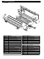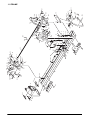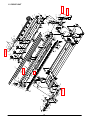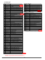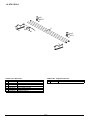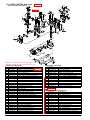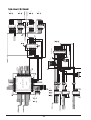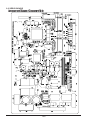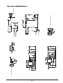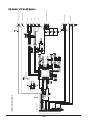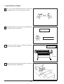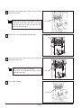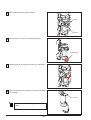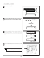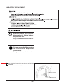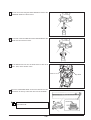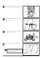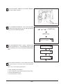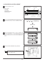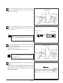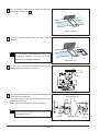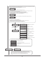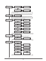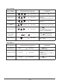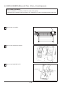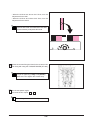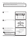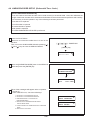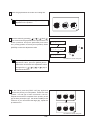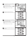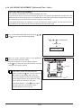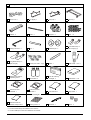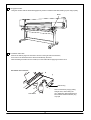
1
SERVICE NOTES
Confidential
TERMS OF USE
Users of this Service Note shall be deemed to agree with the following Terms of Use.
1. USERS
This Service Note is only for authorized persons with user ID and password issued by Roland DG Corporation.
2. PURPOSE
Authorized persons can use this Service Note only for the purposes of selling and providing to the customers
maintenance service of SP-540V.
3. REUSE
Authorized persons shall not disclose, transfer, rent or distribute this Service Note to, or allow this Service Note
to be used in any manner by, any third party other than authorized persons.
4. REPRODUCTION
Authorized persons shall not copy, change or alter this Service Note without permission of Roland DG
Corporation.
5. EFFECT OF VIOLATION
Regardless of circumstances, we will vigorously respond to any violation hereof, through legal action.
Copyright © 2007 ROLAND DG CORPORATION
8767-11
Contents
4 Adjustment
1 Structure & Spare Parts
1-1 COVERS
1-2 FRAME
1-3 DRIVE UNIT
1-4 HEAD CARRIAGE
1-5 BASE FRAME
1-6 CHASSIS
1-7 PINCH ROLL
1-8 STAY ROLL
1-9 TOOL CARRIAGE
1-10 WIPER SYSTEM
1-11 PUMP SYSTEM
1-12 INK SYSTEM
1-13 ACCESSORIES & STAND
1-1
1-2
1-4
1-6
1-7
1-8
1-9
1-10
1-11
1-12
1-13
1-14
1-15
2 Electrical Section
2-1
2-2
2-3
2-4
2-5
2-6
WIRING MAP
MAIN BOARD
SERVO BOARD
HEATER BOARD
SUB BOARD
MAINTENANCE PARTS LIST
2-1
2-3
2-10
2-16
2-19
2-24
4-1 SPECIAL TOOLS
4-2 SERVICE MODE
4-3 HOW TO UPGRADE FIRMWARE
4-4 HEAD ALIGNMENT
4-5 LMIT POSITION & CUT DOWN POSITION INITIALIZE
4-6 LINEAR ENCODER SETUP
4-7 CROP MARK SENSOR ADJUSTMENT
4-8 TOOL/CROP MARK SENSOR POSITION ADJUSTMENT
4-9 PRINT/CUT POSITION ADJUSTMENT
4-10 CALIBRATION (FEEDING DIRECTION)
4-11 TOOL HEIGHT ADJUSTMENT
4-12 TOOL PREASSURE ADJUSTMENT
4-13 CARRIAGE WIRE TENSION ADJUSTMENT
4-14 CAP HEIGHT ADJUSTMENT
4-1
4-2
4-17
4-20
4-29
4-33
4-35
4-37
4-40
4-42
4-44
4-47
4-51
4-54
5 Supplemental Information
5-1 SENSOR MAP
5-1
6 Troubleshooting
6-1 INK DROPS ON MEDIA / WHITE FINE LINE / BANDING /
6-1
MISSING DOT / SCRATCHY PRINTING / BLURRED PRINTING
3 Replacement of Main Parts
3-1 HEAD REPLACEMENT
3-2 WIPER REPLACEMENT
3-3 CAP TOP REPLACEMENT
3-4 TOOL CARRIAGE REPLACEMENT
3-5 CARRIAGE MOTOR REPLACEMENT
3-6 PUMP REPLACEMENT
3-7 INK TUBE REPLACEMENT
3-8 BATTERY REPLACEMENT
3-9 CARRIAGE WIRE REPLACEMENT
3-10 ENCODER SCALE REPLACEMENT
3-11 PINCH ROLELR REPLACEMENT
3-12 CUTTER PROTECTION REPLACEMENT
3-13 SW POWER SUPPLY REPLACEMENT
3-14 FLEXIBLE CABLE REPLACEMENT
3-2
3-8
3-10
3-15
3-19
3-24
3-28
3-33
3-35
3-40
3-43
3-44
3-45
3-46
6-2 DOES NOT PRINT AT ALL
6-3 SHIFTING IN PRINTING
6-4 VERTICAL BANDING
6-5 PRINT DOES NOT MATCH WITH CUT
6-6 STITCH CUT
6-7 START AND END POINTS DO NOT MATCH
6-8 DISTORTED FIGURE
6-9 MEDIA SHIFTING
6-10 MOTOR ERROR
6-11 HEATER TEMPERATURE FAILS
TO REACH THE PRESET VALUE
6-12 DOESN'T CONTROL THE THEMPERATURE
6-13 ERROR MESSAGE
6-14 SERVICE CALL
6-2
6-3
6-3
6-4
6-5
6-6
6-7
6-7
6-8
6-9
6-9
6-10
6-10
7 Service Activities
7-1 INSTALLATION CHECK LIST
7-2 MAINTENANCE CHECK LIST
7-3 SPECIFICATION
Windows and MS-DOS are registered trademark or trademark of Microsoft Corporation in the United States and/or other countries.
7-1
7-13
7-15
Revision Record
Revision
No.
Date
Description of Changes
0
2004.10.14
First Edition
1
2004.10.25 1-7 : PINCH ROLLER Parts No. have been changed.
Approval Issued
Inagaki
Sato
Inagaki
Sato
2
2005.1.6 1-3 : DRIVE UNIT, 1-4 : HEAD CARRIAGE Parts has been revised.
Inagaki Mabuchi
3
2005.1.28 2-6 : MEINTENANCE PARTS LIST_Electrical Parts has been revised.
Inagaki Mabuchi
4
2005.6.21
5
3-14 : FLEXIBLE CABLE REPLACEMENT has been added.
6-10 : MOTOR ERROR <ERROR LIST> has been revised.
Kato
Mabuchi
2005.7.15 1-4 : HEAD CARRIAGE Parts has been revised.
Kato
Hioki
6
2005.9.13 1-3 : DRIVE UNIT, 1-10 : WIPER Parts has been revised.
Kato
Hioki
7
2006.1.12 1-4 : HEAD CARRIAGE Parts has been revised.
Kato
Misako
8
2006.12.26
Kato
Misako
3-8 : BATTERY REPLACEMENT Procedures have been revised.
1-11: PUMP SYSTEM Parts have been revised.
9
2007.1.9 1-5 : BASE FRAME Parts have been revised.
Kato
Misako
10
2007.4.26 1-4 : HEAD CARRIAGE Parts has been revised.
Kato
Satoru
11
1-3 : DRIVE UNIT, 1-4 : HEAD CARRIAGE, 1-10 : WIPER, 1-11:
PUMP SYSTEM,
2007.12.7 1-13 : ACCESSORIES & STAND Parts have been revised.
Sect 3 : "WARNING" has been added.
4-2 : SERVICE MODE SYSTEM SWITCH has been revised.
Kato
Misako
To Ensure Safe Work
About
and
Notices.
Used for instructions intended to alert the operator to the risk of death
or severe injury should the unit be used improperly.
Used for instructions intended to alert the operator to the risk of injury
or material damage should the unit be used improperly.
* material damage refers to damage or other adverse effects caused
with respect to the home and all its furnishings, as well to domestic
animals or pets.
About the Symbols
symbol alerts the user to important instructions or warnings. The specific
The
meaning of the symbol is determined by the design contained within the triangle.
The symbol at left means “danger of electrocution”.
The
symbol alerts the user to items that must never be carried out (are
forbidden). The specific thing that must not be done is indicated by the design
contained within the circle.
The symbol at left means not to touch.
The
symbol alerts the user to things that must be carried out. The specific
thing that must be done is indicated by the design contained within the circle. The
symbol at left means the power-cord plug must be unplugged from the outlet.
In addition to the
and
: Tips and advise before the adjustment.
symbols, the symbols shown below are also used.
Turn off the primary power SWs
for the Printer and Dryer before
servicing.
Do not recharge, short-circuit,
disassemble the lithium battery, nor
put it into fire.
It may cause heat, explosion and fire.
Put tape around the lithium battery
for insulation for disposal or
preservation.
It may cause heat, explosion and fire.
About the Labels Affixed to the Unit
These labels are affixed to the body of this product.
The following figure describes the location.
HIGH VOLTAGE,
HANDLING ATTENTION
• Do not touch during power on
Electric shock, Compornents damage
• Do not repair. Replace power unit.
• Do not replace fuse. Can not be recovered.
Electric charge.
Do not touch when power is on.
The wiring terminal untended for connection of the protective earthing conductor associated with the supply
wiring.
Do not disconnect the cable of this terminal except the
time of replacement.
1 Structure & Spare Parts
1-1 COVER
S8
S8
S10
7
S8
8
S4
11
S10
S4
S8
10
32
S3
S4
28
5
S3
S3
14
S1
1
2
12
S6
29
30
S5
S1
S7
S1
S1
S3
34
S2
34
S1
4
22
34
32
S9
13
S3
9
34
23
12
S4
26
S10
S4
34
S3
30
31
S3
34
29
24
19
20
S11
S3
S6
18
15
17
3
S4
33
16
25
27
6
PARTS LIST -Main Parts1
2
3
4
5
6
7
8
9
10
11
12
13
14
15
16
17
18
19
20
22
23
24
Parts No.
22095156-00
22095158-00
22805567-00
23415133-00
23415112-00
22045135-00
22045114-01
22045371-00
22045376-00
22045134-00
22045373-00
12239406-00
22195140-00
21655310-00
21645106-00
22495211-00
22495210-00
22535287-00
22535443-00
22535390-00
22535453-00
22535452-00
22535330-00
PARTS LIST -Main Parts-
Parts Name
APRON,FRONT AL SP-540V
APRON,FRONT UNDER SP-540V
ASS'Y,FRONT COVER SP-540V
ASS'Y,THERMISTOR CABLE SP-300
ASS'Y,THERMOSTAT CABLE SP-300
COVER,INK SYSTEM SP-300
COVER,MAINTENANCE INKHEAD SP-300
COVER,INK CARTRIDGE SP-540V
COVER,RAIL F SP-540V
COVER,SIDE L SP-300
COVER,TOP SP-540V
CUSHION,TM-96-6
FRAME,COVER F SP-540V
HOLDER,COVER F SP-540V
HOOK,INT SW FJ-540
KEYTOP,DS-LD1H BLK
KEYTOP,DS-LX1H BLK
LABEL,CAUTION CARRIAGE #LA266
LABEL,MEDIA CLAMP SP-300
LABEL,EMERGENCY STOP #LA496
LABEL,VERSACAMM SP-300 #LA649
LABEL,VOLTAGE SW SP-300 #LA648
LABEL,WARNING SOL INK #LA396
25
26
27
28
29
30
31
32
33
34
Parts No.
W840605010
22055690-00
22055356-00
15099124-00
22155958-00
21475189-00
21475155-00
22715468-00
22715355-00
21425110-00
Parts Name
PANEL BOARD SP-300
PLATE,FRONT COVER SP-540V
PLATE,F COVER CM-500
SENSOR,US-602SXTLAS 65OFF 50ON
SHAFT,COVER F FJ-540
SHEET,HEATER RUBBER SP-540V
SHEET,PANEL SP-300
STAY,HEATER HOLDER F SP-540V
STAY,PANEL SP-300
WASHER,COVER FJ-50
PARTS LIST -Supplemental PartsS1
S2
S3
S4
S5
S6
S7
S8
S9
S10
S11
1-1
Parts No.
31329601-00
31289112-00
31289102-00
31289111-00
31279106-00
31149703-00
31019148-00
31049169-00
31089110-00
31139103-00
31019116-00
Parts Name
CLAMP,INSULOK T-18S
CUPSCREW, M3*10 NI
CUPSCREW, M3*6 NI
CUPSCREW, M4*6 NI
LABEL,CAUTION HOT SURF NO.778
RING,E-RING ETW-4 UNI-C
SCREW,BINDING M2.6*4 C
SCREW,CAP M4*8 BC+PW4*10*0
SCREW,PAN M3*4 C+PW
SCREW,PLAPOINT M4*6 WH FE
SCREW,BINDING M3*6 BC
33
34
S14
31
S14
1-2
S4
18
24
50
S14
S14
41
S14
29
S8
14
3
35
S11
S12
21
42
8
45
38
S13 S14
26 43 6
48
6 S7
S14
49
7
4
S8
S7
1
12
19
S8
S13
S13
S5
13
20
39
44
S4
55
S3
27
S2
S4
S15
13
47
S3
S3
S8
23
S17
17
S20
37
S12
36
25
15
S3
S9
S8
S12
10 S9
S1
15
S16
40
2
5
S3
28 9
S14
S10
S19
11
S14
S12
1
51
4
46
S6
S14
S18
30
S14
54
52
S3
S12
8
22
S5
S13
53
S11
S1
1-2 FRAME
1-2 FRAME
PARTS LIST -Main Parts1
2
3
4
5
6
7
8
9
10
11
12
13
14
15
16
17
18
19
20
21
22
23
24
25
26
27
28
29
30
31
33
34
35
36
37
38
39
40
41
42
43
44
45
46
47
48
49
50
51
52
53
54
55
Parts No.
21905192-00
7520501000-00
22845192-00
22845104-00
21985140-00
12159573-00
12159563-00
12159508-00
23415129-00
23415113-00
23415114-00
23415126-00
23415271-00
21745109-00
22045186-00
22025980-00
22045372-00
22045374-00
22045375-00
W876705040-00
22195145-00
22195146-00
22195105-00
22195148-00
22195149-00
22305101-00
W876705020-00
W840605020-00
22485104-00
22535444-00
22535441-00
22535442-00
22535330-00
22485108-00
12399102-00
22155763-00
22175105-00
W840605080-00
22055474-00
22055589-00
22055598-00
22145393-00
22295302-00
22035196-00
22715347-00
22715467-00
22715351-00
22715350-00
22715348-00
22785101-00
22715465-00
22055644-00
W876705060-00
23415272-00
PARTS LIST -Supplemental Parts-
Parts Name
ADAPTER,MEDIA CLAMP SP-540V
ASS'Y,CAP BOTTLE 2 FJ-52
BASE,BOTTOM SP-540V
BASE,RAIL SP-300
BRACKET,INK CATCH TANK SP-540V
BUSH,80F-0603
BUSH,80F-1006
BUSH,SHAFT OILES 80F-1206
CABLE ASS'Y,FAN SP-300
CABLE ASS'Y,FRONT COVER SW SP-300
CABLE ASS'Y,MNT. COVER SW SP-300
CABLE ASS'Y,LOADING SENSOR SP-300
CABLE-ASSY,V SELECTOR SP-540V
COLLAR,LEVER FJ-540
COVER,INK SYSTEM SW SP-300
COVER,INT SW FJ-540
COVER,SCAN MOTOR SP-540V
COVER,UNDER L SP-540V
COVER,UNDER R SP-540V
FAN JUNCTION BOARD SP-540V
FRAME,MIDDLE L SP-540V
FRAME,MIDDLE R SP-540V
FRAME,SCAN MOTOR SP-300
FRAME,SIDE L SP-540V
FRAME,SIDE R SP-540V
GUIDE,LEVER SP-300
HEATER POWER BOARD SP-540V
JUNCTION BOARD 1 SP-300
KNOB FJ-50
LABEL,READ MANUAL #LA637
LABEL,SET INK SP-300 #LA634
LABEL,USE ONLY ECO-SOL #LA635
LABEL,WARNING SOL INK #LA396
LEVER,CAM PINCH SP-300
MAGNET CATCH TL-105
OILES BUSH 80F-0806
PINCH ROLL SPRING
PINCH U/D SENS BOARD SP-300
PLATE,INK CATCH TANK FJ-52
PLATE,LEVER LINK SP-300
PLATE,SQUARE SHAFT SUPPORT SP-300
SHAFT,JOINT PNC-960
SHAFT,SQUARE SP-540V
STAND,LEVER SP-300
STAY,FRAME SIDE R SP-300
STAY,HEATER BOARD SP-540V
STAY,LEVER ADJUSTOR SP-300
STAY,PINCH LEVER SP-300
STAY,INK CARTRIDGE SUPPORT SP-300
SUPPORT,FRAME R SP-300
STAY,EXT BOARD SP-540V
PLATE,CONNECTOR TS-30
EXT BOARD SP-540V
CABLE ASS'Y,FAN JUNCTION SP-540V
S1
S2
S3
S4
S5
S6
S7
S8
S9
S10
S11
S12
S13
S14
S15
S16
S17
S18
S19
S20
1-3
Parts No.
31029101-00
31029106-00
31289102-00
31289111-00
31119904-00
31149706-00
31149705-00
31409801-00
31019149-00
31019116-00
31049142-00
31049117-00
31049137-00
31049169-00
31089110-00
31239125-00
31369102-00
31289105-00
31049171-00
31129101-00
Parts Name
BUSH,NB-19
BUSH,SQUARE SB-6025
CUPSCREW, M3*6 NI
CUPSCREW, M4*6 NI
PIN,SPRING 2.5*8 SUS STRAIGHT
RING,E-RING ETW-10 SUS
RING,E-RING ETW-7 SUS
SADDLE,LOCKING WIRE LWS-0711Z
SCREW,BINDING M2.3*8 BC
SCREW,BINDING M3*6 BC
SCREW,CAP M3*6BC
SCREW,CAP M4*12 BC+PW
SCREW,CAP M4*25 BC
SCREW,CAP M4*8 BC+PW4*10*0.8
SCREW,PAN M3*4 C+PW
SCREW,W-SEMS M3*8 SUS
SPACER,PCB SUPPORT PCB-8S
CUPSCREW, M3*6BC
SCREW,CAP M3*12NI
PIPE,POLYCA3*6*8
74
73
S15
S13
1-4
17
S15
S13
S1
S9
21
S13
S6
S8
14
54
18
REVISED 6
47 1
38 S13
S9
27
S7
30
6
S13
S20
S2
S10
46
S11
32
S13
51
58
S1 26
S17
48
S10
S13
S5
S11
36
35
42
37
R 11
29
S24
S1
REVISED 11
S24
57
S3
29
16
S13
S23
S1
50
29
S3
S1
33
24
S16
22
25
72
70
66
10
56
5
24
S13
S1
55
S14 S4
12
65 S9
S11
33
64 60 63
61
62
S13
28
15
S3
S1
33
24
68
64
S1
69
60
63
S3
71
S1
33
24
67 61
REVISED 2
44
S1 7
31
16
S4
S22
40
S13
45
3
53
9
15
23
S3
19
24
4
S13
39
S12
59
S13
53
49
43
8
76
2
REVISED 11
REVISED 6
S4
13
S8
75
S21 S13
38
34
20
38
S12
S3
41
S12
52
24
S12 47
S4
S18
11
1-3 DRIVE UNIT
1-3 DRIVE UNIT
PARTS LIST -Main PartsPARTS LIST -Main PartsParts No.
Parts No.
Parts Name
Parts Name
1 7876709020
ASS'Y, FEED MOTOR SP-540V REVISED 6 *1 68 22805578-00 ASS'Y TUBING 3*1000MM SP-540V
2 7876709010
ASS'Y,SCAN MOTOR SP-540V REVISED 6
69 22805478-00 ASS'Y TUBING 2*20MM FJ-540
3 11869103-00
BALL,4MM
70 22535517-00 LABEL,PINCH ROLL SP-540V #LA740
4 22845111-00
BASE,SCAN MOTOR SP-300
71 22535518-00 LABEL,PINCH ARROW SP-50V #LA739
5 23415123-00
CABLE ASS'Y,CUT CAR.ORG. SP-300
72 22715469-00 STAY,HOLD SHAFT SQUARE SP-540V
6 23415124-00
CABLE ASS'Y,GRIT MOTOR SP-300
73 22715466-00 STAY,FA-CODER SP-540V
7 23415127-00
CABLE ASS'Y,PRI. CAR. ORG. SP-300
74 25095120-00 GRIT ENCODER TS5217N561 FJ-540
8 23415125-00
CABLE ASS'Y,SCAN MOTOR SP-300
75 1000003821 SPACER,FLANGE VP-540
REVISED11
9 21365103-00
CASE,LOCK CJ-70
76 1000003822 BASE,FLANGE VP-540
10 22045130-00
COVER,CAP MOTOR SP-300
11 12049377-00
COVER,TKPO180-2B R50-63
PARTS LIST -Supplemental PartsParts No.
12 W840605070-00 CUT ORIGIN BOARD SP-300
Parts Name
13 1000003824
FRANGE,MOTOR SCAN SP-540V REVISED11
S1 31289102-00 CUPSCREW, M3*6 NI
14 21995122-00
FLANGE,MOTOR FJ-540
S2 31129102-00 PIPE,POLYCA 4*8*10
15 W8406050C0-00 FLEX1 SP-300
S3 31299102-00 RIVET,NYLON P2655B
16 W8406050D0-00 FLEX2 SP-300
S4 31409801-00 SADDLE,LOCKING WIRE LWS-0711Z
17 22195144-00
FRAME,FEED MOTOR SP-540V
S5 31019149-00 SCREW,BINDING M2.3*8 BC
18 22195108-01
FRAME,SUPPORT AUTO CUTTER SP-300
S6 31019703-00 SCREW,BINDING P-TIGHT 3*8 BC
19 22195150-00
FRAME,RAIL SUPPORT SP-540V
S7 31049155-00 SCREW,CAP M3*12 BC WSH 3*6*0.5
20 21685149-00
GEAR,H235S20(B8)T2
S8 31049170-00 SCREW,CAP M3*8 NI
21 21685128-00
GEAR,H300 S10(B6C16POM)
S9 31049117-00 SCREW,CAP M4*12 BC+PW
22 22305109-00
GUIDE,CABLE FLEX-CUT SP-540V
S10 31049174-00 SCREW,CAP M4*15 NI
23 22305103-00
GUIDE,CABLE CARD SP-300
S11 31049137-00 SCREW,CAP M4*25 BC
24 22135559-00
GUIDE,TUBE 8 FJ-500
S12 31069104-00 SCREW,CAP M4*6+FL C
25 W876705060-00 FLEX3 SP-540V
S13 31049169-00 SCREW,CAP M4*8 BC+PW4*10*0.8
26 21655131-00
HOLDER,LINEAR SCALE CJ-70
S14 31089110-00 SCREW,PAN M3*4 C+PW
27 22115121-00
HOUSING,R-BEARING FRAME FJ-540
S15 31199701-00 SCREW,SET WP M3*3 C
28 22535388-00
LABEL,G-ROLLER 170 CJ-540 #LA487
S16 31239103-00 SCREW,W-SEMS M3*8 BC+PW12*1
29 22535387-00
LABEL,G-ROLLER 50 CJ-540 #LA486
S17 31249217-00 WASHER,PLAIN 4*8*1 C
30 21895169-00
L-BEARING,LWES15C3R2160QE
S18 31149704-00 RING,E ETW-6 SUS
31 21345111-00
LOCK,STAY SP-540V
S20 31289108-00 CUPSCREW, M3*8 NI
32 22055316-00
PLATE,LINEAR SCALE CJ-70
S21 31289107-00 CUPSCREW, M3*12 NI
33 22055591-00
PLATE,TUBE GUIDE SP-300
S22 31049112-00 SCREW,CAP M4*10 BC
34 21975157-00
PULLEY,HD48.46S16(B35C39.5 F53)
S23 31409811-00 SADDLE,LOCKING WIRE LWS-1211Z
35 21975154-00
PULLEY,UD49.2S4(B4.6C6.6)
S24 3000000096 TAPE,UHMW-PE 3965 19MM*30M
REVISED11
36 22645127-00
RAIL,GUIDE SP-540V
37 22645129-00
RAIL,LINEAR SCALE SP-540V
*1
Revised 6 Refer to the Service Information SP-540V-007.
38 22175815-00
BEARING F8-1622
39 15229506-00
SENSOR INTERRUPTER,GP1A05A5
40 22295117-00
SHAFT,LOCK CJ-70
41 22155963-00
SHAFT,PULLEY FJ-540
42 21475188-00
SHEET,LINEAR SCALE SP-540V
43 21475187-00
SHEET,RAIL CABLE SP-540V
44 22185101-00
SLIDER,LOCK CJ-70
45 22175134-00
SPRING,A CJ-70
46 22175122-00
SPRING,BACKUP PNC-960
47 22175157-00
SPRING,C P-ROLLER CM-500
48 22035172-00
STAND,PULLEY SP-300
49 22715462-00
STAY,COVER FLEX CABLE SP-540V
50 22715361-00
STAY,GUIDE RAIL LB SP-300
51 22715379-00
STAY,GUIDE RAIL LF SP-300
52 22715363-00
STAY,PULLEY SHAFT SP-300
53 22715356-00
STAY,GUIDE RAIL SUPPORT SP-300
54 22135346-00
STOPPER,CAM CM-500
55 22135441-00
STOPPER,LINEAR SCALE FJ-540
56 22785115-00
SUPPORT,CABLE SP-540V
57 21945149-00
WIRE,SCAN DRIVE SP-540V
58 23415114-00
CABLE-ASS'Y,MAINT-COVER SW SP-300
59 22805471-00
ASS'Y,PULLEY HD48.46S16 FJ-540
60 11909168
ADAPTER,TUBE 2-3FAI FJ-540
61 11909133
ADAPTER,SCREW 2FAI FJ-50
ADAPTER,SCREW 3FAI FJ-540
62 11909167-00
HOLDER,RING O 2FAI FJ-50
63 11659149
HOLDER,RING O 3FAI FJ-540
64 11659249-00
65 22055697-00
PLATE,SHAFT SQUARE SP-540V
66 22805555-00
ASS'Y,TUBING 2*1600MM SP-540V
REVISED 2
67 22805479-00
ASS'Y,TUBING 2*100MM FJ-540
*REVISED 11:No.13,75,76 Refer to the Service Information SP540V-017.
*REVISED 11:No.S24 Refer to the Service Information SP540V-019.
1-5
1-4 HEAD CARRIAGE
S4
S5
S9
S5
S1
13
15
21
12
9
4
S2
4
REVISED 2,7
S2
30
32 42
S11
38
S3
S8
S2 29
1
33
35
1
36
18
S10 S7
S2
24
S8
10
S14
S3
29
S7
5
6
10
27
28
16
S5
S8
REVISED 5
8
39
38
REVISED 11
3
34
S14
25
REVISED 2,7
14
11
S4
S3
22
41
S6
7 S2 31
26
23 S2
S2
2
14
REVISED 10
40
S2
35
S2
S2
17
S12
S13
S2
20
S12
S2
S13
19
37
S2
19
S2
PARTS LIST -Main Parts1
2
3
4
5
6
7
8
9
10
11
12
13
14
15
16
17
18
19
20
21
22
23
24
25
26
27
28
29
30
Parts No.
21905166-00
11909133-00
1000002201
22805555-00
22845193-00
22845194-00
23415274-00
23475214-00
23475240-00
21775103-00
22045140-00
22045365-00
12049138-00
6081181200
12399352-00
22195141-00
22195142-00
22195143-00
22135618-00
22135440-00
21655311-00
11659149-00
22485111-00
21345105-00
22395108-00
15229705-00
1000000134
22055547-00
22055548-00
W8406050F0-00
REVISED 2
REVISED 5
REVISED 7
REVISED 10
REVISED 11
Refer to the Service Information : SP540V-003
Refer to the Service Information : SP540V-004
Refer to the Service Information : SP540V-008
Refer to the Service Information : SP540V-009
Refer to the Service Information : SP540V-013
PARTS LIST -Main Parts-
Parts Name
ADAPTER,HEAD FJ-540
ADAPTER,SCREW 2FAI FJ-50
ASSY,HEAD INKJET SOL XC-540 REVISED 11
ASS'Y,TUBING 2*1600MM SP-540V
BASE,CARRIAGE AL SP-540V
BASE,CARRIAGE HOLDER SP-540V
CABLE-ASSY,HEAD U/D SENS SP-540V
CABLE-CARD,21P1 180L BB
CABLE-CARD,36P1 2670L BB
CAM,CARRIAGE FJ-540
COVER,HEAD BOARD SP-300
COVER,PRINTING CARRIAGE SP-540V
COVER,TKPO180-2B R50-44
ASSY,INK DAMPER 3 2FAI SJ-540 REVISED 2,7
FILTER(E) FRC-45-12-6.5
FRAME,CARRIAGE SIDE L SP-540V
FRAME,CARRIAGE SIDE R SP-540V
FRAME,CARRIAGE U/D SP-540V
GUIDE,CARRIAGE CAP FJ-540
GUIDE,HEAD AL FJ-540
HOLDER,CABLE SP-540V
HOLDER,RING O 2FAI FJ-50
LEVER,CARRIAGE SP-540V
LOCK,CJ-500
MAGNET,CJ-500
PHOTO INTERRUPTER GP1A71A1
REVISED 5
PLATE,DAMPER SP-540V
PLATE,GND FJ-540
PLATE,SLIDER CARRIAGE FJ-540
PRINT CARRIAGE BOARD SP-300
1-6
Parts No.
Parts Name
31 W840605050-00 PRINT LINEAR ENCORDER BOARD SP-300
32
22295303-00 SHAFT,HEXAGON CARRIAGE SP-540V
33
22185127-00 SLIDER,CARRIAGE FJ-540
34
22165216-00 SPACER,U/D LEVER FJ-540
35
22175159-00 SPRING,CARRIAGE SIDE FJ-50
36
22175520-00 SPRING,HEAD ADJUST 500 FJ-540
37
22175519-00 SPRING,HEAD PLESS 500 FJ-540
38
22625109-00 SPRING,PULL CARRIAGE 3500 FJ-540
39
1000000417 STAY,ENCORDER SENSOR SP-540V REVISED 10
40
22715362-00 STAY,HOLDER CARRIAGEBOARD SP-540V
41
22715472-00 STAY,SENSOR CARRIAGE SP-540V
42
22785116-00 SUPPORT,CARRIAGE BOARD SP-540V
PARTS LIST -Supplemental PartsS1
S2
S3
S4
S5
S6
S7
S8
S9
S10
S11
S12
S13
S14
Parts No.
31379101-00
31289102-00
31149703-00
31299102-00
31409801-00
31019148-00
31799103-00
31069104-00
31049169-00
31679902-00
31089121-00
31199905-00
31179908-00
31239114-00
Parts Name
CLAMP,FLAT CABLE FCS-50P
CUPSCREW, M3*6 NI
RING,E-RING ETW-4 UNI-C
RIVET,NYLON P2655B
SADDLE,LOCKING WIRE LWS-0711Z
SCREW,BINDING M2.6*4 C
SCREW,CAP M3*15 NI
SCREW,CAP M4*6+FL C
SCREW,CAP M4*8 BC+PW4*10*0.8
SCREW,C-SEMS M2*8 C
SCREW,PAN M2.3*8 NI +PW2*6*0.4
SCREW,SET CONE M3*16 BC
SCREW,UREA N-1 M3*20 WH
SCREW,W-SEMS M3*8 C
1-5 BASE FRAME
Revised 9
S4
S12
14
S2
2
S17
11
S13
22
S3
13
S2
1
21
7
15
S4
S15
S3
S2
5
S12
27
S7
S10
17
16
S11
S3
18
8
6
S9
12
S11
21
S11
18
6
23
S4
28
S3
S13
27
S11
28
S8
S6
S6
S1
S14
S5
S8
24
S12
15
23
S4
10
S14
25
S1
S7
S5
S6
26
S13
S7
24
S6
S7
S10
S5
S14
25
S12
10
26
S13
S10
25
26
S13
S10
PARTS LIST -Main PartsParts No.
Parts Name
1 22805570-00 ASS'Y, GRIT ROLLER SP-540V
2 22095157-00 APRON,B SP-540V
3 22115106-00 BEARING HOUSING A 211-106
4 22175870-00 BEARING 10-19ZZ
5 22005144-00 BED,SP-540V
6 23415118-00 CABLE ASS'Y,PAPER SENSOR SP-300
7 23415133-00 CABLE-ASS'Y,THERMISTOR SP-300
8 23415112-00 CABLE-ASS'Y,THERMOSTAT SP-300
9 22165165-00 COLLAR
10 21715110-00 FAN SCBD24H7-016
11 22195147-00 FRAME,SIDE BED L SP-540V
12 22195110-00 FRAME,SIDE BED R SP-300
13 22535452-00 LABEL,VOLTAGE SW SP-300 #LA648
14 21545137-00 PAD,CUTTER CM-500
15 22055599-00 PLATE,SHUTTER END SP-300
16 22055698-00 PLATE,SHUTTER SP-540V
17 15099124-00 SENSOR,US-602SXTLAS 65OFF 50ON
18 15099115-00 SENSOR-INTERRUPTER GP2A25NJ
19 22075126-00 SET,GRIT ROLLER CJ-540 *include 9 Rollers
20 22295301-00 SHAFT,FEED SP-540V
21 21475189-00 SHEET,HEATER RUBBER SP-540V
22 21625106-00 SHUTTER,BED SP-540V
23 22125432-00 SHUTTER,FAN FJ-540
24 21625103-00 SHUTTER,HEATER CORD SP-300
25 22165229-00 SPACER,BED LOWER SP-540V
26 22165230-00 SPACER,BED UPPER SP-540V
27 22715468-00 STAY,HEATER HOLDER SP-540V
28 22715352-00 STAY,PAPER SENSOR SP-300
PARTS LIST -Supplemental PartsParts No.
Parts Name
S1 31029101-00 BUSH,NB-19
S2 31329601-00 CLAMP,INSULOK T-18S
S3 31289112-00 CUPSCREW, M3*10 NI
S4 31289102-00 CUPSCREW, M3*6 NI
S5 31179106-00 SCREW,JACK UP SP-540V
S6 31129102-00 PIPE,POLYCA 4*8*10
S7 31299102-00 RIVET,NYLON P2655B
S8 31409801-00 SADDLE,LOCKING WIRE LWS-0711Z
S9 31019148-00 SCREW,BINDING M2.6*4 C
S10 31019703-00 SCREW,BINDING P-TIGHT 3*8 BC
S11 31049170-00 SCREW,CAP M3*8 NI
S12 31049137-00 SCREW,CAP M4*25 BC
S13 31049169-00 SCREW,CAP M4*8 BC+PW4*10*0.8
S14 31049117-00 SCREW,CAP M4*12 BC+PW
S15 31089110-00 SCREW,PAN M3*4 C+PW
S16 31199704-00 SCREW,SET WP M3*8 BC
S17 31329501-00 CLAMP,PUSH MOUNT RT30SSF5
1-7
1-6 CHASSIS
18
S2
S1
S6
S1
S1
S2
S6
S5
25 S5
17
S5
26 5
28
24 3
23
S1 S10
S3
11
S9
29
31
10
S12
S10
4
2
S6
S3
S7
S11
6 30
S8
27 S5
22
19
7
1
21
16
S13
8 S5
20
S4
34
Parts No.
15009101-00
23505631-00
23505632-00
23415268-00
23415116-00
23415269-00
23415270-00
23415111-00
23415117-00
23415115-00
23415109-00
23415132-00
23475197-00
23475211-00
23475217-00
23475212-00
23475112-00
22815156-00
11769118-00
22045369-00
12399352-00
12559105-00
W876705010-00
13429702-00
22535257-00
22535117-00
W876705030-00
13129170-00
12429114-00
7876705100-00
7840605600-00
23415273-00
12
15
S5
33
PARTS LIST -Main Parts-
S4
9
14
S5
1
2
3
4
5
6
7
8
9
10
11
12
13
14
15
16
17
18
19
20
21
22
23
24
25
26
27
28
29
30
31
32
32
13
35
PARTS LIST -Main Parts-
Parts Name
BATTERY CR2032
CABLE-ASS'Y JUNBI A PC-600
CABLE-ASS'Y JUNBI B PC-600
CABLE-ASSY AC GROUND GREEN SP-540V
CABLE ASS'Y,JUNBI D SP-300
CABLE-ASSY,AC SWPS POWER SP-540V
CABLE-ASSY POWER H AC SP-540V
CABLE ASS'Y,POWER H DC SP-300
CABLE ASS'Y,POWER MAIN SP-300
CABLE ASS'Y,POWER SERVO SP-300
CABLE ASS'Y,RELAY JUNCTION SP-300
CABLE ASS'Y,THERMO JUNC. SP-300
CABLE-CARD 25P1 105L BB
CABLE-CARD,14P1 350L BB
CABLE-CARD,18P1 80L BB
CABLE-CARD,24P1 600L BB
CABLE-CARD,26P1 700L BB
CHASSIS,SP-540V
CLAMP,FCM2-S6-14
COVER,CHASSIS SP-540V
FILTER(E) FRC-45-12-6.5
FUSE,5X20 21706.3 6.3A/250V
HEATER CONTROL BOARD SP-540V
INLET AC-P01CF01 15A250V
LABEL,CAUTION VOLTAGE #LA167
LABEL,POWER CM-500 NO.893
POWER JUNCTION BOARD SP-540V
POWER SW AJ7201B
POWER UNIT,ZWS150PAF-36/J
SP-540V MAIN BOARD ASS'Y
SP-300 SERVO BOARD
CABLE-ASSY,EXT JUNCTION SP-540V
Parts No.
33 21475147-00 SHEET,COATING SEAL FJ-540
34 22055695-00 PLATE,NET CARD SP-540V
35 22805353-00 ASS'Y,NETWORK BOARD FJ-500
PARTS LIST -Supplemental PartsS1
S2
S3
S4
S5
S6
S7
S8
S9
S10
S11
S12
S13
1-8
Parts No.
31029106-00
31379101-00
31329601-00
31289105-00
31289102-00
31289111-00
31279116-00
31279121-00
31279191-00
31409801-00
31169103-00
31369101-00
31209118-00
Parts Name
BUSH,SQUARE SB-6025
CLAMP,FLAT CABLE FCS-50P
CLAMP,INSULOK T-18S
CUPSCREW, M3*6 BC
CUPSCREW, M3*6 NI
CUPSCREW, M4*6 NI
LABEL,EARTH MARK-1 NO.E-580
LABEL,FLASH-LIGHTING NO.E-582
LABEL,WARNING FUSE REPLACE #347
SADDLE,LOCKING WIRE LWS-0711Z
SCREW,FLAT M3*6 BC
SPACER,PCB SUPPORT PCB-8L
SPACER,WPCS-12S-4.0
1-7 PINCH ROLLER
<Right/Left Pinch Roller>REVISED 1
<Center Pinch Roller>
S2
S2
S4
11
17
15
9
2
2
10
16
7
1
S1
13
S1
3
3
6
6
4
4
12
12
S3
5
8
S3
S1
14
S3
PARTS LIST -Main Parts1
2
3
4
5
6
7
8
9
10
11
12
13
14
15
16
17
5
S1
S3
PARTS LIST -Supplemental Parts-
Parts No.
Parts Name
22805581-00 ASS'Y, PINCH ROLLER L/R SP-540V REVISED 1
21745101-00 COLLAR,P-ROLLER PNC-960
22195153-00 FRAME,PINCH ROLL SP-540V
22145416-00 LEVER,P-ROLLER PNC-960
22145831-00 PIN NO.1 (214-831)
22145832-00 PIN NO.2 (214-832)
22055264-00 PLATE,GUIDE P PNC-960
21565102-00 P-ROLLER TD16S4(B10) TYPE2
22625101-00 SPRING,PINCH LEFT SP-300
22625102-00 SPRING,PINCH RIGHT SP-300
22715471-00 STAY,PINCH SENSOR SP-540V
11539104-00 PIN 3*35 SUS M6
7876701500-00ASS'Y, PINCH ROLLER C SP-540V
21565103-00 P-ROLLER FD16S4(B10) TYPE2
22625120-00 SPRING,PINCH CENTER LEFT SP-540V
22625121-00 SPRING,PINCH CENTER RIGHT SP-540V
22715461-00 STAY,PINCH CENTER SP-540V
1-9
S1
S2
S3
S4
Parts No.
31149702-00
31019702-00
31249211-00
31249303-00
Parts Name
RING,E-RING ETW-3 UNI-C
SCREW,BINDING P-TIGHT 3*6 BC
WASHER,PLAIN 4.3*7*0.5 C
WASHER,SPRING M3 C
1-8 STAY ROLL
6
S1
7
5
1
3
4
2
6
S1
7
1
PARTS LIST -Main Parts1
2
3
4
5
6
7
Parts No.
22145200-00
21815106-00
22485107-00
21545139-00
22295309-00
7498805000-00
22135362-00
PARTS LIST -Supplemental Parts-
Parts Name
ARM,SP-300
BOLT,SHOULDER PNS-501
LEVER,BRAKE SP-300
PAD,BRAKE PNS-501
SHAFT,SHEET SP-540V
ASS'Y, STOPPER SCREW PNS-501
STOPPER PNS-501
Parts No.
Parts Name
S1 31109603-00 NUT, SQUARE M5
1-10
1-9 TOOL CARRIAGE
S5
S8
7
S13
S5
21
S4
S9
S7
13
10
S11
9
S4
19
S3
20
14
11
15
8
18
4
1
S4
S14
S7
16
S10
S4
S1
S12
5
2
12
17
S6
S2
3
PARTS LIST -Main Parts1
2
3
4
5
6
7
8
9
10
11
12
13
14
15
16
17
18
19
20
21
Parts No.
22805571-00
22805292-00
22805291-00
22805287-00
7488739000-00
23415119-00
22045137-00
22025269-00
W840605060-00
W8406050E0-00
22285503-00
21495115-00
15099115-00
21475148-00
22175122-00
22175154-00
22175155-00
22715168-00
22715463-00
22715464-00
23475238-00
PARTS LIST -Supplemental Parts-
Parts Name
ASS'Y CARRIAGE SP-300
ASS'Y, CLAMP BLADE CM-500
ASS'Y, HOLDER BLADE CM-500
ASS'Y, PLATE CAM SLIDE CM-500
BASE CUTTER CJ-500
CABLE ASS'Y,PINCH SENSOR SP-300
COVER,CARRIAGE BOARD SP-300
COVER,CARRIAGE CM-500
CROP MARK BOARD SP-300
CUT CARRIAGE BOARD SP-300
NUT,PENHOLDER
SCREW,BLADE SET CM-500
SENSOR-INTERRUPTER GP2A25NJ
SHEET,FILTER CROP CJ-500
SPRING,BACKUP PNC-960
SPRING,BLADE UP CM-500
SPRING,SCREW CM-500
STAY,AUTO CUTTER 2 CM-500
STAY,CUT CARRIAGE BOARD SP-540V
STAY,CUT CARRIAGE HOLDER SP-540V
CABLE-CARD,15P1 2570L BB
S1
S2
S3
S4
S5
S6
S7
S8
S9
S10
S11
S12
S13
S14
1-11
Parts No.
31029801-00
31029803-00
31329601-00
31289102-00
31299102-00
31019118-00
31019116-00
31049117-00
31049169-00
31169103-00
31089110-00
31229103-00
31249402-00
31019112-00
Parts Name
BUSH,ROLL 2*4
BUSH,ROLL 3*5
CLAMP,INSULOK T-18S
CUPSCREW, M3*6 NI
RIVET,NYLON P2655B
SCREW,BINDING M3*10 BC
SCREW,BINDING M3*6 BC
SCREW,CAP M4*12 BC+PW
SCREW,CAP M4*8 BC+PW4*10*0.8
SCREW,FLAT M3*6 BC
SCREW,PAN M3*4 C+PW
SCREW,TRUSS M2*6 BC
WASHER,EXTERNAL TOOTH M4 C
SCREW,BINDING M2.6*4 BC
6
1-10 WIPER SYSTEM
S5
6
30
31
15
S6
3
7
16
S5
S1
12
11
32
20
S1
8
3
S5
S1
9
REVISED 6
1
2
26
27
10
14
3
S4
19
17
3
S1
13
24
23
S3
S6
28
5
S2
22
4
18
11
S1
21
25
S1
S6
29
S7
32
S1
S1
* REVISED 6 Refer to Service Information : SP540-006
PARTS LIST -Main Parts1
2
3
4
5
6
7
8
9
10
11
12
13
14
15
16
17
18
19
20
21
22
23
24
25
26
27
28
29
30
31
32
Parts No.
22845107-00
11929139-00
12159536-00
23415128-00
23415120-00
22045141-00
22045129-00
22045128-00
1000000416
22275120-00
21995104-00
22195113-00
22195151-00
21685144-00
21655263-00
21655245-00
22435106-00
21545195-00
22055601-00
21975124-00
21975123-00
22645128-00
22645115-00
15229506-00
22295132-00
22295267-00
22625105-00
22175140-00
21445114-00
11379105-00
21375107-00
21985139-00
PARTS LIST -Supplemental Parts-
Parts Name
BASE,WIPER MOTOR SP-300
BELT,520P2M4-530
BUSH,B-S6-17
CABLE ASS'Y,WIPER SENOR SP-300
CABLE ASS'Y,WIPER MOTOR SP-300
COVER,SCRAPER SP-300
COVER,SERGE MIST SP-300
COVER,WIPER SP-300
FILTER(M),SERGE MIST 2 SP-300 REVISED 6
FILTER(M),SERGE MIST UNDER SP-300
FLANGE,PULLEY STX-7
FRAME,WIPER B SP-300
FRAME,WIPER F SP-540V
GEAR,S53S5(B15)
HOLDER,SCRAPER SP-300
HOLDER,WIPER FJ-540
MOTOR,103-593-1041
PAD,WIPER UNDER TYPE2 SP-300
PLATE,SERGE MIST SP-300
PULLEY,T14P2S4 + GEAR,S53
PULLEY,WD6.94S9
RAIL,WIPER GUIDE SP-540V
RAIL,WIPER R SP-300
SENSOR INTERRUPTER,GP1A05A5
SHAFT,IDLE PULLEY STX-7
SHAFT,WIPER SP-300
SPRING,SET SERGE MIST SP-300
SPRING,TENSHONER STX-7
TRAY,WIPER UNDER SP-540V
WIPER,HEAD ASP FJ-50
WIPER,SCRAPER FJ-540
BRACKET, WIPE UNDER SP-540V
1-12
S1
S2
S3
S4
S5
S6
S7
Parts No.
31289108-00
31049107-00
31149703-00
31199701-00
31239101-00
31249952-00
31139103-00
Parts Name
CUPSCREW, M3*8 NI
SCREW,CAP M3*12 BC
RING,E-RING ETW-4 UNI-C
SCREW,SET WP M3*3 C
SCREW SET, W-SEMS M3*6 3CBC 100PCS
WASHER,POLYSLIDER 2.6*5*.5 CUT
SCREW,PLAPOINT M4*6 WH FE
REVISED 11
1-11 PUMP SYSTEM_Old type
S/No. AV10472 and below
22
11
36
1 REVISED 11
19
34
15
S9
41
10
S2
S2
S2
18
3
30
S6
12
28
37
S2
S2
19
23
S13
5
9
24
S15
32
39
20
15
5
S2
26
4
S2
21
S10
13
40
28
22
S2
17 25
16
8
33
S4
2
S2
S12
S7
S1
PARTS LIST -Main Parts1
2
3
4
5
7
8
9
10
11
12
13
14
15
16
17
18
19
20
21
22
23
24
25
26
27
28
29
30
S14
S5
S2
Parts No.
1000002794
22845109-00
22845108-00
21925137-00
12529101-00
23415121-00
23415122-00
22335146-00
21365121-00
22025671-00
22195152-00
22195116-00
22195114-00
22195115-00
21685122-00
21685120-00
22135616-00
22135614-00
21655264-00
21645109-00
22435106-00
21575126-00
22055602-00
22055596-00
22055597-00
22055595-00
22565406-00
11889107-00
15229506-00
S2
S2
29
42
S13
S2
S1
S8
31
35
S2
S2
S2
29
14
S4
18
27
38
38
S8
S4
7
S2
PARTS LIST -Main Parts-
Parts Name
REVISED 11
ASSY,CAP-TOP XC-540
BASE,BOTTOM CAP SP-300
BASE,TABLE MOTOR CAP SP-300
BELT,166P2M4-530
BUSH,80FL-08
CABLE ASS'Y,CAP MOTOR SP-300
CABLE ASS'Y,PUMP MOTOR SP-300
CAP,T-SPRING FJ-540
CASE,CAP-TOP FJ-540
COVER,CAP-CASE FJ-540
FRAME,BACKUP CAP TYPE2 SP-300
FRAME,FRONT CAP SP-300
FRAME,MAIN CAP SP-300
FRAME,SIDE CAP SP-300
GEAR,S10S20
GEAR,S34S4.3
GUIDE,CAP-CASE FJ-540
GUIDE,SIDE FRAME FJ-540
HOLDER,T-SPRING SP-300
HOOK,CAP CASE TYPE2 SP-300
MOTOR,103-593-1041
NUT,TABLE FJ-540
PLATE,NUT SP-300
PLATE,PUMP MOTOR CAP SP-300
PLATE,SHUTTER TABLE SP-300
PLATE,TABLE MOTOR CAP SP-300
PULLEY T20S5(B7)
R-BEARING,D10S6(B3FL)
SENSOR INTERRUPTER,GP1A05A5
31
32
33
34
35
36
37
38
39
40
41
42
Parts No.
22295268-00
22155957-00
22165178-00
22175334-00
22175326-00
22175324-00
22715364-00
22245104-00
21965137-00
7576340000-03
22805477-00
22805572-00
Parts Name
SHAFT,TABLE GUIDE SP-300
SHAFT,SCREW M8 FJ-540
SPACER,6FAI FJ-50
SPRING,CAP-HEAD FJ-540
SPRING,TABLE FJ-540
SPRING,T-MOTOR FJ-540
STAY,NUT SP-300
STOPPER,GUIDE SHAFT SP-300
TABLE,CAP CASE SP-300
SC-500 PUMP ASS'Y FOR SOL INK
ASS'Y,TUBING 1.4*30MM FJ-540
ASS'Y, TUBING 2*80MM SP-540V
PARTS LIST -Supplemental PartsS1
S2
S3
S4
S5
S6
S7
S8
S9
S10
S12
S13
S14
S15
*REVISED 11: Refer to Service Information SP540V-014.
1-13
Parts No.
31049171-00
31289102-00
31289108-00
31109601-00
31149703-00
31409702-00
31409801-00
31019116-00
31019115-00
31199701-00
31329601-00
31289110-00
31329501-00
31029105-00
Parts Name
SCREW, CAP M3*12 NI
CUPSCREW, M3*6 NI
CUPSCREW, M3*8 NI
NUT,SQUARE M3 FE CC
RING,E-RING ETW-4 UNI-C
SADDLE,LOCKING EDGE LES-1010
SADDLE,LOCKING WIRE LWS-0711Z
SCREW,BINDING M3*6 BC
SCREW,BINDING M3*4 BC
SCREW,SET WP M3*3 C
CLAMP,INSULOK T-18S
CUPSCREW,4*8 BC
CLAMP,PUSH MOUNT RT30SSF5
BUSH,NB-8
1-11 PUMP SYSTEM_New type
REVISED 8
S/No. AV10473 and above
22
11
1
36
REVISED 11
34
S2
15
S2
S9
41
10
18
S2
29
14
3
30
S1
S6
S8
12
28
37
31
S2
S2
19
23
S13
5
9
24
35
S2
S2
S2
S4
18
27
38
38
S8
S4
7
S2
19
S15
S2
32
39
S17
20
15
5
S2
26
S2
29
S13
S17
S12
S2
S12
4
28
21
S5
S16
13
S2
48
S2
S16
S10
S16
49
22
16
43
44
46
8
S16
42
47
45
2
S1
S7
*REVISED 11: Refer to Service Information SP540V-014.
*REVISED 8: Refer to Service Information SP540V-010.
PARTS LIST -Main Parts1
2
3
4
5
7
8
9
10
11
12
13
14
15
16
18
19
20
21
22
23
24
26
27
28
29
30
31
32
34
35
Parts No.
1000002794
22845109-00
22845108-00
21925137-00
12529101-00
23415121-00
23415122-00
22335146-00
21365121-00
22025671-00
22195152-00
22195116-00
22195114-00
22195115-00
21685122-00
22135616-00
22135614-00
21655264-00
21645109-00
22435106-00
21575126-00
22055602-00
22055597-00
22055595-00
22565406-00
11889107-00
15229506-00
22295268-00
22155957-00
22175334-00
22175326-00
PARTS LIST -Main Parts-
Parts Name
REVISED 11
ASSY,CAP-TOP XC-540
BASE,BOTTOM CAP SP-300
BASE,TABLE MOTOR CAP SP-300
BELT,166P2M4-530
BUSH,80FL-08
CABLE ASS'Y,CAP MOTOR SP-300
CABLE ASS'Y,PUMP MOTOR SP-300
CAP,T-SPRING FJ-540
CASE,CAP-TOP FJ-540
COVER,CAP-CASE FJ-540
FRAME,BACKUP CAP TYPE2 SP-300
FRAME,FRONT CAP SP-300
FRAME,MAIN CAP SP-300
FRAME,SIDE CAP SP-300
GEAR,S10S20
GUIDE,CAP-CASE FJ-540
GUIDE,SIDE FRAME FJ-540
HOLDER,T-SPRING SP-300
HOOK,CAP CASE TYPE2 SP-300
MOTOR,103-593-1041
NUT,TABLE FJ-540
PLATE,NUT SP-300
PLATE,SHUTTER TABLE SP-300
PLATE,TABLE MOTOR CAP SP-300
PULLEY T20S5(B7)
R-BEARING,D10S6(B3FL)
SENSOR INTERRUPTER,GP1A05A5
SHAFT,TABLE GUIDE SP-300
SHAFT,SCREW M8 FJ-540
SPRING,CAP-HEAD FJ-540
SPRING,TABLE FJ-540
Parts No.
22175324-00
22715364-00
22245104-00
21965137-00
22805477-00
22805572-00
1000001585
1000002119
1000002122
1000002019
1000002095
1000002094
6700319010
36
37
38
39
41
42
43
44
45
46
47
48
49
Parts Name
SPRING,T-MOTOR FJ-540
STAY,NUT SP-300
STOPPER,GUIDE SHAFT SP-300
TABLE,CAP CASE SP-300
ASS'Y,TUBING 1.4*30MM FJ-540
ASS'Y, TUBING 2*80MM SP-540V
PLATE,P-MOTOR XC-540
TUBE,EPDM ID2-OD4 310MM
TUBE,EPDM ID2-OD4 100MM
STOPPER,PUMP XC-540
FITTING,TUBE PP VFY206
BASE,PUMP ASSY SP-540V
ASSY,PUMP SUB XC-540
REVISED 8
PARTS LIST -Supplemental PartsS1
S2
S4
S5
S6
S7
S8
S9
S10
S12
S13
S15
S16
S17
1-14
Parts No.
31049171-00
31289102-00
31109601-00
31149703-00
31409702-00
31409801-00
31019116-00
31019115-00
31199701-00
31329601-00
31289110-00
31029105-00
31289109
31499102
Parts Name
SCREW, CAP M3*12 NI
CUPSCREW, M3*6 NI
NUT,SQUARE M3 FE CC
RING,E-RING ETW-4 UNI-C
SADDLE,LOCKING EDGE LES-1010
SADDLE,LOCKING WIRE LWS-0711Z
SCREW,BINDING M3*6 BC
SCREW,BINDING M3*4 BC
SCREW,SET WP M3*3 C
CLAMP,INSULOK T-18S
CUPSCREW,4*8 BC
BUSH,NB-8
CUPSCREW SET,M3*4 NI 100 PCS.
CLAMP,BASE KNP-20
1-12 INK SYSTEM
S5
10
3
8
S2
S1
S4
S2
5
12
1
4
1
S5
6
S4
5
9
13
5
S2
1
S2
11
S3
7
11
S3
2
PARTS LIST -Main Parts1
2
3
4
5
6
7
8
9
10
11
12
13
Parts No.
11909133-00
22845106-00
23415134-00
11659218-00
11659149-00
W8406050B0-00
W8406050A0-00
22055594-00
22055435-00
22055593-00
21475153-00
22625103-00
23475216-00
PARTS LIST -Supplemental Parts-
Parts Name
ADAPTER,SCREW 2FAI FJ-50
BASE,INK CARTRIDGE SP-300
CABLE ASS'Y,INK JUNCTION SP-300
HOLDER,I/C SC-500
HOLDER,RING O 2FAI FJ-50
INK JUNCTION BOARD SP-300
JUNCTION BOARD 2 SP-300
PLATE,INK CARTRIDGE HOLDER SP-300
PLATE,INK FJ-500
PLATE,INK JOINT SP-300
SHEET,INK CARTRIDGE SP-300
SPRING,PRESS CARTRIDGE SP-300
CABLE CARD,40P1 1400L BB SP-300
S1
S2
S3
S4
S5
1-15
Parts No.
31329601-00
31289102-00
31289111-00
31019120-00
31019803-00
Parts Name
CLAMP,INSULOK T-18S
CUPSCREW, M3*6 NI
CUPSCREW, M4*6 NI
SCREW,BINDING M3*15 BC
SCREW,BINDING S-TIGHT M3*6 BC
1-13 ACCESSORY & STAND
40
15
31
S3
32
S5
S1
50
S6
37
38
11
18
12
36
12
36
30
28
42
39
S4
S4
41
10
9
22
20
23
12
17
41
12
27
42
29
S4
39
21
48
44
S2
51
35
S4
26
8
7
REVISED 11
49
47
3
13
14
117V
240VE
45
230V
43
1
46
2
5
240V
16
37
6
34
4
52
33
19
PARTS LIST -Main PartsParts No.
Parts Name
1 13499111-00 AC CORD H05VV-F 240VE 10A S
2 13499109-00 AC CORD SJT 117V 10A 3PVC
3 23495117-00 CABLE-AC,VCTF 100V 12A 3P-S
4 23495124-00 AC-CORD 3ASL/100 240VA 10A SAA
5 23495125-00 AC-CORD H05VV 230V 10A S
6 13499209-00 ADAPTER PLUG (100V)
7 22805573-00 ASS'Y, LONG MEDIA CLAMP L SP-540V
8 22805574-00 ASS'Y, LONG MEDIA CLAMP R SP-540V
9 22805575-00 ASS'Y, SHORT MEDIA CLAMP L SP-540V
10 22805576-00 ASS'Y, SHORT MEDIA CLAMP R SP-540V
11 22805507 -00 ASS'Y,CARRIAGE RETAINER SP-300
12 22845112-00 BASE,MEDIA CLAMP SP-300
13 21845104-00 BLADE,NAG-5025LC
14 11849102-00 BLADE,OLFA AUTO CUTTER XB10
15 22035194-00 BASE,STAND FJ-540
16 22335143-00 CAP,EPDM
17 11369115-00 CASE,PP BOTTLE
18 12329505-00 CASTER,BWS-50BN
19 ST-037
CLEANER,STICK TX712A
20 21995112-00 FLANGE,GUIDE PNS-501
21 22565682
HEXAGONAL WRENCH 5
REVISED 11
22 22535144-00 LABEL,DRAIN BOTTLE #LA29
23 22535330-00 LABEL,WARNING SOL INK #LA396
26015492-00 MANUAL,USE JP SP-500 COMMON
24
26015494-00 MANUAL,USE EN SP-500 COMMON
26015493-00 MANUAL,INS JP SP-500 ECO-SOL
25
26015499-00 MANUAL,INS EN SP-500 ECO-SOL
26 22155133-00 PIPE,TOOL D9*L150 FJ-540
27 22055691-00 PLATE,LONG CLAMP MEDIA L SP-540V
28 22055692-00 PLATE,SHORT CLAMP MEDIA L SP-540V
29 22055693-00 PLATE,LONG CLAMP MEDIA R SP-540V
30 22055694-00 PLATE,SHORT CLAMP MEDIA R SP-540V
25
PARTS LIST -Main PartsParts No.
Parts Name
31 22805577-00 ASS'Y STAND SP-540V
32 22245103-00 RETAINER,CARRIAGE SP-300
33 12569656-00 TWEEZERS PTS-01
34 11379105-00 WIPER,HEAD ASP FJ-50
35 22605305-00 CARTON,COVER INK SP-300
36 22605351-00 CARTON,ACCESSORY SP-540V
37 22605418-00 CARTON,COVER SP-540V
38 22605450-00 CARTON,SET SP-540V
39 22605419-00 CARTON,SLEEVE SP-540V
40 22535532-00 LABEL,CARTON CARE#LA762
41 22535516-00 LABEL,CARTON SP-540V #LA743
42 22535357-00 LABEL,USE FORKLIFT #LA435
43 21545229-00 PAD,CENTER SP-540V
44 22635128-00 PAD,COVER FRONT FJ-540
45 21545219-00 PAD,L-LEFT SP-540V
46 21545220-00 PAD,L-RIGHT SP-540V
47 21545178-00 PAD,SPACER RAIL SP-300
48 21545226-00 PAD,U-LEFT SP-540V
49 21545227-00 PAD,U-RIGHT SP-540V
50 22735136-00 STICKER,REP JP/EN SP-540V
51 22735135-00 STICKER,SUP JP/EN SP-300
52 21445113-00 TRAY,SKID SP-540V
PARTS LIST -Supplemental PartsParts No.
Parts Name
S1 31279201-00 LABEL,REPACKAGE #LA16
S2 31049157-00 SCREW,CAP M6*20 BC+PW+SW
S3 31139103-00 SCREW,PLAPOINT M4*6 WH FE
S4 31229103-00 SCREW,TRUSS M2*6 BC
S5 31249221-00 WASHER,8*18*1.6 C
S6 31249310-00 WASHER,SP M8 C
1-15
24
100/200V SW
100/200V SW
E
N
L
APRON HEATER AC
13
THERMOSTAT
HEATER
HEATER
15 THERMISTOR
BED HEATER AC
13
THERMOSTAT
HEATER
HEATER
15 THERMISTOR
3
14
14
2
1
W876705020
HEATER
POWER
BOARD
17
CN106
INK EXIST/EMPTY
SENSOR
12
11
4
CN400
42
6
W876705060
W876705030
5
10
35
FAN
COVER SW L
7840605600
SERVO BOARD
CN6
MAINTENANCE
+41 V
CN3
W840605080
SENS BOARD
PINCH U/D
SCAN MOTOR
20
SW POWER SUPPLY
CN51
7
CN1
CN2
34
CN40 8
W8406050A0
19
GRIT ENCODER
CN40 9 CN410
18
JUNCTION BOARD 2
EXT B OA RD
CN402
POWER
JUNCTION
BOARD
CN203
43
CN4
CN401
HEATER
CONTOROL
BOARD
W876705010
16
FAN
W876705040
FAN JUNCTION BOARD
CN40 6
CN40 4
CN40 3
CN40 1
GRIT MOTOR
CN1
CN405
CN407
INK
JUNCTION BOARD
W8406050B0
CN107
CN115 CN110 CN113 CN116
CN108
CN112 CN117 CN111 CN114
9
21
WIPE
ORG
8
33
CN301
CN302
32
CAP
ORG
7876705100
CN8
36
CN309
W840605020
MAIN BOARD
CN303
23
24
20
BOARD
NETWORK
28
CN304
CN310
25
PAPER REAR
PAPER FRONT
W8406050E0
CUTTING
CARRIAGE
BOARD
CN504
29
39
HEAD UP/DOWN
SENSOR
41
31
SOLENOID
W840605060
40
HEAD
HEAD
W840605050
BOARD
LINEAR ENCODER
40
40
40
W840605010
PANEL BOARD
30
CROP SENSOR
BOARD
PINCH POS SENSOR
CN204
W8406050F0
BOARD
CARRIAGE
PRINT
PUMP MOTOR
CAP MOTOR
WIPER MOTOR
39
27
26
37
38
MAINTENANCE COVER SW R
CN305 CN30 8 CN300
JUNCTION BOARD 1
CN306
22
W840605070
S ENSOR BOARD
FRONT COVER SW
CN311
CN307
C UT-CARR ORG
CN6
CN11
CN12
CN101
CN104
CN102
CN105
CN109
CN1
CN8
CN12
CN8
CN5
CN11
CN4
CN6
CN7
CN20 1
CN5
CN9
CN500
CN208
CN20 6
2-1
CN20 2
CN100
CN503
CN502
CN201 CN203 CN200 CN202
PRINT CARR ORG
2 Electrical Section
2-1 WIRING MAP
SP-540V WIRING MAP
No
1
2
3
4
5
6
7
8
9
10
11
12
13
14
15
16
17
18
19
20
21
22
23
24
25
26
27
28
29
30
31
32
33
34
35
36
37
38
39
40
41
42
43
Parts No.
23505631
23505632
23415268
23415116
23415269
23415270
23415115
23415117
23415125
23415111
23415109
23415132
23415271
23415112
23415133
23415129
23415134
23415124
23415126
23415114
23415128
23415123
23415127
23415113
23415118
23415120
23415121
23415122
23415119
23415107
23415108
23475197
23475112
23475237
23475217
23475211
23475238
23475212
23475240
23475214
23415274
23415272
23415273
Parts Name
CABLE-ASSY AC LIVE BROWN PC-600
CABLE-ASSY AC NEUTRAL BLUE PC-600
CABLE-ASSY AC GROUND GREEN SP-540V
CABLE-ASSY AC POWER SP-300
CABLE-ASSY AC SWPS POWER SP-540V
CABLE-ASSY POWER H AC SP-540V
CABLE-ASSY POWER SERVO SP-300
CABLE-ASSY POWER MAIN SP-300
CABLE-ASSY SCAN MOTOR SP-300
CABLE-ASSY POWER H DC SP-300
CABLE-ASSY RELAY JUNCTION SP-300
CABLE-ASSY THERM JUNCTION SP-300
CABLE-ASSY V SELECTOR SP-540V
CABLE-ASSY THERMOSTAT SP-300
CABLE-ASSY THERMISTOR SP-300
CABLE-ASSY FAN SP-300
CABLE-ASSY INK JUNCTION SP-300
CABLE-ASSY G-MOTOR SP-300
CABLE-ASSY PINCH U/D SENS SP-300
CABLE-ASSY MAIN-COVER SW SP-300
CABLE-ASSY WIPER CAP SEN SP-300
CABLE-ASSY CUT-CAR ORG SP-300
CABLE-ASSY PRI-CAR ORG SP-300
CABLE-ASSY FRONT-COVER SW SP-300
CABLE-ASSY PAPER-SENS SP-300
CABLE-ASSY WIPER MOTOR SP-300
CABLE-ASSY CAP MOTOR SP-300
CABLE-ASSY PUMP MOTOR SP-300
CABLE-ASSY PINCH-SENS SP-300
CABLE-ASSY CROP SENS SP-300
CABLE-ASSY LINEAR-ENC SP-300
CABLE-CARD 25P1 105L BB
CABLE-CARD 26P1 700L BB
CABLE-CARD 40P1 2070L BB HIGH-V
CABLE-CARD 18P1 80L BB
CABLE-CARD 14P1 350L BB
CABLE-CARD 15P1 2570L BB HIGH-V
CABLE-CARD 24P1 600L BB
CABLE-CARD 36P1 2670L BB HIGH-V
CABLE-CARD 21P1 180L BB
CABLE-ASSY HEAD U/D SENS SP-540V
CABLE-ASSY FAN JUNCTION SP-540V
CABLE-ASSY EXT JUNCTION SP-540V
2-2
2-2 MAIN BOARD
Arrangement Diagram_Component Side
DIP SW
DIP SW
bit 1 ~ bit 2
bit 3
bit 4 ~ bit 8
Always OFF
ON
Always OFF
2-3
VCC3
10
R46
10
R45
10
R44
2.2K
2.2K
T8
T9
C8
RA1
10K
R12
CE22p
R47
C3
10u/16V
C2
10u/16V
5
7
4
8
3
9
2
10
T11
T10
A1
A0
10
T12
T5
T16
CE1u
VCC3
CE1u
PC9 CE1u
PC8
PC7
B17
C16
A17
B16
C15
D15
B15
A16
C14
D14
A15
B14
C13
D13
A14
B13
A13
B12
C12
D12
A12
B11
A11
A10
C11
D11
B10
A9
B9
C8
C10
D10
D8
A8
B8
A7
C9
D9
B7
A6
C7
D7
B6
A5
B5
C4
C3
C6
A4
D6
B4
D5
A3
B3
A2
A1
C5
D16
H17
H18
N3
N4
U4
V18
CE1u
VCC1.5
VCC1.5
CE1u
PC6
T17
T18
/RESET
A1
A0
A24
A25
T14
T15
Cmd_MtoS
/Cmd_HS_MtoS
CE1u
CE1u
PC2
PC1 VCC3
10K
A18
A25 R8
A19
A24
A23
A22
A20
A21
A21
A20
A22
A19
A23
A18
T4
Y1
16.666MHz
10K
10K
R11 10K
R10
R9
C1
10u/16V
CE22p
C7
+
+
+
T3
R7 10K
T2
STATUS0
STATUS1
1
6
VCC3
10K
R6 10K
R3
T7
R1
R5 2.2K
R2
T6
VCC3
T1
CE1u
T20
R15
10K
VDDQ
CTS2
TCLK
MD8/RTS2
VDDQ
VSSQ
MD7/TXD
SCK2/MRESET
VDD
VSS
A18
A19
VDDQ
VSSQ
A20
A21
A22
A23
VDDQ
VSSQ
A24
A25
MD3/CE2A
MD4/CE2B
VDDQ
VSSQ
MD5/RAS2
DACK0
DACK1
A0
VDDQ
VSSQ
A1
STATUS0
STATUS1
MD6/IOIS16
VDDQ
VSSQ
ASEBRK/BRKACK
TDO
VDD
VSS
TMS
TCK
TDI
TRST
CKIO2ENB
NC
VDD-PLL2
VSS-PLL2
VDD-PLL1
VSS-PLL1
VDD-CPG
VSS-CPG
XTAL
EXTAL
NC
NC
NC
NC
NC
NC
NC
NC
33
33
33
33
33
10K
R74
33
VCC3
A[0..25]
D47
D32
/Cmd_HS_StoM
R14
10K
VCC3
33
R73
D46
D33
6
T19
/RESET
/CS0
/CS1 R68
/CS4 R69
/CS5 R70
/CS6 R71
R72
/RESET
/CS0
/CS1
/CS4
/CS5
/CS6
/RD2
/RD2
/WR2
VCC3
D45
D34
D44
D35
/WR2
D35
D47
D44
D32
D34
D46
D45
D33
CE1u
PC5
R17
IC1
HD6417297BP
267
RA3
EXBA10E103J
6
5
7
4
8
3
9
2
10
1
D43
D36
D42
D37
D39
D43
D40
D36
D38
D42
D41
D37
RA4
EXBA10E103J
5
7
4
8
3
9
2
10
PC3 VCC3
T21
6
D41
D38
D40
D39
1
D15
D0
D14
D1
1
EXBA10E103J
RA5
D3
D1
D12
D14
D2
D0
D13
D15
RA8
EXBA10E103J
5
7
4
8
3
9
2
10
VCC1.5
R13
10K
EXBA10E103J
RA2
VCC3
6
D12
D3
PC4
T13
10K
R16
D63
D48
VCC3
/IRL3
/IRL2
/IRL1
/IRL0
RRXD2
TXD2
D62
D49
1
D59
D52
D58
D53
VCC3
6
D13
D2
1
D11
D4
D10
D5
D29
D18
D7
D5
D6
D10
D8
D4
D9
D11
RA9
EXBA10E103J
5
7
4
8
3
9
2
10
1
EXBA10E103J
RA6
1
EXBA10E103J
RA7
D25
DREQ1
DREQ0
RXD
D22
D24
D23
WE7/CAS7/DQM7/REG
VSSQ
VDDQ
WE6/CAS6/DQM6
WE3/CAS3/DQM3/ICIOWR
WE2/CAS2/DQM2/ICIORD
RD/WR
VSSQ
VDDQ
RD/CASS/FRAME
RAS
VSS
VDD
CS2
CS3
VSSQ
VDDQ
DRAK0
DRAK1
A2
A3
VSSQ
VDDQ
A4
A5
A6
CKIO2
VSSQ
VDDQ
CKIO
A7
A8
A9
VSSQ
VDDQ
A10
A11
A12
NC
VSSQ
VDDQ
A13
A14
VSS
VDD
A15
A16
VSSQ
VDDQ
A17
WE0/CAS0/DQM0
WE1/CAS1/DQM1
WE4/CAS4/DQM4
WE5/CAS5/DQM5
VSSQ
VDDQ
CKE
D9
D6
T22
D33
D46
D32
D47
T28
W20
U18
U17
V17
Y20
W19
Y19
W18
U16
V16
Y18
W17
Y17
W16
U15
V15
Y16
W15
U14
V14
Y15
W14
U12
V13
U13
V12
Y14
W13
U11
V11
Y13
W12
Y12
W11
U10
V10
Y11
Y10
W10
Y9
U9
V9
W9
Y8
W8
V4
U8
V8
Y7
W7
U7
V7
Y6
W6
U6
V6
Y5
W5
Y4
W4
Y3
U5
V5
W3
PC12
CE1u
A17
A15
A16
A13
A14
A10
A11
A12
A7
A8
A9
T27
A4
A5
A6
A2
A3
T26
D22
D24
D23
D25
R21
10K
VCC3
VCC1.5
CE1u
CE1u
PC11
PC10VCC3
RA14
RA15
RA19
RA20
EXBV8V330JEXBV8V330J EXBV8V330JEXBV8V330J
DD33 8
DD46 7
DD32 6
DD47 5
EXBA10E103J
D61
D50
D60
D51
6
10
2
9
3
8
4
7
5
D61
D63
D50
D49
D51
D62
D60
D48
D57
D54
D56
D55
1
D28
D19
10
2
9
3
8
4
7
5
D57
D53
D55
D58
D56
D59
D54
D52
D31
D16
D30
D17
6
10
2
9
3
8
4
7
5
D19
D31
D28
D16
D18
D30
D29
D17
D27
D20
D26
D21
C17
D17
A18
B18
A19
B19
A20
C18
B20
C19
C20
D18
D19
D20
E18
E17
F17
F18
E19
E20
G17
G18
F19
F20
J17
J18
G19
G20
H19
H20
K17
K18
J19
J20
K19
K20
L17
L18
L20
L19
M20
M19
M17
M18
N20
N19
P20
P19
N17
N18
R20
R19
P17
P18
T20
T19
R17
R18
U20
U19
V20
V19
T17
T18
VSS
CA
VDD-RTC
VSS-RTC
EXTAL2
XTAL 2
NMI
IRL3
IRL2
IRL1
IRL0
MD2/RXD2
MD1/TXD2
MD0/SCK
RD/WR2
VSSQ
VSSQ
VDDQ
D63
D48
VSS
VDD
D62
D49
VSSQ
VDDQ
D61
D50
D60
D51
VSSQ
VDDQ
D59
D52
D58
D53
VSSQ
VDDQ
D57
D54
D56
D55
VSSQ
VDDQ
D31
D16
D30
D17
VSSQ
VDDQ
D29
D18
VSS
VDD
D28
D19
VSSQ
VDDQ
D27
D20
D26
D21
VSSQ
VDDQ
RDY
RESET
CS0
CS1
CS4
CS5
CS6
BS
VSSQ
RD2
VDDQ
VSSQ
D47
D32
VDD
VSS
D46
D33
VDDQ
VSSQ
D45
D34
D44
D35
VDDQ
VSSQ
D43
D36
D42
D37
VDDQ
VSSQ
D41
D38
D40
D39
VDDQ
VSSQ
D15
D0
D14
D1
VDDQ
VSSQ
D13
D2
VDD
VSS
D12
D3
VDDQ
VSSQ
D11
D4
D10
D5
VDDQ
VSSQ
D9
D6
BACK/BSREQ
BREQ/BSACK
D8
D7
B2
B1
C2
C1
D4
D3
D2
D1
E4
E3
F3
F4
E2
E1
G3
G4
F2
F1
H3
H4
G2
G1
H2
H1
J3
J4
J2
J1
K2
K1
K3
K4
L1
L2
M1
M2
L3
L4
N1
N2
P1
P2
M3
M4
R1
R2
P3
P4
T1
T2
R3
R4
U1
U2
V1
V2
T3
T4
W1
Y1
U3
V3
W2
Y2
D8
D7
D35
D44
D34
D45
1
2
3
4
8
7
6
5
1
2
3
4
1
2
3
4
DD35 8
DD44 7
DD34 6
DD45 5
8
7
6
5
1
2
3
4
6
10
2
9
3
8
4
7
5
D23
D24
D22
D26
D25
D20
D21
D27
D37
D42
D36
D43
1
2
3
4
1
2
3
4
D39
D40
D38
D41
TP1
A10
A11
A12
A13
A14
A15
A16
A17
CLK100
A2
A3
A4
A5
A6
A7
A8
A9
T25
10
2
9
3
8
4
7
5
T24
RA10
R86
R85
R84
R83
R82
R81
R80
R79
R78
R18
10K
RA11
R20
VCC3
10
2
9
3
8
4
7
5
T23
VCC3
R93
R92
R91
R90
R89
R88
R87
DQM3
DQM2
/WR
/RD
/RAS
/CS2
33
33
33
33
33
33
R22
10K
R97
/WE0
DQM0
DQM1
DQM4
DQM5
CKE
/WE1
33
33
33
33
33
33
33
D[0..63]
6
VCC3
1
6
1
VCC3
/CS3
DQM6
33
33
DQM7
33
R19
10K
VCC3
VCC3
10K
33
A7
A8
A9
A10
DQM5
DQM4
DQM1
DQM0
/WE1
CKE
CLBA1
CLKB2
CLKB3
CLKB4
6
7
10
11
2
3
14
15
RA[0..25]
RA25
4
4
3
3
2
2
1
1
RA24
4
4
3
3
2
2
1
1
R94
R95
R96
CLKA1
CLKA2
CLKA3
CLKA4
CY2308-2
VDD
VDD
GND
GND
S1
S2
REF
FBK
IC2
/WE0
4
13
5
12
9
8
1
16
/CS3
/CS2
/RAS
/RD
/WR
DQM2
DQM3
DQM6
DQM7
RRXD
RA[0..25]
A22
A23
A24
A25
RA17
EXBV8V330J
4
5 RA7
4 5
3
6 RA8
3 6
2
7 RA9
2 7
1
8 RA10
1 8
A3
A4
A5
A6
A11
A12
A13
A14
A18
A19
A20
A21
RA16
EXBV8V330J
4
5 RA3
4 5
3
6 RA4
3 6
2
7 RA5
2 7
1
8 RA6
1 8
RA18
EXBV8V330J
4
5 RA11
4 5
3
6 RA12
3 6
2
7 RA13
2 7
1
8 RA14
1 8
A15
A16
A17
RA0
RA1
RA2
33
33
33
R75
R76
R77
A0
A1
A2
EXBA10E103J
EXBA10E103J
D3
D12
D2
D13
1
2
3
4
RA15
RA16
RA17
PC26
CE0.1u
JP1
CLK100_1
T29
VCC3
2
4
3
2
R109
0
VCC3
MD[0..31]
Cd
OUT
RN5VD29A
VDD
NC
GND
IC9
PC27
CE0.1u
VCC3
STATUS0
STATUS1
Cmd_StoM
RXD2
CLK50_1
CLK100_1
5
1
PC28
CE0.1u
R121
1K TP2
VCC3
/RRD
1
/WWE0
DSP03-003-432G /RESET
3
MD[0..31]
33 CLK50_1
0
PC25
CE0.1u
VCC3
R98
R108
/CS0
EXBV8V330J
5 RA22
5
6 RA23
6
7 RA24
7
8 RA25
8
EXBV8V330J
5 RA18
5
6 RA19
6
7 RA20
7
8 RA21
8
33
33
33
1
2
3
4
8
7
6
5
1
VSS
VSS
WP/ACC
CE
OE
WE
RESET
D0
D1
D2
D3
D4
D5
D6
D7
D8
D9
D10
D11
D12
D13
D14
D15
IC3
VCC
NC
RY/BY
BYTE
A0
A1
A2
A3
A4
A5
A6
A7
A8
A9
A10
A11
A12
A13
A14
A15
A16
A17
A18
A19
A20
74LVC14
2
74LVC541
E1
E2
D1
D2
D3
D4
D5
D6
D7
D8
IC4
VCC
21
22
23
24
25
26
27
28
29
30
31
32
33
34
35
36
37
38
39
40
37
DD[0..63]
4
/RESET
/RESET
RRXD
RRXD2
VCC3
CPU.SCH
TP3
R24
10K
R23
10K
VCC3
PC29
CE0.1u
MA10
MA11
MA12
MA13
MA14
MA15
MA16
MA17
MA18
MA1
MA2
MA3
MA4
MA5
MA6
MA7
MA8
MA9
R122
1K
VCC3
PC30
CE0.1u
VCC3
74LVC14
IC8B
DD[0..63]
3
Q1
Q2
Q3
Q4
Q5
Q6
Q7
Q8
18
17
16
15
14
13
12
11
PS-40PE-D4T1-PN1
20
19
18
17
16
15
14
13
12
11
10
9
8
7
6
5
4
3
2
1
CN1
MA1
MA2
MA3
MA4
MA5
MA6
MA7
MA8
MA9
MA10
MA11
MA12
MA13
MA14
MA15
MA16
MA17
MA18
MA19
MA20
MA21
MA[0..25]
13 VCC3
15
47
25
24
23
22
21
20
19
18
8
7
6
5
4
3
2
1
48
17
16
9
10
MA[0..25]
MBM29LV160BE90TN(HY29LV320)
27
46
14
26
28
11
12
29
31
33
35
38
40
42
44
30
32
34
36
39
41
43
45
IC8A
1
19
2
3
4
5
6
7
8
9
MD8
MD9
MD10
MD11
MD12
MD13
MD14
MD15
MA25
MD0
MD1
MD2
MD3
MD4
MD5
MD6
MD7
MD0
MD1
MD2
MD3
MD4
MD5
MD6
MD7
MD8
MD9
MD10
MD11
MD12
MD13
MD14
MD15
RA21
RA22
RA23
RA26
RA27
RA28
RA29
RA30
RA31
RA32
RA33
RA34
EXBV8V330JEXBV8V330J EXBV8V330JEXBV8V330J EXBV8V330JEXBV8V330J EXBV8V330JEXBV8V330J EXBV8V330JEXBV8V330J EXBV8V330JEXBV8V330J
DD3 8
DD12 7
DD2 6
DD13 5
8
7
6
5
DD37 8
DD42 7
DD36 6
DD43 5
D5
D10
D4
D11
1
2
3
4
DD5 8
DD10 7
DD4 6
DD11 5
1
2
3
4
8 1
7 2
6 3
5 4
D7
D6
D8
D9
1
2
3
4
8
7
6
5
1
2
3
4
1
2
3
4
8
7
6
5
8
7
6
5
DD7
DD6
DD8
DD9
D1
D14
D0
D15
8
7
6
5
D63
D48
D62
D49
1
2
3
4
1
2
3
4
8
7
6
5
DD63 8
DD48 7
DD62 6
DD49 5
1
2
3
4
DD39
DD40
DD38
DD41
D61
D50
D60
D51
1
2
3
4
1
2
3
4
8
7
6
5
8
7
6
5
DD61
DD50
DD60
DD51
8 1
7 2
6 3
5 4
8
7
6
5
DD1
DD14
DD0
DD15
D59
D52
D58
D53
1
2
3
4
1
2
3
4
8
7
6
5
DD59
DD52
DD58
DD53
8
7
6
5
D57
D54
D56
D55
1
2
3
4
8
7
6
5
DD57
DD54
DD56
DD55
8 1
7 2
6 3
5 4
D25
D24
D22
D23
1
2
3
4
8
7
6
5
DD25
DD24
DD22
DD23
8 1
7 2
6 3
5 4
D31
D16
D30
D17
1
2
3
4
8
7
6
5
DD31
DD16
DD30
DD17
8 1
7 2
6 3
5 4
D27
D20
D26
D21
1
2
3
4
8 1
7 2
6 3
5 4
8
7
6
5
DD27
DD20
DD26
DD21
D29
D18
D28
D19
1
2
3
4
1
2
3
4
8
7
6
5
DD29 8
DD18 7
DD28 6
DD19 5
2-4
RA[0..25]
/WR2
DD[0..63]
/WR2
/CS1
/WE1
/WE0
/CS5
/RD2
RA[0..25]
DD[0..63]
VCC3
/WR2
/CS1
/WE1
/WE0
/CS5
/RD2
RA22
RA23
RA24
RA25
RA20
RA21
RA18
RA19
RA16
RA17
PC34
CE0.1u
RA14
RA15
RA12
RA13
RA10
RA11
RA6
RA7
RA8
RA9
RA4
RA5
RA2
RA3
RA0
RA1
PC33
CE0.1u
VCC3
VCC3
VCC3
DD30
DD31
DD28
DD29
DD26
DD27
DD22
DD23
DD24
DD25
DD20
DD21
DD18
DD19
DD16
DD17
PC32
CE0.1u
DD14
DD15
DD12
DD13
DD10
DD11
DD6
DD7
DD8
DD9
DD4
DD5
DD2
DD3
DD0
DD1
PC31
CE0.1u
LAB/BA
LB0
LB1
GND
LB2
LB3
VCC3
LB4
LB5
GND
LB6
LB7
HB0
HB1
GND
HB2
HB3
VCC3
HB4
HB5
GND
HB6
HB7
HAB/BA
/LOE
LA0
LA1
GND
LA2
LA3
VCC3
LA4
LA5
GND
LA6
LA7
HA0
HA1
GND
HA2
HA3
VCC3
HA4
HA5
GND
HA6
HA7
/HOE
48
47
46
45
44
43
42
41
40
39
38
37
36
35
34
33
32
31
30
29
28
27
26
25
LAB/BA
LB0
LB1
GND
LB2
LB3
VCC3
LB4
LB5
GND
LB6
LB7
HB0
HB1
GND
HB2
HB3
VCC3
HB4
HB5
GND
HB6
HB7
HAB/BA
IC12
/LOE
LA0
LA1
GND
LA2
LA3
VCC3
LA4
LA5
GND
LA6
LA7
HA0
HA1
GND
HA2
HA3
VCC3
HA4
HA5
GND
HA6
HA7
/HOE
PC36
CE0.1u
48
47
46
45
44
43
42
41
40
39
38
37
36
35
34
33
32
31
30
29
28
27
26
25
LAB/BA
LB0
LB1
GND
LB2
LB3
VCC3
LB4
LB5
GND
LB6
LB7
HB0
HB1
GND
HB2
HB3
VCC3
HB4
HB5
GND
HB6
HB7
HAB/BA
IC13
/LOE
LA0
LA1
GND
LA2
LA3
VCC3
LA4
LA5
GND
LA6
LA7
HA0
HA1
GND
HA2
HA3
VCC3
HA4
HA5
GND
HA6
HA7
/HOE
48
47
46
45
44
43
42
41
40
39
38
37
36
35
34
33
32
31
30
29
28
27
26
25
LAB/BA
LB0
LB1
GND
LB2
LB3
VCC3
LB4
LB5
GND
LB6
LB7
HB0
HB1
GND
HB2
HB3
VCC3
HB4
HB5
GND
HB6
HB7
HAB/BA
IC14
/LOE
LA0
LA1
GND
LA2
LA3
VCC3
LA4
LA5
GND
LA6
LA7
HA0
HA1
GND
HA2
HA3
VCC3
HA4
HA5
GND
HA6
HA7
/HOE
48
47
46
45
44
43
42
41
40
39
38
37
36
35
34
33
32
31
30
29
28
27
26
25
SN74LVCH16245ADGG-EL
1
2
3
4
5
6
7
8
9
10
11
12
13
14
15
16
17
18
19
20
21
22
23
24
PC38
CE0.1u
SN74LVCH16245ADGG-EL
1
2
3
4
5
6
7
8
9
10
11
12
13
14
15
16
17
18
19
20
21
22
23
24
SN74LVCH16245ADGG-EL
1
2
3
4
5
6
7
8
9
10
11
12
13
14
15
16
17
18
19
20
21
22
23
24
SN74LVCH16245ADGG-EL
1
2
3
4
5
6
7
8
9
10
11
12
13
14
15
16
17
18
19
20
21
22
23
24
IC11
VCC3
VCC3
VCC3
VCC3
5
6
7
8
4
3
2
1
4
3
2
1
5
6
7
8
5
6
7
8
4
3
2
1
4
3
2
1
5
6
7
8
5
6
7
8
4
3
2
1
4
3
2
1
5
6
7
8
5
6
7
8
4
3
2
1
4
3
2
1
5
6
7
8
5
6
7
8
4
3
2
1
4
3
2
1
5
6
7
8
5
6
7
8
4
3
2
1
4
3
2
1
5
6
7
8
5
6
7
8
4
3
2
1
4
3
2
1
5 MD28
6 MD29
7 MD30
8 MD31
EXBV8V330J
5 MD16
6 MD17
7 MD18
8 MD19
EXBV8V330J
5 MD20
6 MD21
7 MD22
8 MD23
EXBV8V330J
5 MD24
6 MD25
7 MD26
8 MD27
EXBV8V330J
/GATE1
5 MD12
6 MD13
7 MD14
8 MD15
EXBV8V330J
5 MD0
6 MD1
7 MD2
8 MD3
EXBV8V330J
5 MD4
6 MD5
7 MD6
8 MD7
EXBV8V330J
5 MD8
6 MD9
7 MD10
8 MD11
EXBV8V330J
5
6
7
8
TP5
TP4
5 MA16
6 MA17
7 MA18
8 MA19
EXBV8V330J
5 MA20
6 MA21
7 MA22
8 MA23
EXBV8V330J
5 MA24
6 MA25
7
8
EXBV8V330J
5 MA12
6 MA13
7 MA14
8 MA15
EXBV8V330J
5 MA0
6 MA1
7 MA2
8 MA3
EXBV8V330J
5 MA4
6 MA5
7 MA6
8 MA7
EXBV8V330J
5 MA8
6 MA9
7 MA10
8 MA11
EXBV8V330J
RA50
EXBV8V330J
4
3
2
1
RA47
4
3
2
1
RA48
4
3
2
1
RA49
4
3
2
1
RA46
4
3
2
1
RA43
4
3
2
1
RA44
4
3
2
1
RA45
PC37
CE0.1u
4
3
2
1
RA42
4
3
2
1
RA39
4
3
2
1
RA40
4
3
2
1
RA41
R25
10K
5
6
7
8
5
6
7
8
5
6
7
8
4
3
2
1
4
3
2
1
4
4
3
3
2
2
1
1
RA38
VCC3
4
3
2
1
RA35
4
3
2
1
RA36
4
3
2
1
RA37
PC35
CE0.1u
TP6
/CCS5
/RRD
MA[0..25]
MD[0..31]
/WWR
/WWR
/WWE1
/WWE1
/WWE0
/WWE0
TP15
TP14
TP13
/CCS5
/RRD
MA24 TP12
MA23 TP11
MA22 TP10
MA21 TP9
MA20 TP8
MA19 TP7
MA0
MA[0..25]
MD[0..31]
/GATE2
/WR2
DD[0..63]
NON
0
NON
0
NON
SDBK2
SDBK1
SDBK0
DQM5
DQM4
DQM3
DQM2
DQM1
DQM0
PC39
CE0.1u
/GATE2
/WR2
PC40
CE0.1u
VCC3
18
17
16
15
14
13
12
11
IC19
DD7
DD6
DD5
DD4
DD3
DD2
DD1
DD0
B0
B1
B2
B3
B4
B5
B6
B7
R26
10K
VCC3
18
17
16
15
14
13
12
11
IC20
B0
B1
B2
B3
B4
B5
B6
B7
A0
A1
A2
A3
A4
A5
A6
A7
2
3
4
5
6
7
8
9
E
DIR
T30
74LVC245
E
DIR
A0
A1
A2
A3
A4
A5
A6
A7
74LVC245
19
1
2
3
4
5
6
7
8
9
19
1
DB7
DB6
DB5
DB4
DB3
DB2
DB1
DB0
GND
GND
GND
GND
GND
GND
GND
CKE
CLK
RAS
CAS
WE
CS
UDQM
LDQM
A0
A1
A2
A3
A4
A5
A6
A7
A8
A9
A10/AP
A11
A12
BA1
BA0
IC15
VCC3
VCC3
VCC3
VCC3
VCC3
VCC3
VCC3
D0
D1
D2
D3
D4
D5
D6
D7
D8
D9
D10
D11
D12
D13
D14
D15
DB7
DB6
DB5
DB4
DB3
DB2
DB1
DB0
DB15
DB14
DB13
DB12
DB11
DB10
DB9
DB8
DB[0..15]
DD48
DD49
DD50
DD51
DD52
DD53
DD54
DD55
DD56
DD57
DD58
DD59
DD60
DD61
DD62
DD63
1
3
9
14
27
43
49
TP24
TP25
TP26
TP27
TP28
TP29
TP30
TP31
TP16
TP17
TP18
TP19
TP20
TP21
TP22
TP23
PC41
CE0.1u
VCC3
2
4
5
7
8
10
11
13
42
44
45
47
48
50
51
53
DB[0..15]
uPD45128163G
5-A75-9JF
DB15
DB14
DB13
DB12
DB11
DB10
DB9
DB8
6
12
28
41
46
52
54
37
38
CKE
CLK100_1
23
24
25
26
29
30
31
32
33
34
22
35
36
21
20
18
17
16
19
39
15
DD15
DD14
DD13
DD12
DD11
DD10
DD9
DD8
RA3
RA4
RA5
RA6
RA7
RA8
RA9
RA10
RA11
RA12
RA13
RA14
SDBK0
SDBK1
SDBK2
/RAS
/RD
/WR
/CS3
DQM7
DQM6
DD[0..63]
VCC3
DQM5
DQM4
DQM3
DQM2
DQM1
DQM0
R129
R111
R128
R110
R127
RA[0..25]
DD[0..63]
SDRAM 128M/256M Jumper
CKE
CLK100_1
/RAS
/RD
/WR
/CS3
DQM7
DQM6
RA17
RA16
RA15
RA[0..25]
DD[0..63]
+
/RESET
/INTUSB_1
10K
VCC3
R28
PC44
NON
VCC3
PC42
NON
VCC3
/WWE1
C4
NON
VCC3
DB[0..15]
MA[0..25]
/USBCS
/WWE0
/RRD
/INTUSB_0
RA3
RA4
RA5
RA6
RA7
RA8
RA9
RA10
RA11
RA12
RA13
RA14
SDBK0
SDBK1
SDBK2
T31
R29
R27
/RESET
/INTUSB_1
VCC3
/WWE1
PC45
NON
VCC3
PC43
NON
VCC3
DB[0..15]
MA[0..25]
/USBCS
/WWE0
/RRD
VCC3
VCC3
VCC3
VCC3
VCC3
VCC3
VCC3
D0
D1
D2
D3
D4
D5
D6
D7
D8
D9
D10
D11
D12
D13
D14
D15
NON
NON
DB0
DB1
DB2
DB3
DB4
DB5
DB6
DB7
DB8
DB9
DB10
DB11
DB12
DB13
DB14
DB15
uPD45128163G
5-A75-9JF
GND
GND
GND
GND
GND
GND
GND
CKE
CLK
RAS
CAS
WE
CS
UDQM
LDQM
A0
A1
A2
A3
A4
A5
A6
A7
A8
A9
A10/AP
A11
A12
BA1
BA0
IC16
/INTUSB_0
6
12
28
41
46
52
54
37
38
18
17
16
19
39
15
23
24
25
26
29
30
31
32
33
34
22
35
36
21
20
DD32
DD33
DD34
DD35
DD36
DD37
DD38
DD39
DD40
DD41
DD42
DD43
DD44
DD45
DD46
DD47
1
3
9
14
27
43
49
8
9
10
11
41
7
23
24
25
26
27
28
29
30
31
32
33
34
37
38
39
40
VCC3
DACK1
DREQ1
TC1
INT1/SOF
HWR/BYTE
TEST
D0
D1
D2
D3
D4
D5
D6
D7
D8/P0
D9/P1
D10/P2
D11/P3
D12/P4
D13/P5
D14/P6
D15/A0
PC46
CE0.1u
VCC3
2
4
5
7
8
10
11
13
42
44
45
47
48
50
51
53
1
16
12
35
6
12
28
41
46
52
54
37
38
18
17
16
19
39
15
23
24
25
26
29
30
31
32
33
34
22
35
36
21
20
A1
A2
A3
A4
A5
A6
IC22
NON
RST
TRON
VBUS
DD+
XIN
XOUT
DREQ0
DACK0
INT0
CS
LWR
RD
RA3
RA4
RA5
RA6
RA7
RA8
RA9
RA10
RA11
RA12
RA13
RA14
SDBK0
SDBK1
SDBK2
COREVCC
COREVCC
IOVCC
IOVCC
GND
GND
GND
2
15
36
2-5
VCC3
VCC3
VCC3
VCC3
VCC3
VCC3
VCC3
D0
D1
D2
D3
D4
D5
D6
D7
D8
D9
D10
D11
D12
D13
D14
D15
46
6
5
3
4
14
13
47
48
42
45
44
43
17
18
19
20
21
22
NON
C10
NON
T32
DD16
DD17
DD18
DD19
DD20
DD21
DD22
DD23
DD24
DD25
DD26
DD27
DD28
DD29
DD30
DD31
1
3
9
14
27
43
49
NON
R30
C13
NON
C15
NON
NON
NON
C16
NON
FL2
NON
R113
R134NON
C14
NON
FL1
R133NON
VCC3
VCC3
VCC3
VCC3
VCC3
VCC3
VCC3
D0
D1
D2
D3
D4
D5
D6
D7
D8
D9
D10
D11
D12
D13
D14
D15
DD0
DD1
DD2
DD3
DD4
DD5
DD6
DD7
DD8
DD9
DD10
DD11
DD12
DD13
DD14
DD15
R114
1
3
9
14
27
43
49
R115
NON
PC48
CE0.1u
VCC3
2
4
5
7
8
10
11
13
42
44
45
47
48
50
51
53
NON
C17
NON
uPD45128163G
5-A75-9JF
GND
GND
GND
GND
GND
GND
GND
CKE
CLK
RAS
CAS
WE
CS
UDQM
LDQM
A0
A1
A2
A3
A4
A5
A6
A7
A8
A9
A10/AP
A11
A12
BA1
BA0
IC18
NON
6
12
28
41
46
52
54
37
38
18
17
16
19
39
15
23
24
25
26
29
30
31
32
33
34
22
35
36
21
20
R112
10K
R31
VCC3
RA3
RA4
RA5
RA6
RA7
RA8
RA9
RA10
RA11
RA12
RA13
RA14
SDBK0
SDBK1
SDBK2
R132NON
T33
VCC3
PC47
CE0.1u
VCC3
2
4
5
7
8
10
11
13
42
44
45
47
48
50
51
53
C9
NON
C18
NON
NON
+
/INTUSB_0
R135
R136
NON
Y2
MA1
MA2
MA3
MA4
MA5
MA6
uPD45128163G
5-A75-9JF
GND
GND
GND
GND
GND
GND
GND
CKE
CLK
RAS
CAS
WE
CS
UDQM
LDQM
A0
A1
A2
A3
A4
A5
A6
A7
A8
A9
A10/AP
A11
A12
BA1
BA0
IC17
1
2
3
4
5A
5B
6A
6B
NON
VCC
-Data
+Data
Ground
CASE1A
CASE1B
CASE2A
CASE2B
CN2
ND[0..7]
DB[0..15]
/INIT_NET
/SELECTIN_NET
/AUTOFD_NET
/STB_NET
ND0
ND1
ND2
ND3
ND4
ND5
ND6
ND7
VCC3
PC49
CE0.1u
TMS
TCK
/RESET
CLK50_1
TO_MACH2
/CS1
/CS4
/CS5
/CS6
/INIT_NET
/SELECTIN_NET
/AUTOFD_NET
/STB_NET
SELECT_NET
/FAULT_NET
/ACK_NET
BUSY_NET
PERROR_NET
MA22
MA23
MA24
MA25
DB7
DB6
DB5
DB4
DB3
DB2
DB1
DB0
ND[0..7]
SELECT_NET
/FAULT_NET
/ACK_NET
BUSY_NET
PERROR_NET
REVERSE_DIR_NET
DB[0..15]
MA[0..25]
PC50
CE0.1u
VCC3
19
1
2
3
4
5
6
7
8
9
1
19
2
3
4
5
6
7
8
9
19
1
2
3
4
5
6
7
8
9
VCC
5
7
4
8
3
9
2
10
Q1
Q2
Q3
Q4
Q5
Q6
Q7
Q8
B0
B1
B2
B3
B4
B5
B6
B7
74LS245
E
DIR
A0
A1
A2
A3
A4
A5
A6
A7
IC24
B0
B1
B2
B3
B4
B5
B6
B7
IC31
MACH1
M4A3-128/64 TQFP100
18
17
16
15
14
13
12
11
18
17
16
15
14
13
12
11
18
17
16
15
14
13
12
11
PC53
CE0.1u
T45
VCC
TC74VHCT541AFT
E1
E2
D1
D2
D3
D4
D5
D6
D7
D8
74LS245
IC25
VCC
GND
TDI
I/O8 A1
I/O9 A3
I/O10 A5
I/O11 A7
I/O12 A9
I/O13 A11
I/O14 A13
I/O15 A15
I1/CLK0
VCC3
GND
I1/CLK1
I/O16 B15
I/O17 B13
I/O18 B11
I/O19 B9
I/O20 B7
I/O21 B5
I/O22 B3
I/O23 B1
TMS
TCK
GND
PC52
CE0.1u
RA12
E
DIR
A0
A1
A2
A3
A4
A5
A6
A7
IC23
PC51
CE0.1u
1
6
1
2
3
4
5
6
7
8
9
10
11
12
13
14
15
16
17
18
19
20
21
22
23
24
25
16
15
14
13
12
11
10
9
4
3
2
1
R99
4
3
2
1
4
3
2
1
RA51
4
3
2
1
RA52
1
2
3
4
5
6
7
8
MA[0..25]
/CS0
/WWE0
/RRD
/GATE2
/GATE1
/USBCS
100
99
98
97
96
95
94
93
92
91
90
89
88
87
86
85
84
83
82
81
80
79
78
77
76
GND
TDO
TRST
I/O55 D1
I/O54 D3
I/O53 D5
I/O52 D7
I/O51 D9
I/O50 D11
I/O49 D13
I/O48 D15
I4/CLK3
GND
VCC3
I3/CLK2
I/O47 C15
I/O46 C13
I/O45 C11
I/O44 C9
I/O43 C7
I/O42 C5
I/O41 C3
I/O40 C1
ENABLE
GND
GND
GND
I/O7 A14
I/O6 A12
I/O5 A10
I/O4 A8
I/O3 A6
I/O2 A4
I/O1 A2
I/O0 A0
VCC3
GND
GND
VCC3
I5
I/O63 D0
I/O62 D2
I/O61 D4
I/O60 D6
I/O59 D8
I/O58 D10
I/O57 D12
I/O56 D14
GND
GND
GND
GND
I/O24 B14
IO/25 B12
I/O26 B10
I/O27 B8
I/O28 B6
I/O29 B4
I/O30 B2
I/O31 B0
I2
VCC3
GND
GND
VCC3
I/O32 C0
I/O33 C2
I/O34 C4
I/O35 C6
I/O36 C8
I/O37 C10
I/O38 C12
I/O39 C14
GND
GND
5
6
7
8
4
3
2
1
5
6
7
8
5
6
7
8
5
6
7
8
EXBV8V330J
5
6
7
8
EXBV8V330J
5
6
7
8
5
6
7
8
EXBV8V330J
4
3
2
1
RA54
EXBV8V330J
33
4
3
2
1
RA53
5
6
7
8
4
3
2
1
SW1
KHS08
T43T44
26
27
28
29
30
31
32
33
34
35
36
37
38
39
40
41
42
43
44
45
46
47
48
49
50
/INT_NET_HALF
/INT1284_NET
VCC3
EXBA10E103J
T36T37T38T39T40T41T42
75
74
73
72
71
70
69
68
67
66
65
64
63
62
61
60
59
58
57
56
55
54
53
52
51
EXBA10E332J
RA62
10K
R32
TDO
VCC
/AUTOFD_NET
/SELECTIN_NET
/INIT_NET
REVERSE_DIR_NET
/REVERSE_NET
STB_CLK_NET
/CENT_WE_NET
/DIRECT_RD_NET
T46
T47
T48
PERROR_NET
BUSY_NET
/ACK_NET
/FAULT_NET
SELECT_NET
/STB_NET
RA61
EXBV8V102J
VCC
10
11
13
14
19
20
21
22
15
24
26
23
/FIFO_EMPTY_NET
/FIFO_FULL_NET
/FIFO_WR_NET
/FIFO_HALF_NET
18
/FIFO_RD_NET
DB0
DB1
DB2
DB3
DB4
DB5
DB6
DB7
40
39
38
37
36
35
34
33
32
31
30
29
28
27
26
25
24
23
22
21
/HRESET
PS-40SG-D4TS1-1
1
2
3
4
5
6
7
8
9
10
11
12
13
14
15
16
17
18
19
20
CN3
VCC3
/EF
/FL/RT
/XO/HF
Q0
Q1
Q2
Q3
Q4
Q5
Q6
Q7
Q8
/R
GND
GND
GND
GND
GND
GND
GND
GND
GND
GND
GND
GND
/INIT
/FAULT
GND
NC
NC
/SELECTIN
/RESET
NC
TO NETWORK
/STB
D0
D1
D2
D3
D4
D5
D6
D7
/ACK
BUSY
PERROR
SELECT
/AUTOFD
NC
GND
GND
VCC
VCC
NC
DB[0..15]
RA63
EXBA10E332J
DB[0..15]
6
1
10
2
9
3
8
4
7
5
27
17
32
12
1
/RESET
12
13
14
15
16
17
18
19
8Q
7Q
6Q
5Q
4Q
3Q
2Q
1Q
IC35
74LVC541
Q1
Q2
Q3
Q4
Q5
Q6
Q7
Q8
IC5
E1
E2
D1
D2
D3
D4
D5
D6
D7
D8
1Q
2Q
3Q
4Q
5Q
6Q
7Q
8Q
9
25
8
C62
100u/25V
+
VCC
DB0
DB1
DB2
DB3
DB4
DB5
DB6
DB7
18
17
16
15
14
13
12
11
NON
Q1
Q2
Q3
Q4
Q5
Q6
Q7
Q8
IC6
74LVC574
E1
E2
D1
D2
D3
D4
D5
D6
D7
D8
8D
7D
6D
5D
4D
3D
2D
1D
FD0
FD1
FD2
FD3
FD4
FD5
FD6
FD7
18
17
16
15
14
13
12
11
74LVC574
OC
CLK
1D
2D
3D
4D
5D
6D
7D
8D
IC34
CLK
OC
R33
10K
VCC3
DB0
DB1
DB2
DB3
DB4
DB5
DB6
DB7
1
11
2
3
4
5
6
7
8
9
7
6
5
4
31
30
29
28
3
FD0
FD1
FD2
FD3
FD4
FD5
FD6
FD7
/DIRECT_RD_NET
/REVERSE_NET
/CENT_WE_NET
DB0
DB1
DB2
DB3
DB4
DB5
DB6
DB7
2
IDT72V03L35J-PR
/FF
/RESET
/XI
D0
D1
D2
D3
D4
D5
D6
D7
D8
IC33
PC54
CE0.1u
VCC3
/W
NC
NC
VCC
NC
NC
GND
16
T34T35
6
5
7
4
8
3
9
2
10
1
1
2
3
4
1
2
3
4
8
7
6
5
8
7
6
5
2-6
1
19
2
3
4
5
6
7
8
9
9
8
7
6
5
4
3
2
11
1
1
19
2
3
4
5
6
7
8
9
19
18
17
16
15
14
13
12
FD0
FD1
FD2
FD3
FD4
FD5
FD6
FD7
ND0
ND1
ND2
ND3
ND4
ND5
ND6
ND7
ND0
ND1
ND2
ND3
ND4
ND5
ND6
ND7
ND0
ND1
ND2
ND3
ND4
ND5
ND6
ND7
ND[0..7]
PC58
NON
VCC3
PC57
CE0.1u
VCC3
STB_CLK_NET
ND[0..7]
PC56
CE0.1u
VCC3
PC55
CE0.1u
VCC3
/SOER
/SWER
/SOEL
/SWEL
0
T51
R119
T52
0
R118
SDB_RD0
SDB_RD1
SDB_RD2
SDB_RD3
SDB_RD4
SDB_RD5
SDB_RD6
SDB_RD7
SDB_RD8
SDB_RD9
SDB_RD10
SDB_RD11
SDB_RD12
SDB_RD13
SDB_RD14
SDB_RD15
0
T49
R117
T50
0
R116
SDB_LD0
SDB_LD1
SDB_LD2
SDB_LD3
SDB_LD4
SDB_LD5
SDB_LD6
SDB_LD7
SDB_LD8
SDB_LD9
SDB_LD10
SDB_LD11
SDB_LD12
SDB_LD13
SDB_LD14
SDB_LD15
40
39
41
6
17
7
8
9
10
13
14
15
16
29
30
31
32
35
36
37
38
40
39
41
6
17
7
8
9
10
13
14
15
16
29
30
31
32
35
36
37
38
NC
NC
NC
A0
A1
A2
A3
A4
A5
A6
A7
A8
A9
A10
A11
A12
A13
A14
A15
NC
NC
NC
A0
A1
A2
A3
A4
A5
A6
A7
A8
A9
A10
A11
A12
A13
A14
A15
CY7C1021BV33-12ZC
BHE
BLE
OE
CE
WE
D0
D1
D2
D3
D4
D5
D6
D7
D8
D9
D10
D11
D12
D13
D14
D15
IC37
CY7C1021BV33-12ZC
BHE
BLE
OE
CE
WE
D0
D1
D2
D3
D4
D5
D6
D7
D8
D9
D10
D11
D12
D13
D14
D15
IC36
22
23
28
5
4
3
2
1
44
43
42
27
26
25
24
21
20
19
18
22
23
28
5
4
3
2
1
44
43
42
27
26
25
24
21
20
19
18
PC60
CE0.1u
VCC3
SAB_RA0
SAB_RA1
SAB_RA2
SAB_RA3
SAB_RA4
SAB_RA5
SAB_RA6
SAB_RA7
SAB_RA8
SAB_RA9
SAB_RA10
SAB_RA11
PC59
CE0.1u
VCC3
SAB_LA0
SAB_LA1
SAB_LA2
SAB_LA3
SAB_LA4
SAB_LA5
SAB_LA6
SAB_LA7
SAB_LA8
SAB_LA9
SAB_LA10
SAB_LA11
SDB_LD[0..15]
SAB_LA[0..11]
/ALT_STATUS
/SWEL
/SOEL
/ALT_CONF_DONE
TCK GND
TMS VCC(+3.3V)
TDI VCC(+3.3V)
TDO OPEN
TRST GND
SDB_RD[0..15]
1
2
3
4
5
6
7
8
9
10
11
12
13
14
15
16
17
18
19
20
21
22
23
24
25
26
27
28
29
30
31
32
33
34
35
36
37
38
39
40
41
42
43
44
45
46
47
48
49
50
51
52
TCK
CONF_DONE
nCEO
TDO
VCCIO
GND
I/O
I/O
I/O
CLKUSR
I/O
I/O
I/O
I/O
I/O
RDYnBUSY
I/O
I/O
INIT_DONE
GND
VCCINT
VCCIO
GND
I/O
I/O
I/O
I/O
I/O
I/O
I/O
I/O
GND
VCCINT
VCCIO
GND
I/O
I/O
I/O
I/O
I/O
I/O
VCCIO
GND
I/O
I/O
I/O
I/O
VCCINT
GND
TMS
TRST
nSTATUS
PC18
CE1u
VCC3
PC16
CE1u
PC17
CE1u
VCC2.5
SAB_RA[0..11]
SDB_LD15
/SWEL
/SOEL
SAB_RA0
SDB_LD9
SDB_LD10
SDB_LD11
SDB_LD12
SDB_LD13
SDB_LD14
SDB_LD1
SDB_LD2
SDB_LD3
SDB_LD4
SDB_LD5
SDB_LD6
SDB_LD7
SDB_LD8
SAB_LA0
SAB_LA1
SAB_LA2
SAB_LA3
SAB_LA4
SAB_LA5
SAB_LA6
SAB_LA7
SAB_LA8
SAB_LA9
SAB_LA10
SAB_LA11
SDB_LD0
T53
T54
PC15
CE1u
SAB_RA1
SAB_RA2
SAB_RA3
SAB_RA4
SAB_RA5
SAB_RA6
VCC2.5
SAB_RA7
SAB_RA8
SAB_RA9
SAB_RA10
SAB_RA11
SDB_RD0
VCC3
SDB_RD1
SDB_RD2
SDB_RD3
SDB_RD4
SDB_RD5
PC14
CE1u
IC38
EP1K50QC208-3
SDB_RD6
SDB_RD7
SDB_RD8
PC13
CE1u
/ALT_RESET
VCC3
SDB_RD9
VCC2.5
SDB_RD10
SDB_RD11
SDB_RD12
SDB_RD13
SDB_RD14
SDB_RD15
MA[0..25]
RA72
RA70
RA73
RA71
RA69
EXBV8V330J
EXBV8V330J
EXBV8V330J
EXBV8V330J
EXBV8V330J
/SWER
/SOER
MD[0..31]
T58
CLK50_1
/RRD
/WWE1
ENC_PHA
ENC_PHA
MA[0..25]
T57
T56
/CCS5
RA75
RA76
RA74
EXBV8V330J
EXBV8V330J
EXBV8V330J
CLK50_1
/RRD
/WWE1
/CCS5
T55
ENC_PHB
/SWER
/SOER
DDA_StoM
DDA_MtoS
DDA_CLK
ENC_PHB
MD[0..31]
/F0_INTREQ
MA22
MA21
MA20
MA19
MA18
MA17
MA16
MD31
MD30
MD29
MD28
5
6
7
8
4 5
3 6
2 7
1 8
4
3
2
1
MD27
MD26
MD25
MD24
5
6
7
8
4 5
3 6
2 7
1 8
4
3
2
1
0
R120
MD23
MD22
MD21
MD20
5
6
7
8
4 5
3 6
2 7
1 8
4
3
2
1
MD19
MD18
MD17
MD16
5
6
7
8
5
6
7
8
4
3
2
1
4
3
2
1
MD15
MD14
MD13
MD12
5
6
7
8
4 5
3 6
2 7
1 8
4
3
2
1
MD11
MD10
MD9
MD8
5
6
7
8
4 5
3 6
2 7
1 8
4
3
2
1
MD7
MD6
MD5
MD4
5
6
7
8
4 5
3 6
2 7
1 8
4
3
2
1
MD3
MD2
MD1
MD0
5
6
7
8
5
6
7
8
4
3
2
1
4
3
2
1
208
207
206
205
204
203
202
201
200
199
198
197
196
195
194
193
192
191
190
189
188
187
186
185
184
183
182
181
180
179
178
177
176
175
174
173
172
171
170
169
168
167
166
165
164
163
162
161
160
159
158
157
DATA0
DCLK
nCE
TDI
VCCINT
GND
I/O
I/O
I/O
I/O
VCCIO
GND
I/O
I/O
I/O
I/O
I/O
I/O
VCCIO
GND
I/O
I/O
I/O
I/O
I/O
I/O
VCCINT
GND
I/O
I/O
I/O
I/O
VCCINT
GND
I/O
I/O
I/O
I/O
VCCIO
GND
I/O
I/O
I/O
I/O
I/O
I/O
VCCIO
GND
MSEL0
MSEL1
VCCINT
nCONFIG
nCS
CS
nWS
I/O
nRS
I/O
I/O
VCCINT
I/O
I/O
I/O
I/O
I/O
I/O
VCCIO
I/O
I/O
I/O
I/O
I/O
GND
I/O
DEV_OE
VCCINT
IN4
CLOCK2
IN3
GND
DEV_CLRn
I/O
VCCIO
I/O
I/O
I/O
I/O
I/O
I/O
GND
I/O
I/O
I/O
I/O
DATA7
VCCIO
DATA6
I/O
DATA5
DATA4
I/O
DATA3
DATA2
DATA1
I/O
I/O
I/O
I/O
I/O
I/O
GND
I/O
I/O
LOCK
I/O
I/O
I/O
VCCIO
I/O
I/O
I/O
I/O
I/O
VCCINT
I/O
I/O
I/O
GND
VCC_CKLK
IN1
CLOCK1
IN2
GND_CKLK
GND
I/O
VCCIO
I/O
I/O
I/O
I/O
I/O
I/O
VCCINT
I/O
I/O
I/O
I/O
I/O
I/O
VCCIO
I/O
I/O
I/O
I/O
I/O
I/O
53
54
55
56
57
58
59
60
61
62
63
64
65
66
67
68
69
70
71
72
73
74
75
76
77
78
79
80
81
82
83
84
85
86
87
88
89
90
91
92
93
94
95
96
97
98
99
100
101
102
103
104
2-7
156
155
154
153
152
151
150
149
148
147
146
145
144
143
142
141
140
139
138
137
136
135
134
133
132
131
130
129
128
127
126
125
124
123
122
121
120
119
118
117
116
115
114
113
112
111
110
109
108
107
106
105
PC19
CE1u
VCC2.5
/ALT_DCLK
/ALT_DATA
C12
CE22p
SCK1
SIL0
SIL1
SIR0
SIR1
LLAT0
CCH0
NNCHG0
LLAT1
CCH1
NNCHG1
/RESET
/ALT_CONFIG
/RESET
/PS_SENS
DAC_R7
DAC_R8
DAC_R9
SCK0
DAC_R3
DAC_R4
DAC_R5
DAC_R6
DAC_RST
DAC_LLAT0
DAC_LLAT1
DAC_R0
DAC_R1
DAC_R2
DAC_L4
DAC_L5
DAC_L6
DAC_L7
DAC_L8
DAC_L9
DAC_L0
DAC_L1
DAC_L2
DAC_L3
PC20
CE1u
VCC3
C11
CE22p
10K
R34
R143
R144
R145
R146
R147
R148
100
100
100
100
100
100
1
19
2
3
4
5
6
7
8
9
100 SCKH0 9
R142
4
12
Q1
Q2
Q3
Q4
Q5
Q6
Q7
Q8
PC66
CE0.1u
18
17
16
15
14
13
12
11
2
3
4
5
6
7
8
9
4Y
4Z
3Y
3Z
2Y
2Z
1Y
1Z
1
19
2
3
4
5
6
7
8
9
1
19
4Y
4Z
3Y
3Z
2Y
2Z
1Y
1Z
R149
R150
R151
R152
R153
R154
PC65
CE0.1u
HD151031FPEL
VCC3
G
G
4A
3A
2A
1A
IC40
2
3
4
5
6
7
8
9
1
19
PC64
CE0.1u
HD151031FPEL
VCC3
G
G
4A
3A
2A
1A
IC39
TC74VHCT541AFT
VCC
E1
E2
D1
D2
D3
D4
D5
D6
D7
D8
IC29
VCC3
100 SI0_A 7
R141
15
100 SI0_B 1
4
12
R140
VCC3
100 SCKH1 9
R139
15
100 SI1_A 7
100 SI1_B 1
R138
R137
DAC_R[0..9]
DAC_L[0..9]
DAC_R0
DAC_R1
DAC_R2
DAC_R3
DAC_R4
DAC_R5
DAC_R6
DAC_R7
DAC_R8
DAC_R9
DAC_L8
DAC_L9
DAC_L0
DAC_L1
DAC_L2
DAC_L3
DAC_L4
DAC_L5
DAC_L6
DAC_L7
Q1
Q2
Q3
Q4
Q5
Q6
Q7
Q8
Q1
Q2
Q3
Q4
Q5
Q6
Q7
Q8
Q1
Q2
Q3
Q4
Q5
Q6
Q7
Q8
14
13
10
11
6
5
2
3
14
13
10
11
6
5
2
3
100
100
100
100
100
100
C20
T74
T73
T72
T71
T70
T69
T68
T67
T66
T65
T64
T63
T62
T61
T60
T59
C21
R63
R62
R61
R60
R59
R58
R57
R56
R55
R54
R53
R52
R51
R50
R49
R48
PC63
CE0.1u
R172
R173
R174
R175
R176
R177
R178
R179
VCC
18
17
16
15
14
13
12
11
PC62
CE0.1u
18 R165
17 R166
16
15 R167
14 R168
13 R169
12 R170
11 R171
VCC
DAC_A0
DAC_A1
DAC_A2
DAC_A3
DAC_A4
DAC_A5
DAC_A6
DAC_A7
C22
10
10
10
10
10
10
10
10
10
10
10
10
10
10
10
10
150
150
150
150
150
150
150
150
150
150
150
150
150
C23
FL19
FL20
FL21
FL22
FL23
FL24
C24
C40
CE220p
C39
CE220p
C38
CE220p
C37
CE220p
C36
CE220p
C35
CE220p
C34
CE220p
C33
CE220p
DAC_B0
DAC_B1
DAC_B2
DAC_B3
DAC_B4
DAC_B5
DAC_B6
DAC_B7
/DAC_RESET
DAC_LAT0
DAC_LAT1
DAC_B8
DAC_B9
150 DAC_A8
150 DAC_A9
150
150
150
150
150
150
150
150
CE100p CE100p CE100p CE100p CE100p CE100p
C19
TC74VHCT541AFT
E1
E2
D1
D2
D3
D4
D5
D6
D7
D8
IC28
TC74VHCT541AFT
E1
E2
D1
D2
D3
D4
D5
D6
D7
D8
IC27
PC61
CE0.1u
18 R157
17 R158
16 R159
15 R160
14 R161
13 R162
12 R163
11 R164
VCC
TC74VHCT541AFT
E1
E2
D1
D2
D3
D4
D5
D6
D7
D8
IC26
DAC_A[0..9]
/HRESET
/P_SIDE_SENS
EXCML16A270U
EXCML16A270U
EXCML16A270U
EXCML16A270U
EXCML16A270U
EXCML16A270U
FL11
EXCML16A270U
TP40
FL12
EXCML16A270U
FL13
EXCML16A270U
TP42
FL14
EXCML16A270U
FL15
EXCML16A270U
TP44
FL16
EXCML16A270U
FL17
EXCML16A270U
TP46
FL18
EXCML16A270U
/HRESET
/P_SIDE_SENS
LAT0
CH0
NCHG0
LAT1
CH1
NCHG1
SCK0_ZA
TP47
SCK0_YA
SCK0_ZB
TP45
SCK0_YB
SI0_ZA
TP43
SI0_YA
SI0_ZB
TP41
SI0_YB
SCK1_ZA
TP39
SCK1_YA
SCK1_ZB
TP37
SCK1_YB
SI1_ZA
TP35
SI1_YA
SI1_ZB
TP33
SI1_YB
DAC_B[0..9]
/DAC_RESET
DAC_LAT0
DAC_LAT1
FL3
EXCML16A270U
TP32
FL4
EXCML16A270U
FL5
EXCML16A270U
TP34
FL6
EXCML16A270U
FL7
EXCML16A270U
TP36
FL8
EXCML16A270U
FL9
EXCML16A270U
TP38
FL10
EXCML16A270U
DAC_B[0..9]
DAC_A[0..9]
1
2
3
4
5
6
7
8
VCC3
R36
10K
R35
10K
VCC3
41V_SENSE
CROPMARK
P_SIDE
41V_SENSE
CROPMARK
P_SIDE
R103
R102
R101
R100
R182
10K 1%
VCC
BCR20V4
HEAD_TH
BT1
33
33
33
PC24
CE1u
PC23
CE1u
PC22
CE1u
PC21
CE1u
1SS355
1SS355
D2
D1
DB7
DB6
DB5
DB4
DB3
DB2
DB1
DB0
MA22
MA23
MA24
MA25
T77
VCC3
TCK
TMS
TDO
TDI
33
10K
R37
DB[0..15]
MA[0..25]
CR2032-RTC BACKUP
HOLDER BATTERY BCR20V4
HEAD_TH
CR2032 3V
RBT1
53398-0890
CN4
DB[0..15]
MA[0..25]
TP48
TP49
TP50
TP51
TP52
TP53
T76
PC67
CE0.1u
RTC_WDATA
RTC_CLK
RTC_CE
RTC_WR
TMS
TCK
/RESET
CLK50_1
/CS6
/CS4
TDI
T75
EXTOUT
1
8
12
3
4
11
2
GND
TDI
I/O8 A1
I/O9 A3
I/O10 A5
I/O11 A7
I/O12 A9
I/O13 A11
I/O14 A13
I/O15 A15
I1/CLK0
VCC3
GND
I1/CLK1
I/O16 B15
I/O17 B13
I/O18 B11
I/O19 B9
I/O20 B7
I/O21 B5
I/O22 B3
I/O23 B1
TMS
TCK
GND
1
2
3
4
GND
VCC
CS1
DIN
CLK
CS0
WE
RTC-4553
AD_CK
AD_IN
1
2
3
4
T78
12
13
1
2
3
4
5
6
L1
L2
L3
L4
L5
TP
DOUT
EXBV8V103J
8
7
6
5
RA64
IC41
1
2
3
4
5
6
7
8
9
10
11
12
13
14
15
16
17
18
19
20
21
22
23
24
25
/AD_CS
VCC3
VCC3
8
7
6
5
VCC3
TP54
R131
NON
TP55
R130
NON
TP56
/WWE0
/RRD
/INT_NET_HALF
/INT1284_NET
RESERVE_PORT
MAINTENANCECOVER_L
T79
T80
CROP_ON
/PS_SENS
/SRVBRD_RESET
/SERIAL_START
/MTRERR
IC32
MACH2
M4A3-128/64 TQFP100
TLC0834D
CLK
DI
NC
CS
CH0
CH1
CH2
CH3
IC42
5
6
7
9
10
14
13
/IRL0
/IRL1
/IRL2
/IRL3
GND
REF
AGND
DO
SARS
VCC
RTC_DATA
7
9
8
10
11
14
VCC
PC68
CE0.1u
75
74
73
72
71
70
69
68
67
66
65
64
63
62
61
60
59
58
57
56
55
54
53
52
51
AD_OUT
GND
TDO
TRST
I/O55 D1
I/O54 D3
I/O53 D5
I/O52 D7
I/O51 D9
I/O50 D11
I/O49 D13
I/O48 D15
I4/CLK3
GND
VCC3
I3/CLK2
I/O47 C15
I/O46 C13
I/O45 C11
I/O44 C9
I/O43 C7
I/O42 C5
I/O41 C3
I/O40 C1
ENABLE
GND
150
T85
PC70
CE0.1u
10K
R38
150
HEAD_UD
CROPMARK
T84
RA65
VCC3 EXBV8V103J
C42
100p
T82 T83
R181
DDA_CLK
/Cmd_HS_MtoS
/Cmd_HS_StoM
Cmd_MtoS
Cmd_StoM
/INTDDA
DDA_MtoS
DDA_StoM
PINCHPOS
CROP_ON
/SERIAL_START
/SRVBRD_RESET
/MTRERR
MAINTENANCECOVER_L
RESERVE_PORT
T81
/SENSOR
/PANEL
RTC_DATA
RTC_WR
RTC_WDATA
RTC_CLK
RTC_CE
AD_IN
/AD_CS
AD_CK
AD_OUT
TO_MACH2
PINCHPOS
PC69
CE0.1u
VCC3
C41
100p
R180
1
2
3
4
1
2
3
4
8
7
6
5
8
7
6
5
T88
/SENSOR
DB[0..15]
Cmd_MtoS
Cmd_StoM
R4
2.2K
TP76
TP72
TP73
TP74
TP75
TP69
TP70
TP71
TP62
TP63
TP64
TP65
TP66
TP67
TP68
TP61
TP59
TP60
TP58
DB0
DB1
DB2
DB3
DB4
DB5
DB6
DB7
/PANEL
/WWR
/HRESET
DB[0..15]
/SW2
LCD_RS
LCD_RW
LCD_E
/LCD_CS
/LED
/SW0
/SW1
RA68
EXBV8V103J
/SENSOR
DB[0..15]
/ALT_STATUS
/ALT_RESET
/ALT_DCLK
/ALT_DATA
/ALT_CONF_DONE
/ALT_CONFIG
VCC3 RA67
EXBV8V103J
T86 T87
RA66
EXBV8V103J
1
2
3
4
8 1
7 2
6 3
5 4
8
7
6
5
100
99
98
97
96
95
94
93
92
91
90
89
88
87
86
85
84
83
82
81
80
79
78
77
76
/INTDDA
/F0_INTREQ
/INTUSB_0
/INTUSB_1
/EXTIN
E1
E2
D1
D2
D3
D4
D5
D6
D7
D8
18
17
16
15
14
13
12
11
Q1
Q2
Q3
Q4
Q5
Q6
Q7
Q8
R104
A0
A1
A2
A3
A4
A5
A6
A7
/EXTIN
8
19
1
2
3
4
5
6
7
8
9
18
17
16
15
14
13
12
11
74LVC14
IC8D
33
E
DIR
74LVC245
B0
B1
B2
B3
B4
B5
B6
B7
IC21
TC74VHCT541AFT
E1
E2
D1
D2
D3
D4
D5
D6
D7
D8
PRINT_CARRIAGE_ORG
PINCH_ROLL_U/D
FRONT_COVER
MAINTENANCE_COVER R
REAR_PAPER
FRONT_PAPER
CUTTING_CARRIAGE_ORG
PINCH ROLL U/D
/EXTIN
1
19
2
3
4
5
6
7
8
9
DB7
DB6
DB5
DB4
DB3
DB2
DB1
DB0
1
19
2
3
4
5
6
7
8
9
TO SERVO BOARD
74LVC541
Q1
Q2
Q3
Q4
Q5
Q6
Q7
Q8
IC7
PC73
CE0.1u
VCC3
/PANEL
/WWR
/HRESET
PC72
CE0.1u
VCC3
52808-2590
1
2
3
4
5
6
7
8
9
10
11
12
13
14
15
16
17
18
19
20
21
22
23
24
25
CN5
18
17
16
15
14
13
12
11
PC71
CE0.1u
DB[0..15]
VCC
/SW2
LCD_RS
LCD_RW
LCD_E
/LCD_CS
/LED
/SW0
/SW1
IC30
5
6
7
8
C27
5
6
7
8
5
6
7
8
5
6
7
8
5
6
7
8
5
6
7
8
C28
C29
EXBV8V330J
5
6
7
8
4
3
2
1
EXBV8V330J
RA58
4
3
2
1
RA57
EXBV8V330J
4
3
2
1
RA55
4
3
2
1
5
6
7
8
EXBV8V330J
4
3
2
1
C30
C31
C32
9
6
RXD2
TXD2
74LVC14
IC8C
5 R105
CE100p CE100p CE100p CE100p
C26
4
3
2
1
CE100p CE100p CE100p CE100p
4
3
2
1
C25
4
3
2
1
4
3
2
1
4
3
2
1
RA56
5
6
7
8
TP94
TP95
TP96
TP93
TP92
TP77
TP78
TP79
TP80
TP81
TP82
TP83
TP84
TP85
TP86
TP87
TP88
TP89
TP90
TP91
VCC
EXBA10E103J
RA13
5
6
7
8
33
R40
10K
VCC
R39
10K
VCC
EXBV8V330J
EXBV8V330J
RA60
5
4 5
6
3 6
7
2 7
8
1 8
4
3
2
1
RA59
VCC
1
GND
GND
I/O7 A14
I/O6 A12
I/O5 A10
I/O4 A8
I/O3 A6
I/O2 A4
I/O1 A2
I/O0 A0
VCC3
GND
GND
VCC3
I5
I/O63 D0
I/O62 D2
I/O61 D4
I/O60 D6
I/O59 D8
I/O58 D10
I/O57 D12
I/O56 D14
GND
GND
GND
GND
I/O24 B14
IO/25 B12
I/O26 B10
I/O27 B8
I/O28 B6
I/O29 B4
I/O30 B2
I/O31 B0
I2
VCC3
GND
GND
VCC3
I/O32 C0
I/O33 C2
I/O34 C4
I/O35 C6
I/O36 C8
I/O37 C10
I/O38 C12
I/O39 C14
GND
GND
26
27
28
29
30
31
32
33
34
35
36
37
38
39
40
41
42
43
44
45
46
47
48
49
50
/SW1
/SW0
/LED
/LCD_CS
LCD_E
LCD_RW
LCD_RS
/SW2
6
VCC
TP104
TP105
TP106
TP107
TP108
10
2
9
3
8
4
7
5
VCC3
TP57
1
2
3
4
1
2
3
4
8
7
6
5
8
7
6
5
1
2
3
4
1
2
3
4
8
7
6
5
8
7
6
5
2-8
TP97
TP98
TP99
TP100
TP101
TP102
TP103
53398-0590
1
2
3
4
5
CN7
VCC
52808-2490
1
2
3
4
5
6
7
8
9
10
11
12
13
14
15
16
17
18
19
20
21
22
23
24
CN6
TO MONITOR SERIAL
TO JUNCTION BOARD
52808-1490
1
2
3
4
5
6
7
8
9
10
11
12
13
14
CN8
TO PANEL BOARD
PC75
CE0.1u
PR-1616
HS1
FUSE CCF1NTE2
F1
VCC3
+
6
Cd
OUT
RN5VD29A
VDD
NC
GND
IC10
4.7K
2
4
3
R183
C44
6
CE1500p
C43
2.2u/50V
D4
+
1SS355
1SS355
IC44
L4960
1
1
D3
5
5
+41V
PC74
CE0.1u
4
5
1
VCC
7
3
3
VI
+
+
C6
10u/16V
VO
LT1086CM
C5
10u/16V
VO
LT1086CM
1SS355
D6
IC47
VI
IC46
74LVC14
C46
220u/50V
2
2
11
F2
R192
270 1%
120 1%
R189
120 1%
R188
R187
120 1%
R186
120 1%
R185
120 1%
C52
100u/25V
C51
100u/25V
+
2
1
VCC3
C47
220u/50V
10
+
FUSE CCF1NTE1.6
F3
FUSE CCF1NTE1.6
74LVC14
IC8E
SBC8-221-182
+
12
D8
D5S6M
L1
PC76
CE0.1u
IC8F
1SS355
D5
C50
CE0.01u
R123
1K
13
C49
CE0.033u
R184
15K
7
C45
220u/50V
VCC3
VCC3
4
4
3
2
1
B4P-VH
3
3
CN9
2
2
+
+
VC
VIN
IC45
PQ070XZ1HZ
PC80
CE0.1u
T92
PC79
CE0.1u
T91
T89
VO
R42
10K
VCC3
R41
10K
VCC2.5
4
3
R194
10K 1/4W
VADJ
VCC
1SS355
D7
C48
220u/50V
PC77
CE0.1u
VHV1
VHV0
GND
5
+41V
ADJ
1
ADJ
1
2-9
R195
1K 1%
120 1%
R191
R190
120 1%
D9
SML-210MT
R193
270 1%
C53
100u/25V
+
PC78
CE0.1u
T90
R43
10K
VCC1.5
DAC_A[0..9]
HEAT-SINK 1
HS3
DAC_A[0..9]
DAC_LAT1
HEAT-SINK 1
HS2
DAC_B[0..9]
DAC_LAT0
/DAC_RESET
DAC_B[0..9]
R124
1K
R196
22K
+41V
T96
DAC_A0
DAC_A1
DAC_A2
DAC_A3
DAC_A4
DAC_A5
DAC_A6
DAC_A7
DAC_A8
DAC_A9
T95
DAC_LAT1
DAC_B0
DAC_B1
DAC_B2
DAC_B3
DAC_B4
DAC_B5
DAC_B6
DAC_B7
DAC_B8
DAC_B9
T94
DAC_A0
DAC_A1
DAC_A2
DAC_A3
DAC_A4
DAC_A5
DAC_A6
DAC_A7
DAC_A8
DAC_A9
T93
DAC_LAT0
/DAC_RESET
DAC_B0
DAC_B1
DAC_B2
DAC_B3
DAC_B4
DAC_B5
DAC_B6
DAC_B7
DAC_B8
DAC_B9
E09A19RA
DAOUT
TEST
LAT
RST
D0
D1
D2
D3
D4
D5
D6
D7
D8
D9
IC51
E09A19RA
DAOUT
TEST
LAT
RST
D0
D1
D2
D3
D4
D5
D6
D7
D8
D9
IC50
E09A19RA
DAOUT
TEST
LAT
RST
D0
D1
D2
D3
D4
D5
D6
D7
D8
D9
IC49
E09A19RA
DAOUT
TEST
LAT
RST
D0
D1
D2
D3
D4
D5
D6
D7
D8
D9
41V_SENSE
8
23
5
6
4
3
2
1
30
29
28
27
26
25
8
23
5
6
4
3
2
1
30
29
28
27
26
25
8
23
5
6
4
3
2
1
30
29
28
27
26
25
8
23
5
6
4
3
2
1
30
29
28
27
26
25
IC48
9
11
12
13
15
17
19
21
7
10
14
24
20
18
16
22
9
11
12
13
15
17
19
21
7
10
14
24
20
18
16
22
9
11
12
13
15
17
19
21
7
10
14
24
20
18
16
22
9
11
12
13
15
17
19
21
7
10
14
24
20
18
16
22
41V_SENSE
DP
DP
DP
DP
DP
DP
DP
DP
GND5
GND45
VOUTGND
VCC5
NPNB
FB
PNPB
VCC45
DP
DP
DP
DP
DP
DP
DP
DP
GND5
GND45
VOUTGND
VCC5
NPNB
FB
PNPB
VCC45
DP
DP
DP
DP
DP
DP
DP
DP
GND5
GND45
VOUTGND
VCC5
NPNB
FB
PNPB
VCC45
DP
DP
DP
DP
DP
DP
DP
DP
GND5
GND45
VOUTGND
VCC5
NPNB
FB
PNPB
VCC45
ENC_PHB
ENC_PHA
T98
T97
PC84
CE0.1u
VCC
PC83
CE0.1u
VCC
PC82
CE0.1u
VCC
PC81
CE0.1u
VCC
ENC_PHB R156
ENC_PHA R155
100
100 2
10
R67
1
R200
10
R66
1
74LVC14
IC43A
510
R208
510
R207
510
R206
510
R205
510
R199
R204
10
510
R65
1
R203
510
R198
R202
10
510
R201
R64
1
R197
1
PC85
CE0.1u
TR12
2SA1746
TR8
2SC4131
TR11
2SA1746
TR7
2SC4131
C54
CE1000p
R125
1K
33
+
C61
CE0.022u
R220
4.7 /0.25W
PC88
CE0.1u
C60
CE0.022u
R219
4.7 /0.25W
+
C59
CE0.022u
R218
4.7 /0.25W
PC87
CE0.1u
C58
CE0.022u
R217
4.7 /0.25W
R106
PC86
CE0.1u
TR10
2SA1746
TR6
2SC4131
TR9
2SA1746
TR5
2SC4131
VCC
TR16
2SA1213
R216
43
R215
43
TR4
2SC2873
TR15
2SA1213
R214
43
R213
43
TR3
2SC2873
TR14
2SA1213
R212
43
R211
43
TR2
2SC2873
TR13
2SA1213
R210
43
R209
43
TR1
2SC2873
4
COM1_A
COM1_B
C57
22u/50V
74LVC14
IC43B
VHV1
COM0_A
COM0_B
C56
22u/50V
VHV0
3
HEAD_TH
LAT1
C55
CE1000p
R126
1K
VCC
SCK1_ZA
SCK1_YA
SI1_ZA
SI1_YA
SCK1_ZB
SCK1_YB
SI1_ZB
SI1_YB
NCHG1
CH1
1
2
3
4
5
6
CN10
33
R107
53398-0690
HEAD_UD
VCC
SCK0_YA
SCK0_ZA
SI0_YA
SI0_ZA
SCK0_YB
SCK0_ZB
SI0_YB
SI0_ZB
NCHG0
CH0
LAT0
P_SIDE
/P_SIDE_SENS
VCC
VCC
PC89
CE0.1u
PC90
CE0.1u
12
10
8
6
74LVC14
74LVC14
IC43F
74LVC14
IC43E
74LVC14
IC43D
13
11
9
5
36FMN-BTK
1
2
3
4
5
6
7
8
9
10
11
12
13
14
15
16
17
18
19
20
21
22
23
24
25
26
27
28
29
30
31
32
33
34
35
36
CN12
IC43C
HEAD1
COM1_A
GND
COM1_A
GND
COM1_A
GND
COM1_B
GND
COM1_B
GND
COM1_B
GND
VCC
HEAD_UD
GND
ENC_PH_A
GND
ENC_PH_B
GND
GND
LAT1
GND
CH1
GND
NCHG1
GND
SCK1_ZA
SCK1_YA
SI1_ZA
SI1_YA
SCK1_ZB
SCK1_YB
SI1_ZB
SI1_YB
VHV1
36FMN-BTK
1
2
3
4
5
6
7
8
9
10
11
12
13
14
15
16
17
18
19
20
21
22
23
24
25
26
27
28
29
30
31
32
33
34
35
36
CN11
HEAD0
GND
COM0_A
GND
COM0_A
GND
COM0_A
GND
COM0_B
GND
COM0_B
GND
COM0_B
GND
VCC
HEAD_TH
GND
P_SIDE
/P_SIDE_SENS
GND
LAT0
GND
CH0
GND
NCHG0
GND
GND
SCK0_YA
SCK0_ZA
SI0_YA
SI0_ZA
SCK0_YB
SCK0_ZB
SI0_YB
SI0_ZB
VHV0
2-3 SERVO BOARD
2-10
2-11
X_CURNT
Y_CURNT
CropMark
NON
TP34
X_CURNT
Y_CURNT
SOL_CURNT
C18
CE0.1u
E1
E2
D1
D2
D3
D4
D5
D6
D7
D8
CropMark
/CropOn
PinchPos
T28
TP32
TP33
R25
47K
VM
1
0
R125
Sub_to_Servo
D35
1SS355
3.3K
R75
74LVC14
IC7A
WIPE_Org
R105
R107
R109
2
5
7
4
8
3
9
2
10
3.3K
R74
33
33
33
R130
2.2K
3
33
74LVC14
IC7B
D34
1SS355
3.3K
4
R122
10K
33
R126
NON
T20
SUB_LOAD
R73
R106
R108
EXBA10E103J
Servo_to_Sub
6
VCC
C59
R62
NON
R113
10K
C62
CE470p
VCC3
R77
NON
D33
1SS355
T24 T21 T25 T22
VCC3
Slow_Power_On
C35
CE0.1u
VCC3
VCC3
R76
10K
ExtCLK
ExtDout
ExtDin
ExtStore
ExtLoad
T23
T3
T29
C60
T30
T48 T39
T41 T37
T36
T35
CE470p
CE470p
CE470p
C58
DDA_CLK
/Cmd_MtoS
/Cmd_HS_MtoS
DDA_MtoS
INTDDA
SUB_STORE
SUB_CLK
VCC3 RA5
1
CAP_Org
SUB_DATA_IN
SUB_DATA_OUT
1
19
2
3
4
5
6
7
8
9
T31
DDA_StoMout
TP5 TP4 TP3 TP2 TP1
C57
NON
VCC
NON
R124
/MON_HS_toPC
Sub_to_Servo
Servo_to_Sub
NON
T27
JP2
T8
INTDDA
Maintenance_Cover_L
FO_OUT
JP1
VCC3
T32
T34
74LVC541
Q1
Q2
Q3
Q4
Q5
Q6
Q7
Q8
MAINTENANCE_HATCH
/MTRERR
/SERVO_RES
/Serial_Start
/CropOn
PinchPos
RESERVE
T33
DDA_StoMout
DDA_MtoS
/Cmd_StoM
/Cmd_MtoS
/Cmd_HS_StoM
DDA_CLK
SOL_CURNT
NON
1
2
3
4
5
6
7
CN13
VCC
NON
1
2
3
4
5
CN10
CN11
52808-2591
1
2
3
4
5
6
7
8
9
10
11
12
13
14
15
16
17
18
19
20
21
22
23
24
25
CN12 52808-1891
/HEncBtoExt
/HEncAtoExt
HEn_On
/MTRERR
33
/Cmd_HS_StoM_out
33
JP3
2
R121
10K
R123
NON
R80
0
VM_Voltage
D32
1SS355
VCC3
X_CURNT_AD
Y_CURNT_AD
SOL_CURNT_AD
3
NON
1
RA6
EXBA10E103J
C67
CE0.1u
C66
P52/SCK2/IRQ2
P53/ADTRG/IRQ3
PH2/CS6/(IRQ6)
PH3/CS7/OE/(IRQ7)
PG4/BREQO
PG5/BACK
PG6/BREQ
VCC3
P40/AN0
P41/AN1
P42/AN2
P43/AN3
VREF
AVCC
P44/AN4
P45/AN5
P46/AN6/DA0
P47/AN7/DA1
P54/AN12/IRQ4
P55/AN13/IRQ5
P56/AN14/DA2/IRQ6
P57/AN15/DA3/IRQ7
AVSS
NC
P35/SCK1/(OE)
P34/SCK0
P33/RXD1
GND
P32/RXD0/IrRXD
P31/TXD1
P30/TXD0/IrTXD
P80/EDREQ2/(IRQ0)
P81/EDREQ3/(IRQ1)
P82/ETEND2/(IRQ2)
MD0
MD1
CE0.1u
C22
VCC3
VCC3
CE0.1u
RA7
C41
CE27p
EXBA10E103J
SUB_CLK
SUB_LOAD
TP26
CE0.1u
109
110
111
112
113
114
115
116
117
118
119
120
121
122
123
124
125
126
127
128
129
130
131
132
133
134
135
136
137
138
139
140
141
142
143
144
C68
VFWE
DDA_MtoS
Servo_to_Sub
DDA_StoM
/MON_HS_toPC
DDA_CLK
Rxd Sub_to_Servo
TS1
CAP_Org
WIPE_Org
TS2
SUB_DATA_IN
SOL_CURNT_AD
Y_CURNT_AD
X_CURNT_AD
VM_Voltage
single:pull_dowm
multi:pull_up
SUB_DATA_OUT
SUB_STORE
TP28
RA4
EXBV8V103J
R86
1.8K
C40
CE27p
HC49/U-S 8MHZ
Y1
TP20
C64
CE0.1u
R120
220
VCC3
TP19
RA11
1
EXBA10E103J
VCC3
6
/RD
/HWR
/LWR
IC15
/MTRERR
DDA_StoMExtin
10K
R112
C73
CE0.022u
NON
R117
18
17
16
15
14
13
12
11
C70
CE0.022u
1
R118
C69
CE0.022u
8
7
6
5
8
7
6
5
1
2
3
4
1
2
3
4
R64 2.2K
6
1
R110
2.2K
R132
1.5K
R129
1.5K
R128
1.5K
R131
T26
A1
A2
A3
A4
A5
2
4
3
Cd
OUT
RN5VD29A
VDD
NC
GND
IC8
EXBA10E103J
RA8
5
7
4
8
3
9
2
10
6
R111 NON
0
R119
SCLKO
1
10
2
9
3
8
4
7
5
A1
A2
A3
A4
A5
PowerON
220
R97
PD7/D15
PE0/D0
PE1/D1
PE2/D2
PE3/D3
VCC3
PE4/D4
PE5/D5
PE6/D6
PE7/D7
FWE
P61/TMRI1/DREQ1/IRQ9
P60/TMRI0/DREQ0/IRQ8
P27/PO7/TIOCB5/EDRAK1/(IRQ15)
P26/PO6/TIOCA5/EDRAK0/(IRQ14)
P25/PO5/TIOCB4/(IRQ13)
P24/PO4/TIOCA4/(IRQ12)
P23/PO3/TIOCD3/(IRQ11)
P22/PO2/TIOCC3/(IRQ10)
P21/PO1/TIOCB3/(IRQ9)
P20/PO0/TIOCA3/(IRQ8)
P17/PO15/TIOCB2/TCLKD/EDRAK3
P16/PO14/TIOCA2/EDRAK2
P15/PO13/TIOCB1/TCLKC
P14/PO12/TIOCA1
GND
P13/PO11/TIOCD0/TCLKB
P12/PO10/TIOCC0/TCLKA
P11/PO9/TIOCB0
P10/PO8/TIOCA0
P75/EDACK1/(DACK1)
P74/EDACK0/(DACK0)
P73/ETEND1/(TEND1)
VCC3
NMI
WDTOVF
IC16
IC-CPU HD6432673A06FC
5
1
R54
1.0K
T5
C21
CE0.1u
VCC3
EXBA10E103J
RA9
5
74LVC14
IC7C
6
9
EXBA10E103J
RA10
74LVC14
IC7D
VCC3
8
EXBA10E103J
RA12
T44
T51
/RES
R61
1.0K
T50
YPWM
XPWM
ExtDin
ExtDout
StpBRef
StpARef
SolPWM
D4
D5
D6
D7
VFWE
ExtLoad
ExtStore
D15
D0
D1
D2
D3
FANPWM2
FANPWM1
D0 10
D1 2
D2 9
D3 3
D4 8
D5 4
D6 7
D7 5
D8 10
D9 2
D10 9
D11 3
D12 8
D13 4
D14 7
D15 5
T43 T49 T42
R115
10K
X_En_Pha
X_En_Phb
ExtCLK
Y_En_Pha
INTDDA
Y_En_Phb
ExtLoad
ExtStore
FANPWM2
FANPWM1
ExtDin
ExtDout
10K
Head_Slow_Power_On
VCC3
RA15
EXBA10E103J
T55
T56
T57
T58
T59
T38
T40
1
R114
/CS2
StpARef
StpBRef
Stp0Decay
Stp0APWM
Stp0BPWM
Stp0APh
Stp0BPh
Stp1Decay
TMS
TCK
SCLK
A1
A2
A3
A4
D0
D1
D2
D3
20
/CS1
6
C77
CE0.1u
/LWR
C75
CE0.1u
GND
TDI
I/O8 A1
I/O9 A3
I/O10 A5
I/O11 A7
I/O12 A9
I/O13 A11
I/O14 A13
I/O15 A15
I1/CLK0
VCC3
GND
I1/CLK1
I/O16 B15
I/O17 B13
I/O18 B11
I/O19 B9
I/O20 B7
I/O21 B5
I/O22 B3
I/O23 B1
TMS
TCK
GND
C74
CE0.1u
1
2
3
4
5
6
7
8
9
10
11
12
13
14
15
16
17
18
19
20
21
22
23
24
25
VCC3
A0
A1
A2
A3
A4
A5
A6
A7
A8
A9
A10
A11
A12
A13
A14
/SERVO_RES
/H8_RES
/RES
CY7C1399
GND
/OE
/CS
/WE
I/O0
I/O1
I/O2
I/O3
I/O4
I/O5
I/O6
I/O7
IC20
VCC3
14
22
27
/LWR
1
/RD
11
12
13
15
16
17
18
19
D0
D1
D2
D3
D4
D5
D6
D7
6
VCC3
Head_Power_On
T54
T47
T53
T46
Q4
DTC114EK 1
VCC3
T52
T45
CE0.1u
C63
CE0.1u
72
71
70
69
68
67
66
65
64
63
62
61
60
59
58
57
56
55
54
53
52
51
50
49
48
47
46
45
44
43
42
41
40
39
38
37
C61
CE0.1u
C65
3
VCC3
SEL-6414E
D15
2
DDA_StoMExtin
C72
CE0.022u
1
5
7
4
8
3
9
2
10
/H8_RES
A6
A7
A8
A9
A10
A11
A6
A7
A8
A9
A10
A11
A12
A13
5
7
4
8
3
9
2
10
6
A12
A13
A14
A15
6
D12
D13
D14
10
2
9
3
8
4
7
5
1
RA13
RA14
G_CWW
G_CW
D8
D9
D10
D11
5 A14
7 A15
4
8
3
9
2
10
6
EXBA10E103J
EXBA10E103J
108
107
106
105
104
103
102
101
100
99
98
97
96
95
94
93
92
91
90
89
88
87
86
85
84
83
82
81
80
79
78
77
76
75
74
73
1
1
P51/RXD2/IRQ1
P50/TXD2/IRQ0
PH1/CS5
PH0/CS4
PG3/CS3
PG2/CS2
PG1/CS1
PG0/CS0
STBY
GND
XTAL
EXTAL
VCC3
PF7/CLKOUT
PLLVCC
RES
PLLVSS
PF6/AS
PF5/RD
PF4/HWR
PF3/LWR
PF2/LCAS/IRQ15
PF1/UCAS/IRQ14
PF0/WAIT
P65/TMO1/DACK1/IRQ13
P64/TMO0/DACK0/IRQ12
P63/TMCI1/TEND1/IRQ11
P62/TMCI0/TEND0/IRQ10
PD0/D8
PD1/D9
PD2/D10
PD3/D11
GND
PD4/D12
PD5/D13
PD6/D14
MD2
P83/ETEND3/(IRQ3)
P84/EDACK2/(IRQ4)
P85/EDACK3/(IRQ5)
VCC3
PC0/A0
PC1/A1
PC2/A2
PC3/A3
PC4/A4
PC5/A5
GND
PC6/A6
PC7/A7
PB0/A8
PB1/A9
PB2/A10
PB3/A11
GND
PB4/A12
PB5/A13
PB6/A14
PB7/A15
PA0/A16
PA1/A17
GND
PA2/A18
PA3/A19
PA4/A20
PA5/A21
PA6/A22
PA7/A23
NC
P70/EDREQ0/(DREQ0)
P71/EDREQ1/(DREQ1)
P72/ETEND0/(TEND0)
1
2
3
4
5
6
7
8
9
10
11
12
13
14
15
16
17
18
19
20
21
22
23
24
25
26
27
28
29
30
31
32
33
34
35
36
5
7
4
8
3
9
2
10
6
T18 T16 T14
T17 T15
CE0.1u
C51
21 A1
23 A2
24 A3
25 A4
26 A5
1 A6
2 A7
3 A8
4 A9
5 A10
6 A11
7 A12
8 A13
9 A14
10 A15
VCC3
28
22
T12
T13
20
14
27
/HWR
/RD
11
12
13
15
16
17
18
19
/CS1
D8
D9
D10
D11
D12
D13
D14
D15
M4A3-64/64 TQFP100
IC11
SolPWM
YPWM
XPWM
GND
TDO
TRST
I/O55 D1
I/O54 D3
I/O53 D5
I/O52 D7
I/O51 D9
I/O50 D11
I/O49 D13
I/O48 D15
I4/CLK3
GND
VCC3
I3/CLK2
I/O47 C15
I/O46 C13
I/O45 C11
I/O44 C9
I/O43 C7
I/O42 C5
I/O41 C3
I/O40 C1
ENABLE
GND
Stp2BPh
T11
C79
75
74
73
72
71
70
69
68
67
66
65
64
63
62
61
60
59
58
57
56
55
54
53
52
51
CE0.1u
C76
HVref0
HVref1
HVref2
CE0.1u
C52
21 A1
23 A2
24 A3
25 A4
26 A5
1 A6
2 A7
3 A8
4 A9
5 A10
6 A11
7 A12
8 A13
9 A14
10 A15
VCC3
28
CE0.1u CE0.1u
Y_En
Y_PWMY_PWM+
C80
A0
A1
A2
A3
A4
A5
A6
A7
A8
A9
A10
A11
A12
A13
A14
VCC3
HVref0
/MTD_En2
/MTD_En1
/MTD_En0
HVref1
HVref2
CY7C1399
GND
/OE
/CS
/WE
I/O0
I/O1
I/O2
I/O3
I/O4
I/O5
I/O6
I/O7
IC19
/HEncB
/HEncA
T9
/GE_PhB
T7
DDA_StoMout
T10
Stp0Decay
Stp0BPWM
Stp0BPh
Stp1Decay
Stp1BPWM
Stp1BPh
Stp2Decay
Stp2BPWM
Stp2BPh
Y_PWM+
Y_En
X_PWM+
NON
8
7
6
5
4
3
2
1
CN9
DDA_StoMExtin
Stp0APWM
Stp0APh
Stp1APWM
Stp1APh
Stp2APWM
Stp2APh
Y_PWM-
X_PWM-
Sol_PWM-
R135
NON
R136
10K
TDI
TDO
TMS
TCK
R133
10K
VCC3
VCC3
R134
10K
Sol_PWM+
X_En
Sol_En
/GE_PhA
/MTD_En2
/MTD_En1
/MTD_En0
TP37
TP38
TP40
TP39
RA3
VCC3 EXBV8V103J
Sol_En
Sol_PWMSol_PWM+
X_En
X_PWMX_PWM+
G_CWW
G_CW
/Cmd_StoM_out
DDA_StoM
1
2
3
4
5
6
7
8
9
10
11
12
13
14
15
16
17
18
Stp1APWM
Stp1BPWM
Stp1APh
Stp1BPh
Stp2Decay
Stp2APWM
Stp2BPWM
Stp2APh
5
7
4
8
3
9
2
10
6
/RD
100
99
98
97
96
95
94
93
92
91
90
89
88
87
86
85
84
83
82
81
80
79
78
77
76
GND
GND
I/O7
I/O6
I/O5
I/O4
I/O3
I/O2
I/O1
I/O0
VCC3
GND
GND
VCC3
I5
I/O63 D0
I/O62 D2
I/O61 D4
I/O60 D6
I/O59 D8
I/O58 D10
I/O57 D12
I/O56 D14
GND
GND
GND
GND
I/O24 B14
I/O25 B12
I/O26 B10
I/O27 B8
I/O28 B6
I/O29 B4
I/O30 B2
I/O31 B0
I2
VCC3
GND
GND
VCC3
I/O32 C0
I/O33 C2
I/O34 C4
I/O35 C6
I/O36 C8
I/O37 C10
I/O38 C12
I/O39 C14
GND
GND
2-12
26
27
28
29
30
31
32
33
34
35
36
37
38
39
40
41
42
43
44
45
46
47
48
49
50
4
3
2
1
4
3
2
1
5
6
7
8
5
6
7
8
/SERVO_RES
/Serial_Start
FANPWM1
FANPWM2
/CropOn
/MTD_En0
/MTD_En1
/MTD_En2
HEn_On
10K
1
19
E1
E2
74VHCT541
HEn_On@
HVref2
HVref1
HVref0
HEn_On@
/Crop_ON@
TP29
NON
D8
Stp2BPWM
NON
R82
TP30
NON
D6
Stp2APWM
NON
R67
TP11
NON
D16
Stp1BPWM
NON
R101
TP12
R81
1.0K
3.3K
R78
R69
1.0K
3.3K
R70
R98
1.0K
3.3K
R95
R92
1.0K
3.3K
R94
R96
1.0K
3.3K
R99
NON
D13
TP10
NON
D14
R79
1.0K
R71 3.3K
NON
D7
TP31
Stp1APWM
NON
R91
Stp0BPWM
NON
R93
Stp0APWM
NON
R83
C33
CE0.047u
CE820p
C42
TP15
TP7 TP17
VCC
C28
CE3900p
CE820p
C27
TP35
TP23 TP22 TP36
C37
CE0.1u
C43
CE3900p
R90
10K
VCC
TP8
C54
CE0.1u
C34
CE3900p
CE820p
C31
TP27
TP14 TP16 TP24
VCC
R66
10K
TP25
Stp2APh
Stp2BPh
Stp2Decay
CE0.047u
C30
TP21
TP9
Stp1APh
Stp1BPh
Stp1Decay
C50
CE0.047u
CE0.047u
C47
TP6
R84
10K
TP13
Stp0APh
Stp0BPh
Stp0Decay
C48
CE0.047u
CE0.047u
C32
TP18
C46
CE0.1u
VSA
VREFA
VREFB
CR
ENA A
ENA B
PHA
PHB
DECAY
VCC
ALM
IC17
MTD2005
22
23
20
25
27
16
26
17
18
19
24
220
R89
VSA
VREFA
VREFB
CR
ENA A
ENA B
PHA
PHB
DECAY
VCC
ALM
IC18
MTD2005F
R63
1ohm/1W
220
R65
VSA
VREFA
VREFB
CR
ENA A
ENA B
PHA
PHB
DECAY
VCC
ALM
IC14
MTD2005F
R88
1ohm/1W
VCC
22
23
20
25
27
16
26
17
18
19
24
VCC
R68
0.68ohm/1W
220
R72
1
2
26
4
6
22
5
23
24
25
3
VCC
27
7
21
9
15
16
19
10
12
14
18
28
15
HS1
HS2
2
4
6
9
11
13
21
3
7
8
12
1
14
R87
1ohm/1W
220
R85
LG A
LG B
GND
GND
NC
NC
NC
NC
NC
NC
VSB
OUT1
OUT2
OUT3
OUT4
VMMA
VMMB
28
15
HS1
HS2
2
4
6
9
11
13
21
3
7
8
12
1
14
VMTD
R104
1ohm/1W
220
R103
LG A
LG B
GND
GND
NC
NC
NC
NC
NC
NC
VSB
OUT1
OUT2
OUT3
OUT4
VMMA
VMMB
VMTD
R102
0.68ohm/1W
220
R100
VSB
LG A
LG B
NC
NC
NC
NC
OUT1
OUT2
OUT3
OUT4
VMMA
VMMB
8
20
VMTD
C53
C38
CE820p
CE0.22u/50V
C39
CE0.22u/50V
C36
C55
CE820p
CE0.22u/50V
C56
CE0.22u/50V
C49
CE820p
CE0.22u/50V
C44
CE0.22u/50V
C45
D29
D1FS6
D37
D1FS6
D31
D1FS6
D39
D1FS6
D17
D1FS6
D21
D1FS6
D19
D1FS6
D23
D1FS6
D12
D1FS6
D10
D1FS6
D11
D1FS6
D9
D1FS6
VMTD
VMTD
VMTD
100
R59
D30
D1FS6
D38
D1FS6
D36
D1FS6
D40
D1FS6
D18
D1FS6
D22
D1FS6
D20
D1FS6
D25
D1FS6
D24
D1FS6
D27
D1FS6
D26
D1FS6
D28
D1FS6
100
R60
Drain1
Drain1
Drain2
Drain2
FL15
EXCML20A390U
FL16
UPA1759
Source1
Gate1
Source2
Gate2
IC10
EXCML20A390U
FL3
EXCML20A390U
FL4
EXCML20A390U
FL5
EXCML20A390U
FL6
EXCML20A390U
FL7
EXCML20A390U
FL10
EXCML20A390U
FL11
EXCML20A390U
FL12
EXCML20A390U
FL13
EXCML20A390U
FL14
EXCML20A390U
1
2
3
4
8
7
6
5
TP50
C19
10u/100V
D2FS6
C20
NON
NON
L RCH895-181K
L3
NON
D4
L4
D3
TP58
/Crop_ON@
RSA
11
R116
18
17
16
15
14
13
12
11
TP60
Q1
Q2
Q3
Q4
Q5
Q6
Q7
Q8
TP62
D1
D2
D3
D4
D5
D6
D7
D8
TP59
IC12
TP64
2
3
4
5
6
7
8
9
TP61
FANPWM1
FANPWM2
/CropOn
/MTD_En0
/MTD_En1
/MTD_En2
HEn_On
TP63
TP41
+
+
TP65
TP42
RSA
5
RSA
5
RSB
17
RSB
PG
13
NC
13
NC
13
10
RSB
10
2-13
TP57
TP52
TP54
R23
10K
150
R38
150
R39
R22
10K
VCC
11
C11
CE100p
13
C12
CE100p
74LVC14
IC7F
74LVC14
IC7E
12
10
CAP_Org
WIPE_Org
To JUNCTION BOARD 1
WIPE MOTOR
CAP MOTOR
PUMP MOTOR
FAN
RESERVE
52808-2690
1
2
3
4
5
6
7
8
9
10
11
12
13
14
15
16
17
18
19
20
21
22
23
24
25
26
CN5
NON
1
2
CN7
C99
CE0.1u
+A_I0
+B_I0
-A_I0
-B_I0
+A_I1
+B_I1
-A_I1
-B_I1
+A_I2
+B_I2
-A_I2
-B_I2
TP53
TP45
VCC
TP66
TP67
Cap_Org
Wipe_Org
TP56
TP46
R53
1.2ohm/1W
+27V
X_En
Sol_En
Sol_PWMX_PWM+
X_PWM-
X_CURNT
R169
10K
X_CURNT
R170
10K
8
3
13
Sol_En
X_En
7
4
14
6
8
TP74
Sol_PWMX_PWM+
X_PWM-
TP70 TP68 TP73
C100
CE0.22u/50V
C101
CE0.22u/50V
EN1
EN2
EN3
IN1
IN2
IN3
IC2
C110
CE1u
D43
DAN217U
16
VREF
74LVC14
IC5C
74LVC14
IC5D
5
9
C103
CE0.22u/50V
L6234
OUT1
OUT2
OUT3
VS
VS
CE0.01u
C102
C112
VM
2
1
3
17
VCP
Sol_CURNT
18
VBOOT
GND
GND
GND
GND
1
11
10
20
6
5
15
9
12
CE0.22u/50V
Sol_CURNT
VCC
3403A
Sub_to_Servo
8
R157
NON
0
SUB_LOAD
SUB_CLK
R162
4.7K 0.1%
MAINTENANCE_HATCH
Maintenance_Cover_L
Servo_to_Sub
SUB_STORE
SUB_DATA_OUT
R161
4.7K 0.1%
R165
12K 0.1%
0.1ohm/1W
R164
12K 0.1%
R4
8
X_En_Phb
R167
4.7K 0.1%
6
X_En_Pha
74LVC14
IC6D
74LVC14
IC6C
74LVC14
IC6B
74LVC14
IC6A
9
5
3
1
12
/GE_PhB
/GE_PhA
12
74LVC14
10
R47
R35
R48
R36
13
10
11
C92
CE1000p
13
IC6E
74LVC14
74LVC14
IC5E
150
33
33
33
33
IC6F
74LVC14
R49
1
2
3
4
11
TP87
CE1000p CE1000p
CE1000p CE1000p
C16 C15 C14 C13
R3
1.0ohm/1W
C88
CE100p
IC5F
12K 0.1%
R11
4.7K 0.1%
R9
R168 12K 0.1%
4
Y_En_Phb
SUB_DATA_IN
R20
100K 0.1%
R10
100K 0.1%
VCC
X_En_Phb
X_En_Pha
Y_En_Phb
2
Y_En_Pha
8
7
6
5
8
7
6
5
10K
10K
150
R46
R34
R33
150
R42
150
C86
CE100p
R43
C85
CE100p
33
R44
C91
CE100p
VCC3
TP94 TP86
TP85
R2
1.0K
VCC
TP93
470
R37
C89
CE1000p
470
R50
EXBV8V470J
1
2
3
4
RA2
TP92
R1
1.0K
TP84
TP91
TP83
TP95 TP88
TP90 TP89
VCC
R31
R30
10K
10K
VCC
TP69
Sol_En
Y_En
Y_CURNT
TP75
TP78
R7
Feed_Motor-
CropMark
Feed_Motor+
Y_CURNT
TP76
R171
10K
TP77
0
14
NON
R8
1
8
3
13
7
4
14
D44
DAN217U
EN1
EN2
EN3
IN1
IN2
IN3
IC3
C111
CE1u
To JUNCTION BOARD 2
40FMN
1
2
3
4
5
6
7
8
9
10
11
12
13
14
15
16
17
18
19
20
21
22
23
24
25
26
27
28
29
30
31
32
33
34
35
36
37
38
39
40
CN2
Sol_En
Y_En
Y_PWM+
Y_PWM+
Y_PWMY_PWMSol_PWM+
Sol_PWM+
@SUB_CLK
@SUB_LOAD
@SUB_DATA_OUT
@SUB_STORE_OUT
@SUB_DATA_IN
@Sub_to_Servo
@Servo_to_Sub
@MAINTENANCE_HATCH
@Maintenance_Cover_L
/GE_PhB_in
/GE_PhA_in
FeedEn_Ph_B_in
FeedEn_Ph_A_in
C1
CE0.1u
FL1
TP81
EXCML20A390U
FL2
TP82
EXCML20A390U
RA1
EXBV8V222J
VCC3
C104
CE0.22u/50V
C105
CE0.22u/50V
18
C17
CE0.1u
5
6
7
8
5
6
7
8
Y_En_Pha
R156
10
9
100K 0.1%
5
6
100K 0.1%
3403A
IC1B
IC1C
R21
7
R12
+
-
19
2
+
-
SENSE2
SENSE1
2
1
2
3403A
/HEncB
/HEncA
-
IC1A
3
+
12
R163
VCC
13
100K 0.1%
3403A
IC1D
R15
C113
CE0.1u
C84
CE0.1u
4
2
74LVC14
IC5B
74LVC14
3
1
R6
100K
PinchPos
/Crop_ON@
R45
R32
C90
CE1000p
0
470
470
R137
NON
HEn_On@
C87
CE1000p
FL17
TP51
0
R140
R142
NON
0
R143
0
R138
R145
NON
R144
0
To JUNCTION BOARD 1
/HEncBtoExt
/HEncAtoExt
C93
CE0.1u
Sol-
Sol+
TP43
/HEncB
VCC
TP55
Scan_Motor+
Scan_Motor-
Scan_Encoder_Phase_A
Scan_Encoder_Phase_B
5267-08A
1
2
3
4
5
6
7
8
CN3
Sol-
Sol+
PinchPos
/Crop_ON&HEn_On
CropMark
52808-1591
1
2
3
4
5
6
7
8
9
10
11
12
13
14
15
CN6
To CUTTING CARRIAGE BOARD
VCC
/HEncA
FL9
TP44
EXCML20A390U
R52
10K
R41
10K
VCC
TP79
TP80
TP71
TP72
FL8
EXCML20A390U
EXCML20A390U
FL18
EXCML20A390U
TP47 TP48 TP49
R141
10K
R139
VCC
R17
4.7K 0.1%
R51
10K
R160
4.7K 0.1%
R16
12K 0.1%
0.1ohm/1W
VM
R19
12K 0.1%
R5
+ C5
100u/63V
IC5A
100
C4
CE470p
R13
R166
NON
VCC
NON
R159
R14
0
+27V
VCC3
0
6
5
15
9
12
CE0.22u/50V
R18
100K 0.1%
L6234
OUT1
OUT2
OUT3
VS
VS
C106
CE0.01u
C107
CE0.22u/50V
C108
VCC3
1
2
4
11
4
3
2
1
4
3
2
1
16
VREF
3
17
VCP
SENSE2
SENSE1
19
2
VBOOT
GND
GND
GND
GND
1
11
10
20
+
-
2-14
+41V
CE0.047u
C9
CE0.1u
C10
+41V
R29
9
10
11
12
13
14
15
16
47
C8
12K 0.1%
R28
1.8K
R56
100
R58
8
7
6
5
4
3
2
1
CE0.1u
NC
SWout
NC
Reg
CE/SS
DGND
NC
AGND
+41V
CE0.1u
C96
+ C2
1000u/63V
C23
SPI8010A
C25
CE1000p
NC
NC
VIn
B.S
NC
Comp
Vref
NC
IC9
47
R55
R27 220
CE1000p
8
7
6
5
4
3
2
1
CE0.1u
C97
NC
SWout
NC
Reg
CE/SS
DGND
NC
AGND
9
10
11
12
13
14
15
16
SPI8010A
NC
NC
VIn
B.S
NC
Comp
Vref
NC
IC4
R26
B6P-VH
CE1000p
C95
To SW POWER SUPPLY
CE0.1u
C78
470
CE0.047u
C26
CE1000p
C81
D2
D2FS6
+
T4
2
1
D41
D2FS6
L RCH895-470K
L2
L1
L RCH895-470K
VCC
220u/35V
C6
6
5
4
3
2
1
+
T6
C7
CE0.1u
C83
CE0.1u
VCC
+
T19
C29
C71
100u/25V CE0.1u
R40
1K/1W
+27V
3
1SS355
OUT
uPC2933T
GND
IN
IC13
C24
R127
10K
VCC3
Q5
DTC114EK
2
R152
1K/0.5W
+27V
VCC
Slow_Power_ON
PowerON
C98
CE1000p
+41V
Head_Slow_Power_On
Head_Power_On
VCC3
5267-09A
1
2
3
4
5
6
7
8
9
CN8
2
F1
2
15K
R155
RXE185
BR1
+
VMTD
Q8
DTC114EK
R153
100
+VHEAD
T1
1
C94
CE470p
R150
100
D42
PTZ43A
+41V
To HEATER CONTROL BOARD
Q6
DTC114EK
R146
100
R148
15K
D1
DE3L20U
FUSE MMCT3.15A ET
Q7
DTC114EK
R154
2.2K/0.5W
T2
Q2
2SJ553S
R147
2.2K/0.5W
2
C109
CE1000p
R158
1K/0.5W
Q1 2SJ553S
R151 1.0K
+41V
3
1
CN1
R57
470
CE0.1u
C82
3
1
3
1
D5
330u/16V
3
1
1000u/63V
C3
2-15
Q3
3 2SK2796S
2
R24
47/1W
R149
47/1W
VM
To MAIN BOARD
B4P-VH
4
3
2
1
CN4
2-4 HEATER BOARD
2-16
Reserve
to Servo Board
52808-1891( NON)
1
2
3
4
5
6
7
8
9
10
11
12
13
14
15
16
17
18
CN2
1
2
3
4
5
6
7
8
9
5267- 09A
52808-1891
1
2
3
4
5
6
7
8
9
10
11
12
13
14
15
16
17
18
CN1
to Servo Board
CN8
VCC3 VCC
+27V
+ C21
47u/16V
+ C22
VCC
47u/16V
VCC3
R59
10K
DDA_CLK
@/Cmd_HS_MtoS
/Cmd_HS_StoM
@Cmd_MtoS
Cmd_StoM
@/SerialStart
@ServoReset
/SysErr
INTDDA
DDA_MtoS
DDA_StoM
@/Heater Reset
100u/63V
+ C20
+27V
100
100
R7
100
100
R8
R10
R9
R11
R57
T1
Cmd_StoM
/Cmd_HS_StoM
/SysErr
T4
T3
T2
0
Bed_Heater_ON
Apron_Heater_ON
R55
0
0
UPA1759
8
7
6
5
VCC3
to Servo Board
to Junction Board1
5267-03A(NON)
1
2
3
CN103
5267-02A
1
2
CN104
R101
0
1
19
2
3
4
5
6
7
8
9
5267-02A
1
2
CN101
5267-02A
1
2
CN106
53014-02
1
2
CN108
18
17
16
15
14
13
12
11
Cmd_MtoS
/Cmd_HS_MtoS
/ServoReset
/SerialStart
/HeaterReset
to FAN2
to FAN1
to Apron Thermistor
to Bed Thermistor
Q1
Q2
Q3
Q4
Q5
Q6
Q7
Q8
53014-02
1
2
CN107
74LVC541
E1
E2
D1
D2
D3
D4
D5
D6
D7
D8
IC2
to Heater Power Board
53014- 04
1
2
3
4
CN102
0(NON)
R102
to Heater Control Board
CE0.1u
PC2
NON
C23
R56
390/1W
+27V
5267- 04A
1
2
3
4
CN7
R53
390/1W
+27V
NON
C19
VCC
R60
15/1W(NON)
Source1 Drain1
Gate1 Drain1
Source2 Drain2
Gate2 Drain2
IC7
VCC3
1
2
3
4
R14
2.2K(NON)
T58 T61
R50
15/1W(NON)
VCC
R51
0
C10
0
C11
R30
R31
CE0.1u
C12
5267-04A
1
2
3
4
CN105
R103
R104
33
33
VCC3
R33
10K 1%(NON)
VCC3
R52
10K 1%
VCC3
SSR101
G3M-205P-VD-1
R27
10K 1%(NON)
C102
CE470p(NON)
C101
CE470p(NON)
0
0
33(NON)
33(NON)
to Heater Control Board
A/D3
A/D2
A/D1
CE0.1u
R43
INPUTINPUT+
C13
LOAD1
A/D0
R42
10K 1%
VCC3
LOAD2
2-17
SSR102
G3M-205P-VD-1
4
3
10K
INPUTINPUT+
10K
4
3
10K
R6
CE100p(NON)
2
10K
1
R5
CE100p
C7
LOAD2
10K
CE100p
C6
LOAD1
R4
CE100p
C5
2
R3
CE100p
C4
1
R2
C3
to Reserve Thermistor
to Heater Power Board
53398-0490(NON)
1
2
3
4
CN5
53014-04
1
2
3
4
CN6
B2P3-VH
1
2
3
B4P7-VH
CN116
1
2
3
4
5
6
7
B2P3-VH
CN115
1
2
3
B2P-VH
CN113
1
2
CN110
B2P3-VH
1
2
3
B4P7-VH
CN111
1
2
3
4
5
6
7
B2P3-VH
CN112
1
2
3
B2P-VH
CN114
1
2
CN117
B3P5-VH
1
2
3
4
5
CN109
to Bed Heater 2
to 100/200V SW
to Bed Heater 1
to Bed Thermostat
to Apron Heater 2
to 100/200V SW
to Apron Heater 1
to Apron Thermostat
to Power Junction Board
To EXT Board
1
2
3
4
5
6
7
8
53398-0890
CN4
Monitor
R20
10K
VCC3
SCK_0
RxD_0
TxD_0
Port1
Port2
VCC
A/D0
A/D1
A/D2
A/D3
T33
T32
T25
T24
5
4
3
2
1
R24
10K
53398-0590
CN3
R21
10K
R38
R40
RA7
EXBA10E103J
4
3
2
1
VCC3
R25
VCC3
R26
10K
VCC3
R22
10K
VCC
T50 T60 T39 T34
1
VCC3
Cmd_StoM
Cmd_MtoS
/Cmd_HS_StoM
/Cmd_HS_MtoS
100
100
C8
CE470p
5
6
7
8
R15
0
74LVC14
EXBV8V102J
4 5
3 6
2 7
1 8
RA1
10K
33
33
T23
T22
T19
T18
IC4C
R23
R19
5
10K
6
R34
10K
R16
0
11
R17
0
T42
CPUID_3
CPUID_2
CPUID_1
CPUID_0
10
R18
0(NON)
74LVC14
IC4E
C9
CE470p
R36
R35
T51 T43
VCC3
VCC3
10K(NON)
R32
R39
2.2K
T52
10K
10K
CE0.1u
PC9
CPUID_0
T41 T40
T54
T45
T53
T44
T46
109
110
111
112
113
114
115
116
117
118
119
120
121
122
123
124
125
126
127
128
129
130
131
132
133
134
135
136
137
138
139
140
141
142
143
144
CE0.1u
PC8
VCC3
/CS1
VCC3
R37
1.8K
C14
CE27p
Y1
8.0MHz
RA10
EXBA10E103J
P52/SCK2/IRQ2
P53/ADTRG/IRQ3
PH2/CS6/(IRQ6)
PH3/CS7/OE/(IRQ7)
PG4/BREQO
PG5/BACK
PG6/BREQ
VCC3
P40/AN0
P41/AN1
P42/AN2
P43/AN3
VREF
AVCC
P44/AN4
P45/AN5
P46/AN6/DA0
P47/AN7/DA1
P54/AN12/IRQ4
P55/AN13/IRQ5
P56/AN14/DA2/IRQ6
P57/AN15/DA3/IRQ7
AVSS
NC
P35/SCK1/(OE)
P34/SCK0
P33/RXD1
GND
P32/RXD0/IrRXD
P31/TXD1
P30/TXD0/IrTXD
P80/EDREQ2/(IRQ0)
P81/EDREQ3/(IRQ1)
P82/ETEND2/(IRQ2)
MD0
MD1
VCC3
CPUID_1
CPUID_2
CPUID_3
R12
R45
6
6
1
VCC3
C16
T55
CE0.1u
C15
CE27p
220
/H8S_RESET
A0
A1
A2
A3
A4
A5
T59
T62
CPU ID:1000
RA2
EXBA10E103J
RA3
EXBA10E103J
RA4
EXBA10E103J
/SysErr
C18
CE100p
R47
10K
VCC3
VCC3
CE0.1u
PC1
VCC3
A[0..15]
72
71
70
69
68
67
66
65
64
63
62
61
60
59
58
57
56
55
54
53
52
51
50
49
48
47
46
45
44
43
42
41
40
39
38
37
PC7
CE0.1u
3
2
Cd
OUT
2
RN5VD29A
GND
VDD
IC1
CE0.1u
PC5
D4
D5
D6
D7
D15
D0
D1
D2
D3
VCC3
Apron_Heater_ON
Bed_Heater_ON
RA12
EXBA10E103J
/SerialStart
T48
T56
/RD
/HWR
T47
T57
PD7/D15
PE0/D0
PE1/D1
PE2/D2
PE3/D3
VCC3
PE4/D4
PE5/D5
PE6/D6
PE7/D7
FWE
P61/TMRI1/DREQ1/IRQ9
P60/TMRI0/DREQ0/IRQ8
P27/PO7/TIOCB5/EDRAK1/(IRQ15)
P26/PO6/TIOCA5/EDRAK0/(IRQ14)
P25/PO5/TIOCB4/(IRQ13)
P24/PO4/TIOCA4/(IRQ12)
P23/PO3/TIOCD3/(IRQ11)
P22/PO2/TIOCC3/(IRQ10)
P21/PO1/TIOCB3/(IRQ9)
P20/PO0/TIOCA3/(IRQ8)
P17/PO15/TIOCB2/TCLKD/EDRAK3
P16/PO14/TIOCA2/EDRAK2
P15/PO13/TIOCB1/TCLKC
P14/PO12/TIOCA1
GND
P13/PO11/TIOCD0/TCLKB
P12/PO10/TIOCC0/TCLKA
P11/PO9/TIOCB0
P10/PO8/TIOCA0
P75/EDACK1/(DACK1)
P74/EDACK0/(DACK0)
P73/ETEND1/(TEND1)
VCC3
NMI
WDTOVF
H8S/267X-QFP144
IC5
A0
A1
A2
A3
A4
A5
A6
A7
5
7
4
8
3
9
2
10
1
10
2
9
3
8
4
7
5
6
10
2
9
3
8
4
7
5
1
A6
A7
A8
A9
A10
A11
6
6
10
2
9
3
8
4
7
5
1
5
6
1
CE0.1u
C1
R1
1.0K
T5
VCC3
220
R49
LED1
LNJ308G8LRA
VCC3
Q1
DTA114EKA
VCC3
1
3
6
10
2
9
3
8
4
7
5
A12
A13
A14
A15
A8
A9
A10
A11
A12
A13
A14
A15
5
7
4
8
3
9
2
10
1
10K
D12
D13
D14
RA11
EXBA10E103J
6
R13
33
R44
1
D8
D9
D10
D11
5
7
4
8
3
9
2
10
10K
1
T38
T37
CE0.1u
PC4
VCC3
74LVC14
IC4A
/RD
/CS1
/HWR
2
A[0..15]
RA5
EXBA10E103J
C2
CE100p
R29
D8 10
D9 2
D10 9
D11 3
D12 8
D13 4
D14 7
D15 5
1
10K
R28
108
107
106
105
104
103
102
101
100
99
98
97
96
95
94
93
92
91
90
89
88
87
86
85
84
83
82
81
80
79
78
77
76
75
74
73
P51/RXD2/IRQ1
P50/TXD2/IRQ0
PH1/CS5
PH0/CS4
PG3/CS3
PG2/CS2
PG1/CS1
PG0/CS0
STBY
GND
XTAL
EXTAL
VCC3
PF7/CLKOUT
PLLVCC
RES
PLLVSS
PF6/AS
PF5/RD
PF4/HWR
PF3/LWR
PF2/LCAS/IRQ15
PF1/UCAS/IRQ14
PF0/WAIT
P65/TMO1/DACK1/IRQ13
P64/TMO0/DACK0/IRQ12
P63/TMCI1/TEND1/IRQ11
P62/TMCI0/TEND0/IRQ10
PD0/D8
PD1/D9
PD2/D10
PD3/D11
GND
PD4/D12
PD5/D13
PD6/D14
MD2
P83/ETEND3/(IRQ3)
P84/EDACK2/(IRQ4)
P85/EDACK3/(IRQ5)
VCC3
PC0/A0
PC1/A1
PC2/A2
PC3/A3
PC4/A4
PC5/A5
GND
PC6/A6
PC7/A7
PB0/A8
PB1/A9
PB2/A10
PB3/A11
GND
PB4/A12
PB5/A13
PB6/A14
PB7/A15
PA0/A16
PA1/A17
GND
PA2/A18
PA3/A19
PA4/A20
PA5/A21
PA6/A22
PA7/A23
NC
P70/EDREQ0/(DREQ0)
P71/EDREQ1/(DREQ1)
P72/ETEND0/(TEND0)
1
2
3
4
5
6
7
8
9
10
11
12
13
14
15
16
17
18
19
20
21
22
23
24
25
26
27
28
29
30
31
32
33
34
35
36
3
T11
T10
T9
T8
T7
T6
D8
D9
D10
D11
D12
D13
D14
D15
VCC3
A0
A1
A2
A3
A4
A5
A6
A7
A8
A9
A10
A11
A12
A13
A14
RA8
EXBA10E103J
VCC3
CY7C1399
GND
OE
CS
WE
I/O0
I/O1
I/O2
I/O3
I/O4
I/O5
I/O6
I/O7
IC6
74LVC14
IC4B
14
22
20
27
11
12
13
15
16
17
18
19
1
VCC3
6
5
7
4
8
3
9
2
10
1
6
10
2
9
3
8
4
7
5
6
2-18
4
RA6
EXBA10E103J
5
7
4
8
3
9
2
10
10K
10K
10K
10K
/ServoReset
1
R41
R48
R58
R54
RA9
EXBA10E103J
VCC3
9
10
74LVC08
IC3C
/HeaterReset
CE0.1u
PC3
VCC3
T15
T14
T13
T12
T36
T35
T31
T30
T29
T28
T27
T26
T21
T20
T17
T16
A0
A1
A2
A3
A4
A5
A6
A7
A8
A9
A10
A11
A12
A13
A14
VCC3
PC6
CE0.1u
28
21
23
24
25
26
1
2
3
4
5
6
7
8
9
10
8
5
4
2
1
13
12
6
3
74LVC08
IC3D
74LVC08
IC3B
74LVC08
IC3A
11
R46
1.0K
T49
VCC3
13
9
8
12
C17
CE100p
74LVC14
IC4F
74LVC14
IC4D
/H8S_RESET
2-5 SUB BOARD
2-19
40FMN
1
2
3
4
5
6
7
8
9
10
11
12
13
14
15
16
17
18
19
20
21
22
23
24
25
26
27
28
29
30
31
32
33
34
35
36
37
38
39
40
CN408
NON
C415
Servo_Grit_Motor+
Servo_Grit_Motor-
Feed_Encoder_Phase_A
Feed_Encoder_Phase_B
GritEncoderPhaseA
GritEncoderPhaseB
Pinch_ud_sens
Maintenance_Cover_L
Servo_to_Sub
Sub_to_Servo
SUB_DATA_out
SUB_STORE_in
SUB_DATA_in
SUB_LOAD_in
SUB_CLK_in
J2VCC
To SERVO BOARD
TP427
TP426
TP425
TP424
TP423
TP422
TP421
4
3
2
1
R436
R437
4
3
2
1
C401
R438
33
C402
33
C403
53014-08
C404
CE470p CE470p CE470p
CE470p
C413
CE470p(NON)
100
EXBV8V101J
5
6
7
8
RA401
100
RX401
5
6
7
8
+ C414
47u/16V
J2VCC
1
2
3
4
5
6
7
8
CN402
R400
10K
R401
10K
Ink_TxD
Ink_RxD
TCK
TMS
TDO
TDI
R403
10K
J2VCC
@Servo_to_Sub
@Sub_to_Servo
@SUB_DATA_in
@SUB_DATA_out
@SUB_LOAD_in
@SUB_CLK_in
@SUB_STORE_in
J2VCC
isp Download
J2VCC
5
6
7
8
J2VCC
R402
10K
TCK
TDI
+
4
3
2
1
/RESET
4
3
2
1
CE1.0u
TP407
36
35
34
33
32
31
30
29
28
27
26
25
CE1.0u
PC401
I/O
I/O
I/O
I/O
I/O
I/O
TDI
IC401
I/O
CLK0/I0
TDO
NC
GND
GND
NC
TCK
CLK1/I1
I/O
TMS
I/O
I/O
M4A5-64/32-TQFP48
I/O
I/O
I/O
I/O
PC402
1
2
3
4
5
6
7
8
9
10
11
12
NON
5
6
7
8
R413
22K TP410
C400
2.2u/50V
RA400
J2VCC
D404
1SS355
J2VCC
/RESET
TMS
TDO
R418
R415
R411
R408
R405
R404
R407
R410
R414
R417
R427
R424
R421
R428
R425
R422
R443
R440
R434
R431
R430
R433
R439
R442
NON
NON
NON
NON
NON
NON
NON
NON
NON
NON
NON
NON
NON
NON
NON
NON
NON
NON
NON
NON
NON
NON
NON
NON
R406
R409
R412
R416
R419
R429
R426
R423
R432
R435
R441
R444
J2VCC
TP413
TP412
TP411
TP409
TP408
NON
NON
NON
NON
NON
C407
C408
C409
C410
C411
C412
5
6
7
8
PC400
CE0.1u
1
2
3
4
DS2480B
GND
1-W
NC
VDD
IC400
CE470p CE470p CE470p CE470p
TP404
J2VCC
J2VCC
NON
NON
NON
TP416
TP415
TP414
TP420
TP419
TP418
TP417
NON
NON
NON
NON
C406
CE470p CE470p CE470p CE470p
C405
5
6
7
8
4
3
2
1
4
3
2
1
4
3
2
1
4
3
2
1
RXD
TXD
POL
VPP
8
7
6
5
J2VCC
TP405
EXBV8V101J
5
6
7
8
RA403
EXBV8V101J
5
6
7
8
RA402
Ink_RxD
Ink_TxD
TP406
J2VCC
RA404
EXBA10E103J
6
1
10
2
9
3
8
4
7
5
JUNCTION BOARD 2
48
47
46
45
44
43
42
41
40
39
38
37
I/O
I/O
I/O
I/O
I/O
GND
NC
VCC
I/O
I/O
I/O
I/O
I/O
I/O
I/O
I/O
VCC
NC
GND
I/O
I/O
I/O
I/O
I/O
13
14
15
16
17
18
19
20
21
22
23
24
2-20
TP401
TP403
TP400
TP402
Ink_Empty_3
Ink_Exist_3
Ink_Empty_2
Ink_Exist_2
Ink_Empty_1
Ink_Exist_1
Ink_Empty_0
Ink_Exist_0
Servo_Grit_Motor+
Servo_Grit_Motor-
Feed_Encoder_Phase_A
Feed_Encoder_Phase_B
GritEncoderPhaseB
GritEncoderPhaseA
C416
NON
J2VCC
UDZS 7.5B
D403
UDZS 7.5B
D402
UDZS 7.5B
D401
UDZS 7.5B
D400
J2VCC
Maintenance_Cover_L
Pinch_ud_sens
R420
10K
J2VCC
To PINCH U/D SENS BOARD
C417
CE0.1u
J2VCC
5267-07A
1
2
3
4
5
6
7
CN409
NON
1
2
3
4
5
6
7
8
CN410
5267-08A
1
2
3
4
5
6
7
8
CN400
292132-4
1
2
3
4
292132-4
CN406
1
2
3
4
292132-4
CN404
1
2
3
4
292132-4
CN403
1
2
3
4
CN401
53014-02
1
2
CN407
To Grit Motor
To Grit Encoder
To INK JUNCTION BOARD
To Ink 4
To Ink 3
To Ink 2
To Ink 1
To Maintenance Cover L
53398-0390
1
2
3
CN405
/RESET
/SW1
/SW0
/LED
LCD_RS
LCD_R/W
LCD_E
PD0
PD1
PD2
PD3
PD4
PD5
PD6
PD7
/LCD_CS
/SW2
+ C111
47u/16V
From MAIN BOARD
52806-2410
24
23
22
21
20
19
18
17
16
15
14
13
12
11
10
9
8
7
6
5
4
3
2
1
CN100
VCC
100
R103
100
100
100
R112
R107
R105
NON
C107
NON
C113
NON
C116
NON
C114
PD0
PD1
PD2
PD3
PD4
PD5
PD6
PD7
PD0
PD1
PD2
PD3
PD4
PD5
PD6
PD7
PD0
PD1
PD2
PD3
PD4
PD5
PD6
PD7
PD1
PD3
PD5
PD7
PD6
PD4
PD2
PD0
PD0
PD1
PD2
PD3
PD4
PD5
PD6
PD7
C109
CE100p
C103
CE100p
C104
CE100p
19
1
2
3
4
5
6
7
8
9
19
1
2
3
4
5
6
7
8
9
19
1
2
3
4
5
6
7
8
9
11
1
3
4
7
8
13
14
17
18
18
17
16
15
14
13
12
11
2
3
4
5
6
7
8
9
1
11
VHC32
VHCT245
E
DIR
A0
A1
A2
A3
A4
A5
A6
A7
IC102
B0
B1
B2
B3
B4
B5
B6
B7
B0
B1
B2
B3
B4
B5
B6
B7
Q1
Q2
Q3
Q4
Q5
Q6
Q7
Q8
B0
B1
B2
B3
B4
B5
B6
B7
VCC
VHCT245
E
DIR
A0
A1
A2
A3
A4
A5
A6
A7
IC103
VCC
A0
A1
A2
A3
A4
A5
A6
A7
E
DIR
VHCT245
E
DIR
A0
A1
A2
A3
A4
A5
A6
A7
IC106
VCC
HCT273
CLK
CLR
D1
D2
D3
D4
D5
D6
D7
D8
IC107
1Q
2Q
3Q
4Q
5Q
6Q
7Q
8Q
VHC32
VHCT245
B0
B1
B2
B3
B4
B5
B6
B7
IC101
VCC
10
IC104C
9
5
IC104B
4
2
IC104A
1
VHCT574
1D
2D
3D
4D
5D
6D
7D
8D
VHC32
VHC32
OC
CLK
IC100
PANEL BOARD
100
R109
100
R104
PD[0..7]
100
100
R101
R102
PD0
PD1
PD2
PD3
PD4
PD5
PD6
PD7
VHC14
19
18
17
16
15
14
13
12
18
17
16
15
14
13
12
11
18
17
16
15
14
13
12
11
18
17
16
15
14
13
12
11
2
5
6
9
12
15
16
19
VCC
DB0
DB1
DB2
DB3
DB4
DB5
DB6
DB7
2
CUT_CONFIG
TEST_CUT
CLEANING
TEST_PRINT
ENTER
DOWN CURSOR
MENU
RIGHT CURSOR
TOP CURSOR
LEFT CURSOR
BASE
SHEET_CUT
PAUSE
POWER
HEART CONFIG
LCD_ON
BUSY_LED
BASE LED
BUZZER
PAUSE_LED
POWER_LED
SETUP_LED
ALGIN_LED
DB0
DB1
DB2
DB3
DB4
DB5
DB6
DB7
VCC
19
1
2
3
4
5
6
7
8
9
8
6
3
11
10K
470
1
2
3
4
5
1
2
3
4
5
1
2
3
4
5
10
9
8
7
6
VCC
10
9
8
7
6
10
9
8
7
6
EXBA10E103J
RA100
VCC
EXBA10E103J
RA101
VCC
EXBA10E103J
RA102
DTD113EK
R118
10K
R115
Q106
VCC
R119
100
R113
R114
10K
VCC
Q107
2SK2796S
EVQ21305R
EVQ21305R
SW114
SW108
EVQ21305R
EVQ21305R
EVQ21305R
SW107
SW111
EVQ21305R
SW104
SW100
EVQ21305R
EVQ21305R
SW110
EVQ21305R
SW103
EVQ21305R
SW109
EVQ21305R
SW106
EVQ21305R
SW105
SW102
EVQ21305R
EVQ21305R
SW113
SW101
EVQ21305R
SW112
VSS
VDD
V0
RS
R/W
E
DB0
DB1
DB2
DB3
DB4
DB5
DB6
DB7
VLED
VLSS
VCC
LCD EW162G2GLY
LCD1
TEST PRINT
CLEANING
TEST CUT
CUT CONFIG
LEFT CURSOR
TOP CURSOR
DOWN CURSOR
RIGHT CURSOR
MENU
ENTER
BASE
SHEET CUT
PAUSE
POWER
HEATER CONFIG
To LCD
MDF7-16P-2.54DSA
1
2
3
4
5
6
7
8
9
10
11
12
13
14
15
16
CN101
2
3
1
13
2
2
C110
CE0.1u
DTD113EK
Q102
3
1
12
3
1
20
10
12
10
8
6
4
2
DTD113EK
Q104
C102
CE0.1u
VHCT14
VHC14
IC105F
VHC14
IC105E
VHC14
IC105D
VHC14
IC105C
IC105B
C100
CE0.1u
13
11
9
5
3
DTD113EK
Q101
2
DTD113EK
Q108
3
1
2
3
VCC
BZ100
C115
CE0.1u
5268-02A
LED104
BUSY
SETUP
SETUP
PAUSE
LED103
390
BASE
VCC
C108
CE0.1u
C105
CE0.1u
VCC
BUZZER
SEL6410E-TP5
LED101
C101
CE0.1u
180
R108
HEATER CONFIG
180
R100
NON
R116
SHEET CUT
SEL6410E-TP5
LED100
180
R110
330
R117
NON
R120
330
R106
POWER R111
SLR 343BBT3F
LED107
SEL6410E-TP5
LED106
SEL6410E TH12 RT
LED105
NON
5
CN032-004
3
4
1
2
CN1501
5
CN032-004
3
4
1
2
CN1701
5268-02A
2
1
CN1602
LEBVCC
CE0.1u
C800
LENCB_PHB
1
2
3
4
KE-207
VCC
GND
Vout(A)
Vout(B)
U800
K
An
CABLE-ASSY,CROP SENS SP-300
1
2
3
CN1000
6
5
U1200
GP1A57HR
4
R1201
10K
C1200
CE0.1u
COVCC
150
R800
R1200
470
U1000
GP2S40
PUSVCC
U1900
GP1A57HR
4
R1901
NON
C1900
CE0.1u
PUSVCC
R1900
470
PINCH U/D SENS BOARD
53261-0390
1
2
3
CN1900
CUT-CARR ORG SENSOR BOARD
53398-0390
COVCC
CROP SENSOR BOARD
1
2
3
5
CN032-004
3
4
1
2
CN1801
INK JUNCTION BOARD 4
5268-02A
2
1
CN1802
LINEAR ENCODER BOARD
CN1200
5
CN032-004
3
4
1
2
CN1601
INK JUNCTION BOARD 2
LENCB_PHA
CABLE-ASSY,LINEAR-ENC SP-300
CN800
1
2
3
4
LEBVCC
INK JUNCTION BOARD 3
5268-02A
2
1
CN1702
SEL6410E TH12 RT
NON
2
1
CN1502
INK JUNCTION BOARD 1
LED102
Q103
DTD113EK
2
MEB-12C-5
2
1
Q100
DTD113EK
2
DTD113EK
Q105
C112
CE0.1u
1
C106
NON
1
3
1
1
4
IC104D
3
1
3
2
IC105A
20
10
20
10
20
10
20
10
3
5
3
5
3
1
2
1
2
1
2-21
36FMN-BTK
36
35
34
33
32
31
30
29
28
27
26
25
24
23
22
21
20
19
18
17
16
15
14
13
12
11
10
9
8
7
6
5
4
3
2
1
CN208
VHV0 HVCC
HGND
COM0_A
HGND
COM0_A
HGND
COM0_A
HGND
COM0_B
HGND
COM0_B
HGND
COM0_B
HGND
HVCC
HEAD_TH_BU
HGND
P_SIDE
/P_SIDE_Enable
HGND
LAT0
HGND
CH0
HGND
NCHG0
HGND
HGND
SCK0_YA
SCK0_ZA
SI0_YA
SI0_ZA
SCK0_YB
SCK0_ZB
SI0_YB
SI0_ZB
0
R204
C206
R206
NON
0
BA10358F
7
NON
R205
-
+
NON
R201
IC200B
1
-
+
6
5
R207
NON
D200
NON
NON
2
C204
CE0.1u
D201
NON
BA10358F
2
IC200A
3
HVCC
R202
0
TP201
C205
CE0.1u
TR200
NON
R210
HVCC
HVCC
TP200
TP204
TP205
TP203
R203
10K 1%
TP206
TP208
TP202
TP207
TP210
TP212
TP209
TP211
0 HEAD
8
4
HVCC
1
3
2-22
0
NON
R209
NON
R208
VR200
22K
SCK0_YA
SCK0_ZA
SI0_YA
SI0_ZA
HGND
COM0_A
HGND
COM0_A
HGND
COM0_A
HGND
HGND
HEAD_TH
HVCC
HGND
NCHG0
HGND
LAT0
HGND
CH0
SCK0_ZB
SCK0_YB
SI0_ZB
SI0_YB
C200
HVCC
C208
CE0.1u
HGND
COM0_B
HGND
COM0_B
HGND
COM0_B
HGND
HGND
HVCC
NCHG0
HGND
LAT0
HGND
CH0
HGND
HVCC VHV0
+ C203
47u/16V
VHV0
52808-2191
21
20
19
18
17
16
15
14
13
12
11
10
9
8
7
6
5
4
3
2
1
CN200
52808-2191
21
20
19
18
17
16
15
14
13
12
11
10
9
8
7
6
5
4
3
2
1
CN202
+ C207
10u/50V
NON
1
2
3
CN207
Reserve
HVCC
330
R211
VHV1 HVCC
VHV1
VHV1
COM1_A
HGND
COM1_A
HGND
COM1_A
HGND
COM1_B
HGND
COM1_B
HGND
COM1_B
HGND
HVCC
HEAD_U/D
HGND
ENC_PHASE_A
HGND
ENC_PHASE_B
HGND
HGND
LAT1
HGND
CH1
HGND
NCHG1
HGND
SCK1_ZA
SCK1_YA
SI1_ZA
SI1_YA
SCK1_ZB
SCK1_YB
SI1_ZB
SI1_YB
SEL6410E-TP5
LED200
36FMN-BTK
36
35
34
33
32
31
30
29
28
27
26
25
24
23
22
21
20
19
18
17
16
15
14
13
12
11
10
9
8
7
6
5
4
3
2
1
CN206
TP225
HVCC
SCK1_YA
SCK1_ZA
SI1_YA
SI1_ZA
HVCC
HGND
NCHG1
HGND
LAT1
HGND
CH1
HGND
COM1_A
HGND
COM1_A
HGND
COM1_A
HGND
HGND
SCK1_ZB
SCK1_YB
SI1_ZB
SI1_YB
VHV1
HGND
COM1_B
HGND
COM1_B
HGND
COM1_B
HGND
HGND
HVCC
NCHG1
HGND
LAT1
HGND
CH1
HGND
HVCC VHV1
To LINEAR ENCORDER
53261-0490
1
2
3
4
CN204
TP216
TP218
TP217
TP219
TP221
TP223
TP220
TP222
TP224
TP213
TP214
TP215
1 HEAD
R200
1K
HVCC
52808-2191
21
20
19
18
17
16
15
14
13
12
11
10
9
8
7
6
5
4
3
2
1
CN201
52808-2191
21
20
19
18
17
16
15
14
13
12
11
10
9
8
7
6
5
4
3
2
1
CN203
PRINT CARRIAGE BOARD
ENC_PHASE_B
HVCC
+ C201
10u/50V
ENC_PHASE_A
C202
CE0.1u
VHV1
To Head Up/Down Sensor
53261-0590
1
2
3
4
5
CN205
Front_Cover
Maintenance_Cover_R
Rear_Paper
Front_Paper
Cutting_Carriage_Origin
PrintCarriage_Origin_sens
J1VCCA
To Main Board
52808-1490
14
13
12
11
10
9
8
7
6
5
4
3
2
1
CN309
FAN+
FAN-
+ C302
47u/16V
J1VCCB
Cap_Org
Wipe_Org
+A_I0
+B_I0
-A_I0
-B_I0
+A_I1
+B_I1
-A_I1
-B_I1
+A_I2
+B_I2
-A_I2
-B_I2
J1VCCB
To Servo Board
52808-2691
26
25
24
23
22
21
20
19
18
17
16
15
14
13
12
11
10
9
8
7
6
5
4
3
2
1
JUNCTION BOARD 1
R300
10K
J1VCCB
J1VCCA
CE0.1u
C301
J1VCCB
Wipe_Org
Cap_Org
Cutting_Carriage_Origin
Front_Paper
Rear_Paper
Maintenance_Cover_R
Front_Cover
Paper Sensor F
Paper Sensor R
Maintenance_Cover_R
Front_Cover_SW
Cutting_Carriage_Origin
53398-0390
1
2
3
CN306
53398-0690
1
2
3
4
5
6
CN310
53014-02
1
2
CN300
53014-03
1
2
3
53398-0790
CN308
1
2
3
4
5
6
7
CN305
PrintCarriage_Sens
Wipe_Origin_Sens
Cap_Origin_Sens
Wipe
Cap_UP/DOWN
Ink_Pump
FAN
53398-0890
1
2
3
4
5
6
7
8
CN302
5267-06A
1
2
3
4
5
6
CN311
5267-05A
1
2
3
4
5
CN307
5267-04A
1
2
3
4
CN304
5267-02A
1
2
CN301
PrintCarriage_Origin_sens
CE0.1u
C300
J1VCCB
+A_I2
-A_I2
-B_I2
+B_I2
+A_I1
-A_I1
-B_I1
+B_I1
+A_I0
-A_I0
-B_I0
+B_I0
FAN+
FAN-
PinchPos
/Crop_ON
CropSens
Sol-
Sol+
1
BA10358F
IC500A
-
+
CCVCC
2
3
C502
CE0.1u
CUT_ENCODER_PHASE_B
C501
NON
CE470p(NON)
C401
33
33
TCS7587-01- 401
1
2
3
4
5
6
7
8
CN402
-
+
BA10358F
6
5
D500
NON
D501
NON
R504
NON
CE0.1u
5267-02A
1
2
CN301
5267-02A
1
2
4.7K
R505
82
R507
+
C506
CE1000p
VR500
220KVR
C507
NON
CCVCC
CUT_ENCODER_PHASE_B
C505
NON
CCVCC
Sol+
Sol-
@Crop_ON
@Crop_Sens
CUT_ENCODER_PHASE_A
C504
47u/16V
100
R506
CCVCC
Q500
DTB123EK
C500
CN302
R503
NON
R502
NON
CCVCC
2
Fan Junction Board
53014- 03(NON)
1
2
3
CN303
C503CE1000p
2.2K
R500
R501 NON
IC500B
7
CCVCC
PinchPos
CUTTING CARRIAGE BOARD
CUT_ENCODER_PHASE_A
CCVCC
C402
CE470p(NON)
R401
R402
EXT Board
To Servo Board
52793-1590
15
14
13
12
11
10
9
8
7
6
5
4
3
2
1
CN500
53398- 0890
1
2
3
4
5
6
7
8
CN401
1
3
CN303
8
4
2-23
To Solenoid
To Pinchroll
Position Sensor
To Crop Sensor Board
NON
1
2
3
4
5
CN501
Reserve
53398-0390
1
2
3
CN503
53398-0490
1
2
3
4
CN504
IL-S-2P-S2T2-EF
1
2
CN502
2-6 MAINTENANCE PARTS LIST_Electrical Parts
REVISED 3
MAIN BOARD
IC No. Parts No.
IC44
15199237
IC48
15159127
IC49
15159127
IC50
15159127
IC51
15159127
TR5
15129122
TR9
15129121
TR6
15129122
TR10
15129121
TR7
15129122
TR11
15129121
TR8
15129122
TR12
15129121
F2
22555109
F3
22555109
Description
V.RGL L4960
IC E09A19RA
IC E09A19RA
IC E09A19RA
IC E09A19RA
TR 2SC4131 GB
TR 2SA1746 OY
TR 2SC4131 GB
TR 2SA1746 OY
TR 2SC4131 GB
TR 2SA1746 OY
TR 2SC4131 GB
TR 2SA1746 OY
FUSE,CCF1NTE1.6
FUSE,CCF1NTE1.6
Function
5V REGULATOR
D/A Converter for HEAD BK&CY
D/A Converter for HEAD BK&CY
D/A Converter for HEAD MG&YE
D/A Converter for HEAD MG&YE
Transistor for Driving HEAD BK&CY
Transistor for Driving HEAD BK&CY
Transistor for Driving HEAD BK&CY
Transistor for Driving HEAD BK&CY
Transistor for Driving HEAD MG&YE
Transistor for Driving HEAD MG&YE
Transistor for Driving HEAD MG&YE
Transistor for Driving HEAD MG&YE
FUSE for HEAD BK&CY
FUSE for HEAD MG&YE
SERVO BOARD
IC No.
Parts No.
IC17
15189105
IC14
15189111
IC18
15189111
IC10
15119119
F1
12559102
Description
IC-LINEAR MTD2005
IC-LINEAR,MTD2005F-4072 ET
IC-LINEAR,MTD2005F-4072 ET
TR,FET UPA1759G-E2 ET
FUSE,MMCT 3.15A ET
Function
PUMP MOTOR DRIVER
WIPE MOTOR DRIVER
CAP MOTOR DRIVER
FAN DRIVER
MOTOR POWER FUSE
HEATER CONTROL BOARD
IC No.
Parts No. Description
IC7
15119119 TR,FET UPA1759G-E2 ET
2-24
Function
RELAY DRIVER
3 Replacement of Main Parts
The necessary adjustments after the replacement of each part, and the referential time for each work are
described as follows.
HEAD REPLACEMENT :
20min. (1 Head)
1. THERMISTER CHECK
2. HEAD ALIGNMENT
3. HEAD INFORMATION CLEAR
4. CAP HEIGHT CHECK *9
5. TOOL / CROP MARK POSITION ADJUSTMENT
< Total Time : 77min. >
Adj. Time : 57 min
TOOL CARRIAGE REPLACEMENT : 15 min
1. LIMIT & CUT DOWN POSITION ADJUSTMENT
2. TOOL HEIGHT ADJUSTMENT
3. TOOL PRESSURE ADJUSTMENT
4. CROP MARK SENSOR ADJUSTMENT
5. TOOL / CROP MARK POSITION ADJUSTMENT
6. PRINT/CUT POSITION ADJUSTMENT Adj. Time : 52 min
< Total Time : 67min. >
SERVO BOARD REPLACEMENT : 12min.
1. SENSOR CHECK *5
(INK CARTRIDGE SENSOR, INK EMPTY SENSOR and
PINCH ROLLER SENSOR)
2. CAP & WIPER CHECK *2
3. FAN CHECK *6
4. PUMP CHECK *7
5. AGING
6. TOOL PRESSURE ADJUSTMENT
7. CROP MARK SENSOR ADJUSTMENT
8. TOOL / CROP MARK POSITION ADJUSTMENT
9. PRINT / CUT POSITION ADJUSTMENT
Adj. Time : 40min.
< Total Time : 52min. >
HEATER POWER BOARD REPLACEMENT : 10min.
1. HEATER CHECK *8
Adj. Time : 3min.
< Total Time : 13min. >
CAP TOP REPLACEMENT : 10 min. (2pcs.)
1. CAP HEIGHT CHECK *9
Adj. Time : 2min.
< Total Time : 12min. >
HEATER CONTROL BOARD REPLACEMENT : 5min.
1. HEATER CHECK *8
Adj. Time : 3min.
< Total Time : 8min. >
CARRIAGE MOTOR REPLACEMENT : 20 min
1. SERVO LOCK CHECK
2. AGING
3. MOTOR HOURS CLEAR
Adj. Time : 5min.
< Total Time : 25min. >
JUNCTION BOARD 1 REPLACEMENT : 10min.
1. SENSOR CHECK *5
(HEAD LOCK SENSOR, LIMIT SENSOR, FRONT COVER SENSOR,
MAINTENANCE COVER SENSOR, SHEET LOAD SENSOR,
FRONT PAPER SENSOR, REAR PAPER SENSOR)
2. CAP & WIPER CHECK *2
3. FAN CHECK *6
4. SCAN MOTOR AGING
Adj. Time : 8min.
< Total Time : 18min. >
PUMP REPLACEMENT : 15 min.
1. PUMP TIMES CLEAR
< Total Time : 15min. >
MAIN BOARD REPLACEMENT : 12 min.
1. DIP SW SETTING
2. BATTERY INSTALLATION
3. FIRMWARE INSTALLATION
4. SYSTEM PARAMETER INITIALIZE
5. HEAD RANK SETTING
6. SERIAL NUMBER INPUT *1
7. CAP & WIPER CHECK *2
8. CAP HEIGHT ADJUSTMENT
9. SENSOR CHECK
10. LIMIT & CUT DOWN POSITION INITIALIZE
11. LINEAR ENCODER SETUP
12. TOOL PRESSURE ADJUSTMENT
13. INK TYPE SETTING
14. HEAD ALIGNMENT
15. CALIBRATION
16. CROP MARK SENSOR ADJUSTMENT
17. TOOL / CROP MARK POSITION ADJUSTMENT
18. PRINT / CUT POSITION ADJUSTMENT
Adj. Time : 90min.
< Total Time : 102min. >
JUNCTION BOARD 2 REPLACEMENT : 5min.
1. SENSOR CHECK *5
(SHEET LOAD SENSOR, INK CARTRIDGE SENSOR, EMPTY SENSOR)
2. FEED MOTOR AGING
Adj. Time : 3min.
< Total Time : 8min. >
NETWORK BOARD REPLACEMENT : 9min.
1. FIRMWARE UPGRADE
2. IP ADDRESS SETTING
Adj. Time : 7min.
< Total Time : 16min. >
CARRIAGE WIRE REPLACEMENT : 45min.
1. WIRE TENSION ADJUSTMENT
2. LIMIT & CUT DOWN POSITION INITIALIZE
3. LINEAR ENCODER SETUP
4. CUTTING QUALITY CHECK
Adj. Time : 18min.
< Total Time : 63min. >
LINEAR ENCODER REPLACEMENT : 25min.
1. LINEAR ENCODER SETUP Adj. Time : 3min.
< Total Time : 28min. >
CUTTING CARRIAGE BOARD REPLACEMENT : 7min.
1. TOOL UP/DOWN CHECK *3
2. PINCH ROLLER SENSOR CHECK
3. CROP MARK SENSOR ADJUSTMENT
4. TOOL / CROP MARK POSITION ADJUSTMENT
5. PRINT / CUT POSITION ADJUSTMENT
Adj. Time : 26min.
< Total Time : 33min. >
LINEAR SCALE REPLACEMENT : 20min.
1. LINEAR ENCODER SETUP Adj. Time : 3min.
< Total Time : 23min. >
CROP MARK SENSOR REPLACEMENT : 10min.
1. CROP MARK SENSOR ADJUSTMENT
2. TOOL / CROP MARK POSITION ADJUSTMENT
3. PRINT / CUT POSITION ADJUSTMENT
Adj. Time : 25min.
< Total Time : 35min. >
CARRIAGE BOARD REPLACEMENT : 15min.
1. THERMISTER CHECK
2. LINEAR ENCODER SETUP
Adj. Time : 10min.
<Total Time : 25min.>
BATTERY REPLACEMENT : 7min.
1. BATTERY FLAG CLEAR
< Total Time : 7min. >
PANEL BOARD REPLACEMENT : 7min.
1. LCD/LED//BUZ CHECK
2. KEY CHECK *4
Adj. Time : 3min.
< Total Time : 10min. >
*5 It can be performed in the [SERVICE MENU] > [SENSOR CHECK].
*6 It can be performed in the [SERVICE MENU] > [FAN CHECK].
*7 It can be performed in the [SERVICE MENU] > [PUMP CHECK].
*8 It can be performed in the [SERVICE MENU] > [HEATER CHECK].
*9 It can be performed in the [SERVICE MENU] > [CAP ADJUST] >
[CHECK GAP].
*1 Input the serial number in the [SERVICE MENU] > [SERIAL NO.].
*2 It can be performed in the [SERVICE MENU] > [CAP&WIPER CHECK].
*3 It can be performed in the [SERVICE MENU] > [FORCE ADJUST].
*4 It can be performed in the [SERVICE MENU] > [KEY CHECK].
3-1
Revised 11
To prevent static damage, discharge static electricity from your body before you touch any of
electronic components. You can do so by touching an unpainted metal surface on the chassis.
You can also take the following steps to prevent damage from electrostatic discharge (ESD):
z
When unpacking a static-sensitive component from its shipping carton, do not remove the
component from the antistatic packing material until you are ready to install the component
to the machine. Just before unwrapping the antistatic packaging, be sure to discharge static
electricity from your body.
z
When transporting a sensitive component, first place it in an antistatic container or
packaging.
z
Handle all sensitive components in a static-safe area. If possible, use antistatic floor pads
and workbench pads.
3-2
3-1 HEAD REPLACEMENT
1
Turn on the SUB POWER SW and perform the [PUMP
UP] from the [INK CONTROL] menu.
When it finishes, the SUB POWER will be
automatically turned off.
MENU
INK CONTROL
INK CONTROL
EMPTY MODE
INK CONTROL
PUMP UP
INK CONTROL
HEAD WASH
2
Turn on the SUB POWER SW while pressing the Left,
Right and Down keys to enter the SERVICE MODE.
[
], [
], [
] + POWER ON
[MENU] key
MENU
SERVICE MENU
3
Input the HEAD RANK of the head which is going to be
installed.
HEAD RANK
Make sure to input the HEAD RANK before
replacing the head, because the sticker which
the head rank is written on will be hidden
once the head is installed.
4
In [HEAD RANK] menu, select the Head No. of the head
that you are going to replace and input the HEAD RANK
written on the new head.
Input the HEAD RANK by selecting the digit with the
Left and Right keys, and changing the parameters with
the Up and Down keys.
Press the [ENTER] key to save the settings.
SERVICE MENU
HEAD RANK
[
]
[
]
HEAD RANK
HEAD 1
HEAD RANK 1
5CY2F2F (1/5)
** The left Head is [HEAD 1].
[ENTER]
3-3
5
Remove the I/S COVER.
I/S COVER
6
Select [CAP&WIPER CTRL] > [CAP] > [OPEN], and
press the [ENTER] key. The CAPPING UNIT moves
down and allows you to move the HEAD CARRIAGE by
hand.
SERVICE MENU
CAP&WIPER CTRL
[
]
CAP&WIPER CTRL
CAP
[
]
CAP
OPEN
[ENTER]
7
Turn off the SUB POWER SW, and then turn off the
MAIN POWER SW.
Be sure to turn off the MAIN POWER SW
when replacing the head. The head or main
board could break, otherwise. It is
recommended to disconnect the AC code.
MAIN POWER SW
8
Remove the CARRIAGE COVER.
CARRIAGE COVER
3-4
9
Remove the DAMPER PLATE and remove the 2 INK
DAMPERs from the HEAD which will be replaced.
DAMPER PLATE
Do not hold both sides of the INK DAMPER so
hard. It could break.
Be sure to remove and fix the INK DAMPER
with the HEAD BOARD COVER fixed. It
prevents the ink from dropping on the HEAD
BOARD.
10 Remove the HEAD BOARD COVER (the transparent
cover).
HEAD BOARD COVER
11 Disconnect the 2 flexible cables from the HEAD.
12 Remove the SPRING, and remove the 3 screws fixing
the HEAD in order as shown in the figure.
Then, pull the HEAD towards the front and pull it up to
remove it.
SPRING
3-5
13 Remove the HEAD from the ADAPTER and fix the new
HEAD
HEAD to the ADAPTER.
Make sure to fix the HEAD by pressing it to the
bottom left corner of the ADAPTER.
Use the 2kgf·cm torque driver (ST-056) to
tighten up the screws.
the HEAD to the head carriage and fix the 3
screws temporarily. Then, fix the SPRING and tighten
up the 3 screws in order as shown in the figure.
ADAPTER
14 Install
2
3
Use the 2kgf·cm torque driver (ST-056) to
tighten up the screws.
1
SPRING
15
Connect the 2 flexible cables to the HEAD BOARD.
Do not connect cable to the wrong connecter.
16
Fix the HEAD BOARD COVER temporarily.
HEAD BOARD COVER
The HEAD BOARD COVER should be fixed to
prevent the ink from dropping on the HEAD
BOARD when fixing the INK DAMPERs. It is
not necessary to fix the cover with the NYLON
RIVET, because the cover needs to be
removed for the HEAD ALIGNMENT.
3-6
17 Fix the 2 INK DAMPERs to the head.
Make sure to replace the DAMPERs when the
HEAD is replaced.
CYAN
YELLOW
BLACK
MAGENTA
Do not hold both sides of the INK DAMPER
so hard. It could break.
18
Move the HEAD CARRIAGE by hand to the lock
position.
Be careful that the head does not strike the
media or media clamp.
19 Turn on the SUB POWER SW while pressing the Left,
Right and Down keys to enter the SERVICE MODE.
[
], [
], [
] + POWER ON
[MENU] key
MENU
SERVICE MENU
20 Select [CAP&WIPER CTRL] > [CAP] > [UP], and press
the [ENTER] key to move up the capping unit 1 step.
Check that the GUIDEs at the two ends of the capping
unit align with the GUIDEs at the two ends of the head
carriage. Then press the [ENTER] key twice more to
cap the heads.
3-7
21 From the menu (NOT from the service menu), select
[INK CONTROL] > [HEAD REPLACE], and press the
ENTER key.
MENU
INK CONTROL
INK CONTROL
EMPTY MODE
EMPTY MODE
STOP
STOP
INK CONTROL
FILL INK
INK CONTROL
PUMP UP
INK CONTROL
HEAD WASH
INK CONTROL
HEAD REPLACE
22 Enter the SERVICE MODE and perform the following
adjustments.
1. THERMISTER CHECK
2. HEAD ALIGNMENT
3. HEAD INFORMATION CLEAR
4. CAP HEIGHT CHECK
5. TOOL / CROP MARK SENSOR POSITION
HOW TO CLEAR THE HEAD INFORMATION
After THERMISTER CHECK and HEAD ALIGNMENT,
clear the HEAD INFORMATION from the SERVICE
MENU > HISTORY MENU > HEAD GROUP.
SERVICE MENU
HISTORY MENU
[
[
When you replaced the left Head, select [CLEAR H1] and
press the ENTER key.
When you replaced the right Head, [CLEAR H2] and press
the ENTER key.
3-8
]
HISTORY MENU
MOTOR GROUP
HISTORY MENU
HEAD GROUP
]
HEAD GROUP
CLEAR H1
HEAD GROUP
CLEAR H2
3-2 WIPER REPLACEMENT
1
Turn on the SUB POWER SW while pressing the
[CLEANING] key to enter the maintenance mode.
2
Select [WIPER REPLACE] and press the [ENTER] key.
The head moves to the left side.
MAINTENANCE
WIPER REPLACE
NOW PROCESSING..
3
Make sure the screen shown in the figure is displayed.
Then, remove the I/S COVER.
INSERT STOPPER
I/S COVER
4
Attach the Cleaning Stick at the location as shown in
the figure and press the ENTER key.
3-9
5
Using the tweezers, grasp the bottom portion of the
wiper and take it off the hook.
6
Use the tweezers to press the area shown in the figure
and engage the WIPER on the hook.
Make sure to attach the Wiper so that the
rubber surface toward the front.
7
Remove the Cleaning Stick and fix the I/S Cover.
Then, press the ENTER key.
8
Head Cleaning starts automatically.
After cleaning has finished,the Sub Power will be turned
off automatically.
I/S COVER
3-10
3-3 CAP TOP REPLACEMENT
1
Remove the I/S COVER.
I/S COVER
2
Turn on the SUB POWER SW while pressing the Left,
Right and Down keys to enter the SERVICE MODE.
[MENU] key
MENU
SERVICE MENU
3
Select [CAP&WIPER CTRL] > [CAP] > [OPEN], and
press the [ENTER] key. The CAPPING UNIT moves
down and allows you to move the HEAD CARRIAGE by
hand.
SERVICE MENU
CAP&WIPER CTRL
[ ] CAP&WIPER CTRL
CAP
[ ] CAP
OPEN
[ENTER] 4
Move the HEAD CARRIAGE slowly leftwards so that it
is not above the capping unit.
Be careful that the head does not strike the
media or media clamp.
3-11
5
Remove the PUMP COVER.
PUMP COVER
6
Select [CAP&WIPER CTRL] > [CAP] > [UP], and press
the [ENTER] key. The capping unit moves up. Press
the [ENTER] key 3 times, because the capping unit
moves up in 3 steps.
SERVICE MENU
CAP&WIPER CTRL
[
]
CAP&WIPER CTRL
CAP
[
][
]
CAP
UP
[ENTER]
7
Turn off the SUB POWER SW, and then turn off the
MAIN POWER SW.
MAIN POWER SW
8
Disconnect the tube(Black) of the CAP TOP from the
tube(White) of the PUMP.
Keep the JOINT TUBE for connecting the tube of the
new CAP TOP.
3-12
JOINT TUBE
9
Unhook the CAP FRAME with holding it by the other
hand, and remove it.
Make sure to hold the CAP FRAME. There is
a SPRING under the CAP TOP. The CAP
TOP will jump out unless you hold the cap
frame when removing it.
10 Remove the CAP TOP together with the tube.
11 Fix the new CAP TOP.
CAP FRAME
CAP TOP
Make sure to fix it so that the
tube side faces the front.
Make sure not to touch the sponge.
Make sure the SPRING is properly fixed
under the CAP TOP.
CAP TOP
12 Fix the CAP FRAME.
CAP FRAME
3-13
13 Connect the tube of the CAP TOP to the tube of the
PUMP using the JOINT TUBE.
JOINT TUBE
14 Fix the PUMP COVER.
PUMP COVER
15 Turn on the MAIN POWER SW, then turn on the SUB
POWER SW while pressing the Left, Right and Down
keys to enter the SERVICE MODE.
[MENU] key
MENU
SERVICE MENU
16 Select [CAP&WIPER CTRL] > [CAP] > [OPEN], and
press the [ENTER] key. The CAPPING UNIT moves
down and allows you to move the HEAD CARRIAGE by
hand.
SERVICE MENU
CAP&WIPER CTRL
[ ] CAP&WIPER CTRL
CAP
[ ] CAP
OPEN
[ENTER] 3-14
17 Move
the HEAD CARRIAGE by hand to the lock
position.
Be careful that the head does not strike the
media or media clamp.
18 Select [CAP&WIPER CTRL] > [CAP] > [UP], and press
the [ENTER] key to move up the capping unit 1 step.
Check that the GUIDEs at the two ends of the capping
unit align with the GUIDEs at the two ends of the head
carriage. Then press the [ENTER] key twice more to
cap the heads.
GUIDE
GUIDE
19 Fix I/S cover.
Enter the SERVICE MODE and perform the following
adjustments.
1. CAP HEIGHT CHECK
I/S COVER
3-15
3-4 TOOL CARRIAGE_REPLACEMENT
1
Turn off the Main Power SW and remove the I/S COVER,
FRONT RAIL COVER and FRONT COVER.
FRONT RAIL COVER
I/S COVER
FRONT COVER
2
Remove the TOOL CARRIAGE COVER.
TOOL CARRIAGE COVER
3
Remove the TOOL CARRIAGE TOP COVER.
4
Disconnect the CROP MARK, PINCH ROLLER and
SOLENOID Wirings.
TOOL CARRIAGE TOP COVER
CROP MARK SENSOR
SOLENOID
3-16
PINCH ROLLER SENSOR
SCREW
5
Remove the TOOL CARRIAGE BOARD.
6
Remove the TOOL CARRIAGE BOARD STAY from the
TOOL CARRIAGE ASSY.
TOOL CARRIAGE BOARD STAY
TOOL CARRIAGE BOARD
SCREW
TOOL CARRIAGE ASSY
7
Remove the TOOL CARRIAGE.
SCREW
TOOL CARRIAGE
8
Remove the AUTO SHHET CUTTER together with the
PLATE from TOOL CARRIAGE and fix the AUTO
SHEET CUTTER to the new TOOL CARRIAGE.
TOOL CARRIAGE
AUTO SHEET
CUTTER
PLATE
3-17
9
Fix the new TOOL CARRIAGE.
SCREW
10 Fix the TOOL CARRIAGE BOARD STAY to the TOOL
SCREW
11 Fix the TOOL CARRIAGE BOARD.
SCREW
TOOL CARRIAGE BOARD STAY
CARRIAGE.
12 Connect
the CROP MARK, PINCH ROLLER and
SOLEDOID Wirings.
CROP MARK SENSOR
SOLENOID
3-18
TOOL CARRIAGE BOARD
PINCH ROLLER SENSOR
13 Fix the CARRIAGE TOP COVER.
CARRIAGE TOP COVER
14 Fix the TOOL CARRIAGE COVER.
CARRIAGE COVER
15 Fix the FRONT RAIL COVER, FRONT COVER and I/S
FRONT RAIL COVER
COVER.
I/S COVER
FRONT COVER
16 Enter the SERVICE MODE and perform the following
adjustments and settings.
1. PINCH ROLLER POSITION SENSOR CHECK
2. LIMIT POSITION & CUT DOWN POSITION INITIALIZE
3. TOOL HEIGHT ADJUSTMENT
4. TOOL PRESSURE ADJUSTMENT
5. CROP MARK SENSOR ADJUSTMENT
6. TOOL / CROP MARK SENSOR POSITION ADJUSTMENT
7. PRINT / CUT POSITION ADJUSTMENT
8. CUTTING QUALITY CHECK
3-19
3-5 CARRIAGE MOTOR REPLACEMENT
1
Turn off the MAIN POWER SW.
MAIN POWER SW
2
Remove the I/S COVER.
I/S COVER
3
Remove the PANEL COVER. Be sure to disconnect
the flexible cable connected to the PANEL BOARD.
PANEL COVER
4
Remove the SPRING.
SPRING
3-20
5
Remove the screws fixing the FLANGE.
SCREW
FLANGE
6
Disconnect the connector of the MOTOR cable.
CONNECTOR
7
Rotate the Motor 90 degree and remove it downward.
8
Remove the Motor from the Flange and fix the new Motor
to the Flange.
FLANGE
Be careful with the fixing direction of the
Frange.
3-21
9
Fix the Motor from under the MOTOR BASE.
MOTOR BASE
10 Connect the connector of the Motor cable.
CONNECTOR
11 Fix the Motor Flange by the 2 SCREWs temporalily.
SCREW
12
Fix the SPRING, then tighten up the 2 SCREWs to fix
the FLANGE with checking the gears mesh without the
baklash.
Apply a proper quantity of grease (FLOIL G902)
between gears.
3-22
SPRING
13 Connect the PANEL CABLE to the PANEL BOARD and
fix the PANEL COVER.
PANEL COVER
14
Perform the SERVO LOCK CHECK.
After turning on the main power, turn on the sub power
while pressing the Left, Right and Down keys to enter
the SERVICE MODE.
[
], [
], [
] + POWER ON
[MENU] key
MENU
SERVICE MENU
15 In [SERVO LOCK] menu, select [S].
Move the head carriage left and right by hand and
make sure the value on the LCD changes depending on
the head position.
SERVICE MENU
SERVO LOCK
[
SERVO LOCK
S:
16
]
3
Press the [ENTER] key to excite the MOTOR.
Make sure the MOTOR is locked and the value on the
LCD doesn't change.
SERVO LOCK
S:
1688
[ENTER]
SERVO LOCK
S:*
1688
3-23
17 Check the AGING.
Go back to the SERVICE MENU, and select [AGING] >
[SCAN] and press the [ENTER] key. Make sure the
machine do the AGING and then, finish it by pressing
[ENTER] key.
SERVICE MENU
AGING
[
]
AGING
SCAN
18
Clear the motor working hours.
Go back the SERVICE MENU, and select [HISTORY
MENU] > [MOTOR GROUP] > [MOTOR HOURS S] >
[CLEAR] and press the [ENTER] key. The motor
working hours will be reset to 0.
SERVICE MENU
HISTORY MENU
[
]
HISTORY MENU
MOTOR GROUP
[
] [
]
MOTOR HOURS S
1653 hours
[
]
MOTOR HOURS S
CLEAR
[ENTER]
18
Fix the I/S COVER.
I/S COVER
3-24
3-6 PUMP REPLACEMENT
1
Remove the I/S COVER.
I/S COVER
2
Turn on the SUB POWER SW while pressing the Left,
Right and Down keys to enter the SERVICE MODE.
[
], [
], [
] + POWER ON
[MENU] key
MENU
SERVICE MENU
3
Select [CAP&WIPER CTRL] > [CAP] > [OPEN], and
press the [ENTER] key. The CAPPING UNIT moves
down and allows you to move the HEAD CARRIAGE by
hand.
SERVICE MENU
CAP&WIPER CTRL
[
]
CAP&WIPER CTRL
CAP
[
]
CAP
OPEN
[ENTER]
4
Unlock the Head Carriage and move it leftward by hand.
Be careful that the head does not strike the
media or media clamp.
3-25
5
Turn off the SUB POWER SW, and then turn off the
MAIN POWER SW.
MAIN POWER SW
6
Remove the PUMP COVER.
PUMP COVER
7
Disconnect the tube(Black) of the CAP TOP from the
tube(White) of the PUMP. And disconnect the PUMP
TUBE from the DRAIN TUBE.
Keep the JOINT TUBE for connecting the tube of the
new PUMP.
DRAIN TUBE
PUMP TUBE
JOINT TUBE
8
Remove the SCREW fixing the PUMP and remove the
PUMP UNIT.
SCREW
3-26
9
Fix the new PUMP so that the 2 projection parts of the
PUMP fix to the holes of the FRAME.
Make sure that the Gear of the PUMP UNIT
and the Gear of the PUMP MOTOR mesh
without backlash.
SCREW
GEAR
10 Connect the tube of the CAP TOP to the tube of the
PUMP using the JOINT TUBE and connect the tube of
the PUMP to the DRAIN TUBE.
DRAIN TUBE
PUMP TUBE
You can connect either tube of the CAP TOP
to the either tube of the PUMP.
JOINT TUBE
11 Fix the PUMP COVER.
PUMP COVER
12 Move
the HEAD CARRIAGE by hand to the lock
position.
Be careful that the head does not strike the
media or media clamp.
3-27
13 Turn on the MAIN POWER SW.
Then, turn on the SUB
POWER SW while pressing the Left, Right and Down
keys to enter the SERVICE MODE.
[
], [
], [
] + POWER ON
[MENU] key
MENU
SERVICE MENU
14 Select [CAP&WIPER CTRL] > [CAP] > [UP], and press
the [ENTER] key to move up the capping unit 1 step.
Check that the GUIDEs at the two ends of the capping
unit align with the GUIDEs at the two ends of the head
carriage. Then press the [ENTER] key twice more to
cap the heads.
GUIDE
GUIDE
15 Clear the PUMP TIMES.
Select [HISTORY MENU] > [MOTOR GROUP] >
[PUMP TIMES] > [CLEAR], and press the [ENTER] key
.
SERVICE MENU
HISTORY MENU
[
]
HISTORY MENU
MOTOR GROUP
[
]
PUMP TIMES
52134 times
PUMP TIMES
CLEAR
16 Fix the I/S COVER.
I/S COVER
3-28
3-7 INK TUBE REPLACEMENT
1
Turn on the SUB POWER SW and perform the [PUMP
UP] from the [INK CONTROL] menu.
When it finishes, the SUB POWER will be
automatically turned off.
MENU
INK CONTROL
INK CONTROL
EMPTY MODE
INK CONTROL
PUMP UP
INK CONTROL
HEAD WASH
2
Turn on the SUB POWER SW while pressing the Left,
Right and Down keys to enter the SERVICE MODE.
[
], [
], [
] + POWER ON
[MENU] key
MENU
SERVICE MENU
3
Select [CAP&WIPER CTRL] > [CAP] > [OPEN], and
press the [ENTER] key. The CAPPING UNIT moves
down and allows you to move the HEAD CARRIAGE by
hand.
SERVICE MENU
CAP&WIPER CTRL
[
]
CAP&WIPER CTRL
CAP
[
]
CAP
OPEN
[ENTER]
4
Turn off the SUB POWER SW, and then turn off the
MAIN POWER SW.
MAIN POWER SW
3-29
5
Remove the following covers.
TOP COVER
FRONT RAIL COVER
LEFT COVER
I/S COVER
TOP COVER
FRONT RAIL COVER
FRONT COVER
LEFT COVER
6
Remove CARRIAGE COVER.
CARRIAGE to the left end.
FRONT COVER
I/S COVER
Then, move the HEAD
Be careful that the head does not strike the
media or media clamp.
CARRIAGE COVER
7
Disconnect the INK TUBEs from the INK DAMPERs
and put the scotch tape at the tip of the ink tubes to
prevent the ink from spilling out.
8
Disconnect the INK TUBEs from the JOINTs, and put
the scotch tape at the tip of the ink tubes to prevent the
ink from coming out.
It is not necessary to replace the INK TUBEs of
the other side of the JOINTs (between Joint and
I/C Holder.
JOINTs
REAR VIEW OF MACHINE
3-30
9
Disconnect 2 FLEXIBLE CABLEs that are coming from
the CABLE VEYOR from the CARRIAGE BOARD.
10 Remove the GUIDE PLATEs of the CABLE VEYOR.
Then, take out the FLEXIBLE CABLEs from the CABLE
VEYOR.
GUIDE PLATE
11 Pull out the INK TUBE from the CABLE VEYOR.
12 Put the new INK TUBE in the CABLE VEYOR through
the TUBE GUIDE.
Be careful which hole of the TUBE GUIDE
should be used for each INK TUBE.
K
C
M
Y
3-31
13
Connect the new INK TUBE to the JOINTs, and mark
the INK TUBE to indicate the color of the ink.
JOINTs
REAR VIEW OF MACHINE
14
Cut the INK TUBE at appropriate length and connect it
to the INK DAMPER. Then mark the INK TUBE to
indicate the color of the ink.
Then, replace the other INK TUBEs in the same way.
15 Connect 2 FLEXIBLE CABLEs to the PRINT CARRIAGE
BOARD and put back the GUIDE PLATEs.
16 Move
the HEAD CARRIAGE by hand to the lock
position.
Be careful that the head does not strike the
media or media clamp.
3-32
17
After turning on the Main Power SW, turn on the Sub
Power SW while pressing the Left, Right and Down keys
to enter the SERVICE MODE.
[
], [
], [
] + POWER ON
[MENU] key
MENU
SERVICE MENU
18
Select [CAP&WIPER CTRL] > [CAP] > [UP], and press
the [ENTER] key to move up the capping unit 1 step.
Check that the GUIDEs at the two ends of the capping
unit align with the GUIDEs at the two ends of the head
carriage. Then press the [ENTER] key twice more to
cap the heads.
19 From the menu (NOT from the service menu), select
[INK CONTROL] > [FILL INK], and press the ENTER
key.
MENU
INK CONTROL
INK CONTROL
EMPTY MODE
INK CONTROL
FILL INK
INK CONTROL
PUMP UP
INK CONTROL
HEAD WASH
INK CONTROL
HEAD REPLACE
3-33
EMPTY MODE
STOP
STOP
3-8 BATTERY REPLACEMENT
Do not recharge, short-circuit,
disassembly the lithium battery,
nor put it into fire.
It may cause heat, explosion and fire.
Put tape around the lithium battery
for insulation for disposal or
preservation.
It may cause heat, explosion and fire.
Revised 8
1 Turn off the Sub Power SW, and then turn off the Main
Power SW.
Remove the CHASSIS COVER.
CHASSIS
COVER
MAIN POWER SW
3-34
2 Remove the BATTERY on the MAIN BOARD by
pushing it down and tilting towards right.
SOCKET
1
2
MAIN BOARD
3 Replace the BATTERY with new one.
SOCKET
Be careful with the direction of the BATTERY.
BATTERY
MAIN BOARD
4 Clear the BATTERY FLAG from the [CLOCK CHECK]
menu in the Service Menu.
SERVICE MENU
CLOCK CHECK
CLOCK CHECK
B
0y00d00h00m00s
CLOCK CHECK
CLEAR BAT FLAG
[ENTER]
5 Dispose the BATTERY.
FOLLOWING MAY CAUSE EXPLOSION OF BATTERY.
RECHARGE, SHORT-CIRCUIT, DISASSEMBLY, HEATING,
PUTTING INTO FIRE.
DON'T PUT BATTERY WITH OTHER METAL OR BATTERY.
DISPOSE BATTERY WITHOUT INSULATION.
3-35
3-9 CARRIAGE WIRE REPLACEMENT
1
Turn off the MAIN POWER SW.
MAIN POWER SW
2
Remove the following covers.
TOP COVER
FRONT RAIL COVER
LEFT COVER
I/S COVER
TOP COVER
FRONT RAIL COVER
FRONT COVER
LEFT COVER
3
FRONT COVER
I/S COVER
Remove the PANEL COVER with disconnecting the
flexible cable connected to the PANEL BOARD.
PANEL COVER
4
Loosen the screw fixing the TOOL CARRIAGE to the
CARRIAGE WIRE.
3-36
PANEL COVER
5
Loosen the 2 screws and then the ADJUSTMENT SCREW
in order to loosen the wire tension.
6
Remove the CARRIAGE WIRE from the DRIVE PULLEY as
shown in the figure.
7
Remove the SPRING, then loosen the screws fixing the
MOTOR FLANGE.
ADJUSTMENT SCREW
FLANGE
SPRING
8
Remove the SHAFT STAY and the E RING, then remove the
DRIVE PULLEY from the shaft.
SHAFT STAY
E RING
3-37
9
Remove the screws fixing the DRIVE GEAR and remove the
CARRIAGE WIRE from the PULLEY.
Fix one end of the new WIRE and fix the DRIVE GEAR to the
10 DRIVE PULLEY with the screws.
Put the DRIVE PULLEY into the shaft and fix it with the E
Then, fix the SHAFT STAY.
11 RING.
SHAFT STAY
E RING
Wind the CARRIAGE WIRE around the DRIVE PULLEY
12 from bottom to the top, and fix the other end of the WIRE.
Make sure that the CARRIAGE WIRE does
not cross over.
3-38
Fix the SPRING, then tighten up the 2 screws to fix the
13 FLANGE with checking the gears mesh without backlash.
FLANGE
SPRING
Tighten the ADJUSTMENT SCREW and remove the slack in
14 the Wire.
ADJUSTMENT SCREW
Do not tighten it too tightly.
Rotate the DRIVE PULLEY until the CARRIAGE WIRE
15 comes to its second wind from the top.
REAR VIEW
16
Fix the CARRIAGE WIRE to the TOOL CARRIAGE.
SCREW
Make sure that the Tool Carriage is connected
to the Head Carriage, and also Head Carriage is
locked when fixing the WIRE.
SCREW
WIRE
WASHER
3-39
17 Connect the PANEL CABLE to the PANEL BOARD,
and fix the PANEL COVER.
PANEL COVER
18 Turn on the MAIN POWER SW.
Then, turn on the SUB
POWER SW while pressing the Left, Right and Down
keys to enter the SERVICE MODE.
[
], [
], [
] + POWER ON
[MENU] key
MENU
SERVICE MENU
19
Select [CAP&WIPER CTRL] > [CAP] > [OPEN], and
press the [ENTER] key. The CAPPING UNIT moves
down and allows you to move the HEAD CARRIAGE by
hand.
SERVICE MENU
CAP&WIPER CTRL
[
]
CAP&WIPER CTRL
CAP
[
]
CAP
OPEN
[ENTER]
20
Move the HEAD CARRIAGE in a whole width of the GUIDE
RAIL several times to remove the slack in the CARRIAGE
WIRE.
Then, carry out the following adjustments.
1. WIRE TENSION ADJUSTMENT
2. LIMIT POSITION & CUT DOWN POSITION INITIALIZE
3. LINEAR ENCODER SETUP
4. CUTTING QUALITY CHECK
3-40
3-10 ENCODER SCALE REPLACEMENT
1
Remove the following covers.
FRONT RAIL COVER
TOP COVER
LEFT COVER
I/S COVER
TOP COVER
FRONT RAIL COVER
FRONT COVER
LEFT COVER
2
Turn on the SUB POWER SW while pressing the Left,
Right and Down keys to enter the SERVICE MODE.
[
I/S COVER
FRONT COVER
], [
], [
] + POWER ON
[MENU] key
MENU
SERVICE MENU
3
Select [CAP&WIPER CTRL] > [CAP] > [OPEN], and
press the [ENTER] key. The CAPPING UNIT moves
down and allows you to move the HEAD CARRIAGE by
hand.
SERVICE MENU
CAP&WIPER CTRL
[
]
CAP&WIPER CTRL
CAP
[
]
CAP
OPEN
[ENTER]
4
Move the HEAD CARRIAGE slowly leftwards.
Be careful that the head does not strike the
media or media clamp.
3-41
5
Remove the ENCODER SCALE by removing the PLATE
fixing the ENCODER SCALE at its right end and the
SPRING on its left end.
ENCODER SCALE
SPRING
6
ENCODER PLATE
PLATE
Remove the SPRING PLATE from the ENCODER SCALE
and fix it to the new ENCODER SCALE where there is no
black dot written on it.
SPRING PLATE
BLACK DOT
Make sure not to make scratches or put
grease on the ENCODER SCALE when fixing
it.
7
Put the ENCODER SCALE in between the ENCODER
PLATE and the GUIDE RAIL.
Then, fix the right end with the PLATE and hook up the
SPRING on the left end.
Make sure that the ENCODER SCALE is in place.
ENCODER SCALE
Do not loosen or tighten the screws fixing the
ENCODER PLATE.
SPRING
8
Move the HEAD CARRIAGE in a whole width of the
machine.
Make sure that the ENCODER SCALE doesn't make
contact with the ENCODER MODULE and also
ENCODER SCALE is between the slit of the
ENCODER MODULE.
3-42
ENCODER PLATE
PLATE
9
Carry out the LINEAR ENCODER SETUP.
3-43
3-11 PINCH ROLLER REPLACEMENT
1
Remove the E RING on one side of the PINCH
ROLLER and pull out the SHAFT.
PINCH ROLLER
Make sure not to lose the washers
which are fixed at both sides of the
PINCH ROLLER.
E RING
SHAFT
2
Put the new PINCH ROLLER with washers and insert
the SHAFT into the PINCH ROLLER.
Fixing operation becomes easy when you put the
washers to the PINCH ROLLER with grease.
Red marking is done on the outer side of
LEFT & RIGHT PINCH ROLLERS.
As for the CENTER PINCH ROLLERS, there
is no marking.
3
WASHER
Fix the E RING and make sure that the PINCH
ROLLER rotates smoothly.
E RING
3-44
3-12 CUTTER PROTECTION REPLACEMENT
1 Remove the CUTTER PROTECTION.
CUTTER PROTECTION
2 Wipe the adhesive on the BED with the alcohol.
3 Install the CUTTER POROTECTION from 31mm from
right edge of the BED.
CUTTER PROTECTION
4 Make sure that the CUTTER PROTECTION is not
CUTTER PROTECTION
bumpy.
31mm
3-45
3-13 SW POWER SUPPLY REPLACEMENT
1 Turn off the MAIN POWER SW and disconnect the AC
Cord. Then, remove the CHASSIS COVER.
MAIN POWER SW
CHASSIS COVER
2 Disconnect the Cables which are connected to the SW
POWER SUPPLY and replace the SW POWER
SUPPLY.
SW POWER
SUPPLY
3 After replacing the SW POWER SUPPLY, adjust the
output voltage of the SW POWER SUPPLY by rotating
the VOLUME clockwise so that the output voltage will
be +41V +/- 0.1V.
In order to confirm the output voltage, put the probes of
the multimeter to the CN51 at 6pin (Vout) and 1 pin
(GND).
When the output voltage exceeds +41.4V, SW
POWER SUPPLY does not output the voltage
by the protection circuit on it.
In this case, SW POWER SUPPLY will output
the voltage by rotating the VOLUME
counterclockwise.
3-46
VOLUME
CN51
3-14 FLEXIBLE CABLE REPLACEMENT
Revised 4
This is a procedure to replace the FLEXIBLE CABLE
between the SERVO BOARD and the TOOL CARRIAGE.
1
Remove the following covers.
LEFT COVER
I/S COVER
FRONT RAIL COVER
FRONT COVER
2
FRONT RAIL COVER
I/S COVER
LEFT COVER
FRONT COVER
Turn on the SUB POWER SW while pressing the Left,
Right and Down keys to enter the SERVICE MODE.
[
], [
], [
] + POWER ON
[MENU] key
MENU
SERVICE MENU
3
Select [CAP&WIPER CTRL] > [CAP] > [OPEN], and
press the [ENTER] key. The CAPPING UNIT moves
down and allows you to move the HEAD CARRIAGE by
hand.
SERVICE MENU
CAP&WIPER CTRL
[
]
CAP&WIPER CTRL
CAP
[
]
CAP
OPEN
[ENTER]
4
Move the HEAD CARRIAGE slowly leftwards.
Be careful that the head does not strike the
media or media clamp.
3-47
5
Remove the ENCODER SCALE by removing the PLATE
fixing the ENCODER SCALE at its right end and the
SPRING on its left end.
ENCODER SCALE
SPRING
6
ENCODER PLATE
Turn off the Main Power SW, and disconnect the power
cord. Then, remove the CHASSIS COVER.
MAIN POWER SW
7
PLATE
CHASSIS COVER
Disconnect the flexible cable at the CN6 of the SERVO
BOARD.
Then, remove the 4 screws fixing the 4 corners of the
CHASSIS and open it.
SERVO BOARD
You don't have to take off the CHASSIS from
the machine.
8
Remove the 2 CABLE HOLDERs that are holding the
FLEXIBLE CABLE on the RAIL, and remove the rivets
that are fixing the CABLE GUIDEs.
CABLE HOLDER (Left)
CABLE HOLDER (Right)
CABLE GUIDE
3-48
9
Remove TOOL CARRIAGE TOP COVER from the TOOL
CARRIAGE.
10
Disconnect the 3 cables except the FLEXIBLE CABLE
from the TOOL CARRIAGE BOARD, and remove the
TOOL CARRIAGE BOARD from the machine.
TOOL CARRIAGE TOP COVER
TOOL CARRIAGE BOARD
CABLE
11
Remove the FLEXIBLE CABLE and the CABLE GUIDEs
from the TOOL CARRIAGE BOARD.
12
Connect the new FLEXIBLE CABLE to the TOOL
CARRIAGE BOARD. Then, fix the 2 new CABLE
GUIDEs with putting the FLEXIBLE CABLE between
them.
Turn over the board and fix
the CABLE GUIDEs with the
rivets.
CABLE GUIDE
3-49
13
Fix the CABLE GUIDEs on the RAIL with the rivets.
CABLE GUIDE (Upper)
CABLE GUIDE (Lower)
14
Connect the FLEXIBLE CABLE to CN6 of the SERVO
BOARD.
SERVO BOARD
15
Pull the FLEXIBLE CABLE rightward with holding the INNER CABLE GUIDE at the left side so that the
FLEXIBLE CABLE fits to the INNER CABLE GUIDE.
If the FLEXIBLE CABLE is not pulled enough or pulled too much, there will be the slack in the CABLE
GUIDE.
TOOL CARRIAGE BOARD
OK
INNER CABLE GUIDE
FLEXIBLE CABLE
FLEXIBLE CABLE is not pulled enough.
NG
FLEXIBLE CABLE is pulled too much.
NG
3-50
16
Fix the FLEXIBLE CABLE with the CABLE HOLDER with
keeping the condition of 15 .
CABLE HOLDER
17
Fix the FLEXIBLE CABLE with the other CABLE
HOLDER.
Fix the CABLE HOLDER with pulling the
FLEXIBLE CABLE not to have the slack
between the 2 CABLE HOLDERs.
18
CABLE HOLDER
Fix the TOOL CARRIAGE BOARD to the TOOL
CARRIAGE, and connect the 3 cables.
TOOL CARRIAGE BOARD
CABLE
19
.Put the ENCODER SCALE in between the ENCODER
PLATE and the GUIDE RAIL.
Then, fix the right end with the PLATE and hook up the
SPRING on the left end.
Make sure that the ENCODER SCALE is in place.
ENCODER SCALE
Do not loosen or tighten the screws fixing the
ENCODER PLATE.
SPRING
3-51
ENCODER PLATE
PLATE
20
Move the HEAD CARRIAGE in a whole width of the
machine.
Make sure that the ENCODER SCALE doesn't make
contact with the ENCODER MODULE and also
ENCODER SCALE is between the slit of the
ENCODER MODULE.
21
Carry out the LINEAR ENCODER SETUP.
3-52
4 Adjustment
4-1 Special Tools
Table shows a list of special tools recommended by Roland DG Corp.
Tool No.
Tool Name
Purpose
Tool No.
Tool Name
ST-056
TORQUE DRIVER N6
HEAD ALIGNMENT
ST-002
TENSION GAUGE 300g (3N)
Purpose
Tool Pressure Adjustment
Tool No.
Tool Name
ST-006
WHITE DUMMY PEN
Tool Height Adjustment
Tool Pressure Adjustment
Purpose
Tool No.
Tool Name
Purpose
Tool No.
Tool Name
Purpose
Tool No.
Tool Name
Purpose
Tool No.
Tool Name
Purpose
Tool No.
Tool Name
Purpose
4
ST-011
TENSION METER
WIRE TENSION ADJUSTMENT
ST-013
DIAL TENSION METER DT-100 (100g/1N)
Tool Pressure Adjustment
ST-037
CLEAN STICK TX712A
Manual Head Cleaning
21755107
CLEANING LIQUID (SL) 500ML
HEAD CLEANING (SOL)
22085118
KIT,CLEANING (SL)
HEAD CLEANING (SOL)
* Cleaning Liquid + Cleaning Sticks 10 pcs.
4-1
4-2 SERVICE MODE
[
], [
], [
] + POWER ON
[ MENU ] key
SERVICE MENU
HEAD RANK
HEAD RANK
HEAD 1
HEAD RANK 1
1234567 (1/5)
HEAD RANK
HEAD 2
HEAD RANK 2
1234567 (5/5)
This menu is used for entering the HEAD RANK for each HEAD with 35 digit number and alphabet.
The digits can be changed with [ ] and [ ] keys and parameters can be changed with [ ] and [ ] keys.
Press the [ENTER] key to save the settings. Warning sound comes out when the CHECK SUM is not correct.
4
SERVICE MENU
SERIAL NO.
SERIAL NO.
ZR50000
This menu is used for entering the Serial No. of the machine.
The digits can be changed with [ ] and [ ] keys and parameters can be changed with [ ] and [ ] keys.
SERVICE MENU
CAP&WIPER CHECK
CAP&WIPER CHECK
NOW PROCESSING..
At the time of checking
CAP&WIPER CHECK
COMPLETED
At the end of checking
This menu is used for checking the CAP & Wiper movement.
1. Move the Carriage to the position where it is above the Platen by hand.
2. Press the [ENTER] key to check the Cap, Wiper, Cap Motor, Cap Sensor, Wiper Motor and Wiper Sensor.
3. Checking finishes when the COMPLETED message appears.
SERVICE MENU
SENSOR CHECK
FRSHOCPULWcw
H **
***
1234
* EC
This menu displays the status of the sensors. When the sensor is ON, * will be displayed.
Alphabet in the menu stands for F: Front Paper Sensor, R: Rear Paper Sensor, S: Crop-mark sensor,
H: Head Lock Sensor, O: Limit Sensor,C: Front Cover Sensor, P: Maintenance Cover Sensor,
U:Head Up Down Sensor, L: Sheet Load Sensor, W: Pinch Roller Sensor, c: Capping Sensor, w: Wiper sensor,
P: Display in the Maintenance Cover Sensor
R : I/S Cover is ON.
L : Maintenance Cover is ON.
* : I/S Cover & Maintenance Cover are ON.
Blank : I/S Cover & Maintenance Cover are OFF.
Alphabet of the 2nd page stands for Cartridge Sensor of each color and Ink Empty.
Blank : No Cartridge, Ink remaining
C : Cartridge installed, Ink remaining
E : No Cartridge, Ink empty
* : Cartridge installed, Ink empty
Head Up Down Sensor
H : Head is in a high position.
L : Head is in a low positon.
X : Sensor is abnormal. Check whether it attaches and is correct.
SERVICE MENU
CARTRIDGE
CARTRIDGE
IC CHECK
IC CHECK
SLOT 1
INSERT
IC CHECK
SLOT 1
ERROR
IC CHECK
SLOT 1
OK
Error
Normal
Set the cartridge to the slot
in order from SLOT1 to SLOT4.
IC CHECK
COMPLETED
4-2
Detection, writing, and reading of an ink cartridge IC are performed, and a device and a communication way are checked.
The existence of the driver for IC detection are checked first.
It becomes the following display when the abnormalities are found on the driver.
IC CHECK
SYSTEM ERROR
Next, the communication check of cartridge IC is performed for every slot.
When a cartridge is inserted to the slot, it checks by establishing communication with cartridge IC automatically.
When it is able to check normally, [OK] is displayed.
When the cartridge is taken out, the number of the slot put into the next is directed.
The cartridges are checked in order from No.1 to No.4 by taking out and inserting.
If the check is completed to No.4 normally, the following indication is displayed and it ends.
When the [ENTER] key is pressed, it returns to the [IC CHECK] menu.
IC CHECK
COMPLETED
If the communication with cartridge IC are not established, the following indication is displayed and it ends.
CARTRIDGE
SLOT 1
ERROR
Note
* The cartridge with IC is used for checking here.
* No record to the IC is performed at all when checking.
(Although the number of times of taking out and insertion of a cartridge is originally counted,
a part to have taken out and inserted with the check is not counted.)
* Check if the cartridge sensor works correctly before performing this check.
CARTRIDGE
SLOT 1
Set the cartridge to the slot
in order from SLOT1 to SLOT4.
CARTRIDGE
SLOT 4
SL1 : SERIAL
1402A30C010000A5
Serial number of the ink cartridge IC
is displayed.
SL1 : INK TYPE
eSOL K
Ink type of the ink cartridge IC
is displayed.
SL1 : CAPACITY
200cc
Ink capacity of the ink cartridge IC
is displayed.
SL1 : LOT NO.
40218A
Lot number of the ink cartridge IC
is displayed.
SL1 : CONSUM.
1.704cc
The amount of the ink used of an ink
cartridge IC is displayed.
SL1 : TIME
0y000d00h00m00s
The using time of an ink cartridge
is displayed.
SL1 : INSERT
1 times
The number of times of insertion of
an ink cartridge is displayed.
SL1 : FLAG
00000000
The flag information of an ink cartridge
is displayed.
The various information currently recorded on the ink cartridge IC is read for every cartridge slot.
It becomes as follows when an error occur in a certain state.
SLOT1
NO CARTRIDGE
SLOT1
NO IC CHIP
SLOT1
SYSTEM ERROR
SLOT1
DATA ERROR
SERVICE MENU
KEY CHECK
Ink cartridge is not inserted.
Ink cartridge without IC is inserted.
The system is abnormal at wire disconnection and short-circuit,
driver breakage, etc.
Data error
KEY CHECK
NONE
This menu is used for checking the panel keys. [NONE] will be displayed at the bottom row of the
LCD if no key is pressed. The name of the key being pressed will be displayed This menu finishes
when the [ ] key is pressed or it is left without pressing any key for 10 seconds. When there is any key
that has not been pressed, the name of the key will be indicated with the beep sound.
Secondary power cannot be turned off even if pressing the SUB POWER SW in this mode.
4-3
4
SERVICE MENU
LCD/LED/BUZ CHK
As per display
This menu is used for checking the LCD, LED and the Buzzer. While in this mode, the function check
of the LCD, LED and the Buzzer can be performed. All turning ON/OFF test of the LED,
Contrast ON/OFF test of the LCD, back light test of LCD, Buzzer ON/OFF test, Displaying the Cursor
key of the LCD, all characters of LCD will be displayed.
SERVICE MENU
FAN CHECK
FAN CHECK
This menu is used for checking the FAN. FAN will be ON (HIGH) while in this mode.
4
SERVICE MENU
HEATER CHECK
PRINT
DRYER
_ 25 C
25 C
PRINT
DRYER
_ 40 C
*
25 C
This menu is used for checking the heater and thermistor.
When this menu is selected, detected temperature of the PRINT HEATER and the DRYER will be displayed.
You can select PRINT or DRYER with [ ] and [ ] keys.
When ENTER key is pressed, selected heater becomes [ON].
When ENTER key is pressed again, selected heater becomes [OFF].
*In this menu, you can just turn ON and OFF the heater, and the temperature can not be controlled.
Please note the heater may be overheated, if you keep the heater turned on.
When you go out of this menu,heater becomes off automatically.
Please check if the heater temperature goes up if it is turned on, and the heater temperature is near the ambient temperature if it is off.
SERVICE MENU
THERMISTOR CHK
THERMISTOR CHK
HEAD :25 C/ 77 F
The temperature detected by the thermistor on the Head will be displayed. Temperature will be displayed in
Celsius on the left side and in Fahrenheit on the right side. It tends to display a higher temperature than the
environment temperature because there is a possibility that the device temp. of the Head Board goes up.
Check and make sure that the temperature displayed on the LCD is not extremely low or high.
SERVICE MENU
LINEAR ENCODER
LOWER PINCHROLL
*This menu is displayed when the pinch rolls are not downed.
This menu is continued when the pinch rolls are downed.
NOW PROCESSING..
normal
(beep 1 time)
error
(beep 2 times)
LINEAR ENCODER
SETUP COMPLETED
LINEAR ENCODER
SETUP FAILED
This menu is for checking the Linear Encoder.
Refer to [LINEAR ENCODER SETUP].
SERVICE MENU
LINEAR CALIB.
NOW PROCESSING..
normal
(beep 1 time)
LINEAR CALIB.
SETUP COMPLETED
LINEAR CALIB.
0.18%
error
(beep 2 times)
LINEAR CALIB.
SETUP FAILED
This menu is used for checking the calibration value for Encoder Scale.
Refer to [Linear Encoder Setup].
4-4
At the time of a normal end
(one beep)
PINCH ADJUST
SETUP COMPLETE
PINCH ADJUST
1.150 mm
* When the pinch roll is not downed, display.
(Three beeps) It continues by pinch roll down.
SERVICE MENU
PINCH ADJUST
LOWER PINCHIROLL
A compensation value is displayed.
* When the pinch roll is downed, display.
At the time of an error
(three beeps)
NOW PROCESSING..
4
PINCH ADJUST
FAILED !!
Error compensation of the pinch roller position is performed. An error message is displayed when there is an
error more than 5 mm.
[Operation Procedure]
1. Slide the right Pinch Roller to the right end, and lower the pinch roll lever.
2. Select the [PINCH ADJUST] menu in the [SERVICE MENU] and press the [ENTER] key to perform.
3. A cutting carriage moves and the position of a right pinch roller is detected.
4. When it is complete, [SETUP COMPLEATED] is displayed.
* A compensation value is described in a service report.
SERVICE MENU
CAP ADJUST
CAP ADJUST
ADJUST POD.
ADJUST POD.
0.00
-2.00
CAP ADJUST
CHECK GAP
CHECK GAP
Use with [ ] and [ ] keys to change the
cap adjustment value.
The setting range is from -2.00 to +2.00. It
can be adjusted in 0.25 mm unit. The default
value is 0.00.
The cap can only be moved in the upward
direction in 0.25 mm unit. When you move in
the downward direction, press [ ] key to
move the cap to the lower end once and then
move in the upward direction in 0.25 mm unit.
0.00
To adjust the cap adjustment value and check the height of the cap, refer to the instruction of the [CAP HEIGHT ADJUSTMENT].
SERVICE MENU
CROPMARK SENS
CROPMARK SENS
OUTLEVEL CHECK
MIN 0.7V MAX 2.3V
[ 2.0V ]
This menu is for checking output level of cropmark sensor.
Refer to [Cropmark sensor adjustment].
ADJUST
+2
CROPMARK SENS
ADJUST
0 ~ +2
+1
Default : 0
This menu is for adjusting output level of cropmark sensor.
There are three levels, 0, +1, and +2, in a setting value.
When detection of CROP MARK does not work with an default value,
detection of CROP MARK may succeed by adjusting this value.
SERVICE MENU
FORCE ADJUST
FORCE ADJUST
30gf
30gf
17
0~ 30
200gf
56
FORCE ADJUST
200gf
31~ 80
This menu is for adjusting the Tool Pressure.
Refer to [TOOL PRESSURE ADJUSTMENT].
4-5
16
Default : 17
57
Default : 56
SERVICE MENU
HEAD ADJUST
HEAD ADJUST
BIAS
BIAS
TEST PRINT
BIAS
--- VIEW --HEAD ADJUST
VERTICAL
4
VERTICAL
TEST PRINT
VERTICAL
--- VIEW --HEAD ADJUST
HORIZONTAL
HORIZONTAL
TEST PRINT
Change parameter with
HORIZONTAL
DT1 LOW
key
H2
2
-30~30(0.5unit)
HEAD ADJUST
BI-DIR.DEFAULT
HORIZONTAL
DT3 LOW
H2
2
HORIZONTAL
DT1 HIGH
H2
2
HORIZONTAL
DT3 HIGH
H2
2
BI-DIR.DEFAULT
TEST PRINT
Change parameter with
BI-DIR.DEFAULT
DT1 LOW
H1
7
key
H2
10
0~60(0.5unit)
BI-DIR.DEFAULT
DT3 LOW
H1
7
H2
10
Change parameter with
BI-DIR.DEFAULT
DT1 HIGH
H1
7
key
H2
10
0~60(0.5unit)
BI-DIR.DEFAULT
DT3 HIGH
H1
7
The standard head of adjustment is changed. A default is 1.
HEAD ADJUST
STANDARD HEAD
STANDARD HEAD
1
1
This menu is used for adjusting the head alignment.
Refer to [HEAD ALIGNMENT].
4-6
H2
10
SERVICE MENU
SERVO LOCK
SERVO LOCK
S:
100
SERVO LOCK
S:*
0
SERVO LOCK
F:
0
SERVO LOCK
F:*
0
This menu is used for checking whether the Servo Motor can perform the Servo Lock.
This menu makes the Servo free.
The value on the LCD changes depending on the head position when you move the carriage left and right
by hand, if the motor feeds back right. When the [ENTER] key is pressed, the Servo Motor will be excited.
SERVICE MENU
DISP SCAN POS
M: 1000.123 mm
L: 998.222 mm
This menu is used for displaying the position of the cutting and printing carriage. The carriage becomes free
in this menu and is able to be moved. The position of the carriage is displayed on real time. The value next to
"M:" shows you the motor position and the value next to "L:" shows you the carriage position. The position can
be re-set by pressing the [ENTER] key and press [ ] to exit the menu.
SERVICE MENU
AGING
AGING
SCAN
SCAN
NOW AGING
AGING
FEED
FEED
NOW AGING
AGING
BOTH
BOTH
NOW AGING
AGING
CUTTING
CUTTING
NOW AGING
AGING
CONNECT
CONNECT
NOW AGING
4
When the [ENTER] key is pressed, the HEAD CARRIAGE stops Aging and moves back to the locking position.
Make sure not to perform Aging for a long time when the machine is filled with ink to prevent the ink from drying up.
SERVICE MENU
CALIB.DEFAULT
CALIB.DEFAULT
TEST PRINT
CALIB.DEFAULT
SETTING
Distance compensation in feed direction
Prameter is changed by the
key
Setting range is from -2.0 to +2.0% in 0.02% unit
SETTING
+0.06%
+0.10%
This menu is used for Calibration. Refer to [CALIBRATION].
SERVICE MENU
CROP-TOOL ADJ.
CROP-TOOl ADJ.
TEST PRINT
CROP-TOOL ADJ.
FEED SETTING
FEED SETTING
-0.15mm -0.23mm
CROP-TOOL ADJ.
SCAN SETTING
SCAN SETTING
-0.40mm -0.40mm
CROP-TOOL ADJ.
AUTO
CROP-TOOL ADJ.
REMOVE CROPMARK
CROP-TOOL ADJ.
TEST PRINT 2
CROP-TOOL ADJ.
COMPLETED
This menu is used for adjusting the position of Tool/Crop Mark Sensor.
Refer to [Tool/Crop Mark Sensor Position Adjustment].
4-7
SERVICE MENU
PRINT&CUT ADJ.
PRINT&CUT ADJ.
TEST PRINT
PRINT&CUT ADJ.
FEED SETTING
FEED SETTING
-0.15mm -0.23mm
PRINT&CUT ADJ.
SCAN SETTING
SCAN SETTING
-0.40mm -0.40mm
PRINT&CUT ADJ.
AUTO
PRINT&CUT ADJ.
COMPLETED
PRINT&CUT ADJ.
TEST PRINT 2
4
To change the parameter, press [ENTER].
F: 0.40
S:-0.50
PRINT&CUT ADJ.
SETTING2
-------
(-5.00~+5.00) Change in 0.01mm unit. Press [ENTER] to excute.
Press [MENU] key
This menu is used for Print/Cut position Adjustment.
Refer to [Print/Cut Position Adjustment].
SERVICE MENU
TEST PATTERN
TEST PATTERN
HORIZONTAL
It is for checking the Head Alignment in Horizontal.
TEST PATTERN
BI-DIR.
It is for checking the Head Alignment in Bidirection.
TEST PATTERN
FILL
100% fill pattern of all heads will be printed.
Printing is done by 720 x 720dpi / 16 pass.
TEST PATTERN
BI-DIR.CHECK
It is for checking the shifting with Bidirection printing.
It will be printed in a whole width of the media.
SERVICE MENU
CLOCK CHECK
CLOCK CHECK
0y000d00h00m00s
CLOCK CHECK B
0y000d00h00m00s
CLOCK CHECK
CLEAR BAT FLAG
This menu is used for checking the REAL TIME CLOCK. Time being passed after the clock has started
to work will be displayed. (Year / Day / Hour / Minute / Second) When battery is run out, [B] will be displayed
at the upper right corner of the LCD. In this case, battery has to be replaced. However, the flag won’t be
cleared even if battery is replaced.
Make sure to clear the flag by entering the Battery Flag Clear Menu and then pressing the [ENTER] key.
SERVICE MENU
DIP SW CHECK
DIP SW CHECK
0000 0000
bit # [ 1 2 3 4
5 6 7 8]
This menu is used for checking the DIP SW on the MAIN BOARD. Status of bit#1 ~ #8 of the DIP SW
will be displayed as 0 for OFF and 1 for ON.
SERVICE MENU
PUMP CHECK
PUMP CHECK
PUMP SUCTION
NOW PROCESSING..
PUMP CHECK
PUMP RELEASE
NOW PROCESSING..
This menu is used for checking the Pump Motor. Rotation for Ink Suction Direction and Ink Drain
Direction can be checked. Rotation check will stop after 5 seconds.
4-8
SERVICE MENU
WIPER CHECK
NOW PROCESSING..
Finished
WIPER CHECK
FAILED !!
error (beep 2 times)
This menu is used for checking the Wiper movement. It moves the wiper back and forth 20 times after moving
aside the Tool carriage. If the machine detects the motor loses steps, an error message appears. But the
machine sometimes can’t detect it. It is necessary that the technician himself/herself checks the wiper motor
doesn’t lose steps by seeing the movement and hearing the sound.
SERVICE MENU
CHANGE INKTYPE
CHANGE INKTYPE
e SOL4 e SOL4
It is used for changing the Ink type compulsorily. Head Cleaning or Ink Fill won’t be performed as in the
User’s Mode. It is used for correcting the Ink type in case it is set to a wrong type by mistake.
INK TYPE PIG 4
Pigment
DYE 4
Dye
e SOL4
(ECO-SOL)
e SOLW4
(ECO-SOL)*1
SUBL.4
*2
UNKNOWN Not being selected
*1 It is displayed when white ink is used.
*2 It is displayed when sublimation ink is used.
SERVICE MENU
CAP&WIPER CTRL
CAP
OPEN
CAP&WIPER CTRL
CAP
CAP
UP
WIPER
FRONT
CAP&WIPER CTRL
WIPER
WIPER
REAR
It is used for moving up / down the cap.
OPEN / UP
Make sure not to open the cap for a long time in order to prevent the ink from drying up.
It is used for moving the wiper back and forth.
It can be moved at two-level [FRONT / REAR].
** Please make sure the position of the Cap and Wiper when you move the Carriage by hand.
Please make sure the position of the Carriage (especially Heads) when you move the Cap and Wiper by hand.
SERVICE MENU
PORT CHECK
DETECTING...
00:
0B
Waiting for Data Input
NETWORK
5A:
Data Input from the Eithernet
1024B
This menu is used for checking the Data Input from the Eithernet.
The Check Sum and the size of the input data will be displayed on the bottom row.
Check Sum will be indicated on the left side and the size of the input data will be indicated on the right
side. The Check Sum and the size of the input data will be cleared when pressing the [ENTER] key.
SERVICE MENU
TIME OUT
TIME OUT
10 sec 10 sec
This menu is used for setting the Time Out.
If the data transmission from the host stops for a set time, the machine recognizes that 1 printing has been
done. Default : NONE
SERVICE MENU
MAINTE. MSG.
MAINTE. MSG.
NONE 100 hours
This menu is used for setting the Maintenance time.
If the printing time reaches the set time, the Maintenance message appears.
SERVICE MENU
HEATER ADJUST
PRINT HEATER
0
-3
HEATER ADJUST
PRINT HEATER
-5~+5
DRYER
HEATER ADJUST
DRYER
0
-3
-5~+5
This menu is used for setting the offset value of print heater and dryer.
The heater is controlled based on the offset temperature.
4-9
4
PREHEAT TEMP.
35 C
35 C
SERVICE MENU
PREHEAT TEMP.
OFF, 20~40 C
Default : 20 min
This menu is used for setting the preheat temperature of the print heater.
In this menu, the temperature of [PREHEAT] under the [PREHEATING] in the USER MENU can be set.
The range which user can set by [HEATER CONFIG] becomes more than the temperature set in this menu.
HEAT TIMEOUT
OFF
10min
SERVICE MENU
HEAT TIMEOUT
OFF,10~30min
This menu is used for setting time to display a check message during temperature control of the print heater when printing starts.
When temperature control is not completed even if time passes, and printing cannot be started, the message of "CHECK HEATER
VOLTAGE SETTING" is displayed.
FRAME BACK
SET VALUE [mm]
SERVICE MENU
FRAME BACK
SET VALUE [mm]
0.0
0.0
Setting value : 0.0 mm-2000.0 mm
Default : 20 min
FRAME BACK
SET DEFAULT
4
Setting value : 950.0mm
It is the function in which only the quantity set up here at the time of a sheet setup pulls back media.
Firmware with this function Keep in mind that a setting value is 0.0mm (with no pull back) when downloading.
SYSTEM SWITCH
PAGE8: 00000000
SYSTEM SWITCH
PAGE1: 00000000
SERVICE MENU
SYSTEM SWITCH
bit# [87654321]
This menu is for changing the functions of the machine. Normally, it is not necessary to change any switches.
Each bit can be selected with [ ] and [ ] keys and it can be changed with [ ] and [ ] keys.
There are 8 pages of 8 bit System Switch.
Page
1
2
3
6
7
10
Bit
1
2
7
1
5
1
2
3
8
Contents
Deactivation of Front Cover Sensor
Deactivation of I/S Cover Sensor
Deactivation of Preset function for Bi-direction adjustment
Acceleration of cutting operation
Cartridge exchange during printing
Deactivation of heater
Heater-related settings for printing test patterns
Heater operation in the service mode
3
Support of water-based ink mode
5
8
Position alignment lines with crop marks
Support of white ink
3
Support of SP-540V/300V
6
12
1
Support of new type pump
2
Support of water-based ink with new type pump
Revised 11
Default Setting
Setting
0
1 : Front Cover is always regarded as closed.
0
1 : I/S Cover is always regarded as closed.
1
0 : Preset function for Bi-direction adjustment is disabled.
0
1 : Acceleration of cutting operation decreases.
0
1 : Printing continues for 5 seconds without pausing even if ink cartridge is removed.
1
0 : Heater is disabled.
0
1 : The settings of [FULL WIDTH S] and [SCAN INTERVAL] are applied to all the test pattern printings.
0
0
1 : Heater operates even if the machine is on with the service mode.
SP-540VS 1
1 : Water-based ink mode is supported.
SP-540V
0
0
1 : Position alignment lines are printed with crop marks.
0
1 : White ink is supported by enabling relevant functions.
1 : SP-540V/300V
1
0 : SP-300
1
1 : New type pump is supported.
depends
0 : Old type pump is supported.
depends
1 : Water-based ink is supported with new type pump.
*All the default of the items not shown here is [0].CAUTION:The machine may make unexpected mote when the Bits not shown here are changed.
SERVICE MENU
HISTORY MENU
HISTORY MENU
MOTOR GROUP
SHOT COUNT 1
26103 KShot
SHOT COUNT 1
CLEAR
All the records regarding the usage of the machine will be displayed. When [ ] and [ ] keys are
pressed, each title will be displayed on the top row and the parameters will be displayed on the bottom
row. Refer to the table on the next pages. Each parameter can be cleared when the [ENTER] key is pressed
while the CLEAR is displayed in the menu.
SERVICE MENU
REPORT
REPORT
SERVICE REPORT
SERVICE REPORT
HEAD H1
REPORT
HISTORY REPORT
SERVICE REPORT
HEAD H1
REPORT
INK CRT REPORT
INKCRT REPORT
HEAD H1
REPORT
SERIAL
- Service Report will be printed. Information necessary for service activity will be printed together with
the system report. It will be printed in A4 size with either left or right head.
- History Report will be printed.
- Serial Report Menu will be printed through the RS-232C Serial with the special tool.
(9600bps, N, 8, 1 Xon/Xoff)
4-10
Contents of History Report
MOTOR GROUP
Item
MOTOR HOURS F
MOTOR HOURS S
PUMP TIMES
CLEAR ALL
Contents
Total time that the Feed Motor has been rotated.
Total time that the Scan Motor has been rotated.
Total time that the Pump Motor has been rotated.
Clear all the values in the Motor Group.
HEAD GROUP
Item
SHOT COUNT 1
SHOT COUNT 2
SHOT COUNT 3
SHOT COUNT 4
WIPE H1
WIPE H2
RUB H1
RUB H2
CLEAN AUTO H1
CLEAN AUTO H2
CLEAN N, H1
CLEAN N, H2
CLEAN M, H1
CLEAN M, H2
CLEAN POW, H1
CLEAN POW, H2
FILL INK H1
FILL INK H2
HEAD WASH H1
HEAD WASH H2
PUMP UP H1
PUMP UP H2
CLEAR H1
CLEAR H2
CLEAR ALL
Contents
Number of shots fired from the nozzle (H1 left).
Number of shots fired from the nozzle (H1 right).
Number of shots fired from the nozzle (H2 left).
Number of shots fired from the nozzle (H2 right).
Number of times the Wiping has been performed (H1).
Number of times the Wiping has been performed (H2).
Number of times the Rubbing has been performed (H1).
Number of times the Rubbing has been performed (H2).
Number of times the Auto Head Cleaning has been performed (H1).
Number of times the Auto Head Cleaning has been performed (H2).
Number of times the Normal Head Cleaning has been performed (H1).
Number of times the Normal Head Cleaning has been performed (H2).
Number of times the Medium Head Cleaning has been performed (H1).
Number of times the Medium Head Cleaning has been performed (H2).
Number of times the Powerful Head Cleaning has been performed (H1).
Number of times the Powerful Head Cleaning has been performed (H2).
Number of times the Fill Ink has been performed (H1).
Number of times the Fill Ink has been performed (H2).
Number of times the Head Wash has been performed (H1).
Number of times the Head Wash has been performed (H2).
Number of times the Pump Up has been performed (H1).
Number of times the Pump Up has been performed (H2).
Clear all the values of the H1.
Clear all the values of the H2.
Clear all the values of all the Head.
MAINTENANCE GROUP
Item
Contents
COUNT
Number of times the Head Maintenance has been performed.
Unit
hour
hour
times
Unit
Shots/1000
Shots/1000
Shots/1000
Shots/1000
times
times
times
times
times
times
times
times
times
times
times
times
times
times
times
times
times
times
Unit
times
Reference
Life : 2000 hours
Life : 50000 hours
Reference
Life : 6 billion Shots / nozzle
Life : 6 billion Shots / nozzle
Life : 6 billion Shots / nozzle
Life : 6 billion Shots / nozzle
Nozzle surface reliability
Nozzle surface reliability
Nozzle surface reliability
Nozzle surface reliability
4
Reference
TOTAL TIME
Lapsed time from the last Head Maintenance.
hours
This value is cleared automatically
after the Head Maintenance.
PRINTING TIME
Printing time from the last Head Maintenance.
hours
This value is cleared automatically
after the Head Maintenance.
hours
This value is cleared by pressing
the ENTER key after LCD displays
[TIME FOR SPONGE REPLACE]
or selecting [CLEAR] in [SPONGE
HOURS] in [MAINTE. GROUP].
SPONGE HOURS
The actual time the machine performs printing.
CLEAR ALL
Clear all the values in the MAINTENANCE GROUP.
WIPE GROUP
Item
Contents
Unit
WIPING COUNT
Number of times the Wiping has been performed.
times
RUBBING COUNT
Number of times the Rubbing has been performed.
times
WIPE REPLACE
CLEAR ALL
Number of times the Wipe has been replaced.
Clear all the value in the WIPE GROUP.
times
PRINT GROUP
Item
PRINTING TIME
Total time of printing performed.
Contents
Unit
hours
PIGMENT PAGES
Number of pages printed with Pigment Ink.
pages
DYE PAGES
Number of pages printed with Dye Based Ink.
pages
ECO-SOL PAGES
Number of pages printed with ECO-Sol Ink.
pages
SUBL. PAGES
Number of pages printed with Sublimation Ink
pages
HEAD LOW
HEAD HIGH
CLEAR ALL
Number of pages printed with head low
Number of pages printed with head high
Clear all the values in the PRINT GROUP.
pages
pages
4-11
Reference
This value is cleared automatically
after replacement.
This value is cleared automatically
after replacement.
Reference
Time of the Test print is not included.
Counted with 1 page until it carries
out printing end operation after
starting printing.
Counted with 2 page until it carries
out printing end operation after
starting printing.
Counted with 3 page until it carries
out printing end operation after
starting printing.
Counted with 4 page until it carries
out printing end operation after
starting printing.
CUTTING GROUP
Item
CUTTING TIME
DISCONNECT
CLEAR ALL
Contents
Total time of cutting performed
Number of times the cutting carriage is disconnected from printing carriage.
Clear all the values in the CUTTING GROUP.
Unit
hours
times
Reference
Contents
Number of times the Ink Cartridge 1 has been changed.
Number of times the Ink Cartridge 2 has been changed.
Number of times the Ink Cartridge 3 has been changed.
Number of times the Ink Cartridge 4 has been changed.
Number of times the Ink Type has been changed.
Clear all the values in the INK GROUP.
Unit
times
times
times
times
times
Reference
HEATER GROUP
Item
PRINT USE TIME
PRINT ON TIME
PRINT ON COUNT
DRYER USE TIME
DRYER ON TIME
DRYER ON COUNT
CLEAR ALL
Contents
Total hours the print heater has been used.
Total hours the print heater has been on.
Total hours the print heater has been powered on.
Total hours the dryer has been used.
Total hours the dryer has been on.
Total hours the dryer has been powered on.
Clear all the values in the HEATER GROUP.
Unit
hours
hours
times
hours
hours
times
Reference
ERROR GROUP
Item
SERVICE CALL
S-CALL HISTORY
MOTOR ERROR F
MOTOR ERROR S
LOW TEMP.ERR.
HIGH TEMP.ERR.
PROTECT PUMP
Contents
Number of times the Service Call has occurred.
Service Call Number in the last 5 times.
Number of times the Servo Error (Feed Motor) has occurred.
Number of times the Servo Error (Scan Motor) has occurred.
Number of times the Low Temperature Error has occurred.
Number of times the High Temperature Error has occurred.
Number of times the Protect Pump Error has occurred.
Unit
times
No.
times
times
times
times
times
Reference
EMERG. CAPPING
Number of times the Emergency Capping Error has occurred.
times
START UNCAPPED
HEATER VOLTAGE
Number of times the machine starts with the uncapped.
Number of times the Heater Voltage Error has occurred.
times
times
Time of the test print is not included.
INK GROUP
Item
CARTRIDGE 1
CARTRIDGE 2
CARTRIDGE 3
CARTRIDGE 4
CHANGE INK
CLEAR ALL
4
I/C IC ERR
Number of times the ink cartridge IC system is unusual.
CLEAR ALL
Clear all the values in the ERROR GROUP.
SYSTEM GROUP
Item
POWER ON COUNT
POWER ON TIME
SLEEP TIME
times
Contents
Number of times being powered on.
Total times that the machine has been on.
Total times that the machine has been in sleep mode.
Unit
times
hours
hours
SHEETCUT COUNT
Number of times the Sheet Cut has been performed,
times
CLEAR ALL
Clear all the values in the SYSTEM GROUP.
4-12
Number of times it is capped
compulsorily to protect the head
from drying up when the head is
out of the cap more than 10 min..
Number of times disconnection, or
an error occurs when an ink
cartridge IC system causes
abnormalities and it becomes
impossible to read information from
Reference
Sleep time is not included.
It counts Auto Sheet Cut performed
both by command and panel.
Service Report
Roland Versa CAMM
Model
Version
Serial No.
Ink type
: SP-540V
: 4.00
: XX00002
: ECO-SOL 4Color
Ink remain(1-4)
Head Temperature
Heater temp.(Print)
Heater temp.(Dryer)
: 99/95/93/94
: 29 C / 84.2 F
: 37 C / 98 F
: 41 C / 104 F
Edge detection
Empty mode
Calibration
Media clamp
Full width scanning
Sheet remain
Sheet remain at loading
: ENABLE
: Stop
: 0.00%
: SHORT
: DISABLE
: 28.5m
: ENABLE
Length unit
Temperature unit
Menu language
Sleep
Sleep interval
Head height
Scan interval
Vacuum power
Heater setting(Print)
Heater setting(Dryer)
Preheating
Feed for Dry
:mm
:C
: English
: ENABLE
: 30 min
: HIGH
: 0.0 sec.
: AUTO
: 37 C / 98 F
: 40 C / 104 F
: MENU
: DISABLE
Cutting calib. (F/S)
Print-cut adjust (F/S)
Cutting priority
Prefeed
:0.00/ 0.00%
:0.00/ 0.00mm
: COMMAND
: DISABLE
Bi-dir. adjust
No.1
No.2
No.3
No.4
Tool Parameter
Force
Velocity
Offset
Up Velocity
: H1
: 0
: 0
: -2
: -2
H2
0
0
-2
-2
: 105 gf
: 25 cm/s
: 0.250 mm
: 30cm/s
Service Report
Head rank H1
: 7CV3738UTVYWXSU . . . . . . . . . . . .
40W.
H2
: 7FU3939RUSYXWSV . . . . . . . . . . . .
30E.
Dip SW
: 00100000
System SW
page1-4 : 01000000 00000000 01100001 00000000
page5-8 : 00000000 00000100 00000000 00000000
page9-12 : 00000000 00000100 00000000 00000000
: H1
H2
Head hori.(DT1.Low)
:
+6
Maintenance request
(DT3.Low)
:
+7
Booter version
(DT1.High)
:
+7
Battery
(DT3.High)
:
+8
Cap adjust
Head bi. (DT1.Low)
: +18
+19
Heater adjust (Print)
(DT3.Low)
: +16
+17
Heater adjust (Dryer)
(DT1.High)
: +26
+27
Preheat temperature
(DT3.High)
: +24
+25
Heating timeout
Limit position
:
20.8 mm
Force adjust 30gf
Cutter Down Position
:
1828.2 mm
Force adjust 200gf
Calibration default
:
0.00 %
Crop-tool adjust (F/S)
Encorder position (L)
:
1575.0 mm
Print-cut adjust (F/S)
Encorder position (R)
:
203.4 mm
Pinch Adjust
Crop sensor adjust
Environment match
:
+0.181%
Timeout
Encoder calibration
:
+0.181%
4-13
.D
.D
: NONE
: 1.03
: Charged
: 0.00 mm
: 0C
: 0C
: 35 C
: 20 min
: 10
: 51
: - 0.50/ -0.20 mm
: +0.11/ -0.60 mm
: 1.55 mm
: 0
: NONE
4
HISTORY REPORT
History Report
4
Model
: SP-540V
Version
: 4.00
Serial No.
: XX00002
= = = = Motor group = = = =
Motor hours (feed)
:
0 hours
Motor hours (scan)
:
11 hours
Pump times
:
2,425 times
= = = = Head group = = = =
Shot count H1 ( 1, 2)
:
4,613
9,042 K shot / nozzle
H2 ( 3, 4)
:
11,894
7,711 K shot / nozzle
:
H1
H2
Wiping count for head
:
50
50 times
Rubbing count for head
:
0
0 times
Auto cleaning count
:
22
22 times
Normal cleaning count
:
4
4 times
Medium cleaning count
:
0
0 times
Powerful cleaning count
:
0
0 times
Fill ink count
:
0
0 times
Head wash count
:
0
0 times
Pump up count
:
0
0 times
Ink renewal (normal)
:
0
0 times
Ink renewal (full)
:
0
0 times
= = = = Ink group = = = =
Cartridge change (1-4)
:
0
0
0
0
times
Change ink type
:
0 times
Renewal message (N/F) :
0
0 times
Renewal canceling (N/F) :
0
0 times
= = = = Error group = = = =
Service call count
:
8 times
Service call history
: 0104 0110 0110 0106 0110
Motor error (feed)
:
0 times
Motor error (scan)
:
1 times
Low temperature error
:
0 times
High temperature error
:
0 times
Protecting pump error
:
0 times
Emergency capping
:
0 times
Start uncapped
:
5 times
Heater voltage error
:
0 times
Ink crt. system error
:
0 times
= = = = Heater group = = = =
Heater used time
(P/D) :
51
47 hours
Heater on time (P/D) :
17
11 hours
Heater on count (P/D) :
1,048
835 times
= = = = Maintenance group = = = =
= = = = Wiper group = = = =
Count
:
1 times
Wiping count
:
Total time
:
1,978 hours
Rubbing count
:
Printing time
:
15 hours
Wiper replace count
:
Sponge hours
:
9 hours
= = = = System group = = = =
= = = = Print group = = = =
Power on count
:
Printing time
:
9 hours
Power on time
:
Print pages by Pigment
:
0 pages
Sleep time
:
by Dye ink
:
0 pages
Sheet cut count
:
:
108 pages
by ECO-SOL
= = = = Cutting group = = = =
by Sublimation :
0 pages
Cutting time
:
by Head height low
:
108 pages
Disconnect carr. count
:
by Head height high
:
0 pages
4-14
20 times
0 times
1 times
168
66
391
24
times
hours
hours
times
2 hours
178 times
Other Factory Mode
SYSTEM PARAMETER INITIALIZE
[
],[
] , [ ENTER ] + POWER ON
INITIALIZE ALL
SYS.PARAMETER
INITIALIZE
COMPLETED
The machine becomes on by turning the sub power switch
while pressing [ ], [ ] and [ENTER] keys.
Initialize can be performed by pressing the [ENTER] key.
It can also be canceled by pressing the [POWER] key.
The power will be off automatically when initialize is completed.
It is necessary to do the LIMIT POSITION INITIALIZE after this operation.
The error message [SERVICE CALL 0101] will appear
if you don’t setup the LIMIT POSITION.
4
DISPLAYED LANGUAGE
AND UNIT
SERVICE REPORT_PRINTING
[ MENU ] + POWER ON
[
Roland SP-300
Ver.1.00
] + POWER ON
SERVICE REPORT
Turn on the sub power switch while
pressing [ ] key.
Service Report can be printed on the A4
size media.
The printing will be performed in Black.
* Please print the [History Report] from
the Service Mode.
MENU LANGUAGE
ENGLISH
SETUP SHEET
ENGLISH/JAPANESE
LENGTH UNIT
mm
INCH
mm/INCH
TEMP. UNIT
C
F
C/ F
4-15
Service Menu
Service Menu
4
Combination Key Selection
Comments
Service Mode
Sub Power
Press [Menu] and [
Service Menu.
Upgrade F/W
Sub Power
[VERSION UP SURE?] will be
displayed.
Press [ENTER] to upgrade F/W.
Installing F/W
Main Power
Use this when the main board is
replaced.
Sub Power
All parameters will be initialized.
Press [ENTER] to start initialize.
Sub Power
Press [ ] while aligning Carriage
to cap Heads.
Press [ENTER] and set up Cut
Down Pos. Press [ENTER].
System Parameter
Initialize
ENTER
Limit/Cut Down
History Report
(REPORT)
1 time
Service menu
REPORT
Select [HISTORY REPORT]
Sub Power
Service Report
] to enter
Select [HISTORY REPORT] and
press [ ] and set up Cut
Down Pos. Press [ENTER].
Service Report (Adjustment value)
will be printed.
Users Menu
Users Menu Item
Language/Unit
Combination Key Selection
Menu
Comments
Sub Power
Press [ ] / [ ] to select
Language and Uint.
Manual Cleaning
Cleaning
Sub Power
Select [CLEANING] and press
[ENTER].
Carriage moves to the middle of
the left I/S cover.
Wiper Replace
Cleaning
Sub Power
Press [ ] one time and
press [ENTER].
4-16
4-3 HOW TO UPGRADE FIRMWARE (Referential Time : 5min.)
1
Check the SP-540V's IP address.
It is necessary to prepare the followings to upgrade the FIRMWARE.
1. Firmware Disk
2. Windows PC (OS Windows2000/XP)
* Network port is required.
3. Peck.exe
4. Network cable
*A cross cable is required when you connect SP-540V to PC directly.
2
Confirm that main power of SP-540V is turned "on "
and sub power of SP-540V is turned "off".
Double-click Peck.exe to start the Peck.
3
[Peck] screen is displayed.
Click [Select Port] button.
4
[Select Port] screen is displayed.
Confirm that [via Network] is checked.
Input the SP-540V's IP address.
Click [OK].
4-17
4
4
5
[Peck ]screen is displayed again.
Click [Firmware Upgrade] button.
6
[Open] screen is displayed.
Select the firmware file, and click [Open].
Peck starts to send the firmware to the SP-540V.
7
Machine goes into Firmware Upgrade mode
automatically.
When upgrade is completed, sub power sw will be
turned off automatically.
NG
DATA ERROR
FORMAT ERROR
ERASING
>
NG
DEVICE ERROR
WRITE ERROR
WRITING
<
NG
DEVICE ERROR
WRITE ERROR
VERIFYING
<
NG
DEVICE ERROR
WRITE ERROR
*SP-540V
>
COMPLETE
4-18
V1.00
[F/W installation when the Main Board is replaced]
1
Make sure the MAIN POWER SW is OFF and then
turn on the MAIN POWER SW again while pressing
[
], [
] and [ ] keys.
Or since [SUM ERROR] is displayed when the MAIN
POWER SW is turned on, [WAITING] is displayed on
the LCD if the [ENTER] key is pressed at that time.
[
], [
], [
] + MAIN POWER ON
VERSION UP SURE?
2
Press [ENTER] to excute the installation.
3
Send the firmware using the Peck.
4
4-19
4-4 HEAD ALIGNMENT (Referential Time : 25 min._1 Head Alignment)
[About HEAD ALIGNMENT]
HEAD ALIGNMENT is necessary to obtain the good printing quality.
If the heads are not aligned, printing problems, such as banding, fine lines, gap between bands, could occur.
4
1
Remove the I/S COVER.
2
Remove the CARRIAGE COVER.
3
Remove the DAMPER PLATE.
I/S COVER
CARRIAGE COVER
DAMPER PLATE
4-20
4
Remove the HEAD BOARD COVER (Clear Cover).
HEAD BOARD COVER
5
Turn on the SUB POWER SW while pressing [
and [ ] keys to enter the SERVICE MODE.
Setup the PET film on the machine.
], [
4
]
[
], [
], [
] + POWER ON
[ MENU ] key
Menu
SERVICE MENU
[BIAS ADJUSTMENT]
Select the [BIAS] > [TEST PRINT] menu under the
6
[HEAD ADJUST] menu and press the [ENTER] key.
SERVICE MENU
HEAD ADJUST
[ ]
HEAD ADJUST
BIAS
[ ]
BIAS
TEST PRINT
[ ]
7
TEST PATTERN shown in the right figure will be
printed.
K&C M&Y
4-21
8
Loosen the 3 screws fixing the Head in order as shown
in the figure.
Loosen the screws fixing the Head for 1/2 turn.
If the screws are loosened too much,
adjustments could not be performed correctly.
4
9
Insert the 1.5 mm Hexagonal Wrench to the hole of the
HEAD CARRIAGE, then, turn the screw so that the lines
of each color in the test pattern will be straight.
*Reference*
Position of the printing moves 1 line by turning
the screw 3/4 turn.
Adjustment
Screw
Hole for inserting
the Hexagonal
Wrench
- When the upper lines are the left side of the lower
lines, turn the screw CW.
- When the upper lines are the right side of the lower
lines, turn the screw CCW.
4-22
10 Tighten the screws fixing the Head in the reverse order
when fixing with using the TORQUE DRIVER (ST-056).
Torque for tightening is 2kgf • cm (20cNm).
Make sure not to tighten the screws too tightly.
4
11 Print the test pattern again.
If the result is NG, repeat 6 ~ 10 .
The shifting of lines should be within 1/2 dot.
4-23
[VERTICAL ADJUSTMENT]
Select the [VERTICAL] > [TEST PRINT] under the
12
[HEAD ADJUST] menu and press the [ENTER] key.
SERVICE MENU
HEAD ADJUST
[ ]
HEAD ADJUST
VERTICAL
[ ]
VERTICAL
TEST PRINT
[ ]
4
13 TEST
PATTERN shown in the right figure will be
printed.
BK MG BK
14
Loosen the 3 screws fixing the Head in order as shown
in the figure.
Loosen the screws fixing the Head for 1/2 turn.
If the screws are loosened too much,
adjustments could not be performed correctly.
15 Turn the ADJUSTMENT SCREW so that the lines of each
color in the test pattern will be straight.
*Reference*
Position of the printing moves 1 line by turning
the screw 30 degrees.
ADJUSTMENT SCREW
4-24
- When the M lines are above the K lines, turn the
Adjustment Screw CW.
- When the M lines are below the K lines, turn the
Adjustment Screw CCW.
Adjust the M/Y Head on the basis of the K/C Head.
It is not necessary to adjust the K/C Head.
4
16 Tighten the screws fixing the Head in the reverse order
when fixing with using the TORQUE DRIVER (ST-056).
Torque for tightening is 2kgf • cm (20cNm).
Make sure not to tighten the screws firmly.
17 Print the test pattern again.
If the result is NG, repeat 12 ~ 16 .
The shifting of lines should be within 1/2 dot.
4-25
[ HORIZONTAL ADJUSTMENT ]
Select the [HORIZONTAL] > [TEST PRINT] in the
18
[HEAD ADJUST] menu and press the [ENTER] key.
SERVICE MENU
HEAD ADJUST
[ ]
HEAD ADJUST
HORIZONTAL
[ ]
HORIZONTAL
TEST PRINT
[ ]
4
19 Following TEST PATTERN will be printed.
Find the position where the block of M and Y color matches that of the K and C color and check the number.
In case of having problem deciding the number, the number between the 2 numbers can be selected.
The number with
is the current setting.
H2
DT3,High
H2
DT1,High
-20
-6
-5
-4
-3
-2
-1
0
+1 +2 +3 +4 +5
+6
+20
-20
-6
-5
-4
-3
-2
-1
0
+1 +2 +3 +4 +5
+6
+20
-20
-6
-5
-4
-3
-2
-1
0
+1 +2 +3 +4 +5
+6
+20
-20
-6
-5
-4
-3
-2
-1
0
+1 +2 +3 +4 +5
+6
+20
H2
DT3,Low
H2
DT1,Low
20 Select [DT1] and [DT3] in the [HORIZONTAL] menu and
enter the parameters checked at 19 with [ ] and [
Press the [ENTER] key to save the settings.
HEAD ADJUST
HORIZONTAL
HORIZONTAL
TEST PRINT
] keys.
Parameters can be entered
with an increment of 0.5.
4-26
HORIZONTAL
DT1 LOW
H2
2
HORIZONTAL
DT3 LOW
H2
2
HORIZONTAL
DT1 HIGH
H2
2
HORIZONTAL
DT3 HIGH
H2
2
[BIDIRECTION ADJUSTMENT]
21 Select [BI-DIR.DEFAULT] > [TEST PRINT] in the [HEAD
ADJUST] menu and press the [ENTER] key.
SERVICE MENU
HEAD ADJUST
[ ]
HEAD ADJUST
BI-DIR.DEFAULT
[ ]
BI-DIR.DEFAULT
TEST PRINT
[ ]
4
22 Following TEST PATTERN will be printed.
Find the position where the upper block matches the lower block and check the number.
In case of having problem deciding the number, the number between the 2 numbers can be selected.
The number with
is the current setting.
H2
H1
DT3,High
0
+9 +10 +11 +12 +13 +14 +15 +16 +17 +18 +19 +20 +21
+40
0
+9 +10 +11 +12 +13 +14 +15 +16 +17 +18 +19 +20 +21
+40
0
+9 +10 +11 +12 +13 +14 +15 +16 +17 +18 +19 +20 +21
+40
0
+9 +10 +11 +12 +13 +14 +15 +16 +17 +18 +19 +20 +21
+40
H2
H1
DT1,High
H2
H1
DT3,Low
H2
H1
DT1,Low
23 Select [DT1] and [DT3] and in the [BI-DIR. DEFAULT]
menu and enter the parameters checked at 22
with [
] and [
] keys.
Press the [ENTER] key to save the settings.
Parameters can be entered
with an increment of 0.5.
4-27
HEAD ADJUST
BI-DIR. DEFAULT
BI-DIR. DEFAULT
TEST PRINT
BI-DIR. DEFAULT
DT1,low
H1
25
H2
27
BI-DIR. DEFAULT
DT3,low
H1
25
H2
27
BI-DIR. DEFAULT
DT1,high
H1
25
H2
27
BI-DIR. DEFAULT
DT3,high
H1
25
H2
27
24
Fix the HEAD BOARD COVER (Clear Cover).
HEAD BOARD COVER
4
25
Fix the DAMPER PLATE.
DAMPER PLATE
4-28
4-5 LIMIT POSITION & CUT DOWN POSITION INITIALIZE (Referential Time : 10min.)
[About LIMIT POSITION & CUT DOWN POSITION INITIALIZE]
This is used to compensate the distance between the Capping position and the position where the Limit
Sensor is detected. It also detects the distance between the cut down position to the Limit Sensor.
1
Remove the I/S COVER.
2
Turn on the SUB POWER SW while pressing [ ], [ ]
and [ ] keys.
I/S COVER
[
],[
],[
] + POWER ON
LIMIT INITIALIZE
MENU
MOVE TO CAP POS
3
Connect the Tool carriage and Head carriage.
Push the HEAD CARRIAGE leftward and check if it is
locked.
If it is locked, proceed to the next step.
If it is not locked, move the HEAD CARRIAGE
rightward until it will be locked.
After the HEAD CARRIAGE is locked, push the
Head Carriage to the left until it stops because there
is a play with the HEAD CARRIAGE.
4-29
4
4
4
Cap the HEADs by moving the CAPPING UNIT with
[ ] and [ ] keys.
Make sure the HEADs are capped correctly.
If the WHITE GUIDEs of the CAPPING UNIT come
inside from the BLACK GUIDEs of the HEAD
CARRIAGE at either side, the capping position is not
OK. Proceed to the next step.
If the capping position is OK, press [ENTER] and
proceed to 12 .
BLACK
GUIDE
OK
OK
NG
WHITE
GUIDE
5
Remove the PUMP COVER.
PUMP COVER
6
Unlock the carriage, and move the carriage out of the
CAPPING UNIT leftward by hand.
4-30
NG
7
Loosen four screws for fixing the CAPPING UNIT.
4 screws for fixing the CAPPING UNIT
8
4
Move the HEAD CARRIAGE to the lock position by
hand.
After the HEAD CARRIAGE is locked, push the
Head Carriage to the left until it stops because there
is a play with the HEAD CARRIAGE.
9
10
Adjust the position of CAPPING UNIT by moving it left
and right by hand so that the caps come straight below
the each head.
Move the CAPPING UNIT up and down with the cursor
keys, and cap the heads at that position.
Fix the four screws for fixing the CAPPING UNIT at
that position.
Press the [ENTER] key.
4 screws for fixing the CAPPING UNIT
4-31
11
Fix the PUMP COVER.
PUMP COVER
4
12
Confirm the CAPPING UNIT is capped at correct
position, press [ENTER] Key again.
After the LIMIT POSITION INITIALIZE is completed,
the message appears as shown in the figure.
DETECTING..
SETTING UP
CUTTER DOWN POS
13 TOOL CARRIAGE will be separated from the HEAD CARRIAGE.
Move the TOOL CARRIAGE with your hand until it makes
full contact with the LEFT FRAME and make the cutter down.
14 Carry out the CUT DOWN POSITION INITIALIZE by
pressing [ENTER] key.
DETECTING..
INITIALIZE
COMPLETED
4-32
4-6 LINEAR ENCODER SETUP (Referential Time : 5min.)
[About LINEAR ENCODER SETUP]
First, this checks if the linear encoder can be read correctly in the whole width . Next, this calibrates the
length of the linear encoder which stretches and shrinkdue to the environmental temperature and humidity.
It is necessary to do this operatio if any of the followings has been performed.
-Limit Sensor is replaced.
-Liner Encorder is replceed
-Encoder Module is replaed.
-Main board is replaced
-SYSTEM PARAMETER INTIALIZE is performed.
1
Lower the Pinch Rollers.
Make sure to unload the media when it is set on the
machine.
Then, turn on the SUB POWER SW while pressing [ ],
[ ] and [ ] keys to enter the SERVICE MODE.
4
[
], [
], [
] + POWER ON
[ MENU ] key
Menu
SERVICE MENU
2
Select the [LINEAR ENCODER] menu in the SERVICE
MENU and press the [ENTER] key.
SERVICE MENU
LINEAR ENCODER
NOW PROCESSING..
POS:
1361.00mm
3
Either of the messages will appear at the completion
of the set up.
In case of SETUP error, check the followings.
1. Dirt/Scratch on the ENCODER SCALE.
2. Dirt/Scratch on the ENCODER MODULE.
3. ENCODER SCALE is not between the
ENCODER MODULE.
4. Backlash of the CARRIAGE MOTOR GEAR
and the DRIVE GEAR.
5. Fixation between the CARRIAGE and the CARRIAGE
WIRE.
6. Bad Contact in the cables.
4-33
LINEAR ENCODER
SETUP COMPLETED
LINEAR ENCODER
SETUP FAILED
4
When Linear Encoder Setup is completed, carry out the
[LINEAR CALIB.] in the Service Menu to press the
[ENTER] key.
SERVICE MENU
LINEAR CALIB.
[ENTER]
NOW PROCESSING..
LINEAR CALIB.
SETUP COMPLETED
LENEAR CALIB.
0.18%
4
5
In case of an error, check the followings.
1. Dirt/Scratch on the ENCODER SCALE.
2. Dirt/Scratch on the ENCODER MODULE.
3. ENCODER SCALE is not between the
ENCODER MODULE.
4. Backlash of the CARRIAGE MOTOR GEAR
and the DRIVE GEAR.
5. Fixation between the CARRIAGE and the
CARRIAGE WIRE.
6. Bad Contact in the cables.
LINEAR CALIB.
SETUP FAILED
4-34
4-7 CROP MARK SENSOR ADJUSTMENT (Referential Time : 10min.)
[About CROP MARK SENSOR ADJUSTMENT]
This adjustment is for adjusting the sensitivity of the CROP MARK SENSOR.
If not adjusted, crop marks can not be read correctly and result in a problem that
the cutting shifts from the printing.
1
Remove the I/S COVER,LEFT COVER,FRONT
COVER and FRONT RAIL COVER.
FRONT RAIL COVER
LEFT COVER
I/S COVER
FRONT COVER
2
Remove the TOOL CARRIAGE COVER and
CARRIAGE BOARD COVER.
CARRIAGE BOARD COVER
TOOL CARRIAGE COVER
3
Turn on the sub power switch while pressing [ ], [ ]
and [ ] keys to enter the SERVICE MODE.
Set the SV-GG media on the machine, and lower the
Pinch Rollers.
[
], [
], [
] + POWER ON
[ MENU ] key
Menu
SERVICE MENU
4-35
4
4
Select [OUTLEVEL CHECK] under the [CROPMARK
SENS] menu.
Press the [ENTER] key, and the Crop Mark will be
printed. Then the TOOL CARRIAGE moves on the
Crop Mark automatically.
SERVICE MENU
CROPMARK SENS
[ ]
CROPMARK SENS
OUTLEVEL CHECK
4
5
Adjust the VR on the CARRIAGE BOARD so that the
"MAX" voltage displayed on the LCD will be 2.5 +/- 0.2V.
VR
The voltage displayed in the LCD decreases
for some degree due to the ink drying.
MIN 1.9V MAX 2.6V
[ 2.4V ]
6
Perform [OUTLEVEL CHECK] again and make sure
that the voltage is correct value.
If it is out of range, adjust it again.
MIN 1.9V MAX 2.6V
[ 2.4V ]
4-36
4-8 TOOL / CROP MARK SENSOR POSITION ADJUSTMENT (Referential Time : 10min.)
[About TOOL/CROP MARK SENSOR POSITION ADJUSTMENT]
This adjustment is for calibrating the shifting in the relative positions of Tool and Crop Mark
Sensor. If it is not adjusted,the cut position to the position of the detected crop mark
becomes inaccurate, gap arises in the print and cut when auto detection of a crop mark is
performed.
There are two adjusting ways prepared in this Mode, Manual and Auto.
We recommend to carry out the Manual Adjustment for the more accurate adjustment.
1
4
Turn on the sub power switch while pressing [ ], [ ] and
[ ] keys to enter the SERVICE MODE.
Set the SV-GG media on the machine and lower the
Pinch Rollers.
[
], [
], [
] + POWER ON
[ MENU ] key
Menu
SERVICE MENU
[MANUAL ADJUSTMENT]
Select [TEST PRINT2] under the [CROP-TOOL ADJ.]
2
menu.
Test Pattern will be printed and cut when the [ENTER]
key is pressed.
SERVICE MENU
CROP-TOOL ADJ.
CROP-TOOL ADJ.
TEST PRINT 2
[ENTER]
3
From the Test Pattern, find the value where the printing
line matches the cutting line.
In this case, the correction value for the scanning
direction is "-0.3".
<TEST PATTERN>
Correction-value scale
+2.0
-2.0
+1.5
-1.5
+1.0
-1.0
+0.5
-0.5
-0.5
+0.0
+2.0
+1.5
+1.0
+0.5
+0.0
-0.0
Scan
Feed
-2.0
-1.5
-1.0
-0.5
-0.0
Cutting line
4-37
4
Select [SCAN SETTING] from the [CROP-TOOL ADJ.]
menu and enter the correction-value found in the Test
Pattern.
SERVICE MENU
CROP-TOOL ADJ.
CROP-TOOL ADJ.
SCAN SETTING
SCAN SETTING
-0.40mm -0.40mm
[ENTER]
4
5
Select [FEED SETTING] from the [CROP-TOOL ADJ.]
menu and enter the correction-value found in the Test
Pattern.
SERVICE MENU
CROP-TOOL ADJ.
CROP-TOOL ADJ.
FEED SETTING
FEED SETTING
-0.15mm -0.23mm
[ENTER]
6
Select [TEST PRINT] under the [CROP-TOOL ADJ.]
menu.
Test Pattern will be printed and cut when the [ENTER]
key is pressed.
SERVICE MENU
CROP-TOOL ADJ.
CROP-TOOL ADJ.
TEST PRINT
[ENTER]
7
If the cutting line is shifted from the printed image, fine
adjust the error in Scan Direction and Feed Direction in
the step 4 and 5 .
4-38
[AUTOMATIC ADJUSTMENT]
Setup the Vinyl Sheet (note : Vinyl should be black and
8 the backing should be white.) on the Machine.
Turn on the sub power switch while pressing [ ], [ ]
and [ ] keys to enter the SERVICE MODE.
[
], [
], [
] + POWER ON
[ MENU ] key
Menu
SERVICE MENU
9
Select [AUTO] under the [CROP-TOOL ADJ.] menu.
Crop Mark will be cut when the [ENTER] key is pressed.
4
MENU
SERVICE MENU
SERVICE MENU
CROP-TOOL ADJ.
CROP-TOOL ADJ.
AUTO
[ENTER]
10
While the Vinyl is still set on the Machine, peel off the
Crop Mark being cut when the message shown in the
right figure is displayed on the LCD.
Then, press the [ENTER] key.
CROP-TOOL ADJ.
REMOVE CROPMARK
[ENTER]
11
TOOL / CROP MARK SENSOR ADJUSTMENT will be
done automatically.
CROP-TOOL ADJ.
COMPLETED
4-39
4-9 PRINT / CUT POSITION ADJUSTMENT (Referential Time : 10min.)
[About PRINT / CUT POSITION ADJUSTMENT]
This adjustment is for calibrating the relative positions of printing and cutting.
If it is not adjusted, it could result in a problem that the cutting shifts from printing.
There are two adjusting ways prepared in this Mode, Manual and Auto.
We recommend to carry out the Manual Adjustment for more accurate adjustment.
Before doing this adjustment, perform [ENV. MATCH].
4
1
Turn on the sub power switch while pressing [ ], [ ]
and [ ] keys to enter the SERVICE MODE.
Set the SVG-G media on the machine and lower the
Pinch Rollers.
[
], [
], [
] + POWER ON
[ MENU ] key
Menu
SERVICE MENU
2
Select [SETTING 2] under the [PRINT&CUT ADJ.]
menu and press the [ ] key to enter the menu in the
right figure.
Three marks are not printed unless
[TEST CUT] is pressed in the state of a
screen*.
SERVICE MENU
PRINT&CUT ADJ.
PRINT&CUT ADJ.
SETTING2
[
]
F: 0.40 ---S:-0.50 ----
3
Press the [TEST CUT] key to excute printing the Test
Pattern. The marks are printed in the right edge, the left
edge and middle of the media (Three position) and
each frame of the marks is cut.
At this time, if the [TEST PRINT] key is
pressed, the mark is printed in the right edge
of the media (only one position) and a frame of
the mark is cut.
4-40
4
Check the gap between the marks and cutting line.
The gap of the print&cut might be different.
depends on the position.
5
Input the values by pressing [ ], [ ], [ ] and [ ]
keys to minimize the gap between the print and the cut
at the 3 positions. An input is performed per 0.01mm
unit. (cutting position moves by this operation) Press
[ENTER] to save the adjustment value
4
F: 0.40 ---S:-0.50 ----
F:
F: 0.40 +0.01mm
S:-0.50 -0.20mm
+
F: 0.41 ---S:-0.70 ----
S:
+
[ENTER]
The dotted line shows cutting line.
To escape from the input screen of an
adjustment value, press the [MENU] button.
Please be careful that the adjustment value
changes if the [ ], [ ], [ ] or [ ] key is
pressed at this time.
6
For the check, press the [TEST CUT] key again and
perform the printing of a test pattern. Check the mark
printed / cut and gap of each mark and a cut line.
Adjustment has been completed if the quantity of the
gap in three points (the right, the left and middle) is the
minimum. If you can still see the large gap, repeat the
procedures 3-5.
The dotted line shows cutting line.
4-41
4-10 CALIBRATION (FEEDING DIRECTION) (Referential Time : 15min.)
[About CALIBRATION]
CALIBRATION is for calibrating the media feeding amount.
It calibrates the manufacturing tolerance of the Grit Roller diameter to make it possible to feed media for a
correct amount.
Calibration is done by using the PET-G in the Factory.
If it is not adjusted, banding or white lines appears in the printing result with an incorrect printing length.
4
1
Turn on the sub power switch while pressing [ ], [ ] and
[ ] keys to enter the SERVICE MODE.
Set the PET-G on the machine and lower the Pinch
Rollers.
[
], [
], [
] + POWER ON
[ MENU ] key
Menu
SERVICE MENU
2
Select the [TEST PRINT] menu under the [CALIB.
DEFAULT] menu and press the [ENTER] key.
SERVICE MENU
CALIB.DEFAULT
CALIB.DEFAULT
TEST PRINT
3
TEST PATTERN will be printed.
Calibrating amount can be calculated with the formula
shown at 4 based on the printing result.
400mm
Feed
TEST PATTERN is always printed with Offset
0.00%. Therefore, TEST PATTERN is not
changed even if you change the value in the
[SETTING] menu.
500mm
Scan
4-42
4
Calculate the amount to be calibrated with the formula
shown at the right figure.
1. CA = Calibrating Amount
2. CL = Commanded Length (=400mm)
3. ML = Measured Length
FORMULA
CA = CL - ML x 100
ML
5
Select the [SETTING] menu under the [CALIB.
DEFAULT] menu and change the amount to be
calibrated with [ ] and [ ] keys.
Press the [ENTER] key to save the setting.
Parameters can be entered with an increment
of 0.02%.
(MAX. +2.00% ~ MIN. -2.00%)
SERVICE MENU
CALIB.DEFAULT
CALIB.DEFAULT
SETTING
SETTING
+0.00%
4-43
+0.14%
4
4-11 TOOL HEIGHT ADJUSTMENT (Referential Time : 20min.)
[About TOOL HEIGHT ADJUSTMENT ]
This adjustment is for getting correct Tool Pressure when cutting is performed.
When this adjustment is not performed correctly, lines are cut like dashed lines or
lines may be cut strongly beyond necessity.
4
1
Remove the I/S COVER,LEFT COVER,FRONT
COVER and FRONT RAIL COVER.
FRONT RAIL COVER
LEFT COVER
I/S COVER
FRONT COVER
2
Turn on the sub power switch while pressing [ ], [ ]
and [ ] keys to enter the SERVICE MODE.
[
], [
], [
] + POWER ON
[ MENU ] key
Menu
SERVICE MENU
3
Select [FORCE ADJUST] in the SERVICE MODE.
When you enter the [FORCE ADJUST] menu,
you can move only the TOOL CARRIAGE.
MENU
SERVICE MENU
SERVICE MENU
FORCE ADJUST
4-44
4
Remove the TOOL CARRIAGE COVER.
TOOL CARRIAGE COVER
5
Put the WHITE DUMMY PEN (ST-006) on the TOOL
CARRIAGE.
6
Lower the PINCH ROLLERs at both edges of the GRIT
ROLLER.
7
Move the carriage to the right end of BED.
There is no H mark on this machine.
4-45
WHITE DUMMY PEN
4
8
Turn the ADJUSTMENT SCREW to adjust the
clearance between the pen tip and the BED to 2.5 ~
2.6mm.
ADJUSTMENT
SCREW
4
9
Carry out [TOOL PRESSURE ADJUSTMENT] after
this adjustment.
4-46
BED
4-12 TOOL PRESSURE ADJUSTMENT (Referential Time : 15min.)
[About TOOL PRESSURE ADJUSTMENT]
This adjustment is for having the correct tool pressure.
Perform this adjustment at the right end of BED. There is no H mark.
1
Remove the I/S COVER,LEFT COVER,FRONT
COVER and FRONT RAIL COVER.
FRONT RAIL COVER
LEFT COVER
FRONT COVER
2
Turn on the sub power switch while pressing [ ], [ ]
and [ ] keys to enter the SERVICE MODE.
[
], [
], [
] + POWER ON
[ MENU ] key
Menu
SERVICE MENU
3
I/S COVER
Select [FORCE ADJUST] in the SERVICE MODE.
MENU
SERVICE MENU
When you enter the [FORCE ADJUST] menu,
you can move only the TOOL CARRIAGE.
SERVICE MENU
FORCE ADJUST
4-47
4
4
4
Put the WHITE DUMMY PEN (ST-006) on the TOOL
WHITE DUMMY PEN
CARRIAGE.
5
Lower the PINCH ROLLERs at both edges of the GRIT
ROLLER.
6
Move a carriage to the right end of BED.
There is no H mark on this machine.
7
Select [30gf] under [FORCE ADJUST] menu.
Press the [TEST CUT] key and move the TOOL down.
SERVICE MENU
FORCE ADJUST
FORCE ADJUST
30gf
30gf
17
16
[TEST CUT]
4-48
8
Pull up the Handle part of the TOOL HOLDER with the
DIAL GAUGE (ST-013) and measure the pressure
when the pen tip leaves the BED.
ST-013
Adjust the parameter in the [30gf] menu with [ ] and
[ ] keys so that the pressure will be 25 ~ 35gf(0.25N ~
0.35N).
Press the [ENTER] key to save the settings.
30gf
17
TOOL HOLDER
16
[ ][ ]
[ENTER]
9
Select [200gf] under [FORCE ADJUST] menu.
Press the [TEST CUT] key and move the TOOL down.
4
SERVICE MENU
FORCE ADJUST
FORCE ADJUST
200gf
200gf
56
57
[TEST CUT]
10 Pull up the Handle part of the TOOL HOLDER with the
TENSION GAUGE (ST-002) and measure the pressure
when the pen tip leaves the BED.
Adjust the parameter in the [200gf] menu with [ ] and
[ ] keys so that the pressure will be 195 ~ 205gf (1.9N
~ 2.0N).
Press the [ENTER] key to save the settings.
ST-013
200gf
56
TOOL HOLDER
57
[ ][ ]
[ENTER]
11 Enter [30gf] menu under [FORCE ADJUST] menu for
checking again.
Press the [TEST CUT] key and move the TOOL down.
SERVICE MENU
FORCE ADJUST
FORCE ADJUST
30gf
30gf
17
16
[TEST CUT]
4-49
12 Pull up the Handle part of the TOOL HOLDER with
the DIAL GAUGE (ST-013) and confirm the value
when the pen tip leaves the BED.
If the value is 25 ~ 35gf (0.25N ~ 0.35N), it is OK.
ST-013
If it is out of the range, adjust it again.
TOOL HOLDER
4
4-50
4-13 CARRIAGE WIRE TENSION ADJUSTMENT (Referential Time : 10min.)
1
Remove the I/S COVER,LEFT COVER,FRONT
COVER and FRONT RAIL COVER.
LEFT COVER
FRONT COVER
2
FRONT RAIL COVER
I/S COVER
4
Loosen the screws shown in the figure.
3
Measure the wire tension with the TENSION METER
(ST-011) at the center of the LM GUIDE.
4
Adjust the tension with the ADJUSTMENT SCREW so
that it will be as 13lb ~ 15lb when replacing the wire, or
9lb ~ 11lb in other cases.
4-51
5
Turn on the SUB POWER SW while pressing [ ], [ ]
and [ ] keys to enter the SERVICE MODE.
[
], [
], [
] + POWER ON
[ MENU ] key
Menu
SERVICE MENU
4
6
Select the [SCAN] menu under the [AGING] menu and
press the [ENTER] key to start AGING.
SERVICE MENU
AGING
[ ]
AGING
SCAN
[ ]
7
8
After moving the HEAD CARRIAGE back and forth 20
times, press the [ENTER] key to finish the AGING.
Then, check the tension again.
If the tension changes, adjust it again.
Tighten the screws shown in the figure after completing
the adjustment.
4-52
9
Check and make sure that the tension is within the range.
If not, adjust it again.
4
4-53
4-14 CAP HEIGHT ADJUSTMENT (Referential Time : 5min.)
[About CAP HEIGHT ADJUSTMENT]
CAP HEIGHT ADJUSTMENT is to adjust the height of the cap.
It must be done when you remove or replace the cap unit and replace and adjust the carriage unit. If this
adjustment has not been done there is a possibility that a CAP OPEN SUCTION is not performed correctly.
This adjustment can be performed in firmware version 2.10 and above.
*CAP OPEN SUCTION is an operation to suck ink without the heads capped. This can remove the ink
accumulated on the Cap surfaces due to the flushing done above the Caps.
4
1
Turn on the SUB POWER SW while pressing [ ], [ ]
and [ ] keys to enter the SERVICE MODE.
[
], [
], [
] + POWER ON
[ MENU ] key
Menu
SERVICE MENU
2
Select the [CAP ADJUST] menu in the SERVICE
MENU and select [ADJUST POS.].
When the carriage is not in the capping position,
press [ ] key to move the cap lower and then move the
carriage to the capping position.
-Note that the caps do not contact the head.
-When you press the [ ] key, the cap moves to
the position in the setting value -2.00 mm.
-It is only possible to move the cap stepwise
to the upward direction in the [ADJUST POS.]
menu. When you move the cap in the
downward direction, press [ ] key to move
the cap lower end once and then move
upward direction in 0.25 mm unit.
4-54
SERVICE MENU
CAP ADJUST
CAP ADJUST
ADJUST POS.
Carriage
Cap
3
Move the cap upward to the position that the cap
contacts exactly to the head, then press [ENTER] to
update the adjustment value.
-When you press [ ] key, the cap moves to the upward
direction in 0.25 mm unit.
-When you press [
] key, the cap moves to the position in the
setting value -2.00 mm.
-When you press[ ] key, the adjustment value is not updated
and the capping is carried out and then exiting the menu.
Head
Cap
4
4
Enter the [CHECK GAP.] menu in the [SERVICE
MODE] to check the cap adjustment value.
The cap moves to the same position as the CAP OPEN
SUCTION is performed. Check if there is the gap between the
cap and head.
[CHECK GAP.] is the menu to check the gap
between the caps and head. For adjustment, use
the [ADJUST POS.] menu.
4-55
Gap
5 Supplemental Information
5 Supplemental Information
5-1 SENSOR MAP
(Front View of the machine)
LIMIT SENSOR
I/S COVER SENSOR
It detects the origin of the Carriage
Moving Direction and the limit.
It detects whether the I/S Cover
is opened or closed.
FRONT PAPER SENSOR
It detects the front edge of the media.
5
FRONT COVER SENSOR
It detects whether the Front Cover is
opened or closed.
HEAD LOCK SENSOR
HEAD UP DOWN SENSOR
It detects the position of the head
lever.
(Rear of the machine)
It detects wheter the HEAD CARRIAGE
is at locking position or not.
MAINTENANCE COVER SENSOR
REAR PAPER SENSOR
It detects whether the Maintenance Cover is
opened or closed.
It detects the rear edge of the media and also
whether the media is set or not.
SHEET LOAD SENSOR
It detects whether the Sheet Loading Lever
is UP or DOWN.
INK CARTRIDGE IC SENSOR
It detects a quantity of a remaining Ink
and Ink type.
INK CARTRIDGE SENSOR
It detects whether the Ink Cartridge is
installed or not.
INK EMPTY SENSOR
It detects whether the Ink Cartridge is
empty or not.
5-1
5 Supplemental Information
WIPER SENSOR
It detects the limit position of the Wiper
moving in back and forth.
CAPPING SENSOR
It detects the limit position of the Capping Unit.
5
ENCODER MODULE
It detects coordinates for Carriage Moving
Direction.
PINCH ROLLER SENSOR
It detects the Pinch Rollers when setting up media.
CROP MARK SENSOR
THERMISTOR (HEAD)
It detects the Crop Mark.
It takes the temperature around the Head.
The black and cyan Head is used for the measurement.
THERMOSTAT
If the Heater exceeds the limit temperature, it stops the power supply.
THERMISTOR (HEATER)
It takes the temperature of the Heater.
5-2
6 Troubleshooting
6-1 INK DROPS ON MEDIA / WHITE FINE LINE / BANDING / MISSING DOT / SCRATCHY PRINTING
/ BLURRED PRINTING
NO
1
CHECKING POINT
Temporary clogging
in nozzles
ACTION
Manual Head cleaning
REFERENCE
Users Manual
OUTLINE
Nozzle condition becomes poor due to the foreign substance
attached to the surface of the head or very slight drying of the
ink.
The amount of the ink which can be accepted is different
between the each media. If the ink amount is not proper, the
printing image becomes blotted or banding appears in the
printing image because of too much ink. It is necessary to do
the Calibration when printing on the media which has a different
thickness. If the Calibration is not adjusted properly, white lines
or banding appear because of the bad feeding amount.
2
Wrong setting for
the media
Apply correct setting
3
Transformation of Cap
Cap Top Replacement
[3-3 CAP TOP
REPLACEMENT]
Cleaning is not performed efficiently and the white or dark lines
appear in the printing image.
4
Wiper wears out
Wiper Replacement
[3-2 WIPER
REPLACEMENT]
Wiper cannot remove the foreign substances stuck on the
surface of the head. In that condition, ink is not fired properly
and the white or dark fine lines appear in the printing image.
5
Foreign substances
Manual Cleaning
Users Manual
When foreign substances are stuck on the surface of the head,
ink is not fired properly resulting in the white or dark fine lines in
the printing image. The same thing happens when foreign
substances are stuck on the cleaning wiper or cap, because the
head cleaning cannot be performed efficiently in that condition.
6
Pump tube is clogged
Pump Replacement
[3-6 PUMP
REPLACEMENT]
Cleaning is not performed efficiently because ink is not sucked
well. As a result, white or dark lines appear in the printing
image.
7
Ink Damper is clogged
Replace Ink Damper
Ink is not supplied to the head properly. As a result, the white or
dark lines appear in the printing image, or printing becomes
scratchy.
Replace Ink Cartridge
When the ink cartridge is approaching to its empty, the negative
pressure of the ink increases resulting in the scratchy printing or
missing dot due to lack in ink supply. When the [INK
CONTROL] in the menu is set to [LATER], the machine doesn't
stop the job when the ink cartridge becomes almost empty.
8
Ink cartridge is
almost empty
When the Bias or Vertical adjustment is not adjusted properly,
white or dark fine lines appear in the printing image. When the
Horizontal or Bi-direction adjustment is not performed properly,
banding appears in the printing image.
9
Head is out of adjustment
Head Alignment
[4-4 HEAD
ALIGNMENT]
10
Head Rank is incorrect
Set Head Rank
[3-1 HEAD
REPLACEMENT]
Head rank setting affects the amount of the fired ink. If it is not
set properly, the printing image becomes light or dark or blurred.
11
Broken Ink Tube
Ink Tube Replacement
[3-7 INK TUBE
REPLACEMENT]
When the Ink Tube is broken, ink flows through the head
nozzles and results in ink dropping.
12
Broken head
or
Life of head
Head Replacement
[3-1 HEAD
REPLACEMENT]
Ink cannot be fired correctly and results in missing dot when the
head is broken or reaches its life. When the head is electrically
broken, it sometimes prints unnecessary lines.
13
Broken Mainboard
Mainboard
Replacement
If the signal sent to the Head is not normal, the Head doesn't
work properly.
6-1
6-2 DOES NOT PRINT AT ALL
NO
OUTLINE
CHECKING POINT
ACTION
1
Ink Cartridge is
almost empty
Confirm remaining ink. /
Replace the Ink
Cartridge.
Users Manual
When the ink cartridge is approaching to its empty, the negative
pressure of the ink increases and ink is not fired properly due to
lack in ink supply. When the [INK CONTROL] in the menu is set
to [LATER] the machine doesn't stop the job when the ink
cartridge becomes almost empty.
2
Foreign substances
Manual Cleaning
Users Manual
When foreign substances are stuck on the surface of the head,
ink is not fired properly.
3
Wiper wears out
Wiper Replacement
[3-2 WIPER
REPLACEMENT]
It cannot remove the foreign substances stuck on the surface of
the head.
REFERENCE
4
Air bubbles in Ink line
Powerful Cleaning
Users Manual
5
Pump Tube is clogged
Pump Replacement
[3-6 PUMP
REPLACEMENT]
6
Ink Damper is clogged
or broken
Ink Damper
Replacement
7
Broken Ink Tube
Ink Tube Replacement
8
Broken Head
or
Life of Head
Head Replacement
10
Broken Mainboard
Mainboard Replacement
Cleaning is not performed properly because ink is not sucked
efficiently.
Ink is not supplied to the head properly.
[3-7 INK TUBE
REPLACEMENT]
Bad contact with Flexible
Cable
Re-fix / Replace Flexible
or Cut line in Flexible
Cable
Cable
9
If there are air bubbles in the link line, ink is sometimes not fired.
Air bubbles tend to go into the ink line by installing and
uninstalling the ink cartridge so many times. All the air bubbles
inside the lines can be removed by the powerful cleaning.
Ink is not supplied to the head properly.
When there is a bad contact with the Flexible cable connected to
the head, or there is a cut line in the Flexible cable, the head
doesn't work properly.
[3-1 HEAD
REPLACEMENT]
When the head is mechanically or electrically broken, the head
doesn't work properly.
If the signal sent to the Head is not normal, the Head doesn't
work properly.
6-2
6-3 SHIFTING IN PRINTING
NO
CHECKING POINT
ACTION
REFERENCE
1
Media is not set
correctly.
Set Media correctly.
Users Manual
2
Encoder Scale is dirty /
broken.
Clean or Replace
Encoder Scale.
[3-10 Encoder
Scale
Replacement]
3
Encoder Module is dirty
/ broken
Clean or Replace
Encoder Module
4
Head is out of position.
Head Alignment.
5
ABSORPTION FAN
is not working.
FAN Replacement
[4-4 HEAD
ALIGNMENT]
OUTLINE
Media is not set straight. Make sure to set the Media
straight referring to the Users Manual.
When Encoder Scale is dirty or broken, the printing
image can be shifted in a staircase pattern because the
printing position in the scanning direction cannot be
detected correctly.
When Encoder Scale is dirty or broken, the printing
image can be shifted in a staircase pattern because the
printing position in the scanning direction cannot be
detected correctly.
When the 2 heads are not aligned, the color shifting
occurs and when the bidirectional and horizontal
adjustment is not correct, the shifting occurs in every
band.
When the ABSORPTION FAN is not working, Media
floats on the BED and this results in the Shifting in
Printing.
6-4 VERTICAL BANDING
NO CHECKING POINT
1
2
3
4
Encoder Scale is
dirty.
LM Guide is dirty.
ACTION
Clean / Replace
Encoder Scale.
REFERENCE
OUTLINE
[3-10 Encoder
Scale
Replacement]
When there is scratch or dirt on the Encoder Scale,
the printing image could be affected and the
vertical bandings could be appeared at the position
where there is scratch or dirt. Use KIMWIPE for
cleaning or replace it. Never use chemicals, such
as alcohol, for cleaning.
When there is dirt on the LM Guide, the Head
carriage has the big moving resistance and the
printing image becomes to be changed from the
other part at the position where there is there is a
dirt . And it results in the vertical banding.
When there is a dirt in the teeth of the Drive Gear,
the movement of the Head Carriage is changed at
the position where there is a dirt. And it results in
the periodical vertical bandings.
Clean LM Guide.
There is a dirt in
Clean Drive Gear.
teeth of Drive Gear.
When there is a dirt in the teeth of the Motor Gear,
the movement of the Head Carriage is changed at
the position where there is a dirt. And it results in
the periodical vertical bandings.
There is a dirt in
Clean Motor Gear.
teeth of Motor Gear.
6-3
6-5 PRINT DOES NOT MATCH WITH CUT
NO
CHECKING POINT
ACTION
1
Within tolerance
Explain to User
2
Elasticity in Media
3
The machine's
environment is not
optimized.
4
Carry out the
Environment
Matching.
Offset value of
Set the Offset value
[CUTTING ADJ.] is not
to zero (0).
zero (0). .
5
Print / Cut Position
Adjustment is not
correct
6
Calibration for Carriage
Moving Direction is not
correct
Print / Cut Position
Adjustment
Calibration
7
Crop Mark Sensor is
dirty
Clean the Crop Mark
Sensor
8
Sensitivity of Crop Mark
Sensor is low
Crop Mark Sensor
Adjustment
9
Tool / Crop Mark
Sensor Position
Adjustment is not
correct
Tool / Crop Mark
Sensor Position
Adjustment
REFERENCE
OUTLINE
Shifting of Printing and Cutting Position within +/-0.5mm
or within +/-0.3% of distance traveled is in tolerance.
Uses Manual
Media will expand or shrink depending on the
temperature and humidity. Therefore, if the elasticity
differs when printing and when cutting, Printing and
Cutting Positions will be shifted. By accustoming the
media to the environment before printing, it could make
the difference of elasticity minimum.
Carry out [ENV. MATCH] in User's menu. Cutting
position in the carriage moving direction is detected by
the Motor ENCODER while the printing position is
detected by the ENCODER SCALE. The ENCODER
SCALE expands and contracts depending on the
environment (temperature & humidity), and it causes the
Print/Cut shifting problem in the carriage moving
direction. (The shifting amount becomes bigger as it is
far from the carriage standby position.) This function
adjusts the machine to optimize its state to the
environment where it is used. This function is the same
adjustment as [LINEAR CALIB.] in Service menu.
Users Manual
When you are performing printing and cutting, use a
value of "0" the menu of [CALIBRATION] -- [CUTTING
ADJ.]. This setting is using the machine for cutting only.
[4-9 Print / Cut
Position
Adjustment]
Print / Cut Position Adjustment is to calibrate the error in
the relative positions of Head and Tool Carriage due to
the manufacturing tolerance and correct an error in
printing and cutting positions. Therefore, if this
adjustment is not performed correctly, printing and
cutting positions will be shifted.
Media Feeding amount is slightly different in each media
because of the difference in its thickness. When the
[4-10 Calibration]
feeding amount changes, landing position of the dots will
be changed and results in banding.
Print / Cut Offset Adjustment can not be done correctly
when the Crop Mark Sensor is dirty. When Crop Mark
Sensor is dirty, relative positions of Printing and Cutting
can not be corrected and cause printing and cutting
positions to be shifted.
[4-7 Crop Mark
Sensor
Adjustment]
When the sensitivity of Crop Mark Sensor is low, relative
positions of Printing and Cutting can not be corrected
and cause printing and cutting positions to be shifted.
Tool / Crop Mark Sensor Position Adjustment is to
calibrate the error in the relative positions of Tool and
Crop Mark Sensor. Therefore, printing and cutting
[4-8 Tool / Crop
positions will be shifted when the relative position of Tool
Mark Sensor
and Crop Mark Sensor is shifted from the correct
Position
position. And also, the Print / Cut Offset Adjustment is
Adjustment]
supposed to be done based on this adjustment.
Therefore, the printing and cutting position will shift even
if not Crop Marks are not used.
6-4
6-6 STITCH CUT
NO
CHECKING POINT
ACTION
REFERENCE
1
Blade tip is wearing out
Replace the Blade
When blade wears out, it will be caught by the vinyl and
results in stitch cut.
2
Blade Holder tip is
caught by the media
Don't use Blade
Extension Function
Blade holder tip gets caught by the vinyl depending on
the surface condition or type of media. In this case, try
cutting without using the blade extension function.
3
Scratch in Cutter
Protection
Replace the Cutter
Protection
4
Bearing inside Blade
Holder doesn't rotate
smoothly.
Replace the Blade
Holder
5
Tool Height is not
correct
Tool Height
Adjustment
6
Tool Pressure is not
correct
Tool Pressure
Adjustment
7
Holder part of Tool
Carriage / Tool
Carriage ASS'Y are
loose.
8
Tool doesn't move
up/down smoothly
Replace the Tool
Carriage
9
Solenoid Driver IC on
Servo Board is broken
Replace IC2 on the
Servo Board
[3-12 Cutter
Protection _
Replacement]
OUTLINE
Cutter Protection is where the blade lands for cutting. If
there is scratch in the Cutter Protection, blade is caught
by the vinyl because it sticks deeper into the vinyl and
results in stitch cut.
There are bearings inside the Blade Holder. When the
bearings don't rotate smoothly, direction of the blade
slightly shifts from the correct direction and therefore, it
will be caught by the vinyl which results in stitch cut.
When Tool Height is not adjusted, blade hits the Bed
[4-11 Tool Height strongly and bounces which results in stitch cut. In most
Adjustment]
cases, stitch cut at the beginning is caused by this
reason.
[4-12 Tool
Pressure
Adjustment]
When Tool Pressure is not adjusted, blade hits the Bed
strongly and bounces which results in stitch cut.
Fix Holder part of
When Holder part of Tool Carriage / Tool Carriage
Tool Carriage / Tool [3-4 Tool Carriage
ASS'Y are loose, the cutting is unstable and results in
Carriage ASS'Y
_ Replacement]
the stitch cut.
again.
When Tool doesn't move up and down smoothly, blade
[3-4 Tool Carriage sometimes hits the Bed strongly and bounces which
_ Replacement] results in stitch cut. In most cases, stitch cut at the
beginning is caused by this reason.
When Solenoid Driver IC breaks, sometimes high
pressure will be generated. In this case, blade hits the
Bed strongly and bounces which results in stitch cut.
6-5
6-7 START AND END POINTS DO NOT MATCH
NO
CHECKING POINT
ACTION
REFERENCE
OUTLINE
1
Blade Offset doesn't
match with offset set in
the machine
Match Offset
User's Manual
Blade used on the machine has offset and therefore, tip
is shifted from its center. When the offset setting done
on the machine doesn't match with the blade offset,
offset correction won't be done. Therefore, the starting
and ending points won't match especially when cutting
circles.
2
Scratch in Cutter
Protection
Replace the Cutter
Protection
[3-12 Cutter
Protection _
Replacement]
Cutter Protection is where the blade lands for cutting. If
there is scratch on the Cutter Protection, blade doesn't
rotate smoothly and therefore, starting and ending point
won't match.
3
Blade tip is wearing out
Replace the Blade
When blade tip wears out, offset will be changed.
Therefore, as same as 1, the starting and ending point
won't match especially when cutting circles.
4
Bearing inside Blade
Holder doesn't rotate
smoothly
Replace the Blade
Holder
There are bearings inside the Blade Holder. When the
bearings don't rotate smoothly, direction of the blade
slightly shifts from the correct direction and therefore,
starting and ending points do not match.
5
Holder part of Tool
Carriage / Tool
Carriage ASS'Y are
loose.
Fix Holder part of
Tool Carriage / Tool
Carriage ASS'Y
again.
6
Tool Height is not
correct
Tool Height
Adjustment
7
Tool Pressure is not
correct
Tool Pressure
Adjustment
8
Motor Gear is meshed
too tight or too loose
Adjust Backlash
[3-4 Tool
Carriage _
Replacement]
When Holder part of Tool Carriage / Tool Carriage
ASS'Y are loose, the cutting is unstable and starting and
ending points do not match.
When Tool Height is not adjusted, blade hits the Bed
[4-11 Tool Height strongly and bounces. Therefore, the cutting at the very
Adjustment]
beginning won't be done and cause the starting and
ending points to be shifted.
[4-12 Tool
Pressure
Adjustment]
When Tool Pressure is not adjusted, blade hits the Bed
strongly and bounces. Therefore, the cutting at the very
beginning won't be done and cause the starting and
ending points to be shifted. And also, when the Tool
Pressure is set too high by the user, the blade offset
changes because the blade tip goes deep into the vinyl.
Therefore, the starting and ending points will be shifted.
When Motor Gear is meshed too tight or too loose, Tool
Carriage and Grit Roller will be driven unstable and
results in starting and ending points to shift.
6-6
6-8 DISTORTED FIGURE
NO
CHECKING POINT
ACTION
REFERENCE
OUTLINE
1
Blade Holder is set
loose on Tool Carriage
Secure the Blade
Holder
User's Manual
When Blade Holder is set loose on Tool Carriage, the
blade tip becomes very shaky when cutting and results in
distorted figure.
2
Blade Offset doesn't
match with offset set in
the machine
Match Offset
User's Manual
Blade used on the machine has offset and therefore, tip
is shifted from its center. When the offset setting done
on the machine doesn't match with the blade offset,
offset correction won't be done and results in distorted
figure.
3
Blade tip is wearing out
Replace the Blade
When blade tip wears out, offset will be changed.
Therefore, it results in distorted figure like the way 2.
4
Bearing inside Blade
Holder doesn't rotate
smoothly
Replace the Blade
Holder
There are bearings inside the Blade Holder. When the
bearings don't rotate smoothly, direction of the blade
slightly shifts from the correct direction and results in
distorted figure.
5
Holder part of Tool
Carriage is loose
Replace the Tool
Carriage
When holder part of Tool Carriage is loose, direction of
[3-4 Tool Carriage
the blade slightly shifts from the correct direction and
_ Replacement]
results in distorted figure.
6
Tool Carriage is loose
Replace the Tool
Carriage
[3-4 Tool Carriage When the Tool Carriage is loose, the blade tip becomes
_ Replacement] shaky and results in distorted figure.
7
Motor Gear is meshed
too tight or too loose
Adjust Backlash
When Motor Gear is meshed too tight or too loose, Tool
Carriage and Grit Roller will be driven unstable and
results in distorted figure.
6-9 MEDIA SHIFTING
NO
1
2
CHECKING POINT
Flanges for the
Media is loose
ACTION
Fix the Flanges
with Stopper
REFERENCE
User's Manual
Flanges are not set
correctly to the
Setup Media again User's Manual
Media
3
Media is not set
straight to the
machine
4
Grit Roller is dirty
5
Pinch Roller is
wearing out
6
Grit Roller is loose
Setup Media again User's Manual
Clean the Grit
Roller
Replace the Pinch [3-11 Pich Roller
Replacement]
Roller
Fix the Grit Roller
6-7
OUTLINE
Media Flanges are fixed by the stoppers. If the
stoppers are not fixed, roll shifts to left and right
during media feeding and results in media shifting.
When the flanges are not fully inserted to the
media tube, media will be fed eccentric and results
in media shifting.
The most effective measure against media shifting
is to set the media straight to the machine. Small
tilting of the media when setting it up could result in
big shifting especially doing long print. It is
recommended to setup the media by adding
tension towards front and check the shifting by
prefeed function before actually start printing.
When dust such as pieces of vinyl is stick to the
grit roller, power to hold the media will be
weakened and results in media shifting. Use brush
to clean the Grit Roller.
When pinch rollers wear out, power to hold the
media will be weakened and results in media
shifting. Referential time for replacement of pinch
roller is 24 months.
When Grit Roller becomes loose, feeding amount
between left and right edges will be different and
results in media shifting.
6-10 MOTOR ERROR
NO
1
2
3
4
5
6
CHECKING POINT
ACTION
REFERENCE
OUTLINE
When the edges of the media curls or the media
absorbs the Ink and becomes to be irregular
Remove cause of
surface of the media, the Head Carriage catches
Media Jam
Media Jam.
on the media during printing and results in the
Motor Error.
[3-5 Carriage When the Motor is broken or reaches its life, the
Broken / life of the
Motor
Motor
Motor cannot obey the order from the CPU and it
Motor
Replacement
Replacement] results in the Motor Error.
[3-13 SW Power When the Power Supply voltage for the Motor is
Power Supply
Replace Switching
Supply
not supplied, the Motor cannot move and it results
voltage for Motor is
Power Supply
Replacement] in the Motor Error.
not supplied
When the Servo Board is broken, the Power
Mainboard
Supply voltage for the Motor is not supplied and
Broken Motor Driver
Replacement
the Motor cannot move. It results in the Motor
Error.
When there is a dirt in the teeth of the Drive Gear
and it cannot rotate, the Motor Error occurs.
There is a dirt in
Clean Drive Gear.
teeth of Drive Gear.
Weight of Media
exceeds usable
Media.
When the weight of Media is too heavy, the Motor
Error occurs due to the too much load for feeding
Media.
Use usable Media.
MOTOR ERROR
< ERROR DESCRIPTION
SCAN MOTOR ERROR
0000
CODE : 0000
Display the axis which the Error happens.
Record for LAST ERROR
CURRENT ERROR
< ERROR LIST >
Bit
No.
0001
0004
0008
0005
Revised 4
0009
0010
0040
0080
0050
Revised 4
0090
MEANING
Feed Motor Deviation Error
Feed Motor Overcurrent Error 1
(Big load is put on the motor movement
instantaneously.)
Feed Motor Overcurrent Error 2
(A little load is put on the motor
movement for a long time.)
0001 and 0004 occurred at the same
time.
0001 and 0008 occurred at the same
time.
Scan Motor Deviation Error
Scan Motor Overcurrent Error 1
(Big load is put on the motor movement
instantaneously.)
Scan Motor Overcurrent Error 2
(A little load is put on the motor
movement for a long time.)
0010 and 0040 occurred at the same
time.
0010 and 0080 occurred at the same
time.
CAUSE
< User side >
1. Media Jam
2. Pull or Move the Carriage by hands.
3. Carriage runs into a thing/hands.
4. Media is stuck because the media end is not separated from the
paper tube.
5. Heavy media is used.
< Mechanical Side >
1. There is a bad contact/cut-line in the cable.
2. Screw fixing the tool carriage to wire is shifted.
3. Motor is broken./Life
4. Head/Servo Board is broken.
6-8
6-11 HEATER TEMPERATURE FAILS TO REACH THE PRESET VALUE
NO
CHECKING POINT
ACTION
1
Voltage Switches are
not set correctly
Set the Voltage
Switches
2
Fuse is broken
Fuse Replacement
REFERENCE
OUTLINE
Defalt Setting : 220V to 240V
If the voltage switches are set to 230V and the
User's Manual voltage of 115V is applied to the Heater, Heaters
don't warm up because enough voltage is not
supplied.
If the fuse is broken, power can't be suppied to the
Heaters. Please check the cause of broken fuse
before replacing it. (short-circuit and others)
3 Cut-line in the Heater
Heater
Replacement
4
Thermistor
Replacement
If the thermistor can't take the temperature of the
Heater, the controller can't control the temperature
properly.
Thermostat
Replacement
Thermostat will stop supplying voltage
automatically for the safety if the temperature
exceeds the limit.
If the Thermostat is broken, Heater doesn't warm
up.
Thermistor is broken
5 Thermostat is broken
6-12 DOESN'T CONTROL THE TEMPERATURE
NO
CHECKING POINT
ACTION
1
Voltage Switches are
not set correctly
Set the Voltage
Switches
2
Thermistor is broken
Thermistor
Replacement
REFERENCE
OUTLINE
Defalt Setting : 220V to 240V
If the voltage switches are set to 230V and the
User's Manual voltage of 115V is applied to the Heater, Heaters
don't warm up because enough voltage is not
supplied.
Controller can not control the temperature because
the thermistor doesn't take the temperature of the
Heater.
6-9
6-13 ERROR MESSAGE
NO
CHECKING
POINT
ACTION
REFERENCE
1
Service Call
Refer to Service Call
Refer to Service Call
2
Internal Error
OUTLINE
This message is displayed when an unexpected error happens.
In the most case, the error can be fixed by restarting the machine.
If the error still happens in spite of restarting the machine, it
sometimes could be solved by carrying out the Limit Initialization
or changing some setting values.
Restart machine
6-14 SERVICE CALL
CODE
No.
CONTENTS
MEANING
Disorder of communication with
0002 Sub CPU
Communication Sub CPU
Error
CAUSE
Sub Board does not work correctly.
Sub CPU does not work correctly.
There is a bad connection between
Main Board and Sub Board.
ACTION
1) Check Cable Connection between Main Board
and Servo Board
2) Servo Board Replacement
3) Main Board Replacement
0003 DIPSW model
setting error
DIPSW setup error
DIPSW defect
Main Board defect
Limit Position Initialize has not been
done.
1) Check the DIPSW setup
2) Replacement the Main Board
Head Lock Sensor does not work
correctly or is broken.
1) Head Lock Sensor Replacement
2) Check the mechanical Backlash or loose with
the scanning axes.
Limit Sensor does not work correctly or
is broken.
1) Limit Sensor Replacement
2) Check the mechanical Backlash or loose with
the scanning axes.
Disorder of Cap Motor
Fault of Cap Unit
Fault of Cap Sensor
Cut-line or short-circuit of Cable and
Flexible Cable
1) Cap Motor Replacement
2) Cap Unit Replacement
3) Cap Sensor Replacement
4) Cable and Flexible Cable Replacement
0101 Limit Position
Error
A setup about the model of DIPSW
is set up in an unsuitable
combination.
Limit Position Initialize has not
been done.
Even though the machine carries
out the regular movement, the
output of the Head Lock Sensor
does not reach the expected value.
Even though the machine carries
0103 Limit Sensor
out the regular movement, the
Error
output of the Limit Sensor does not
reach the expected value.
Even though the machine carries
0104 Cap Unit
Protection Error out the regular movement, the
output of Cap Sensor does not
reach the expected value.
0102 Head Lock
Sensor Error
1) Carry out Limit Position Initialize.
0105 Tool Carriage
Connection
Error
Machine fails to connect the Tool
Carriage to the Head Carriage.
Fault of Tool Carriage Connection
Loose of Connection Part
Fault of the Limit Position Initialize value
Limit Sensor does not work correctly or
is broken.
1) Check the mechanical Backlash or loose with
the Tool Carriage part.
2) Lock Position Adjustment
3) Limit Position and Cut Down Position Initialize
4) Limit Sensor Replacement
0106 Tool Carriage
Disconnection
Error
Machine fails to disconnect the
Tool Carriage from the Head
Carriage.
Disorder of Cap Motor
Loose of Connection Part
Fault of the Limit Position Initialize value
Limit Sensor does not work correctly or
is broken.
1) Check the mechanical Backlash or loose with
the Tool Carriage part.
2) Lock Position Adjustment
3) Limit Position and Cut Down Position Initialize
4) Limit Sensor Replacement
Linear Encoder Setup has not been
done.
1) Carry out Linear Encoder Setup.
0107 Unset up of the Linear Encoder Setup has not
Linear Encoder been done.
Disorder of Wiper Origin Sensor
Fault of Wiper Unit
Fault of Wiper Origin Sensor
Cut-line or short-circuit of Cable and
Flexible Cable
0110 Linear Encoder Input value from Linear Encoder is Read error of Linear Encoder
not changed when Linear Encoder Read error of Encoder on Scan Motor
Error
side
is set up the Origin.
When Motor stops during printing, Wire is not fixed to Head Carriage firmly.
Motor does not complete the
movement which is supposed to be
done.
Even though the machine carries
0109 Wiper
Protection Error out the regular movement, the
output of the Wiper Origin Sensor
does not reach the expected value.
6-10
1) Wiper Origin Motor Replacement
2) Wiper Unit Replacement
3) Wiper Origin Sensor Replacement
4) Cable and Flexible Cable Replacement
1) Confirm whether Encoder Scale is between the
slit of Encoder Module in a whole width of the
machine.
2) Linear Encoder Replacement
3) Scan Motor Replacement
4) Confirm Cable Connection between Linear
Encoder Board and Print Carriage Board.
5) Confirm Connection between Wire and Head
Carriage.
CODE
No.
MEANING
0111 Tool / Crop
Error
CONTENTS
This error occurs when the
machine performs the Auto Crop
Mark Detection or the Auto Print /
Cut adjustment without the Tool /
Crop Mark Sensor Adjustment.
CAUSE
Tool / Crop Mark Sensor Adjustment
has not been performed.
0120 Thermistor
Error
(Print Heater)
Thermistor of the Print Heater
doesn't work correctly.
Thermistor of the Print Heater is broken. 1) Check the wirings of Print Heater
There is a cut-line/short in the wiring of 2) Thermistor Replacement
the Thermistor.
0121 Thermistor
Error
(Dryer)
Thermistor of the Dryer doesn't
work correctly.
Thermistor of the Dryer is broken.
There is a cut-line/short in the wiring of
the Thermistor.
0125 Heater Error
(Print Heater)
Print Heater doesn't work correctly. There is a cut-line/short in the wiring of
Temperature of the Print Heater is the Print Heater.
over 60 degree Celsius.
Thermostat is broken.
Thermistor is broken.
1) Check the wirings of Print Heater
2) Thermostat Replacement
3) Thermistor Replacement
0126 Heater Error
(Dryer)
Dryer doesn't work correctly.
Temperature of the Dryer is over
60 degree Celsius.
1) Check the wirings of Dryer
2) Thermostat Replacement
3) Thermistor Replacement
There is a cut-line/short in the wiring of
the Dryer.
Thermostat is broken.
Thermistor is broken.
6-11
ACTION
1 ) Tool / Crop Mark Sensor Adjustment
1) Check the wirings of Dryer
2) Thermistor Replacement
7 Service Activities
7-1 INSTALLATION CHECK LIST
Serial Number
User
Date
Minimum Space Required
SP-540V : 3.7m(w) x 1.8m(d) x 1.8m(h)
Classification
Purchase Loan Unit Demo Unit Replacement
Unpacking
Accessory Box
Accessory Box
7-1
Checking the Accessories
Power cord : 1
Arm (Right) : 1
Arm (Left) : 1
Stand leg : 1
Casters : 2
Shafts : 2
Stoppers : 4
Bolts : 18
Short Media clamp : 2
Hexagonal wrench : 1
Pipe : 1
Media flanges : 2
(left and right) (*1)
(left and right)
Center pinch rollers : 5 (*2)
Blade :1
Blade Holder :1 / Pin : 1
Replacement blade for
separating knife : 1
Drain Bottles : 2
cartridges : 2
Software RIP : 1 set
Roland Cut Driver
Roland-PrintServer
CD-ROM : 1
CD-ROM : 1
User's Manaul : 1
Setup Guide : 1
Tweezers : 1
Wipers : 2
Long Media clamps : 2
SOL INK Cleaning
Cleaning kit
Roland-PrintServer
Network Setup Guide : 1
Cleaning sticks : 10
* 1 The short media clamps are installed on the machine.
* 2 The two middle pinch rollers are installed on the machine.
7-2
Assembling the Stand
1. Attach the casters onto the stand leg.
Tighten the bolts securely. Loose bolts may cause the stand to wobble.
4 pcs.
Hexagonal wrench
Long
Short
Pipe
Bolt
4 pcs.
Stand legs
Invert the stand leg.
2. Set the stand upright, and place the machine on the stand.
Line up with the fixtures
on the stand.
7-3
3. Use the bolts to secure the machine to the stand.
Tighten the bolts securely. Loose bolts may cause the stand to wobble.
3 pcs.
3 pcs.
Bolts
Bolts
Bolt
Bolt
4. Attach the arms.
Bolts
Bolts
Arm (left)
Arm (right)
7-4
Installing the Included
Items
5. Attach the stoppers onto both ends of the shafts.
Loosen the screw
Tighte
loosely.
Pass onto the
shaft.
Shafts
Stopper
6. Attach the two shafts to the arms.
Shafts
7-5
7. Engage the brake.
Using the machine with the brake disengaged may result in unstable media feed, leading to poor image quality.
Brake
8. Install the drain bottle.
Remove the bottom plug from the bottom surface on the right side of the machine,
then screw in the drain bottle in the direction indicated by the arrow.
When threading the bottle onto the machine, turn the bottle without applying excessive force.
The bottom of the machine
Bottom Plug
Remove the bottom plug by pulling
straight down, without tilting the
plug. Otherwise discharged fluid that
has collected inside the bottom plug
may spill.
Drain Bottle
7-6
Removing the
protective stuff
1) Remove the packing.
Then open the front cover.
Front
2) Remove the packing
inside the front cover.
5) Remove the packing.
Then close the front cover.
3) Remove the packing
and peel off the tape.
4) Remove the retainer.
Rear
6) Attach the retainer
you removed in step4).
7-7
Connection
Connecting the Power Cord
Installation of VersaWorks
!! IMPORTANT !!
<System Requirements for Installing the Software>
Operating system :
Windows XP ServicePack 1 or Windows 2000 Service Pack 4
CPU :
Conputer with Pentium 4 2.0GHz or faster recommended
Memory (RAM) :
512 MB (1 GB or more recommended)
Free hard-disk space required for installation : 100 MB
Free hard-disk space required as a working space : 1 GB or more recommended
Before printing
Set the Voltage Switch
!! IMPORTANT !!
Before switching on the power, set the voltage switch for the region where the machine is installed.
Change the setting for the language and Unit of Measurement.
You can change the setting for the language and the measurement unit used for the LCD by
turning on the Sub Power while holding down [MENU] key.
Fill Ink
!! IMPORTANT !!
2 pcs. of the SOL INK cleaning cartridges are required in this work.
Always be sure to gently shake the ink cartridge before you install it.
Match the machine to the environment where installed. (Perform [ENV. MATCH])
The printing length in scanning direction may change depending on the operating
environment, such as temperature or humidity.
This adjustment is to reduce misalignment between the printing and the cutting in the
scanning direction caused by the operating environment.
Install the Blade
Connect to the Computer
Setup IP Address
Switch the Power On and Off.
!! IMPORTANT !!
Once you have switched on the main power, you should normally leave it on.
In day-to-day use, you switch the machine on and off using only the sub power.
Menu Operations
Neither printing nor cutting is performed while menu settings are being made.
When you have finished making menu settings, press the [MENU] key to go back to the top menu.
7-8
Before printing
Load Roll Media
!! IMPORTANT !!
Explain to fix the Media flanges by changing their direction depending on the diameter of the paper tube.
Explain to adjust [Feed Correction] and [Bidirectional Correction] when using another type of media.
Explain about the thickness of usable media. Refer to the User's Manual [Usable Media].
Explain to use the Media clamps when using the media which curls easily.
Explain to remove the roll media from the machine after use.
If the roll media is installed on the machine for a long time, the roll media may bend by the weight
and it may influence the printing result.
Load Sheet Media
Secure in Place Using the Media Clamps. (Only when printing)
!! IMPORTANT !!
There are Short Media Clamps and Long Media Clamps.
The long Media Clamps interfere with the separating knife.
Explain to be sure to set [MEDIA CLAMP] to [LONG] in the menu when using the long media clamps.
Making this setting disable the media-cutoff operation.
Heater Operation
When no media is loaded.
When media is loaded.
Changing the Number of Pinch Rollers to match the Media
You can detach the center pinch rollers.
This lets you vary the number used to match such conditions as the width or composition of the media.
!! IMPORTANT !!
Make sure to place all pinch rollers above grit rollers.
If not, error message will be displayed when you close the Front Cover.
When printing on Banner such as SPVCB, please use all middle pinch rollers (5pcs.) to feed the media
smoothly.
When cutting on Hi Gloss Vinyl such as SV-GG, please remove the middle pinch rollers.
Operations
Make the Temperature Setting for the Heaters
!! IMPORTANT !!
Do not touch the platen when the heater is operating.
You can set the temperature either to "OFF" or to a value from 30 to 50 degrees C
(in steps of 1 degrees C )
If the software you're using is provided with a feature for setting the heater temperature,
you can use your software to adjust the temperature.
Check the State of the Printing Heads
Check the Cutting Condition Settings
The following cutting conditions can be set by [CUT CONFIG] key.
* Blade Force
* Tool-up Speed
* Blade Offset
*Cutting Speed
7-9
Operations
Explain about [CUTTING PRIOR] menu.
[MENU] ... The machine will cut with the cutting conditions set on the machine.
[COMMAND] ... The machine will cut with the cutting conditions set on the software.
When Performing Printing Only
When Performing Cutting Only
When Performing Printing and Cutting
Separate the Media
Stop or Pause Output Operations
Set the Location Where Printing Starts
!! IMPORTANT !!
When you're performing printing, using the arrow keys to pull back the media
should be avoided as much as possible. Otherwise printing accuracy may reduce or printing may sag.
Make Corrections for Printing
Feed Correction
Bidirectional Correction
!! IMPORTANT !!
When correcting the amount of feed, make the settings for the same conditions for the type of media
used, the configuration of the media, and the heater temperature as when actually performing printing.
When performing test printing for feed correction, load the media correctly.
When you can make a setting for error in the amount of feed for the grit rollers on the computer, the
computer's setting takes priority. To make the machine's setting take priority,
turn off the computer's setting.
Save and Load a Bidirectional-correction Value
Saving different adjustment values for different types of media makes it possible to load
the adjustment value simply when changing the media type.
Detailed Descriptions of Cutting Conditions
!! IMPORTANT !!
Explain not to use the Media Clamps when cutting.
Explain to set the value of [CUTTING ADJ.] in [CALIBRATION] menu to [0] when using the machine for
printing & cutting, because this menu is to correct the cutting length
when using the machine only for cutting.
[CUTTING ADJ.] menu corrects for the cutting length when using the machine for cutting only.
When using the machine for printing & cutting, always set the offset value to [0].
Make Corrections for printing and Cutting (Automatically and Manually)
Print with Crop Marks
Alignment of the Crop Marks (Automatic and Manual)
!! IMPORTANT !!
Depending on the type of media, it may not be possible to detect crop marks automatically.
When crop marks cannot be detected automatically, you perform alignment manually.
7-10
Operations
Check the Remaining Ink Level
When Not in Use for a Prolonged Period.
!! IMPORTANT !!
Even when the machine is not in use, keep it in an environmental where the temperature is
5 to 40 degrees C (41 to 104 degrees F) and the humidity is 20 to 80% (with no consideration).
Be especially careful not to expose the machine to high temperature of 40 degrees C
(104 degrees F) or more.
Recording the Amount of Remaining Media
!! IMPORTANT !!
Default value in the Set Length menu is 0. The amount remaining is not displayed when the setting is 0.
The amount of media remaining is not updated automatically when you change the media. Redo the setting.
The remaining amout that is displayed is only an estimate, and its acuracy is not assured.
Maintenance
Replace the Ink Cartridge
!! IMPORTANT !!
Once an ink cartridge has been installed, never remove it until the ink has been used up,
except when moving the machine.
Frequent insertion and removal may cause air to enter the ink tube, resulting in missing dot
or other problems in printing quality.
Clean the Printing Head
Explain that the machine will display [PRESS THE POWER KEY TO CLEAN] message
if the machine is left without using for 1 month.
Clean Using the Cleaning Kit
!! IMPORTANT !!
Instruct users how to perform the cleaning so that they can do it rightly by themselves..
As cleaning is performed while the caps on the printing heads are detached, cleaning must be
completed before the heads dry out.
It is suggested that cleaning be completed in thirty minutes or less.
Other Cleaning Tasks
* Body
* Platen
* Grit rollers
* Pinch rollers (Raise the Pinch rollers when not in use.)
* Front cover
* Media Clamps
Explain the cleaning method for each part to the customer referring to the Users Manual.
Replace the Consumable parts
* Wiper
*Blade
*Separating Knife
Dispose of Discharged Ink
Explain about the time to discard the discharged ink in the Drain bottle.
Explain to switch off the sub power before performing to discard the discharged ink.
Explain to discard carefully the discharged ink from the Drain bottle so that the ink does not spatter.
7-11
Maintenance
When Moving the Unit
!! IMPORTANT !!
When you move the machine, you first clean the Head.
Cleaning of the heads requires 4 SOL INK cleaning cartridge.
Explain it is necessary to fill ink within 1 week after performing the HEAD WASH.
The nozzles of the Heads could be clogged if the machine is left for a long period after removing the ink.
Others
Explain to switch off and on the machine and check the result before calling an engineer
when Service Call error occurs. There is a possibility to solve the problem.
Instruct users how to cap the Head.
Users need to cap the Head by themselves in case the Head does not return to the standby position
for some reason.
PARTS NAME
Exchange Time of the
Consumable Parts
Exchange Time
6 billion shots / nozzle (6000000 kshots)
* When the Head is replaced, the Damper should be replaced
at the same time.
Printing Head
6 months or Wiping 3000 times or Ribbing 100 times
Wiper
When the cleaning has been done for the 500 times, the message for
replacement of the Wiper will be shown on the LCD.
Carriage Motor
2000 hours
Cap Top
6 months
Ink Tube
2000 hours
Pump Unit
50,000 times
Ink Tube
2000 hours
Sponge for Flushing
6 months
12 months or Sponge Hours : 1920 hours
Ink Pad
(Pad under the Wiper Unit)
When the printing has been performed for 1920h, the message for
replacement of the Ink Pad will be shown on the LCD.
Battery
24 months
Cutter Protection
Replace depending on scratches on the Cutter Protection.
Pinch Roller
Replace it if the rubber part is worn out.
7-12
7-2 Maintenance Check List
AFTER 6 MONTHS MAINTENANCE CHECK LIST
Model
Serial Number
PC
OS
User
Date
Application
MAINTENANCE
Check Points
Contents
Reference
System Report Output/
Taking with Peck.exe
Firmware
ConsumablesHead
Carriage Motor
OK
OK
OK
OK
Upgrade
Cleaning
Replacement
Cleaning
OK
OK
OK
OK
Cleaning
Cleaning
Cleaning
Cleaning
Replacement
Replacement
Replacement
Replacement
Ink Pad
Lithium Battery
Cutter Protection
Pinch Roller
OK
OK
OK
OK
Cleaning
Replacement
Replacement
Replacement
Replacement
Carriage Drive Gear
OK
Backlash
Lubrication
Replacement Grease : FLOIL G902
Grit Drive Gear
OK
Backlash
Lubrication
Replacement Grease : FLOIL G902
Wire
OK
Tension
Replacement
Replacement
Replacement
Cleaning Wiper
Cap Top
Ink Tube
Pump Unit
Sponge for Flushing
Unit
Mechanical
Platen
OK
Cleaning
Grit Roller
OK
Cleaning
Pinch Roller
OK
Cleaning
Reflective Tape
OK
Cleaning
Sheet Sensor
OK
Cleaning
Media Clamp
OK
Cleaning
Bed
OK
Cleaning
Tool Carriage is fixed
on the wire.
OK
Loose
OK
Loose
Printing
Cutter Holder
OK
NG (Reason)
Cutting
OK
NG (Reason)
System Report Output/
Taking with Peck.exe
** In case of any changes.
OPERATION CHECK
Media
Printing
Cutting
Maintenance
Reference
Loading
Others
Setting printing position
Calibration
Alignment of Crop Mark
Setting cutting line
Cleaning using the cleaning kit
Media Type
Printing Area
7-13
6 billion shots
2000 hours
6 months or
Wiping : 3000 times or
Rubbing : 100 times
6 months
2000 hours
Pump Revolution times : 50000 times
6 months
12 months or Sponge Hours:1920 hours
24 months
Replace it if there are scratches on it.
Replace it if the rubber part is worn out.
7-2 Maintenance Check List
AFTER 12 MONTHS MAINTENANCE CHECK LIST
Model
Serial Number
PC
OS
User
Date
Application
MAINTENANCE
Check Points
Contents
Reference
System Report Output/
Taking with Peck.exe
Firmware
ConsumablesHead
Carriage Motor
OK
OK
OK
OK
Upgrade
Cleaning
Replacement
Cleaning
OK
OK
OK
OK
Cleaning
Cleaning
Cleaning
Cleaning
Replacement
Replacement
Replacement
Replacement
Ink Pad
Lithium Battery
Cutter Protection
Pinch Roller
OK
OK
OK
OK
Cleaning
Replacement
Replacement
Replacement
Replacement
Carriage Drive Gear
OK
Backlash
Lubrication
Replacement Grease : FLOIL G902
Grit Drive Gear
OK
Backlash
Lubrication
Replacement Grease : FLOIL G902
Wire
OK
Tension
Replacement
Platen
OK
Cleaning
Grit Roller
OK
Cleaning
Pinch Roller
OK
Cleaning
Reflective Tape
OK
Cleaning
Sheet Sensor
OK
Cleaning
Media Clamp
OK
Cleaning
Bed
OK
Cleaning
Tool Carriage is fixed
on the wire.
OK
Loose
Replacement
Replacement
Cleaning Wiper
Cap Top
Ink Tube
Pump Unit
Sponge for Flushing
Unit
Mechanical
OK
Loose
Printing
Cutter Holder
OK
NG (Reason)
Cutting
OK
NG (Reason)
System Report Output/
Taking with Peck.exe
** In case of any changes.
NOTE
7-14
6 billion shots
2000 hours
6 months or
Wiping : 3000 times or
Rubbing : 100 times
6 months
2000 hours
Pump Revolution times : 50000 times
6 months
12months or Sponge Hours:1920 hours
24 months
Replace it if there are scratches on it.
Replace it if the rubber part is worn out.
7-3 Specification
SP-540V
Printing / Cutting method
Acceptable media widths
Printing/Cutting width (*1)
Ink cartridges
Capacity
Color
Printing resolution (Printing dot resolution)
Acceptable tool
Cutting Speed
Blade force
Blade offset compensation
Software resolution (When cutting)
While the print heater and
Distance accuracy
dryer are running (*2)
(When printing)
Piezo ink-jet method / media-moving method
210 to 1371 mm (8-5/16 to 54 in.)
Maximum 1346 mm (53 in.)
220 cc +/- 5 cc
Four colors (cyan, magenta, yellow and black)
Max. 1440 dpi
Special blade for CAMM-1 series
10 to 300 mm/s
30 to 300 gf
0.000 to 1.500 mm
0.025 mm/step
Error of less than +/-0.4% of distance traveled, or +/-0.5 mm, whichever is greater
While the print heater and
dryer are not running (*3)
Error of less than +/-0.3% of distance traveled, or +/-0.3 mm, whichever is greater
Distance accuracy
(When cutting) (*4)
Repetition accuracy (When cutting) (*4) (*5)
Repetition between printing and cutting (*4)(*6)
Alignment accuracy for printing and cutting
when reloading media (*4)(*7)
Media dryer (*8)
Ink-fixing device
(*8)
Interface
Power-saving function
Power supply
Voltage and frequency
Error of less than +/-0.4% of distance traveled, or 0.3 mm, whichever is greater
When distance correction has been performed: (when the setting for
[CALIBRATION] - [CUTTING ADJ.] has been made) :
error of less than +/-0.2% of distance traveled, or +/-0.1 mm, whichever is greater
0.1 mm or less
+/- 0.5 mm or less
Error of less than +/-0.5% of distance traveled, or +/-3mm, whichever is greater
Heating method, Setting range for the preset temperature : 35 to 50 degrees C
(95 to 122 degrees F)
Print Heater, Setting range for the preset temperature : 35 to 50 degrees C
(95 to 122 degrees F)
Ethernet (10BASE-T/100BASE-TX, automatic switching)
Automatic sleep feature
(compliant with the International ENERGY STAR Office Equipment Program)
AC 100 to 120 V +/-10% 50/60 Hz or AC 220 to 240 V +/-10% 50/60 Hz
Required power
capacity
Power consumption
During operation
Sleep mode
Acoustic noise level During operation
Standby mode
Dimensions (With stand)
Weight (With stand)
Packed dimensions
Packed weight
Environment
Power on (*9)
Power off
Included items
8.8A (100 to 120 V) or 4.7 A (220 to 240 V)
Approx. 1080W (100 to 120V) or 1230W (220 to 240V)
Approx. 30 W
64 dB (A) or less (according to ISO 7779)
40 dB (A) or less (according to ISO 7779)
2390 [W] x 800 [D] x 1291 [H] mm (94-1/8 [W] x 31-1/2 [D] x 50-7/8 [H] in.)
149 kg (329 lb.)
2560 [W] x 830 [D] x 1035 [H] mm (101 [W] x 32- 3/4 [D] x 40-3/4 [H] in.)
200 kg (441 lb.)
Temperature: 15 to 32 degrees C (59 to 90 degrees F )
(20 degrees C [68 degrees F ] or more recommended),
Humidity: 35 to 80% (no condensation)
Temperature: 5 to 40 degrees C (41 to 104 degrees F),
Humidity: 20 to 80% (no condensation)
Exclusive stand, power cord, blade, blade holder, replacement blade for separating knife, cleaning
kit, software RIP, manuals, etc.
*1
The length of printing or cutting is subject to the limitations of the program or driver.
*2
At Roland SV-G-1270G, print travel : 1m
Preset temperature for the print heater : 37 degrees C (98 degrees F), preset temperature for the dryer : 40 degrees C (104 degrees F)
Temperature : 25 degrees C (77 degrees F), humidity : 50%
*3
At Roland SV-G-1270G, print travel : 1m
Temperature : 25 degrees C (77 degrees F), humidity : 50%
7-15
*4
Not assured when the print heater or dryer is used.
*5
The following conditions must be satisfied:
Media type : 3M Scotchcal Mastercut Film
Roll media must be loaded on the shaft
[PREFEED] menu item must be set to [ENABLE]
Side margins : 25 mm or more for both the left and right margins
Front margin : 35 mm or more
Excluding stretching/contraction of the media
Range for assured repetition accuracy
For media with a width exceeding 610 mm : Length 4,000 mm
For media with a width of 610 mm or less : Length 8,000 mm
*6
Provided that media length is under 3000 mm
Temperature : 25 degrees C (77 degrees F)
Excluding possible shift caused by expansion/contraction of the media and /or by reloading the media
*7
Media type : Roland SV-G-1270G
Data size : 1,000 mm in the media-feed direction, 1,346 mm in the carriage-movement direction
No lamination
Automatic detection of crop marks at 4 points when media is reloaded
During cutting, [PREFEED] menu item must be set to [ENABLE]
Temperature : 25 degrees C (77 degrees F)
Excludes the effects of slanted movement and of expansion and contraction of the media
*8
Warm-up is required after power up. This may require 5 to 20 minutes, depending on the operation environment.
Depending on the ambient temperature and media width, the preset temperature fail to be reached.
*9
Operating environment
Humidity (%)
(no condensation) 80
Use in an operating environment
with this range.
55
35
0
15 20
27 32 °C (°F)
(59) (68) (80.6) (89.6)
Temperature
7-16
Usable Media
Use genuine media for this machine.
Media width
8-5/16 to 54 inches (210 to 1371 mm)
A) Cuttable media thickness
A
0.08 to 0.22 mm (3.2 to 8.6 mil)
(depending on media composition)
B
B) Maximum media thickness (including backing paper)
D
Printing only: 1.0 mm (39 mil)
When performing cutting: 0.4 mm (15 mil)
C) Roll outer diameter
180 mm
C
D) Paper tube (core) inner diameter
50.8 mm (2 in.) or 76.2 mm (3 in.)
Side view of roll media
Roll weight
20 kg (44 lb.)
Other conditions
Media such as the following cannot be used.
Media having an inward curl (i.e. media whose print surface is on the inner side of the roll)
Media whose end is attached to the paper pipe (core)
Media which is severely warped or which has a strong tendency to reroll
Media that cannot withstand the heat of the heating devices
Media whose paper pipe (core) is bent or crushed
7-17