1
INTERBUS-S
po
ne
nt
s.
Hardware and Firmware of the
Controller Board for IBM®-compatible PCs
co
m
User Manual
IBS PC CB HW UM E
Revision:
C
in
ec
27 47 16 7
on
l
Order No.:
om
Type:
This manual is valid for the following controller boards with the firmware version 3.72:
IBS PC CB/I-T
IBS PC CB/COP/I-T
IBS PC CB/RTX486/I-T
Order No.: 27 80 84 9
Order No.: 27 54 51 6
Order No.: 27 61 47 0
Copyright by Phoenix Contact 07/1995
5036CC01
5036CC01
s.
nt
ne
po
om
in
ec
on
l
co
m
Please Observe the Following:
In order to guarantee that your use of this manual is as straightforward as
possible and that hardware is used safely in the installation, operation and
maintenance phases, we request that you carefully read and observe the
following instructions:
Explanation of Symbols Used
m
The attention symbol refers to erroneous handling, which could lead to damage
to the hardware or software, or, in indirect connection with dangerous process
peripherals (e.g., unprotected shafts or motors with actuator functions), to light
to severe personal injury. The symbol is always located to the left of the tagged
text.
nt
s.
co
The hand symbol gives you tips and advice on the efficient use of hardware and
on software optimization, to save you from performing extra work, for example.
In addition, text marked in this way informs you of system-related maximum and
minimum conditions that must absolutely be observed to achieve error-free
operation. The hand is also found in front of clarifications of terms.
ne
The text symbol refers to detailed sources of information (manuals, data sheets,
literature, etc.) on the subject matter, product, etc. This text also provides helpful
infomation for the orientation, reading order, etc. in the manual.
po
We are Interested in Your Opinion
in
ec
om
We are constantly attempting to improve the quality of our manuals. Should you
have any suggestions or recommendations for improvement of the contents and
layout of our manuals, we would appreciate it if you would send us your
comments. Please use the universal telefax form at the end of the manual for
this.
Statement of Legal Authority
on
l
This manual, including all illustrations contained herein, is copyright protected.
Use of this manual by any third party in departure from the copyright provision
is forbidden. Reproduction, translation or electronic or photographic archiving
or alteration requires the express written consent of Phoenix Contact. Violations
are liable for damages.
Phoenix Contact reserves the right to make any technical changes that serve for
the purpose of technical progress.
Phoenix Contact reserves all rights in the case of a patent award or listing of a
registered design. External products are always named without reference to
patent rights. The existence of such rights shall not be excluded, however.
The use of products described in this manual is oriented exclusively to qualified
application programmers and software engineers familiar with automation
technology and the applicable national standards. Phoenix Contact assumes no
liability for erroneous handling of or damage to Phoenix Contact or external
products resulting from disregard of information contained in this manual.
s.
nt
ne
po
om
in
ec
on
l
co
m
InterBus-S
IBS PC CB HW UM E
Table of Contents
Introduction and Overview . . . . . . . . . . . . . . . . . . . . . . . 1-3
1.1
1.2
1.3
1.4
.
.
.
.
.
.
.
.
.
.
.
.
.
.
.
.
.
.
.
.
.
.
.
.
.
.
.
.
1-3
1-4
1-6
1-8
ne
nt
s.
co
m
Short Description . . . . . . . . . . . . . . . . .
Mechanical Design . . . . . . . . . . . . . . . . .
Layout of the Controller Board . . . . . . . . . . . .
Function of the LEDs . . . . . . . . . . . . . . . .
Controller Board Interfaces. . . . . . . . . . . . . .
Connection of the Motherboard with Your PC . . . . . .
Connection Between Motherboard and the Daughterboards .
Interfaces of the IBS Master Board . . . . . . . . . .
Controller Board Functional Units . . . . . . . . . . .
AT Bus Interface. . . . . . . . . . . . . . . . . .
I/O Base Address in the Host . . . . . . . . . . . . .
Multi-Port-Memory . . . . . . . . . . . . . . . . .
MPM Access Method . . . . . . . . . . . . . . . .
Interrupt Functions . . . . . . . . . . . . . . . . .
Voltage Monitoring, Reset System . . . . . . . . . . .
Watchdog for Monitoring the Host PC . . . . . . . . .
Power Supply . . . . . . . . . . . . . . . . . . .
Electrically Isolated IBS Power Supply . . . . . . . . .
in
ec
.
.
.
.
.
.
.
.
.
.
.
.
.
.
.
.
.
.
2-3
2-4
2-4
2-7
2-8
2-8
2-10
2-10
2-13
2-13
2-13
2-14
2-14
2-15
2-15
2-15
2-16
2-16
Technical Description of the Coprocessor Boards . . . . . . . . . . . . . 3-3
on
l
3.1
3.2
3.3
3.3.1
3.3.2
3.4
3.4.1
3.4.1.1
3.4.1.2
3.4.1.3
3.4.2
3.4.2.1
3.4.2.2
3.4.2.3
3.4.3
3.4.4
3.4.5
3.4.6
3.4.6.1
5036C
.
.
.
.
Technical Description of the Motherboard . . . . . . . . . . . . . . . . . 2-3
2.1
2.2
2.2.1
2.2.2
2.3
2.3.1
2.3.2
2.3.2.1
2.4
2.4.1
2.4.1.1
2.4.2
2.4.2.1
2.4.3
2.4.4
2.4.5
2.4.6
2.4.6.1
3
.
.
.
.
po
2
Quick Start Under DOS . . . . . . .
Programming - Fundamentals . . . .
Documentation . . . . . . . . . .
Modular Design of the Controller Board .
om
1
Short Description . . . . . . . . .
Mechanical Design . . . . . . . . .
Coprocessor Board Interfaces . . . .
Motherboard Interface . . . . . . .
Serial Interface . . . . . . . . . .
Coprocessor Board Functional Units . .
Processor/Chipset . . . . . . . . .
Chipset Components . . . . . . . .
Coprocessor Board I/O Address Area .
Coprocessor Board Interrupt Assignment
Coprocessor Board Memory . . . . .
EPROM . . . . . . . . . . . . .
Static RAM . . . . . . . . . . . .
Dynamic RAM. . . . . . . . . . .
MPM Interface . . . . . . . . . .
Mapping Register . . . . . . . . .
Coprocessor Board Serial Interface . .
Coprocessor Board Security Units . . .
Coprocessor Board Voltage Monitoring .
.
.
.
.
.
.
.
.
.
.
.
.
.
.
.
.
.
.
.
.
.
.
.
.
.
.
.
.
.
.
.
.
.
.
.
.
.
.
.
.
.
.
.
.
.
.
.
.
.
.
.
.
.
.
.
.
.
.
.
.
.
.
.
.
.
.
.
.
.
.
.
.
.
.
.
.
.
.
.
.
.
.
.
.
.
.
.
.
.
.
.
.
.
.
.
.
.
.
.
.
.
.
.
.
.
.
.
.
.
.
.
.
.
.
.
.
.
.
.
.
.
.
.
.
.
.
.
.
.
.
.
.
.
.
.
.
.
.
.
.
.
.
.
.
.
.
.
.
.
.
.
.
.
.
.
.
.
.
.
.
.
.
.
.
.
.
.
.
.
.
.
3-3
3-5
3-6
3-6
3-6
3-8
3-8
3-9
3-9
3-10
3-10
3-10
3-11
3-11
3-13
3-14
3-14
3-14
3-14
InterBus-S
Table of Contents
3.4.6.2
3.4.6.3
3.4.7
3.4.8
3.4.8.1
.
.
.
.
.
.
.
.
.
.
.
.
.
.
.
.
.
.
.
.
.
.
.
.
.
.
.
.
.
.
.
.
.
.
.
.
.
.
.
.
.
.
.
.
.
.
.
.
.
.
.
.
.
.
.
3-14
3-14
3-15
3-15
3-16
Installation and First Startup . . . . . . . . . . . . . . . . . . . . . . 4-3
po
ne
nt
s.
co
m
Address Setting . . . . . . . . . . . . . . . . . . . 4-3
Base Address in the I/O Area of the PC (I/O Address) . . . . 4-3
Board Number (Board No.). . . . . . . . . . . . . . . 4-4
Setting the Boot Configuration . . . . . . . . . . . . . 4-6
IBS Control . . . . . . . . . . . . . . . . . . . . . 4-6
InterBus-S Startup Behavior (IBS Autostart) . . . . . . . . 4-7
Automatic Program Start from EPROM (EPROM Start). . . . 4-8
Setting the Boot Disk . . . . . . . . . . . . . . . . . 4-8
RFSERVER Boot Behavior (Wait for RFSERVER) . . . . . 4-10
DPCON Boot Behavior (Wait for DPCON) . . . . . . . . . 4-11
Data Transmission Between COP and Development Environment4-12
Jumper Settings . . . . . . . . . . . . . . . . . . . 4-13
Power Supply Selection . . . . . . . . . . . . . . . . 4-13
Separation from the Host PC Hardware Reset (PC HW RESET) 4-14
Reset Button Disabling (Enable/Disable RESET Button) . . . 4-14
Connection of the Battery Pack . . . . . . . . . . . . . 4-15
Installation of the Controller Board in the PC . . . . . . . . 4-15
Serial Interface of the Coprocessor Board . . . . . . . . . 4-16
Installation of the Device Driver . . . . . . . . . . . . . 4-16
Device Driver under MS-DOS . . . . . . . . . . . . . 4-18
Installation Assistance for DOS . . . . . . . . . . . . . 4-19
Device Driver Under Microsoft Windows . . . . . . . . . 4-20
Installation Assistance for Microsoft Windows . . . . . . . 4-21
Device Driver Under IBM OS/2 . . . . . . . . . . . . . 4-22
Installation Assistance for OS/2 . . . . . . . . . . . . . 4-22
Installation of the I/O Periphery . . . . . . . . . . . . . 4-23
Software Tools for Startup . . . . . . . . . . . . . . . 4-23
Startup with Process Data Monitor Program . . . . . . . . 4-24
The Functions Pull-Down Menu . . . . . . . . . . . . . 4-25
Issuing Commands with PCCBMONI . . . . . . . . . . . 4-28
The Options Pull-Down Menu. . . . . . . . . . . . . . 4-30
on
l
in
ec
4.1
4.1.1
4.1.2
4.2
4.2.1
4.2.2
4.2.3
4.2.4
4.2.5
4.2.6
4.2.7
4.3
4.3.1
4.3.2
4.3.3
4.4
4.5
4.5.1
4.6
4.6.1
4.6.1.1
4.6.2
4.6.2.1
4.6.3
4.6.3.1
4.7
4.8
4.9
4.9.1
4.9.2
4.9.3
om
4
Coprocessor Board Reset System .
Coprocessor Board Watchdog . .
Coprocessor Board Real-time Clock
Coprocessor Board Power Supply .
Battery Back-up . . . . . . . .
5
Interfaces Between Hardware and Software . . . . . . . . . . . . . . . . 5-3
5.1
5.1.1
5.1.2
5.2
5.2.1
5.2.2
5.2.3
5.2.3.1
5.2.3.2
5.2.3.3
5.2.3.4
Multi-Port Memory . . . . . . . . . . . . . . . .
The MPM in the Host Address Area . . . . . . . . .
Organization of the MPM . . . . . . . . . . . . .
General Structure of the Driver Software . . . . . . .
Implementation of the DDI and the DD . . . . . . . .
Structure of the Driver Software on the Coprocessor Board
Explanation of Driver Software Terms . . . . . . . .
Management of Data Channels . . . . . . . . . . .
Mailbox Interface . . . . . . . . . . . . . . . .
Data Interface . . . . . . . . . . . . . . . . . .
Diagnostic Function . . . . . . . . . . . . . . .
.
.
.
.
.
.
.
.
.
.
.
.
.
.
.
.
.
.
.
.
.
.
5-3
5-3
5-4
5-7
5-9
5-9
5-10
5-10
5-12
5-12
5-12
5036C
InterBus-S
IBS PC CB HW UM E
5.3
5.4
5.4.1
5.5
5.5.1
5.5.2
5.5.3
5.5.4
5.6
.
.
.
.
.
.
.
.
.
.
.
.
.
.
.
.
.
.
.
.
.
.
.
.
.
.
.
.
.
.
.
.
.
.
.
.
.
.
.
.
.
.
.
.
.
po
ne
nt
s.
co
m
Identification of the Connected IBS Devices . . . . . . .
Physical Counting Mode for Bus Segments and IBS Devices
Bus Configuration Example . . . . . . . . . . . . .
InterBus-S Addressing Modes . . . . . . . . . . . .
Physical Addressing of IBS Devices . . . . . . . . . .
Addresses in the Physical Addressing Mode . . . . . . .
Assignment of the Input Addresses by the Controller Board .
Assignment of the Output Addresses by the Controller Board
Command Sequence for Startup Under Physical Addressing
Logical Addressing of IBS Devices. . . . . . . . . . .
Determining the Currently Connected Bus Configuration . .
Checking the Bus Configuration . . . . . . . . . . . .
Assignment of Logical Bus Segment Numbers . . . . . .
Assignment of the Logical Addresses by the Programmer. .
Assignment of the Logical Input Addresses . . . . . . .
Assignment of the Logical Output Addresses. . . . . . .
Checking the Validity of the Assignment Lists . . . . . .
Command Sequence for Startup Under Logical Addressing .
Group Definition . . . . . . . . . . . . . . . . . .
Creating Functional Groups . . . . . . . . . . . . .
Swtiching Groups Off. . . . . . . . . . . . . . . .
Enabling Groups On . . . . . . . . . . . . . . . .
Defining the Handling of Groups in the Event of Errors . . .
.
.
.
.
.
.
.
.
.
.
.
.
.
.
.
.
.
.
.
.
.
.
.
6-3
6-3
6-4
6-6
6-7
6-8
6-8
6-10
6-12
6-13
6-13
6-14
6-16
6-19
6-20
6-24
6-27
6-28
6-29
6-29
6-32
6-33
6-33
Error Diagnostics . . . . . . . . . . . . . . . . . . . . . . . . . . . 7-3
7.1
7.1.1
7.1.2
7.1.3
7.1.4
7.2
7.2.1
7.2.2
7.2.3
7.3
7.3.1
7.3.1.1
7.3.1.2
5036C
5-13
5-13
5-14
5-14
5-14
5-15
5-15
5-15
5-16
on
l
in
ec
6.1
6.1.1
6.1.2
6.1.3
6.2
6.2.1
6.2.1.1
6.2.1.2
6.2.2
6.3
6.3.1
6.3.2
6.3.3
6.3.4
6.3.4.1
6.3.4.2
6.3.4.3
6.3.5
6.4
6.4.1
6.4.2
6.4.3
6.4.4
7
.
.
.
.
.
.
.
.
.
InterBus-S-specific Programming . . . . . . . . . . . . . . . . . . . . 6-3
om
6
Use of the Static RAM . . . . . . . . . .
Communication Between Host and COP . . .
Structure of a Message Between Host and COP
Monitoring by Watchdogs . . . . . . . . .
IBS Master Board Watchdog . . . . . . . .
Watchdog for Host Monitoring . . . . . . .
Coprocessor Board Watchdog . . . . . . .
The SysFail Signal . . . . . . . . . . . .
Application Program Downloading to the COP .
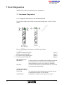
Hardware Diagnostics . . . . . . . . . . . . . .
Diagnostic Indicators on the Controller Board . . . . .
Diagnostic Indicators on Bus Terminal Modules . . . .
Diagnostic Indicators on IBS Devices with I/O Functions .
Diagnostics of IBS Devices from Other Manufacturers . .
Diagnostics with Software Tools. . . . . . . . . . .
The Process Data Monitor Program . . . . . . . . .
The Diagnostic and Configuration Software IBS SYS SWT
The InterBus Manager IBS CMD SWT . . . . . . . .
Diagnostics by the Application Program. . . . . . . .
Diagnostics of Controller Board and Bus Configuration . .
Error Type . . . . . . . . . . . . . . . . . . .
Meanings of Controller Board Error Numbers . . . . .
.
.
.
.
.
.
.
.
.
.
.
.
.
.
.
.
.
.
.
.
.
.
.
.
.
.
7-3
7-3
7-4
7-4
7-5
7-6
7-6
7-6
7-7
7-7
7-7
7-9
7-10
InterBus-S
Table of Contents
Commands for the IBS Master Board . . . . . . . . . . . . . . . . . . . 8-3
8.1
8.2
8.3
8.4
8.5
8.6
8.7
8.8
8.9
.
.
.
.
.
.
.
.
.
.
.
.
.
.
.
.
.
.
.
.
.
.
.
.
.
.
.
.
.
.
.
.
.
.
.
.
.
.
.
.
.
.
.
.
.
.
.
.
.
.
.
.
.
.
.
.
.
.
.
.
.
.
.
.
.
.
.
.
.
.
.
.
.
.
.
.
.
.
.
.
.
8-5
8-6
8-13
8-16
8-19
8-26
8-27
8-28
8-38
.
.
.
.
.
.
.
.
.
nt
ne
m
.
.
.
.
.
.
.
.
.
.
.
.
.
.
.
.
.
.
.
.
.
.
.
.
.
.
.
co
.
.
.
.
.
.
.
.
.
s.
Format of a Message Description
Configuration Messages. . . .
Addressing Messages . . . .
Operation Messages . . . . .
Error Handling Messages . . .
User Interface Messages . . .
System Monitoring Messages .
Process Data Linkage Messages
Event Processing Messages . .
.
.
.
.
.
.
.
.
.
.
.
.
.
.
.
.
.
.
.
.
.
.
.
.
.
.
.
.
.
.
.
.
.
.
.
.
.
.
.
.
.
.
.
.
.
.
.
.
.
.
.
.
.
.
.
.
.
.
.
.
.
.
.
9-5
9-6
9-11
9-14
9-15
9-31
9-32
9-33
9-34
Technical Appendix . . . . . . . . . . . . . . . . . . . . . . . . . . A-3
A.1
Technical Data of the Controller Boards. . . . . . . . . . A-3
in
ec
Document Appendix . . . . . . . . . . . . . . . . . . . . . . . . . . B-3
B.1
B.2
B.3
Figures . . . . . . . . . . . . . . . . . . . . . . B-3
Tables. . . . . . . . . . . . . . . . . . . . . . . B-6
Index . . . . . . . . . . . . . . . . . . . . . . . B-9
on
l
B
.
.
.
.
.
.
.
.
.
Messages of the IBS Master Board . . . . . . . . . . . . . . . . . . . . 9-3
9.1
9.2
9.3
9.4
9.5
9.6
9.7
9.8
9.9
A
.
.
.
.
.
.
.
.
.
po
9
Format of a Command Description.
Configuration Commands . . . .
Addressing Commands . . . . .
Operation Commands . . . . .
Error Handling Commands . . . .
Application Interface Commands .
System Check Commands . . . .
Process Data Linkage Commands .
Event Processing Commands . .
om
8
5036C
Section
1
Introduction and Overview
This section provides:
s.
Quick Start Under DOS . . . . . . .
Programming - Fundamentals . . . .
Documentation . . . . . . . . . .
Modular Design of the Controller Board .
.
.
.
.
.
.
.
.
.
.
.
.
.
.
.
.
.
.
.
.
.
.
.
.
.
.
.
.
.
.
.
.
.
.
.
.
1-3
1-4
1-6
1-8
on
l
in
ec
om
po
ne
1.1
1.2
1.3
1.4
co
Introduction and Overview . . . . . . . . . . . . . . . . . . . . . . . 1-3
nt
1
m
- a short introduction into controller board parameterization and programming;
- a short overview of the documentation available for InterBus-S.
5036C
1-1
1-2
5036C
s.
nt
ne
po
om
in
ec
on
l
co
m
InterBus-S
Introduction and Overview
1 Introduction and Overview
The IBS PC CB/.../I-T controller boards are used to connect InterBus-S to IBMcompatible PCs. The documentation is to provide information on all functionalities and applications. This requires a document size which does not always
make it easy to locate the required information within a short time.
Therefore, we want to give you here a short overview of the controller board
handling. The individual steps are described in detail in the following chapters.
Should you still have questions after studying the manual, call our technical hotline under the phone number Germany: 5235 / 34 18 88.
m
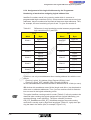
1.1 Quick Start Under DOS
s.
co
The controller board requires 8 bytes in the I/O area of your PC, a free interrupt
and 4 kbytes of free address space. The default settings are so that they often
need not be changed.
ne
nt
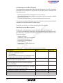
1. Ascertain whether the default settings is right for your PC configuration:
I/O address
120hex
Interrupt
15
Memory address
D000hex
om
po
Always make sure that the settings selected for the controller board are not used
by other components of your PC. For example, the memory area between 640
kbytes and 1 Mbyte is often used by drivers, etc. Select other values if necessary
(see Section 4). Double assignments are the most frequent sources of startup
errors!
on
l
in
ec
2. Remove power from your PC (switch off and remove power cable) and install
the controller board. Be sure that the controller board does not rest on or contact other components in the PC (short-circuit hazard)!
3. Switch on the PC again. The easiest controller board startup method under
DOS is to use the PCCBMONI.EXE monitor program supplied on the tool
diskette (see Section 4).
Before starting the monitor program, be sure to start the driver
IBSPCCB.EXE for the controller board. If you retained the default settings for
your controller board, you do not need to transfer parameters when calling
the driver. The batch file MONI.BAT, which is also on the diskette, provides
an easy way of starting the drivers and the monitor program with one call.
When you have connected a bus configuration, you can check it with the
monitor program without the need to program a single line.
5036C
1-3
InterBus-S
Introduction and Overview
1.2 Programming - Fundamentals
The driver software accesses the controller board’s multi-port memory via a 4
kbyte window in the PC memory area between 640 KB and 1 MB. The following
functions are available for this:
- Functions for opening and closing data channels
- Functions for writing commands and reading messages
(mailbox interface, works with handshake signals and interrupt control features)
- Functions for reading and writing I/O data
(data interface, works without acknowledgment)
- Diagnostic functions for monitoring the controller board’s state
s.
co
m
When opening a data channel, you will receive a node handle in response,
which, similar to the handle in the case of a file access, specifies the data channel and must be entered when data is to be read or written (see driver software
manual IBS PC CB SWD UM E, Order No.: 27 53 96 0).
nt
InterBus-S control
ne
Your application program starts the controller board by means of commands
(e.g. start of the bus system, reading in the bus configuration, see Section 8).
po
After its initialization and the start of the data transmission, the controller board
operates the bus independently and returns messages (see Section 9).
in
ec
om
Section 6 describes the InterBus-specific programming such as
- the physical addressing of the IBS devices,
- the logical addressing of the IBS devices, and
- the combination of the IBS devices into groups
on the basis of a configuration example.
on
l
In the event of a serious error (e.g. interrupted bus cable), all connected IBS
devices automatically go into the RESET state and set their outputs to zero.
Thereupon the controller board examines the error and gives a detailed
description of the error cause and the error location using the
Bus_Error_Information_Indication error message (80C4hex, see Section 9).
1-4
5036C
InterBus-S
Programming - Fundamentals
Program examples
Controller board programming under DOS, Microsoft Windows® and IBM OS/2®
is mainly identical. Thus, programming under DOS can be based without problems on a DOS program example. The driver diskette provides program examples, which already contain the required bus handling. You can fully
concentrate on programming your I/O links.
Training
You will have found that it takes a rather long time to become familiar with all
features of extensive software packages such as Microsoft Winword® or Excel®.
on
l
in
ec
om
po
ne
nt
s.
co
m
The same is true for InterBus-S. Of course you can familiarize yourself easily
with the controller board programming using the documentation and the
supplied example programs. To be able to take full advantage of all their
features, we recommend in addition to attend one of our programming training
courses, where you can acquire an extensive practical knowledge. For the
contents and dates please refer to our seminar brochure, which your local
Phoenix representative will be pleased to send you. On request, we can also
hold a training course, tailored to your particular requirements, on your
premises. Please contact us!
5036C
1-5
InterBus-S
Introduction and Overview
1.3 Documentation
The following documentation is available for the controller boards
- IBS PC CB/I-T,
- IBS PC CB/COP/I-T und
- IBS PC CB/RTX486/I-T:
Description of the hardware
m
This manual (IBS PC CB HW UM E) describes the hardware of the three
controller boards and the InterBus-specific programming. In addition, it includes
a librarary with commands and messages for the IBS master board (firmware
version 3.72).
co
Description of the driver software
nt
s.
The IBS PC CB SWD UM E manual (Order No. 27 53 96 0) describes driver
software for the operating systems DOS, Microsoft Windows® and IBM OS/2®
in connection with various compilers. It is also included in the driver software
package IBS PC CB SWD (Order No. 27 64 70 7)
ne
Description of the developing environment TDOS-PRO
po
(only for IBS PC CB/COP/I-T)
om
The developing environment TDOS-PRO (IBS PC COP SWT, Order No.
27 52 12 3) allows to download a program to the COP386. The relevant documentation is enclosed.
in
ec
Description of the operating system RTXDOS
(only for IBS PC CB/RTX486/I-T)
on
l
The RTX-DOS manual describes the special extensions and features of the
DOS-compatible operating system for the COP486.
Communication via InterBus-S (PCP)
The Peripherals Communication Protocol (PCP) is used for transmitting parameterization data to intelligent IBS devices or for communicating with an IBS device with V24 interface. PCP is a software interface based on the InterBus-S
basic protocol and allows the transmission of non-time-critical large volumes of
data almost independent of the process data.
The IBS PCP UM E manual (Order No. 27 53 93 1) describes the fundamentals
and the application of the Peripherals Communication Protocol.
1-6
5036C
InterBus-S
Documentation
Configuring your InterBus-S system
The configuration manual IBS SYS PRO UM E (Order No. 27 51 00 1) provides
information on the selection of components for your IBS system. It describes the
following features:
- Electrical characteristics (voltage and current ranges)
- Mechanical characteristics (degree of protection, type of connection, installation possibilities, etc.)
- Program characteristics (e.g. required address area in the host)
The manual introduces the design types of the Phoenix Contact product families
available, and their features and ordering data.
m
In addition, a collection of all data sheets available is enclosed.
co
Installing your InterBus-S system
om
po
ne
System overview
Installation of the I/O components
Recommended cabling
I/O startup and function test
Fault clearance
Replacement of IBS components
Cable plans
in
ec
-
nt
s.
Please refer to the installation manual IBS SYS INST UM E (Order No.
27 54 80 4) for installation instructions for I/O components (IBS devices, modules, cables etc.) The manual contains several sections with information on the
following subjects:
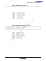
Table 1-1:
Type
Order No.
Controller board system folder:
- Controller board user manual
- Tool diskette
- Manual on the fundamentals and application of the
Peripherals Communication Protocol (PCP)
IBS PC CB UM E
27 54 75 2
Controller board user manual, separate copy
(also included in the system binder)
IBS PC CB HW UM E
27 47 16 7
Driver software manual
(is also supplied with the driver software package
IBS PC CB SWD)
IBS PC CB SWD UM E
27 53 96 0
Manual on the fundamentals and application of the
Peripherals Communication Protocol (PCP), separate
copy (also included in the system binder)
IBS PCP UM E
27 53 93 1
Configuration manual for IBS systems
IBS SYS PRO UM E
27 51 00 1
Installation manual for IBS components
IBS SYS INST UM E
27 54 80 4
on
l
Description
Ordering data for the documents available
Data sheets on new digital and analog I/O modules
5036C
On request
1-7
InterBus-S
Introduction and Overview
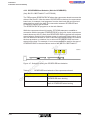
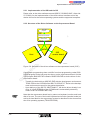
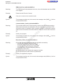
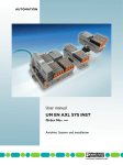
1.4 Modular Design of the Controller Board
2
m
3
5036B202
s.
co
1
nt
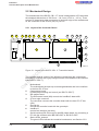
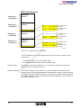
Figure 1-1: Modular design of the controller board
po
ne
The controller boards IBS PC CB/I-T, IBS PC CB/COP/I-T and
IBS PC CB/RTX486/I-T have modular designs and consist of the following components:
om
1 Motherboard
2 IBS master board (MA)
3 Coprocessor board (COP386 or COP486)
in
ec
Only the controller boards IBS PC CB/ COP/I-T and IBS PC CB/RTX486/I-T
have coprocessor boards. On the controller board IBS PC CB I-T it cannot be
retrofitted, as the motherboard does not provide the required interfaces and the
voltage supply.
on
l
The following sections describe the controller board in detail.
1-8
5036C
Section
2
Technical Description of the Motherboard
This section provides information on
po
ne
nt
s.
Short Description . . . . . . . . . . . . . . . . .
Mechanical Design . . . . . . . . . . . . . . . . .
Layout of the Controller Board . . . . . . . . . . . .
Function of the LEDs . . . . . . . . . . . . . . . .
Controller Board Interfaces. . . . . . . . . . . . . .
Connection of the Motherboard with Your PC . . . . . .
Connection Between Motherboard and the Daughterboards .
Interfaces of the IBS Master Board . . . . . . . . . .
Controller Board Functional Units . . . . . . . . . . .
AT Bus Interface. . . . . . . . . . . . . . . . . .
I/O Base Address in the Host . . . . . . . . . . . . .
Multi-Port-Memory . . . . . . . . . . . . . . . . .
MPM Access Method . . . . . . . . . . . . . . . .
Interrupt Functions . . . . . . . . . . . . . . . . .
Voltage Monitoring, Reset System . . . . . . . . . . .
Watchdog for Monitoring the Host PC . . . . . . . . .
Power Supply . . . . . . . . . . . . . . . . . . .
Electrically Isolated IBS Power Supply . . . . . . . . .
.
.
.
.
.
.
.
.
.
.
.
.
.
.
.
.
.
.
2-3
2-4
2-4
2-7
2-8
2-8
2-10
2-10
2-13
2-13
2-13
2-14
2-14
2-15
2-15
2-15
2-16
2-16
on
l
in
ec
2.1
2.2
2.2.1
2.2.2
2.3
2.3.1
2.3.2
2.3.2.1
2.4
2.4.1
2.4.1.1
2.4.2
2.4.2.1
2.4.3
2.4.4
2.4.5
2.4.6
2.4.6.1
co
Technical Description of the Motherboard . . . . . . . . . . . . . . . . . 2-3
om
2
m
- the structure and the components of the motherboard.
5036C
2-1
2-2
5036C
s.
nt
ne
po
om
in
ec
on
l
co
m
InterBus-S
Technical Description of the Motherboard
2 Technical Description of the Motherboard
2.1 Short Description
The IBS PC CB/.../I-T controller boards are used to interface InterBus-S to an
100% IBM-compatible standard PC (AT, 80386, 80486 etc.), which will be
referred to as "host PC" in the following. The controller boards are designed as
plug-in boards for long AT bus slots. The front plate is a common PC board
holder.
co
m
The controller motherboard provides two slots for daughterboards. The first
daughterboard is the IBS master (abbreviated: MA), which is used as an
interface to InterBus-S. As a second daugtherboard, a coprocessor board
(abbreviated: COP) can be used as a fast processor for InterBus-S. The front
plate has two status indicator LEDs for for each daughterboard.
po
ne
nt
s.
The central functional unit of the motherboard is a Multi-Port Memory (MPM)
with an integrated access management. This memory can be accessed from the
host PC and from the two daughterboards, i.e. the MPM has three nodes. The
MPM consists of 64 Kbytes of SRAM with a data word width of 16 bits. It is used
for exchanging commands, messages and data between the two
daughterboards and the host PC. In addition, the motherboard contains the
MPM access control mechanisms.
om
Up to four controller boards can be operated in a host PC. As different board
numbers are set (from 1 to 4) while the I/O address remains the same, the
controller boards differ by an I/O address offset of 0hex, 8hex, 10hex and 18hex,
which depends on the board number.
on
l
in
ec
A controller board occupies 8 bytes in the I/O address area, and a memory
window of 4 Kbytes in the memory area of the host PC. The base address of the
I/O address area can be set with a DIP switch to one of 16 possible addresses.
The base address of the 4Kbyte memory window to the MPM can be set with
the driver software via an I/O address.
A voltage monitoring circuit ensures the operating reliability of the controller
board. In addition to an extensive reset system it is possible to reset each
individual daughterboard by a specific software command. An additional
function for reliability enhancement consists of watchdogs monitoring the
coprocessor board and, via the AT bus, the host PC.
For the interrupt-driven operation of the controller board, the MPM control logic
activates specific interrupt signals for each node. The user can adapt the
interrupt system to the configuration of the host PC.
The motherboard of the IBS PC CB/COP/I-T and IBS PC CB/RTX486/I-T
contains also a battery pack (6V) for backing up the SRAM and the real-time
clock on the coprocessor board.
5036C
2-3
InterBus-S
Technical Description of the Motherboard
2.2 Mechanical Design
The motherboard of the IBS PC CB/.../I-T series is designed as a PC board with
the standards dimensions of 338.5 mm * 114.3 mm (13.33 in. * 4.5 in.). There
are two PC board-style edge connectors at the lower edge of the motherboard
for the connection to the AT bus (ISA) of your PC.
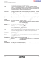
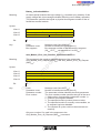
2.2.1 Layout of the Controller Board
22
21 20 19
18
17
16
15
14
13
12
co
m
23
2
9
8
7
ne
nt
s.
3
11 10
5
4
5036C111
om
po
1
6
in
ec
Figure 2-1: Layout of the IBS PC CB/.../I-T controller boards
on
l
The controller boards consist of the following components (the components
identified by numbers with a gray background are not available on the controller
board IBS PC CB/I-T):
1
2
3
4
5
6
7
8
2-4
Motherboard
The motherboard accepts up to two daughterboards and is the interface
to the host PC AT bus.
Coprocessor board
for data preprocessing and control (not IBS PC CB/I-T).
IBS master board
The IBS master board (MA) controls the InterBus-S data traffic.
AT bus edge connector
The connector connects the controller board with the host PC AT bus
(ISA).
Ground pin
Ground the controller board with the ground pin.
InterBus-S
remote bus interface (two-wire)
Serial interface (RS-232 level) for the IBS master board, for connecting a
PC with the software tools IBS CMD SWT or IBS SYS SWT.
Status LEDs, external
The green LEDs indicate the controller board status, see Section 2.2.2.
5036C
InterBus-S
Layout of the Controller Board
9
10
11
12
13
14
20
s.
in
ec
21
nt
19
ne
18
po
17
om
16
co
m
15
Front plate
PC board holder
External reset button
Concealed reset button which can be pressed while the PC housing is
closed.
Reset button jumper
For deactivating the internal and the external reset button
Internal reset button
For convenient operation while the PC housing is open.
Internal IBS master board status LED (green)
For convenient status indication while the PC housing is open.
DIP switch
for setting the base address in the PC’s I/O area and the board number
Jumper, reset (not IBS PC CB/I-T)
For separating the controller board from the PCs hardware reset. This
jumper is used to configure the controller board so that it keeps operating
even when a PC hardware reset has been initiated.
Serial interface (not IBS PC CB/I-T)
RS-232 interface of the coprocessor board
Connector for the RAM back-up battery pack on the coprocessor board
(not IBS PC CB/I-T)
Internal coprocessor board status LED (green, not IBS PC CB/I-T)
For convenient status indication while the PC housing is open.
DIP switch (not IBS PC CB/I-T)
for setting the coprocessor board boot configuration (not IBS PC CB/I-T)
Coprocessor board voltage supply indicator LEDs (not IBS PC CB/I-T)
The green LED indicates that the external supply voltage for the controller
board is applied.
When the red LED is constantly on, the battery pack voltage has fallen
below the permissible minimum value. In this case please replace the
battery pack.
Supply jumper (not IBS PC CB/I-T)
The jumper is used to select whether the controller board is to obtain its
supply voltage from the AT bus or via the terminals for external supply.
Supply terminal (not IBS PC CB/I-T)
Terminal for feeding in the external supply voltage. This terminal is used
to supply the controller board with a voltage (5V DC 1.5A) from an external
power pack.
Battery pack (not IBS PC CB/I-T)
for back-up of the CMOS-SRAM and of the COP real-time clock.
on
l
22
23
5036C
2-5
InterBus-S
Technical Description of the Motherboard
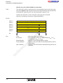
Front plate layout
The front plate (PC board holder) is equipped with two 9-position subminiature
D connectors for the I/O interfaces of the IBS master board. Control elements
are four function LEDs and a reset button, located behind the board holder.
Underneath the subminiature D connector there is a round pin with internal
thread, which can be used for controller board grounding (PE). Figure 2-3 shows
the locations of the components on the PC board holder.
3
RESET
RESET
5
5
nt
s.
6
8
po
om
PE
PE
IBS PC CB/I-T
in
ec
IBS PC CB/COP/I-T
IBS PC CB/RTX486/I-T
6
7
ne
7
8
1
m
4
2
1
co
2
5036C501
on
l
Figure 2-2: Elements on the PC board holder
(green)
External LED MA READY (master board ready)
(green)
External LED MA RUN (InterBus started)
(green)
External LED COP READY (coprocessor board ready)
(green)
External LED COP RUN (coprocessor board active)
External reset button
IBS diagnostic interface (9-position subminiature male connector,
RS232 level)
7 IBS remote bus interface (9-position subminiature D female connector)
8 Ground pin
1
2
3
4
5
6
Ground the controller board with the ground pin.
2-6
5036C
InterBus-S
Function of the LEDs
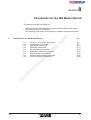
2.2.2 Function of the LEDs
2 LEDs (Figure 2-2) per daughterboard are provided on the front plate (PC
board holder). They indicate the Ready and Run states:
IBS master board
MA READY: After switching on, the IBS master board carried out a boot check
for all functional units including MPM and is ready.
MA RUN:
The IBS master board has started InterBus-S. ID or data cycles
are being transmitted.
co
m
Coprocessor board
(not IBS PC CB/I-T)
COP RUN:
The coprocess board operating system has booted; an application program can be started.
COP READY: A program is running on the coprocessor board.
s.
Coprocessor board booting is followed by the automatic start of various utilities,
some of which remain as TSR programs in the COP memory. Therefore, the
COP READY LED is lit when system startup has been completed.
ne
nt
For convenient observation while the PC housing is open for startup, the LEDs
are provided once more at the board edge opposite the AT bus.
po
There are two 8-way DIP switches at the top edge of the controller board for the
setting of the I/O board address and the board number, and for the power-up
configuration. They are easy to operate even in the built-in condition.
on
l
in
ec
om
The settings of the DIP switches are only read in when the controller board
boots. After the setting has been changed, the controller board must be reset to
make the change effective.
5036C
2-7
InterBus-S
Technical Description of the Motherboard
2.3 Controller Board Interfaces
The following sections describe the various controller board interfaces.
2.3.1 Connection of the Motherboard with Your PC
The AT bus edge connectors connect the controller board with the AT bus of the
host PC. The signal assignment is compatible with the ISA standard; the
controller board requires only a data bus width of 8 bits.
om
in
ec
Key:
I = Input
O = Output
B = Bidirectional
M = For measuring only
2-8
co
I, T, PD100
I, T, PD100
I, T, PD100
I, T, PD100
Signal
Function
IRQ10
IRQ11
IRQ12
IRQ15
O, C, TS
O, C, TS
O, C, TS
O, C, TS
+5 V
SV
GND
SV
s.
LA23
LA22
LA21
LA20
Pin
D1
D2
D3
D4
D5
D6
D7
D8
D9
D10
D11
D12
D13
D14
D15
D16
D17
D18
nt
Function
po
Signal
on
l
Pin
C1
C2
C3
C4
C5
C6
C7
C8
C9
C10
C11
C12
C13
C14
C15
C16
C17
C18
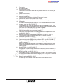
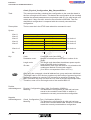
Pin assignment of the short AT bus edge connector
ne
Table 2-1:
m
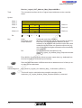
Tables 2-1 and 2-2 show the pin assignments of the edge connectors to the AT
bus. The interface signals are exclusively standardized AT bus signals.
SV = Supply voltage
T = TTL level
C = CMOS level
OC = Open collector
TS = Tristate
PU ... = Pullup ... [kΩ]
PD ... = Pulldown ... [kΩ]
UN ... = Nominal voltage[V]
5036C
InterBus-S
Connection of the Motherboard with Your PC
om
in
ec
Key:
I = Input
O = Output
B = Bidirectional
M = For measuring only
5036C
Function
V
I, T
SV
O, C, T, S
+12 V
GND
SMEMWL
SMEMRL
IOWL
IORL
SV
SV
I, T
I, T
I, T
I, T
REFRESHL
I, T
IRQ7
O, C, TS
IRQ5
O, C, TS
IRQ3
O, C, TS
BALE
+5 V
OSC
GND
I, T
SV
I, T
SV
m
Signal
GND
RESET
+5 V
IRQ2/9
co
B, T, TS
B, T, TS
B, T, TS
B, T, TS
B, T, TS
B, T, TS
B, T, TS
B, T, TS
O, C, PU10
I, T
I, T
I, T
I, T
I, T
I, T
I, T
I, T
I, T
I, T
I, T
I, T
I, T
I, T
I, T
I, T
I, T
I, T
I, T
I, T
I, T
s.
SD7
SD6
SD5
SD4
SD3
SD2
SD1
SD0
IOCHRDY
AEN
SA19
SA18
SA17
SA16
SA15
SA14
SA13
SA12
SA11
SA10
SA9
SA8
SA7
SA6
SA5
SA4
SA3
SA2
SA1
SA0
Pin
B1
B2
B3
B4
B5
B6
B7
B8
B9
B10
B11
B12
B13
B14
B15
B16
B17
B18
B19
B20
B21
B22
B23
B24
B25
B26
B27
B28
B29
B30
B31
nt
Function
po
Signal
on
l
Pin
A1
A2
A3
A4
A5
A6
A7
A8
A9
A10
A11
A12
A13
A14
A15
A16
A17
A18
A19
A20
A21
A22
A23
A24
A25
A26
A27
A28
A29
A30
A31
Pin assignment of the long AT bus edge connector
ne
Table 2-2:
SV = Supply voltage
T = TTL level
C = CMOS level
OC = Open collector
TS = Tristate
PU ... = Pullup ... [kΩ]
PD ... = Pulldown ... [kΩ]
UN ... = Nominal voltage[V]
2-9
InterBus-S
Technical Description of the Motherboard
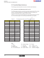
2.3.2 Connection Between Motherboard and the Daughterboards
Two 58-position female connectors for the master board and two for the
coprocessor board provide the connection between the motherboard and these
two daughterboards. Both interfaces are assigned in the same way the address,
data and control lines of the Multi-Port Memory (MPM) and slot-specific MPM
signals. In addition, the signals of any I/O interfaces are supplied to the
connectors of both interfaces. They are divided into the I/O signals, which are at
system potential, and the electrically isolated IBS signals.
2.3.2.1 Interfaces of the IBS Master Board
co
m
The IBS master board has two interfaces, the signals of which are supplied via
the 58-position female connectors to the motherboard connectors described
below.
Diagnostic interface (serial)
ne
nt
s.
An IBM-compatible PC with the software IBS SYS SWT or IBS CMD SWT can
be connected as a diagnostic device via the diagnostic interface (RS-232 level).
The diagnostic interface connector on the front plate is a 9-position male
subminiature D connector.
om
po
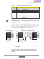
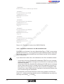
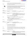
The diagnostic cable IBS PRG CAB (Order No. 28 06 86 2) as shown below
connects the diagnostic interface with the IBM-compatible PC.
Front plate
RXD
TXD
GND
RTS
CTS
on
l
in
ec
2
3
5
7
8
Pin side
Diagnostic cable
Solder
side
5
9
5
1
6
1
SUB-D 9-position
male
9
6
RXD 2
TXD
GND
RTS
CTS
3
5
7
8
SUB-D 9-position
female
2
3
5
7
8
Solder
side
RXD
TXD
GND
RTS
CTS
6
9
1
5
SUB-D 9-position
female
5036D203
Figure 2-3: Diagnostic interface and diagnostic cable for the connection of a PC
2-10
5036C
InterBus-S
Interfaces of the IBS Master Board
Table 2-3:
Pin assignment of the diagnostic interface
Signal
RXD
TXD
GND
RTS
CTS
-
Function
Reserved
Received Data
Transmitted Data
Reserved
Digital Ground
Reserved
Request to Send (not firmware-supported)
Clear to Send (not firmware-supported)
Reserved
co
m
Pin
1
2
3
4
5
6
7
8
9
s.
Connecting the controller board with a diagnostic PC requires only the signals
TXD, RXD and GND.
nt
Remote Bus Interface
po
ne
The remote bus interface is used to connect the remote bus (2-wire) of the IBS
system. It is accessible on the front plate as a 9-position subminiature D female
connector and electrically isolated from the host potential. The connector
housing is conductively connected with the PC board holder.
1
6
1
6
5
9
5
9
SUB-D 9-pos.
female
Remote bus cable (D9/D9)
DO
DO
DI
DI
COM
Strain
relief
SUB-D 9-pos.
male
6
1
7
2
3
5
9
green
yellow
pink
gray
brown
bridged
in
ec
6
1
7
2
3
5
9
Solder
side
Socket
side
on
l
DO
DO
DI
DI
COM
+5V
RBST
om
Front plate
6 DO
1 DO
7 DI
2 DI
3 COM
Strain
relief
Solder
side
6
1
9
5
SUB-D 9-pos.
female
5036C204
Figure 2-4: Remote bus interface and example of a remote bus cable (cable
type D9/D9)
The bridge between pin 5 and pin 9 indicates to the outgoing remote bus
interface of an IBS device that the outgoing remote bus cable has been
connected.
5036C
2-11
InterBus-S
Technical Description of the Motherboard
Table 2-4:
Remote bus interface pin assignment
Signal
DO
DI
COM
Reserved
+5 V
DO
DI
Reserved
RBST
co
m
Pin
1
2
3
4
5
6
7
8
9
on
l
in
ec
om
po
ne
nt
s.
For detailed information on the cable specification, all IBS cable types and the
installation of your IBS system please refer to the installation manual
IBS SYS INST UM E (Order No. 27 54 80 4).
Figure 2-5: Workmanlike connection of a remote bus connector
(subminiature D 9)
Connect the connector as follows:
1 Cut off 20 mm (0.79 in.) of the cable sheath and 12 mm (0.47 in.) of the shield
braid.
2 Strip off 3 mm (0.12 in.) of the wire ends, and fold the shield braid evenly back
onto the cable sheath.
3 After soldering on the wire ends, clamp a large surface of the shield braid,
2-12
5036C
InterBus-S
Controller Board Functional Units
which now lies on the cable sheath, under the conductive strain relief.
For fault-free InterBus-S operation, the remote bus cable shield braid must be
connected to PE on the controller board. Use only subminiature D connectors
with metal-plated or metal housings. Always ensure that a large surface of the
remote bus cable shield braid is in contact with the conductive strain relief
conductively connected with the connector shell. Ground the controller board via
the ground pin (Figure 2-2).
2.4 Controller Board Functional Units
m
2.4.1 AT Bus Interface
ne
nt
s.
co
The AT bus interface has an 8-bit data bus and a 24-bit address bus. Besides
data, address and control line buffering, it comprises the address decoding
feature and the setting facilities for the 8-byte I/O address area and the 4 Kbyte
memory window to the MPM. In addition, interrupt signals from the MPM control
logic are supplied to the AT bus for the communication with the daughterboards
via the MPM. They can be switched to the interrupt inputs of the PC. The
functionality of the AT bus interface is described in the following.
po
2.4.1.1 I/O Base Address in the Host
in
ec
om
For each controller board, an I/O address area of 8 bytes is required for the
status register, the mapping register and the control ports. Using a DIP switch,
the base address of this address area can be set to one of sixteen possible
addresses; it must be defined before the controller board start-up. Take care to
avoid address conflicts with other boards of the host PC. The base addresses
that can be set and the corresponding DIP switch setting on the motherboard
are specified in Section 5.
on
l
The AT bus interface is so designed that four controller boards can share an
I/O base address of the host PC. The four controller boards are then, depending
on a board number (1 to 4) that can be set with a DIP switch, addressed with an
offset of 0hex, 8hex, 10hex and 18hex relative to the base address. Section 5
shows the relationship between the board number and the offset to the base
address that has been set, and the corresponding DIP switch setting.
5036C
2-13
InterBus-S
Technical Description of the Motherboard
2.4.2 Multi-Port-Memory
The Multi-Port-Memory (MPM) of the controller boards is used for exchanging
data between the host PC and the two daughterboards. The MPM is a static
RAM (SRAM) and has a storage capacity of 64 Kbytes.
Please note the following when accessing the MPM: The IBS master board uses
the Motorola format (68xxx family) when placing its data in the MPM, whereas
the host processor and the COP processor expect data always in the Intel
format. These two formats use opposite orders of addressing the bytes in a data
word. For MPM acess use the supplied macros, which exchange the high byte
and the low byte when accessing the data word (see the Driver Software Manual
IBS PC CB SWD UM E).
co
m
The MPM contains the mailbox interface (MXI) for commands and messages,
and the data interface (DTI) for process data. In addition, several hardware
registers are mapped to the MPM address area. They are used for exchanging
status and handshaking information.
ne
2.4.2.1 MPM Access Method
nt
s.
Each node has its own memory areas in the MPM. Every node may write to its
own area, but may only read from the areas of the other nodes.
po
As the nodes can access the MPM completely asynchronously, the following
access conflicts could occur:
in
ec
om
- Simultaneous or overlapping reading to/writing from the same memory
location,
- Reading from a logically coherent data area by a node, while this area is
being written to by another node.
on
l
The first type of conflict is prevented by circuitry measures in the MPM access
management. In the event of simultaneous access, the order of priorities is:
- Priority 1: host PC
- Priority 2: daughterboard 1 (IBS master)
- Priority 3: daughterboard 2 (coprocessor board)
When access operations overlap, the current access is first completed.
The second type of conflict is solved by the fact that the number of successive
byte accesses per data transfer can be set variably. The MPM control logic
provides data consistencies of 8, 16, 32 and 48 bits. The MPM access
management inhibits MPM accesses by the other nodes until the last byte
access of a data transfer has been completed.
In the event of an access conflict in the MPM, a node is stopped by a ready
signal until the other node has completed its access. The access by a node is
not completed before it has fetched all data bytes according to the data
consistency setting.Byte access by one MPM data transfer must be carried out
in direct succession, as the MPM control logic cancels the MPM access
inhibition feature after a certain time (timeout). The driver software functions
automatically allow for this; so you do not need to take any special precautions
2-14
5036C
InterBus-S
Interrupt Functions
in your application program.
2.4.3 Interrupt Functions
Access methods with different access protocols are defined between the MPM
nodes. The MPM hardware supports the protocols with handshake interrupts. In
addition, each node interface has an interrupt line indicating the system failure
of one of the nodes. Both daughterboards can interrupt the host PC by means
of the host interrupt.
2.4.4 Voltage Monitoring, Reset System
s.
co
m
The reliable operation of the IBS controller board requires a sufficient operating
voltage supply (5V) via the AT bus. When the supply falls short of the minimum
voltage, an integrated voltage monitoring feature triggers a reset of the IBS
controller board. This prevents malfunctions on the InterBus-S due to undefined
conditions while the controller board is switched on/off, and due to voltage dips.
A reset of the controller board is triggered when the following conditions are met:
po
ne
nt
- The voltage monitoring circuitry trips
- Reset signal on the AT bus (can be disabled for IBS PC CB/COP/I-T and
IBS PC CB/RTX486/I-T, see Figure 2-1, item 15)
- Operation of the reset button on the front plate (PC card holder) or of the reset
button at the upper edge of the controller board
in
ec
om
To prevent an unintentional operation of the reset button on the front plate, it is
located in a concealed position (see Figure 2-2). Both buttons can also be
disabled by removing a jumper (see Figure 2-1).
Table 2-5:
Function of the jumper for the reset button
on
l
Jumper S105
Installed
Not installed
Reset button
enabled
disabled
This reset affects the following functional units:
- the AT bus interface of the controller board
- the MPM control logic
- the two daughterboards
The daughterboards can also be reset separately by the software.
2.4.5 Watchdog for Monitoring the Host PC
While the daughterboards have their own watchdog circuits for monitoring their
operation, a watchdog for monitoring the host PC was incorporated into the AT
bus interface on the IBS controller motherboard. The operation of the watchdog
is described in detail in Section 4.
5036C
2-15
InterBus-S
Technical Description of the Motherboard
2.4.6 Power Supply
The controller board is supplied with power from the 5V system voltage of the
PC, via the edge connectors. With certain flash EPROM types on the
coprocessor board, the 12V supply of the AT bus is required for programming
the flash EPROMs (current consumption: approx. 40mA).
2.4.6.1 Electrically Isolated IBS Power Supply
m
The driver components require an isolated power supply for the electrically
isolated operation of InterBus-S. The motherboard is equipped with a DC/DC
converter, which generates this voltage from the 5V system voltage of the PC.
It provides an output voltage of 5 V at a maximum current of 200mA, which is
capacitively coupled to PE for reasons of noise elimination.
on
l
in
ec
om
po
ne
nt
s.
co
Ground the controller board via the ground pin (Figure 2-2).
2-16
5036C
Section
3
Technical Description of the Coprocessor Boards
Only for IBS PC CB/COP/I-T and IBS PC CB/RTX486/I-T.
This section provides information on
po
ne
nt
s.
Short Description . . . . . . . . .
Mechanical Design . . . . . . . . .
Coprocessor Board Interfaces . . . .
Motherboard Interface . . . . . . .
Serial Interface . . . . . . . . . .
Coprocessor Board Functional Units . .
Processor/Chipset . . . . . . . . .
Chipset Components . . . . . . . .
Coprocessor Board I/O Address Area .
Coprocessor Board Interrupt Assignment
Coprocessor Board Memory . . . . .
EPROM . . . . . . . . . . . . .
Static RAM . . . . . . . . . . . .
Dynamic RAM. . . . . . . . . . .
MPM Interface . . . . . . . . . .
Mapping Register . . . . . . . . .
Coprocessor Board Serial Interface . .
Coprocessor Board Security Units . . .
Coprocessor Board Voltage Monitoring .
Coprocessor Board Reset System . . .
Coprocessor Board Watchdog . . . .
Coprocessor Board Real-time Clock . .
Coprocessor Board Power Supply . . .
Battery Back-up . . . . . . . . . .
on
l
in
ec
3.1
3.2
3.3
3.3.1
3.3.2
3.4
3.4.1
3.4.1.1
3.4.1.2
3.4.1.3
3.4.2
3.4.2.1
3.4.2.2
3.4.2.3
3.4.3
3.4.4
3.4.5
3.4.6
3.4.6.1
3.4.6.2
3.4.6.3
3.4.7
3.4.8
3.4.8.1
co
Technical Description of the Coprocessor Boards . . . . . . . . . . . . . 3-3
om
3
m
- the structure and the components of the coprocessor board.
5036C
.
.
.
.
.
.
.
.
.
.
.
.
.
.
.
.
.
.
.
.
.
.
.
.
.
.
.
.
.
.
.
.
.
.
.
.
.
.
.
.
.
.
.
.
.
.
.
.
.
.
.
.
.
.
.
.
.
.
.
.
.
.
.
.
.
.
.
.
.
.
.
.
.
.
.
.
.
.
.
.
.
.
.
.
.
.
.
.
.
.
.
.
.
.
.
.
.
.
.
.
.
.
.
.
.
.
.
.
.
.
.
.
.
.
.
.
.
.
.
.
.
.
.
.
.
.
.
.
.
.
.
.
.
.
.
.
.
.
.
.
.
.
.
.
.
.
.
.
.
.
.
.
.
.
.
.
.
.
.
.
.
.
.
.
.
.
.
.
.
.
.
.
.
.
.
.
.
.
.
.
.
.
.
.
.
.
.
.
.
.
.
.
.
.
.
.
.
.
.
.
.
.
.
.
.
.
.
.
.
.
.
.
.
.
.
.
3-3
3-5
3-6
3-6
3-6
3-8
3-8
3-9
3-9
3-10
3-10
3-10
3-11
3-11
3-13
3-14
3-14
3-14
3-14
3-14
3-14
3-15
3-15
3-16
3-1
3-2
5036C
s.
nt
ne
po
om
in
ec
on
l
co
m
InterBus-S
Technical Description of the Coprocessor Boards
3 Technical Description of the Coprocessor Boards
(for IBS PC CB/COP/I-T and IBS PC CB/RTX486/I-T)
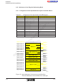
3.1 Short Description
The coprocessor boards (abbreviated: COP) are industrial PCs optimized for
control tasks, in the form of daughterboards for the controller motherboards
IBS PC CB/COP/I-T and IBS PC CB/RTX486/I-T.
Table 3-1:
Overview of coprocessor boards
IBS PC CB/RTX486/I-T
Coprocessor board
COP386
COP486
CPU
386SX-25, MHz
486 SXLC-40, 40 MHz double clock, 8
Kbytes of cache
Main memory
2 Mbytes
2 Mbytes
Static RAM
(battery backedup)
128 Kbytes
128 Kbytes
- as RAM disk (D:\)
EPROM 1
128 Kbytes of EPROM for
operating system
EPROM 2
-
in
ec
om
po
ne
nt
s.
co
m
IBS PC CB/COP/I-T
256 Kbytes of flash EPROM:
- 128 Kbytes for operating system
- 128 Kbytes for device driver and
application
256 Kbytes of flash EPROM for application
TDOS
RTXDOS
Access from the
PC via
Development environment TDOS-PRO*
Terminal program DPCON.EXE (is on the
tool diskette)
on
l
Operating system
* The development environment TDOS-PRO (IBS PC COP SWT) is not compatible with the COP486 of the IBS PC CB/RTX486/I-T, nor is it required for
it.
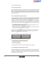
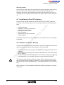
This coprocessor board is used to relieve the host PC processor of some of its
tasks; this contributes to considerable performance gains of the PC system.
The central functional unit of the COP is an Intel-compatible microprocessor.
The coprocessor board is accessed either via the Multi-Port Memory (MPM) or
via a PC-compatible serial interface. The coprocessor boards are essentially
PC-compatible (with the exception of the keyboard, the monitor and the hard
disks), which allows programming with standard tools such as Turbo Pascal or
Turbo C. The 2 Mbyte main memory provides enough space even for extensive
software projects. The coprocessor board ensures the unrestricted use of the
EMS features familiar from PCs.
128 Kbytes of battery-backed-up static RAM (SRAM), and, on the COP486, ad-
5036C
3-3
InterBus-S
Technical Description of the Coprocessor Boards
ditional 384 Kbytes of flash EPROM (128 Kbytes in flash EPROM 1 and 256
Kbytes in flash EPROM 2) are available for long-term storage of information or
programs. The flash EPROM contains also the operating system (T-DOS) of the
coprocessor board.
The coprocessor board operating system also is in flash EPROM 1.
The coprocessor board incorporates a quartz-controlled real-time clock (PCcompatible) for time-dependent control of machines via InterBus-S.
m
To ensure a high degree of data integrity in industrial applications, the coprocessor boards feature a sophisticated watchdog and reset circuitry. It enables the
user to detect system errors at an early stage and to shut down equipment if necessary. After the protective mechanism has been enabled, the coprocessor
boards are able to restart the application program by themselves.
s.
co
The interrupt control feature on the coprocessor board informs other MPM
nodes (host PC, IBS master) about any functional errors. Two LEDs on the front
plate of the motherboard provide visual information on the status of the
coprocessor board.
po
ne
nt
The TDOS and RTXDOS operating systems (DOS-compatible) provide a software basis which is specially adapted to the requirements of the coprocessor
boards. This makes it possible to implement existing DOS applications on the
coprocessor board. For real-time applications, additional real-time multitasking
operating systems may be used (on request).
in
ec
om
In the software development stage, the data transmission between the operating
system TDOS of the COP386 and the development tool TDOS-PRO (IBS PC
COP SWT, Order No. 27 52 12 3) can be effected via the MPM or the serial interface of the COP.
on
l
Using the RFSERVER.EXE program, which is to be started directly on the host,
the operating system RTXDOS of the COP486 can directly access the host
mass storage units (floppy drives, hard disks). RFSERVER.EXE is on the diskette supplied with this manual.
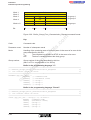
Table 3-2: COP 486 drives
Drive
Data carrier
Use
A:\
128 Kbytes in flash EPROM1
Device drivers and application
programs
B:\
—
Not used
C:\
256 Kbytes in flash EPROM2
Application programs
D:\
128 Kbytes of static RAM (battery-backed-up)
Application programs, data
E:\
Drive C:\ of the PC (host hard disk)
Application programs, data
3-4
5036C
InterBus-S
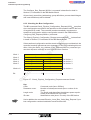
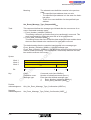
Mechanical Design
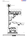
EPROM 1
128K x 8
(COP386)
256K x 8
(COP486)
EPROM 2
256K x 8
(COP486)
co
m
Memory
mapper
D RAM
128K x 8
ne
nt
s.
2 MB x 8
S RAM
po
CPU
SCATsx
om
386SX-25
(COP386)
S BUS
X BUS
82C836
Motherboard
interface
on
l
in
ec
486SXLC-40
(COP486)
MPM
interface
Voltage
monitoring
UART
Watchdog
16C450
Serial
interface
5036C301
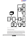
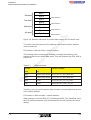
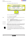
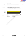
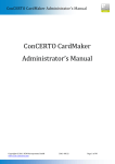
Figure 3-1: Coprocessor board block diagram
3.2 Mechanical Design
For the connection with the motherboard, the coprocessor board (COP) has a
58-position male connector on each side. The correct orientation for the installation of the COP results from the asymmetrically located drill holes (one on the
coprocessor board and one on the motherboard). On the underside of the COP
there is a four-position connector for the connection of a commercially available
PC battery pack, and a 10-position connector for the serial interface.
5036C
3-5
InterBus-S
Technical Description of the Coprocessor Boards
To achieve a high flexibility of the COP, a feature for performing configurations
via DIP switches or jumpers has not been implemented. The hardware-specific
settings are automatically performed by the driver software.
3.3 Coprocessor Board Interfaces
This section describes the various coprocessor board interfaces and their signal
assignment.
3.3.1 Motherboard Interface
m
Functions of the interface:
3.3.2 Serial Interface
ne
nt
s.
co
- Data exchange between the motherboard and the coprocessor board. The
data width is 16 bits. All data and address lines are buffered.
- Supply of control signals: interrupt control signals, write and read control, reset and watchdog control.
- Supply and special lines: voltage supply, battery back-up, LED control,
RS-232 interface.
om
po
The coprocessor board has a serial interface (RS-232 level), which corresponds
to the COM 1 of a standard PC, and which you can use, for example, for the following applications:
on
l
in
ec
- If the development environment TDOS-PRO (IBS PC COP SWT) is not to
access the COP386 by way of the MPM. For more detailed information refer
to the manual for the development environment TDOS-PRO, which is supplied with the software.
- For remote debugging (e.g.: with Turbo/Borland C remote debugger). Please
refer to the manual of your compiler for more detailed information.
- Own applications
Adapter cable IBS PC COP RS 232 CAB
This fully PC-compatible interface is implemented as a 10-position male connector on the edge of the coprocessor board. It can be connected to a subminiature
D connector using the adapter cable IBS PC COP RS232 CAB. Mount the subminiature D connector on, for example, an additional PC board holder (free slot).
The adapter cable is available under Order No. 27 51 65 8. It is also supplied
with the development environment TDOS-PRO (IBS PC COP SWT).
The female connector of this adapter cable is identified by a polarizing bump
next to pin 5.
- If the 10-position male connector is located in a polarized connector shell,
install the female connector in the shell so that the polarizing bump faces the
motherboard (see Figure 3-2).
- If you have an earlier coprocessor board without a polarized connector shell,
mount the female connector on the shell so that the bump faces the copro-
3-6
5036C
InterBus-S
Serial Interface
cessor board (rotated by 180° compared with the drawing in Figure 3-2).
2 4 6 8 10
1357 9
5036C508
co
m
Figure 3-2: Pin arrangement in the COP connector shell
Table 3-3: Adapter cable assignment
s.
Function
Signal
ne
nt
Coprocessor board
pin assignment
Subminiature
D9
pin assignment
Data Carrier Detect (input)
DCD
1
2
Data Set Ready (input)
DSR
6
3
Received Data (input)
RXD
2
4
Request To Send (output)
RTS
7
5
Transmitted Data (output)
TXD
3
6
Clear To Send (input)
CTS
8
Data Terminal Ready (output)
DTR
4
RI
9
GND
5
-
-
om
Ring Indicator (input)
on
l
8
in
ec
7
po
1
9
Signal Ground
10
Unused
Development cable
The connection of the serial interface (subminiature D connector) of the
COP386 and of the PC on which the development environment
IBS PC COP SWT (TDOS-PRO) is running is effected with a development cable
(zero modem cable) as shown below.
5036C
3-7
InterBus-S
Technical Description of the Coprocessor Boards
Additional
PC board holder
2
3
5
7
8
Pin side
Development cable
Soldering
side
RXD
TXD
RXD
5
5
9
9
GND
RTS
TXD
GND
1
1
6
6
CTS
RTS
CTS
2
3
5
7
8
2
3
5
7
8
RXD
TXD
6
1
GND
RTS
9
5
CTS
SUB-D 9-pole
sockets
SUB-D 9-pole
female
SUB-D 9-pos.
male
Soldering
side
co
Figure 3-3: Development cable for the COP386
m
5036C302
nt
s.
The development cable is supplied with the development environment TDOSPRO (IBS PC CB COP SWT, Order No. 27 52 12 3).
ne
3.4 Coprocessor Board Functional Units
om
Processor/chipset
Memory (DRAM; SRAM; EPROM)
MPM interface (Multi-Port Memory)
Memory mapper
Serial interface (UART)
Voltage monitoring and reset system
Power supply
in
ec
-
po
The functionality of the coprocessor board is divided into seven main functional
elements:
on
l
The following sections describe these funtional units, their settings and
meanings in detail.
3.4.1 Processor/Chipset
The processor core is a 386SX-25 for the COP386 and a 486SXLC40 microprocessor for the COP486, both in connection with the single-chipset 82C836.
3-8
5036C
InterBus-S
Chipset Components
3.4.1.1 Chipset Components
The 82C836 component is a highly integrated single-chip AT chipset. It contains
all circuitry components required for a PC, such as:
one 146818-compatible real-time clock with 114 bytes of CMOS-RAM
two 8237-compatible DMA controllers
two 8259-compatible interrupt controllers
one 8254-compatible counter/timer
one 82284-compatible clock generator and ready interface
one 82288-compatible bus controller
one DRAM controller / DRAM refresh controller
four EMS page registers (LIM EMS 4.0 and 3.2)
co
3.4.1.2 Coprocessor Board I/O Address Area
m
-
Table 3-4:
I/O address area of the coprocessor board
Function:
om
I/O address:
03C0hex
po
ne
nt
s.
Besides the usual standard addresses of the IBM PC, the I/O address area of
the coprocessor board has some additional special functions. Various watchdog
functions are enabled in the address area from 200hex to 2BFhex (according to
IBM reserved for the prototype board). The address area from 280 hex to 2BFhex
contains the mapping register (a register for controlling controller-specific memory functions) including some bits for special functions such as for watchdog
control.
to
03FFhex
Area for the COM1 serial interface
to
03BFhex
Unused
to
033Fhex
Watchdog Clear
02C0hex
to
02FFhex
Unused
0280hex
to
2BFFhex
Mapping register
0240hex
to
027Fhex
Watchdog enable
0200hex
to
023Fhex
Watchdog trigger
00E0hex
to
01FFhex
Unused
00C0hex
to
00DFhex
DMA controller 2
00A0hex
to
00BFhex
Interrupt controller 2 (Slave)
0080hex
to
009Fhex
DMA page register / NMI mask
0070hex
to
007Fhex
Real-time clock
0060hex
to
006Fhex
System register
0040hex
to
005Fhex
Timer / counter
0020hex
to
003Fhex
Interrupt controller 1 (master)
0000hex
to
001Fhex
DMA controller 1
0340hex
on
l
in
ec
0300hex
The base address for the serial interface COM2 is, as usual for IBM-compatible
PCs, at the address 03F8hex.
5036C
3-9
InterBus-S
Technical Description of the Coprocessor Boards
3.4.1.3 Coprocessor Board Interrupt Assignment
The interrupt system is also mainly identical to the usual standard of an IBM PC.
For the communication with the MPM a so-called handshake interrupt is used,
which has the interrupt number 5. In the event of a system error of another MPM
node (host PC, IBS master), a non-maskable interrupt (NMI) is triggered on the
coprocessor board. When, however, an error occurs on the coprocessor board,
an interrupt signal to the other nodes is generated if the watchdog is enabled.
This signal is fed to the mother board interface and is referred to as SRQ2L. The
following table outlines the interrupt assignment of the coprocessor board.
Table 3-5:
Interrupt
Interrupt assignment of the coprocessor board
Function
Timer channel 0
IRQ1
Unused
IRQ2
Slave interrupt controller
IRQ3
Unused
IRQ4
COM1
IRQ5
Handshake interrupt MPM
IRQ6
Timer channel 2
IRQ7
Unused
po
Unused
Unused
in
ec
om
IRQ10
IRQ13
co
Real-time clock
IRQ9
IRQ12
s.
nt
ne
IRQ8
IRQ11
m
IRQ0
Unused
Unused
Unused
Unused
IRQ15
Unused
on
l
IRQ14
3.4.2 Coprocessor Board Memory
The memory segmentation is as follows:
- 128 Kbytes of static RAM (SRAM), battery-backed-up with a data width of 8
bits
- 2 Mbytes of DRAM with a data width of 16 bits
3.4.2.1 EPROM
Two 32-position PLCC EPROM sockets for 128 Kbyte or 256 Kbyte EPROMs or
flash EPROMs are provided on the coprocessor board.
IBS PC CB/COP/I-T
On delivery, socket 1 is equipped with a 128 Kbyte EPROM for the operating
system. Socket 2 is not fitted with an EPROM.
3-10
5036C
InterBus-S
Static RAM
IBS PC CB/RTX486/I-T
On delivery, socket 1 and socket 1 are equipped with 256 Kbytes of flash
EPROM each.
3.4.2.2 Static RAM
128 Kbytes of static RAM (SRAM) are available on the coprocessor board for
storing data (e.g. equipment states). This memory is battery-backed and has a
width of 8 bits.
IBS PC CB/COP/I-T
s.
co
m
The SRAM on the COP386 can be addressed via the memory segment
B0000hex in two 64 Kbyte blocks. The access is via driver software functions.
ne
nt
RAM
po
BFFFFhex
in
ec
om
B0000 hex
64
Kbyte
SRAM
SRAM
64 Kbyte
SRAM
1FFFFhex
10000 hex
BFFFFhex
00000 hex
5036A304
on
l
Figure 3-4: SRAM segmentation on the COP386 of the IBS PC CB/COP/I-T
IBS PC CB/RTX486/I-T
The SRAM on the COP486 is accessed as drive D:\ and, therefore, can be used
as RAM disk by means of usual DOS functions.
The program RDRCONF.EXE is used to parameterize the type of access to the
SRAM of the COP486. You can, for example, also set the addressing described
for the COP386 in two 64 Kbyte blocks. This manual comes complete with
RDRCONF.EXE.
3.4.2.3 Dynamic RAM
The coprocessor board contains 2 Mbytes of dynamic RAM (DRAM) as main
memory. The main memory is operated with 0 RAM wait states and in the page
interleave mode, which increases the processing speed.
5036C
3-11
InterBus-S
Technical Description of the Coprocessor Boards
As the coprocessor board works in the real mode because there is no keyboard
controller, the use of the second megabyte (100000hex to 1FFFFFhex) is only
possible when the EMS functions are used. For this purpose there is an EMS
driver on the tool diskette.
Table 3-6: DRAM segmentation
Megabyte
Allocation
Supplement
100000hex
to
1FFFFFhex
10 to 1F
0F0000hex
to
0FFFFFhex
F
0E0000hex
to
0EFFFFhex
E
0D0000hex
to
0DFFFFhex
D
0C0000hex
to
0CFFFFhex
C
0B0000hex
to
0BFFFFhex
B
0A0000hex
to
0AFFFFhex
A
090000hex
to
09FFFFhex
9
080000hex
to
08FFFFhex
8
070000hex
to
07FFFFhex
7
060000hex
to
06FFFFhex
6
050000hex
to
05FFFFhex
040000hex
to
04FFFFhex
030000hex
to
03FFFFhex
3
020000hex
to
02FFFFhex
2
010000hex
to
01FFFFhex
1
Main memory
000000hex
to
00FFFFhex
0
TDOS system area
XMS/EMS memory
reserved
s.
co
m
Mapping window
nt
5
Bios
DRAM
Main memory/
download RAM
DRAM
4
ne
po
1.
Bank
om
2.
Adress area
in
ec
The 4 Kbyte memory area from B0000hex to BFFFFhex is configured as a mapping window, via which the driver software functions access the MPM, the static
RAM and the EEPROMs.
on
l
Do not directly access the coprocessor board DRAM in the area of the mapping
window!
The driver software functions select via the mapping register in the I/O area of
the coprocessor board which memory is mapped via the mapping window.
3-12
5036C
InterBus-S
MPM Interface
3.4.3 MPM Interface
Host
m
MPM
Coprocessor
board
nt
s.
co
IBS
master board
ne
IBS PC CB/COP/I-T
5036C205
po
Figure 3-5: The MPM as the central interface
in
ec
om
The MPM is the central interface between the host PC, IBS master (MA) and
coprocessor board (COP). To ensure a problem-free communication between
the MPM nodes, all data and address lines of the COP are buffered. The buffers
are only enabled when the coprocessor board is granted the right of access. The
right of access is granted by a priority control feature in the MPM logic (on the
motherboard). After the MPM request by the coprocessor board and before the
motherboard grants the right of access, the COP processor is in the Halt state.
on
l
When the coprocessor is granted the right of access, the data and address buffers are enabled, and the data transfer begins with a data consistency of 8, 16,
32 or 48 bits, according to the setting of the MPM address (the setting is done
by means of the mapping register). When the data consistency is 16, 32 or 48
bits, multiple 8-bit accesses are carried out.
Please note the following when accessing the MPM. The IBS master board
places its data in the MPM in the Motorola format (68xxx family), whereas the
host and COP processors expect data in the Intel format. These two formats
have opposite orders of byte addresses (numbering). For MPM accesses use
supplied macros for data conversion, which exchange the low byte and the high
byte (see the Driver Software Manual IBS PC CB SWD UM E, which is supplied
with the driver software IBS PC CB SWD).
5036C
3-13
InterBus-S
Technical Description of the Coprocessor Boards
3.4.4 Mapping Register
The memory mapper plays a central part in the coprocessor hardware design. It
is located in the I/O area of the coprocessor board. It is an 8-bit register, which
enables the switching over of the individual memory areas to the segment
B0000hex-BFFFFhex. This memory area provides access to the EPROMs, the
RAM and the MPM window. The access is performed by means of driver software functions.
3.4.5 Coprocessor Board Serial Interface
s.
co
m
The serial interface of the coprocessor board allows the software development
and the program test without the use of the MPM interface. Thus you can, for
example, carry out remote debugging for quick error detection of your own software applications using the Borland Turbo Debugger. The serial interface is
configured as COM 1, which is fully PC-compatible. The base address is, as
usual for IBM-compatible PCs, 3F8hex, and the interrupt IRQ 4 is used. These
settings cannot be configured.
nt
3.4.6 Coprocessor Board Security Units
om
po
ne
The voltage monitoring and watchdog units ensure in connection with the reset
system a defined behavior of the coprocessor board. In addition, they protect the
system in the event of a supply voltage dip or in the event of application program
runtime errors from an uncontrolled response.
3.4.6.1 Coprocessor Board Voltage Monitoring
on
l
in
ec
The coprocessor board voltage monitoring feature monitors +5 V supply. If the
supply voltage falls below 4.65 V, the voltage monitoring feature causes a
system reset, and the Chip Enable line of the CMOS-RAM is disabled. From this
moment onwards, the external battery voltage is used for buffering the real-time
clock and the static RAM. The error-free operation of the voltage monitoring
circuit is ensured for a voltage range from 1.0 V to 5.25 V.
3.4.6.2 Coprocessor Board Reset System
The coprocessor board has an extensive reset system for the internal hardware.
A reset may be automatically initiated by the internal functional units of the voltage monitoring feature and the watchdog system, or a reset can be carried out by
an MPM signal. The chipset reset logic then spefically resets the individual coprocessor board components such as the processor, the serial interface and the
mapping register.
3.4.6.3 Coprocessor Board Watchdog
The watchdog is used to monitor whether the application program operates
problem-free. After the watchdog has been enabled, it must be triggered at
regular invervals. If this trigger pulse fails to be issued for 125 ms, the
coprocessor board carries out a restart. After successful booting of the system,
3-14
5036C
InterBus-S
Coprocessor Board Real-time Clock
the user can determine the watchdog status by means of a function. The tripping
of the coprocessor watchdog is indicated to other devices of the IBS system via
an interrupt line. The watchdog status is reset when the host PC is switched off
or when the respective function is called. The start of the watchdog and the
triggering are also carried out by functions. The trigger time is invariably 125 ms.
After a system reset the monitoring circuit is always disabled. Once it has been
enabled, a watchdog cannot be disabled by the software.
Watchdog control functions:
Watchdog enabling
Watchdog triggering
Watchdog status bit inquiry
Watchdog status bit resest
m
- EnableWatchDog()
- TriggerWatchDog()
- GetWatchDogState()
- ClearWatchDog()
co
The driver software manual IBS PC CB SWD UM E describes these functions in
detail.
s.
3.4.7 Coprocessor Board Real-time Clock
ne
nt
The coprocessor boards have a quartz-driven real-time clock. It is backed up by
the battery pack on the motherboard.
po
The real-time clock is PC-compatible.
in
ec
om
- The development environmentTDOS-PRO (IBS PC COP SWT) provides the
program RTCINIT.EXE to set the date and time on the COP386. Download
the program with the development environment to the coprocessor board and
start it. Then you can set the date and the time.
- On the COP486, RTXDOS allows the setting of date and time with the usual
DOS commmands.
Use of timers
on
l
Like on a normal PC, timer 0, which normally calls interrupt 1C 18 times in a second, can also be set to different values. The timer is, as usual, accesssed via
the I/O addresses 40hex to 43hex. You will find numerous detailed articles on the
programming of timers in the PC reference literature.
3.4.8 Coprocessor Board Power Supply
The coprocessor board was designed so that a +5 V supply is normally sufficient. The situation is different when flash EPROMs with a programming voltage 12 V are used. With this type of EPROM, a 12 V supply is required in addition
to the 5 V. This voltage is provided on the mother board of the IBS controller.
Thanks to the CMOS components used, the total current consumption of the coprocessor board is only 400 mA. With the flash EPROM programming with a programming voltage of 12 V, an additional current consumption of approx. 40 mA
must be taken into account.
5036C
3-15
InterBus-S
Technical Description of the Coprocessor Boards
3.4.8.1 Battery Back-up
on
l
in
ec
om
po
ne
nt
s.
co
m
For the back-up of the RAM memory on the coprocessor board, the RAM memory on the coprocessor board has a standard battery pack as used in PCs for
BIOS setting back-up. The battery pack provides a voltage of 6V and has a life
of approx. 2.5 years. When replacing the battery pack, please use one of the
same size.
3-16
5036C
Section
4
Installation and First Startup
This section provides information on
po
ne
nt
s.
Address Setting . . . . . . . . . . . . . . . . . . . 4-3
Base Address in the I/O Area of the PC (I/O Address) . . . . 4-3
Board Number (Board No.). . . . . . . . . . . . . . . 4-4
Setting the Boot Configuration . . . . . . . . . . . . . 4-6
IBS Control . . . . . . . . . . . . . . . . . . . . . 4-6
InterBus-S Startup Behavior (IBS Autostart) . . . . . . . . 4-7
Automatic Program Start from EPROM (EPROM Start). . . . 4-8
Setting the Boot Disk . . . . . . . . . . . . . . . . . 4-8
RFSERVER Boot Behavior (Wait for RFSERVER) . . . . . 4-10
DPCON Boot Behavior (Wait for DPCON) . . . . . . . . . 4-11
Data Transmission Between COP and Development Environment4-12
Jumper Settings . . . . . . . . . . . . . . . . . . . 4-13
Power Supply Selection . . . . . . . . . . . . . . . . 4-13
Separation from the Host PC Hardware Reset (PC HW RESET) 4-14
Reset Button Disabling (Enable/Disable RESET Button) . . . 4-14
Connection of the Battery Pack . . . . . . . . . . . . . 4-15
Installation of the Controller Board in the PC . . . . . . . . 4-15
Serial Interface of the Coprocessor Board . . . . . . . . . 4-16
Installation of the Device Driver . . . . . . . . . . . . . 4-16
Device Driver under MS-DOS . . . . . . . . . . . . . 4-18
Installation Assistance for DOS . . . . . . . . . . . . . 4-19
Device Driver Under Microsoft Windows . . . . . . . . . 4-20
Installation Assistance for Microsoft Windows . . . . . . . 4-21
Device Driver Under IBM OS/2 . . . . . . . . . . . . . 4-22
Installation Assistance for OS/2 . . . . . . . . . . . . . 4-22
Installation of the I/O Periphery . . . . . . . . . . . . . 4-23
Software Tools for Startup . . . . . . . . . . . . . . . 4-23
Startup with Process Data Monitor Program . . . . . . . . 4-24
The Functions Pull-Down Menu . . . . . . . . . . . . . 4-25
Issuing Commands with PCCBMONI . . . . . . . . . . . 4-28
The Options Pull-Down Menu. . . . . . . . . . . . . . 4-30
on
l
in
ec
4.1
4.1.1
4.1.2
4.2
4.2.1
4.2.2
4.2.3
4.2.4
4.2.5
4.2.6
4.2.7
4.3
4.3.1
4.3.2
4.3.3
4.4
4.5
4.5.1
4.6
4.6.1
4.6.1.1
4.6.2
4.6.2.1
4.6.3
4.6.3.1
4.7
4.8
4.9
4.9.1
4.9.2
4.9.3
co
Installation and First Startup . . . . . . . . . . . . . . . . . . . . . . 4-3
om
4
m
- address settings on the controller board;
- the installation of the controller board in your PC;
- the installation of the driver software.
5036C
4-1
4-2
5036C
s.
nt
ne
po
om
in
ec
on
l
co
m
InterBus-S
Installation and First Startup
4 Installation and First Startup
The following subsections describe in turn all preparations required for controller
board startup.
The controller boards can be used in 100% IBM-compatible PCs (AT, 80386,
80486 etc.). The required main memory size depends exclusively on the size of
the application program.
The DIP switch settings are only read in when the controller board boots. After
the setting has been changed, reset the controller board to make the change effective.
co
m
The controller boards may possibly be equipped with different types of DIP switches. Therefore, please note the marking for ON/OFF, which is printed directly
on the DIP switches.
nt
ne
4.1 Address Setting
s.
The switches that are not relevant for the described function are shown in gray.
po
4.1.1 Base Address in the I/O Area of the PC (I/O Address)
in
ec
om
The controller boards are set with 8 bytes in the I/O area of the PC. The base
address is the address of the first of these 8 bytes. It is set on the DIP switches
shown in Figure 4-1. The default setting is120hex and normally does not need to
be changed. Please ensure that the address area set is not already used by
other components of your PC.
5036B505
on
l
O
N 1 2 3 4 5 6 7 8
Figure 4-1: DIP switches for setting the I/O address
16 addresses in the I/O address area of the PC are available for the PC I/O
address; from these addresses you can select the desired one by means of DIP
switches. The following Table 4-1 describes the permissible PC I/O addresses
with the required settings.
Switches 3 and 4 are OFF on delivery. Please do not change these settings!
5036C
4-3
InterBus-S
Installation and First Startup
Table 4-1:
Possible settings for the base address in the I/O area
Switch 5
Switch 6
Switch 7
Switch 8
100hex
OFF
OFF
OFF
OFF
120hex (default)
ON
OFF
OFF
OFF
140hex
OFF
ON
OFF
OFF
160hex
ON
ON
OFF
OFF
180hex
OFF
OFF
ON
OFF
1A0hex
ON
OFF
ON
OFF
200hex
OFF
ON
ON
OFF
220hex
ON
ON
ON
OFF
240hex
OFF
OFF
OFF
ON
280hex
ON
OFF
OFF
2A0hex
OFF
ON
OFF
ON
300hex
ON
ON
OFF
ON
320hex
OFF
OFF
340hex
ON
OFF
380hex
OFF
ON
3A0hex
ON
ON
s.
co
m
PC IO address
ON
ON
ON
ON
ON
ON
ON
nt
ON
po
ne
ON
in
ec
om
Up to four controller boards can be used in one PC. Set the same base address
on all four controller boards. The controller boards are distinguished by means
of the board number.
4.1.2 Board Number (Board No.)
on
l
If several controller boards are operated in one host (PC), the boards are
distinguished by means of the board number (1 to 4) set with DIP switches on
the motherboard. In this case, the same base address must be set on the
controller boards. The board number then effects an automatic offset of 0hex,
8hex, 10hex or 18hex relative to the base address in the PC I/O area.
5036B507
O
N 1 2 3 4 5 6 7 8
Figure 4-2: Switches for setting the board number (board no.)
If you want to use four controller boards, 32 bytes (4 times 8 bytes) in the PC
I/O area from the set base address onwards must be free.
4-4
5036C
InterBus-S
Board Number (Board No.)
Table 4-2 shows the board number, the resulting (automatic) offset relative to
the common base address, and the related DIP switch setting.
Table 4-2: Setting of the board number of controller boards
Switch 2
Board number
Corresponding to offset relative
to base address
ON
ON
1
00hex
OFF
ON
2
08hex
ON
OFF
3
10hex
OFF
OFF
4
18hex
m
Switch 1
co
If you use only one controller board, ensure that board number 1 has been set
(default).
nt
s.
If, for example, you set a base address of 3A0hex in the I/O area, using DIP
switches 5 to 8, the resulting address area for the controller board with the board
number 4 ranges from 3B8hex to 3C0hex:
ne
Base address + offset + I/O area for controller board 4
po
3A0hex + 18hex + 8hex = 3C0hex
on
l
in
ec
om
Ensure that the address area required by the controller boards is not used by
other components of your PC.
5036C
4-5
InterBus-S
Installation and First Startup
4.2 Setting the Boot Configuration
Using DIP switches, you can select particular boot configurations on the
motherboard. The DIP switch settings are only read in when the controller board
is booted. After the setting has been changed, always carry out a controller
board reset to make the change become effective.
4.2.1 IBS Control
(Only IBS PC CB/COP/I-T and IBS PC CB/RTX486/I-T)
s.
co
m
When the IBS controller boards with coprocessor board are used, the IBS master board can be controlled either by the host (PC) or by the coprocessor board
(COP). Only from here can commands (e.g. bus start) be issued and the IBS
output data be changed. Using DIP switch 1, determine whether the IBS master
board is to be controlled by the host or by the coprocessor board. The IBS input
data can in any case be read by the host as well as by the COP.
5036A515
O
N 1 2 3 4 5 6 7 8
om
po
ne
nt
When using the IBS PC CB/I-T (without coprocessor board) always set switch 1
to ON.
in
ec
Figure 4-3: IBS control switches
on
l
Table 4-3: Control of the IBS master board by the host or by the COP
Switch 1
IBS master board control by the
ON (default)
Host (PC)
OFF
Coprocessor board
The controller board reads out switch 1 only after a hardware reset. After
changing the switch setting always carry out a hardware reset to make the
change become effective.
4-6
5036C
InterBus-S
InterBus-S Startup Behavior (IBS Autostart)
4.2.2 InterBus-S Startup Behavior (IBS Autostart)
The DIP switch setting defines the InterBus-S startup behavior after IBS master
board booting. If the switch is OFF, the IBS data cycles are automatically started
if an operable bus configuration has been connected. From this moment onwards the controller board transfers data from the MPM to the I/O periphery and
vice versa.
5036A516
co
m
O
N 1 2 3 4 5 6 7 8
nt
s.
Figure 4-4: Switch for the startup behavior (IBS Autostart)
Definition of the startup behavior
ne
Table 4-4:
Switch 2
Startup behavior
No automatic start
po
ON (default)
Automatic start
om
OFF
on
l
in
ec
If an error occurs on InterBus-S after the automatic start of the IBS data cycles,
and this error causes InterBus-S to stop, the controller board waits for a manual
hardware reset with the front plate reset button. In this case, the IBS data cycles
cannot be restarted by the application program. Please consider this when using
the automatic start of the IBS data cycles.
5036C
4-7
InterBus-S
Installation and First Startup
4.2.3 Automatic Program Start from EPROM (EPROM Start)
(only IBS PC CB/COP/I-T with TDOS)
Switch 6 is used to define under TDOS whether programs stored in the EPROM
are to be automatically started after COP booting, or not. The automatic start
feature should be disabled when, for example, the programs stored in the
EPROM are faulty, causing the coprocessor board to crash immediately after
booting.
co
m
O
N 1 2 3 4 5 6 7 8
5036B518
Program start from the flash EPROM
ne
Table 4-5:
nt
s.
Figure 4-5: Switch setting for the program start from the EPROM (EPROM start)
Programs from the EPROM
ON
om
OFF (default)
po
Switch 6
Are not automatically started
Are automatically started
in
ec
Switches 3, 4, 5 and 7 of the IBS PC CB/COP/I-T are OFF on delivery. Do not
change these settings!
on
l
4.2.4 Setting the Boot Disk
(Only IBS PC CB/RTX486/I-T with RTXDOS)
Switch 6 is used to determine the boot drive for the coprocessor board under
RTXDOS (the drives of the coprocessor board are described in Section 2 and in
the RTXDOS documentation).
O
N 1 2 3 4 5 6 7 8
5036B518
Figure 4-6: Switch for boot disk selection
4-8
5036C
InterBus-S
Setting the Boot Disk
Table 4-6:
Selection of the boot drive for the coprocessor board
Switch 6
Boot drive
OFF (default)
A:\ (flash EPROM1)
ON
D:\ (static RAM)
Automatic start of programs under RTXDOS
m
Upon delivery of the IBS PC CB/RTX486/I-T, the root directory of drive A:\ (flash
EPROM) contains an AUTOEXEC.BAT and a CONFIG.SYS with the basic entries. To start programs automatically after coprocessor board booting, proceed
as follows:
po
ne
nt
s.
co
1. Start the program DPCON.EXE (is on the tool diskette).
2. Copy the files AUTOEXEC.BAT and CONFIG.SYS from drive A:\ (flash
EPROM) to drive D:\ (SRAM). The drives of the coprocessor board are
described in Section 2 and in the RTXDOS documentation.
3. Using an editor, enter the programs that are to be started automatically into
AUTOEXEC.BAT on drive D:\.
4. Using switch 6, set drive D:\ as boot drive.
5. Boot the coprocessor board. The programs entered in AUTOEXEC.BAT on
drive D:\ are, if error-free, automatically started after the coprocessor board
has booted.
in
ec
om
Switching to a different boot drive is also useful when the programs called by the
AUTOEXEC.BAT to be executed by the coprocessor board are faulty and,
therefore, the coprocessor board crashes immediately after booting. By
switching to the other boot drive, the coprocessor board can now boot without
calling the faulty programs.
on
l
Programs that are to be started automatically should never be entered at the
same time in AUTOEXEC.BAT on drive A:\ and on drive D:\ , as in that case you
would not be able to prevent the call of faulty programs with switch 6.
Programs that are to be started automatically can be stored at the following locations:
- in flash EEPROM 1, which is to be selected as drive A:\ from the COP;
- in flash EEPROM 2, which is to be selected as drive C:\ from the COP;
- in the battery-backed-up SRAM, which is to be selected as drive D from the
COP:\;
- on the host hard disk ( C:\ ), which is to be selected as drive E:\ from the COP.
Switches 3 and 4 of the IBS PC CB/RTX486/I-T are OFF as default. Do not
change these settings!
5036C
4-9
InterBus-S
Installation and First Startup
4.2.5 RFSERVER Boot Behavior (Wait for RFSERVER)
(Only IBS PC CB/RTX486/I-T mit RTXDOS)
The TSR program RFSERVER.EXE allows the coprocessor board to access the
drives of the host PC. After the start of RFSERVER on the host, the coprocessor
board can, for example, load programs from the host hard disk and read and
store data from and to the disk. The connection between RFSERVER and
RTXDOS is effected via the MPM.
The RFSERVER.EXE program is on the tool diskette.
5036A519
O
N 1 2 3 4 5 6 7 8
om
po
ne
nt
s.
co
m
While the coprocessor board is booting, RTXDOS attempts to establish a
connection with the program RFSERVER.EXE on the host. As the coprocessor
boards boots very fast, it is likely that RFSERVER.EXE on the host has not been
started when a restart of the complete system is performed. Using switch 5 you
can now determine whether in such a case the coprocessor board is to continue
the boot procedure, or whether it is to wait until RFSERVER.EXE has been
started on the host. For example, it is not recommended to wait for the start of
RFSERVER.EXE in the stand-alone mode of the IBS PC CB/RTX486/I-T.
in
ec
Figure 4-7: Switch for setting the RFSERVER boot behavior
Table 4-7:
RFSERVER boot behavior of the coprocessor board
on
l
Switch 5
4-10
Boot behavior
OFF (default)
Coprocessor board waits for the start of
RFSERVER when booting
ON
Coprocessor board does not wait for the
start of RFSERVER when booting
5036C
InterBus-S
DPCON Boot Behavior (Wait for DPCON)
4.2.6 DPCON Boot Behavior (Wait for DPCON)
(Only IBS PC CB/RTX486/I-T with RTXDOS)
The program DPCON.EXE makes it possible to use the host PC keyboard and
monitor as a "terminal" for the coprocessor board. After the start of DPCON.EXE
on the host, a DOS shell is available to the user on the host for the coprocessor
board. The connection between DPCON.EXE and RTXDOS is effected via the
MPM. The DPCON.EXE program is on the tool diskette.
While the coprocessor board is booting, it writes the screen outputs that are usual for a PC to the MPM. Using the program DPCON.EXE these outputs can be
fetched and displayed on the host monitor.
5036A520
nt
s.
co
m
If DPCON.EXE does not fetch the screen outputs from the MPM, the MPM area
reserved for this purpose may become full. Using switch 7 you can now determine whether the coprocessor board continues the boot procedure in such a case, or whether it waits until the RAM area is free again.
po
ne
O
N 1 2 3 4 5 6 7 8
in
ec
om
Figure 4-8: Switch for setting the DPCON boot behavior
Table 4-8:
Boot behavior
OFF (default)
When the MPM area is "full", the
coprocessor board continues with the boot
procedure, although DPCON has not yet
read the characters from the MPM. This
may result in the loss of characters.
on
l
Switch 7
ON
5036C
DPCON boot behavior
When the MPM area is "full", the
coprocessor board waits until DPCON has
read the characters from the MPM before it
continues with the boot procedure.
4-11
InterBus-S
Installation and First Startup
4.2.7 Data Transmission Between COP and Development Environment
(Terminal mode, only IBS PC CB/COP/I-T and IBS PC CB/RTX486/I-T)
The data transmission path (terminal mode) between the coprocessor board
and
- the development environment TDOS-PRO (IBS PC COP SWT) or
- the terminal program DPCON (is on the tool diskette)
m
may be via the MPM or via the serial interfaces of the coprocessor board and of
the PC. This is set with DIP switch 8.
5036A517
nt
s.
co
O
N 1 2 3 4 5 6 7 8
po
ne
Figure 4-9: Switch for setting the data transmission path (terminal mode)
Table 4-9:
Setting the terminal mode
om
Switch 8
Data transmission path
Via the MPM
OFF
Via the serial interfaces (RS232)
in
ec
ON (default)
on
l
The development environment TDOS-PRO (IBS PC COP SWT) is not compatible with the COP486 of the IBS PC CB/RTX486/I-T and is not required for it.
If the connection is to be effected via the serial interfaces, these must be interconnected by means of the adapter cable IBS PC COP RS 232 CAB and the
development cable (see Section 3). Both cables are supplied with the development environment TDOS-PRO.
Set switch 8 to ON if you want to use the serial interface of your coprocessor
board for functions of your application program.
4-12
5036C
InterBus-S
Jumper Settings
4.3 Jumper Settings
21
11
15
5036C431
nt
s.
co
m
22
Terminal for feeding in the external supply voltage (not on IBS PC CB I-T)
po
22
ne
Figure 4-10: Jumpers for controller board parameterization
in
ec
om
The controller board is parameterized via the following jumpers:
21 Jumper for voltage supply selection (not on IBS PC CB I-T)
15 Jumper for separation from the PC hardware reset (not on IBS PC CB I-T)
11 Jumper for disabling the reset buttons
4.3.1 Power Supply Selection
on
l
(Only IBS PC CB/COP/I-T and IBS PC CB/RTX486/I-T)
The Power Supply jumpers are used to select whether the IBS PC CB/COP/I-T
and IBS PC CB/RTX486/I-T controller boards are to be supplied with power via
the host PC AT bus or via the terminals for external supply.
Table 4-10:
Function of the power supply selection jumper (see labelling on
the controller board)
Power Supply jumper
Supply voltage
Installed in position "PC"
(default)
From the host PC via the AT bus
Installed in position "Ext."
From an external power pack via the green CombiCon terminals
next to the battery pack (see Figure 4-10, position 22)
5036C
4-13
InterBus-S
Installation and First Startup
4.3.2 Separation from the Host PC Hardware Reset (PC HW RESET)
(Only IBS PC CB/COP/I-T and IBS PC CB/RTX486/I-T)
Using the jumper Enable/Disable PC HW RESET (Figure 4-10, position 15) you
can configure the controller boards IBS PC CB/COP/I-T and
IBS PC CB/RTX486/I-T so that they are not affected by a hardware reset of the
host PC.
Table 4-11:
Function of the jumper for separation from the host hardware
reset (see labelling on the controller board)
Controller board reset behavior
Set to ON (enabled,
default)
A host reset causes the controller board to
boot.
Set to OFF (disabled)
A host reset does not affect the controller
board.
nt
s.
co
m
Jumper Enable/Disable PC
HW RESET
ne
4.3.3 Reset Button Disabling (Enable/Disable RESET Button)
Function of the Enable/Disable RESET Button (see labelling on
the controller board)
om
Table 4-12:
po
To prevent any unintentional pressing of the reset buttons, the buttons can be
disabled by removing the Enable/Disable RESET Button jumper (Figure 4-10,
position 11).
in
ec
Jumper Enable/Disable RESET Button
Reset button
Enabled
Disable (jumper removed)
Disabled
on
l
Enable (jumper installed, default)
4-14
5036C
InterBus-S
Connection of the Battery Pack
4.4 Connection of the Battery Pack
(Only IBS PC CB/COP/I-T and IBS PC CB/RTX486/I-T)
As default, the battery pack for supplying the SRAM and the real-time clock on
the coprocessor board is not connected with the coprocessor board. Before installing the controller board in your PC, connect the connector of the battery
pack to the male connector marked SRAM Battery 6V on the edge of the coprocessor board.
5036B510_
ne
nt
s.
co
m
43 21
om
po
Figure 4-11: Position of the connector for the battery pack
Table 4-13:
Signal
Color of the connecting cable
1
+6V battery
Red
2
Code pin
-
3
GND
-
GND
Black
on
l
in
ec
Pin
Pin assignment of the connector for the battery pack
4
The battery pack has an operating life of approx. 2.5 years
4.5 Installation of the Controller Board in the PC
To avoid damage to the PC board and the host, the controller board may only
be installed or removed when the PC is not supplied with power.
Ensure a sufficient clearance between the controller board and other PC boards.
It is important to avoid any contact between the PC boards. Install controller
boards only in AT bus slots with sufficient space (e.g. not above space-consuming memory components, SIMMs, etc.).
5036C
4-15
InterBus-S
Installation and First Startup
The controller boards require a deep AT bus slot in the host (PC).
The PC power supply must be sufficiently rated, especially for the operation of
several controller boards in one PC.
Table 4-14:
Controller board power consumption
Supply
IBS PC CB/I-T
1.2 A (5V)
IBS PC CB/COP/I-T
1.5 A (5V)
IBS PC CB/RTX486/I-T
1.5 A (5V)
m
Controller board
co
Ground the controller board via the ground pin on the PC board holder.
s.
4.5.1 Serial Interface of the Coprocessor Board
nt
(Only IBS PC CB/COP/I-T and IBS PC CB/RTX486/I-T)
in
ec
om
po
ne
The coprocessor board has a serial interface (RS 232 level), which corresponds
to COM 1 of a standard PC. This fully PC-compatible interface is provided on
the edge of the coprocessor board as a 10-position male connector and can be
connected with the adapter cable IBS PC COP RS 232 CAB to a subminiature
D connector, which you install, for example, on an additional PC board holder
(free slot). The adapter cable can be ordered under Order No. 27 51 65 8 . It is
also supplied with the development environment IBS PC COP SWT (TDOSPRO). Take care during the installation that the assigment of the adapter cable
is correct (see Section 3).
on
l
4.6 Installation of the Device Driver
4 parameters are important when the device driver is installed.
- Base address in the I/O area of the PC (IO address)
- Board number (board no.)
- Base address of the 4 Kbyte MPM window in the memory area of the PC
(MPM address)
- Interrupt number
The individual parameters have the following meaning:
Base address in the I/O area of the PC (I/O address)
This parameter stands for the address under which the controller board is
addressed in the I/O address area of the PC. The PC I/O address is set with DIP
switches on the controller board (see Section 4.1.1). The default value for the
PC IO address is 120hex. Refer to Section 4.1.1 for notes on alternative I/O
addresses.
4-16
5036C
InterBus-S
Installation of the Device Driver
Board number (board no.)
The board number specifies for which controller board the device driver is to be
loaded. The default value is 1, i.e. if the driver for the controller board no. 1 (can
be set with DIP switches, see Section 4.1.2) is to be loaded, you do not need to
specify this parameter. Permissible values for the board number are 1, 2, 3 and
4.
Memory address for the 4 Kbyte MPM window (MPM address)
Access to the Multi-Port Memory (MPM) is from the host PC via a 4 Kbyte MPM
in the memory area below 1MB. The parameter MPM Address stands for the
base address of this MPM window.
Typical memory mapping of a standard PC
Memory
Address area
64 Kbytes
F0000hex
to
FFFFFhex
64 Kbytes
E0000hex
to
EFFFFhex
64 Kbytes
D0000hex
to
DFFFFhex
32 Kbytes
C8000hex
to
CFFFFhex
32 Kbytes
C0000hex
to
32 Kbytes
B8000hex
to
32 Kbytes
B0000hex
to
B7FFFhex
Video memory (e.g. monochrome or EGA)
64 Kbytes
A0000hex
to
AFFFFhex
Video memory (e.g. VGA graphics or EGA)
640 Kbytes
00000hex
to
9FFFFhex
Conventional memory
ne
ROM BIOS
Expansions
om
po
EMS window
SCSI controller or LAN BIOS
C7FFFhex
EGA/VGA BIOS
BFFFFhex
Video memory (e.g. VGA text or EGA)
in
ec
on
l
nt
Used by
s.
Table 4-15:
co
m
The board occupies an address area of 4 Kbytes from this base address onwards. Ensure that this area is not already used by other boards. An automatic
check does not take place.
The base address of the MPM window may be placed in the area between
80000hex to FF000hex. As in practice this memory area already is occupied to a
large extent (BIOS etc.), the address area that is available is normally limited to
parts of the address segments D and E (addresses from D0000hex to EFFFFhex). The address window should as far as possible be placed at the beginning
or the end of the address area available in order not to split it up unnecessarily.
The default value is D0000hex.
Interrupt number
Every controller board uses a hardware interrupt for the communication with its
device driver. This hardware interrupt is specified when the respective device
driver is started.
The controller boards support the interrupts IRQ 3, 5, 7, 9, 10, 11, 12 and 15.
5036C
4-17
InterBus-S
Installation and First Startup
When several controller boards are used in one host PC, each installed controller board must use a different interrupt. On a standard PC, the interrupts IRQ 10,
11, 12 and 15 are mostly not used and, therefore, can be used by the device
driver. The other interrupts are often used by standard PC components (serial
ports COM1 and COM2, network adapters, etc.) so that they should not be used
by controller boards.
Ensure that the interrupt has not been assigned to other components of your
PC.
If you do not enter a parameter, a default is automatically used for this parameter.
m
4.6.1 Device Driver under MS-DOS
s.
co
The device driver for the controller board is implemented under DOS as a TSR
program (Terminate and Stay Resident), i.e. as a resident program running in
the background.
ne
Device driver on the host PC
nt
- The TSR program for the host PC is called IBSPCCB.EXE.
- The TSR program for the coprocessor board (COP) is called IBSCOP.EXE.
om
po
Call IBSPCCB to start the device driver on the host PC. To call the device driver,
change from the MS-DOS command line into the directory where the device
driver is located, or specify the complete path with the call.
Device driver on the coprocessor board
on
l
in
ec
- Transfer the device driver IBSCOP.EXE with the development environment
TDOS-PRO to the COP386 of the IBS PC CB/COP/I-T. Refer to the development environment manual for a precise description.
- On delivery of the IBS PC CB/RTX486/I-T, the device driver IBSCOP.EXE is
located on drive A:\ (flash EPROM) of the COP486 and is automatically started via an AUTOEXEC.BAT entry.
The device driver can (e.g. under MS-DOS 5.0) be loaded into the memory area
above 640 Kbytes. In that case it will not occupy any memory space below 640
Kbytes. Refer to your DOS manual for the installation of drivers in the high
memory area.
During the call you may also supply various parameters to the device driver.
Calling IBSPCCB /? or IBSPCCB /HELP displays a list of the possible
parameters.
4-18
5036C
InterBus-S
Installation Assistance for DOS
Table 4-16:
Call
IBSPCCB IO=100
IBSPCCB BN=2
IBSPCCB MPM=C800
IBSPCCB IRQ=10
IBSPCCB IO=100 BN=2
Examples for parameters supplied when calling the
device driver
Effect
Sets the base address in the I/O area of the PC to 100hex
Sets the board number to 2
Sets the base address of the MPM window to C8000hex
Sets the interrupt number to 10
Sets the base address in the I/O area of the PC to 100hex
and the board number to 2
co
m
A call with IBSPCCB /INFO allows you to check the set parameters of all device
drivers.
s.
If you call IBSPCCB without specifying further parameters, the following defaults
are used:
120hex
1
D0000hex
IRQ3
IRQ15
po
ne
nt
- Base address in the IO area of the PC (I/O address):
- Board number (board no.):
- Base address of the 4Kbyte MPM window
in the memory area of the PC (MPM address):
- Interrupt number with driver software version ≤ 0.9:
- Interrupt number with driver software version ≥ 0.91:
in
ec
om
When calling the device driver, you only need to specify the values which you
want to change. The order of parameters is irrelevant. Entering IBSPCCB /
UNINSTALL de-installs all device drivers.
4.6.1.1 Installation Assistance for DOS
on
l
The device driver IBSPCCB.EXE checks during its installation whether there is
a controller board at the specified I/O address. If no controller board is found at
the I/O address, an error message will be output and the device driver installation will not take place.
Any attempt of a multiple installation of device drivers with identical parameters
will also be aborted with an error message. Only the device driver installed first
remains operative.
The device driver provides a simple means of checking whether the PC has
been installed correctly in the PC.
The device driver will not recognize any dual assignment of MPM addresses,
I/O addresses or interrupts. Ensure that the set I/O address area, the memory
area for the 4 Kbyte MPM window and the interrupt for the controller board are
not already used by other PC components!
When the memory manager EMM386.EXE (Microsoft) is used, a 4 Kbyte memory area in the host PC must be protected from access by the memory manager. Therefore, make an addition to the following line in your host PC’s
CONFIG.SYS:
5036C
4-19
InterBus-S
Installation and First Startup
DEVICE = C:\DOS\EMM386.EXE
x=D000-D100
In this example, the entry in bold type protects a 4 Kbyte memory area from
address D0000hex onwards from access by EMM386.EXE. Refer to your DOS
manual for a more detailed description of the memory manager EMM386.
Ensure also that the use of SHADOW RAM or video cache does not conflict with
the 4 Kbyte MPM window. In the event of a conflict, disable these options in the
BIOS setup of your PC with the following settings:
SHADOW RAM
VIDEO CACHE
disabled
disabled
co
m
Do not install or de-install the device driver IBSPCCB.EXE in a Microsoft Windows® DOS box!
4.6.2 Device Driver Under Microsoft Windows
ne
nt
s.
The driver software for Microsoft Windows® takes the form of a Dynamic Link
Library (DLL, file name IBSPCCB.DLL). This DLL contains the Device Driver Interface and device drivers for four controller boards. Using the usual Windows
copy procedure, copy the file IBSPCCB.DLL into the directory where your application program is located, or into the Windows root directory.
om
po
The use of additional drivers (such as calls of TSR programs under DOS or entry
of the OS/2 device driver under IBM OS/2®) is not required under Microsoft Windows®!
on
l
in
ec
The Windows root directory must also contain the file IBSPCCB.INI, which is
used for parameterization. Enter the parameters required for initializing the
controller board (I/O address, MPM address and interrupt number) into file
IBSPCCB.INI. The following example shows the entry for the operation of a
controller board.
4-20
5036C
InterBus-S
Installation Assistance for Microsoft Windows
[GENERAL]
EnableInitErrorMessage=TRUE
[BOARD1]
BoardInUseFlag=TRUE
IOAddress=120
MPMAddress=D000
IRQ=10
co
s.
om
po
ne
[BOARD4]
BoardInUseFlag=FALSE
IOAddress=120
MPMAddress=D300
IRQ=15
nt
[BOARD3]
BoardInUseFlag=FALSE
IOAddress=120
MPMAddress=D200
IRQ=12
m
[BOARD2]
BoardInUseFlag=FALSE
IOAddress=120
MPMAddress=D100
IRQ=11
in
ec
Figure 4-12: Example of entries in the IBSPCCB.INI file
4.6.2.1 Installation Assistance for Microsoft Windows
on
l
For instance, set for board 1 the entry BoardInUseFlag, to TRUE, to ensure that
the controller board no. 1 is recognized during the initialization phase. Otherwise
the conroller board will be identified as non-existent and will not be initialized even if it does exist.
If you entered an invalid value, the initialization of the DLL will not be aborted.
- In the case of the entry EnableInitErrorMessage=TRUE, an error message
will be output in a Windows message box when the DLL is loaded (start of the
application program).
- In the case of the entry EnableInitErrorMessage=FALSE, no error message
will be output when the DLL is loaded (start of the application program). In
this case you can recognize only in the case of the error messages or DDI
functions (e.g. when a data channel is opened for the first time) that an error
has occurred during the initialization.
The parameters are identical with those of the driver software for DOS (see
Page 4-17) - with the restriction that the values for MPMAddress may only be in
the range from A0000hex to FF000hex.
5036C
4-21
InterBus-S
Installation and First Startup
4.6.3 Device Driver Under IBM OS/2
For IBM OS/2® the device driver for the controller board takes the form of an
OS/2 device driver.
An OS/2 device driver must be installed for each controller board!
The OS/2 device drivers for the controller board must be loaded when the host
PC boots. Enter an OS/2 device driver for each controller board in the
CONFIG.SYS file of your host.
The OS/2 device driver for the controller board is called OS2_IBS.DRV. Enter
the complete path if the driver is not in the OS/2 root directory.
co
m
If you enter OS2_IBS.DRV without further parameters, the following defaults will
be used:
D0000hex
IRQ15
Examples for entering parameters
Entry
om
Device=OS2_IBS.DRV IO=100
po
Table 4-17:
120hex
1
ne
nt
s.
- Base address in the I/O area of the PC (I/O address):
- Board number (board no.):
- Base address of the 4Kbyte MPM window
in the PC memory area (MPM address):
- Interrupt number:
Effect
Sets the base address to 100hex
Sets the board number to 2
Device=OS2_IBS.DRV IBSPCCB MPM=C800
Sets the MPM address to C8000hex
in
ec
Device=OS2_IBS.DRV IBSPCCB BN=2
Sets the interrupt number to 10
Device=OS2_IBS.DRV IBSPCCB IO=100 BN=2
Sets the base address to 100hex and the
board number to 2
on
l
Device=OS2_IBS.DRV IBSPCCB IRQ=10
The order of parameters is irrelevant.
If you do not enter a parameter, the default parameter will be automatically used.
4.6.3.1 Installation Assistance for OS/2
If the specified PC I/O address does not match the address set by means of DIP
switches on the controller board, the board initialization will be aborted and an
error message will be output.
The controller board occupies an address area of 4 Kbytes. Ensure that this
area is not already used by other PC boards (e.g. network adapters). A check
does not take place.
4-22
5036C
InterBus-S
Installation of the I/O Periphery
Interrupt number
On the ISA bus, OS/2 does not permit that the same interrupt is used by more
than one board. Take care that the interrupt used has not already been
assigned. Otherwise, the initialization procedure will be aborted and an error
message (Error at SetIRQ) will be output. The default value for the interrupt is
15.
4.7 Installation of the I/O Periphery
co
s.
nt
System overview
Installation of the I/O components
Cabling recommendations
Startup and function test
Error correction
Replacement of IBS components
Cable diagrams
ne
-
m
Please refer to the IBS installation manual IBS SYS INST UM E (Order No.
27 54 80 4). The manual informs you in several sections on the following subjects:
po
In addition, data sheets for all new Phoenix Contact IBS devices are available
on request.
om
4.8 Software Tools for Startup
in
ec
Various software tools allowing the access to your bus configuration without extensive programming efforts are available for the first startup.
on
l
- The process data monitor program PCCBMONI.EXE (supplied with the driver
software)
- The diagnostic and configuration software IBS SYS SWT under DOS (Order
No. 27 80 88 1)
- The operating software IBS CMD SWT, which allows configuring, monitoring
and diagnostics of your InterBus-S system under Microsoft Windows®.
The software tools allow the setting of outputs. Before setting outputs ensure
that this cannot lead to damage to property or injury to persons in connection
with dangerous process peripherals (e.g. , unprotected shafts, motors, presses,
etc.)
Refer to Section 7 of the respective manual for further information on the software tools.
5036C
4-23
InterBus-S
Installation and First Startup
4.9 Startup with Process Data Monitor Program
The driver software for IBS PC CB/.../I-T comes with a process data monitor program. The program provides the following services:
-
First startup of an InterBus-S systems without much programming
Test of your bus configuration
Check of the connected configuration
Display of the status of individual inputs (binary)
Display of the status of input words (hexadecimal)
Setting of individual outputs (binary)
Setting of output words (hexadecimal)
InterBus-S system reset
co
m
The functionality of this program includes also special functions such as generating a data file with all important data on the modules connected to the controller board.
on
l
in
ec
om
po
ne
nt
s.
Following the installation of your controller board and of the driver software,
transfer the file PCCBMONI.EXE from the driver diskette to your hard disk. Call
the process data monitor program by calling PCCBMONI . The following screen
will appear:
5036A820
Figure 4-13: Main menu of the monitor program
You may specify the following parameters when calling PCCBMONI.EXE :
/MONO
/NOTCOMPATIBLE
/WARMSTART
4-24
Monochrome display
When your graphics adapter has cursor control problems (e.g. there is no cursor.)
The controller board initiates a warm start prior to every
InterBus-S start.
5036C
InterBus-S
The Functions Pull-Down Menu
/SWITCH
Indicates the current DIP switch setting. The DIP switch
settings are only read in when the controller board is
booted. After the setting has been changed, carry out a
controller reset to make the change effective.
Information on command line options
Selection of the controller board which is to be accessed
by the monitor program. Valid values for BOARDNO are
1, 2, 3 or 4.
/HELP or /?
/BOARDNO = n
The process data monitor program provides various menu items in three pulldown menus.
m
General: General program functions
Functions: IBS control and IBS data display functions
Options: Various program and bus functions
s.
4.9.1 The Functions Pull-Down Menu
co
Press [F1] or the key combination [ALT] [H] to obtain help for the menu items.
on
l
in
ec
om
po
ne
nt
Press [F1] or [ALT] [F] to access the Functions pull-down menu. It provides
functions for InterBus-S control and data display.
5036A822
Figure 4-14: The Functions pull-down menu of the monitor program
Process Data
IBS Info
IBS Commands
Indicates the input data and sets output data.
Indicates the bus status and bus errors.
Makes it possible (from version 0.70 onwards) to issue
commands, and indicates received messages
Process Data
Pressing [P] for Process Data will access the monitor mask.
5036C
4-25
s.
co
m
InterBus-S
Installation and First Startup
5036A824
ne
nt
Figure 4-15: Monitor mask of the monitor program
om
[+]
Start of the data transmission on InterBus-S
[–]
Stop of the data transmission on InterBus-S
[↑]
Next process data word
[↓]
Previous process data word
[Page Up] Jump to the next bus segment
[Page Down]Jump to the previous bus segment
[Home]
Jump to the physically first InterBus-S module
[End]
Jump to the physically last InterBus-S module
[ESC]
Return to the start mask (bus cycles are not terminated)
[ALT] [X]
Monitor program termination (bus cycles are automatically
stopped.)
on
l
in
ec
Key
assignment
po
Now press [+] to start InterBus-S data transmission. The Bus State display in
the BUS DATA changes from STOP (red) to RUN (green). If there is no error,
you can select all connected InterBus-S modules and check or change their I/O
states.
The upper window shows the general system data on the left:
-
Number of connected bus segments
Number of connected modules (IBS devices)
Number of connected PCP modules (IBS devices capable of communication)
Number of process data words of the connected bus configuration
On its right, the upper window provides information on program settings and
whether the bus is transmitting process data.
4-26
5036C
InterBus-S
The Functions Pull-Down Menu
The lower window provides information on the currently selected module:
Bus Segment No.: Physical number of the bus segment where the current module is located (starting with 0)
Bus Type:
(Local Bus, Remote Bus)
Module No.:
Physical number of the module in the bus configuration (starting with 0)
Module Ident:
Module ID code in decimal and hexadecimal notation
Module Type
m
Module Name
PCP address area occupied by the current module in the host
PCP Address:
PCP address, corresponds to the communication reference (CR)
PD Length:
Register length
PD IN Address:
Physical address of the displayed input word
PD OUT Address:
Physical address of the displayed output word
Module Channel:
Channel number for modules with several process data words
IN-DATA:
Current input word in binary, hexadecimal and decimal notation
OUT-DATA:
Current output word in binary, hexadecimal and decimal notation
Error message
When an error occurs in a bus configuration, a red window appears with an error
message. The error message specifies the cause of the error (e.g. remote bus
error 0 if the remote bus cable is not connected).
on
l
in
ec
om
po
ne
nt
s.
co
PCP Length:
5036A825
Figure 4-16: An error message in the monitor program
Refer to Section 10 for information on meaning, cause and remedy with the following error messages.
Info window
5036C
The menu item IBS-Info calls the Info window, which provides an overview of the
InterBus-S state and any error messages.
4-27
InterBus-S
Installation and First Startup
co
Figure 4-17: The monitor program Info window
m
5036A827
Controller error
Remote bus error
Local bus error (LB ERR)
Module error (MOD ERR)
ne
nt
s.
CON ERR
RB Error
Local Bus Error
Module Error
The menu item Commands IBS allows to manually issue IBS commands
(requests) and to receive messages (confirmations) incl. parameters. You may
also issue PCP commands and receive the corresponding messages. PCP
commands are used, for example, for parameterizing intelligent IBS devices
such as IBS V.24 or frequency inverters.
in
ec
om
Commands
po
4.9.2 Issuing Commands with PCCBMONI
The menu item IBS Commands will only be supported from PCCPMONI Version
0.70 onwards.
on
l
The mask consists of two windows:
The left window is used for entering the desired commands (requests) with the
appropriate parameters. Enter the command code in hexadecimal in the REQ
line. If the command requires parameters, enter the number of parameters in the
PC (Parameter Count) line, and the parameters themselves in the subsequent
lines. Pressing [ALT] [S] sends the command to the controller.
Messages
4-28
The right-hand window displays the message sent last (Last Confirmation). The
CNF line indicates the received message code. If the message has parameters,
the PC (Parameter Counter) line indicates the number of subsequent
parameters, and the following line contains the parameters themselves.
5036C
s.
co
m
InterBus-S
Issuing Commands with PCCBMONI
5036A827
ne
nt
Figure 4-18: Mask for commands and messages
in
ec
Dec:
Hexadecimal notation
Decimal notation of the high (Hi.) and the low (Lo.) bytes. You can
enter here, for example, the length code (hi.) and ID code (lo.) for an
IBS device in decimal form.
Decimal notation
om
Hex:
Hi. Lo.:
po
Three columns contain the individual parameters as follows:
Use [TAB] or [SHIFT] [TAB] to change between the columns for the different
types of representation. The conversion takes place automatically.
on
l
Scroll through the lines with [↑] or [↓]. When the number of parameters to be
displayed in the right window exceeds the permissible range (number of
parameters > 13), scroll through the parameter list with [ SHIFT] [↑] or
[SHIFT] [↓].
Using the following key combinations you can change between the windows of
the Functions pull-down menu:
[ALT] [P] Change to the Process Data window
[ALT] [I] Change to the Info window
[ALT] [O] Change to the Command window
Using the keys [Esc], [X] or [Alt] [X] you can go to the next higher menu level.
5036C
4-29
InterBus-S
Installation and First Startup
4.9.3 The Options Pull-Down Menu
m
5036A823
co
Figure 4-19: The Options pull-down menu
on
l
in
ec
om
po
ne
nt
s.
The pull-down menu Options is used to configure the monitor program.
Use the menu items Autostart IBS or Manual Start IBS to select whether, after
an error has occurred, the controller board automatically attempts to restart the
connected bus system (Autostart IBS). With Manual Start IBS the restart takes
place only after [+] has been pressed.
Use the menu items Direct OUT Data or Controlled OUT Data whether the respective output is changed immediately after the entry of a value in the mask (Direct OUT Data) or after an acknowledgment with the [ENTER] key (Controlled
OUT Data).
The menu item Generate Data File generates a file (IDLST.TXT) containing information on the currently connected bus configuration (length code, ID code,
address, etc.).
5036A821
Figure 4-20: The General pull-down menu
About
Information on the monitor program version
DOS shell Causes an entry to the DOS shell. InterBus-S retains the current
state. Enter EXIT and [RETURN] to exit from the DOS shell.
Exit
Stops the data transfer to InterBus-S
(Alarm_Stop_Request) and terminates the monitor program
4-30
5036C
Section
5
Interfaces Between Hardware and Software
This section provides information on
po
ne
nt
s.
Multi-Port Memory . . . . . . . . . . . . . . . .
The MPM in the Host Address Area . . . . . . . . .
Organization of the MPM . . . . . . . . . . . . .
General Structure of the Driver Software . . . . . . .
Implementation of the DDI and the DD . . . . . . . .
Structure of the Driver Software on the Coprocessor Board
Explanation of Driver Software Terms . . . . . . . .
Management of Data Channels . . . . . . . . . . .
Mailbox Interface . . . . . . . . . . . . . . . .
Data Interface . . . . . . . . . . . . . . . . . .
Diagnostic Function . . . . . . . . . . . . . . .
Use of the Static RAM . . . . . . . . . . . . . .
Communication Between Host and COP . . . . . . .
Structure of a Message Between Host and COP . . . .
Monitoring by Watchdogs . . . . . . . . . . . . .
IBS Master Board Watchdog . . . . . . . . . . . .
Watchdog for Host Monitoring . . . . . . . . . . .
Coprocessor Board Watchdog . . . . . . . . . . .
The SysFail Signal . . . . . . . . . . . . . . . .
Application Program Downloading to the COP . . . . .
on
l
in
ec
5.1
5.1.1
5.1.2
5.2
5.2.1
5.2.2
5.2.3
5.2.3.1
5.2.3.2
5.2.3.3
5.2.3.4
5.3
5.4
5.4.1
5.5
5.5.1
5.5.2
5.5.3
5.5.4
5.6
co
Interfaces Between Hardware and Software . . . . . . . . . . . . . . . . 5-3
om
5
m
- the interfaces of the IBS controller boards;
- the general structure of the driver software.
5036C
.
.
.
.
.
.
.
.
.
.
.
.
.
.
.
.
.
.
.
.
.
.
.
.
.
.
.
.
.
.
.
.
.
.
.
.
.
.
.
.
5-3
5-3
5-4
5-7
5-9
5-9
5-10
5-10
5-12
5-12
5-12
5-13
5-13
5-14
5-14
5-14
5-15
5-15
5-15
5-16
5-1
5-2
5036C
s.
nt
ne
po
om
in
ec
on
l
co
m
InterBus-S
Interfaces Between Hardware and Software
5 Interfaces Between Hardware and Software
This section describes in general terms the interfaces between IBS controller
boards and the driver software.
5.1 Multi-Port Memory
co
m
The central interface of the IBS controller boards is the Multi-Port Memory
(MPM). The MPM is a memory on the motherboard which can be accessed by
all MPM users (host, coprocessor board and IBS master board). The MPM users
("nodes") store all data intended for shared use. The MPM is the only connection
between the MPM users.
IBS
ne
MPM
Master
MPM
IBS
Master
COP
po
Host PC
nt
s.
Host PC
om
IBS PC CB/I-T
IBS PC CB/COP/I-T
5036A414
in
ec
Figure 5-1: The MPM as the central interface of an IBS controller board
on
l
Figure 5-1 shows the central position of the MPM. The elements within the
dashed lines are the hardware incorporated on the IBS controller boards.
A direct data exchange between the MPM users may only take place via the
MPM. The MPM has a fixed structure which the user must not change.
The MPM may only be accessed via the device driver functions. Direct reading
from or writing to the MPM is not allowed!
5.1.1 The MPM in the Host Address Area
The MPM is mapped to the address area of the host (between 640 KB and
1 MB). As the space available there is limited, only a memory window with a size
of 4 Kbytes is used. The device driver shifts this window automatically (and fast,
by means of the IBS controller board addressing logic programming) to the
currently required address area of the MPM. The address of the window in the
memory area of the host remains constant!
5036C
5-3
InterBus-S
Interfaces Between Hardware and Software
Host
MPM
64KB
1MB
4KB
4KB
m
16 x 4KB
0KB
s.
co
640KB
5036C409
ne
nt
0KB
po
Figure 5-2: Shift of the MPM window by the device driver
om
5.1.2 Organization of the MPM
on
l
in
ec
The 64 Kbyte MPM is divided into four user areas ("node areas"), each with 16
Kbytes. Three node areas are assigned to the MPM users ("nodes") host (PC),
IBS master board (IBS MA) and coprocessor board (COP). The fourth node area
is reserved for future expansions. Each MPM device may read from and write to
its node area, but only read from the node areas of the others. When opening a
data channel, the device driver automatically selects the correct node area on
the basis of the device name. A 16 Kbyte node area consists of 4 DTI transfer
areas, each with a size of 1 Kbyte for the data interface (DTI) and another 12
bytes used for the mailbox interface (MXI) and other purposes.
5-4
5036C
InterBus-S
Organization of the MPM
MPM (64 Kbytes)
Node area
(16 Kbytes)
COP
(node 2)
COP
Host (PC)
DTI transfer area
(1 Kbyte)
COP
IBS-MA
DTI transfer area
(1 Kbyte)
IBS master board
(node 1)
m
Node area
(16 Kbytes)
Reserved
(node 3)
DTI transfer area
(1 kbyte)
Host (PC)
COP
co
Node area
(16 Kbytes)
IBS-MA
s.
Host (PC)
(node 0)
Host (PC)
COP
nt
Node area
(16 Kbytes)
DTI transfer area
(1 Kbyte)
DTI transfer area
(1 kbyte)
IBS-MA
DTI transfer area
(1 Kbyte)
ne
Host (PC)
5036C423
po
Figure 5-3: Organization of the MPM
om
The DTI address of a process data word within a node area consists of two
components:
The address offset is the distance of a 1 Kbyte DTI transfer area from the
beginning of the 16-byte node area.
on
l
Address offset:
in
ec
- the address offset of the DTI transfer area
- the relative address within this DTI transfer area.
Relative address:
5036C
The relative address is the address of a process data word within this DTI
transfer area. Like the length parameter it is specified in bytes, so that only even
byte addresses are possible. Therefore, the first process data word is located at
the relative address 0, the second one at the relative address 2, the third one at
the relative address 4, etc.
5-5
InterBus-S
Interfaces Between Hardware and Software
Byte 7
4th word
Byte 6
relative address 6
Byte 5
3rd word
Byte 4
relative address 4
Byte 3
2nd word
Byte 2
relative address 2
Byte 1
1st word
Byte 0
relative address 0
m
5036B418
co
Figure 5-4: Relative addresses of process data words in a DTI transfer area
nt
s.
To access a process data word, the address offset and the relative address
must be added up:
ne
DTI address = address offset + relative address
Table 5-1:
Offset constants
Offset constant
from
to
Host
IBS master board
DTA_OFFST_IBS_MASTER
on
l
in
ec
Access
om
po
The following offset constants are available to simplify the handling of the
address offsets for the various data areas. They are defined in the DDI_USR.H
include file:
COP
IBS master board
DTA_OFFST_IBS_MASTER
Host
COP
DTA_OFFST_PC_TO_COP
COP
Host
DTA_OFFST_COP_TO_PC
Therefore, you only need to add the offset constant corresponding to the access
to the relative address.
DTI address = offset constant + relative address
When calling the functions DDI_DTI_WriteData and DDI_DTI_ReadData, enter
the DTI address parameter (see the descriptions of these functions for further
details).
5-6
5036C
InterBus-S
General Structure of the Driver Software
MPM
Reserved
(node 3)
COP
(node 2)
COP
Host (PC)
COP
IBS-MA
DTA_OFFST_COP_TO_PC
Host (PC)
COP
IBS-MA
COP
s.
Host (PC)
IBS-MA
DTA_OFFST_PC_TO_COP
DTA_OFFST_IBS_MASTER
5036C419
ne
nt
Host (PC)
DTA_OFFST_IBS_MASTER
co
Host (PC)
(node 0)
m
DTA_OFFST_IBS_MASTER
IBS master board
(node 1)
po
Figure 5-5: DTI transfer areas and offset constants
on
l
in
ec
om
5.2 General Structure of the Driver Software
Application program
Device driver interface
Device driver
MPM
COP
MA
5036C402
Figure 5-6: Structure of the driver software
Driver software for the controller boards is available for the operating systems
DOS, Microsoft Windows® and IBM OS/2®.
5036C
5-7
InterBus-S
Interfaces Between Hardware and Software
The driver software consists of two parts:
1. The device driver Interface (DDI), a compiler-specific interface to the application program.
2. The operating-system-specific device driver (DD).
The device driver links the host (PC) or the coprocessor board (COP), and
the IBS master board (MA) via the MPM.
MA
COP
MA
COP
MA
ne
COP
nt
s.
co
m
Host (PC)
IBS controller
board
IBS controller
board
MA
IBS controller
board
5036C407
po
IBS controller
board
COP
om
Figure 5-7: Operation of four IBS controller boards in one host
in
ec
Up to four IBS controller boards can be installed in one host. One device driver
must be installed for each IBS controller board. The device driver interface
carries out the management and control of all device drivers:
on
l
PC
Application program
Device driver interface
Device driver
Device driver
Device driver
Device driver
MPM
MPM
MPM
MPM
COP
MA
COP
MA
COP
MA
COP
MA
5036C405
Figure 5-8: Control of four device drivers by the device driver interface
5-8
5036C
InterBus-S
Implementation of the DDI and the DD
5.2.1 Implementation of the DDI and the DD
Please refer to the driver software manual (IBS PC CB SWD UM E, Order No.
27 53 96 0) for the implementation of the device driver interface and of the
device drivers for the various operating systems and the supported compilers.
5.2.2 Structure of the Driver Software on the Coprocessor Board
Application
program
COP
m
Device driver interface
ne
MPM
nt
s.
co
Device driver
om
po
Host
IBS
master board
5036C417
in
ec
Figure 5-9: Structure of the driver software on the coprocessor board (COP)
on
l
Coprocessor programming does not differ from host programming under DOS.
A DOS program for the host may also be run on the coprocessor board. Call the
TSR program IBSCOP.EXE instead of IBSPCCB.EXE as device driver for the
coprocessor board.
- Transfer the device driver IBSCOP.EXE with the development environmentTDOS-PRO to the COP386 of the IBS PC CB/COP/I-T. Refer to the development environment manual for the precise description.
- Upon delivery of the IBS PC CB/RTX486/I-T, the device driver already is on
drive A:\ (flash EPROM) of the COP486 and is automatically started by
means of an AUTOEXEC.BAT entry.
Note that the coprocessor board has by nature no keyboard, monitor and hard
disk of its own. The use of the host’s keyboard and monitor (terminal mode) as
well as its hard disk for the coprocessor system is described in the documentation of its operating systems (TDOS/RTXDOS).
5036C
5-9
InterBus-S
Interfaces Between Hardware and Software
5.2.3 Explanation of Driver Software Terms
PC
Application program
Device driver interface
Data channel
management
functions
Mailbox interface
(MXI)
functions
Data interface
(DTI)
functions
Diagnostic
function
Device driver
co
m
MPM
MA
5036B403
s.
COP
nt
Figure 5-10: The DDI as interface to the device driver
ne
5.2.3.1 Management of Data Channels
Node
A node handle identifies an open data channel to a node.
on
l
Node handle
in
ec
Node 2:
Host with associated device driver
IBS master board with associated device driver (the device driver of
the IBS master board is an integral part of its firmware.)
Coprocessor board with its associated device driver
om
Node 0:
Node 1:
po
A user of the MPM with the associated device driver is referred to as a node.
The following nodes are used:
Device name
Name of a device to which a data channel is to be opened. The name identifies
the IBS controller board (board number 1 to 4) and the MPM user there (host,
IBS master board or coprocessor board). See also the descriptions for the
functions DDI_DevOpenNode and DDI_DevCloseNode.
See also the descriptions of the functions DDI_DevOpenNode and
DDI_DevCloseNode in the driver software manual IBS PC CB SWD UM E.
For a simplified handling, a string allocating the board number and the MPM
user for opening any of the available data channels is available for the device
name parameter.
5-10
5036C
InterBus-S
Management of Data Channels
Table 5-2:
Interface
IBS master board
Mailbox interface
Data interface
Mailbox interface
Data interface
Mailbox interface
Data interface
Mailbox interface
Data interface
Table 5-3:
Opening a data channel from the host to the coprocessor board
(for IBS PC CB/COP/I-T and IBS PC CB/RTX486/I-T)
MPM node
Interface
s.
Controller board
(board number)
Board 1
Board 1
Board 2
Board 2
Board 3
Board 3
Board 4
Board 4
String for the parameter
device name (devName)
IBB1N1_M
IBB1N1_D
IBB2N1_M
IBB2N1_D
IBB3N1_M
IBB3N1_D
IBB4N1_M
IBB4N1_D
m
MPM node
co
Controller board
(board number)
Board 1
Board 1
Board 2
Board 2
Board 3
Board 3
Board 4
Board 4
Opening a data channel from the host to the IBS master board
in
ec
om
po
ne
nt
Mailbox interface
Data interface
Mailbox interface
Data interface
Coprocessor board
Mailbox interface
Data interface
Mailbox interface
Data interface
Table 5-4:
Opening a data channel from the coprocessor board to the host
(for IBS PC CB/COP/I-T and IBS PC CB/RTX486/I-T)
MPM node
on
l
Controller board
(board name)
Controller board 1 to
controller board 4
Interface
Mailbox interface
Data interface
Host
Table 5-5:
String for the parameter
device name (devName)
IBB1N2_M
IBB1N2_D
IBB2N2_M
IBB2N2_D
IBB3N2_M
IBB3N2_D
IBB4N2_M
IBB4N2_D
String for the parameter
device name (devName)
IBB1N0_M
IBB1N0_D
Opening a data channel from the coprocessor board to the IBS
master board (for IBS PC CB/COP/I-T and IBS PC CB/RTX486/
I-T)
Controller board
MPM node
Interface
Controller board 1
to controller board 4
IBS master board
Mailbox interface
Data interface
String for the parameter
device name (devName)
IBB1N1_M
IBB1N1_D
When using C, put the character strings for the device name parameter between
double inverted commas (e.g. "IBB1N1_M"); when using Turbo-Pascal, put it
between single inverted commas (e.g. ‘IBB1N1_M‘).
5036C
5-11
InterBus-S
Interfaces Between Hardware and Software
Data Consistency
The data consistency is the number of bytes which a node can read or write
without another node accessing these bytes at the same time. This means that
the access of a node to a number of bytes determined by the data consistency
must have been completed before another node can access these bytes. Thus,
the MPM logic prevents simultaneous accesses of the nodes to MPM data.
Possible values for data consistency are:
- Word data consistency (2 bytes)
- Longword data consistency (4 bytes)
- Byte data consistency (1 byte)
- 48-bit data consistency (6 bytes)
m
DTI_DATA_WORD
DTI_DATA_LWORD
DTI_DATA_BYTE
DTI_DATA_48 BIT
co
5.2.3.2 Mailbox Interface
s.
The mailbox interface (MXI) is used to transfer messages between the MPM
users.
ne
nt
Certain commands are acknowledged with a message indicating whether the
command has been executed successfully or whether errors have occurred
during the execution. The acknowledgment is also transferred via the mailbox
interface.
om
po
If the application program fails to fetch a message, a time-out error is output after
8 minutes. This error message is also a message and overwrites the message
entered before. If more than one message is supplied, the period before a timeout occurs is only 8.1 seconds.
in
ec
5.2.3.3 Data Interface
on
l
The data interface (DTI) is used to transfer I/O data between the MPM nodes.
The transfer takes place without an acknowledgment.
5.2.3.4 Diagnostic Function
In the MPM, the IBS controller board has two registers for evaluating error
indications by the application program:
- The register for diagnostic bits contains information on the operating and
diagnostic state of the IBS controller board.
- The register for diagnostic parameters provides additional information on the
error type or the error location.
Each register occupies one word in the address area of the MPM. Both registers
can be evaluated with the diagnostic function. The diagnostic function is
described in detail in the driver software manual.
5-12
5036C
InterBus-S
Use of the Static RAM
5.3 Use of the Static RAM
(for IBS PC CB/COP/I-T und IBS PC CB/RTX486/I-T)
The coprocessor board of the controller IBS PC CB/COP/I-T provides 128
Kbytes of static RAM (SRAM). The SRAM is backed up by the motherboard
batteries. When the host is off or no IBS controller board is installed, the data
stored in the SRAM is retained for up to 2.5 years.
SRAM on the
COP386
Two functions are available for writing to and reading from the SRAM. Their
syntax is similar to that of the data interface functions in the device driver
interface.
om
BFFFFhex
po
ne
RAM
nt
s.
co
m
Up to 64 Kbytes can be transferred per function call. When the amount of data
you want to transfer is larger, call the function twice. Enter an offset of 64 Kbytes
for the 2nd call. The include files and libraries (for C) and units (for Pascal)
required for the use of the SRAM are described in the driver software manual.
in
ec
B0000 hex
64
K
SR
SR
64 K
SR
on
l
Figure 5-11: Segmentation of the SRAM
SRAM on the
COP486
On the COP 486, RTXDOS allows to access the SRAM via normal file functions
as drive D:\ .
5.4 Communication Between Host and COP
The communication between the host and the COP takes place basically in the
same way as between the host and the IBS master board or the COP and the
IBS master board. To open a data channel between host and COP the device
name (devName) specified in Table 5-3.
5036C
5-13
InterBus-S
Interfaces Between Hardware and Software
5.4.1 Structure of a Message Between Host and COP
The commands and messages for the communication between host and COP
are not predefined. You can define these commands/messages yourself, while
keeping to a predefined structure. This structure is the same as the structure of
the IBS master board control commands and messages.
Commands and messages without parameters contain only the actual
command or message code. Further parameters do not follow.
When a command or message has parameters, the command or message code
is followed directly by the parameter count (PC). The parameter count indicates
the number of words that follow.
co
m
All message blocks are transferred and accepted in the so-called mailbox
format. The structure of these blocks of the data type USIGN16 is as follows:
Commands or messages without parameters
Command codehex
Word 1
Bit
15 .................. 8 7 .................... 0
Bit
Message codehex
nt
s.
Word 1
ne
15 .................. 8 7 .................... 0
Command codehex
Parameter count (n)
Parameter 1
Parameter 2
...
Word n+2 Parameter n
in
ec
15 .................. 8 7 .................... 0
on
l
Bit
om
Word 1
Word 2
Word 3
Word4
po
Commands or messages with parameters
Message codehex
Parameter count (n)
Parameter 1
Parameter 2
...
Word n+2 Parameter n
Word 1
Word 2
Word 3
Word 4
Bit
15 .................. 8 7 .................... 0
5.5 Monitoring by Watchdogs
The include files and libraries (for C) and the units (for Pascal) required for using
the watchdogs are described in Section 4.6.
The host and the coprocessor board (COP) can be monitored each by its own
watchdog circuit. The IBS master board (MA) is always monitored by a
watchdog circuit.
5.5.1 IBS Master Board Watchdog
When the IBS master board watchdog trips, the IBS system is reset, all outputs
of the IBS system are reset, and the master board’s SysFail signal is set. The
watchdog is enabled all the time and cannot be influenced by the user.
5-14
5036C
InterBus-S
Watchdog for Host Monitoring
5.5.2 Watchdog for Host Monitoring
A watchdog circuit for monitoring your PC program (PC ”crash“, program
”hang-up“) is incorporated into the IBS controller board. When it trips, the
watchdog places the IBS system in a defined condition (reset of all outputs).
The watchdog does not influence the host, which means that, for example, no
host reset is carried out!
If you want to use the watchdog, enable it from the application program. As
defaul it is disabled.
m
To enable the host watchdog, call the EnableWatchdog () function. After
enabling, the watchdog cannot be disabled by the software; it can only be
deactivated by switching off the host or by a hardware reset.
s.
co
The host watchdog monitoring period is permanently set to146 ms: Within this
time the watchdog must be triggered by the TriggerWatchDog () function in the
application program, or else it will cause an IBS system reset.
po
ne
nt
Under Windows, the use of the watchdog for host monitoring is not
recommended. It is not ensured that your program allows watchdog triggering
within the predefined time. An example: You are shifting the frame of a window
with your mouse. As long as you are holding the frame of the window with your
mouse, your program will not continue to run!
om
5.5.3 Coprocessor Board Watchdog
in
ec
The coprocessor board can also be monitored by its own watchdog circuit. The
function and operation of the watchdog is identical with the PC monitoring
watchdog, with the exception of the reset carried out when the watchdog trips.
on
l
To enable the coprocessor board watchdog, call the EnableWatchDog ()
function. After enabling, the watchdog cannot be disabled by the software; it can
only be deactivated by a hardware reset.
The coprocessor board watchdog is permanently set to 125 ms. Within this time
the the watchdog must be triggered by calling the TriggerWatchDog () in the
application program, or else it will cause a coprocessor board reset.
The watchdog state can be read out with the GetWatchDogState( ) function.
Using this function you can, when starting the application program, determine
whether the COP watchdog had triggered a coprocessor board reset. The
ClearWatchDog() function resets the COP watchdog.
5.5.4 The SysFail Signal
For each node connected to the MPM, a separate area is reserved, which is
used e.g. for status messages or check-back signals. One of these status
signals is the SysFail (system failure) signal. It is set in the case of a system
error of the respective user, e.g. when the watchdog has tripped. Using the
GetSysFailRegister function you can read out the SysFail signal of any MPM
node
5036C
5-15
InterBus-S
Interfaces Between Hardware and Software
Host (PC)
MPM
SysFail PC
IBS
Master
Host (PC)
MPM
IBS
Master
COP
s.
Figure 5-12: The SysFail signal in the MPM
5036B421
co
m
IBS PC CB/COP/I-T
IBS PC CB/RTX486/I-T
IBS PC CB/I-T
ne
(only for IBS PC CB/COP/I-T)
nt
5.6 Application Program Downloading to the COP
Application program downloading
Evaluation of an IBS controller board status report
IBS controller board reset
Flash EPROM programming
Terminal function for the IBS controller board
in
ec
-
om
po
The development environment IBS PC COP SWT (TDOS-PRO, Order No.
27 52 12 3) is available for a convenient handling of the coprocessor board
during program development. By means of this development environment, the
following operations can be implemented in a convenient way:
on
l
IBS PC COP SWT comes complete with the manual for this development
environment and the adapter cable for extending the serial interface of the COP
(see Section 3).
5-16
5036C
Section
6
INTERBUS-S-specific Programming
This section shows on the basis of a bus configuration example the
programming of typical InterBus-S functionalities such as
po
ne
nt
s.
Identification of the Connected IBS Devices . . . . . . .
Physical Counting Mode for Bus Segments and IBS Devices
Bus Configuration Example . . . . . . . . . . . . .
InterBus-S Addressing Modes . . . . . . . . . . . .
Physical Addressing of IBS Devices . . . . . . . . . .
Addresses in the Physical Addressing Mode . . . . . . .
Assignment of the Input Addresses by the Controller Board .
Assignment of the Output Addresses by the Controller Board
Command Sequence for Startup Under Physical Addressing
Logical Addressing of IBS Devices. . . . . . . . . . .
Determining the Currently Connected Bus Configuration . .
Checking the Bus Configuration . . . . . . . . . . . .
Assignment of Logical Bus Segment Numbers . . . . . .
Assignment of the Logical Addresses by the Programmer. .
Assignment of the Logical Input Addresses . . . . . . .
Assignment of the Logical Output Addresses. . . . . . .
Checking the Validity of the Assignment Lists . . . . . .
Command Sequence for Startup Under Logical Addressing .
Group Definition . . . . . . . . . . . . . . . . . .
Creating Functional Groups . . . . . . . . . . . . .
Swtiching Groups Off. . . . . . . . . . . . . . . .
Enabling Groups On . . . . . . . . . . . . . . . .
Defining the Handling of Groups in the Event of Errors . . .
on
l
in
ec
6.1
6.1.1
6.1.2
6.1.3
6.2
6.2.1
6.2.1.1
6.2.1.2
6.2.2
6.3
6.3.1
6.3.2
6.3.3
6.3.4
6.3.4.1
6.3.4.2
6.3.4.3
6.3.5
6.4
6.4.1
6.4.2
6.4.3
6.4.4
co
InterBus-S-specific Programming . . . . . . . . . . . . . . . . . . . . 6-3
om
6
m
- physical addressing and logical addressing;
- group definition and disabling/reenabling groups.
5036C
.
.
.
.
.
.
.
.
.
.
.
.
.
.
.
.
.
.
.
.
.
.
.
6-3
6-3
6-4
6-6
6-7
6-8
6-8
6-10
6-12
6-13
6-13
6-14
6-16
6-19
6-20
6-24
6-27
6-28
6-29
6-29
6-32
6-33
6-33
6-1
6-2
5036C
s.
nt
ne
po
om
in
ec
on
l
co
m
InterBus-S
InterBus-S-specific Programming
6 InterBus-S-specific Programming
6.1 Identification of the Connected IBS Devices
The connected IBS devices are identified on the basis of three features:
- Physical position of the IBS device in the bus configuration
- Length code of the IBS device (describes the address space requirement in
the host)
- Identification code (short: ID code) of the IBS device
co
for device 1
for device 2
for device 3
nt
ne
for device n
15 ................................ 8 7 .................................. 0
po
Bit
ID code
ID code
ID code
...
ID code
s.
Length code
Length code
Length code
...
Length code
m
A table (device list) describes the structure of the IBS system.
om
Figure 6-1: Principle of the device list structure
in
ec
Key:
Length code:
ID code:
The length code describes the address space requirements of the IBS device in the host.
Identification code (short: ID code) of the IBS device
on
l
The configuration of the IBS system is entered in the ID list. This requires that
the length codes and the ID codes of the individual IBS devices are known (see
the IBS device overview).
6.1.1 Physical Counting Mode for Bus Segments and IBS Devices
A bus segment consists of a remote bus device and the incoming remote bus
cable. If this remote bus device is a bus terminal module, the devices of a local
bus branching off from it are also part of its bus segment. Bus segment 0 (short:
BS 0) is the bus segment whose bus terminal module is directly connected with
the controller board in the host via the remote bus. Bus segment 1 is connected
via the remote bus to the bus terminal module of bus segment 0, etc.
Bus terminal modules for the installation remote bus and installation remote bus
devices have a bus segment number of their own
(see Figure 6-2, bus segments 2 to 5).
5036C
6-3
InterBus-S
InterBus-S-specific Programming
6.1.2 Bus Configuration Example
The following pages contain examples to describe the different types of
addressing. The bus configuration shown is the same for all examples and
consists of the following:
Table 6-1:
IBS devices of the configuration example
Length code*
ID code*
BS 0
IBS ST 24 BK-T
00hex
08hex
2
BS 0
IB ST 24 DI 16/4
01hex
BEhex
3
BS 0
IB ST 24 AO 4/SF
04hex
7Dhex
4
BS 0
IB ST 24 DO 16/3
01hex
BDhex
5
BS 0
IB ST 24 PT 100 4/4
04hex
7Bhex
6
BS 1
IBS IP DIO 1/24-P
01hex
07hex
7
BS 2
IBS IP CBK 1/24-F
8
BS 3
9
m
1
Module
co
Bus segment
s.
Module no.
0Chex
IBS IP CDI 1/24-F
81hex
0Ahex
BS 4
IBS IP CDO 1/24-F
81hex
09hex
10
BS 5
IBS IP CDI 1/24-F
81hex
0Ahex
11
BS 6
IBS 24 BK I/O-T
01hex
0Bhex
12
BS 6
IBS 24 DI/32
02hex
8Ehex
13
BS 6
IBS AI 3
04hex
47hex
in
ec
om
po
ne
nt
00hex
on
l
* Refer to the IBS device overview for the length and ID codes for all Phoenix
Contact IBS devices.
6-4
5036C
InterBus-S
Bus Configuration Example
Controller board
IB ST 24
DI 16/4
IB ST 24
AO 4/SF
IB ST 24
DO 16/3
1
2
3
4
IB ST 24
PT 100 4/4
m
IBS ST
24 BK-T
BS 0
nt
s.
co
5
ne
6
IBS IP DIO 1/24
om
po
BS 1
IBS IP CDI 1/24-F
IBS IP CDO 1/24-F
7
IBS IP CDI 1/24-F
8
on
l
BS 2
BS 3
BS 4
BS 5
in
ec
IBS IP CBK 1/24
9
10
11
BS 6
IBS 24
BK I/O-T
12
IBS
DI/32
13
IBS
AI 3
5036A700
Figure 6-2: Bus configuration for the addressing examples
5036C
6-5
InterBus-S
InterBus-S-specific Programming
6.1.3 InterBus-S Addressing Modes
Two different addressing modes are possible.
Physical addressing
In this mode the controller board automatically determines the addresses of the
IBS devices automatically on the basis of the physical order of IBS devices in
the bus configuration.
Logical addressing
nt
s.
optimize the memory segmentation;
avoid address shifts when your system is to be expanded;
allow configuration changes without completely rearranging the addressing;
improve the clarity of the system arrangement. The bus segments of a part
of the system (e.g. of a switch cabinet, a machine) can be assigned to a defined group.
on
l
in
ec
om
po
ne
-
co
Logical addressing is useful in order to
m
In this mode the programmer can freely choose the addresses for the IBS devices. The controller board then addresses the IBS devices as defined in the application program.
6-6
5036C
InterBus-S
Physical Addressing of IBS Devices
6.2 Physical Addressing of IBS Devices
With physical addressing, the controller board addresses the IBS devices automatically on the basis of the physical order of devices in the bus configuration.
Under firmware 3.x the controller board reserves at least 1 word (16 bits) in the
multi-port memory for each device that supplies or processes process data.
With physical addressing, the controller board automatically addresses the IBS
devices anew after the bus configuration has been changed or expanded. Take
appropriate steps in the application program (e.g. inquiry of the configuration),
as address shifts may take place!
on
l
in
ec
om
po
ne
nt
s.
co
m
In contrast to physical addressing, logical addressing allows you to assign the
addresses of the IBS devices in your system independent of the actual physical
order of their arrangement in the bus system (see Section 7.2.2).
5036C
6-7
InterBus-S
InterBus-S-specific Programming
6.2.1 Addresses in the Physical Addressing Mode
6.2.1.1 Assignment of the Input Addresses by the Controller Board
Assignment of the input words to the IBS devices
co
m
Input word (IW)
—
IW 0
—
—
IW 1, IW 2 , IW 3, IW 4
IW 5
—
IW 6
—
IW 7
IW 8
IW 9, IW 10
IW 11, IW 12, IW 13, IW 14
s.
Module
IBS ST 24 BK-T
IB ST 24 DI 16/4
IB ST 24 AO 4/SF
IB ST 24 DO 16/3
IB ST 24 PT 100 4/4
IBS IP DIO
IBS IP CBK
IBS IP CDI
IBS IP CDO
IBS IP CDI
IBS 24 BK I/O-T
IBS 24 DI/32
IBS AI 3
om
Input word 14
po
ne
Module no.
1
2
3
4
5
6
7
8
9
10
11
12
13
nt
Table 6-2:
Input word 14
in
ec
Input word 13
001Chex
IBS AI 3
on
l
Input word 9
Input word 8
Input word 7
001A hex
0018 hex
Input word 12
Input word 11
Input word 10
001E hex
0016 hex
IBS 24 DI 32
0014 hex
0012 hex
IBS 24 BK I/O-T
0010 hex
000E hex
Input word 6
IBS IP CDI 1/24
IBS IP CDI 1/24
Input word 5
IBS IP DIO 1/24
000A hex
Input word 4
Input word 3
0008 hex
IBS PT 100
Input word 2
0006 hex
0004 hex
0002 hex
Input word 1
Input word 0
000Chex
IBS 24 DI
0000 hex
5036A711
Figure 6-3: Input addresses in the memory map (IN buffer)
The start addresses of the modules are in bold type.
6-8
5036C
InterBus-S
Assignment of the Input Addresses by the Controller Board
Controller board
IB ST 24
DI 16/4
IB ST 24
AO 4/SF
IB ST 24
DO 16/3
1
2
3
4
IB ST 24
PT 100 4/4
m
IBS ST
24 BK-T
s.
co
5
6
IW 1
IW 2
IW 3
IW 4
ne
nt
IW 0
IBS IP DIO 1/24
om
po
IW 5
in
ec
IBS IP CBK 1/24
IBS IP CDI 1/24-F
IBS IP CDO 1/24-F
7
IBS IP CDI 1/24-F
8
on
l
IW 6
9
10
IW 7
11
IBS 24
BK I/O-T
IW 8
12
13
IBS
DI/32
IBS
AI 3
IW 9
IW 10
IW 11
IW 12
IW 13
IW 14
5036A701
Figure 6-4: Input addresses under physical addressing
5036C
6-9
InterBus-S
InterBus-S-specific Programming
6.2.1.2 Assignment of the Output Addresses by the Controller Board
Assignment of the output words to the IBS devices
m
Output word (OW)
OW 0, OW 1, OW 2, OW 3
OW 4
OW 5
OW 6
OW 7
OW 8, OW 9, OW 10, OW 11
co
Module
IBS ST 24 BK-T
IB ST 24 DI 16/4
IB ST 24 AO 4/SF
IB ST 24 DO 16/3
IB ST 24 PT 100 4/4
IBS IP DIO
IBS IP CBK
IBS IP CDI
IBS IP CDO
IBS IP CDI
IBS 24 BK I/O-T
IBS 24 DI/32
IBS AI 3
om
Output word 10
po
Output word 12
Output word 11
ne
nt
Module no.
1
2
3
4
5
6
7
8
9
10
11
12
13
s.
Table 6-3:
IBS AI 3
Output word 9
in
ec
Output word 8
Output word 7
Output word 6
Output word 5
on
l
Output word 4
0016 hex
0014 hex
0012 hex
0010 hex
IBS 24 BK I/O-T
000E hex
IBS IP CDO 1/24
IBS IP DIO 1/24
000Chex
IBS 24 DO
Output word 3
Output word 2
0018 hex
000A hex
0008 hex
0006 hex
Output word 1
0004 hex
0002 hex
Output word 0
0000 hex
IBS AO 1
5036A712
Figure 6-5: Output addresses in the memory map (OUT buffer)
The start addresses of the modules are in bold type.
6-10
5036C
InterBus-S
Assignment of the Output Addresses by the Controller Board
Controller board
IB ST 24
DI 16/4
IB ST 24
AO 4/SF
IB ST 24
DO 16/3
1
2
3
4
s.
co
5
OW 4
nt
OW 0
OW 1
OW 2
OW 3
IB ST 24
PT 100 4/4
m
IBS ST
24 BK-T
ne
6
IBS IP DIO 1/24
om
po
OW 5
in
ec
IBS IP CBK 1/24
IBS IP CDI 1/24-F
IBS IP CDO 1/24-F
7
IBS IP CDI 1/24-F
on
l
8
9
OW 6
11
IBS 24
BK I/O-T
OW 7
12
IBS
DI/32
10
13
IBS
AI 3
OW 8
OW 9
OW 10
OW 11
5036A702
Figure 6-6: Output addresses under physical addressing
5036C
6-11
InterBus-S
InterBus-S-specific Programming
6.2.2 Command Sequence for Startup Under Physical Addressing
Table 6-4:
Command sequence for startup under physical addressing
Command
Code
Place outputs in safe state, stop data
transmission on the bus
Alarmstop_Request
004Ahex
Clear register for diagnostic bits
Clear_Display_Request
004Ehex
Configure bus system
Configure_BUS_Request
0023hex
Check configuration
Check_Physical_Configuration_Request
0058hex
Start data cycles
Start_BUS_Cycle_Request
0001hex
co
m
Action
on
l
in
ec
om
po
ne
nt
s.
Section 8 describes the commands in detail.
6-12
5036C
InterBus-S
Logical Addressing of IBS Devices
6.3 Logical Addressing of IBS Devices
Unlike physical addressing, logical addressing allows to assign the addresses
of the IBS devices independent of the actual physical order of their arrangement
in the bus system. The desired addresses are assigned by assignment list
entries in the order of the physical arrangement of IBS devices.
The following assigment lists are required for logical addressing:
- List with length and ID codes of all devices of your bus configuration
- List of the logical bus segments
- List of the logical input addresses
- List of the logical output addresses
co
m
The lists are transferred to the controller board, where they are checked and
stored in the RAM. The controller board addresses the IBS devices according to
this list during startup.
ne
nt
s.
Therefore, logical addressing allows an arbitrary assignment of the I/O data from
the InterBus-S system to the memory addresses in the multi-port memory and,
therefore, in the host. The fact that the addresses can be freely selected makes
it easier to enable or disable system parts in the bus configuration, as you need
to change only the address list and not all addresses in your application program
when adding or removing IBS devices.
po
In addition, further system-specific assignments are possible. For example, you
can permanently assign the bus segment number to the system part (e.g. a
switch cabinet number) or combine individual bus segments into groups.
on
l
in
ec
om
Proceed as follows:
1. Clarify the following:
- In what order are the IBS devices to be logically addressed?
- Which IBS devices are to be assigned which addresses?
- Which IBS devices are to be combined in a group address?
2. Create the logical IN address list in accordance with the preliminary considerations.
3. Create the logical OUT address list in accordance with the preliminary
considerations.
4. If necessary, number the bus segments and carry out a group definition.
5. The controller board automatically checks the assignment lists for
conformance and plausibility when receiving them (command
Implement_All_Logical_Address_Maps_Request (0040hex)).
When the controller board has stored the assignment lists without errors, it can
run InterBus-S with logical addressing.
6.3.1 Determining the Currently Connected Bus Configuration
The IBS command Configure_Bus_Request (0023hex) causes the controller
board to determine the currently connected bus configuration and to store it in
the controller board RAM. The ID and length codes are read in for all connected
InterBus-S devices.
5036C
6-13
InterBus-S
InterBus-S-specific Programming
The Configure_Bus_Request (0023hex) command is described in detail in
Section 8, Commands for the IBS Master Board.
All previously stored lists (addressing, group definitions, process data linkages
and event definitions) will be deleted.
6.3.2 Checking the Bus Configuration
m
The IBS command Check_Physical_Configuration_Request (0058hex) transfers
a bus configuration required for the operation to the controller board in the form
of length and ID codes. The controller board automatically compares the
transferred configuration with the configuration stored in the RAM with the
Configure_BUS_Request (0023hex) command.
co
The Check_Physical_Configuration_Request command(0058hex) is described
in detail in Section 8, Commands for the IBS Master Board.
ne
nt
s.
If the transferred configuration and the stored configuration are not identical, the
controller board will generate an error message (CTRL ERR) indicating this condition. Using the Send_Log_Address_Error_Request (005Fhex) command you
can then request a message on error type and error location.
Code
Parameter count (n)
Length code
ID code
Length code
ID code
Length code
ID code
...
...
Length code
ID code
om
for device 1
for device 2
for device 3
for device n
15 ................................ 8 7 .................................. 0
on
l
Bit
in
ec
Word n+2
po
Word 1
Word 2
Word 3
Word 4
Word 5
Figure 6-7: Check_Physical_Configuration_Request command format
Key:
Code:
Parameter count:
Length code:
ID code:
Command code (here: 0058hex)
Number of subsequent words (here: number of devices).
The length code describes the address space requirements of the IBS device in the host.
Identification code (short: ID code) of the IBS device
Use in addition the command Receive_Local_Bus_Code_Map_Request if your
bus configuration contains installation remote bus devices.
6-14
5036C
InterBus-S
Checking the Bus Configuration
nt
s.
co
m
Buffer in the programming language "C":
/***********************************************************************/
/* "Check_Physical_Configuration_Request"
/
/* as a list for the bus configuration
/
/***********************************************************************/
USIGN16 chk_phy_cnf[] = //Data field of the unsigned-integer type
{0x0058, //Command Code
0x000D, //Parameter Count
0x0008, //IBS ST 24 BK-T
0x01BE, //IB ST 24 DI 16/4
0x047D, //IB ST 24 AO 4/SF
0x01BD, //IB ST 24 DO 16/3
0x047B, //IBS PT 100
0x0107, //IBS IP DIO 1/24
0x000C, //IBS IP CBK 1/24
0x810A, //IBS IP CDI 1/24
0x8109, //IBS IP CDO 1/24
0x810A, //IBS IP CDI 1/24
0x010B, //IBS 24 BK I/O-T
0x028E, //IBS 24 DI/32
0x0447}; //IBS AI 3
po
ne
Buffer in the programming language "Pascal":
{***********************************************************************}
{* "Check_Physical_Configuration_Request"
*}
{* as a list for the bus configuration
*}
{***********************************************************************}
on
l
in
ec
om
const chk_phy_cnf : array[1..15] of word =
{Data field of the unsigned-integer type}
($0058, {Command Code}
$000D, {Parameter Count}
$0008, {IBS ST 24 BK-T}
$01BE, {IB ST 24 DI 16/4}
$047D, {IB ST 24 AO 4/SF}
$01BD, {IB ST 24 DO 16/3}
$047B, {IBS PT 100}
$0107, {IBS IP DIO 1/24}
$000C, {IBS IP CBK 1/24}
$810A, {IBS IP CDI 1/24}
$8109, {IBS IP CDO 1/24}
$810A, {IBS IP CDI 1/24}
$010B, {IBS 24 BK I/O-T}
$028E, {IBS 24 DI/32}
$0447); {IBS AI 3}
5036C
6-15
InterBus-S
InterBus-S-specific Programming
6.3.3 Assignment of Logical Bus Segment Numbers
The IBS command Receive_Local_Bus_Code_Map_Request (0069hex) carries
out the arbitrary assignment of the bus segment number to the InterBus-S devices with bus terminal module functionality (remote bus and installation remote
bus devices). This is useful to avoid the need to change the bus segment numbering in the current system.
Device n
15 ........... 12 11 ............. 8 7 ............... 4 3 ............... 0
s.
Bit
Device 1
Device 2
co
Wort n+2
RB level
RB level
...
RB level
Code
Parameter count
0hex
Bus segment number
0hex
Bus segment number
...
...
0hex
Bus segment number
m
Wort 1
Wort 2
Wort 3
Wort 4
ne
Key:
Code:
Parameter count:
nt
Figure 6-8: Receive_Local_Bus_Code_Map_Request command format
in
ec
om
po
Command code (here: 0069hex)
Number of subsequent words (here: number of bus segments).
RB level:
Enter the RB level here:
- Main line: RB level = 0hex (0000bin)
- Remote bus branch (e.g. branching off from
IBS IP CBK):
RB level = 1hex (0001bin)
Bus segment number: Enter here the desired logical bus segment numbers in
the order of their physical arrangement.
on
l
The list becomes valid only after a successful execution of the
Implement_All_Logical_Address_Maps_Request (0040hex) program.
6-16
5036C
InterBus-S
Assignment of Logical Bus Segment Numbers
IB ST 24
DI 16/4
IB ST 24
AO 4/SF
IB ST 24
DO 16/3
1
2
3
4
IB ST 24
PT 100 4/4
m
IBS ST
24 BK-T
co
5
nt
No. 11 (OBhex)
ne
om
po
IBS IP DIO 1/24
Bus segment
Bus segment
Bus segment
No. 23 (17hex )
No. 24 (18hex )
No. 25 (19hex )
in
ec
IBS IP CBK 1/24
IBS IP CDI 1/24-F
IBS IP CDO 1/24-F
7
IBS IP CDI 1/24-F
8
on
l
No. 22 (16hex)
6
9
10
No. 12 (0Chex)
Bus segment
Bus segment
Bus segment
s.
No. 21 (15hex)
Bus segment
Controller board
11
IBS 24
BK I/O-T
12
IBS
DI/32
13
IBS
AI 3
5036B704
Figure 6-9: Numbering of the bus segments under logical addressing
5036C
6-17
InterBus-S
InterBus-S-specific Programming
nt
s.
co
m
Buffer in the programming language "C":
/***********************************************************************/
/* "Receive_Local_Bus_Code_Map_Request"
*/
/* to implement logical bus segment numbers
*/
/***********************************************************************/
USIGN16 log_lb_adr_map[] =
{0x0069, //Command Code
0x000D, //Parameter Count
0x0015, //IBS ST 24 BK-T
0x0000, //IB ST 24 DI 16/4
0x0000, //IB ST 24 AO 4/SF
0x0000, //IB ST 24 DO 16/3
0x0000, //IBS PT 100
0x000B, //IBS IP DIO 1/24
0x0016, //IBS IP CBK 1/24
0x1017, //IBS IP CDI 1/24
0x1018, //IBS IP CDO 1/24
0x1019, //IBS IP CDI 1/24
0x000C, //IBS 24 BK I/O-T
0x0000, //IBS 24 DI/32
0x0000}; //IBS AI 3
on
l
in
ec
om
po
ne
Buffer in the programming language "Pascal":
{***********************************************************************}
{* "Receive_Local_Bus_Code_Map_Request"
*}
{* to implement logical bus segment numbers
*}
{***********************************************************************}
const log_lb_adr_map :array[1..15] of word =
($0069, {Command Code}
$000D, {Parameter Count}
$0015, {IBS ST 24 BK-T}
$0000, {IB ST 24 DI 16/4}
$0000, {IB ST 24 AO 4/SF}
$0000, {IB ST 24 DO 16/3}
$0000, {IBS PT 100}
$000B, {IBS IP DIO 1/24}
$0016, {IBS IP CBK 1/24}
$1017, {IBS IP CDI 1/24}
$1018, {IBS IP CDO 1/24}
$1019, {IBS IP CDI 1/24}
$000C, {IBS 24 BK I/O-T}
$0000, {IBS 24 DI/32}
$0000); {IBS AI 3}
6-18
5036C
InterBus-S
Assignment of the Logical Addresses by the Programmer
6.3.4 Assignment of the Logical Addresses by the Programmer
Numbering of words when assigning logical address lists
InterBus-S numbers words in the counting mode which is common to
programmable logic controllers (PLCs). As successive words start at even byte
addresses, they are numbered on the basis of these even byte addresses. Thus,
for example, the word consisting of bytes 6 and 7 is given the number 6.
Table 6-5:
Differences in word numbering modes between programmable
logic controllers (PLC) and PCs
PLC
Byte
Byte n+1
Byte n
s.
...
...
nt
...
Byte 6
Byte 5
po
Word 4
ne
Byte 7
Word 6
Byte 4
Byte 3
om
in
ec
Word 0
Word n/2
co
Word n
Word 2
Word
m
Word
PC
Byte 2
Byte 1
Byte 0
...
Word 3
Word 2
Word 1
Word 0
Byte
Byte n+1
Byte n
...
...
Byte 7
Byte 6
Byte 5
Byte 4
Byte 3
Byte 2
Byte 1
Byte 0
on
l
Therefore, use only even addresses when creating address lists with the commands
- Receive_Logical_IN_Address_Map_Request (003Ahex) and
- Receive_Logical_OUT_Address_Map_Request (003Bhex)
for the start addresses of IBS devices with an address area of 16 bits (or more).
IBS devices with an address area of 8 bits (length code 81hex) can be placed at
either even or odd start addresses. Thus, you can combine two 8-bit modules
into one word in the logical addressing mode.
The typical InterBus counting mode for words (Table 6-5, left) only needs to be
observed when creating the logical assignment lists (logical addressing, process data linkage, event definition). The driver software (functions
DDI_DTI_ReadData and DDI_DTI_WriteData) employs the word counting
mode that is usually used by high-level languages (Table 6-5, right) when placing the data in the buffer (see, for example, Figure 6-12).
5036C
6-19
InterBus-S
InterBus-S-specific Programming
6.3.4.1 Assignment of the Logical Input Addresses
The IBS command Receive_Logical_IN_Address_Map_Request (003Ahex)
transfers the list of logical input addresses to the controller board.
Word 1
Word 2
Word 3
Word 4
DC
DC
...
DC
Device 1
Device 2
Device n
m
Word n+2
15 ........... 12 11 ........ 9 8 ........................................... 0
co
Bit
Code
Parameter count
0000bin
Input address
0000bin
Input address
0000bin
...
0000bin
Input address
nt
s.
Figure 6-10: Receive_Logical_IN_Address_Map_Request command format
on
l
in
ec
DC:
po
om
Input address:
Command code (here: 003Ahex)
Number of subsequent words (here: number of
devices).
Enter here (10 bits) the desired address (as byte
address) for all modules with process input data. With
modules with more than one process input word (e.g.
with 32 bits), the next higher addresses are
automatically also assigned.
Enter here the data consistency for the process data access. The data consistency ensures that the specified
data width is from one IBS cycle. The default value for
I/O modules is 16 bits (00bin). For IBS devices requiring
the coherent transmission of greater data widths, the
data consistency has to be increased. Such devices are,
for example, encoders, operator interfaces or analog
modules with a resolution of more than 16 bits. The following values are permissible for the data consistency:
16 bits (standard)
00bin
32 bits (e.g. encoders, operator interfaces)
01bin
8 bits (only for modules with a length code of
10bin
81hex, to which byte accesses are to be made!)
48 bits (e.g. encoders, operator interfaces)
11bin
ne
Key:
Code:
Parameter count:
Enter 0000hex for all modules without process input data (e.g. dedicated bus terminal modules or dedicated output modules).
Place the start addresses of IBS devices with address areas of 16 bits (or more)
only at even addresses.
The list becomes valid only after a successful execution of the command
Implement_All_Logical_Address_Maps_Request command (0040hex).
6-20
5036C
InterBus-S
Assignment of the Logical Input Addresses
nt
s.
co
m
Buffer in the programming language "C":
/***********************************************************************/
/* "Receive_Logical_IN_Address_Map_Request"
*/
/* to implement all in addresses
*/
/***********************************************************************/
USIGN16 in_adr_map[] =
{0x003A, //Command Code
0x000D, //Parameter Count
0x0000, //IBS ST 24 BK-T
0x0000, //IB ST 24 DI 16/4
0x0000, //IB ST 24 AO 4/SF
0x0000, //IB ST 24 DO 16/3
0x001C, //IBS PT 100
0x000A, //IP DIO 1/24
0x0000, //IP CBK 1/24
0x0002, //IP CDI 1/24
0x0000, //IP CDO 1/24
0x0004, //IP CDI 1/24
0x000C, //IBS 24 BK I/O-T
0x0006, //IBS 24 DI/32
0x0014}; //IBS AI 3
on
l
in
ec
om
po
ne
Buffer in the programming language "Pascal":
{***********************************************************************}
{* "Receive_Logical_IN_Address_Map_Request"
*}
{* to implement all in addresses
*}
{***********************************************************************}
const in_adr_map : array [1..15] of word =
($003A, {Command Code}
$000D, {Parameter Count}
$0000, {IBS ST 24 BK-T}
$0000, {IB ST 24 DI 16/4}
$0000, {IB ST 24 AO 4/SF}
$0000, {IB ST 24 DO 16/3}
$001C, {IBS PT 100}
$000A, {IP DIO 1/24}
$0000, {IP CBK 1/24}
$0002, {IP CDI 1/24}
$0000, {IP CDO 1/24}
$0004, {IP CDI 1/24}
$000C, {IBS 24 BK I/O-T}
$0006, {IBS 24 DI/32}
$0014); {IBS AI 3}
5036C
6-21
InterBus-S
InterBus-S-specific Programming
Controller board
IB ST 24
DI 16/4
IB ST 24
AO 4/SF
IB ST 24
DO 16/3
1
2
3
4
IB ST 24
PT 100 4/4
m
IBS ST
24 BK-T
s.
co
5
nt
IW 0
ne
6
IW 14
IW 15
IW 16
IW 17
IBS IP DIO 1/24
om
po
IW 5
in
ec
IBS IP CBK 1/24
IBS IP CDI 1/24-F
IBS IP CDO 1/24-F
7
IBS IP CDI 1/24-F
on
l
8
IW 1
9
10
IW 2
11
IBS 24
BK I/O-T
IW 6
12
13
IBS
DI/32
IBS
AI 3
IW 3
IW 4
IW 10
IW 11
IW 12
IW 13
5036A705
Figure 6-11: Input addresses under logical addressing
6-22
5036C
InterBus-S
Assignment of the Logical Input Addresses
Input word 18
Input word 17
0024 hex
0022 hex
Input word 16
IB ST 24 PT 100 4/4
Input word 15
0020 hex
001E hex
Input word 14
001Chex
Input word 13
001A hex
Input word 12
0018 hex
IBS AI 3
0016 hex
Input word 10
0014 hex
m
Input word 11
0012 hex
Input word 9
Input word 8
Input word 7
000E hex
Input word 5
IBS IP DIO 1/24
nt
s.
Input word 6
IBS 24 BK I/O-T
Input word 4
ne
IBS 24 DI 32
Input word 1
om
Input word 0
IBS IP CDI 1/24
000Chex
000A hex
0008 hex
0006 hex
IBS IP CDI 1/24
0004 hex
0002 hex
IB ST 24 DI 16/4
0000 hex
po
Input word 3
Input word 2
co
0010 hex
5036A715
on
l
in
ec
Figure 6-12: Input addresses in the memory map (IN buffer)
The start addresses of the modules are in bold type.
5036C
6-23
InterBus-S
InterBus-S-specific Programming
6.3.4.2 Assignment of the Logical Output Addresses
The IBS command Receive_Logical_OUT_Address_Map_Request (003Bhex)
transfers the list of logical output addresses to the controller board.
Word 1
Word 2
Word 3
Word 4
0hex
0hex
...
0hex
Device n
15 ........... 12 11 ........ 9 8 ........................................... 0
co
Bit
0
Device 1
Device 2
m
Word n+2
0
0
Code
Parameter count
0 0
Output address
0 0
Output address
...
...
0 0
Output address
in
ec
ne
om
Output address:
on
l
DC:
Command code (here: 003Bhex)
Number of subsequent words (here: number of
devices).
Enter here (10 bits) the desired address (as byte
address) for all modules with process output data. With
modules with more than one process output word (e.g.
with 32 bits), the next higher addresses are
automatically also assigned.
Enter here the data consistency for the process data access. The data consistency ensures that the specified
data width is from one IBS cycle. The default value for
I/O modules is 16 bits (00bin). For IBS devices requiring
the coherent transmission of greater data widths, the
data consistency has to be increased. Such devices are,
for example, encoders, operator interfaces or analog
modules with a resolution of more than 16 bits. The following values are permissible for the data consistency:
16 bits (standard)
00bin
32 bits (e.g. encoders, operator interfaces)
01bin
8 bits (only for modules with a length code of
10bin
81hex, to which byte accesses are to be made!)
48 bits (e.g. encoders, operator interfaces)
11bin
po
Key:
Code:
Parameter count:
nt
s.
Figure 6-13: Receive_Logical_OUT_Address_Map_Request
command format
Enter 0000hex for all modules without process output data (e.g. dedicated bus
terminal modules or dedicated input modules).
Place the start addresses of IBS devices with an address area of 16 bits (or more) only at even addresses.
The list will only be valid after a successful execution of the
Implement_All_Logical_Address_Maps_Request (0040hex) command.
6-24
5036C
InterBus-S
Assignment of the Logical Output Addresses
nt
s.
co
m
Buffer in the programming language "C":
/***********************************************************************/
/* "Receive_Logical_OUT_Address_Map_Request"
*/
/* to implement all out addresses
*/
/***********************************************************************/
USIGN16 out_adr_map[] =
{0x003B, //Command Code
0x000D, //Parameter Count
0x0000, //IBS ST 24 BK-T
0x0000, //IB ST 24 DI 16/4
0x0014, //IB ST 24 AO 4/SF
0x0000, //IB ST 24 DO 16/3
0x0000, //IBS PT 100
0x0004, //IBS IP DIO 1/24
0x0000, //IBS IP CBK 1/24
0x0000, //IBS IP CDI 1/24
0x0002, //IBS IP CDO 1/24
0x0000, //IBS IP CDI 1/24
0x0006, //IBS 24 BK I/O-T
0x0000, //IBS 24 DI/32
0x001C}; //IBS AI 3
on
l
in
ec
om
po
ne
Buffer in the programming language "Pascal":
{***********************************************************************}
{* "Receive_Logical_OUT_Address_Map_Request"
*}
{* to implement all out addresses
*}
{***********************************************************************}
const out_adr_map : array[1..15] of word =
($003B, {Command Code}
$000D, {Parameter Count}
$0000, {IBS ST 24 BK-T}
$0000, {IB ST 24 DI 16/4}
$0014, {IB ST 24 AO 4/SF}
$0000, {IB ST 24 DO 16/3}
$0000, {IBS PT 100}
$0004, {IBS IP DIO 1/24}
$0000, {IBS IP CBK 1/24}
$0000, {IBS IP CDI 1/24}
$0002, {IBS IP CDO 1/24}
$0000, {IBS IP CDI 1/24}
$0006, {IBS 24 BK I/O-T}
$0000, {IBS 24 DI/32}
$001C); {IBS AI 3}
5036C
6-25
InterBus-S
InterBus-S-specific Programming
Controller board
IB ST 24
DI 16/4
IB ST 24
AO 4/SF
IB ST 24
DO 16/3
1
2
3
4
s.
co
5
OW 0
nt
OW 20
OW 21
OW 22
OW 23
IB ST 24
PT 100 4/4
m
IBS ST
24 BK-T
ne
6
IBS IP DIO 1/24
om
po
OW 2
in
ec
IBS IP CBK 1/24
IBS IP CDI 1/24-F
IBS IP CDO 1/24-F
7
IBS IP CDI 1/24-F
on
l
8
9
OW 1
11
IBS 24
BK I/O-T
OW 8
12
IBS
DI/32
10
13
IBS
AI 3
OW 14
OW 15
OW 16
OW 17
5036A706
Figure 6-14: Output addresses under logical addressing
6-26
5036C
InterBus-S
Checking the Validity of the Assignment Lists
Output word 18
Output word 17
0024 hex
0022 hex
Output word 16
0020 hex
IBS AI 3
Output word 15
001E hex
Output word 14
001Chex
Output word 13
001A hex
Output word 12
Output word 11
0018 hex
IB ST 24 AO 4/SF
0016 hex
Output word 10
m
0014 hex
0012 hex
Output word 9
Output word 8
Output word 7
co
0010 hex
s.
000E hex
Output word 6
nt
Output word 5
ne
Output word 4
Output word 3
IBS 24 BK I/O-T
Output word 2
IBS IP DIO 1/24
om
Output word 0
000A hex
0008 hex
0006 hex
IBS IP CDO 1/24
0004 hex
0002 hex
IB ST 24 DO 16/3
0000 hex
po
Output word 1
000Chex
5036A716
in
ec
Figure 6-15: Output addresses in the memory map (OUT buffer)
The start addresses of the modules are in bold type.
on
l
6.3.4.3 Checking the Validity of the Assignment Lists
The Implement_All_Logical_Address_Maps_Request InterBus-S command
(0040hex) checks assignment lists transferred with IBS commands to the controller board for consistency and plausibility. If there are no errors in the lists,
they will be accepted by the controller board and stored in the RAM.
It is recommended to call the Implement_All_Logical_Address_Maps_Request
command (0040hex) once more after every transfer of address lists (e.g. the
commands 0069hex, 003Ahex, 003Bhex) to be able to determine exactly in the
event of an error which address list is faulty.
In the event of an error, lists transferred before will not be accepted. The negative acknowledgment of this command is Logical_Address_Error (002Bhex).
The Send_Log_Address_Error_Request command (005Fhex) creates a
message with detailed information on the cause of the error.
5036C
6-27
InterBus-S
InterBus-S-specific Programming
The Implement_All_Logical_Address_Maps_Request (0040hex) command may
only be used when the bus is in the stop state. If necessary, call the
Alarm_Stop_Request (004Ahex) command before calling this command.
6.3.5 Command Sequence for Startup Under Logical Addressing
Command sequence for startup under logical addressing
Command
Code
Place outputs in safe state,
stop data transfer on the bus
Alarmstop_Request
004Ahex
Clear register for diagnostic
bits
Clear_Display_Request
004Ehex
Configure bus system
Configure_BUS_Request
Check configuration
Check_Physical_Configuration_Request
Number bus segments
Receive_Logical_Local_Bus_Address_Map_Request
0069hex
Check validity of assignment
lists
Implement_All_Logical_Address_Maps_Request
0040hex
Transfer logical IN address
list
Receive_Logical_IN_Address_Map_Request
Check validity of assignment
lists
Implement_All_Logical_Address_Maps_Request
co
s.
ne
po
om
Receive_Logical_OUT_Address_Map_Request
in
ec
Transfer logical OUT address
list
m
Action
nt
Table 6-6:
0023hex
0058hex
003Ahex
0040hex
003Bhex
Implement_All_Logical_Address_Maps_Request
0040hex
Start of data cycles
Start_BUS_Cycle_Request
0001hex
on
l
Check validity of assignment
lists
Section 8 describes the commands in detail.
It is recommended to call the Implement_All_Logical_Address_Maps_Request
(0040hex) once more after every transfer of address lists (e.g. the commands
0069hex, 003Ahex, 003Bhex) to be able to determine exactly in the event of an
error which address list is faulty.
6-28
5036C
InterBus-S
Group Definition
6.4 Group Definition
6.4.1 Creating Functional Groups
When, for example, certain system parts are to be disabled while other system
parts are to keep running, combine bus segments into functional groups before.
In the following, individual groups can be disabled or enabled by executing the
InterBus-S commands Switch_Group_Off_Request (0021hex) and
Switch_Group_On_Request (0020hex). The IBS command
Receive_Group_Numbers_Request (0049hex) creates groups. Assign a group
number of between 0 and 255 to each bus segment.
co
s.
nt
ne
po
00hex
00hex
00hex
00hex
...
...
00hex
00hex
Word n+1
Word n+2
for 1st bus segm.
for 1st bus segm.
for 2nd bus segm.
for 2nd bus segm.
for xth bus segm.
for xth bus segm.
15 .................................... 8 7 ...................................... 0
om
Bit
Code
Parameter count
Bus segment number
Group
Bus segment number
Group
...
...
Bus segment number
Group
m
Word 1
Word 2
Word 3
Word 4
Word 5
Word 6
in
ec
Figure 6-16: Receive_Group_Numbers_Request command format
Key:
Code:
Parameter count:
on
l
Command code (here: 0049hex)
Number of subsequent words (here: number of bus segments multiplied by 2)
Bus segment number: Number of the bus segment that is assigned to the group
specified in the next line
Group:
Number of the group to which the bus segment specified
in the previous line is assigned
(0 to 255dec corresponding to 00hex to FFhex)
Enter only IBS devices which are on the main line of the bus configuration (RB
level 0). Devices in the remote bus branch line (RB level 1) are included in the
group definition by assigning the bus terminal module opening this branch line
to a group.
This example uses the bus segment numbers assigned in Section 6.3.3 (see
Figure 6-9).
5036C
6-29
InterBus-S
InterBus-S-specific Programming
Controller board
Group 3
IB ST 24
DI 16/4
IB ST 24
AO 4/SF
IB ST 24
DO 16/3
1
2
3
4
co
5
ne
nt
s.
Bus
segment
no. 21
(15hex )
IB ST 24
PT 100 4/4
m
IBS ST
24 BK-T
6
om
po
Bus
segment
no. 11
(0Bhex )
IBS IP CBK 1/24
in
ec
Bus
segment
no. 22
(16 hex )
Group 1
IBS IP DIO 1/24
Group 3
IBS IP CDI 1/24-F
IBS IP CDO 1/24-F
7
IBS IP CDI 1/24-F
on
l
8
9
10
Group 2
11
Bus
segment
no. 12
(0C hex )
IBS 24
BK I/O-T
12
IBS
DI/32
13
IBS
AI 3
5036B707
Figure 6-17: Division into logical functional groups
6-30
5036C
InterBus-S
Creating Functional Groups
m
Buffer in the programming language "C":
/***********************************************************************/
/* "Receive_Group_Numbers_Request" to implement logical groups
*/
/***********************************************************************/
USIGN16 grp_num[] =
{0x0049, // Command Code
0x0008, // Parameter Count
0x0015, // lb number
0x0003, // group number to which this lb should belong
0x000B, // lb number
0x0001, // group number to which this lb should belong
0x0016, // lb number
0x0003, // group number to which this lb should belong
0x000C, // lb number
0x0002};// group number to which this lb should belong
on
l
in
ec
om
po
ne
nt
s.
co
Buffer in the programming language "Pascal":
{***********************************************************************}
{* "Receive_Group_Numbers_Request" to implement logical groups
*}
{***********************************************************************}
const grp_num : array[1..10] of word =
($0049, {Command Code}
$0008, {Parameter Count}
$0015, {lb number}
$0003, {group number to which this lb should belong}
$000B, {lb number}
$0001, {group number to which this lb should belong}
$0016, {lb number}
$0003, {group number to which this lb should belong}
$000C, {lb number}
$0002);{group number to which this lb should belong}
5036C
6-31
InterBus-S
InterBus-S-specific Programming
6.4.2 Swtiching Groups Off
The command Switch_Group_Off_Request (0021hex) is used to disable (switch
off) a particular group. The outputs of the IBS devices in the disabled bus segment and the associated inputs of the PLC or host computer are set to 0.
Word1
Word 2
Word 3
15 .................................... 8 7 ...................................... 0
co
Figure 6-18: Switch_Group_Off_Request format
m
Bit
00hex
Code
Parameter count
Group number
s.
Key:
Code:
Parameter count:
Group number:
ne
nt
Command code (here: 0021hex)
Number of subsequent words (here: 1)
Number of the group to be disabled.
(00hex to FFhex corresponds to 0 to 255dec)
om
po
When a system part is disabled, the supply voltage for the module electronics
(logic voltage) must be retained for the IBS devices with bus terminal module
functionality included in this system part, to ensure that the operation of the
remaining bus configuration can continue.
on
l
in
ec
Buffer in the programming language "C":
/***********************************************************************/
/* "Switch_Group_Off_Request" to switch off a group
*/
/***********************************************************************/
USIGN16 grp_off[] =
{0x0021, // Command Code
0x0001, // Parameter Count
0x0003}; // switch off group number 1
Buffer in the programming language "Pascal":
{***********************************************************************}
{* "Switch_Group_Off_Request" to switch off a group
*}
{***********************************************************************}
const grp_off : array[1..3] of word =
($0021, {Command Code}
$0001, {Parameter Count}
$0003); {switch off group number 1}
6-32
5036C
InterBus-S
Enabling Groups On
6.4.3 Enabling Groups On
The Switch_Group_On_Request (0020hex) command is used to re-enable
(switch on) a group which had been disabled (switched off) before.
Word 1
Word 2
Word 3
Bit
00hex
Code
Parameter count
Group number
15 .................................... 8 7 ...................................... 0
co
m
Figure 6-19: the Switch_Group_On_Request command format
Key:
Code:
Parameter count:
Group number:
ne
nt
s.
Command code (here: 0020hex)
Number of subsequent words (here: 1)
Number of the group to be enabled
(00hex to FFhex corresponds to 0 to 255dec)
in
ec
om
po
Buffer in the programming language "C":
/***********************************************************************/
/* "Switch_Group_On_Request" to switch on a group
*/
/***********************************************************************/
USIGN16 grp_on[] =
{0x0020, // Command Code
0x0001, // Parameter Count
0x0003}; // switch on group number 1
on
l
Buffer in the programming language "Pascal":
{***********************************************************************}
{* "Switch_Group_On_Request" to switch on a group
*}
{***********************************************************************}
const grp_on : array[1..3] of word =
($0020, {Command Code}
$0001, {Parameter Count}
$0003); {switch on group number 1}
6.4.4 Defining the Handling of Groups in the Event of Errors
After an error in a group (bus STOP), the
Define_Group_Error_Characteristics_Request (0060hex) command defines for
each group whether the bus is to restart automatically without this group.
5036C
6-33
InterBus-S
InterBus-S-specific Programming
.
Word 1
Word 2
Word 3
Word 4
Word n+2
Bit
Code
Parameter count
0hex
Group number
0hex
Group number
...
...
0hex
Group number
Mode
Mode
...
Mode
for group 1
for group 2
for group n
15 ........... 12 11 ............. 8 7 ...................................... 0
m
Figure 6-20: Define_Group_Error_Characteristics_Request command format
co
Key:
Command code
Parameter count:
Number of subsequent words
Mode:
Handling of the remaining parts of the bus system in the event of an error in the
group described by this line
The complete bus remains at STOP in the event of an error.
0hex
The bus is restarted without the faulty group.
8hex
Group number:
Group number of the group described by this line
(00hex to FFhex corresponds to 0 to 255dec)
om
po
ne
nt
s.
Code:
on
l
in
ec
Buffer in the programming language "C":
/***********************************************************************/
/* "Define_Groups_Error_Characteristics_Request"
*/
/* for restart after an error
*/
/***********************************************************************/
USIGN16 grp_err_chr[] =
{0x0060, // Command Code
0x0003, // Parameter Count
0x8001, // Group 1
0x8002, // Group 2
0x8003}; // Group 3
Buffer in the programming language "Pascal":
{***********************************************************************}
{* "Define_Groups_Error_Characteristics_Request"
*}
{* for restart after an error
*}
{***********************************************************************}
const grp_err_chr : array[1..5] of word =
($0060, {Command Code}
$0003, {Parameter Count}
$8001, {Group 1}
$8002, {Group 2}
$8003); {Group 3}
6-34
5036C
Section
7
Error Diagnostics
This section provides information on the diagnostic analysis and correction
po
ne
nt
s.
Hardware Diagnostics . . . . . . . . . . . . . .
Diagnostic Indicators on the Controller Board . . . . .
Diagnostic Indicators on Bus Terminal Modules . . . .
Diagnostic Indicators on IBS Devices with I/O Functions .
Diagnostics of IBS Devices from Other Manufacturers . .
Diagnostics with Software Tools. . . . . . . . . . .
The Process Data Monitor Program . . . . . . . . .
The Diagnostic and Configuration Software IBS SYS SWT
The InterBus Manager IBS CMD SWT . . . . . . . .
Diagnostics by the Application Program. . . . . . . .
Diagnostics of Controller Board and Bus Configuration . .
Error Type . . . . . . . . . . . . . . . . . . .
Meanings of Controller Board Error Numbers . . . . .
.
.
.
.
.
.
.
.
.
.
.
.
.
.
.
.
.
.
.
.
.
.
.
.
.
.
7-3
7-3
7-4
7-4
7-5
7-6
7-6
7-6
7-7
7-7
7-7
7-9
7-10
on
l
in
ec
7.1
7.1.1
7.1.2
7.1.3
7.1.4
7.2
7.2.1
7.2.2
7.2.3
7.3
7.3.1
7.3.1.1
7.3.1.2
co
Error Diagnostics . . . . . . . . . . . . . . . . . . . . . . . . . . . 7-3
om
7
m
- of errors in the InterBus-S system (controller board, bus configuration);
- of errors in the application program.
5036C
7-1
7-2
5036C
s.
nt
ne
po
om
in
ec
on
l
co
m
InterBus-S
Error Diagnostics
7 Error Diagnostics
InterBus-S provides comprehensive error diagnostics.
7.1 Hardware Diagnostics
7.1.1 Diagnostic Indicators on the Controller Board
1
4
2
3
RESET
om
po
ne
nt
s.
RESET
1
co
2
m
The controller board has 4 LEDs for easy status diagnostics on its PC board
holder.
in
ec
IBS PC CB/COP/I-T
IBS PC CB/RTX486/I-T
IBS PC CB/I-T
5036C800
Figure 7-1: Diagnostic Indicators on the PC board holder
External MA READY LED
External MA RUN LED
External COP READY LED
External COP RUN LED
on
l
1
2
3
4
IBS master board
MA READY:
MA RUN:
Coprocessor board
(not IBS PC CB/I-T)
COP RUN:
COP READY:
5036C
(green)
(green)
(green)
(green)
Following power-on, the IBS master board has executed
a boot check for all functional units including MPM
without detecting errors, and is ready for operation.
The IBS master board has started InterBus-S. ID or data
cycles are being transmitted.
The coprocessor board operating system has booted;
an application program can be started.
A program is running on the coprocessor board.
7-3
InterBus-S
Error Diagnostics
Coprocessor board booting is followed by the automatic start of various utilities,
some of which stay resident as TSR programs in the COP memory. Therefore,
the COP READY LED is lit after the complete system has come up.
7.1.2 Diagnostic Indicators on Bus Terminal Modules
The bus terminal modules, too, also provide local status diagnostics by means
of LEDs. Figure 8-2 shows the diagnostics on the bus terminal module
IBS 24 BK-T as an example.
Supply voltage
Diagnostic LEDs
in
ec
om
po
ne
nt
s.
co
m
Typical indicators on BK modules:
- Supply voltage
- Remote bus monitoring
- Local bus monitoring
- InterBus-S status indicator
UL : Logic voltage
RC: Incoming remote bus ready
BA : Bus active
E : Error in the branching-off local bus
on
l
LD : Local bus disabled
RD : Outgoing remote bus disabled
green
red
Reconfiguration button
PE
+-
Ground terminal
Reconfiguration input
Alarm output
5036A801
Figure 7-2: LED diagnostics on bus terminal modules
7.1.3 Diagnostic Indicators on IBS Devices with I/O Functions
The IBS devices with I/O function also feature status and diagnostic LEDs to allow quick local diagnostics. The diagnostic LEDs provide information on the type
and the location of the error that has occurred. The status LEDs indicate the input and output (I/O) states.
7-4
5036C
InterBus-S
Diagnostics of IBS Devices from Other Manufacturers
Typical indicators on IBS devices with I/O function:
- Supply voltage
- Output overload/short circuit (for each group, individual DI/DOs)
- Status LED for each I/O channel
nt
s.
co
m
U L: Logic voltage
yellow: I/O status
green: US switching voltage
red:
E short-circuit
PE
5036A802
in
ec
om
po
ne
Diagnostic LEDs
Figure 7-3: LED diagnostics on I/O modules
on
l
7.1.4 Diagnostics of IBS Devices from Other Manufacturers
The diagnostic indicators on other manufacturers’ IBS devices are divided into
two groups of indicators:
- Bus-specific indicators:
These indicators correspond mainly to those on the bus terminal modules or
IBS devices with I/O function from Phoenix Contact
- Device-specific indicators:
These indicators depend on the IBS device. Please consult your device
manual or contact the manufacturer of the IBS device.
5036C
7-5
InterBus-S
Error Diagnostics
7.2 Diagnostics with Software Tools
Various diagnostic software tools are available, which allow to access your bus
configuration without major programming efforts.
7.2.1 The Process Data Monitor Program
m
- The process data monitor program PCCBMONI.EXE (is supplied with the
driver software)
- The diagnostic and configuration software IBS SYS SWT under DOS (Order
No. 27 52 73 8)
- The InterBus manager IBS CMD SWT, a graphics-oriented program, which
allows to configure, monitor and diagnose your IBS system under Microsoft
Windows® (Order No. 27 50 97 6).
co
A process data monitor program is supplied with the driver software for IBS PC
CB/.../I-T.
om
po
First startup of an InterBus-S system without any programming
Test of your bus configuration
Check of the connected configuration
Indication of the status of individual inputs (binary)
Indication fo the status of input words (hexadecimal)
Setting of individual outputs (binary)
Setting of output words (hexadecimal)
Resetting of the InterBus-S system
in
ec
-
ne
nt
s.
Load the PCCBMONI.EXE file from the driver diskette into a directory on your
hard disk, from where you start the process data monitor program by calling PCCBMONI. The program provides the following services:
The operation of the monitor program is described in detail in Section 4.
on
l
7.2.2 The Diagnostic and Configuration Software IBS SYS SWT
TheIBS SYS SWT program (Order No. 27 52 73 8) is a user interface for
InterBus-S on IBM-compatible PCs under DOS. It transfers parameterization
data to the controller board and stores it there and allows easy, menu-driven
parameterization and control of the controller board. With IBS SYS SWT, the
functions of the IBS components (controller boards, modules, etc.) can be used
without the need for programming.
The PC is coupled with IBS SYS SWT and the controller board via the serial interfaces (RS-232) of the two devices.
The individual program functions are:
-
7-6
Transmission of commands to the controller board.
Reception of messages from the controller board.
Logging of the received messages and the transmitted commands.
Storage of command sequences in a file, and transmission of these commands to the controller board.
5036C
InterBus-S
The InterBus Manager IBS CMD SWT
- Creation and transfer of logical address lists to the controller board. These
address lists cannot be permanently stored on the controller board and are
lost when a controller board reset is carried out.
- Diagnostics and evaluation of the bus transmission.
IBS SYS SWT offers the user a simple interface to the controller board under
DOS. Refer to the IBS SYS SWT UM E manual (Order No. 27 53 87 6) for further information.
7.2.3 The InterBus Manager IBS CMD SWT
s.
The individual program functions are:
co
m
The InterBus Manager IBS CMD SWT is a graphics-oriented program under
Microsoft Windows®. It provides functions for InterBus configuration, startup and
diagnostics. Dialog functions allow to operate and display (monitor) all connected IBS devices. In addition, the open structure of the user interface allows the
integration of manufacturer- or device-specific operating and parameterization
functions.
om
po
ne
nt
- Creation of a bus configuration outline for setting up the address assignment
between the host and the connected IBS devices
- Parameterization of complex IBS devices
- Dialog functions for data output (e.g. setting of outputs) and reading as well
as displaying current input data (monitoring of inputs)
- Diagnostic functions for detecting and locating defective system parts (IBS
devices, line runs, power etc.)
- Documentation of your IBS system by creating a system description including
the parameterized device settings
in
ec
Additional functions are provided by utilities from other IBS device manufacturers or IBS user groups (e.g. DRIVECOM). The user can easily integrate these
utilities into the IBS CMD SWT user interface.
on
l
Therefore, the operating software IBS CMD SWT is an open platform for all IBS
device manufacturers, which is a clearly arranged tool for configuration,
monitoring and diagnostics of your InterBus-S system under Microsoft
Windows® .
Refer to your manual IBS CMD SWT UM E (Order No. 27 53 95 7) for further
information on IBS CMD SWT.
7.3 Diagnostics by the Application Program
7.3.1 Diagnostics of Controller Board and Bus Configuration
After the start of the IBS system by means of the Start_Bus_Cycle_Request
command (0001hex), the IBS master board operates the IBS system on its own
and cyclically updates the I/O data in the controller board MPM. When an error
occurs in the IBS system, the IBS master board sends a message. Depending
on the type and the seriousness of the error, two different reactions are possible:
5036C
7-7
InterBus-S
Error Diagnostics
Minor errors which do not interfere with the operation of the IBS system,
such as:
- Failure of the I/O supply voltage on an IBS device with error indication
- Overload of an output on an IBS device with error indication
In this case the IBS master board responds with, for example, the Module-ErrorIndication (80A0hex) message. Using the diagnostic function
GetIBSDiagnostic(), the bus segment containing the defective IBS device can
be determined. Using the command Send_Localbus_Module_Error_Request
(005Bhex) you can determine the faulty IBS device in the bus segment to be
entered as a parameter. The IBS system keeps operating.
co
m
Serious errors which do not allow any further operation of the IBS system,
such as:
- Changes to the bus configuration, e.g. by removing a bus connector
- Bus cable defect (e.g. broken cable)
- Failure of the logic supply voltage (not I/O supply voltage) of a bus terminal
module or of an IBS device with bus terminal functionality
po
ne
nt
s.
In this case the IBS master board immediately stops the cyclic operation of the
IBS system, resets all outputs and sends the message
Bus_System_Error_Indication (0038hex). Then the IBS master board searches
through the IBS system and indicates the error causes in the message
Bus_Error_Information_Indication (80C4hex). Refer to Section 9 for further information on this message.
in
ec
om
The message Bus_Error_Information_Indication (80C4) gives a very detailed
description of the errors. An easier method is the use of the diagnostic function
GetIBSDiagnostic(). It provides only the essential information and facilitates a
quick diagnostic analysis of the IBS system. After the cause of the error has
been removed (for example, the defective bus segment is disabled by means of
a command), the IBS system can be restarted. (See Section 6 Command
Sequence for InterBus Startup).
on
l
In addition, the diagnostic function can be used
- to determine, by inquiring the Ready bit, whether the IBS master board is
ready again during a restart or after a warmstart with the Warmstart_Request
(004C) command
- to determine, by inquiring the Run bit, whether the IBS master board is
operating the bus and whether the I/O data is cyclically updated.
Further information on the messages
- Module_Error_Ind (80A0hex),
- Bus_System_Error_Indication (0038hex),
- Bus_Error_Information_Indication (80C4hex)
and on further error messages is available in Section 9 Messages of the IBS
Master Board.
7-8
5036C
InterBus-S
Error Type
7.3.1.1 Error Type
The controller board indicates the occurrence of an error on InterBus-S with the
message Bus_System_Error_Indication (0038hex). This message is followed by
the message Bus_Error_Information_Indication (80C4hex), which contains
detailed information on the error condition of the bus system. The first parameter
of this message specifies the error type. Firmware version 3.72 distinguishes six
different error types.
on
l
in
ec
om
po
ne
nt
s.
co
m
Table 7-1:
Error types in firmware version 3.72
Error type Meaning
Cause
Remedy
EE01
Following the occurrence
- Cabling error
- Check the remote bus and
of the error, no error was
- Shielding error
local bus cabling.
found in the acquisition and
- Check the voltage supply.
comparison of the configuTool: IBS SYS SWT or IBS
ration.
CMD SWT
EE02
The maximum configuration Too many devices or
Check the addressing lists and
was exceeded
register locations.
the configuration. Up to 256
bus terminal modules and 256
words (total of all register
length and of the PCP words)
permissible on the data ring.
EE03
Error in a bus segment
- Defect in the bus ter- Correct the error causes. With
minal module or in the the error EE03, the diagnostic
adjacent remote bus parameter register that can be
read out with the diagnostic
cable
function GetIBSDiagnostic
- Defective local bus
indicates the number of the
cable or module
affected bus segment register
instead of the error type)
EE04
Configuration acquisition
IBS device does not
Check the voltage supply for
failure.
respond.
dips.
EE05
All groups were disabled.
Error in the application
Check the application proprogram.
gram.
EE06
No data cycle possible,
Module error
Locate the error with IBS SYS
although no error occurred
SWT, inform the Phoenix Conin the acquisition and
tact Technical Support.
comparison of the
configuration
The register for diagnostic parameters, too, indicates the error types EE01,
EE02, EE04, EE05 and EE06 in the event of an error. Instead of an error type,
the number of the affected bus segment is indicated for the error EE03.
The description of the Bus_Error_Information_Indication message (80C4) in
Section 9 contains further information on the six error types and their meanings,
causes and remedies.
5036C
7-9
InterBus-S
Error Diagnostics
7.3.1.2 Meanings of Controller Board Error Numbers
Faulty operation of the controller board causes a controller board error number
to be generated. The GetIBSDiagnostic diagnostic function (see the driver software manual) lets you read out this controller error number. The error numbers
have the following meanings:
00hex, 05hex, 06hex
Meaning:
A firmware error was found on the controller board.
Remedy:
Please consult Phoenix Contact.
m
07hex
An invalid command or PCP command was sent.
Remedy:
Check the application program and remove undefined commands.
co
Meaning:
s.
08hex
A command is to be followed by parameters, but another command follows.
Remedy:
Check the command sequences in the application program. If necessary, add
parameters or correct the command calls.
po
ne
nt
Meaning:
09hex
The number of parameters in the assignment lists is zero.
Remedy:
Check the number of parameters in the definition lists.
in
ec
om
Meaning:
0Ahex
Remedy:
A non-defined command was sent.
on
l
Meaning:
Check the application program and remove undefined commands.
Please consult Phoenix Contact should the error occur repeatedly.
0Bhex
Meaning:
A firmware error was found on the controller board.
Remedy:
Please consult Phoenix Contact.
0Chex
Meaning:
A message or the acknowledgment of a command is pending on the controller
board and is not fetched in time.
Remedy:
Call the function DDI_MXI_RcvMessage cyclically in the application program.
Comment:
If you do not wish messages, you can issue the command
Disable_all_Messages_Request (0048hex).
7-10
5036C
InterBus-S
Meanings of Controller Board Error Numbers
0Dhex
Meaning:
The controller board expects parameters which are not received during a given
monitoring time.
Cause:
The handshake did not take place in time.
Remedy:
Initiate a host computer reset.
23hex
A bus error caused the watchdog to trip.
Remedy:
Carry out a host computer reset.
m
Meaning:
co
Please consult Phoenix Contact should the error occur repeatedly.
26hex, 27hex, 28hex, 29hex
A hardware error was found on the controller board.
Remedy:
Please consult Phoenix Contact.
nt
ne
2Ahex
s.
Meaning:
A firmware error was found on the controller board.
Remedy:
Please consult Phoenix Contact.
2Bhex
An error was found in the address lists.
Consequences:
Meaning:
Remedy:
The bus goes into the stop state without reset, the outputs are not reset.
Check the assignment lists in the application program.
on
l
Remedy:
in
ec
Meaning:
om
po
Meaning:
An attempt was made to send address lists to the controller board while the bus
was running.
Switch the bus into the stop state before sending address lists to the controller
board.
38hex
Meaning:
This error occurs in connection with a local bus error or a remote bus error. A
test routine determines the defective segment.
Remedy:
Check the bus configuration. Note the following diagnostic indications.
3Bhex
Meaning:
End of cycle due to external signal.
Cause:
The bus configuration is affected by interference.
5036C
7-11
InterBus-S
Error Diagnostics
Remedy:
Check the bus configuration for interference and remove it. If the situation does
not improve, please consult Phoenix Contact.
3Chex
Meaning:
A FiFo overflow was found.
Remedy:
Carry out a host reset.
3Dhex
A hardware error was found on the controller board.
Remedy:
Carry out a host reset.
m
Meaning:
co
3Ehex, 3Fhex, 40hex, 41hex, 42hex, 43hex, 44hex, 45hex
A firmware error was found on the controller board.
Remedy:
Please consult Phoenix Contact.
nt
4Ahex
s.
Meaning:
The configuration stored in the controller board RAM (ID list) and the currently
connected configuration are not identical.
Ursache:
ID list is faulty or does not exist.
Remedy:
Check the ID list.
Ursache:
InterBus-S configuration does not exist.
po
om
in
ec
Remedy:
ne
Meaning:
Connect the remote bus cable to the controller board.
Meaning:
Remedy:
on
l
4Bhex
Too many or not enough parameters in the command or PCP command.
Check the number of parameters in the application program.
4Chex
Meaning:
An error was found in the event definition.
Remedy:
Check the event definition in the application program.
4Dhex
Meaning:
A hardware error was found on the controller board.
Remedy:
Carry out a controller board reset.
4Ehex
Meaning:
7-12
You sent too many commands within a short time period.
5036C
InterBus-S
Meanings of Controller Board Error Numbers
Remedy:
Reduce the number of issued commands per time period.
50hex, 51hex
Meaning:
A firmware error was found on the controller board.
Remedy:
Please consult Phoenix Contact.
55hex
Meaning:
An error was found in the group definition.
Remedy:
Check the group definition in the application program.
m
57hex, 58hex
A firmware error was found on the controller board.
Remedy:
Please consult Phoenix Contact.
s.
co
Meaning:
nt
59hex
An undefined group number was specified in a command.
Remedy:
Use only defined group numbers. Check the group definitions in the application
program.
Meaning:
An attempt was made to use a group disabling command for a group that could
not be disabled.
Remedy:
Use the group disabling commands only for groups that can really be disabled.
in
ec
om
po
ne
Meaning:
5Ahex
Remedy:
A wrong bus segment number was specified when a bus terminal module alarm
was enabled or disabled.
on
l
Meaning:
Check the application program. Use only bus segment numbers that are defined
and that really exist.
5Bhex
Meaning:
An invalid length code is used in the application program.
Remedy:
Check the length codes in the assignment lists.
65hex
Meaning:
The maximum number of communication modules in the bus has been
exceeded.
Remedy:
Reduce the number of communication modules to a maximum of 62.
5036C
7-13
InterBus-S
Error Diagnostics
66hex
Meaning:
Invalid communication reference or wrong number of parameters
Remedy:
Check the communication reference list (CR list):
- The Parameter count parameter must be identical with the number of devices.
- The CR list must have an ascending order and must have no gaps.
68hex
The ID list and the currently connected configuration are not identical.
Cause:
If the error occurs during startup, it is probably due to an ID list error.
Remedy:
Check the ID list.
Cause:
If the error occurs during operation, the bus configuration is probably no longer
complete or has been changed.
Remedy:
Please check your bus configuration.
nt
s.
co
m
Meaning:
ne
69hex
A PCP command was issued without prior initialization of the communication.
Remedy:
Check the initialization of the communication in the application program.
An error was found on the controller board. Please consult Phoenix Contact.
on
l
in
ec
Meaning:
om
6Bhex
po
Meaning:
7-14
5036C
Section
8
Commands for the IBS Master Board
This section provides information on
.
.
.
.
.
.
.
.
.
.
.
.
.
.
.
.
.
.
ne
nt
s.
Format of a Command Description.
Configuration Commands . . . .
Addressing Commands . . . . .
Operation Commands . . . . .
Error Handling Commands . . . .
Application Interface Commands .
System Check Commands . . . .
Process Data Linkage Commands .
Event Processing Commands . .
.
.
.
.
.
.
.
.
.
.
.
.
.
.
.
.
.
.
.
.
.
.
.
.
.
.
.
.
.
.
.
.
.
.
.
.
.
.
.
.
.
.
.
.
.
.
.
.
.
.
.
.
.
.
.
.
.
.
.
.
.
.
.
.
.
.
.
.
.
.
.
.
.
.
.
.
.
.
.
.
.
8-5
8-6
8-13
8-16
8-19
8-26
8-27
8-28
8-38
on
l
in
ec
om
8.1
8.2
8.3
8.4
8.5
8.6
8.7
8.8
8.9
co
Commands for the IBS Master Board . . . . . . . . . . . . . . . . . . . 8-3
po
8
m
- the tasks and the call methods of commands for the IBS master board;
- the parameters of the commands;
- the meanings and causes of messages in response to these commands.
5036C
8-1
8-2
5036C
s.
nt
ne
po
om
in
ec
on
l
co
m
InterBus-S
Commands for the IBS Master Board
8 Commands for the IBS Master Board
Table 8-1: Commands for the IBS master board
IBS command
Page
0001hex
Start_Bus_Cycle_Request
8-16
0002hex
Stop_Bus_Cycle_Request
8-17
0006hex
Send_Bus_Cycle_Counter_Request
8-27
0008hex
Send_Software_Revision_Request
8-18
0020hex
Switch_Group_On_Request
8-11
0021hex
Switch_Group_Off_Request
8-10
0023hex
Configure_Bus_Request
0024hex
Set_BK_Alarm_Logical_Request
0025hex
Reset_BK_Alarm_Logical_Request
0026hex
Set_BK_Alarm_Physical_Request
0027hex
Reset_BK_Alarm_Physical_Request
002Ahex
Receive_Events_Request
002Bhex
Enable_Event_Number_Request
8-40
002Chex
Disableable_Event_Number_Request
8-41
002Dhex
Enable_All_Events_Request
8-39
002Ehex
Disable_All_Events_Request
8-40
0034hex
Set_Parameter_Timeout_Constant_Request
8-26
0036hex
Enable_Event_Logical_Address_Request
8-41
0037hex
Disable_Event_Logical_Address_Request
8-42
003Ahex
Receive_Logical_IN_Address_Map_Request
8-14
003Bhex
Receive_Logical_OUT_Address_Map_Request
8-15
Implement_All_Logical_Address_Maps_Request
8-16
Enable_All_Messages_Request
8-26
0048hex
Disable_All_Messages_Request
8-27
0049hex
Receive_Group_Numbers_Request
8-9
004Ahex
Alarm_Stop_Request
8-18
004Chex
Warmstart_Request
8-18
004Dhex
Set_Event_Message_Type_Request
8-43
004Ehex
Clear_Display_Request
8-19
0058hex
Check_Physical_Configuration_Map_Request
8-8
0059hex
Bus_Delay_Request
8-19
005Ahex
Send_Bus_Error_Information_Request
8-20
005Bhex
Send_Local_Bus_Module_Error_Request
8-21
0047hex
5036C
co
s.
nt
ne
po
om
in
ec
on
l
0040hex
m
Code
8-6
8-23
8-24
8-24
8-25
8-38
8-3
InterBus-S
Commands for the IBS Master Board
Table 8-1: Commands for the IBS master board
IBS command
Page
005Chex
Send_All_Module_Error_Request
8-20
005Dhex
Receive_Processing_Instructions_Request
8-30
005Ehex
Send_Physical_Configuration_Request
8-6
005Fhex
Send_Log_Address_Error_Request
8-16
0060hex
Define_Groups_Error_Characteristics_Request
8-12
0064hex
Quit_Module_Error_Request
8-22
0065hex
Quit_Module_Error_All_Request
8-23
0069hex
Receive_Localbus_Code_Map_Request
8-13
010Dhex
Send_Actual_Configuration_Request
0114hex
Read_Event_Counter_Request
8-7
8-44
on
l
in
ec
om
po
ne
nt
s.
co
m
Code
8-4
5036C
InterBus-S
Format of a Command Description
8.1 Format of a Command Description
This section describes the commands for the IBS master board. The commands
are given on a word basis, the command codes are in hexadecimal notation.
The descriptions follow the following pattern.
Command nameCommand codehex
Describes the functionality of the command.
Prerequisite:
All conditions that are to be met before a command’s call to ensure proper execution of the command.
Syntax:
Enter only the command code for a command without parameters.
m
Task:
s.
co
The syntax of a command with parameters is displayed as a parameter block as
follows:
Command code
Number of subsequent words (parameter count)
Parameter 1
Parameter 2
Parameter 3
...
Parameter n
po
ne
nt
Word 1
Word 2
Word 3
Word 4
Word 5
Bit
Parameter
15 ...................................... .................................. 0
Description of the individual parameters
Message indicating the successful execution of a command.
Meaning:
Explanation of the message.
Comment:
Further information on the message.
on
l
Positive
acknowledgment:
in
ec
Key:
om
Word n+2
Negative
acknowledgment:
5036C
Message indicating an error in the execution of the command.
Meaning:
Explanation of the error cause.
Comment:
Further information on the message.
8-5
InterBus-S
Commands for the IBS Master Board
8.2 Configuration Commands
Configure_Bus_Request0023hex
Task:
This command causes the IBS master board to read in the currently connected
bus configuration and to save it as the initial configuration in the controller board
RAM.
Prerequisite:
The bus must be in the STOP state when this command is used.
Do not call the command while the system is in operation, as it will delete all definitions and lists stored on the controller board.
All definitions and lists stored on the controller board before will be deleted:
- Logical address lists
- Group definition
- Process data linkage
- Event definition
s.
co
m
Effect:
ne
nt
The configuration keeps the controller board busy for a certain time. This blocks
a new command execution sequence for a certain period of time after the positive acknowledgment has been sent. The time period depends on the bus
length.
om
Bus_System_Error_Indication (0038hex)
Meaning:
An error that allows no further operation has occurred.
Comment:
The Bus_Error_Information_Indication (80C4hex) message gives a detailed description of the error.
on
l
Negative
acknowledgment:
Quit_Configure_Bus_Confirmation (00CAhex)
in
ec
Positive
acknowledgment:
po
The commands consists only of one word, the command code (0023 hex). No
further parameters follow.
Syntax:
Send_Physical_Configuration_Request005Ehex
Task:
This command reads out the bus configuration that is stored as the initial
configuration in the controller board RAM in the form of length and ID codes.
This configuration has been stored there by the execution of the
Configure_Bus_Request command (0023hex) or by the
Check_Physical_Configuration command (0058hex).
Comment:
If the currently connected bus configuration is to be read out, execute the
Configure_Bus_Request command (0023hex) before calling the
Send_Physical_Configuration_Request command.
Syntax:
The command consists only of a single word, the command code 005E(hex). No
further parameters follow.
Positive
acknowledgment:
8-6
Send_Physical_Configuration (80F4hex)
Meaning:
The acknowledgment transfers the bus configuration
5036C
InterBus-S
Configuration Commands
stored in the controller board RAM in the form of length
and ID codes.
Negative
acknowledgment:
No_Executable_Configuration (004A hex)
Meaning:
No bus system was connected during hardware startup
(power on, configuration, or after the last reset).
Send_Actual_Configuration_Request010Dhex
This command causes the IBS master board to transfer the currently connected
bus configuration to the host with the Send_Actual_Configuration_Confirmation
message (8119hex).
Comment:
Contrary to the Send_Physical_Configuration_Request command (05Ehex), not
the bus configuration stored in the controller board RAM is transferred, but the
actually connected configuration.
co
m
Task:
po
ne
nt
s.
If the bus is in the STOP state at the moment when the command is called, the
currently connected bus configuration cannot be transferred. Instead, the last
configuration connected before the stop is transferred. The IBS master board
will not recognize any configuration changes carried out after the bus has stopped! Only starting the bus or carrying out a new configuration with the
Configure_Bus_Request (0023hex) or Check_Physical_Configuration command
(0058hex) will cause these changes to be taken into account. If the bus goes into
the STOP state due to a configuration change, the new (faulty) configuration will
be transferred.
The command consists only of a single word, the command code (010Dhex). No
further parameters follow.
Acknowledgment:
Send_Actual_Configuration_Confirmation (8119hex)
Meaning:
The acknowledgment returns the currently connected
bus configuration in the form of length and ID codes.
When, for example, the remote bus cable is not
connected to the controller board when the
Send_Actual_Configuration command is called, this
message will also be returned, but in this case without
length and ID codes.
on
l
in
ec
om
Syntax:
5036C
8-7
InterBus-S
Commands for the IBS Master Board
Check_Physical_Configuration_Map_Request0058hex
Task:
This command transfers a desired bus configuration to the controller board in
the form of length and ID codes. This desired bus configuration is first checked
whether the entered parameters are on principle valid (e.g. for valid length or ID
codes) and, if they are valid, stored in the controller board RAM. Then the
desired bus configuration is compared with the currently connected bus
configuration.
Prerequisite:
The bus must be in the STOP state when this command is used.
Code
Parameter count (n)
Length code
ID code
Length code
ID code
Length code
ID code
...
...
Length code
ID code
s.
co
Word 1
Word 2
Word 3
Word 4
Word 5
nt
Word n+2
for device 1
for device 2
for device 3
for device n
Key:
Code:
Parameter count:
in
ec
ID code:
om
Length code:
ne
15 .................................... 8 7 ...................................... 0
Command code (here 0058hex)
Number of subsequent words (here: number of devices).
The length code describes the address space requirement of the IBS device in the host.
Identification code of the IBS device. It is printed on the
modules as Module ID in decimal notation.
(0 to 255dec corresponds to 00hex to FFhex)
po
Bit
m
Syntax:
on
l
After using the command, reload all address lists, group and event definitions!
The length code for PCP devices contains only the number of process input/output data; the data to be used by PCP are not to be specified. Example: The
IBSV.24 module has only one word for PCP and no process input/output data.
Therefore, enter a 0 for the length code of the module IBSV.24.
Positive
acknowledgment:
Negative
acknowledgment:
8-8
Physical_Configuration_Map_Valid_Confirmation (00ABhex)
Meaning:
The desired bus configuration is valid and has been
stored in the controller board RAM. In addition, it
matches the currently connected bus configuration.
Check_Configuration_Error_Confirmation (0068hex)
Meaning:
The desired bus configuration is valid and has been
stored in the controller board RAM. However, it does not
match the currently connected bus configuration.
5036C
InterBus-S
Configuration Commands
Negative
acknowledgment:
Unknown_Bus_Module (005Bhex)
Meaning:
An invalid number of process data words was specified;
the first module of the bus configuration is no bus terminal module.
Comment:
Only in this case is the desired configuration not stored
in the controller board RAM.
Receive_Group_Numbers_Request0049hex
Using this command, bus segments that belong together logically are combined
into one group, by specifying the group number in connection with the bus segment numbers. Assign all bus segments, with the exception of the segments in
installation remote busses, to one group! In the basic condition (following power
on, pressing the reset button or calling the Configure_Bus_Request (0023hex)),
all bus segments are combined in group 0.
Prerequisite:
The bus must be in the STOP state when this command is used.
Comment:
The distribution of the bus configuration into groups makes it possible to disable
and reenable the bus segments that branch off from the main line (remote bus
branch line, installation remote bus, local bus; commands:
Switch_Group_Off_Request and Switch_Group_On_Request). A group may
consist of one or more bus segments.
ne
nt
s.
co
m
Task:
Key:
Code
Parameter count (n)
Bus segment
Group
Bus segment
Group
...
...
Bus segment
Group
om
Word n+1
Word n+2
Bit
00hex
00hex
00hex
00hex
...
...
00hex
00hex
in
ec
on
l
Word 1
Word 2
Word 3
Word 4
Word 5
Word 6
po
Syntax:
for 1st bus segm.
for 1st bus segm.
for 2nd bus segm.
for 2nd bus segm.
for xth bus segm.
for xth bus segm.
15 .................................... 8 7 ...................................... 0
Code:
Parameter count:
Bus segment:
Group:
Command code (here 0049hex)
Number of subsequent words (here: number of bus
segments multiplied by 2)
Number of the bus segment assigned to the group
mentioned in the next line
Number of the group to which the bus segment
mentioned in the previous line is assigned.
(0 to 255dec corresponding to 00hex to FFhex)
Assign a group number from 0 to 255 to all bus segments (BS), with the exception of the segments in the branch lines (RB level 1).
5036C
8-9
InterBus-S
Commands for the IBS Master Board
- Assign separate group numbers to all remote bus devices (e.g. bus terminal
modules with I/O function).
- IBS devices without branching-off lines (no local bus connection, no remote
bus branch) also get a group number of their own!
- According to the type of addressing, enter the logical or physical bus segment
number in the bus segment parameter.
- Bus segment numbers may be assigned only once!
- Enter only IBS devices that are in the main line of the bus configuration (RB
level 0). Devices in the remote bus branch or in the local bus (RB level 1) are
included in the group definition by assigning the bus terminal module at the
beginning of this branch line to a group.
m
Receive_Group_Numbers_Failed_Confirmation (0055 hex)
Meaning:
An error was detected when the group was checked.
Switch_Group_Off_Request0021hex
co
Negative
acknowledgment:
Quit_Receive_Group_Numbers_Confirmation (00BDhex)
s.
Positive
acknowledgment:
The command disables a previously defined group of bus segments. The outputs of the IBS devices in the disabled bus segment and the associated inputs
of the host control system (or computer system) are set to 0.
Prerequisite:
Before this command is called, a group definition
(Receive_Group_Numbers_Request 0049hex) must have been carried out.
po
ne
nt
Task:
Syntax:
Bit
on
l
Word 1
Word 2
Word 3
in
ec
om
The instructions of process data links which work with addresses within the
disabled groups are no longer active. Using the application program, ensure that
the system state allows this. The input process data is set to zero.
Key:
00hex
Code
Parameter count
Group number
15 .................................... 8 7 ...................................... 0
Code:
Parameter count:
Group number:
Command code (here 0021hex)
Number of subsequent words (here 1)
Number of the group to be disabled.
(0 to 255dec corresponds to 00hex to FFhex)
When a system part is disabled, the supply function for the module electronics
(logic voltage) must be retained for the included IBS devices with bus terminal
module functionality to ensure that the operation of the remaining bus configuration can continue.
Positive
acknowledgment:
8-10
Switch_Group_Off_Confirmation (809Dhex)
5036C
InterBus-S
Configuration Commands
Negative
acknowledgment:
Not_Expected_Group_Number (0059 hex)
Meaning:
Unknown or invalid group numbers;
attempt to disable a module that cannot be disabled
Switch_Group_On_Request0020hex
Task:
The command enables a previously defined group of bus segments. The enabled segments are not checked.
Prerequisite:
Ensure that the group definition (Receive_Group_Numbers_Request (0049hex)
has taken place before this command is called.
Switch_Group_On_Confirmation (809Ehex)
Comment
The bus system continues to operate with the enabled
groups. If an enabled group is defective, the error messages Bus_System_Error_Indication (0038hex) and
Bus_Error_Information_Indication (80C4hex) may follow.
ne
nt
s.
Positive
acknowledgment:
co
m
The process outputs used in the bit manipulation are included in the process
data transmission again when a group is reenabled. Using the application program, ensure that this data is set to the correct state.
po
Syntax:
00hex
in
ec
Bit
15 .................................... 8 7 ...................................... 0
Code:
Parameter count:
Group number:
on
l
Key:
Negative
acknowledgment:
Negative
acknowledgment:
5036C
Code
Parameter count
Group number
om
Word 1
Word 2
Word 3
Command code (here 0020hex)
Number of subsequent words (here 1)
Number of the group to be enabled.
Not_Expected_Group_Number_Indication (0059 hex)
Meaning:
An unknown group number was used, or the number is
not in the valid range.
Switch_Group_On_Failed_Confirmation (80C5 hex)
Meaning:
The group cannot be disabled as the configuration was
changed or modules in the main line (RB level 0) are
missing.
8-11
InterBus-S
Commands for the IBS Master Board
Define_Groups_Error_Characteristic_Request0060hex
Task:
If an error which does not allow any further bus operation occurs in a group, the
bus will go into the RESET mode. Using the
Define_Group_Error_Characteristics_Request you can define for each group
whether the bus is to be started again without this group after the RESET.
Prerequisite:
Ensure that a group definition has taken place with the
(Receive_Group_Numbers_Request command (0049hex) before this command
is used.
Syntax:
m
co
Mode
Mode
...
Mode
for group 1
for group 2
for group n
nt
Word n+2
Code
Parameter count
0hex
Group number
0hex
Group number
...
...
0hex
Group number
s.
Word 1
Word 2
Word 3
Word 4
Code:
Parameter count:
Mode:
in
ec
om
Key:
ne
15 ........... 12 11 ............. 8 7 ...................................... 0
Group number:
Command code (here 0060hex)
Number of subsequent words
Handling of the group described by this line in the event
of an error:
Following a RESET caused by this group, the
0hex
complete bus remains in the STOP state.
Following RESET, the bus is restarted without
8hex
this group.
Group number of the group described by this line (0 to
255dec corresponds to 00hex to FFhex)
po
Bit
on
l
You need not specify all numbers. If an error occurs in a group which you did not
specify, the complete bus remains in the STOP state after the RESET.
The controller board does not supply new input data to the host while the error
diagnostics are being executed. The message
Bus_Error_Information_Indication (80C4hex) gives a detailed description of the
error.
Positive
acknowledgment:
Negative
acknowledgment:
8-12
Quit_Groups_Error_Characteristics_Confirmation (00F6hex)
Groups_Error_Characteristics_Failed_Confirmation (80F7 hex)
Comment:
In the event of a negative acknowledgment, the
definitions that were made with this command before
and were positively acknowledged remain valid!
5036C
InterBus-S
Addressing Commands
8.3 Addressing Commands
Receive_Localbus_Code_Map_Request0069hex
Task:
The command carries out the selectable assignment of the bus segment
number to the InterBus-S devices with bus terminal module functionality (remote
bus and installation remote bus devices). This is recommended so that the
numbering of the bus segments in the existing system does not need to be
changed when the system is expanded.
Prerequisite:
None
Syntax:
m
co
Device 1
Device 2
Device n
Command code (here 0069hex)
Number of subsequent words (here: number of bus segments).
RB level:
Enter here the RB level:
- Main line: RB level = 0hex (0000bin)
- Remote bus branch line
(e.g. branching off from IBS IP CBK):
RB level = 1hex (0001bin)
Bus segment number: Enter here the desired logical bus segment numbers in
the order of their physical arrangement (0 to 255dec corresponds to 00hex to FFhex). Every address may be assigned only once!
Code:
Parameter count:
on
l
in
ec
om
Key:
ne
15 ........... 12 11 ............. 8 7 ...................................... 0
po
Bit
RB level
RB level
...
RB level
s.
Word n+2
Code
Parameter count
0hex
Bus segment number
0hex
Bus segment number
...
...
0hex
Bus segment number
nt
Word 1
Word 2
Word 3
Word 4
The list is only valid after the Implement_All_Logical_Address_Maps_Request
command (0040hex) has been executed successfully.
Positive
acknowledgment:
5036C
Quit_Receive_Localbus_Code_Map_Confirmation (0105hex)
8-13
InterBus-S
Commands for the IBS Master Board
Receive_Logical_IN_Address_Map_Request003Ahex
Task:
The command transfers the list of logical input addresses to the controller board.
Syntax:
Word n+2
Bit
15 ...... 14
Device n
9 ........................................... 0
Command code (here 003Ahex)
Number of subsequent words (here number of devices).
Enter here (10 bits) the desired address (as a byte
address) for all modules with process input data. With
modules with more than one process input word (e.g.
with 32 bits), the next higher addresses are automatically also assigned.
Enter here the data consistency for the process data
access.The data consistency ensures that the specified
data width is from the same IBS cycle. The default value
for I/O modules is 16 bits (00bin). Increase the data
consistency for IBS devices which require the coherent
transmission of larger data widths. Such devices are, for
example, encoders, operator interfaces or analog
modules with a resolution of more than 16 bits. The
following values are permissible for the data
consistency:
16 bits (default)
00bin
32 bits (e.g. encoders, operator interfaces)
01bin
8 bits (only for modules with a length code of
10bin
81hex, to which a byte access is to be made!)
48 bits (e.g. encoders, operator interfaces)
11bin
s.
Code:
Parameter count:
Input address:
ne
nt
Key:
13 ........ 9
Device 1
Device 2
m
DC
DC
...
DC
Code
Parameter count
0000bin
Input address
0000bin
Input address
...
...
0000bin
Input address
co
Word 1
Word 2
Word 3
Word 4
on
l
in
ec
om
po
DC:
Enter 0000hex for all modules without process input data (e.g. dedicated bus terminal modules or dedicated output modules).
Place the start addresses of IBS devices with an address area of 16 bits (or more) only at even addresses.
Positive
acknowledgment:
Quit_Receive_Logical_In Address_Map_ Confirmation (00D1hex)
The list will only be valid after the successful execution of the
Implement_All_Logical_Address_Maps_Request (0040hex) command.
8-14
5036C
InterBus-S
Addressing Commands
Receive_Logical_OUT_Address_Map_Request003Bhex
Task:
The command transfers the list of logical output addresses to the controller
board.
Syntax:
Word n+2
Bit
15 ...... 14
Device n
9 ........................................... 0
Command code (here 003Bhex)
Number of subsequent words (here number of devices).
Enter here (10 bits) the desired address (as byte
address) for all modules with process output data. With
modules with more than one process output word (e.g.
with 32 bits) the next higher addresses are automatically
also assigned.
See the parameter description for the
Receive_Logical_IN_Address_Map_Request command
(003Ahex)
s.
Code:
Parameter count:
Output address:
ne
nt
Key:
13 ........ 9
Device 1
Device 2
m
DC
DC
...
DC
Code
Parameter count
0000bin
Output address
0000bin
Output address
...
...
0000bin
Output address
co
Word 1
Word 2
Word 3
Word 4
om
po
DC:
in
ec
Enter 0000hex for all modules without process output data (e.g. dedicated bus
terminal modules or dedicated input modules).
Place the start addresses of IBS devices with an address area of 16 bits (or more) only at even addresses.
Quit_Receive_Logical_Out Address_Map_ Confirmation (00D2 hex)
on
l
Positive
acknowledgment:
The list will only be valid after the successful execution of the
Implement_All_Logical_Address_Maps_Request (0040hex) command.
5036C
8-15
InterBus-S
Commands for the IBS Master Board
Implement_All_Logical_Address_Maps_Request0040hex
Task:
The controller board checks the previously transferred address lists and accepts
them if they do not contain errors.
The command may only be used while the bus data cycle is not active! The previously sent lists are checked and accepted if they do not contain errors. (In the
event of an error you can inquire the error causes with the
Send_Log_Address_Error_Request (005Fhex) command.)
The command consists only of a single word, the command code 0040(hex). No
further parameters follow.
Logical_Address_Error_Confirmation (002Bhex)
Meaning:
The lists to be implemented (logical addresses) contain
faulty values. The bus is in the STOP state. The process
input data is not switched into a defined, safe state!
nt
s.
Negative
acknowledgment:
Quit_Implement_Confirmation (00D3hex)
Meaning:
The addresses are valid and have been accepted.
m
Positive
acknowledgment:
co
Syntax:
ne
Send_Log_Address_Error_Request005Fhex
The results of a previous execution of one of the following commands is
requested:
- Implement_All_Logical_Address_Maps_Request (0040hex)
- Check_Physical_Configuration_Request (0058hex)
Syntax:
The command consists only of a single word, the command code (005Fhex). No
further parameters follow.
Send_Log_Address_Error_Confirmation (80F5hex)
Meaning:
The result is announced with this message
(see Section 9).
on
l
Positive
acknowledgment:
in
ec
om
po
Task:
8.4 Operation Commands
Start_Bus_Cycle_Request0001hex
Task:
The command activates the cyclic data traffic on the bus. The controller board
puts the bus configuration into operation and provides the I/O data in the MPM.
Syntax:
The command consists only of a single word, the command code (0001hex). No
further parameters follow.
Positive
acknowledgment:
8-16
Start_Bus_Confirmation (0088hex)
Meaning:
The system could be started. The controller board starts
to cyclically read in and set the inputs and outputs (process data and possibly PCP mode).
5036C
InterBus-S
Operation Commands
The Masterboard RUN LED is on.
Comment:
Negative
acknowledgment:
Bus_System_Error_Indication (0038 hex)
Meaning:
An error which allows no further bus operation has occurred.
Comment:
The Bus_Error_Information_Indication message
(80C4hex) gives a detailed description of the error.
co
m
Negative
acknowledgment:
Start_Bus_Not_Possible_Confirmation (00E3hex)
Meaning:
The maximum permissible bus configuration has been
exceeded,
all groups are disabled,
controller board hardware error,
Comment:
The RUN Masterboard LED is not on.
nt
s.
The error message Module_Error_Indication (80A0hex), which may follow a positive or negative acknowledgment, does not cause data traffic to abort. When
the bus configuration is changed before the start of the data traffic, the data traffic first starts and is aborted immediately afterwards.
ne
Stop_Bus_Cycle_Request0002hex
This command switches the bus into the STOP state.
Consequences:
Process data channel: The cyclic data traffic on the bus is stopped. The existing
process data image of the modules connected to the bus
is statically retained and will not be updated.
PCP channel:
The Peripherals Communication Protocol (PCP) is not
operated any further. No automatic abort of the
established connections takes place. The processing of
any outstanding services will continue after the restart of
the data traffic.
in
ec
om
po
Task:
Syntax:
on
l
This command does not switch the process output data into the safe state (reset
of the outputs). This can only be done with the Alarm_Stop_Request command
(004Ahex).
Positive
acknowledgment:
5036C
The command consists only of a single word, the command code (0002hex). No
further parameters follow.
Stop_Bus_Confirmation (00C6hex)
Meaning:
The operation of the process data channel and, if in use,
of the communication channel (PCP) is discontinued.
Comment:
The RUN Masterboard LED goes out.
8-17
InterBus-S
Commands for the IBS Master Board
Alarm_Stop_Request004Ahex
The command causes a reset and switches the bus into the STOP state. The
command is executed directly after the completion of the current data cycle.
Consequences:
Process data channel: The cyclic data traffic of the bus is stopped. The existing
process data image of the modules connected to the bus
(host system inputs) is set to 0. The command switches
the process output data (outputs of the IBS devices) into
the safe state (to 0).
PCP channel:
The Peripherals Communication Protocol (PCP) is not
operated any further. No automatic abort of the
established connections takes place. The processing of
any outstanding services will continue after the restart of
the data traffic.
Further operation:
The following definitions and lists will be deleted on the controller board:
- logical address lists
- group definition
- process data linkage
- event definition
Syntax:
The command consists only of a single word, the command code (004A hex). No
further parameters follow.
po
Quit_Alarm_Stop_Confirmation (00D8hex)
Meaning:
The bus data traffic has been stopped.
Comment:
The parameter lists and the Run LED are cleared.
om
Positive
acknowledgment:
ne
nt
s.
co
m
Task:
in
ec
Warmstart_Request004Chex
This command carries out a warm start of the firmware. Following the hardware
startup, the controller board hardware and software is initialized. All previously
made settings become invalid and reset to the same state as if the reset button
had been pressed.
on
l
Task:
Consequences:
A reset is carried out on the bus. With modules with process data, this causes
process data to be reset to the value 0. The bus data traffic is stopped.
The controller board is only ready again when the Ready Masterboard LED is
on!
Syntax:
The command consists only of a single word, the command code (004Chex). No
further parameters follow.
Acknowledgment:
The execution of the command is not acknowledged. The Ready Masterboard
LED first goes out and comes on again after the completion of the warmstart.
8-18
5036C
InterBus-S
Error Handling Commands
Bus_Delay_Request0059hex
When the bus system is operated with communication (PCP channel), there is
a delay of 1 ms between the data cycles. The time is enabled during the initialization of the communication layer with the Init_Comm_Service_Request command (0054hex). When there are no devices with communication functions in the
bus system, the delay is automatically disabled. Using the Bus_Delay_Request
command (0059hex), the delay can also be disabled for the operation with communication.
Syntax:
The command consists only of a single word, the command code 0059( hex). No
further parameters follow.
Acknowledgment:
Quit_Bus_Delay_Confirmation (00EChex).
s.
Clear_Display_Request004Ehex
co
8.5 Error Handling Commands
m
Task:
This command clears the status indicator on the controller board front plate. The
entries in the diagnostic bit register and in the diagnostic parameter register are
also reset.
Prerequisite:
None
Syntax:
The command consists only of a single word, the command code (004Ehex). No
further parameters follow.
Quit_Clear_Display_Confirmation (00E2hex)
on
l
in
ec
Positive
acknowledgment:
om
po
ne
nt
Task:
5036C
8-19
InterBus-S
Commands for the IBS Master Board
Send_Bus_Error_Information_Request005Ahex
This command requests the Bus_Error_Information_Indication message
(80C4hex). This message transfers a list with information on the bus error state
(Bus Error Information Map) from the RAM. The list was generated at the last
occurrence of a remote bus error or of a local bus error.
Prerequisite:
Use this command only after the error message Bus_System_Error_Indication
(0038hex) has been sent. There is no check whether the bus error state has
changed again since the generation of the Bus Error Information Map (e.g. the
user has already corrected the error) and, therefore, the contents of the last Bus
Error Information Map are no longer up to date.
Syntax:
The command consists only of a single word, the command code (005Ahex). No
further parameters follow.
co
s.
No_Map_Entry_Confirmation (00ED hex)
Meaning:
There is no entry.
ne
Negative
acknowledgment:
Bus_Error_Information_Indication (80C4hex)
Meaning:
List with information on the error state of the bus (Bus
Error Information Map)
nt
Positive
acknowledgment:
m
Task:
po
Send_All_Module_Error_Request005C hex
When the bus system is active, this command checks all modules for error messages and updates the module error indication in the diagnostic interface.
Prerequisite:
Module error
in
ec
om
Task:
The command consists only of a single word, the command code (005Chex). No
further parameters follow.
Syntax:
on
l
Positive
acknowledgment:
Negative
acknowledgment:
8-20
Send_All_Module_Error_Confirmation (80EFhex)
Meaning:
This acknowledgment sends a list of all bus segments
with module errors.
No_Map_Entry_Confirmation (00ED hex)
Meaning:
There are no module errors. The error indications in the
diagnostic interface are reset.
5036C
InterBus-S
Error Handling Commands
Send_Local_Bus_Module_Error_Request005Bhex
Task:
This command looks in the specified local bus for modules indicating a module
error.
Syntax:
Word 1
Word 2
Word 3
Bit
00hex
Code
Parameter count
Bus segment
15 .................................... 8 7 ...................................... 0
Command code (here 005Bhex)
Number of subsequent words (here 1).
Enter here the bus segment number of the local bus
where modules with module errors are to be searched
for.
co
s.
Local_Bus_Module_Error_Confirmation (80EE hex)
Meaning:
A list with positions and ID codes of all modules where a
module error has occurred. The position is the physical
location number in the specified local bus (see also Section 9):
- Bus terminal modules: 0
- Local bus devices: 1 to 8
No_Map_Entry_Confirmation (00ED hex)
Meaning:
No module errors were found in the specified local bus.
on
l
in
ec
Negative
acknowledgment:
om
po
ne
Positive
acknowledgment:
m
Code:
Parameter count:
Bus segment:
nt
Key:
5036C
8-21
InterBus-S
Commands for the IBS Master Board
Quit_Module_Error_Request0064hex
Task:
IBS devices with indication hold feature indicate a module error also after it has
been corrected. Therefore, the error message must be acknowledged. The command acknowledges the module errors of the specified IBS devices. Specify the
bus segment number and the location in the local bus for each IBS device to be
acknowledged.
Prerequisite:
Module errors on an IBS device with indication hold feature.
Word n+1
Word n+2
Code:
Parameter count:
in
ec
Bus segment:
on
l
Location:
Positive
acknowledgment:
Negative
acknowledgment:
8-22
co
om
Key:
Device 1
Device 1
Device 2
Device 2
s.
15 ................................ 8
po
Bit
nt
00hex
00hex
00hex
00hex
...
...
00hex
00hex
Code
Parameter count
Bus segment
Location
Bus segment
Location
...
...
Bus segment
Location
ne
Word 1
Word 2
Word 3
Word 4
Word 5
Word 6
m
Syntax:
Device x
Device x
7 .................................. 0
Command code (here 0064hex)
Number of subsequent words (here number (x) of devices for which a module error message is to be acknowledged, multiplied by 2).
Logical bus segment number
(0 to 255dec corresponds to 00hex to FFhex)
Physical position number in the bus segment selected
by the previous word:
- bus terminal modules, dedicated remote bus devices
and installation remote bus devices: 0;
- Local bus devices: 1 to 8
Quit_Module_Error_Ok_Confirmation (00FEhex)
Meaning:
The command has been executed successfully.
Comment:
The error LEDs on the IBS have also been reset.
Quit_Module_Error_Not_Possible_Confirmation (80FFhex)
5036C
InterBus-S
Error Handling Commands
Quit_Module_Error_All_Request0065hex
Task:
This command acknowledges the module error messages of all IBS devices
with indication hold feature in the currently accessible bus configuration.
Prerequisite:
Module error auf IBS devices with indication hold feature
Comment:
The error LEDs on the IBS devices are also cleared.
Syntax:
The command consists only of a single word, the command code (0065hex). No
further parameters follow.
m
Quit_Module_Error_Not_Possible_Confirmation (80FFhex)
Meaning:
The module error message was not acknowledged for
all accessible IBS devices with indication hold feature.
Comment:
For each IBS device whose module error could not be
acknowledged, the message contains two parameters
with a more detailed description of the cause (see description of the message (80FFhex).
ne
nt
s.
Negative
acknowledgment:
Quit_Module_Error_Ok_Confirmation (00FEhex)
Meaning:
The command has been executed successfully.
co
Positive
acknowledgment:
po
Set_BK_Alarm_Logical_Request0024hex
The command sets the alarm output of the BK module.
Prerequisite:
There must be an alarm output on the accessed BK module.
om
Task:
in
ec
If the accessed module has no alarm output, a positive acknowledgment is generated!
on
l
Syntax:
Word 1
Word 2
Word 3
Bit
Key:
Positive
acknowledgment:
Neg. acknowl.:
5036C
00hex
Code
Parameter count
Log. bus segment
15 .................................... 8 7 ...................................... 0
Code:
Parameter count:
Log. bus segment:
Command code (here 0024hex)
Number of subsequent words (here 1).
Enter here the logical bus segment number
(0 to 255dec corresponds to 00hex to FFhex) of the bus
terminal module whose alarm output you want to set.
Quit_Set_BK_Alarm_Logical_Confirmation (00CBhex)
BK_Alarm_Failed_Confirmation (005Ahex)
Meaning:
Invalid local bus address.
8-23
InterBus-S
Commands for the IBS Master Board
Reset_BK_Alarm_Logical_Request0025hex
Task:
The command resets the alarm output of a BK module.
Prerequisite:
There must be an alarm output on the accessed BK module, and it must have
been set.
Syntax:
Word 1
Word 2
Word 3
00hex
15 .................................... 8 7 ...................................... 0
Command code (here 0025hex)
Number of subsequent words (here 1).
Enter here the logical bus segment number
(0 to 255dec corresponds to 00hex to FFhex) of the bus
terminal module whose alarm output you want to reset.
co
Code:
Parameter count:
Log. bus segment:
ne
BK_Alarm_Failed_Confirmation (005Ahex)
Meaning:
Invalid local bus address or too many parameters.
om
Negative
acknowledgment:
Quit_Reset_BK_Alarm_Logical_Confirmation (00CChex)
po
Positive
acknowledgment:
nt
s.
Key:
m
Bit
Code
Parameter count
Log. bus segment
Set_BK_Alarm_Physical_Request0026 hex
The command sets the alarm output of a BK module.
Prerequisite:
in
ec
Task:
There must be an alarm output on the accessed BK module.
Syntax:
on
l
If the accessed module has no alarm output, the positive acknowledgment is generated!
Word 1
Word 2
Word 3
Bit
Key:
8-24
00hex
Code
Parameter count
Phys. bus segment
15 .................................... 8 7 ...................................... 0
Code:
Parameter count:
Phys. bus segment:
Command code (here 0026hex)
Number of subsequent words (here 1).
Enter here the physical bus segment number (0 to
255dec corresponds to 00hex to FFhex) of the bus terminal module whose alarm output you want to set.
5036C
InterBus-S
Error Handling Commands
Positive
acknowledgment:
Negative
acknowledgment:
Quit_Set_BK_Alarm_Physical_Confirmation (00CDhex)
BK_Alarm_Failed_Confirmation (005Ahex)
Meaning:
Invalid local bus address.
Reset_BK_Alarm_Physical_Request0027hex
Task:
The command resets the alarm output of a bus terminal module.
Prerequisite:
There must be an alarm output on the accessed bus terminal module, and it
must have been set.
m
Syntax:
s.
00hex
15 .................................... 8 7 ...................................... 0
Code:
Parameter count:
Phys. bus segment:
Command code (here 0027hex)
Number of subsequent words (here 1).
Enter here the physical bus segment number
(0 to 255dec corresponds to 00hex to FFhex) of the bus
terminal module whose alarm output you want to reset.
BK_Alarm_Failed_Confirmation (005Ahex)
Meaning:
Invalid local bus address or too many parameters.
on
l
Negative
acknowledgment:
Quit_Reset_BK_Alarm_Physical_Confirmation (00CEhex)
in
ec
Positive
acknowledgment:
om
po
Key:
ne
nt
Bit
Code
Parameter count
Phys. bus segment
co
Word 1
Word 2
Word 3
5036C
8-25
InterBus-S
Commands for the IBS Master Board
8.6 Application Interface Commands
Set_Parameter_Timeout_Constant_Request0034hex
Task:
This command determines the time constant for the command and message
time-out.
The controller board monitors the exchange of commands and messages
between the host and the controller board with a timeout feature. When a
message is not fetched within the timeout period, or if the internal message
memory overflows, the controller board generates the error message
Controller_Parameter_Timeout_Indication (000Chex) without regard of the
transmission protocol.
co
Timeout
nt
00hex
s.
Code
Parameter count
Reserved
Word 1
Word 2
Word 3
Word 4
m
Syntax:
Code:
Parameter count:
Reserved:
Positive
acknowledgment:
Command code (here 0034hex)
Number of subsequent words (here 2)
This parameter is reserved for future additions. Enter the
value 0000hex.
Enter here the desired timeout period in milliseconds.
in
ec
Timeout:
om
Key:
ne
15 .................................... 8 7 ...................................... 0
po
Bit
Quit_Set_Parameter_Timeout_Confirmation (00CFhex)
Enable_All_Messages_Request0047hex
This command enables the transfer of messages from the controller board to the
host.
on
l
Task:
The transfer of messages is enabled until the user disables it. Following RESET
it is disabled as default!
Syntax:
Positive
acknowledgment:
8-26
The command consists only of a single word, the command code (0047hex). No
further parameters follow.
Quit_Enable_All_Messages_Confirmation (00D6hex)
5036C
InterBus-S
System Check Commands
Disable_All_Messages_Request0048hex
Task:
The command disables the transfer of messages from the controller board to the
host and routes them to the diagnostic interface (V24).
The Enable_All_Messages_Request (0047hex) command cancels the
redirection.
The Disable_All_Messages_Request command consists only of a single word,
the command code (0048hex). No further parameters follow.
Positive
acknowledgment:
Quit_Disable_All_Messages_Confirmation (00D6)
m
Syntax:
co
8.7 System Check Commands
s.
Send_Software_Revision_Request0008hex
The command inquires the firmware version on the IBS master.
Prerequisite:
None
Syntax:
The command consists only of a single word, the command code (0008hex). No
further parameters follow.
Software_Revision_Confirmation (8087hex)
om
Positive
acknowledgment:
po
ne
nt
Task:
Send_Bus_Cycle_Counter_Request0006hex
Positive
acknowledgment:
5036C
The command consists only of a single word, the command code (0006 hex). No
further parameters follow.
on
l
Syntax:
A 32-bit counter that continuously counts the InterBus-S data cycles runs internally on the controller board. This counter is set to 0 when the controller board
starts up. The command reads out the count.
in
ec
Task:
Bus_Cycle_Counter_Confirmation
Meaning:
The message indicates the current counter reading.
8-27
InterBus-S
Commands for the IBS Master Board
8.8 Process Data Linkage Commands
In some applications, input signal transitions should be responded to faster than
the host system is able to. The host response time to a signal transition depends
on the application program cycle time. Process data linkage makes it possible
to respond to signal transitions at inputs before they are included in the process
image of the host. When the controller board detects the signal transition of an
input, it can
- pass it on in the usual way to the host for further processing,
- quickly effect a direct response to an output using a process data linkage instruction.
Controller board
Process
input data
Host
m
IBS device
co
Bus input data
Process data
linkage
nt
s.
Process
Process
output data
ne
Bus output bit
Host input bit
Application
program
Host output bit
5036A901
po
Figure 8-1: Quick response through process data linkage
in
ec
om
In connection with process data linkage please use logical addressing as far as
possible. Process data linkage can on principle also be done under physical
addressing, but this would mean that if you want to expand your system later on
you would have to adapt all address specifications in all assignment lists. Under
logical addressing you only need to add the new IBS devices to the assignment
lists.
on
l
General functions of the process data linkage instructions
The instructions control selectable process output data bits (bus output bits) on
the basis of selectable process input data bits (bus input bit) and the output data
written by the host (host output bit).
The representation of the bits in the bus input word in Figure 8-2 is valid for:
a) instructions which cause the bus output bits to reset on the occurrence of the
positive edge of the bus input bit.
b) instructions which cause the bus output bits to reset on the occurrence of the
negative edge of the bus input bit.
The bit in the bit manipulation register is only relevant with the instructions for
conditional process data linkage
(Reset_Out_In01_Switch and Reset_Out_In10_Switch).
8-28
5036C
InterBus-S
Process Data Linkage Commands
Bit in the
bit manipulation register
a)
Bus
input bit
b)
co
m
Host
output bit
Section
nt
s.
Bus
output bit
2
ne
1
3
5036A902
po
Figure 8-2: Pulse diagram for process data linkage
om
General function of the RESET... instructions
on
l
in
ec
The bus output bit is reset following the evaluation of the bus input bit edge (section 2 of the diagram above). The instruction determines the evaluation of the
bus input bit. The bus output bit is set via the setting of the host output bit (sections 1 and 3 in the diagram above). As long as the bus output bit has not been
reset by the evaluation of the bus input bit, the bus output bit is determined only
by the host output bit (sections 1 and 3 in the diagram above).
Table 8-2: Process data linkage instructions
Code
Instruction
Comment
Page
0000hex
Clear_All_Processing_
Instructions
Deletes all instructions stored before
8-32
0005hex
Reset_Out_In01
Responds to positive edge (0→1)
8-32
0006hex
Reset_Out_In10
Responds to negative edge (1→0)
8-32
0007hex
Reset2_Out_In01
Responds to positive edge (0→1)
8-33
0008hex
Reset2_Out_In10
Respons to negative edge (1→0)
8-34
0009hex
Reset2_Out_In01_Switch
Responds to positive edge (0→1)
8-35
000Ahex
Reset2_Out_In10_Switch
Responds to negative edge (1→0)
8-36
000Dhex
Bit_Copy
Copies an input bit to an output bit
8-37
000Ehex
Word_Copy_Bit_Mask
Linkage of an input word with a mask
8-37
5036C
8-29
InterBus-S
Commands for the IBS Master Board
Process data linkage can only be carried out in the address area of the binary
input and outputs. The cycle time of the data traffic on the bus may increase by
up to 40 µs per instruction. The instructions are transferred to the controller
board with the Receive_Processing_Instructions_Request command
(005Dhex).
Address specifications within the process data linkage instructions
Specify the input bit and the output bit for each process data linkage procedure.
Address these bits by specifying the address and the bit number.
m
- Specify the even word address and the desired bit (0 to 15) for IBS devices
with an address area of 16 bits (or more)
- Specify the even or odd byte address and the desired bit (0 to 7) for IBS devices with an address area of 8 bits (length code 81hex)
co
The word and byte numbering typical for InterBus is explained in Section 6.3.4.
15 ................................................................................... 0
po
Bit
ne
Word n
nt
s.
A word of an IBS device with an address area of 16 bits (or more):
om
A word with two IBS devices, each with an address area of 8 bits:
Byte n
7 ...................................... 0 7 ...................................... 0
in
ec
Bit
Byte n+1
on
l
According to the addressing mode, use the physical or the logical address,
which you assigned with the commands
- Receive_Logical_IN_Address_Map_Request (003Ahex)
- Receive_Logical_OUT_Address_Map_Request (003Bhex).
Receive_Processing_Instructions_Request005Dhex
Task:
The Receive_Processing_Instructions_Request (005Dhex) command transfers
one or more process data linkage instructions to the controller board. The instructions are sent to the controller board in the form of a list of instructions, and
stored in the controller board RAM.
Transfer the lists of instructions before the start of the IBS system and - if used
- following the command Implement_All_Logical_Address_Maps_Request. The
process data link must not be redefined during the operation and must not be
used in connection with group definitions, as this may cause bits of the process
output data used by the process data linkage to be reset.
8-30
5036C
InterBus-S
Process Data Linkage Commands
A memory which takes up to 1000 entries is available for the list of instructions.
This corresponds to, e.g.:
- 332 three-word instructions (instruction code 0005hex or 0006hex)
- 199 five-word instructions (instruction code 0007hex or 0008hex)
- 142 seven-word instructions (instruction code 0009hex or 000Ahex)
Instructions with invalid addresses are not executed. There is no separate message for this situation. Addresses (and, therefore, instructions) become invalid
with
- logical addressing when previously used addresses no longer exist, or
- disabled groups when the address is in the area of a disabled group.
co
Code
Parameter count (n)
Instruction code
1st instruction parameter
2nd instruction parameter
...
Last instruction parameter
Instruction code
1st instruction parameter
2nd instruction parameter
...
Last instruction parameter
...
...
Instruction code
1st instruction parameter
2nd instruction parameter
...
Last instruction parameter
1st instruction
2nd instruction
on
l
in
ec
om
po
ne
nt
s.
Word 1
Word 2
Word 3
Word 4
Word 5
etc.
m
Syntax:
Word n+2
Bit
Key:
Positive
acknowledgment:
5036C
xth instruction
15 ................................................................................... 0
Code:
Parameter count:
Command code (here 005Dhex)
Number of subsequent words (here: total of the individual instruction lengths).
Quit_Receive_Instructions_Confirmation (00F2)
Meaning:
The parameters are error-free. All executed instructions
have been accepted and added to a list, if such a list already exists.
8-31
InterBus-S
Commands for the IBS Master Board
Negative
acknowledgment:
Processing_Instructions_Error_Confirmation (80F3)
Meaning:
The parameters are faulty. The sent list is not accepted
(see Section 9).
Clear_All_Processing_Instructions Instruction (0000hex)
This instruction deletes all instructions in the controller board RAM. Set the instruction to the beginning of an instruction list to be transferred if the instruction
list is to overwrite the instructions that were stored in the RAM before. If you leave out the Clear_Instruction_List instruction, the newly transferred instructions
will be added to the already stored ones.
Comment:
Transfer the instruction to the controller board using the command
Receive_Processing_Instructions_Request (005Dhex).
Syntax:
The instruction consists only of a single word, the instruction code (0006hex). No
further parameters follow.
s.
Reset_Out_In01 Instruction (0005hex)
co
m
Task:
This instruction causes a particular bit in the specified output word to be reset
when the positive edge of a particular bit in the specified input word is detected.
ne
nt
Task:
po
Transfer the instruction to the controller board using the command
Receive_Processing_Instructions_Request (005Dhex).
Key:
res.
res.
15 ........... 12
11
in
ec
Bit
Bit number
Bit number
on
l
Word 1
Word 2
Word 3
om
Syntax:
Code:
Bit number:
Res.:
Output address:
Input address:
Code
Output address
Input address
10 .................................................. 0
Instruction code (here 0005hex)
Enter here the number of the desired bit (0hex to Fhex
corresponds to 0dec to 15dec).
This bit is reserved for future extensions. Set it to 0.
Address of the word with the bit manipulated by the bit
manipulation
Address of the word with the bit determining the bit manipulation
Instruction Reset_Out_In10 (0006hex)
Task:
This instruction causes a particular bit in the specified output word to be reset
when the negative edge of a particular bit in the specified input word is detected.
Transfer the instruction to the controller board using the command
Receive_Processing_Instructions_Request (005Dhex).
8-32
5036C
InterBus-S
Process Data Linkage Commands
Syntax:
Bit
Key:
Bit number
Bit number
res.
res.
15 ........... 12
11
Code
Output address
Input address
10 .................................................. 0
Code:
Bit number:
Instruction code (here 0006hex)
Enter here the number of the desired bit (0hex to Fhex
corresponds to 0dec to 15dec).
This bit is reserved for future extensions. Set it to 0.
Address of the word with the bit which was manipulated
by the bit manipulation
Address of the word with the bit determining the bit manipulation
m
Res.:
Output address:
Input address:
s.
Reset2_Out_In01 Instruction (0007hex)
co
Word 1
Word 2
Word 3
This instruction causes a particular bit in the specified output word to be reset
when the positive edge of a particular bit in the specified input word is detected.
ne
nt
Task:
po
Transfer the instruction to the controller board using the command
Receive_Processing_Instructions_Request command (005Dhex).
Key:
in
ec
Bit
Code:
Bit number:
Output address:
Input address:
5036C
Code
Output address
000hex
Input address
000hex
Bit number
Bit number
15 ........................................................... 4 3 ............... 0
on
l
Word 1
Word 2
Word 3
Word 4
Word 5
om
Syntax:
Instruction code (here 0007hex)
Enter here the number of the desired bit (0hex to Fhex
corresponds to 0dec to 15dec).
Address of the word with the bit manipulated by the bit
manipulation
Address of the word with the bit determining the bit manipulation
8-33
InterBus-S
Commands for the IBS Master Board
Reset2_Out_In10 (0008hex) Instruction
Task:
This instruction causes a particular bit in the specified output word to be reset
when the negative edge of a particular bit in the specified input word is detected.
Transfer the instruction to the controller board using the command
Receive_Processing_Instructions_Request command (005Dhex).
Syntax:
Code
Output address
000hex
Input address
000hex
m
15 ........................................................... 4 3 ............... 0
s.
Key:
Bit number
Code:
Bit number:
Instruction code (here 0008hex)
Enter here the number of the desired bit (0hex to Fhex
corresponds to 0dec to 15dec).
Address of the word with the bit manipulated by the bit
manipulation
Address of the word with the bit determining the bit manipulation
nt
Bit
Bit number
co
Word 1
Word 2
Word 3
Word 4
Word 5
ne
Output address:
po
Input address:
in
ec
om
The instructions Reset2_Out_In01 and Reset2_Out_In10 are functionally equivalent with the instructions Reset_Out_In01 and Reset_Out_In10. However, the
instructions have a length of 5 words so that 16 bits are available for the addresses.
on
l
Notes on the addresses for conditional process data linkage
When the specified bit in the bit manipulation register has been set, the instructions behave like Reset...01 and Reset...10. When the specified bit in the bit manipulation register has not been set, the instruction has no effect and no process
data linkage takes place.
The bit manipulation register must be defined before the instructions
Reset_Out_In01_Switch and Reset_Out_In10_Switch are used. For this purpose, enter a "pseudo module" (ID code 0013hex) as the last module of the configuration. Then assign with logical addressing the address of the bit manipulation
register to this pseudo module.
If you use the process input word of a real digital input module instead of the bit
manipulation register, you can determine from within the system (e.g. with a
keyswitch) whether the process data linkage is to be effective or not.
8-34
5036C
InterBus-S
Process Data Linkage Commands
Reset2_Out_In01_Switch (0009hex) Instruction
Task:
This instruction causes a particular bit in the specified output word to be reset
when the positive edge of a particular bit in the specified input word is detected,
provided that a particular bit in the bit manipulation register is set.
Transfer the instruction to the controller board using the command
Receive_Processing_Instructions_Request (005Dhex).
Syntax:
m
co
Bit number
nt
15 ........................................................... 4 3 ............... 0
Code:
Bit number:
om
BitmanRegAdr:
Output address:
on
l
in
ec
Input address:
Instruction code (here 0009hex)
Enter here the number of the desired bit (0hex to Fhex
corresponds to 0dec to 15dec).
Address of the bit manipulation register
Address of the word with the bit manipulated by the bit
manipulation
Address of the word with the bit determining the bit manipulation
ne
Key:
Bit number
po
Bit
Bit number
s.
Code
BitmanRegAdr
000hex
Output address
000hex
Input address
000hex
Word 1
Word 2
Word 3
Word 4
Word 5
Word 6
Word 7
5036C
8-35
InterBus-S
Commands for the IBS Master Board
Reset2_Out_In10_Switch (000Ahex) Instruction
Task:
This instruction causes a particular bit in the specified output word to be reset
when the negative edge of a particular bit in the specified input word is detected,
provided that a particular bit in the bit manipulation register is set.
Transfer the instruction to the controller board using the command
Receive_Processing_Instructions_Request (005Dhex).
Syntax:
m
co
Bit number
nt
15 ........................................................... 4 3 ............... 0
Code:
Bit number:
om
BitmanRegAdr:
Output address:
on
l
in
ec
Input address:
Instruction code (here 000Ahex)
Enter here the number of the desired bit (0hex to Fhex
corresponds to 0dec to 15dec).
Address of the bit manipulation register
Address of the word with the bit manipulated by the bit
manipulation
Address of the word with the bit determining the bit manipulation
ne
Key:
Bit number
po
Bit
Bit number
s.
Code
BitmanRegAdr
000hex
Output address
000hex
Input address
000hex
Word 1
Word 2
Word 3
Word 4
Word 5
Word 6
Word 7
8-36
5036C
InterBus-S
Process Data Linkage Commands
Bit_Copy Instruction (000Dhex)
Task:
This instruction causes a particular bit in the specified input word to be copied
to a particular bit in the specified output word.
Transfer the command to the controller board using the command
Receive_Processing_Instructions_Request (005Dhex).
Syntax:
Code
Output address
000hex
Input address
000hex
m
Bit number
Bit number
co
Word 1
Word 2
Word 3
Word 4
Word 5
15 ........................................................... 4 3 ............... 0
Instruction code (here 000Dhex)
Enter here the number of the desired bit (0hex to Fhex
corresponds to 0dec to 15dec).
Address of the word to which the bit is copied
Address of the word from which the bit is copied
Code:
Bit number:
nt
Key:
s.
Bit
ne
Output address:
Input address:
po
Word_Copy_Bit_Mask Instruction (000Ehex)
This instruction causes the bit-by-bit ANDing of a particular input word with a
masking word and writes the result to a particular output word.
om
Task:
Syntax:
on
l
Word 1
Word 2
Word 4
in
ec
Transfer the command to the controller board using the command
Receive_Processing_Instructions_Request (005Dhex).
Bit
Key:
15 ................................................................................... 0
Code:
Output address:
Input address:
Mask:
5036C
Code
Output address
Input address
Mask
Instruction code (here 000Ehex)
Address of the output word to which the ANDing result is
copied
Address of the input word to be ANDed
Masking word
8-37
InterBus-S
Commands for the IBS Master Board
8.9 Event Processing Commands
Some applications require specific reactions to particular events. With the event
definition it is possible to be explicitly informed of signal transitions of particular
inputs for this purpose.
m
Preparatory steps for event processing:
1. Define the desired events with the Receive_Events_Request command
(002Ahex).
2. Define the message type with the Set_Event_Message_Type_Request command (004Dhex). The default setting is the Event_Number_Indication
(8099hex)
3. Enable the desired events (e.g. with the Enable_Event_Number_Request
command (002Bhex)).
s.
co
The occurrence of all defined and enabled events is counted in specific
counters. These event counters are reset with the enabling of the event. They
can be read out with the Read_Event_Counter_Request command (0114hex).
po
ne
nt
In connection with event processing please use logical addressing as far as
possible. Event processing can on principle also be done under physical
addressing, but this would mean that if you want to expand your system later on
you would have to adapt all address specifications in all assignment lists. Under
logical addressing you only need to add the new IBS devices to the assignment
lists.
Receive_Events_Request002Ahex
The parameters of the command allow the definition of up to 16 events. Every
event definition occupies 5 words.
Syntax:
on
l
Word 1
Word 2
Word 3
Word 4
Word 5
Word 6
Word 7
in
ec
om
Task:
0hex
Bit
8-38
00bin
Address
1st event definition
Address
xth event definition
Mask 1
Mask 2
...
...
xth event ID
Event code
0hex
Word (5z+2)
Code
Parameter count
1st event ID
Event code
00bin
Mask 1
Mask 2
15 ........... 12 11 ...... 10 9 ........................................... 0
5036C
InterBus-S
Event Processing Commands
Key:
Code:
Parameter count:
x:
Event ID:
Event code:
s.
co
m
Adresse:
Command code (here 002Ahex)
Number of subsequent words (here number (z) of the
event definitions multiplied by 5).
Number of event definitions (1 to 16)
It identifies the individual events. Assign for the 16 possible event definitions only event IDs that consist of a
word with one bit set and 15 bits not set. Thus, the
Event_Number_Indication message (8099hex) can indicate all events in one word by bit-by-bit ORing of the
event IDs (see the message description).
Assign the event code 0004 hex for the recognition of bitstate transitions with digital modules.
Depending on the addressing mode used (see Section
6), enter here the logical or physical address of the input
word for which you want to define an event. Use even
byte addresses such as when assigning the logical
addresses with the commands
Receive_Logical_IN_Address_Map_Req. (003Ahex)
Receive_Logical_OUT_Address_Map_Req. (003Bhex)
(see Page 6-19).
Specifies within the data word determined by the
address those bits for which the indication of an event is
initiated by a positive edge. Set the desired bits to 1.
Specifies within the data word determined by the
address those bits for which the indication of an event is
initiated by a negative edge. Set the desired bits to 1.
nt
Mask 1:
po
om
Event_Error_Confirmation (004Chex)
Meaning:
Event definition error. There are no valid event
definitions; old definitions have been deleted.
on
l
Negative
acknowledgment:
Quit_Receive_Event_Confirmation (00BFhex)
Meaning:
The event definitions were accepted, but are not yet effective. Event definitions that had been defined with this
command before were overwritten.
in
ec
Positive
acknowledgment:
ne
Mask 2:
Enable_All_Events_Request002Dhex
Task:
The command enables all previously defined event definitions.
Prerequisite:
The event definitions must be available and valid (Receive_Events_Request
command (002Ahex)).
Syntax:
The command consists only of a single word, the command code (002Dhex). No
further parameters follow.
Positive
acknowledgment:
5036C
Quit_Enable_All_Events_Confirmation (00DChex)
Meaning:
All event definitions were enabled.
8-39
InterBus-S
Commands for the IBS Master Board
Negative
acknowledgment:
Event_Error_Confirmation (004Chex)
Meaning:
Event definition error. There are invalid event
definitions.
Disable_All_Events_Request002Ehex
Task:
The command disables all previously defined event definitions.
Prerequisite:
The event definitions must exist and must be valid (Receive_Events_Request
(002Ahex) command).
m
Negative
acknowledgment:
Quit_Disable_All_Events_Confirmation (00DChex)
Meaning:
All event definitions were disabled.
co
Positive
acknowledgment:
No negative acknowledgment!
The command consists only of one word, the command code (002E hex). No further parameters follow.
nt
s.
Syntax:
ne
Enable_Event_Number_Request002Bhex
The command enables a particular event definition.
Prerequisite:
The event definition must be available and must be valid
(Receive_Events_Request command (002Ahex)).
om
po
Task:
Bit
Key:
on
l
Word 1
Word 2
Word 3
Positive
acknowledgment:
Negative
acknowledgment:
8-40
in
ec
Syntax:
Code
Parameter count
Event ID
15 ................................................................................... 0
Code:
Parameter count:
Event ID:
Command code (here 002Bhex)
Number of subsequent words (here 1).
Enter here the ID of the event definition which you want
to enable.
Quit_Enable_Event_Number_Confirmation (00DAhex)
Meaning:
The event definition has been enabled.
Event_Error_Confirmation (004Chex)
Meaning:
The specified event definition does not become
effective.
- The specified event definition does not exist.
- The specified event definition is in the area of a disabled group.
5036C
InterBus-S
Event Processing Commands
Disable_Event_Number_Request002Chex
Task:
The command enables a particular event definition.
Prerequisite:
The event definition must be available and valid (Receive_Events_Request
(002Ahex) command).
Syntax:
Code
Parameter count
Event ID
Word 1
Word 2
Word 3
15 ................................................................................... 0
Command code (here 002Chex)
Number of subsequent words (here 1).
Enter here the ID of the event definition which you want
to disable.
co
Code:
Parameter count:
Event ID:
ne
Event_Error_Confirmation (004Chex)
Meaning:
The specified event definition remains in the previous
state.
- The specified event definition is in the area of a disabled group.
in
ec
om
Negative
acknowledgment:
Quit_Disable_Event_Number_Confirmation (00DAhex)
Meaning:
The event definition has been disabled.
po
Positive
acknowledgment:
nt
s.
Key:
m
Bit
Enable_Event_Logical_Address_Request0036hex
The command enables the event definition for the input module specified via the
logical address.
on
l
Task:
Prerequisite:
The event definitions must be available and must be valid
(Receive_Events_Request command (002Ahex)).
Syntax:
Word 1
Word 2
Word 3
Bit
Key:
5036C
0hex
Code
Parameter count
00bin
Input address
15 ........... 12 11 ...... 10 9 ........................................... 0
Code:
Parameter count:
Input address:
Command code (here 0036hex)
Number of subsequent words (here 1).
Enter here, according to the addressing mode used, the
logical or physical address (10 bits) of the input word, for
which you want to enable the event definition. Use even
8-41
InterBus-S
Commands for the IBS Master Board
byte addresses such as those used when the logical
addresses are assigned with the commands
Receive_Logical_IN_Address_Map_Req. (003Ahex)
Receive_Logical_OUT_Address_Map_Req. (003Bhex)
(see Page 6-19).
Positive
acknowledgment:
Event_Error_Confirmation (004Chex)
Meaning:
The selected event definition does not become effective.
- The specified input address does not exist.
- There is no event definition for the specified input
address.
- The specified input address is in the area of a disabled group.
co
m
Negative
acknowledgment:
Quit_Enable_Event_Logical_Address_Confirmation (00E0hex)
Meaning:
The selected event definition has been enabled.
s.
Disable_Event_Logical_Address_Request0037hex
The command disables the event definition for the input module specified via the
logical address.
Prerequisite:
The event definition must be available and valid (Receive_Events_Request
(002Ahex) command).
po
ne
nt
Task:
Key:
Positive
acknowledgment:
Negative
acknowledgment:
8-42
Code
Parameter count
00bin
Input address
15 ........... 12 11 ...... 10 9 ........................................... 0
on
l
Bit
0hex
in
ec
Word 1
Word 2
Word 3
om
Syntax:
Code:
Parameter count:
Logical address:
Command code (here 0037hex)
Number of subsequent words (here 1).
According to the addressing mode used, enter here the
addressing mode used, the logical or physical address
(10 bits) of the input word, for which you want to disable
the event definition. Use even byte addresses such as
used when the logical addresses are assigned with the
commands
Receive_Logical_IN_Address_Map_Req. (003Ahex)
Receive_Logical_OUT_Address_Map_Req. (003Bhex)
(see Page 6-19).
Quit_Enable_Event_Logical_Address_Confirmation (00E1hex)
Meaning:
The selected event definition has been disabled.
Event_Error_Confirmation (004Chex)
5036C
InterBus-S
Event Processing Commands
Meaning:
The selected event definition remains in the previous
state.
- The specified input address does not exist.
- The specified input address is in the area of a disabled group.
- There is no event definition for the specified input
address.
Set_Event_Message_Type_Request004Dhex
This command defines the message type initiated after the occurrence of an
event. Generated message types:
1 Event_Number_Indication (8099hex)
This setting causes all occurred events to be transferred in one word. This
word is generated by ORing the event IDs of all occurred events.
2 Event_Data_Indication (809Bhex)
This setting causes the event ID and the data word of the input module where
the event was initiated to be transferred for each event occurred.
co
m
Task:
ne
nt
s.
The default setting after the controller board startup is the message type
Event_Number_Indication (8099hex). Use the message type
Event_Data_Indication (809Bhex) if the data at the moment of the event is to be
used for further processing. This establishes a relationship between the data
item and the moment of the event.
po
Syntax:
Word 1
Word 2
Word 3
in
ec
om
Code
Parameter count
000hex
Bit
Message type
15 ........................................................... 4 3 ................. 0
Code:
Parameter count:
Message type:
on
l
Key:
Command code (here 004Dhex)
Number of subsequent words (here 1).
Enter here the desired message type:
1:
Event_Number_Indication (8099 hex)
2:
Event_Data_Indication (809Bhex)
Positive
acknowledgment:
Quit_Set_Event_Message_Type_Confirmation (00DEhex)
Negative
acknowledgment:
Set_Event_Message_Type_Failed_Confirmation (00DF hex)
5036C
8-43
InterBus-S
Commands for the IBS Master Board
Read_Event_Counter_Request0114hex
Task:
There is an event counter for each of the up to 16 events. The
Read_Event_Counter_Request (0114hex) reads out the event counters. An
event counter is incremented when the event with its ID is recognized.
Prerequisite:
The events must have been defined and enabled. An event counter is set to 0
with the enabling (commands 002C hex, 002Ehex or 0036hex) of the associated
event.
Code
Parameter count
Event ID
Event ID
...
Event ID
for 1st event
for 2nd event
for nth event
s.
Word n+2
co
Word 1
Word 2
Word 3
Word 4
m
Syntax:
15 ................................................................................... 0
in
ec
om
Event ID:
Quit_Read_Event_Counter_Confirmation (811Dhex)
on
l
Acknowledgment:
Command code (here 0114hex)
Number of subsequent words (here number of event
counters to be read out, max. 16dec).
Enter here the IDs of the event definitions whose counter you want to read out. The order of outputs in the acknowledgment corresponds to the order of your entries.
If you enter a 0 as the only parameter, the counts of all
events will be output. The order of outputs of the counts
in the acknowledgment corresponds to the order specified during the event definition with the
Receive_Events_Request (0002Ahex) command.
ne
Code:
Parameter count:
po
Key:
nt
Bit
8-44
5036C
Section
9
Messages of the IBS Master Board
This section provides information on
.
.
.
.
.
.
.
.
.
.
.
.
.
.
.
.
.
.
.
.
.
.
.
.
.
.
.
ne
nt
s.
Format of a Message Description
Configuration Messages. . . .
Addressing Messages . . . .
Operation Messages . . . . .
Error Handling Messages . . .
User Interface Messages . . .
System Monitoring Messages .
Process Data Linkage Messages
Event Processing Messages . .
.
.
.
.
.
.
.
.
.
.
.
.
.
.
.
.
.
.
.
.
.
.
.
.
.
.
.
.
.
.
.
.
.
.
.
.
.
.
.
.
.
.
.
.
.
.
.
.
.
.
.
.
.
.
.
.
.
.
.
.
.
.
.
.
.
.
.
.
.
.
.
.
.
.
.
.
.
.
.
.
.
9-5
9-6
9-11
9-14
9-15
9-31
9-32
9-33
9-34
on
l
in
ec
om
9.1
9.2
9.3
9.4
9.5
9.6
9.7
9.8
9.9
co
Messages of the IBS Master Board . . . . . . . . . . . . . . . . . . . . 9-3
po
9
m
- the meanings and causes of the IBS master board messages;
- the parameters of the messages.
5036C
9-1
9-2
5036C
s.
nt
ne
po
om
in
ec
on
l
co
m
InterBus-S
Messages of the IBS Master Board
9 Messages of the IBS Master Board
Messages of the IBS master board
Message
Page
0007hex
No_Command_Code_Indication
9-15
0008hex
Command_Write_Error_Indication
9-15
0009hex
Parameter_Write_Error_Indication
9-15
000Ahex
No_Command_Parameter_Routine_Indication
9-15
000Bhex
No_Error_Code_Indication
9-16
000Chex
Controller_Parameter_Timeout_Indication
9-16
000Dhex
Host_Parameter_Timeout_Indication
9-16
0023hex
CPU_Bus_Error_Indication
002Bhex
Logical_Address_Error_Confirmation
0038hex
Bus_System_Error_Indication
004Ahex
No_Executable_Configuration_Confirmation
004Bhex
Command_Parameter_Error_Confirmation
9-17
004Chex
Event_Error_Confirmation
9-34
004Dhex
IPMS_No_Error_Indication
004Ehex
Communication_Invalid_Indication
9-18
0059hex
Unexpected_Group_Number_Confirmation
9-6
005Ahex
BK_Alarm_Failed_Confirmation
9-18
005Bhex
Unknown_Bus_Module_Confirmation
9-9
0066hex
Receive_CR_Error_Confirmation
9-19
0068hex
Check_Configuration_Error_Confirmation
9-8
0069hex
Communication_Not_Ready_Confirmation
9-19
0088hex
Start_Bus_Confirmation
9-14
Command_Disabled_Confirmation
9-31
Physical_Configuration_Map_Valid_Confirmation
9-9
00BDhex
Quit_Receive_Group_Numbers_Confirmation
9-6
00BFhex
Quit_Receive_Events_Confirmation
9-34
00C6hex
Stop_Bus_Confirmation
9-14
00CAhex
Quit_Configure_Bus_Confirmation
9-10
00CFhex
Quit_Set_Parameter_Timeout_Confirmation
9-31
00D0hex
Quit_Receive_Logical_Localbus_Addressmap_Confirmation
9-11
00D1hex
Quit_Receive_Logical_In_Addressmap_Confirmation
9-11
00D2hex
Quit_Receive_Logical_Out_Addressmap_Confirmation
9-11
00D3hex
Quit_Implement_Confirmation
9-11
00D6hex
Quit_Enable_All_Messages_Confirmation
9-31
00D7hex
Quit_Disable_All_Messages_Confirmation
9-31
00ABhex
5036C
co
s.
nt
ne
po
in
ec
on
l
009Chex
m
Code
om
Table 9-1:
9-17
9-11
9-17
9-17
9-18
9-3
InterBus-S
Messages of the IBS Master Board
Table 9-1:
Messages of the IBS master board
Message
Page
00D8hex
Quit_Alarm_Stop_Confirmation
9-14
00DAhex
Quit_Enable_Event_Number_Confirmation
9-34
00DBhex
Quit_Disable_Event_Number_Confirmation
9-34
00DChex
Quit_Enable_All_Events_Confirmation
9-34
00DDhex
Quit_Disable_All_Events_Confirmation
9-34
00DEhex
Quit_Set_Event_Message_Type_Confirmation
9-34
00DFhex
Set_Event_Message_Type_Failed_Confirmation
9-35
00E0hex
Quit_Enable_Event_Logical_Address_Confirmation
9-35
00E1hex
Quit_Disable_Event_Logical_Address_Confirmation
9-35
00E2hex
Quit_Clear_Display_Confirmation
00EChex
Quit_Bus_Delay_Confirmation
00EDhex
No_Map_Entry_Confirmation
00F2hex
Quit_Receive_Instructions_Confirmation
00F6hex
Quit_Groups_Error_Characteristic_Confirmation
9-8
00FEhex
Quit_Module_Error_Ok_Confirmation
9-19
0105hex
Quit_Receive_Localbus_Code_Map_Confirmation
9-13
8087hex
Software_Revision_Confirmation
9-32
809Dhex
Switch_Group_Off_Confirmation
9-6
809Ehex
Switch_Group_On_Confirmation
9-7
80A0hex
Module_Error_Indication
9-20
80A1hex
Power_Fail_Indication
9-20
80A2hex
Battery_Indication
9-21
80C4hex
EE01
EE02
EE03
EE04
EE05
EE06
Bus_Error_Information_Indication
Error type explanation and remedy instructions
Error type explanation and remedy instructions
Error type explanation and remedy instructions
Error type explanation and remedy instructions
Error type explanation and remedy instructions
Error type explanation and remedy instructions
9-22
9-23
9-24
9-26
9-28
9-28
9-29
80C5hex
Switch_Group_On_Failed_Confirmation
9-7
80EEhex
Localbus_Module_Error_Confirmation
9-30
80EFhex
Send_All_Module_Error_Confirmation
9-29
80F3hex
Processing_Instructions_Error_Confirmation
9-33
80F4hex
Send_Physical_Configuration_Confirmation
9-9
80F5hex
Send_Logical_Address_Error_Confirmation
9-12
80F7hex
Groups_Error_Characteristic_Failed_Confirmation
9-8
80FFhex
Quit_Module_Error_Not_Possible_Confirmation
9-21
8119hex
Send_Actual_Configuration_Confirmation
9-10
811Dhex
Quit_Read_Event_Counter_Confirmation
9-37
co
s.
nt
ne
po
om
in
ec
on
l
9-4
m
Code
9-15
9-15
9-19
9-33
5036C
InterBus-S
Format of a Message Description
9.1 Format of a Message Description
This chapter describes the messages of the IBS master board. The messages
are word-based; the message codes are given in hexadecimal notation. The
description format is as follows.
Name of the messageMessage codehex
Describes the message contents.
Cause:
Describes the causes of the message.
Remedy:
Gives, e.g. in the case of error messages, instructions on how to remove the
cause of the error.
Syntax:
Only the message code is specified for a message without parameters.
co
m
Meaning:
nt
s.
The syntax of a message with parameters is given as a parameter block as follows:
Parameter
po
15 ...................................... .................................. 0
Description of the individual parameters
on
l
Key:
in
ec
Bit
om
Word n+2
Messasge code
Number of subsequent words (parameter count)
Parameter 1
Parameter 2
Parameter 3
...
Parameter n
ne
Word 1
Word 2
Word 3
Word 4
Word 5
5036C
9-5
InterBus-S
Messages of the IBS Master Board
9.2 Configuration Messages
Receive_Group_Number_Failed_Confirmation0055hex
The list transferred with the Receive_Group_Numbers_Request (0049hex) contains faulty entries. Error causes can be:
- Invalid bus segment numbers.
- Multiple assignment of bus segment numbers.
- Invalid group number.
- An attempt was made to combine IBS devices without branching-off lines (no
local bus connection, no remote bus branch) with other IBS devices in a
group. Assign a separate group number to IBS devices without a branchingoff line.
- Wrong number of parameters.
Remedy:
Check the definition lists of the group definition.
Syntax:
The message consists only of one word, the message code (0055hex). No further parameters follow.
s.
co
m
Cause:
Error when executing the commands Switch_Group_Off_Request (0021hex) or
Switch_Group_On_Request (0020hex)
- It was attempted to disable a device that cannot be disabled.
- On enabling or disabling of a group, a group number was specified which had
not been defined before.
- The transferred group number is outside the permissible range.
om
po
ne
Meaning:
nt
Unexpected_Group_Number_Confirmation0059hex
Syntax:
Check the application program for non-existent group numbers and wrong numbers of parameters.
The message consists only of one word, the message code (0059hex). No further parameters follow.
on
l
Remedy:
in
ec
The error is only indicated, without affecting the behavior of the controller board.
Quit_Receive_Group_Numbers_Confirmation00BDhex
Meaning:
The Receive_Group_Numbers_Request command (0049hex) was executed
successfully.
Syntax:
The message consists only of one word, the message code (00BD hex). No further parameters follow.
Switch_Group_Off_Confirmation809Dhex
Meaning:
9-6
A group of bus segments was disabled. As parameter, the number of the disabled group is transferred.
5036C
InterBus-S
Configuration Messages
Syntax:
Word 1
Word 2
Word 3
15 .................................... 8 7 ...................................... 0
Key:
Code:
Parameter count:
Group number:
Message code (here 809Dhex)
Number of subsequent words (here 1)
Number of the group that was disabled.
(00hex to FFhex corresponds to 0 to 255dec)
m
Bit
00hex
Code
Parameter count
Group number
co
Switch_Group_On_Confirmation809Ehex
A group of bus segments was enabled. As parameter, the number of the
enabled group is transferred.
s.
Meaning:
nt
Syntax:
ne
15 .................................... 8 7 ...................................... 0
om
Bit
00hex
Code
Parameter count
Group number
po
Word 1
Word 2
Word 3
Code:
Parameter count:
Group number:
in
ec
Key:
Message code (here 809Ehex)
Number of subsequent words (here 1)
Number of the group that was enabled.
(00hex to FFhex corresponds to 0 to 255dec)
Meaning:
on
l
Switch_Group_On_Failed_Confirmation80C5hex
The attempt to enable a group was not successful. As parameter, the group
number is transferred.
Syntax:
Word 1
Word 2
Word 3
Bit
Key:
5036C
00hex
Code
Parameter count
Group number
15 .................................... 8 7 ...................................... 0
Code:
Parameter count:
Group number:
Message code (here 80C5hex)
Number of subsequent words (here 1)
Number of the group that could not be enabled (00hex to
FFhex corresponds to 0 to 255dec).
9-7
InterBus-S
Messages of the IBS Master Board
Quit_Groups_Error_Characteristic_Confirmation00F6hex
Meaning:
The Define_Groups_Error_Characteristic_Request (0060hex) command was
executed.
Syntax:
The message consists only of one word, the message code (00F6hex). No further parameters follow.
Groups_Error_Characteristic_Failed_Confirmation80F7hex
The Define_Groups_Error_Characteristic_Request (0060hex) command was
not executed without errors. The error number identifies the error type. The information contained in it has not been taken over. The parameter number identifies the faulty parameter.
m
Meaning:
co
Syntax:
Code:
Parameter count:
Error number:
s.
nt
om
Key:
15 .................................... 8 7 ...................................... 0
on
l
in
ec
Parameter number:
Message code (here 80F7hex)
Number of subsequent words (here 2)
The error number parameter identifies the type of the error:
1 Elements exist more than once.
2 The group number does not exist.
The parameter number parameter identifies the faulty
parameter in the command
Define_Groups_Error_Characteristic_Request
(0060hex).
po
Bit
00hex
00hex
Code
Parameter count
Error number
Parameter number
ne
Word 1
Word 2
Word 3
Word 4
Check_Configuration_Error_Confirmation0068hex
Meaning:
This error is indicated when, with the
Check_Physical_Configuration_Map_Request (0058hex) command the configuration and transferred to the controller board and the currently connected bus
configuration are not identical.
Remedy:
Check the ID code list for
- the number of parameters,
- identical orders of ID codes and modules, and
- the positions of the registers and special ID codes.
Syntax:
The message consists only of one word, the message code (0068hex). No further parameters follow.
9-8
5036C
InterBus-S
Configuration Messages
Unknown_Bus_Module_Confirmation005Bhex
Meaning:
An invalid length code was specified in the Check_Physical_Configuration
(0058hex) command;
an invalid number of process data items was specified;
the first module is no module with BK module functionality.
Remedy:
Check the parameterization list of the ID codes for invalid ID codes and non-existent length codes and the number of process data.
The bus goes without Reset into the STOP state. The output data is not reset.
The bus data cycle can only be reinitialized by the Warmstart_Request command (004Chex) or the reset button.
The message consists only of one word, the message code (005Bhex). No further parameters follow.
co
m
Syntax:
Physical_Configuration_Map_Valid_Confirmation00ABhex
The bus configuration transferred to the controller board with the
Receive_Physical_Configuration_Map_Request command is not identical with
the currently connected configuration.
Syntax:
The message consists only of one word, the message code (00AB hex). No
further parameters follow.
po
ne
nt
s.
Meaning:
Send_Physical_Configuration_Confirmation80F4hex
Positive acknowledgment of the Send_Physical_Configuration_Request command (005Ehex). It contains, in the form of length and ID codes, the physical bus
configuration stored in the controller board RAM.
Syntax:
on
l
Word 1
Word 2
Word 3
Word 4
Word 5
in
ec
om
Meaning:
Word n+2
Bit
Key:
Code
Parameter count (n)
Length code
ID code
Length code
ID code
Length code
ID code
...
...
Length code
ID code
for device n
15 .................................... 8 7 ...................................... 0
Code:
Parameter count:
Length code:
ID code:
5036C
for device 1
for device 2
for device 3
Message code (here 80F4hex)
Number of subsequent words (here: number of devices).
The length code describes the address space requirements of the IBS device in the host.
ID code of the IBS device. It is printed on the modules in
decimal form as a Module ID .
(0 to 255dec corresponds to 00hex to FFhex)
9-9
InterBus-S
Messages of the IBS Master Board
The length code of IBS devices supporting communication (PCP) contains only
their process data words.
Send_Actual_Configuration_Confirmation8119hex
Positive acknowledgment of the Send_Actual_Configuration_Request
(010Dhex) command. It contains the currently connected bus configuration in the
form of length and ID codes.
Meaning:
Syntax:
s.
15 .................................... 8 7 ...................................... 0
Code:
Parameter count:
on
l
in
ec
om
Result:
ne
Key:
for device no. n
Length code:
ID code:
Message code (here 8119hex)
Number of subsequent words (here:
number of devices).
The Result parameter is always 00hex. When the controller board can read in only part of the currently connected bus configuration (as, for example, the remote
bus cable is defective at some point), the message contains only the length and ID codes of the accessible IBS
devices. If the controller board could not read in the connected bus configuration at all (if, for example, the remote bus cable is not connected to the controller board),
this message is also output, but without length and ID
code.
The length code describes the address space requirements of the IBS device in the host.
ID code of the IBS devices. It is printed on the modules
in decimal form as a Module ID.
(0 to 255dec corresponds to 00hex to FFhex)
po
Bit
for device no. 1
for device no. 2
for device no. 3
nt
Word n+2
00hex
ID code
ID code
ID code
...
ID code
co
Result
Length code
Length code
Length code
...
Length code
m
Code
Parameter count (n)
Word 1
Word 2
Word 3
Word 4
Word 5
Word 6
The length of IBS devices supporting communication (PCP) contains only their
process data words.
Quit_Configure_Bus_Confirmation00CAhex
Meaning:
The Configure_Bus_Request (0023hex) command was executed.
Syntax:
The message consists only of one word, the message code (00CAhex). No further parameters follow.
9-10
5036C
InterBus-S
Addressing Messages
9.3 Addressing Messages
Logical_Address_Error_Confirmation002Bhex
Meaning:
A check revealed an error in the logical addressing lists sent to the controller
board.
The bus goes without reset into the STOP state. The outputs are not reset.
In addition, the Send_Log_Address_Error_Request command (005Fhex) provides error diagnostics.
The message consists only of one word, the message code (002Bhex). No further parameters follow.
m
Syntax:
co
Quit_Receive_Logical_Localbus_Addressmap_Confirmation00D0hex
The Receive_Logical_Localbus_Addressmap_Request command (0039hex)
was executed.
Syntax:
The message consists only of one word, the message code (00D0hex). No further parameters follow.
ne
nt
s.
Meaning:
po
Quit_Receive_Logical_In_Addressmap_Confirmation00D1hex
The Receive_Logical_In_Addressmap_Request command (003Ahex) was executed.
Syntax:
The message consists only of one word, the message code (00D1hex). No further parameters follow.
in
ec
om
Meaning:
Quit_Receive_Logical_Out_Addressmap_Confirmation00D2hex
Syntax:
The Receive_Logical_Out_Address_Map_Request (003Bhex) command was
executed.
on
l
Meaning:
The message consists only of one word, the message code (00D2hex). No further parameters follow.
Quit_Implement_Confirmation00D3hex
Meaning:
The Implement_All_Logical_Address_Maps_Request command (0040hex) was
executed. The logical addressing lists sent to the controller board contain no errors.
Syntax:
The message consists only of one word, the message code (00D3hex). No further parameters follow.
5036C
9-11
InterBus-S
Messages of the IBS Master Board
Send_Logical_Address_Error_Confirmation80F5hex
Meaning:
This message is the positive acknowledgment of the command
Send_Log_Address_Error_Request (005Fhex) and communicates the last logical addressing error. If no error was found, the list, parameter number, and error
number parameter values are 0.
Syntax:
Code
Parameter count
Word 1
Word 2
Word 3
Word 4
m
co
15 .................................... 8 7 ...................................... 0
Message code (here 80F5hex)
Number of subsequent words
The list parameter identifies the faulty list:
0 No error found
2 Logical IN address list
(Receive_Logical_IN_Address_Map_Request command (003Ahex))
3 Logical OUT address list
(Receive_Logical_OUT_Address_Map_Request
(003Bhex) command)
4 ID list
Check_Physical_Configuration_Request (0058hex)
command)
6 Logical-Bus-Code-Map
Receive_Localbus_Code_Map_Request command
(0069hex)
The parameter number parameter refers to the faulty parameter in this list:
- If the error number is 1, parameter number specifies
the number of the first missing parameter in the list of
logical addresses.
- If the error number is 2, parameter number refers to
the number of the first parameter specified too many
in the list of the logical addresses.
- Otherwise, the number of the faulty entry will be specified.
The error number identifies the type of the error:
0 No error detected
1 Too many entries in the list that was sent with the
faulty command.
2 Too many entries in the list sent with the faulty command.
3 An invalid bus segment number was assigned. 0 to
255dec (corresponds to 00hex to FFhex) are permissible.
4 Multiple assignment of a bus segment number.
s.
Code:
Parameter count:
List:
in
ec
om
po
ne
Key:
List
Parameter number
Error number
nt
Bit
00hex
00hex
00hex
on
l
Parameter number:
Error number:
9-12
5036C
InterBus-S
Addressing Messages
s.
co
m
5 Invalid host address area
7 The address area of two IBS devices overlap.
8 An odd address was assigned for an IBS device with
more than 8 bits of process data. Assign an even
address.
9 An invalid length code was used.
10 A sent ID code is not identical with the IBS device in
the system.
12 The specified address is invalid.
14 An invalid remote bus level was specified. Firmware
3.x allows only remote bus levels 0 and 1.
15 The wrong remote bus level was specified for an IBS
device. Specify the remote bus level 0 for main-line
IBS devices, and remote bus level 1 for IBS devices
in the remote bus branch.
16 No command execution possible, as the bus is in the
Run state. In this case the list and parameter number
parameter values are 0.
17 An invalid data consistency was specified.
nt
Quit_Receive_Localbus_Code_Map_Confirmation0105hex
The Receive_Localbus_Code_Map_Request (0069hex) command was executed successfully.
Syntax:
The message consists only of one word, the message code (0105hex). No further parameters follow.
on
l
in
ec
om
po
ne
Meaning:
5036C
9-13
InterBus-S
Messages of the IBS Master Board
9.4 Operation Messages
Start_Bus_Confirmation0088hex
Meaning:
The cyclic data traffic on the bus has been started. The controller board operates the process data traffic from this moment onwards. This means that a process image of the host input data is cyclically generated, and that the process
output data from the host is transferred cyclically to the modules connected to
the bus. In addition, the controller board operates the Peripherals Communication Protocol (PCP) for modules working with PCP.
Syntax:
The message consists only of one word, the message code (0088hex). No further parameters follow.
m
Stop_Bus_Confirmation00C6hex
The Stop_Bus_Cycle_Request (0002hex) command was executed. The bus is
in the STOP state.
Process data:
The cyclic data traffic on the bus has been stopped. The existing process data
image of the modules connected to the bus is statically retained without being
updated.
ne
nt
s.
co
Meaning:
po
The command does not switch the process output data into the safe state (reset
of the outputs). This is only carried out with the Alarm_Stop_Request command
(004Ahex).
The operation of the Peripherals Communication Protocol (PCP) does not continue. The established connections are not automatically aborted. The processing of any outstanding services will continue after the restart of the data traffic.
Syntax:
The message consists only of one word, the message code (00C6hex). No further parameters follow.
in
ec
om
PCP channel:
Meaning:
Syntax:
on
l
Quit_Alarm_Stop_Confirmation00D8hex
The Alarm_Stop_Request (004Ahex) was executed successfully. The bus is in
the STOP state.
The message consists only of one word, the message code (00D8hex). No further parameters follow.
Start_Bus_Not_Possible_Confirmation00E3hex
Meaning:
This is a negative acknowledgment of the Start_Bus_Cycle_Request command
(0001hex). It is sent when no data traffic is possible on the bus.
Causes:
Hardware error on the controller board;
Configuration change on the local bus (modules have been removed or added).
Syntax:
The message consists only of one word, the message code (00E3 hex). No further parameters follow.
9-14
5036C
InterBus-S
Error Handling Messages
Quit_Bus_Delay_Confirmation00EChex
Meaning:
The Bus_Delay_Request command (0059hex) was executed successfully.
Syntax:
The message consists only of one word, the message code (00EChex). No further parameters follow.
9.5 Error Handling Messages
Quit_Clear_Display_Confirmation00E2hex
The Clear_Display_Request (004Ehex) command was executed.
Syntax:
The message consists only of one word, the message code (00E2hex). No further parameters follow.
s.
No_Command_Code_Indication0007hex
co
m
Meaning:
A non-defined command code was sent to the controller board.
Remedy:
Check the application program.
Syntax:
The message consists only of one word, the message code (0007 hex). No further parameters follow.
po
ne
nt
Meaning:
Command_Write_Error_Indication0008hex
A command with a wrong number of parameters was sent to the controller
board.
Remedy:
Check the application program (e.g. PCP commands)
in
ec
The message consists only of one word, the message code (0008 hex). No further parameters follow.
on
l
Syntax:
om
Meaning:
Parameter_Write_Error_Indication0009hex
Meaning:
A command with parameters was sent with the parameter count 0.
Remedy:
Check the parameters in the application program.
Syntax:
The message consists only of one word, the message code (0009 hex). No further parameters follow.
No_Command_Parameter_Routine_Indication000Ahex
Meaning:
An unknown command was sent.
Remedy:
Check the appication program.
Syntax:
The message consists only of one word, the message code (000Ahex). No further parameters follow.
5036C
9-15
InterBus-S
Messages of the IBS Master Board
No_Error_Code_Indication000Bhex
Meaning:
An unknown error code has occurred.
Remedy:
Please consult Phoenix Contact.
Syntax:
The message consists only of one word, the message code (000Bhex). No further parameters follow.
Controller_Parameter_Timeout_Indication000Chex
The error messages is issued when:
- a pending message was not fetched within the first 8 minutes (TIME-OUT)
and, therefore, blocks the MPM area involved;
- a pending message was not fetched and a second one has been pending for
8.1 seconds.
Remedy:
Check whether the presence of a message is checked in your program at sufficiently short intervals.
s.
co
m
Meaning:
po
ne
nt
The Controller_Parameter_Timeout_Indication message overwrites all
messages which have occurred after the message that was not fetched from the
MPM, are ready on the IBS master board for transfer to the MPM, but could not
be transferred, as the first message that was not fetched is blocking the MPM
area.
The message consists only of one word, the message code (000Chex). No further parameters follow.
in
ec
Syntax:
om
This message disables any further error messages. Bus diagnostics are only
possible with the GetIBSDiagnostics function.
Host_Parameter_Timeout_Indication000Dhex
Remedy:
The controller board is unable to acknowledge an arrived command, as the host
has not yet reset the handshake bit for the previous command acknowledgment.
This handshake bit was sent by the host when the previous command was sent.
on
l
Meaning:
Check the application program.
This message disables any further error messages. Bus diagnostics are only
possible with the GetIBSDiagnostics function.
Syntax:
9-16
The message consists only of one word, the message code (000Dhex). No further parameters follow.
5036C
InterBus-S
Error Handling Messages
CPU_Bus_Error_Indication0023hex
Meaning:
The watchdog has tripped.
Remedy:
Please consult Phoenix Contact.
Syntax:
The message consists only of one word, the message code (0023hex). No further parameters follow.
Bus_System_Error_Indication0038hex
An error causing the system to be no longer operable with the last configuration
has occurred. The controller board immediately indicates the error. Then a test
routine locating the error in the system is automatically executed.
m
Meaning:
co
On termination of this test routine, a detalied error message is provided with the
Bus_Error_Information_Indication message (80C4hex)
nt
The message consists only of one word, the message code (0038 hex). No further parameters follow.
ne
Syntax:
s.
The error is issued only as a message. No data cycle is run while the error is
being located.
po
No_Executable_Configuration_Confirmation004Ahex
A non-existent configuration was sent to the controller board.
Remedy:
Check the connection of the remote bus cable and carry out a reset on the controller board.
Syntax:
The message consists only of one word, the message code (004Ahex). No further parameters follow.
in
ec
om
Meaning:
Meaning:
on
l
Command_Parameter_Error_Confirmation004Bhex
The number of parameters for the command directly preceding this message is
too great or too small.
The command execution is aborted.
Remedy:
Check in your program the command sent last for a wrong number of parameters.
Syntax:
The message consists only of one word, the message code (004Bhex). No further parameters follow.
5036C
9-17
InterBus-S
Messages of the IBS Master Board
IPMS_No_Error_Indication004Dhex
Meaning:
The IPMS protocol chip detected a bus error, but no bit has been set in the IPMS
error register.
Remedy:
Please consult Phoenix Contact.
Carry out a reset on the controller board.
Syntax:
The message consists only of one word, the message code (004Dhex). No further parameters follow.
m
Communication_Invalid_Indication004Ehex
The controller board uses a fixed memory area for the command processing.
When these resources are exhausted, this error message is generated. This
may be the case, for example, when a greater number of commands is issued
within a short time and the controller board is unable to execute them fast enough.
Remedy:
Check your program.
Syntax:
The message consists only of one word, the message code (004Ehex). No further parameters follow.
po
ne
nt
s.
co
Meaning:
BK_Alarm_Failed_Confirmation005Ahex
om
One of the following commands was not executed successfully:
- Set-BK-Alarm-Logical-Request (0024hex)
- Reset-BK-Alarm-Logical-Request (0025hex)
- Set-BK-Alarm-Physical-Request (0026hex)
- Reset-BK-Alarm-Physical-Request (0027hex)
Possible error causes are:
a) You specified a non-existent bus segment number.
b) You specified an invalid number of parameters.
Remedy:
Syntax:
9-18
on
l
in
ec
Meaning:
Check your application program.
The message consists only of one word, the message code (005A hex). No further parameters follow.
5036C
InterBus-S
Error Handling Messages
Receive_CR_Error_Confirmation0066hex
This error message is sent in response to a check of the Receive
Communication Reference command, when
- an invalid communication reference was used,
- too many parameters were sent, or
- not enough parameters were sent.
Remedy:
Check the communication relationship list (CRL) for valid communication
references (2 to 62). The assigned communication references must succeed
one another without a gap (e.g. 2, 3, 4, 5,...). The call order is irrelevant (e.g. 4,
2, 5, 3 is also allowed).
Syntax:
The message consists only of one word, the message code (0066hex). No further parameters follow.
m
Meaning:
co
Communication_Not_Ready_Confirmation0069hex
A request or respond command was sent although the communication (short:
PCP) has not been initialized.
Remedy:
Initialize the communication in your application program.
nt
s.
Meaning:
The message consists only of one word, the message code (0069hex). No further parameters follow.
om
Syntax:
po
ne
See the manual for the fundamentals and the use of the
Peripherals Communication Protocol, IBS PCP UM E (Order No. 27 53 93 1).
Remedy:
Syntax:
This message is sent when there are no entries for commands which are to send
a list or table in any form.
Check your application program
on
l
Meaning:
in
ec
No_Map_Entry_Confirmation00EDhex
The message consists only of one word, the message code (00EDhex). No further parameters follow.
Quit_Module_Error_Ok_Confirmation00FEhex
Meaning:
This message is the positive acknowledgment of the
Quit_Module_Error_Request (0064hex) and Quit_Module_Error_All_Request
(0065hex) commands.
Syntax:
The message consists only of one word, the message code (00FEhex). No further parameters follow.
5036C
9-19
InterBus-S
Messages of the IBS Master Board
Module_Error_Indication80A0hex
Meaning:
An error was found on one or more IBS devices with error indication feature. Depending on the addressing type used, the parameters indicate the logical or the
physical addresses of the affected bus segments.
Causes:
- I/O voltage failure
- Blown fuse
- The current limiting feature has responded
Code
Parameter count (n)
00hex
Bus segment
00hex
Bus segment
...
00hex
Bus segment
co
Word 1
Word 2
Word 3
Word 4
m
Syntax:
s.
Word n+2
15 ................................................................................... 0
Message code (here 80A0hex)
Number of subsequent words (here number of bus segments where a module error was detected)
Bus segment number of the affected bus segment
(00hex to FFhex corresponds to 0 to 255dec)
om
Bus segment:
ne
Code:
Parameter count:
po
Key:
nt
Bit
in
ec
Power_Fail_Indication80A1hex
Syntax:
The voltage supply (9 V) of a local bus has failed. Depending on the addressing
type used, the parameters indicate the logical or the physical addresses of the
affected bus segments.
on
l
Meaning:
Word 1
Word 2
Word 3
Bit
Key:
9-20
00hex
Code
Parameter count
Bus segment
15 ................................................................................... 0
Code:
Parameter count:
Bus segment:
Message code (here 80A1hex)
Number of subsequent words (here 1)
Bus segment number of the affected bus segment
(00hex to FFhex corresponds to 0 to 255dec)
5036C
InterBus-S
Error Handling Messages
Battery_Indication80A2hex
Meaning:
On some special modules the logic voltage (UL) is backed up by a battery. If this
supply voltage fails, this message indicates switching over to battery operation.
The parameter specifies the logical or physical bus segment number of the affected bus terminal module.
Syntax:
Word 1
Word 2
Word 3
00hex
15 ................................................................................... 0
Message code (here 80A2hex)
Number of subsequent words (here 1)
Bus segment number of the affected bus segment
(00hex to FFhex corresponds to 0 to 255dec)
co
Code:
Parameter count:
Bus segment:
nt
s.
Key:
m
Bit
Code
Parameter count
Bus segment
ne
Quit_Module_Error_Not_Possible_Confirmation80FFhex
This message is the negative acknowledgement of the commands
Quit_Module_Error_Request (0064hex) and Quit_Module_Error_All_Request
(0065hex).
po
Meaning:
Key:
in
ec
Bit
Code
Parameter count
Parameter number
Error number
15 ................................................................................... 0
on
l
Word 1
Word 2
Word 3
Word 4
om
Syntax:
Code:
Parameter count:
Parameter number:
Error number:
Message code (here 80FFhex)
Number of subsequent words (here 2)
The parameter number identifies the faulty parameter.
The error number number specifies the type of the error:
1 Odd number of parameters (parameter number 1).
2 Unknown bus segment address.
3 The specified module (number) does not exist.
4 The specified module is currently not accessible, as
its segment has been disabled.
5 The required ID cycles could not be executed successfully.
Only error number 5 is used in the response to the
Quit_Module_Error_All_Request (0065hex) command.
5036C
9-21
InterBus-S
Messages of the IBS Master Board
Bus_Error_Information_Indication80C4hex
First comes the general format of the message. The format depends on the error
type parameter, which is described in detail below.
Meaning:
This message follows the Bus_System_Error_Indication (0038hex) error
message. It provides detailed information on the bus system’s error state.
Consequence:
The bus is in the STOP state and the outputs have been set to 0.
nt
Code:
Parameter count:
Error type:
on
l
in
ec
om
Error description:
Message code (here 80C4hex)
Number of subsequent words
EE01, EE02, EE03, EE04, EE05 or EE06. Depending
on the error type, the other parameters classify the error
as follow-up information.
Optional follow-up information with the error types EE02
and EE03. The individual parameters are explained in
the following descriptions of the individual error types.
ne
Key:
15 ................................................................................... 0
po
Bit
s.
Word n+2
co
Code
Parameter count (n)
Error type
Error description
...
Error description
Word 1
Word 2
Word 3
Word 4
m
Syntax:
9-22
5036C
InterBus-S
Error Handling Messages
Error type EE01
Meaning:
A bus check did not reveal an error in the currently permissible configuration.
However, there is an error in the bus installation.
Cause:
A short disruption of the data transmission.
Remedy:
Check the system for:
- missing or improper bus cable shielding (connectors),
- missing or improper grounding/potential equalization,
- voltage dips on the logic supply of the remote bus devices.
s.
nt
Message code (here 80C4hex)
Number of subsequent words (here 1)
Here EE01
Code:
Parameter count:
Error type:
on
l
in
ec
om
po
Key:
15 ................................................................................... 0
ne
Bit
co
Code
Parameter count
Error type
Word 1
Word 2
Word 3
m
Syntax:
5036C
9-23
InterBus-S
Messages of the IBS Master Board
Error type EE02
Meaning:
Configuration changes which do not allow that the data traffic on the bus
continues.
Cause:
- The maximum permissible number of IBS words was exceeded.
- The maximum permissible number of IBS modules was exceeded.
Syntax:
Code
Parameter count
Error type
Error number
m
Word 1
Word 2
Word 3
Word 4
15 ................................................................................... 0
Message code (here 80C4hex)
Number of subsequent words (here 2)
Here EE02
The individual system errors are encoded as error numbers in word 4. The following table lists all possible error
numbers with a short description of the error.
nt
s.
Code:
Parameter count:
Error type:
Error number:
Meaning of the error number parameter
om
Table 9-2:
po
ne
Key:
co
Bit
Meaning
DD01hex
An ID code stored in the controller board RAM does not match the associated
bus terminal module in the system (e.g. due to module exchange or device
error).
DD02hex
An ID code stored in the controller board RAM does not match the associated
I/O bus terminal module in the system (e.g. owing to module exchange or device
error).
on
l
DD03hex
in
ec
Error number
A specified local bus does not exist in the system, or a local bus cable is defective.
DD04hex
A local bus has more devices than expected, as, for example, a device was
added while the bus was in operation.
DD05hex
A local bus has fewer devices than expected, as, for example, a device was
removed while the bus was in operation.
DD06hex
An ID code stored in the controller board RAM does not match a local bus
device in the system (e.g. owing to module exchange or device error)
DD07hex
The configuration could not be read in, as the remote bus cable is not connected
to the controller board.
DD08hex
A local bus which is not stored in the controller board RAM is connected to a bus
terminal module with I/O functionality (as, for example, local bus devices were
added while the bus was in operation).
9-24
5036C
InterBus-S
Error Handling Messages
Table 9-2:
Meaning of the error number parameter
Meaning
DD09hex
The connected configuration is shorter than expected, as the remote bus was
shortened compared with the configuration stored in the controller board RAM
(remote bus device removed or remote bus cable not connected).
DD0Ahex
Multiple transmission errors between 2 error-free data cycles (corresponds to
error type EE06). No error was found in the configuration during acquisition and
comparison of the bus configuration.
DD0Bhex
The connected configuration is longer than expected, as the remote bus has
been expanded compared with the configuration stored in the controller board
RAM.
DD0Chex
The maximum permissible configuration has been exceeded. Up to 256 bus terminal modules and 256 words (total of all register lengths and PCP words) are
permissible on the data ring.
DD11hex
- The data register of a remote bus device has been interrupted.
- A length code stored in the controller board RAM does not match the
associated remote bus device in the system (e.g. owing to module exchange
or device error).
DD12hex
- The data register of a local bus device has been interrupted.
- A length code stored in the controller board RAM does not match the
associated local bus device in the system (e.g. due to module exchange or
device error).
DD15hex
Short-time change of an ID code in operation with a specified bus terminal
module or module in the specified local bus (similar to DD01/02/06)
DD18hex
Short-time error in a local bus (8-wire technology) in operation, due to cable or
module error (similar to DD03/05/08).
DD19hex
A bus interruption or the voltage reset of a device was detected in the additional
diagnostics phase.
DD1Ahex
Multiple transmission errors between 2 error-free data cycles (corresponds to
error type EE06) detected in the additional diagnostics phase.
DD2Bhex
The connected configuration is longer than expected, as the remote bus has
been expanded compared with the configuration stored in the controller board
RAM. The error was detected in the additional diagnostics phase.
on
l
in
ec
om
po
ne
nt
s.
co
m
Error number
DD42hex
Short-time bus interruption due to the voltage reset of a device, or defective
bridge (RBST) in an outgoing remote bus connector.
DD50hex
A remote bus or local bus error was detected in the additional diagnostics
phase.
DD51hex
A local bus error was detected in the additional diagnostics phase.
DD52hex
A remote bus error was detected in the additional diagnostics phase.
5036C
9-25
InterBus-S
Messages of the IBS Master Board
Error type EE03
Meaning:
An error due to an electrical modification of the bus configuration (e.g. open circuit) occurred while the bus was in operation.
Cause:
Remote bus:
Defective bus terminal module or upstream remote bus
cable
Defective local bus cable or module
Local bus:
Consequences:
The data cycle is disabled - unless the errors occurred only in the groups for
which it was previously defined with the
Define_Groups_Error_Characteristic_Request command (0060hex) that the rest
of the bus may be operated without them.
co
Code
Parameter count (n)
Error type
FF01hex
Number of groups
1st group number
...
xth group number
...
...
FF02hex
Number of RBs
1st remote bus number
1st error number
...
xth remote bus number
xth error number
...
...
FF03hex
Number of local buses
1st local bus number
1st error number
...
xth local bus number
xth error number
Parameter block
Groups
on
l
in
ec
om
po
ne
nt
s.
Word 1
Word 2
Word 3
Word 4
Word 5
Word 6
Word 7
Word 8
m
Syntax:
Word n
Word n+1
Word n+2
Bit
9-26
Parameter block
Remote bus
Parameter block
Local bus
15 ................................................................................... 0
5036C
InterBus-S
Error Handling Messages
Key:
Code:
Parameter count:
Error type :
Message code (here 80C4hex)
Number of subsequent words
Here EE03
FF01
Beginning of the parameter block indicating the faulty
groups.
Number of faulty groups.
Number of the 1st faulty group.
Number of the last faulty group.
Number of groups:
1st group number:
xth group number:
Beginning of the parameter block indicating the faulty remote bus segments.
Number of RBs:
Number of faulty remote bus segments
1st rem. bus number: Bus segment number of the 1st faulty remote bus
1st error number:
This error number describes the error of the remote bus
specified in the previous line
(see Table 9-2).
xth rem. bus number: Bus segment number of the last faulty remote bus
xth error number:
This error number describes the error of the remote bus
specified in the previous line
(see Table 9-2).
nt
s.
co
m
FF02
Beginning of the parameter block indicating the bus segments with an error in the local bus.
Number of local buses: Number of bus segments with an error in the local bus.
1st local bus number: Bus segment number of the 1st faulty local bus.
1st error number:
This error number describes the error of the local bus
specified in the previous line
(see Table 9-2).
xth local bus number: Bus segment number of the last faulty local bus.
xth error number:
This error number describes the error of the local bus
specified in the previous line
(see Table 9-2).
in
ec
om
po
ne
FF03:
on
l
The length of the groups, remote bus and local bus parameter blocks depends
on the number of errors that have occurred. All entries are four-digit hexadecimal.
5036C
9-27
InterBus-S
Messages of the IBS Master Board
Error type EE04
Meaning:
The bus configuration could not be read in.
Cause:
The voltage supply for the electronics (logic voltage) of one or more remote bus
device is disrupted.
Remedy:
Check the system for voltage dips on the remote bus device supply line (logic
voltage).
Syntax:
co
Bit
m
Code
Parameter count
Error type
Word 1
Word 2
Word 3
15 ................................................................................... 0
Message code (here 80C4hex)
Number of subsequent words (here 1)
here EE04
nt
s.
Code:
Parameter count:
Error type :
ne
Key:
Error type EE05
All InterBus-S groups are disabled.
Cause:
The last group which was still in operation has been disabled.
Remedy:
Check your application program.
Syntax:
Bit
Key:
9-28
on
l
Word 1
Word 2
Word 3
in
ec
om
po
Meaning:
Code
Parameter count
Error type
15 ................................................................................... 0
Code:
Parameter count:
Error type :
Message code (here 80C4hex)
Number of subsequent words (here 1)
here EE05
5036C
InterBus-S
Error Handling Messages
Error type EE06
Meaning:
No configuration error was found during the bus configuration acquisition and
comparison. However, data cycles are not possible.
Cause:
- Defect of an IBS device
- Installation error (see also error type EE01)
- Occurrence of a multiple error which cannot be located
- Unidentifiable errors
Remedy:
Check your bus configuration
15 ................................................................................... 0
Message code (here 80C4hex)
Number of subsequent words (here 1)
Here EE06
Code:
Parameter count:
Error type :
ne
Key:
nt
s.
Bit
Code
Parameter count
Error type
co
Word 1
Word 2
Word 3
m
Syntax:
po
Send_All_Module_Error_Confirmation80EFhex
This message is initiated by the Send_All_Module_Error_Request command
(005Chex). The list contains all bus segments where a module indicates an error.
om
Meaning:
on
l
Word 1
Word 2
Word 3
Word 4
in
ec
Syntax:
Word n+2
Bit
Key:
15 ................................................................................... 0
Code:
Parameter count:
Bus segment:
5036C
Code
Parameter count (n)
1st bus segment
2nd bus segment
...
xth bus segment
Message code (here 80EFhex)
Number of subsequent words (here number of bus segments where a module error was found)
Bus segment number for identifying the error locations
(00hex to FFhex corresponds to 0 to 255dec)
9-29
InterBus-S
Messages of the IBS Master Board
Localbus_Module_Error_Confirmation80EEhex
This message is initiated by the Send_Localbus_Module_Error_Request
(005Bhex) command. It contains a list of all error-indicating modules of the local
bus specified in the Send_Localbus_Module_Error_Request (with position and
ID code).
Meaning:
Syntax:
s.
15 ................................................................................... 0
nt
Key:
für xth errorindicating module
Code:
Parameter count:
Message code (here 80EEhex)
Number of subsequent words (here number of bus segments where a module error was found, multiplied by 2)
Physical position number in the selected local bus:
- Bus terminal modules: 0;
- Local bus devices: 1 to 8
Module identification code. It is printed as a Module ID
on the modules in decimal form.
(0 to 255dec corresponds to 00hex to FFhex)
ne
Bit
m
Word n+2
for 1st errorindicating module
co
Code
Parameter count (n)
1st position
1st ID code
...
xth position
xth ID code
Word 1
Word 2
Word 3
Word 4
po
Position:
on
l
in
ec
om
ID code:
9-30
5036C
InterBus-S
User Interface Messages
9.6 User Interface Messages
Command_Disabled_Confirmation009Chex
Meaning:
The previously issued command is disabled.
Syntax:
The message consists only of one word, the message code (009C hex). No further parameters follow.
Quit_Set_Parameter_Timeout_Confirmation00CFhex
The Set_Parameter_Timeout_Constant_Request (0034hex) was executed.
Syntax:
The message consists only of one word, the message code (0034hex). No further parameters follow.
m
Meaning:
co
Quit_Enable_All_Messages_Confirmation00D6hex
The Enable_All_Messages_Request command (0047hex) was executed.
Syntax:
The message consists only of one word, the message code (00D6hex). No further parameters follow.
ne
nt
s.
Meaning:
Quit_Disable_All_Messages_Confirmation00D7hex
Das Kommando Enable_All_Messages_Request (0048hex) was executed.
Syntax:
The message consists only of one word, the message code (00D7hex). No further parameters follow.
on
l
in
ec
om
po
Meaning:
5036C
9-31
InterBus-S
Messages of the IBS Master Board
9.7 System Monitoring Messages
Software_Revision_Confirmation8087hex
Meaning:
Output of the controller board version. The parameter data is entered in the
ASCII code.
Syntax:
Key:
po
ne
nt
s.
co
m
Parameter block
Vendor name
Parameter block
Host type
Parameter block
Controller board
Parameter block
Option
Parameter block
Firmware
Parameter block
Date
15 .................................... 8 7 ...................................... 0
Code:
Parameter count:
Vendor name:
Host type:
Controller board:
Option:
Firmware:
Date:
9-32
Code
Parameter count (n)
Parameter 1
...
Parameter 8
Parameter 9
...
Parameter 24
Parameter 25
...
Parameter 40
Parameter 41
...
Parameter 56
Parameter 57
...
Parameter 63
Parameter 64
...
Parameter 77
om
in
ec
Bit
on
l
Word 1
Word 2
Word 3
...
Word 10
Word 11
...
Word 26
Word 27
...
Word 42
Word 43
...
Word 58
Word 59
...
Word 65
Word 66
...
Word 79
Message code (here 8087hex)
Number of subsequent words
(here 4Dhex corresponds to 77dec)
Manufacturer of the controller board
(16-byte ASCII string)
Host PLC or computer system
(32-byte ASCII string)
Controller board type
(ASCII string of 32 bytes)
Further information on the controller board type
(32-byte ASCII string)
Controller board firmware version
(14-byte ASCII string)
Date of the firmware version
(28-byte ASCII string)
5036C
InterBus-S
Process Data Linkage Messages
9.8 Process Data Linkage Messages
Quit_Receive_Instructions_Confirmation00F2hex
Meaning:
The Receive_Processing_Instructions_Request command (005Dhex) was executed.
Syntax:
The message consists only of one word, the message code (00F2 hex). No further parameters follow.
Processing_Instructions_Error_Confirmation80F3hex
The Receive_Processing_Instructions_Request command (005Dhex) could not
be executed successfully.
m
Meaning:
co
Syntax:
s.
nt
15 .................................... 8 7 ...................................... 0
Code:
Parameter count:
Error number:
om
Key:
in
ec
Parameter number:
Meaning of the error number parameter
on
l
Table 9-3:
Message code (here 80F3hex)
Number of subsequent words (here 2)
The error number parameter specifies the type of the error (see subsequent table).
The parameter number parameter identifies the faulty
parameter (00hex to FFhex corresponds to 0 to 255dec) in
the Receive_Processing_Instructions_Request command (005Dhex).
po
Bit
00hex
00hex
Code
Parameter count
Error number
Parameter number
ne
Word 1
Word 2
Word 3
Word 4
Error number
Meaning
01hex
All memory occupied. No further instructions can be accepted. The parameter
number parameter is in this case 0.
02hex
Unknown instruction code
03hex
Not enough parameters with one of the last instructions.
In this case the parameter number parameter is 0.
04hex
No free internal RAM
05hex
Reserved
06hex
The logical output address does not exist.
07hex
The logical input address does not exist.
08hex
Invalid bit number. A bit number greater than 15 (for words) or greater than 7
(for bytes) was specified.
5036C
9-33
InterBus-S
Messages of the IBS Master Board
9.9 Event Processing Messages
Event_Error_Confirmation004Chex
An error was detected in the parameter check for programming the event. The
error may occur with the following commands:
- Receive_Event_Request (002Ahex)
- Enable_Event_Number_Request (002Bhex)
- Disable_Event_Number_Request (002Chex)
- Enable_All_Event_Request (002Dhex)
- Ensable_Event_Logical_Adress_Request (0036hex)
- Disable_Event_Logical_Adress_Request (0037hex)
Syntax:
The message consists only of one word, the message code (004Chex). No further parameters follow.
co
Quit_Receive_Events_Confirmation00BFhex
m
Meaning:
The Receive_Events_Request command (002Ahex) was executed.
Syntax:
The message consists only of one word, the message code (00BFhex). No further parameters follow.
ne
nt
s.
Meaning:
Quit_Enable_Event_Number_Confirmation00DAhex
The Enable_Event_Number_Request command (002Bhex) was executed.
Syntax:
The message consists only of one word, the message code (00DAhex). No further parameters follow.
om
po
Meaning:
Meaning:
The Disable_Event_Number_Request (002Chex) command was executed.
The message consists only of one word, the message code (00DB hex). No further parameters follow.
on
l
Syntax:
in
ec
Quit_Disable_Event_Number_Confirmation00DBhex
Quit_Enable_All_Events_Confirmation00DChex
Meaning:
The Enable_All_Events_Request (002Dhex) command was executed.
Syntax:
The message consists only of one word, the message code (00DChex). No further parameters follow.
Quit_Disable_All_Events_Confirmation00DDhex
Meaning:
The Disable_All_Events_Request command (002Ehex) was executed.
Syntax:
The message consists only of one word, the message code (00DD hex). No further parameters follow.
Quit_Set_Event_Message_Type_Confirmation00DEhex
Meaning:
9-34
The Set_Event_Message_Type_Request command (004Dhex) was executed.
5036C
InterBus-S
Event Processing Messages
Syntax:
The message consists only of one word, the message code (00DE hex). No further parameters follow.
Set_Event_Message_Type_Failed_Confirmation00DFhex
Meaning:
The Set_Event_Message_Type_Request (004Dhex) could not be executed.
Syntax:
The message consists only of one word, the message code (00DFhex). No further parameters follow.
Quit_Enable_Event_Logical_Address_Confirmation00E0hex
The Enable_Event_Logical_Address_Request command (0036hex) was executed.
Syntax:
The message consists only of one word, the message code (00E0hex). No further parameters follow.
co
m
Meaning:
s.
Quit_Disable_Event_Logical_Address_Confirmation00E1hex
The Disable_Event_Logical_Address_Request command (0037hex) was executed.
Syntax:
The message consists only of one word, the message code (00E1hex). No further parameters follow.
on
l
in
ec
om
po
ne
nt
Meaning:
5036C
9-35
InterBus-S
Messages of the IBS Master Board
Event_Number_Indication8099hex
By means of bit-by-bit ORing of the event IDs, this message indicates all bits in
a word, which occurred during a data cycle.
Prerequisites:
Use only such event IDs for the 16 possible event definitions, which consist of a
word where only one bit has been set:
om
in
ec
15 ................................................................................... 0
Code:
Parameter count:
All Events:
on
l
Key:
co
Code
Parameter count
All Events
Word 1
Word 2
Word 3
Bit
(0001hex)
(0002hex)
(0004hex)
(0008hex)
(0010hex)
(0020hex)
(0040hex)
(0080hex)
(0100hex)
(0200hex)
(0400hex)
(0800hex)
(1000hex)
(2000hex)
(4000hex)
(8000hex)
po
Syntax:
0001bin
0010bin
0100bin
1000bin
0000bin
0000bin
0000bin
0000bin
0000bin
0000bin
0000bin
0000bin
0000bin
0000bin
0000bin
0000bin
s.
0000
0000
0000
0000
0001
0010
0100
1000
0000
0000
0000
0000
0000
0000
0000
0000
nt
0000
0000
0000
0000
0000
0000
0000
0000
0001
0010
0100
1000
0000
0000
0000
0000
ne
0000
0000
0000
0000
0000
0000
0000
0000
0000
0000
0000
0000
0001
0010
0100
1000
m
Meaning:
Message code (here 8099hex)
Number of subsequent words (here 1)
IDs of all events that occurred in a data cycle
(bit-encoded). This word is generated by bit-by-bit
ORing of the event IDs of all occurred events.
If the data of the time when the event occurred is required by the host by further
event processing, evaluate an event message which supplies also the data word
(Event_Data_Indication 809Bhex). Otherwise it is not ensured that the data is of
the same time as the event.
9-36
5036C
InterBus-S
Event Processing Messages
Event_Data_Indication809Bhex
Meaning:
This message indicates all events that occurred during a data cycle. The event
ID and the data word of the input module where the event was initiated are transferred as parameters. The event ID must habe been defined in advance.
Syntax:
Code
Parameter count (n)
Event ID
Data word
...
Event ID
Data word
for xth event
co
Word n+2
for 1st event
m
Word 1
Word 2
Word 3
Word 4
15 ................................................................................... 0
Message code (here 809Bhex)
Number of subsequent words (here number of events
multiplied by 2)
IDs of the events that occurred in a data cycle (bitencoded).
Data word of the input module where the event specified
in the line before was initiated.
Code:
Parameter count:
nt
Key:
s.
Bit
po
om
Data word:
ne
Event ID:
Quit_Read_Event_Counter_Confirmation811Dhex
This message is the positive or negative acknowledgment of the
Read_Event_Counter_Request command (0114hex).
Syntax:
This message transfers the counts of the requested event counters as positive
acknowledgments. With the positive acknowledgment, the Result parameter is
00hex.
on
l
Positive
acknowledgment:
in
ec
Meaning:
Word 1
Word 2
Word 3
Word 4
Word 4
Code
Parameter count (n)
Result
Event count
Event count
...
Event count
Word n+2
Bit
Key:
5036C
ID code
15 .................................... 8 7 ...................................... 0
Code:
Message code (here 80F4hex)
9-37
InterBus-S
Messages of the IBS Master Board
Parameter count:
Number of subsequent words (here number of read-out
event counters, max. 16dec).
Counts of the read-out event counters. The order of
ouputs corresponds the the order specified with the
request (Read_Event_Counter_Request (0114hex)
command). If you had entered a 0 there to read read out
all counters, the order of outputs corresponds to the
order specified in the event definition
(Receive_Events_Request (0002Ahex) command).
Event count:
This message does not transfer counts but error codes as negative acknowledgments. With the negative acknowledgment the Result parameter is FFhex.
Syntax:
Word 1
Word 2
Word 3
Word 4
Word 5
co
s.
nt
ne
Code:
Parameter count:
Result:
Error class:
Error code:
Additional code:
Message code (here 811Dhex)
Number of subsequent words (here 3).
For the negative acknowledgment FF hex.
Reserved, (00hex), currently with no meaning
Reserved (00hex), currently with no meaning
Event ID where an error was detected.
on
l
in
ec
om
Key:
15 .................................... 8 7 ...................................... 0
po
Bit
Code
Parameter count (n)
Result
Error class
Error code
Additional code
Additional code
00hex
m
Negative
acknowledgment:
9-38
5036C
Appendix
A
Technical Appendix . . . . . . . . . . . . . . . . . . . . . . . . A-3
co
A
m
Technical Appendix
Technical Data of the Controller Boards. . . . . . . . . . A-3
on
l
in
ec
om
po
ne
nt
s.
A.1
5036C
A-1
A-2
5036C
s.
nt
ne
po
om
in
ec
on
l
co
m
InterBus-S
Technical Appendix
A Technical Appendix
A.1 Technical Data of the Controller Boards
General data
Permissible temperature range
- Operation (inlet air temperature):
- Storage (inlet air temperature):
Permissible humidity
- Operation:
- Storage:
Insulation strength:
co
m
75% (non-condensing)
95% (non-condensing)
0.5 kV
om
po
ne
nt
s.
Mechanical design
Format:
Front plate:
Dimensions:
Ground
- IBS PC CB/I-T:
- IBS PC CB/COP/I-T:
- IBS PC CB/RTX486/I-T:
0oC to +55oC
-20oC to +70oC
in
ec
Host interface
AT Bus interface
- Connector:
on
l
Address requirements per controller board
(see Chapter 4)
- in the host memory:
- in the I/O area:
- Interrupts:
Permissible number of controller boards:
Supply
Permissible voltage (including ripple):
Permissible ripple:
Current consumption
- IBS PC CB/I-T:
- IBS PC CB/COP/I-T:
- IBS PC CB/RTX486/I-T:
Battery:
5036C
Long standard
PC AT board
PC card holder
338.5 mm * 114.3 mm
Approx. 340 g
Approx. 500 g
Approx. 500 g
62- and 36- pos. edge
connector
4 Kbytes
8 bytes
One
Up to four per host
+5 V DC ± 5 %
100 mVpp
typically 1.2 A
typically 1.5 A
typically 1.5 A
6 V, 1350 mAh
e.g: Varta 2/CR 2/3 AA
A-3
InterBus-S
Technical Appendix
InterBus-S
IBS master board:
Remote bus connection
- Interface:
- Connector:
- Transmission rate:
- Max. number of IBS devices:
- Max. number of remote bus devices:
- Max. number of bus segments:
- Max. number of process data words:
- Max. number of PCP devices:
Diagnostic and parameterization interface
- Protocol:
- Connector:
MA5 board
2-wire remote bus
SUB-D9, female
500 Kbits/s
320
256
256
256
256
co
m
RS-232C-compatible
Subminiature D9, male
connector
in
ec
om
po
ne
nt
s.
COP 386 (IBS PC CB/COP/I-T) coprocessor board
Operating system:
TDOS
Dimensions:
78.74 x 113.03 mm
Processor:
80386 SX
Clock frequency:
25 MHz
Chipset:
Chips & Technologies
82C836
Main memory:
2 Mbyte DRAM
128 kbyte CMOS-RAM
(battery-backed-up)
EPROM 1:
128 kbytes
EPROM 2:
Not fitted
Power supply:
+5 V ±5%; typ. 380 mA
Serial interface:
COM1, 9-pos.
Interface chip:
UART NS 16C450
on
l
COP 486 (IBS PC CB/RTX486/I-T) coprocessor board
Operating system:
RTXDOS
Dimensions:
78,74 x 113,03 mm
Processor:
486 SXLC-40, double
clock, 8 KByte Cache
Clock frequency:
40 MHz internal
20 MHz external
Chipset:
Chips & Technologies
82C836
Main memory:
2 Mbyte DRAM,
128 kbyte CMOS-RAM
(battery-backed-up)
Flash EPROM 1:
256 kbytes
Flash EPROM 2:
256 kbytes
Power supply:
+5 V ±5%; typ. 380 mA
Serial interface:
COM1 with FIFO, 9-pos.
Interface chip:
ST16C550JW-44
A-4
5036C
Appendix
B
Document Appendix
. . . . . . . . . . . . . . . . . . . . . . . B-3
co
B
m
Document Index
Figures . . . . . . . . . . . . . . . . . . . . . . B-3
Tables. . . . . . . . . . . . . . . . . . . . . . . B-6
Index . . . . . . . . . . . . . . . . . . . . . . . B-9
on
l
in
ec
om
po
ne
nt
s.
B.1
B.2
B.3
5036C
B-1
B-2
5036C
s.
nt
ne
po
om
in
ec
on
l
co
m
InterBus-S
Document Appendix
B Document Appendix
B.1 Figures
Section 1
Figure 1-1:
Modular design of the controller board . . . . . . . . . . . 1-8
Figure 2-1:
Layout of the IBS PC CB/.../I-T controller boards . . . . . . . 2-4
Figure 2-2:
Elements on the PC board holder . . . . . . . . . . . . . 2-6
Figure 2-3:
Diagn. interface and diagn. cable for the connection of a PC
Figure 2-4:
Remote bus interface and example of a remote bus cable
Figure 2-5:
Workmanlike connection of a remote bus connector
(subminiature D 9) . . . . . . . . . . . . . . . . . . . 2-12
Figure 3-1:
Coprocessor board block diagram . . . . . . . . . . . . . 3-5
Figure 3-2:
Pin arrangement in the COP connector shell . . . . . . . . . 3-7
Figure 3-3:
Development cable for the COP386 . . . . . . . . . . . . 3-8
Figure 3-4:
SRAM segmentation on the COP386 of the IBS PC CB/COP/I-T . 3-11
nt
po
om
in
ec
Figure 3-5:
on
l
5036C
. . . 2-11
ne
Section 3
Section 3
Section 4
. . 2-10
s.
co
m
Section 2
The MPM as the central interface . . . . . . . . . . . . . 3-13
Figure 4-1:
DIP switches for setting the I/O address
. . . . . . . . . . 4-3
Figure 4-2:
Switches for setting the board number (board no.)
Figure 4-3:
IBS control switches . . . . . . . . . . . . . . . . . . 4-6
Figure 4-4:
Switch for the startup behavior (IBS Autostart) . . . . . . . . 4-7
Figure 4-5:
Switch setting for the program start from the EPROM . . . . . 4-8
Figure 4-6:
Switch for boot disk selection . . . . . . . . . . . . . . . 4-8
Figure 4-7:
Switch for setting the RFSERVER boot behavior . . . . . . . 4-10
Figure 4-8:
Switch for setting the DPCON boot behavior . . . . . . . . . 4-11
Figure 4-9:
Switch for setting the data transmission path (terminal mode) . . 4-12
Figure 4-10:
Jumpers for controller board parameterization . . . . . . . . 4-13
. . . . . . 4-4
B-3
InterBus-S
Appendix B
Figure 4-11:
Position of the connector for the battery pack
. . . . . . . . 4-15
Figure 4-12:
Example of entries in the IBSPCCB.INI file
Figure 4-13:
Main menu of the monitor program
Figure 4-14:
The Functions pull-down menu of the monitor program . . . . . 4-25
Figure 4-15:
Monitor mask of the monitor program
Figure 4-16:
An error message in the monitor program . . . . . . . . . . 4-27
Figure 4-17:
The monitor program Info window . . . . . . . . . . . . . 4-28
Figure 4-18:
Mask for commands and messages . . . . . . . . . . . . 4-29
Figure 4-19:
The Options pull-down menu . . . . . . . . . . . . . . . 4-30
Figure 4-20:
The General pull-down menu . . . . . . . . . . . . . . . 4-30
Figure 5-1:
The MPM as the central interface of an IBS controller board
Figure 5-2:
Shift of the MPM window by the device driver
Figure 5-3:
Organization of the MPM
Figure 5-4:
Relative addresses of process data words in a DTI transfer area . 5-6
Figure 5-5:
DTI transfer areas and offset constants . . . . . . . . . . . 5-7
Figure 5-6:
Structure of the driver software . . . . . . . . . . . . . . 5-7
Figure 5-7:
Operation of four IBS controller boards in one host . . . . . . 5-8
Figure 5-8:
Control of four device drivers by the device driver interface . . . 5-8
Figure 5-9:
Structure of the driver software on the coprocessor board (COP) . 5-9
. . . . . . . . . 4-21
. . . . . . . . . . . . 4-24
co
m
. . . . . . . . . . . 4-26
. . 5-3
. . . . . . . . 5-4
ne
nt
s.
Section 5
on
l
in
ec
om
po
. . . . . . . . . . . . . . . . 5-5
Figure 5-10:
The DDI as interface to the device driver . . . . . . . . . . 5-10
Figure 5-11:
Segmentation of the SRAM
Figure 5-12:
The SysFail signal in the MPM . . . . . . . . . . . . . . 5-16
Figure 6:1
Principle of the device list structure
Figure 6-2:
Bus configuration for the addressing examples . . . . . . . . 6-5
Figure 6-3:
Input addresses in the memory map (IN buffer)
The start addresses of the modules are in bold type.
. . . . . . . . . . . . . . . 5-13
Section 6
B-4
. . . . . . . . . . . . 6-3
. . . . . 6-8
Figure 6-4:
Input addresses under physical addressing . . . . . . . . . 6-9
Figure 6-5:
Output addresses in the memory map (OUT buffer)
5036C
InterBus-S
Figures
The start addresses of the modules are in bold type.
Figure 6-6:
Output addresses under physical addressing
Figure 6-7:
Check_Physical_Configuration_Request command format . . . 6-14
Figure 6-8:
Receive_Local_Bus_Code_Map_Request command format
Figure 6-9:
Numbering of the bus segments under logical addressing
Figure 6-10:
Receive_Logical_IN_Address_Map_Request command format
Figure 6-11:
Input addresses under logical addressing . . . . . . . . . . 6-22
Figure 6-12:
Input addresses in the memory map (IN buffer)
The start addresses of the modules are in bold type.
. . . . . . . . 6-11
. . 6-16
. . . 6-17
. 6-20
m
. . . . . 6-23
Receive_Logical_OUT_Address_Map_Request
command format . . . . . . . . . . . . . . . . . . . 6-24
Figure 6-14:
Output addresses under logical addressing . . . . . . . . . 6-26
Figure 6-15:
Output addresses in the memory map (OUT buffer)
The start addresses of the modules are in bold type.
nt
s.
co
Figure 6-13:
. . . . . 6-27
Receive_Group_Numbers_Request command format . . . . . 6-29
Figure 6-17:
Division into logical functional groups
Figure 6-18:
Switch_Group_Off_Request format
Figure 6-19:
The Switch_Group_On_Request command format
Figure 6-20:
Define_Group_Error_Characteristics_Request command format . 6-34
. . . . . . . . . . . 6-30
. . . . . . . . . . . . 6-32
in
ec
om
po
ne
Figure 6-16:
. . . . . . 6-33
Figure 7-1:
Diagnostic Indicators on the PC board holder
Figure 7-2:
LED diagnostics on bus terminal modules . . . . . . . . . . 7-4
Figure 7-3:
LED diagnostics on I/O modules
Figure 8-1:
Quick response through process data linkage . . . . . . . . 8-28
Figure 8-2:
Pulse diagram for process data linkage . . . . . . . . . . . 8-29
Figure 8-3:
Numbering of the bus segments under logical addressing
on
l
Section 7
. . . . . 6-10
. . . . . . . . 7-3
. . . . . . . . . . . . . 7-5
Section 8
5036C
. . . 8-17
B-5
InterBus-S
Appendix B
B.2 Tables
Section 1
Table 1-1:
Ordering data for the documents available
. . . . . . . . . 1-7
Table 2-1:
Pin assignment of the short AT bus edge connector . . . . . . 2-8
Table 2-2
Pin assignment of the long AT bus edge connector . . . . . . 2-9
Table 2-3
Pin assignment of the diagnostic interface . . . . . . . . . . 2-11
Table 2-4
Remote bus interface pin assignment
Table 2-5
Function of the jumper for the reset button
Table 3-1
Overview of coprocessor boards
Table 3-2
COP 486 drives . . . . . . . . . . . . . . . . . . . . 3-4
Table 3-3
Adapter cable assignment . . . . . . . . . . . . . . . . 3-7
Table 3-4
I/O address area of the coprocessor board
Table 3-5
Interrupt assignment of the coprocessor board . . . . . . . . 3-10
Table 3-6
DRAM segmentation . . . . . . . . . . . . . . . . . . 3-12
Section 2
m
co
s.
. . . . . . . . . . . . . 3-3
ne
po
in
ec
om
. . . . . . . . . 3-9
Table 4-1
Possible settings for the base address in the I/O area . . . . . 4-4
Table 4-2
Setting of the board number of controller boards . . . . . . . 4-5
Table 4-3
Control of the IBS master board by the host or by the COP . . . 4-6
Table 4-4
Definition of the startup behavior
Table 4-5
Program start from the flash EPROM
Table 4-6
Selection of the boot drive for the coprocessor board
. . . . . 4-9
Table 4-7
RFSERVER boot behavior of the coprocessor board
. . . . . 4-10
Table 4-8
DPCON boot behavior
Table 4-9
Setting the terminal mode . . . . . . . . . . . . . . . . 4-12
Table 4-10
Function of the power supply selection jumper
(see labelling on the controller board)
on
l
B-6
. . . . . . . . . 2-15
nt
Section 3
Section 3
Section 4
. . . . . . . . . . . 2-12
. . . . . . . . . . . . . 4-7
. . . . . . . . . . . 4-8
. . . . . . . . . . . . . . . . . 4-11
4-13
5036C
InterBus-S
Tables
Table 4-11
Function of the jumper for separation from the host hardware reset
(see labelling on thecontroller board) . . . . . . . . . . . . 4-14
Table 4-12
Function of the Enable/Disable RESET Button
(see labelling on the controller board) . . . . . . . . . . . 4-14
Table 4-13
Pin assignment of the connector for the battery pack
Table 4-14
Controller board power consumption . . . . . . . . . . . . 4-16
Table 4-15
Typical memory mapping of a standard PC . . . . . . . . . 4-17
Table 4-16
Examples for parameters supplied when calling the
device driver . . . . . . . . . . . . . . . . . . . . . 4-19
Table 4-17
Examples for entering parameters . . . . . . . . . . . . . 4-22
Table 5-1
Offset constants
Table 5-2
Opening a data channel from the host to the IBS master board
Table 5-3
Opening a data channel from the host to the coprocessor board
(for IBS PC CB/COP/I-T and IBS PC CB/RTX486/I-T) . . . . . 5-11
Table 5-4
Opening a data channel from the coprocessor board to the host
(for IBS PC CB/COP/I-T and IBS PC CB/RTX486/I-T) . . . . . 5-11
Table 5-5
Opening a data channel from the coprocessor board to the IBS
master board (for IBS PC CB/COP/I-T and IBS PC CB/RTX486/I-T) 5-11
m
5-6
. 5-11
in
ec
om
po
ne
nt
s.
co
Section 5
Table 6-1
IBS devices of the configuration example . . . . . . . . . . 6-4
Table 6-2
Assignment of the input words to the IBS devices . . . . . . . 6-8
on
l
Section 6
. . . . . 4-15
Table 6-3
Assignment of the output words to the IBS devices . . . . . . 6-10
Table 6-4
Command sequence for startup under physical addressing . . . 6-12
Table 6-5
Differences in word numbering modes between programmable logic
controllers (PLC) and PCs . . . . . . . . . . . . . . . . 6-19
Table 6-6
Command sequence for startup under logical addressing . . . . 6-28
Table 7-1
Error types in firmware version 3.72 . . . . . . . . . . . . 7-9
Table 8-1
Commands for the IBS master board . . . . . . . . . . . . 8-3
Section 7
Section 8
5036C
B-7
InterBus-S
Appendix B
Table 8-2
Process data linkage instructions . . . . . . . . . . . . . 8-29
Table 8-3
Messages of the IBS master board
Table 8-4
Meaning of the error number parameter
Table 8-5
Meaning of the error number parameter . . . . . . . . . . . 9-33
Section 9
. . . . . . . . . . . . 9-3
on
l
in
ec
om
po
ne
nt
s.
co
m
. . . . . . . . . . 9-24
B-8
5036C
InterBus-S
Index
B.3 Index
Diagnostics on I/O modules 7-5
Documentation 1-6
Download 5-16
DPCON 4-9, 4-11
DRAM of the COP 3-11
Driver software 5-7
DTI address 5-6
DTI transfer areas 5-7
Dynamic Link Library for Windows 4-20
A
Address list check 8-16
Addressing modes 6-6
Assigment lists 6-13
AT bus edge connectors 2-8
AT bus interface 2-13
E
B
EMM386.EXE 4-19
Enable/Disable RESET 4-14
Enable/Disable RESET Button 4-14
EPROM start 4-8
EPROM-Start 4-8
Error type 7-9, 9-22
Event definition 8-38
External supply voltage 4-13
nt
s.
co
m
Base address 4-17
Battery pack 4-15
Board number 4-4, 4-17
Boot disk 4-8
Bus configuration check 8-8
Bus configuration, reading in 8-6
Bus segment 6-3
Bus segment number assignment 6-16
Bus segment numbering 8-13
Bus start 8-16
C
D
on
l
in
ec
om
Cable types 2-12
Commands 8-3
Communication 1-6
Controller board error number 7-10
COP 3-3
COP adapter cable 3-6
COP EPROMs 3-10
COP interrupt assignment 3-10
Coprocessor board 2-4
Coprocessor board watchdog 3-14
po
ne
F
Data consistency 2-14, 5-12, 6-20, 6-24
Data interface 5-12
Device driver 5-8
Device driver installation 4-16
Device driver interface 5-8
Device driver, installation 4-18
Device name 5-10, 5-13
Diagnostic cable 2-10
Diagnostic function 5-12, 7-8
Diagnostic indicators 7-3
Diagnostic interface 2-6, 2-10
Diagnostics 7-3
Diagnostics on bus terminal modules 7-4
5036C
Firmware version inquiry 8-27
Front plate 2-6
G
Ground pin 2-4, 2-6
Group definition 6-29
Group disabling 6-32, 8-10
Group enabling 6-33, 8-11
Group handling in the event of errors 6-33, 8-12
Grouping 6-29, 8-9
H
Hardware interrupt 4-17
I
I/O address 4-3, 4-16
I/O address area of the coprocessor board 3-9
IBS Autostart 4-7
IBS CMD SWT 7-7
IBS Control 4-6
IBS master board 2-4
IBS SYS SWT 7-6
ID code 6-3
Initial configuration 8-6
Interrupt (OS/2) 4-23
B-9
InterBus-S
Document Appendix
R
Interrupt assignment of the COP 3-10
Real-time clock of the COP 3-15
Remote bus cable 2-11
Remote bus connector 2-12
Remote bus interface 2-4, 2-11
Remote debugging 3-14
Reset button 2-5, 2-15, 4-14
RESET Enable/Disable 4-14
Reset system of the COP 3-14
RFSERVER 4-10
RFSERVER.EXE 3-4
L
LED 2-7
Length code 6-3
Logical addressing 6-13
Logical input addresses 6-20
Logical output addresses 6-24
M
on
l
Node 5-10
Node area 5-4
Node handle 5-10
in
ec
N
O
m
S
po
ne
nt
s.
co
Serial interface (COP) 4-16
SHADOW RAM 4-20
Software tools 4-23, 7-6
SRAM 5-13
Startup 4-24
Static RAM of the COP 5-13
STOP state 8-17, 8-18, 9-14
SysFail 5-16
om
Mailbox interface (MXI) 5-12
Mapping register 3-12
Mapping window 3-12
Messages 9-3
Microsoft Windows 4-20
MONI.BAT 1-3
Monitor program 4-23, 4-24, 7-6
Motherboard 2-4
MPM access management 2-14
MPM address 4-17
MPM users 5-3
MPM, address offset 5-5
MPM, relative address 5-5
MPM, Relative Adresse 5-5
MS-DOS 4-18
Multi-port memory 5-3
Offset constants 5-6
T
TDOS-PRO 5-16
Terminal mode 4-12
TSR program 4-18
V
Video cache 4-20
Voltage monitoring of the COP 3-14
Voltage monitoring, AT bus 2-15
W
Watchdog 3-14, 5-14
P
Parameter count 5-14
PC board holder 2-6
PC HW RESET 4-14
PCCBMONI 4-24
Physical addressing 6-7
Position in the local bus 8-21, 9-30
Power supply 4-13
Process data linkage 8-28
B-10
5036C
We Are Interested in Your Opinion!
We would like to hear your suggestions, wishes and criticisms concerning this InterBus manual.
Therefore, we would appreciate your answers to the questionnaire overleaf. No matter how small your
contribution, we will deal with any hint or comment.
This reply can be sent as a fax, in an envelope, or directly, after folding (1. / 2.) and sticking it together
(with adhesive tape).
m
Thanking you for your cooperation !
..............
om
po
ne
nt
s.
co
...............................................................................................................................................................................1.
on
l
in
ec
Phoenix Contact GmbH & Co.
Produktmarketing InterBus/ME-DOK
Flachsmarktstraße 8 - 28
32825 Blomberg
Germany
................................................................................................................................................................................2.
..............
FAX-NO.: *49-(0)5235-331199
FAX Reply
Phoenix Contact GmbH & Co.
Produktmarketing InterBus/ME-DOK
Date:
..............................
No. of pages:
....................
Sender:
Company:
Address:
.............................................................................
Contact:
................................................................................
.............................................................................
Dept.:
................................................................................
.............................................................................
Title:
................................................................................
City, ZIP code:............................................................................. Telephone: ............................... / ..............................................
Country:
.............................................................................
Fax:
............................... / ..............................................
Revision: .............
Order No: ....................
co
Type: ...................................................................
m
Manual data:
s.
My Opinion on the Manual
Is the Table of Contents clearly arranged?
ne
Are the figures/diagrams easy to understand/meaningful?
nt
Form
Does the page layout make it easy to locate the required information?
po
Is the chapter overview detailed enough?
Do the corresponding explanations of the figures suffice?
in
ec
Contents
om
Does the quality of the figures (clear/self-explaining) meet your
expectations/requirements?
Do the index entries guide you to the relevant information?
Are the technical terms easy to understand/meaningful?
Is the wording always easy to understand/meaningful?
Are the index entries easy to understand/meaningful?
on
l
Which reference list (Table of Contents, Figures, Tables, Index) do you use
most when you search for information ?
.............................................................................................................
Is any important information missing?
If so, which?
...............................................................................................................................
...............................................................................................................................
Are the examples practice-oriented?
Is the manual easy to handle?
Do you wish more space for your own notes?
Yes
r
r
r
r
r
r
r
In part
r
r
r
r
r
r
r
No
Yes
In part
No
r
r
r
r
r
r
r
r r r
r r r
r r r
r r r
r r r
r r r
r r r
I have the following suggestion(s)/comment(s):
.......................................................................................................................................
.......................................................................................................................................
.......................................................................................................................................
.......................................................................................................................................
.......................................................................................................................................
.......................................................................................................................................
5050CF17
D
N
R
2
5
3
3