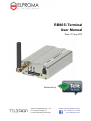
1
RB865i Terminal User Manual Date: 27 Aug 2013 Powered by Elproma Elektronika Sp. z o.o. ul. Szymanowskiego 13 05-092 Łomianki k/Warszawy 1 E-mail: [email protected] Tel. +48 (22) 751 76 80 www.teleorigin.com Contents 1. Overview................................................................................................................................... 4 2. References ................................................................................................................................. 4 3. Trademarks ............................................................................................................................... 5 4. Package ..................................................................................................................................... 6 4.1. Box ..................................................................................................................................... 6 5. Complete package contents ....................................................................................................... 7 6. General presentation .................................................................................................................. 8 6.1. Description ......................................................................................................................... 8 6.2. External connections ........................................................................................................... 9 6.2.1. Antenna connector........................................................................................................... 9 6.2.2. RS-232 Interface (EIA574) ............................................................................................ 10 6.2.3. Power supply connector................................................................................................. 11 6.2.4. Audio Input/Output ....................................................................................................... 12 6.2.5. SIM card holder............................................................................................................. 12 6.3. Product sticker .................................................................................................................. 13 7. Basic features and services .................................................................................................. 14 8. Using the modem................................................................................................................. 15 8.1. Setting up the modem ....................................................................................................... 15 8.2. Mounting the modem ........................................................................................................ 17 8.2.1. On DIN bus ................................................................................................................... 17 8.2.2. On the wall .................................................................................................................... 17 8.3. Checking the communication with the modem .................................................................. 18 8.4. Status of the modem (LEDs) ............................................................................................. 19 8.5. Disabling and enabling echo function ................................................................................ 19 8.6. Verifying the strength of received signal ........................................................................... 20 8.7. PIN code status ................................................................................................................. 20 8.8. Network registration ......................................................................................................... 21 8.8.1. GSM network registration ............................................................................................. 21 8.8.2. GPRS network registration ............................................................................................ 22 8.8.3. AT commands summary ................................................................................................ 23 9. Troubleshooting................................................................................................................... 24 9.1. No connection/communication with the modem ................................................................ 24 9.2. Receiving ERROR message .............................................................................................. 24 9.3. Receiving NO CARRIER message .................................................................................... 25 10. Technical characteristics ................................................................................................... 26 Elproma Elektronika Sp. z o.o. ul. Szymanowskiego 13 05-092 Łomianki k/Warszawy 2 E-mail: [email protected] Tel. +48 (22) 751 76 80 www.teleorigin.com 10.1. Mechanical characteristic .............................................................................................. 26 10.2. Housing description (dimensioning diagram) ................................................................. 26 11. Electrical characteristic ..................................................................................................... 27 11.1. Power supply ................................................................................................................. 27 11.2. RF characteristics .......................................................................................................... 27 11.2.1. Frequency ranges ....................................................................................................... 27 11.2.2. RF performance ......................................................................................................... 27 11.3. External antenna ............................................................................................................ 28 11.4. Environmental characteristic ......................................................................................... 28 12. Python Script Interpreter ................................................................................................... 29 13. Safety recommendations ................................................................................................... 31 13.1. General Safety ............................................................................................................... 31 13.2. Care and Maintenance ................................................................................................... 32 13.3. Responsibility................................................................................................................ 32 14. Accessories ....................................................................................................................... 33 14.1. Accessories critical for using modem............................................................................. 33 14.2. Additional accessories ................................................................................................... 34 15. On-line support ................................................................................................................. 35 Elproma Elektronika Sp. z o.o. ul. Szymanowskiego 13 05-092 Łomianki k/Warszawy 3 E-mail: [email protected] Tel. +48 (22) 751 76 80 www.teleorigin.com 1. Overview The RB865i Terminal is the complete modem solution for wireless m2m applications. Based on the Telit GL865 module, it is available as DUAL or QUAD band version and offers high level GSM/GPRS features in compact aluminium housing with all the standardized interfaces. Together with its small size and wide supply voltage range, makes it easy to integrate into all kinds of machines. The RB865i Terminal enabling voice, data, SMS and fax communication is a universal solution for all low-volume M2M and mobile data applications including metering, traffic systems, transportation and logistics, security, vending machines, and facility management. Device can be controlled by standard AT commands or by customer's application inside (embedded Python Script Interpreter), thus making it the smallest, complete SMT platform for m2m solutions. This document contains full RB865i modem description and gives information about installation and using it. 2. References [1] Telit_AT_Commands_Reference_Guide.pdf [2] Telit_GL865-DUAL/QUAD_Hardware_User_Guide.pdf [3] Telit_Modules_Software_User_Guide.pdf [4] Telit_GL865-DUAL/QUAD_Product_Description.pdf [5] Telit_Easy_Script_Python.pdf [6] http://www.telit.com/en/products/gsm-gprs.php?p_id=12&p_ac=show&p=93 [7] http://www.python.org/ Elproma Elektronika Sp. z o.o. ul. Szymanowskiego 13 05-092 Łomianki k/Warszawy 4 E-mail: [email protected] Tel. +48 (22) 751 76 80 www.teleorigin.com 3. Trademarks TELIT and the Stylized T Logo are registered in Trademark Office. All other product or service names are the property of their respective owners. Copyright © Telit Communications S.p.A. 2011. Elproma Elektronika Sp. z o.o. ul. Szymanowskiego 13 05-092 Łomianki k/Warszawy 5 E-mail: [email protected] Tel. +48 (22) 751 76 80 www.teleorigin.com 4. Package 4.1. Box Original box of the product is shown in the picture below. We can find product sticker on the box. It matches modems sticker that is placed on the device. This proves that your modem is original product. More information about stickers in chapter 6.3Product sticker. Elproma Elektronika Sp. z o.o. ul. Szymanowskiego 13 05-092 Łomianki k/Warszawy 6 E-mail: [email protected] Tel. +48 (22) 751 76 80 www.teleorigin.com 5. Complete package contents Complete package contains: RB865i terminal (item A) Power adaptor (item B) Elproma Elektronika Sp. z o.o. ul. Szymanowskiego 13 05-092 Łomianki k/Warszawy 7 E-mail: [email protected] Tel. +48 (22) 751 76 80 www.teleorigin.com 6. General presentation 6.1. Description SMA connector LEDs Power supply DATA GSM PWR Extractable SIM card holder SIM card holder ejector EIA574 (RS-232) DE9 D-sub socket Audio Input/Output Elproma Elektronika Sp. z o.o. ul. Szymanowskiego 13 05-092 Łomianki k/Warszawy 8 E-mail: [email protected] Tel. +48 (22) 751 76 80 www.teleorigin.com 6.2. External connections 6.2.1. Antenna connector SMA connector for antenna SMA antenna input is used to connect external GSM antenna. To establish connection with GSM network an external antenna must be used. Type of antenna depends on GSM coverage. In good circumstances (level of received signal is high) use antenna which is attached in the package. If range of GSM is low or none, an outdoor or indoor (for instance in place where GSM range is sufficient) antenna should be used. Note: If there is no antenna connected to SMA connector, the connection with GSM network is impossible. Elproma Elektronika Sp. z o.o. ul. Szymanowskiego 13 05-092 Łomianki k/Warszawy 9 E-mail: [email protected] Tel. +48 (22) 751 76 80 www.teleorigin.com 6.2.2. RS-232 Interface (EIA574) RB865i terminal is equipped with RS-232 interface (as shown below). DE9 DSUB socket is connected via voltage level translator circuit to GL865. EIA574 (RS-232) DE9 D-sub socket Female connector Table of RS-232 DB9 pins: Pin No. Name Dir Description 1 DCD IN Data Carrier Detect. Raised by DCE when modem synchronized. 2 RD IN Receive Data (a.k.a RxD, Rx). Arriving data from DCE. 3 TD OUT Transmit Data (a.k.a TxD, Tx). Sending data from DTE. 4 DTR OUT Data Terminal Ready. Raised by DTE when powered on. In auto-answer mode raised only when RI arrives from DCE. 5 SGND - Ground 6 DSR IN Data Set Ready. Raised by DCE to indicate ready. 7 RTS OUT Request To Send. Raised by DTE when it wishes to send. Expects CTS from DCE. 8 CTS IN Clear To Send. Raised by DCE in response to RTS from DTE. 9 RI IN Ring Indicator. Set when incoming ring detected - used for auto-answer application. DTE raised DTR to answer. DE-9 (EIA/TIA 574) looking into female connector Elproma Elektronika Sp. z o.o. ul. Szymanowskiego 13 05-092 Łomianki k/Warszawy 10 E-mail: [email protected] Tel. +48 (22) 751 76 80 www.teleorigin.com 6.2.3. Power supply connector The power supply connector is a 2-pin connector for external DC power supply connection, which can handle voltage from range 5..30 V DC, 2.5 W max. continuous power. Power supply connector No. Singal I/O Description + V+BATTERY I 5 V – 30 V DC - GND - Ground Attention! An attempt to power terminal from DC source outside of 5..30 V range may result in physical destruction of the device. Elproma Elektronika Sp. z o.o. ul. Szymanowskiego 13 05-092 Łomianki k/Warszawy 11 E-mail: [email protected] Tel. +48 (22) 751 76 80 www.teleorigin.com 6.2.4. Audio Input/Output The RB865i modem is equipped with audio interface, which can be used for transmitting voice communication while calling. To use this interface plug the HandsFree headphones into it. The Audio I/O is shown in the picture below. Audio Input/Output Interface 6.2.5. SIM card holder SIM card holder is placed in front of RB865i terminal (as shown below) and is accessible externally. To insert SIM card into the holder press the yellow button, eject the little drawer, place there Your SIM card and insert drawer into the modem (You will hear click). To operate the module in a GSM network, it is necessary to insert a SIM card obtained from the network operator. SIM card holder ejector Extractable SIM card holder Elproma Elektronika Sp. z o.o. ul. Szymanowskiego 13 05-092 Łomianki k/Warszawy 12 E-mail: [email protected] Tel. +48 (22) 751 76 80 www.teleorigin.com 6.3. Product sticker Product stickers are on the modem and on the box of the product. A production sticker includes the following information: Product serial number (IMEI) the CE marking the 15-digit bar code the model signature (RB865i) Elproma Elektronika Sp. z o.o. ul. Szymanowskiego 13 05-092 Łomianki k/Warszawy 13 E-mail: [email protected] Tel. +48 (22) 751 76 80 www.teleorigin.com 7. Basic features and services Basic features and available services for RB865i are contained in table below. Feature/service Standard GPRS Interfaces Description Supported Bands: GSM Quad-band 850/900/1800/1900MHz Physical: 83 x 72 x 25 mm Weight 151g Multi-slot class 10 (4 Down; 2 Up; 5 Total) Max BR Downlink 85.6 Kbps Coding Scheme CS1-CS4 Connectors Single 70 pin board to board RF MMCX SIM Card 3.0V / 1.8V STK 3.1 Connectivity USB 1.1 full speed UART: BR from 300 bps to 115.2 Kbps Auto BR SMS MO / MT Text and PDU mode Cell broadcast Audio Telephony Digital audio Differential analog audio lines Vocoders HR/FR/EFR/AMR DTMF support Audio control: echo suppression; noise suppression; side tone; gain control GSM supplementary services Power supply CSD USSD phase II Call forwarding Call hold; waiting; multiparty Call diverting Missed call indicator AOC Call barring Max BR 14.4 Kbps 5V – 30V DC Elproma Elektronika Sp. z o.o. ul. Szymanowskiego 13 05-092 Łomianki k/Warszawy 14 E-mail: [email protected] Tel. +48 (22) 751 76 80 www.teleorigin.com 8. Using the modem 8.1. Setting up the modem To set up the modem, do the following steps: Eject SIM card holder using yellow button and pull out the drawer. Eject SIM holder using yellow button and pull out drawer Insert Your SIM card into drawer. Put Your SIM card into drawer and insert the drawer into modem SIM car drawer can be completely taken out Verify if SIM card fits in the drawer properly (as shown). Insert the drawer into the modem. Elproma Elektronika Sp. z o.o. ul. Szymanowskiego 13 05-092 Łomianki k/Warszawy 15 E-mail: [email protected] Tel. +48 (22) 751 76 80 www.teleorigin.com Connect the antenna to the SMA connector Optionally it can be connected using RS-232 cable Plug the power supply cable to the power supply input Plug the hands-free headphones into Audio I/O Now the modem is ready to work. Elproma Elektronika Sp. z o.o. ul. Szymanowskiego 13 05-092 Łomianki k/Warszawy 16 E-mail: [email protected] Tel. +48 (22) 751 76 80 www.teleorigin.com 8.2. Mounting the modem 8.2.1. On DIN bus To mount modem on DIN bus install DIN handle as shown below 8.2.2. On the wall To mount modem on the wall install wall handles as shown below. Elproma Elektronika Sp. z o.o. ul. Szymanowskiego 13 05-092 Łomianki k/Warszawy 17 E-mail: [email protected] Tel. +48 (22) 751 76 80 www.teleorigin.com 8.3. Checking the communication with the modem Once the modem is connected You can check communication between RB865i terminal and the PC using Telit AT Controller available here: http://teleorigin.com/download/Tools/Common/Telit_AT_Controller_r2_2_1.zip Configuration of the DTE (port COM) should be as follows: Bits per second: 115200 bps, Data bits: 8, Parity: None, Stop bits: 1, Flow control: hardware. To communicate with modem use software such as Hyperterminal (AT commands) or use attached GPRS Control v.2.1.0.0 software. For further information about GPRS Control, refer to 'GPRS Control 3.1.0.0 User's Manual' [3], and to install refer to 'GPRS Control Installation Guide' [4]. Using a communication software such as Hyperterminal, enter the AT and push 'enter' button. The response of the terminal should be 'OK' displayed in the Hyperterminal window. If the connection with the modem cannot be established do the following: Check if modem is connected with PC via RS-232 or USB. Check the configuration of the COM port. Examples of AT commands: ATE1 enables modem echo function, AT+CGMI modem answers “Motorola” when connection is OK. AT+CPIN? shows current status of SIM card AT+CPIN=xxxx to enter PIN, where 'xxxx' are digitals AT+CSQ to verify received signal strength ATD<phone_number>; to initiate a voice call ATH to hang up a voice call For further information about AT commands and their usage, refer to [1]. Elproma Elektronika Sp. z o.o. ul. Szymanowskiego 13 05-092 Łomianki k/Warszawy 18 E-mail: [email protected] Tel. +48 (22) 751 76 80 www.teleorigin.com 8.4. Status of the modem (LEDs) The operational status of the RB865i Terminal is signalized by external LEDs placed on the front panel of the modem. The table below shows what is the meaning of LEDs. LED LED status name on off 8.5. LED colour Status description GPRS blue Lights when GPRS connection is established GSM orange Shows the RF activity of GSM module PWR green Modem is on GPRS none No GPRS connection is established GSM none Terminal has no connection with GSM network PWR none Modem is off Disabling and enabling echo function If echo is not displayed when entering AT command, that means: The local echo function in software (such as Hyperterminal) is disabled The echo function of the modem is disabled To enable echo function of the modem enter ATE1 command. In Machine to Machine communication it is recommended to disable echo function (type ATE0) in order to avoid useless CPU processing. For further information about AT commands and their usage, refer to [1]. Elproma Elektronika Sp. z o.o. ul. Szymanowskiego 13 05-092 Łomianki k/Warszawy 19 E-mail: [email protected] Tel. +48 (22) 751 76 80 www.teleorigin.com 8.6. Verifying the strength of received signal RB865i Terminal can establish connection with network if the received signal strength is sufficiently strong. To verify the signal strength and bit error rate, do the following: Using software such as Hyperterminal enter AT+CSQ. This command displays the received signal strength indication <rssi> and channel bit error rate <ber>. The modem answers as follows: +CSQ: <rssi>,<ber> OK <parameter> Description <rssi> 0 through 31 - covers the range of -113 dbm (or less) to -51dbm (or greater) <ber> Channel bit error rate (in percent) 0–7 RXQUAL values in the GSM 05.08 table 99 Unknown or not detectable For further information about AT commands and their usage, refer to [1]. 8.7. PIN code status To check PIN code status enter AT+CPIN? Command. The table below shows the most interesting responses of the modem: Answer Description +CPIN: SIM PIN PIN code has not been entered +CPIN: READY PIN code has been entered correctly For further information about AT commands and their usage, refer to [1]. Elproma Elektronika Sp. z o.o. ul. Szymanowskiego 13 05-092 Łomianki k/Warszawy 20 E-mail: [email protected] Tel. +48 (22) 751 76 80 www.teleorigin.com 8.8. Network registration 8.8.1. GSM network registration To check GSM network registration status enter AT+CREG? into software (for instance Hyperterminal) Modem will answer in following format: +CREG: <n>,<stat>[,<lac>,<ci>] OK The following table shows the +CREG parameters: <parameter> <n> Description 0 Disables the network registration unsolicited result code. 1 Enables the network registration unsolicited result code +CREG: <stat>. 2 Enables the network registration and location information in unsolicited reports and Read command +CREG:<stat>[,<lac>,<ci>]. The default is 0. <stat> 0 Not registered, and the ME is not currently searching for a new operator to which to register. 1 Registered, home network. 2 Not registered, but the ME is currently searching for a new operator to which to register. 3 Registration denied.* 4 Unknown. 5 Registered, roaming. <lac> Two-byte location area code in hexadecimal format <ci> Two-byte cell ID in hexadecimal format. *To manage connecting to network SIM card inserted into the modem must be valid. For further information about AT commands and their usage, refer to [1]. Elproma Elektronika Sp. z o.o. ul. Szymanowskiego 13 05-092 Łomianki k/Warszawy 21 E-mail: [email protected] Tel. +48 (22) 751 76 80 www.teleorigin.com 8.8.2. GPRS network registration To check GPRS network registration status enter AT+CGREG? into software (for instance Hyperterminal) Modem will answer in following format: +CGREG: <n>,<stat>[,<lac>,<ci>] OK The following table shows the +CGREG parameters: <parameter> <n> Description 0 Disables the network registration unsolicited result code. 1 Enables the network registration unsolicited result code +CGREG: <stat>. 2 Enables the network registration and location information in unsolicited reports and Read command +CGREG:<stat>[,<lac>,<ci>]. The default is 0. <stat> 0 Not registered, and the ME is not currently searching for a new operator to which to register. 1 Registered, home network. 2 Not registered, but the ME is currently searching for a new operator to which to register. 3 Registration denied.* 4 Unknown. 5 Registered, roaming. <lac> Two-byte location area code in hexadecimal format <ci> Two-byte cell ID in hexadecimal format. *To manage connecting to network SIM card inserted into the modem must be valid. For further information about AT commands and their usage, refer to [1]. Elproma Elektronika Sp. z o.o. ul. Szymanowskiego 13 05-092 Łomianki k/Warszawy 22 E-mail: [email protected] Tel. +48 (22) 751 76 80 www.teleorigin.com 8.8.3. AT commands summary As a conclusion table below shows most common and useful AT commands. For more AT commands refer to [1]. Action Syntax Response Comments Echo enable ATE1 OK Typed text is seen. Echo disable ATE0 OK Typed text is not seen. Voice call ATD<phoneNo>; OK Call initiated. Remember of ';' NO CARRIER/BUSY/NO ANSWER Connection failure. +CME ERROR: <err> General error* OPERATION NOT ALLOWED Security reason (such as SIM card not inserted) UNKNOWN CALLING ERROR Unknown reason Hung up call ATH NO CARRIER Connection is hanged up. Receiving call ATA OK Call is answered. NO CARRIER Communication loss Enter PIN code AT+CPIN=[<puk> or <pin>], [<newpin>] Check PIN code AT+CPIN? status OK Set PIN or PUK or new PIN code.* +CME ERROR: <err> General error* +CPIN: <code> OK Returns status of PIN. e.g. READY or SIM PIN +CME ERROR: <err> General error* *Refer to [1]. Elproma Elektronika Sp. z o.o. ul. Szymanowskiego 13 05-092 Łomianki k/Warszawy 23 E-mail: [email protected] Tel. +48 (22) 751 76 80 www.teleorigin.com 9. Troubleshooting 9.1. No connection/communication with the modem If there is no communication with the modem do the following steps: Check all external connections of the modem (RS-232 or USB, Power supply) Verify if power supply is correct (see 11.1 Power supply) Check if COM port is correctly parametrized (see 8.3 Checking the communication with the modem) Check if program used for communication works properly and if there is none other program interfering. If yes close the interfering program. 9.2. Receiving ERROR message Modem answers ERROR on AT command in following cases: Syntax of typed AT command is incorrect – check the command syntax in [1] Parameters of typed AT command are incorrect – type AT+CMEE=1 for enabling wide description of error which occurred. The response now will be in format: ERROR +CME ERROR: <err> where <err> is a description of error which has occurred Refer to [1] for further details about occurred error Elproma Elektronika Sp. z o.o. ul. Szymanowskiego 13 05-092 Łomianki k/Warszawy 24 E-mail: [email protected] Tel. +48 (22) 751 76 80 www.teleorigin.com 9.3. Receiving NO CARRIER message There are some common cases when modem answers NO CARRIER: If data/voice/fax connection cannot be established Right after hanging up the data/voice/fax connection If there is no connection with network – check antenna and registration status (see 8.8 Network registration) If there is no power supply (see 11.1 Power supply) If modem answers NO CARRIER in some cases, you can have extended error code using AT+CEER. The table below shows some of codes which can appear. Error code Description 1 Unassigned or unallocated number 3 No route to destination 6 Channel unacceptable 8 Operator determined barring 16 Normal call clearing 17 User busy 18 No user responding 19 User alerting, no answer 21 Call rejected 22 Number changed 27 Destination out of order 28 Invalid number format (incomplete number) 34 No circuit/channel available 38 Network out of order 41 Temporary failure For further information about AT commands and their usage, refer to [1]. Elproma Elektronika Sp. z o.o. ul. Szymanowskiego 13 05-092 Łomianki k/Warszawy 25 E-mail: [email protected] Tel. +48 (22) 751 76 80 www.teleorigin.com 10. Technical characteristics 10.1. Mechanical characteristic Max. dimensions 72 x 53.5 x 26 mm (w/o connectors) 83 x 53.5 x 26 mm (w/ connectors) Weight ≈ 89 g Volume 100 cm3 (w/o connectors) 10.2. Housing description (dimensioning diagram) Elproma Elektronika Sp. z o.o. ul. Szymanowskiego 13 05-092 Łomianki k/Warszawy 26 E-mail: [email protected] Tel. +48 (22) 751 76 80 www.teleorigin.com 11. Electrical characteristic 11.1. Power supply Nominal voltage range: 5..30 V, 10% Maximum continuous (average) supply power: 2.5 W Maximum continuous (average) supply current: 200 mA at 12V, 100 mA at 24V 11.2. RF characteristics 11.2.1. Frequency ranges Parameter Conditions Specifications GSM 850 TX 824 – 849 MHz RX 869 – 894 MHz TX 880 – 915 MHz RX 925 – 960 MHz TX 1710 – 1785 MHz RX 1805 – 1880 MHz TX 1850 – 1910 MHz RX 1930 – 1990 MHz GSM 900 DCS 1800 PCS 1900 11.2.2. RF performance Minimum radiated RF performance is shown in the table below: Band GSM/GPRS EGPRS 850/900 1800/1900 TRP [dBm] 22 24,5 TIS [dBm] -99 -101,5 TRP [dBm] 20,5 19,5 TIS [dBm] -92,5 -93,5 Elproma Elektronika Sp. z o.o. ul. Szymanowskiego 13 05-092 Łomianki k/Warszawy 27 E-mail: [email protected] Tel. +48 (22) 751 76 80 www.teleorigin.com 11.3. External antenna The external antenna is connected to the modem via SMA connector. Antenna must have parameters as shown below in table. Antenna frequency range Dual-band GSM 900/DCS 1800 MHz Impedance 50 Ω DC impedance 0Ω Gain 0 dBi w/o cable; 2dBi w/ cable VSWR (with cable) -10 dB The antenna chosen for working with modem should best fit to circumstances of environment it is used in. When the modem is placed in a room or somewhere where the range of networks signal is too low, the outdoor or specific indoor antenna should be used to increase it. 11.4. Environmental characteristic Table below gives the environmental operating conditions of RB865i terminal. Attention! Exceeding the values may result in permanent damage to the module. Parameter Conditions Min Max Unit Ambient Operating Temperature -20 60 °C Storage Temperature -40 85 °C ESD At antenna connector Contact Air At interface connector Elproma Elektronika Sp. z o.o. ul. Szymanowskiego 13 05-092 Łomianki k/Warszawy 28 KV ±6 ± 15 ±1 E-mail: [email protected] Tel. +48 (22) 751 76 80 www.teleorigin.com 12. Python Script Interpreter The Easy Script Extension is a feature that allows driving the modem internally, writing the controlling application directly in the Python high level language. A typical application usually consists of a microcontroller managing several I/O pins on the module through the AT command interface. The Easy Script Extension functionality lets the developer to get rid of the external controller and further simplify the programmed sequence of operations. The equipped Python version features the following: Python script interpreter engine v.1.5.2+ 1 MB (2 MB in versions up to 10.0x.xx5) of Non Volatile Memory space for user scripts and data 1.2 MB RAM reserved for the Python engine The following depicts a schematic of this approach: To use Python language features on Telit module use PythonWin. It is an Python editor for Windows. In order for the software to function correctly, it is required the use of either Windows 2000 or XP as operating systems. PythonWin can be found here http://www.python.org/download/windows/ Python scripts are text files stored in Telit module NVM (Non Volatile Memory). There is a file system inside the module that allows to write and read files with different names on one single level (no subdirectories are supported) Elproma Elektronika Sp. z o.o. ul. Szymanowskiego 13 05-092 Łomianki k/Warszawy 29 E-mail: [email protected] Tel. +48 (22) 751 76 80 www.teleorigin.com The Python script is executed in a task with the lowest priority on the Telit module, so it’s execution won’t interfere with GSM/GPRS normal operations. Furthermore, this allows serial ports, protocol stack etc. to run independently from the Python script. The Python script interacts with the Telit module functionalities through several built-in interfaces, as depicted below: The MDM interface is the most important one. It allows the Python script to send AT commands, receive responses and unsolicited indications, send data to the network and receive data from network during connections. It is quite similar to the regular serial port interface on the Telit module. The only difference being that this interface is an internal software bridge between Python and module internal AT command handling engine, and not a physical serial port. All AT commands working on the Telit module are working with this software interface as well. The MDM2 interface is the second interface between Python and the module internal AT command handling. It’s purpose is to send AT commands from the Python script to the module and receive AT responses from the module to the Python script when the regular MDM built-in module is already in use. The SER interface lets the Python script to read from and write to the physical serial port ASC0, usually the default port to send AT commands to the module (e.g. to read information from an external device). When Python is running, this serial port is free to be use by the Python script since it is not used as the AT command interface; the AT parser, in fact, is mapped into the internal virtual serial port. No flow control is available from Python on this port. The SER2 interface lets Python script to read from and write to the physical serial port ASC1, usually the default port for tracing and debugging. The GPIO interface lets the Python script to handle general purpose input output faster than through AT commands, skipping the command parser and controlling directly the pins. The MOD interface is a collection of useful functions The II2 interface is an implementation on the Python core of the IIC bus Master. It allows Python to create one or more IIC bus on the available GPIO pins. The SPI interface is an implementation on the Python core of the SPI bus Master. It allows Python to create one or more SPI bus on the available GPIO pins. The GPS interface is the interface between Python and the module’s internal GPS controller. Its purpose is to handle the GPS controller without the use of dedicated AT commands through the MDM built-in module. Visit Python official web site for more information http://www.python.org/. More information can be found also in Telit_Easy_Script_Python.pdf [5] Elproma Elektronika Sp. z o.o. ul. Szymanowskiego 13 05-092 Łomianki k/Warszawy 30 E-mail: [email protected] Tel. +48 (22) 751 76 80 www.teleorigin.com 13. Safety recommendations 13.1. General Safety Please follow safety regulations regarding the use of radio equipment due to the possibility of radio frequency interference. Read given advices carefully. Switch off GSM terminal when: in an aircraft – using cellular telephones in aircraft may endanger the operation of the aircraft; it is illegal at a refuelling point in any area with potentially explosive atmosphere which could cause an explosion or fire in hospitals and any other places where medical equipment is in use Respect restrictions on the use of radio equipment in any area or place where it is signalized that using cellular telephony is forbidden or dangerous. Using GSM modem close to other electronic equipment may also cause interference if the equipment is inadequately protected. It may lead to damage or failure of GSM modem or the other equipment. Elproma Elektronika Sp. z o.o. ul. Szymanowskiego 13 05-092 Łomianki k/Warszawy 31 E-mail: [email protected] Tel. +48 (22) 751 76 80 www.teleorigin.com 13.2. Care and Maintenance The RB865i terminal is a electronic product that should be treated with care. Please follow suggestions shown below due to using modem for many years. Do not expose RB865i to any extreme circumstances like high temperature or high humidity Do not keep modem in dirty and dust places Do not disassemble the RB865i modem Do not expose the modem to any water, rain or steam Do not drop, shake or knocking your modem Do not place your modem close to magnetic devices – credit cards, etc Use of third party equipment or accessories, not made or authorized by Elproma Electronics may invalid the warranty of modem and/or cause failure or permanent damage of modem Do not expose the modem to children under 3 years 13.3. Responsibility The modem is under your responsibility. Please treat it with care, and respect local regulations. This is not a toy – keep it out of the reach of children. Try to use security features (PIN etc.) to block unauthorized use or theft. Elproma Elektronika Sp. z o.o. ul. Szymanowskiego 13 05-092 Łomianki k/Warszawy 32 E-mail: [email protected] Tel. +48 (22) 751 76 80 www.teleorigin.com 14. Accessories The tables below shows recommended accessories for RB865i terminal. 14.1. Accessories critical for using modem Table below shows accessories critical for using modem. Without them usage of modem is impossible. Accessory Description Power adaptor Part no. 5V Example of power adaptor is shown in the picture below Power adaptor 5 V Elproma Elektronika Sp. z o.o. ul. Szymanowskiego 13 05-092 Łomianki k/Warszawy 33 E-mail: [email protected] Tel. +48 (22) 751 76 80 www.teleorigin.com 14.2. Additional accessories Table below shows additional accessories that are not essential for modem usage. Accessory Description Part no. Magnetic antenna 2dBi Antenna with extra gain ANT-DBMAG HandsFree headphones Headphones and microphone HF24 Magnetic antenna 2dBi ANT-DBMAG HandFree headphones HF24 Elproma Elektronika Sp. z o.o. ul. Szymanowskiego 13 05-092 Łomianki k/Warszawy 34 E-mail: [email protected] Tel. +48 (22) 751 76 80 www.teleorigin.com 15. On-line support Elproma provides a range on on-line support which includes: the latest version of this document the latest drivers for RB865i technical support This information can be found on our web sites at www.teleorigin.com For further information You can contact us at: email: [email protected] forum: www.elproma.fora.pl tel.: +48 (22) 751 76 80 fax.: +48 (22) 751 76 81 skype: elproma.elektronika Elproma Elektronika Sp. z o.o. ul. Szymanowskiego 13 05-092 Łomianki k/Warszawy 35 E-mail: [email protected] Tel. +48 (22) 751 76 80 www.teleorigin.com