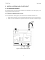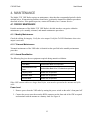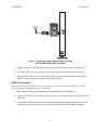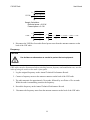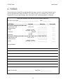
1
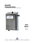
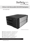
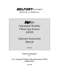
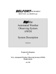
Model 1792 VHF Radio × FAA APPROVED ECP202 — 2014 Dec 30 NOT FAA APPROVED User’s Manual Rev. B All Weather Inc. • 1165 National Drive • Sacramento, CA 95834 • USA • 800.824.5873 • www.allweatherinc.com Copyright © 2011, All Weather, Inc. All Rights Reserved. The information contained herein is proprietary and is provided solely for the purpose of allowing customers to operate and/or service All Weather, Inc. manufactured equipment and is not to be released, reproduced, or used for any other purpose without written permission of All Weather, Inc. Throughout this manual, trademarked names might be used. Rather than put a trademark (™) symbol in every occurrence of a trademarked name, we state herein that we are using the names only in an editorial fashion and to the benefit of the trademark owner, and with no intention of infringement. All Weather, Inc. and the All Weather, Inc. logo are trademarks of All Weather, Inc. Disclaimer The information and specifications described in this manual are subject to change without notice. Latest Manual Version For the latest version of this manual, see the User Manuals page on our web site at http://www.allweatherinc.com/support/support-library/user-manuals/. All Weather, Inc. 1165 National Drive Sacramento, CA 95834 Tel.: (916) 928-1000 Fax: (916) 928-1165 Contact Customer Service Phone support is available from 8:00am - 4:30pm PT, Monday through Friday. Call 916-928-1000 and ask for “Service.” Online support is available by filling out a request at www.allweatherinc.com/support/online-support/ E-mail your support request to [email protected] 1792 VHF Radio User's Manual TABLE OF CONTENTS 1. OVERVIEW .........................................................................................................................1 2. INSTALLATION AND CHECKOUT .....................................................................................2 2.1 Set Operating Frequency ............................................................................................................ 2 2.1.1 Remove the Bottom Enclosure Cover................................................................................. 2 2.1.2 Set the Transmitter Frequency ............................................................................................ 3 2.1.3 Replace the Bottom Enclosure Cover ................................................................................. 7 2.2 Mounting Bracket ....................................................................................................................... 7 2.3 Calibration .................................................................................................................................. 8 2.4 Connections ................................................................................................................................ 8 2.5 Operational Check ...................................................................................................................... 9 3. OPERATING INSTRUCTIONS ......................................................................................... 10 3.1 Switches, Controls, and Indicators ........................................................................................... 10 3.2 Operating Instructions .............................................................................................................. 11 3.2.1 Switching VHF Radio OFF .............................................................................................. 11 4. MAINTENANCE ................................................................................................................ 12 4.1 Periodic Maintenance ............................................................................................................... 12 4.1.1 Monthly Maintenance ....................................................................................................... 12 4.1.2 Triannual Maintenance ..................................................................................................... 12 4.1.3 Annual Revalidation ......................................................................................................... 12 4.2 Voice Output Static Reduction ................................................................................................. 17 4.3 Fuse Replacement ..................................................................................................................... 17 5. SPECIFICATIONS ............................................................................................................ 18 6. FORMS ............................................................................................................................. 19 7. WARRANTY ...................................................................................................................... 20 1792 VHF Radio User's Manual 1. OVERVIEW The Model 1792 VHF Radio is a single-channel, fixed-frequency, low-power transmitter intended for base station operation in an air traffic environment to broadcast audio automated weather observations from the AWOS 3000. The Model 1792 VHF Radio operates over the frequency range from 117.975 MHz to 138.000 MHz, and uses DC power (negative ground only). The frequency is programmable over the specified frequency range with a channel spacing of 25 kHz. The Model 1792 VHF Radio includes the following items. Mounting Bracket — A U-shaped aluminum alloy bracket is used to mount the Model 1792 VHF Radio in the AWOS 3000 CDP rack. Power Input Cable Assembly — A 12" (30 cm) two- core cable terminated at one end by a two-pin (female contacts) connector mates with the two-pin (male contacts) power connector at the back of the Model 1792 VHF Radio. The cable provides DC power from the AWOS CDP rack. VHF Radio Signal Cable Assembly — A 36" (90 cm) cable terminated at one end with a male DB9 connector delivers the VHF voice output and the keying instructions that turn the transmitter on/off. This cable connects to a female DB9 connector on the side of the Model 1792 VHF Radio. An RG-58 antenna cable in the AWOS 3000 CDP rack connects the antenna output on the back of the Model 1792 VHF Radio to the antenna connector on the back of the CDP rack. 1 1792 VHF Radio User's Manual 2. INSTALLATION AND CHECKOUT 2.1 SET OPERATING FREQUENCY The operating frequency must be set before the Model 1792 VHF Radio is used. The frequency is set using jumpers inside the radio enclosure. 2.1.1 Remove the Bottom Enclosure Cover To access the frequency setting jumpers, you must first remove the bottom enclosure cover. 1. Remove and set aside the 13 screws securing the bottom enclosure cover to the radio chassis. 2. Lift the cover clear of the chassis to expose the internal view of the radio as shown in Figure 1. Figure 1. Model 1792 Internal View 2 1792 VHF Radio User's Manual 2.1.2 Set the Transmitter Frequency The operating frequency may be programmed over the frequency range from 117.975 MHz to 138.000 MHz with a 25 kHz channel spacing. 1. Determine the operating frequency to be programmed. Jumpers on the Single-Channel Memory Set Board (Figure 2) are used to set the frequency based on its MHz and kHz components. Figure 2. Frequency Set Jumpers 3 1792 VHF Radio User's Manual 2. Refer to Table 1 to select the integer portion of the frequency. Find the desired frequency in the Operating Frequency column, and install the jumper(s) accordingly. Table 1. MHz Frequency Selection Jumper Settings Operating Frequency (MHz) 117 20 MHz 10 MHz 8 MHz 4 MHz 2 MHz 1 MHz 0 1 0 1 1 1 118 1 1 1 0 0 0 119 0 1 1 0 0 1 120 1 0 0 0 0 0 121 1 0 0 0 0 1 122 1 0 0 0 1 0 123 1 0 0 0 1 1 124 1 0 0 1 0 0 125 1 0 0 1 0 1 126 1 0 0 1 1 0 127 1 0 0 1 1 1 128 1 0 1 0 0 0 129 1 0 1 0 0 1 130 1 1 0 0 0 0 131 1 1 0 0 0 1 132 1 1 0 0 1 0 133 1 1 0 0 0 1 134 1 1 0 1 0 0 135 1 1 0 1 0 1 136 1 1 0 1 1 0 137 1 1 0 1 1 1 138 1 1 1 0 0 0 Jumper Location 4 1792 VHF Radio User's Manual 3. Refer to Table 2 to select the decimal portion of the frequency. Since 0.001 MHz is 1 kHz, this portion of the frequency is expressed in kHz in the table. Find the desired frequency in the Operating Frequency column, and install the jumper(s) accordingly. Table 2. kHz Frequency Selection Jumper Settings Operating Frequency (kHz) 000 800 kHz 400 kHz 200 kHz 100 kHz 50 kHz 25 kHz 0 0 0 0 0 0 025 0 0 0 0 0 1 050 0 0 0 0 1 0 075 0 0 0 0 1 1 100 0 0 0 1 0 0 125 0 0 0 1 0 1 150 0 0 0 1 1 0 175 0 0 0 1 1 1 200 0 0 1 0 0 0 225 0 0 1 0 0 1 250 0 0 1 0 1 0 275 0 0 1 0 1 1 300 0 0 1 1 0 0 325 0 0 1 1 0 1 350 0 0 1 1 1 0 375 0 0 1 1 1 1 400 0 1 0 0 0 0 425 0 1 0 0 0 1 450 0 1 0 0 1 0 475 0 1 0 0 1 1 500 0 1 0 1 0 0 525 0 1 0 1 0 1 550 0 1 0 1 1 0 575 0 1 0 1 1 1 600 0 1 1 0 0 0 625 0 1 1 0 0 1 650 0 1 1 0 1 0 675 0 1 1 0 1 1 700 0 1 1 1 0 0 725 0 1 1 1 0 1 750 0 1 1 1 1 0 775 0 1 1 1 1 1 800 1 0 0 0 0 0 Jumper Location 5 1792 VHF Radio User's Manual Operating Frequency (kHz) 825 800 kHz 400 kHz 200 kHz 100 kHz 50 kHz 25 kHz 1 0 1 1 0 1 850 1 0 0 0 1 0 875 1 0 0 0 1 1 900 1 0 0 1 0 0 925 1 0 0 0 0 1 950 1 0 0 0 1 0 975 1 0 0 0 1 1 Jumper Location Figure 3 shows an example of the jumper setting for a frequency of 123.175 MHz. Figure 3. Jumper Settings for 123.175 MHz 6 1792 VHF Radio User's Manual 2.1.3 Replace the Bottom Enclosure Cover 1. Position the bottom cover on the chassis. 2. Position one screw in each corner of the bottom cover mounting holes. 3. Secure the three screws for the “inside” of the enclosure cover. 4. Secure the remaining screws in the holes around the enclosure perimeter. 2.2 MOUNTING BRACKET The CDP rack’s bottom shelf (Figure 4) is fixed in place. Components are accessible through the rack’s front or side doors. The VHF radio is secured to the bottom side of the sliding top shelf using the mounting bracket, with the control knobs facing to the right when the VHF radio is viewed from the front end of the CDP rack. Figure 4. CDP Bottom-Shelf Components The mounting bracket and the VHF radio are installed at the factory. Should the need arise to remove the radio, undo the wing screws on either side of the radio. Because of the tight space inside the CDP rack, it is recommended that any connecting cables remain in place until the VHF radio is removed from the mounting bracket. Any cables that have been removed should be reattached before mounting the VHF radio back in the mounting bracket. There is no need to remove the mounting bracket itself. 7 1792 VHF Radio User's Manual Figure 5 shows the VHF radio secured in the mounting bracket. Figure 5. VHF Radio Secured in Mounting Bracket Using Wing Screws 2.3 CALIBRATION The Model 1792 VHF Radio is calibrated at the factory prior to shipment, and should not need to be calibrated again during installation. Power level and modulation calibration are performed as part of the annual revalidation described in Section 4.1.3. 2.4 CONNECTIONS The VHF radio is connected to existing connectors in the CDP rack as shown in Figure 6. Follow these steps. 1. Ensure that the VHF radio’s POWER ON/OFF switch is set to OFF. 2. Connect the M491852-00 antenna cable from the VHF RG58 connector on the back side of the CDP rear panel to the RG58 antenna connector at the back of the VHF radio. 3. Connect the M491844-00 signal cable’s DB9 connector to the DB9 connector on the side of the VHF radio. 4. Connect the M491850-00 power supply cable to the power supply connector on the rear side of the VHF radio. The red wire is positive, and the black wire is the negative supply ground 5. Power on the radio by switching the radio's POWER ON/OFF switch to ON. 8 1792 VHF Radio User's Manual Figure 6. VHF Radio Connections 2.5 OPERATIONAL CHECK Ensure that the VHF radio operates as described in the operating instructions in Chapter 3. Section 4.2 describes how to reduce the static if it is evident in the broadcast. 9 1792 VHF Radio User's Manual 3. OPERATING INSTRUCTIONS 3.1 SWITCHES, CONTROLS, AND INDICATORS Figure 7 shows the switches, controls, and indicators on the front panel of the VHF radio. Figure 7. VHF Radio Front Panel Controls Table 3 provides a functional description of each of the VHF radio switches, controls, and indicators. Table 3. Description of VHF Radio Switches, Controls, and Indicators SWITCHES CONTROLS & INDICATORS FUNCTIONAL DESCRIPTION POWER ON/OFF SWITCH A two-position toggle switch controls the application of the power supply to the VHF radio. Position 1, toggle UP, the VHF radio is switched ON. Position 0, toggle DOWN, the VHF radio is switched OFF. POWER ON LED INDICATOR A green LED is ON when the POWER ON/OFF switch is set to Position 1, and power is applied to the VHF radio. FUSE A 5 A fuse which protects the power supply line. As part of reverse polarity protection, the fuse will “blow” if the polarity of the supply line is reversed. FUSE BLOWN RED LED INDICATOR A red LED goes ON when the 5 A fuse is “blown” while power is applied to the VHF radio. 10 1792 VHF Radio User's Manual SWITCHES CONTROLS & INDICATORS SQUELCH CONTROL SQUELCH INDICATOR GREEN LED Tx ON YELLOW LED INDICATOR FUNCTIONAL DESCRIPTION The unlabeled squelch control above and to the right of the fuse is not used, and should remain in the fully counter clockwise position. The squelch indicator LED above the unlabeled squelch control should remain off since the squelch control is not used. A yellow LED is ON when the VHF radio is transmitting. The Tx ON yellow LED is OFF at other times. VOLUME CONTROL The volume control to the right of and below the Tx ON LED is not used, and should remain in the fully counter clockwise position. MIC/PTT CONNECTOR The MIC/PTT connector below the unlabeled volume control is not used. SPEAKER/ HEADPHONE CONNECTOR The speaker/headphone connector next to the MIC/PTT connector is not used. 3.2 OPERATING INSTRUCTIONS CAUTION Antenna must be connected to VHF radio before turning power on. 1. Ensure that the signal and antenna cables are connected. 2. Set the POWER ON/OFF switch to ON. 3. Verify that the POWER ON green LED is ON. 4. Verify that the AWOS station voice message is being transmitted. 5. Ensure that the Tx ON yellow LED cycles ON during voice message output. 6. Verify that the Tx ON yellow LED cycles OFF between voice message broadcasts. 3.2.1 Switching VHF Radio OFF 1. Set the POWER ON/OFF switch to OFF. 2. Verify that all indicator LEDs on the front panel are OFF. 11 1792 VHF Radio User's Manual 4. MAINTENANCE The Model 1792 VHF Radio requires no maintenance, other than the recommended periodic checks outlined below. If transmission problems should arise, perform the Annual Revalidation procedures described in below. If the problem persists, contact All Weather, Inc. Customer Service. 4.1 PERIODIC MAINTENANCE Periodic maintenance of the Model 1792 VHF Radio is divided into three categories within the maintenance cycle: monthly, triannual, and annual maintenance procedures. 4.1.1 Monthly Maintenance Check the cabling for integrity. Verify the voice output. Verify the Tx LED illuminates when voice output is activated. 4.1.2 Triannual Maintenance Triannual maintenance of the VHF radio is identical to that specified in the monthly maintenance procedure. 4.1.3 Annual Revalidation The following list gives the test equipment required during annual revalidation. Radio Test Equipment: Power Meter Bird Watt Meter Model 43 or equivalent Forward/Reflected Power Tester Bird Watt Meter Model 43 w/ 10C elements or equivalent Frequency Meter Aeroflex 3500 or equivalent Modulation Meter Aeroflex 3500 or equivalent Deviation Meter Aeroflex 3500 or equivalent When VHF antenna cables are longer than 50 feet, tests must be repeated at the antenna end of the cable. Power Level 1. Remove power from the VHF radio by turning the power switch on the radio’s front panel off. 2. Connect the power meter between the RG58 connector on the front end of the CDP rear panel and terminate with the antenna or a dummy load. See Figure 8. 12 1792 VHF Radio User's Manual Figure 8. Insert Power Meter Between Antenna Cable and CDP Back Panel VHF Connector 3. Apply power to the VHF radio by turning the power switch on the radio’s front panel on. 4. Record the VHF radio output power level on the Annual Technical Performance Record. 5. Turn the VHF radio power off, remove the power meter, and reconnect the antenna cable to the RG58 connector on the front end of the CDP rear panel. VSWR (at transmitter) If RF cables must be disconnected when switching between power level and VSWR tests, turn the radio off using the switch on the radio’s front panel. 1. Disconnect the M491852-00 antenna cable from the back of the VHF radio. 2. Connect a VSWR or forward/reflected power tester to the antenna connector on the back of the VHF radio. 3. Measure the VSWR and enter the value on the Annual Technical Performance Record. If you measure forward and reflected power, calculate the VSWR using the following equation. 13 1792 VHF Radio User's Manual reflectedpower forwardpower VSW R reflectedpower 1 forwardpower 1 Sample Calculation: Reflected power = 0.02 W Forward power = 2.5 W reflected _ power forward _ power 0.02 1 0.008 1 0.0894 1.0894 2.5 VSWR 1.1964 reflected _ power 0.02 1 0.008 1 0.0894 0.9106 1 1 forward _ power 2.5 1 1 4. Disconnect the VSWR or forward/reflected power tester from the antenna connector on the back of the VHF radio. Frequency CAUTION Use isolators or attenuators as needed to protect the test equipment. If RF cables must be disconnected when switching between frequency and modulation tests, turn the radio off using the switch on the radio’s front panel. 1. Log the assigned frequency on the Annual Technical Performance Record. 2. Connect a frequency meter to the antenna connector on the back of the VHF radio. 3. The radio transmits for approximately 30 seconds, followed by an off time of five seconds. While the radio is transmitting, measure the frequency. 4. Record the frequency on the Annual Technical Performance Record. 5. Disconnect the frequency meter from the antenna connector on the back of the VHF radio. 14 1792 VHF Radio User's Manual Modulation CAUTION Use isolators or attenuators as needed to protect the test equipment. If RF cables must be disconnected when switching between frequency and modulation tests, turn the radio off using the switch on the radio’s front panel. 1. Log in as an administrator on the CDP display and insert an AWOS Security Key CD. You will be able to access the menus once the optical drive light stops blinking, indicating that the AWOS Security Key CD has been read. 2. Connect a modulation meter to the antenna connector on the back of the VHF radio. Set the modulation meter to the instantaneous mode. 3. Access the Edit > Configuration > Voice tab on the CDP display and click the 300 Hz tone option in the Test panel. 15 1792 VHF Radio User's Manual 4. Use the modulation adjustment potentiometer on the VHF radio to adjust the modulation depth to 90%. Figure 9. VHF Radio Modulation Adjustment Potentiometer 5. Use the VHF adjustment potentiometer (R29) on the CDP peripheral interface board to lower the signal level until the modulation decreases to 80%. Figure 10. VHF Adjustment Potentiometer on CDP Peripheral Interface Board 6. Use the modulation adjustment potentiometer on the VHF radio to adjust the modulation depth to 60%. 7. Set the modulation meter to the “peak hold” mode. 16 1792 VHF Radio User's Manual 8. Access the Edit > Configuration > Voice tab on the CDP display and click the Modulated 300 Hz tone option in the Test panel. 9. Reset the modulation meter and wait until the modulated tone stops. 10. Verify that the peak modulation reading does not exceed 95%. If it does, adjust the modulation adjustment potentiometer on the VHF radio and recheck the peak modulation reading. 11. Access the Edit > Configuration > Voice tab on the CDP display and click the Word option in the Test panel. 12. Reset the modulation meter and wait until the words stop. Verify that the peak modulation reading does not exceed 95%. If it does, adjust the modulation adjustment potentiometer on the VHF radio and recheck the peak modulation reading. 13. Enter the final modulation meter reading on the Annual Technical Performance Record. 14. Turn the VHF radio off using the front panel switch. Disconnect the test equipment and cables, and reconnect the M491852-00 antenna cable. Turn the radio on. 15. Remove the CD Key from the CDP optical drive. 4.2 VOICE OUTPUT STATIC REDUCTION The Model 1792 VHF Radio has been adjusted for use with the AWOS 3000 to minimize audible static on the voice transmission. The following steps described how to reduce static should additional adjustment be required. 1. Adjust the VHF voice output signal at the CDP peripheral interface board by adjusting trim potentiometer R29 (see the Modulation section above) until the desired reduction in static is achieved. 2. Adjusting the VHF voice output signal will also change the modulation level. Increase the modulation level as described in the Modulation section above. 4.3 FUSE REPLACEMENT A 5 A fuse is located on the front panel of the Model 1792 VHF Radio. Check this fuse first if the VHF radio should fail, and replace as necessary with an appropriately rated replacement. 17 1792 VHF Radio User's Manual 5. SPECIFICATIONS Parameter Specification Frequency Range 117.975 to 138.000 MHz Channel Spacing 25 kHz Duty Cycle 20% Transmitter Power Output 5 to 10 W Output Power Stability 1.1 W VSWR 4:1 Carrier Stability (-40 to +55ºC) ±1.000 Hz max Incidental FM and PM from Modulation ±100 Hz max Rise Time to 90% Rated Power 100 ms max Audio Input 50 mV to 2 V rms Speech Processor Dynamic Range 35 dB min Modulation Capability up to 95% Audio Distortion (90% modulation) 10% max Audio Frequency Response 300 Hz to 2500 Hz (+1, -3 dB) Spurious Emissions 60 dB below carrier Hum and Noise Level 45 dB below carrier Voice/Keying Connector DB9 (female 9-pin D-sub connector) Antenna Connector RG58 Power Supply Connector 4-pin CPC Supply Voltage 11–15 V DC Transmit Mode — 5.0 A max Standby — 1.5 A max Current Consumption Operating Temperature -40 to +131ºF (-40 to +55ºC) Storage Temperature -67 to +149ºF (-55 to +65ºC) Humidity up to 100% noncondensing Enclosure powder-coated aluminum 8.50" W × 2.75" H × 10.25" D (216 mm × 70 mm × 260 mm) Dimensions Weight 3.5 lb (1.6 kg) Shipping Weight 5 lb (2.3 kg) 18 1792 VHF Radio User's Manual 6. FORMS These master forms should be copied and sufficient copies stored at a convenient location in each site's Facility Reference Data File (FRDF). The Annual Technical Performance Record is to be completed at system commissioning, after major repair work, and during annual revalidation. AWOS Annual Technical Performance Record Site Name and Location ___________________________________ VHF Radio Date _______________ Expected Measured Perform the following at the VHF radio Output Power Level 2.5 W, ±1 W ________________ Reflected Power ________________ Initial: 2.0:1 max. VSWR Operating: 3.0:1 max. ________________ Frequency assigned: ________________ ±1.0 kHz ________________ Modulation 65–95% ________________ Perform the following at the VHF antenna when cable runs are longer than 50 ft Output Power Level 1.0 W, ±0.5 W ________________ Reflected Power ________________ Initial: 2.0:1 max. VSWR Operating: 3.0:1 max. ________________ Pass (Y/N) Comments/Notes: System Checked By: ____________________________ 19 Date/Time: ___________________ _____ _____ _____ _____ _____ _____ _____ _____ 1792 VHF Radio User's Manual 7. WARRANTY Unless specified otherwise, All Weather Inc. (the Company) warrants its products to be free from defects in material and workmanship under normal use and service for one year from date of shipment, subject to the following conditions: (a) The obligation of the Company under this warranty is limited to repairing or replacing items or parts which have been returned to the Company and which upon examination are disclosed, to the Company’s satisfaction, to have been defective in material or workmanship at time of manufacture. (b) The claimant shall pay the cost of shipping any part or instrument to the Company. If the Company determines the part to be defective in material or workmanship, the Company shall prepay the cost of shipping the repaired instrument to the claimant. Under no circumstances will the Company reimburse claimant for cost incurred in removing and/or reinstalling replacement parts. (c) This warranty shall not apply to any Company products which have been subjected to misuse, negligence or accident. (d) This warranty and the Company’s obligation thereunder is in lieu of all other warranties, express or implied, including warranties of merchantability and fitness for a particular purpose, consequential damages and all other obligations or liabilities. No other person or organization is authorized to give any other warranty or to assume any additional obligation on the Company’s behalf, unless made in writing and signed by an authorized officer of the Company. 20 All Weather Inc. 1165 National Drive Sacramento, CA 95818 Fax: 916.928.1165 Phone: 916.928.1000 Toll Free: 800.824.5873 1792-001 Revision B August, 2011