1
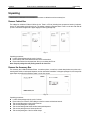
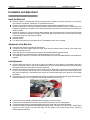
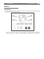
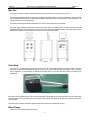
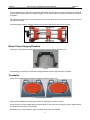
X-631/X-631+ Installation and Parts Manual
LAUNCH
Table of Contents
Precautions for Operation..........................................................................................................................................................1
Unpacking....................................................................................................................................................................................2
Remove Cabinet Box................................................................................................................................................................2
Remove the Accessory Box......................................................................................................................................................2
Installation and Adjustment.......................................................................................................................................................3
Install the Main Unit ..................................................................................................................................................................3
Adjustment of the Main Unit .....................................................................................................................................................3
Link Adjustment ........................................................................................................................................................................3
Structure......................................................................................................................................................................................4
Overall Structure.......................................................................................................................................................................4
Main Unit ..................................................................................................................................................................................5
Probe Rods...............................................................................................................................................................................5
Wheel Clamps ..........................................................................................................................................................................5
Wheel Clamp Hanging Brackets...............................................................................................................................................6
Turntables.................................................................................................................................................................................6
Steering Wheel Holder .............................................................................................................................................................7
Brake Pedal Depressor ............................................................................................................................................................7
Calibrating Frame and its Converter Connector (Optional) ......................................................................................................7
Part List........................................................................................................................................................................................8
ⅰ
LAUNCH
X-631/X-631+ Installation and Parts Manual
Precautions for Operation
Precautions for Operation
z
z
z
z
z
z
z
z
z
z
z
z
z
z
z
Please read the User’s Manual and the Installation and Parts Manual carefully before operating X-631or X-631+.
Only the qualified technician can operate the Wheel Aligner.
The operator must have knowledge of computer application and basic theory of wheel alignment.
The power voltage of X-631/X-631+ is AC220V±10% 50±1Hz / AC110V±10% 60±1Hz(It can be customized
according to the requirements of customer). The 3-terminal socket must be used, and the earth terminal must be
well grounded. If the power voltage is not stable, please purchase and use AC voltage stabilizer.
X-631/X-631+ is operated with image sensing. Do not stop the light beam between sensors. Avoid reflection light of
the ground and direct light to the probe rod while testing.
Charge the probe rod for 4 hours if it is not operated for over 30 days.
The probe rods are precision parts of the wheel aligner. Do not plug or unplug the connecting cable when the power
is turned on. Otherwise, the built-in sensor may be broken. Special care should be taken during installation and
operation to prevent the casing from being distorted and the internal parts from being damaged.
Install the lift according to specifications before installing X-631/X-631+, for it is necessary to lift the vehicle when
adjusting vehicle wheels. The vehicle may need lift for two times for compensation of rim run-out. Check the lift
regularly for fixedness and levelness to ensure personal safety and correct measurement. Remove the obstacles
around the lift for convenient operation.
Don’t place X-631/X-631+ on a vibrated object or an oblique surface. Avoid direct sunlight and moisture.
Avoid splashing water on the surface of X-631, for it may cause permanent damage when entering the system.
The wires inside the cabinet and the probe rod sensors are connected compactly. Any disconnection may cause
damage to the sensor. Damage due to unauthorized disconnection is not covered by warranty.
The battery for the probe rod is the consumable goods. After finishing its span life, the user should change it in his
own charge.
Maintain X-631 wheel aligner periodically to ensure the accuracy of measurement.
Turn off the power after operation. Check all bolts and parts after maintenance, and tighten the slackened bolts and
parts in turn for safety.
Check the packing list before installing. Do not hesitate to contact LAUNCH or LAUNCH distributors for any
questions.
1
LAUNCH
X-631/X-631+ Installation and Parts Manual
Unpacking
Unpacking
X-631/X-631+ is delivered to the customers in two cartons: a cabinet box and an accessory box.
Remove Cabinet Box
The cabinet box is 690mm×726mm×1295mm in size. There is a PC set (including host computer and monitor), keyboard,
mouse, RF main emitter and receiver box etc. The cabinet is placed on the paper base. Foam is on the two sides and the
up side of the cabinet wrapped with a paper ridging box fixed by package strip.
Fig.1.1
Unpacking procedures:
z Loosen all the package strips by a pair of scissors.
z Remove the up side of the cabinet and take out the foam beside it.
z Remove the cabinet from the paper base. Now you can debug the PC set.
Note: Keep the package box and packing materials for future use.
Remove the Accessory Box
The accessory box is 999mm×963mm×970mm. It contains a printer, a sound box, a wheel clamp bracket, two probe rods, a
steering wheel holder, a brake pedal depressor and two mechanical turntables. In the paper package box, the honeycomb
paper wraps the panel and the multilayer paper is on the four corners.
Fig.1.2
Unpacking procedures:
z Loosen all the package strips by a pair of scissors.
z Remove the cover of the box, the multilayer on the four corners and the board around.
z Take out the filling paper on the up side of the box.
z Take out the packing box of the printer.
z Take out the steering wheel holder and the brake pedal depressor.
z Take out two packing boxes of the two probe rods.
z Take out the packing box of the four wheel clamps.
2
LAUNCH
X-631/X-631+ Installation and Parts Manual
Installation and Adjustment
Installation and Adjustment
Install the Main Unit
z Place the cabinet to a suitable place and leave enough space for installation. Open the drawer and you can see the
User’s Manual, Parts Manual, Packing List, etc. Please keep them well.
z Place the mouse and the keyboard on the keyboard drawer. Lead the cables respectively to the computer.
z Unpack the packing box of the monitor, place the related materials well and install the monitor. Lead the cable to the
computer through the hole on the back of the cabinet. Plug the power plug into the connection board on the lower layer
inside the cabinet.
z Unpack the packing box of printer, place the related materials well and install the printer. Lead the printer USB data
cable to the computer. Install the ink cartridge. Plug the power plug of the printer power cable into the power supply
socket board on the lower layer inside the cabinet.
z Install the antenna.
z Install the monitor.
z Lock the front and rear doors of the cabinet at last. The installation of main unit is complete.
Adjustment of the Main Unit
z Debug the main unit before operating the wheel aligner.
z Connect the main power cable to the power socket, press down the indicator switch on the left in the middle of the
cabinet to power the main unit.
z Press down the power switch to start the computer. Enter the WINDOWS2000 operation system.
z Press down the power switch of the printer. Print the test page to see if it is normal.
z The adjustment of main unit is successful if all the above steps are normal. Exit WINDOWS2000 and shutdown the
computer.
Link Adjustment
z Drive the vehicle onto the lift or over the pit, so that the front wheels are at the centers of the turntables; Apply hand
brake to ensure human safety. To prevent the turntable from turning, lock the turntables with the lock pins before driving
the vehicle; release the lock pins after the vehicle is placed well.
z Install the wheel clamp on the wheel and turn the knob to lock the wheel clamp. The claws of the wheel clamp should
be fixed on the external or internal edge of the rim according to the practical condition. Ensure equal depth for each
claw and avoid attaching it on the distorted area. Use the tie to bind the wheel clamp to the wheel rim to avoid falling
accidentally.
z Install the probe rods on the corresponding wheel clamps according to the specified position through the slide bars of
the wheel clamps (Fig.2.1). The connection of the front right wheel is as shown in Fig.2.1.
Fig.2.1
z
z
z
z
Level the probe rod by adjusting the bubble in the level gauge to the center position.
Place the steering wheel holder on the driver seat; and press the handle to lock the steering wheel.
Put the brake pedal depressor between the brake pedal and the driver seat to keep the brake applied.
Restart the computer and enter the WINDOWS2000 operating system. Click the icon of X-631or X-631+ Wheel Aligner
program to run the program. The screen will display the main function menu. Please read the user’s manual for
detailed operation instructions.
3
LAUNCH
X-631/X-631+ Installation and Parts Manual
Structure
Structure
Overall Structure
The X-631/X-631+ wheel aligner mainly consists of main unit, probe rods, wheel clamps, turntables, steering wheel holder
and brake pedal depressor, etc. as shown in the Fig.3.1.
Fig.3.1
1— main unit, 2—RL probe rod assembly, 3—FL probe rod assembly, 4—FR probe rod assembly, 5—RR probe rod
assembly, 6—wheel clamps, 7—turn tables, 8—steering wheel holder, 9—brake pedal depressor, 10---wheel clamp tie
4
LAUNCH
X-631/X-631+ Installation and Parts Manual
Structure
Main Unit
The main unit consists of cabinet, computer, interface circuit, power source, etc. as shown in the Fig.3.2.
The computer assembly includes computer main unit, display, keyboard, mouse, and printer. The display is on the top of the
cabinet. Keyboard and mouse are on the keyboard drawer of the cabinet. Printer is on the drawer of the middle layer. The
computer main unit is on the bottom layer.
The interface circuit includes the RF main emitter box, which is on the upper layer of the cabinet.
The power supply assembly includes power lead, power socket, switch, and switch power. The power switch is on the left
sideboard of cabinet. The power lead is at the rear of the lower compartment inside the cabinet. The power socket is at the
left sideboard of cabinet. The switch power is on the rear cover board of the cabinet.
Fig.3.2
Probe Rods
X-631/X-631+ is equipped with four probe rods. They are FL, RL, FR and RR probe rods, as shown in Fig.3.3. The front
probe rods can be cross interchanged with the rear probe rods at the same time, but cannot be changed. If one of the probe
rods is changed, it is only necessary to calibrate the changed probe rod, and the other three probe rods needn’t to be
recalibrated.
Fig.3.3 probe rod
Each probe rod is equipped with two CCD sensors respectively at the middle and at end and with a RF receiver at the middle.
The CCD sensor picks up the light spots and transmits it to the computer through the RF emitter. The computer processes the
received signal.
The probe rod is a precision component; please handle it with care to ensure measuring accuracy.
Wheel Clamps
X-631/X-631+ has 4 wheel clamps (see Fig.3.4).
5
LAUNCH
X-631/X-631+ Installation and Parts Manual
Structure
Turn the adjusting knob to adjust the span between wheel claws, and then attach the clamp to the wheel rim. Adjust the
knob to make the wheel clamp fixed on wheel rim tightly. Use the wheel clamp tie to bind the wheel clamp and the wheel
rim together.
The installation of wheel clamp is crucial to the test result. The claws should be in even contact with the wheel rim without
touching the lead weight.
Avoid hitting during operation. Otherwise, distortion may be caused and the test result may be influenced.
Fig.3.4
Wheel Clamp Hanging Brackets
X-631/X-631+ wheel aligner is equipped with 4 wheel clamp hanging brackets as shown in Fig.3.5.
Fig.3.5
After unpacking, it is necessary to install these 4 hanging brackets on left and right side wall of the cabinet.
Turntables
X-631/X-631+ has two mechanical turntables (standard configuration, see Fig.3.6).
Fig.3.6 mechanical turntables
When testing, the turntables should be placed at the front wheel position of vehicle on the lift.
Use the lock pin to lock the turntable before driving the vehicle on. Pull out the lock pin after the vehicle is stopped and the
front wheels are at the center of the turntables.
While testing, try your best to keep the vehicle front wheel at the center of the turntable.
6
LAUNCH
X-631/X-631+ Installation and Parts Manual
Structure
When using the electronic turn table, connect its connecting cable to 3PIN socket in the middle of the front left or front right
probe rod.
Steering Wheel Holder
X-631/X-631+ has a steering wheel holder as shown in Fig.3.7. Use the steering wheel holder to lock the steering wheel
according to the tips on the screen.
Fig.3.7 Steering wheel holder
Brake Pedal Depressor
X-631/X-631+ has a brake pedal depressor as shown in Fig.3.8. It is used to hold the brake pedal down.
Fig.3.8 Brake pedal depressor
Calibrating Frame and its Converter Connector (Optional)
They are mainly used to calibrate the probe rod system of X-631/X-631+ wheel aligner.
Fig.3.9 Calibrating frame and its converter connector
7
Launch
X-631/X-631+ Installation and Parts Manual
Part List
Part List
Part List for X-631
Item
1
2
3
4
5
6
7
8
9
10
11
12
13
14
15
16
ERP No.
103202123
108020013
108030042
108010003
X108020008
X108020009
108050025
206010347
206010347
206010347
206010347
103250180
Y201021815
103202189
107010839
107010840
17
107010940
18
107010941
19
20
21
22
103260019
103260020
102210059
Y105020717
Part name
Cabinet of X-631 wheel aligner
Monitor
Computer
Color ink jet printer
Keyboard
Mouse
Main emitter/receiver box
FL probe rod assembly
FR probe rod assembly
RL probe rod assembly
RR probe rod assembly
Wheel clamp
Wheel clamp hanging bracket
Mechanical turntable
User’s manual of X-631/X-631+ wheel aligner
Installation and parts manual of X-631
&X-631+wheel aligner
X-631/X-631+ wheel aligner Quick Start Guide
(Chinese)
X-631/X-631+ wheel aligner Quick Start Guide
(English)
Brake pedal depressor
Steering wheel holder
9V switch power supply
X-631 probe rod charging connecting cable
8
Qty
1
1
1
1
1
1
1
1
1
1
1
4
4
2
1
1
1
1
1
1
2
Launch
X-631/X-631+ Installation and Parts Manual
Part List
Part List for X-631+
Item
1
2
3
ERP No.
103202237
108020002
108030107
4
5
6
7
8
9
10
11
12
13
14
15
16
108010025
X108020008
X108020009
108050025
206010347
206010347
206010347
206010347
103250180
103260232
103202189
107010839
107010840
17
107010940
18
107010941
19
20
21
103260019
103260020
102210054
22
Y105020717
Part name
Cabinet of KWA-300 wheel aligner
Monitor
Computer (Dell, 380, with Windows7 multi-language
operating system)
Color ink jet printer
Keyboard
Mouse
Main emitter/receiver box
FL probe rod assembly
FR probe rod assembly
RL probe rod assembly
RR probe rod assembly
Wheel clamp
Wheel clamp hanging bracket
Mechanical turntable
User’s manual of X-631/X-631+ wheel aligner
Installation and parts manual of X-631
&X-631+wheel aligner
X-631/X-631+ wheel aligner Quick Start Guide
(Chinese)
X-631/X-631+ wheel aligner Quick Start Guide
(English)
Brake pedal depressor
Steering wheel holder
Switch power supply
INPUT: AC110-240V; OUTPUT: 9V/4.0A
X-631 probe rod charging connecting cable
9
Qty
1
1
1
1
1
1
1
1
1
1
1
4
4
2
1
1
1
1
1
1
2