1
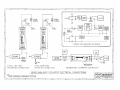
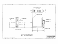
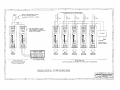
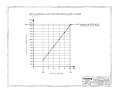
_________________________________________________________________
User's Manual: Series 340I
Model 340I DC-Powered Input Isolator
_________________________________________________________________
Table of Contents
Page
Introduction.......................................................................................................................... 2
Description ........................................................................................................................... 2
Specifications........................................................................................................................ 3
Installation ............................................................................................................................ 5
Calibration ............................................................................................................................ 7
General Maintenance............................................................................................................. 7
List of Drawings
Electrical Connections: (No. 4501-261). ............................................................................... 8
Dimensions: DIN Rail Mounting (No. 4501-262). ................................................................. 9
Electrical Connections: Power Supply Configurations (No. 4501-263) ................................ 10
Load Resistance Versus Supply Voltage (No. 4501-265) .................................................... 11
=================================
IMPORTANT SAFETY CONSIDERATIONS
==================================
It is very important for the user to consider the possible adverse effects of power, wiring,
component, sensor, or software failures in designing any type of control or monitoring system.
This is especially important where economic property loss or human life is involved. It is
important that the user employ satisfactory overall system design. It is agreed between the Buyer
and Acromag, that this is the Buyer's responsibility.
Acromag, Inc.
30765 South Wixom Road
P.O. Box 437
Wixom, Michigan 48393-7037, USA
Tel: (248) 624-1541
FAX: (248) 624-9234
Copyright 1993 Acromag, Inc. Printed in USA
Data and specifications subject to change without notice
8500-334-B93K008
- 1 -
Series 340I User's Manual
Process Current Input Isolator
_________________________________________________________________
_____________
INSTRUCTIONS: SERIES 340I
Process Current Input Isolator, DC Powered
INTRODUCTION:
These instructions cover the model types listed in Table 1 below. Supplementary sheets
are attached for units with special options or features.
Table 1:
A. Model Number Format : 340I-Input-Output-Mounting-Certification
B. Typical Model Number: 340I-C1-Y-DIN-NCR
Series
-Input
-Output
-Mounting
-Certification
340I
-C1
-Y
-DIN
-NCR
-Agency Approval 2
Notes (Table 1):
1. All units are factory calibrated for 4 to 20mA DC input and 4 to 20mA DC output
(no "-C" suffix needed).
2. Consult the factory for current information on agency (e.g. Canadian Standards
Association, etc.) approvals.
DESCRIPTION:
This DC powered input isolator accepts a 4 to 20mA DC input signal and provides an
isolated 4 to 20mA DC output signal. The isolator operates from a wide supply range, has a low
input burden, is RFI and EMI protected, and operates over a large temperature range with
excellent temperature coefficients, which minimize effects from the harsh plant environment.
The Series 340I is a DIN-rail mounted, process current isolator, designed to be used as
another functional component to provide the user with a modular approach to the varied
applications in the field. Unlike the Series 270I which is a two-wire loop-powered isolator, the
Series 340I is a three-wire isolator. That is, Series 340I Isolators require a separate power supply
connection, while the output signal and DC power share a common lead. The small package size,
low power requirements, and wide supply range offers maximum flexibility to the user. As a threewired DC powered device, it can also be used in critical applications that require the use of
redundant supplies. The Series 340I includes reverse polarity protection, current limiting, and
operates from a single 10V to 36V DC supply. In applications requiring only a single isolator, the
340I can use available DC power, or it can be wired to an optional Series 35PS power supply
module. The Series 35PS power supply module receives it's power from either 115V AC or 230V
AC. Applications requiring multiple isolators at a single location can more efficiently share a
single DC supply. The modular approach of this design and companion Acromag flat-pack
modules allows additional transmitters, input modules, isolators, and alarms to be easily integrated,
as required. See Drawing 4501-261 for a simplified Series 340I schematic.
- 2 -
Series 340I User's Manual
Process Current Input Isolator
_________________________________________________________________
_____________
Input wiring is inserted in the bottom of the unit, while output and power wiring is inserted
at the top of the unit. Screws to secure the wiring are located on the front panel. Connectors are
screw-clamp type and accept wire size up to #14 AWG.
Key 340I Features:
* True Galvanic (Transformer) Isolation
* Wide Ambient Temperature Range
* 1-Inch Wide DIN Mounted Package
* DC Powered, Wide Supply Range
* Allows Use of Redundant Supplies
* Low Input Burden (less than 1.5V)
* Highly Accurate and Stable
* No Load Trimming Required
* Current Limiting Included
* 0-500 ohm Load Range (15V supply)
SPECIFICATIONS:
Function: This DC powered isolator accepts a 4 to 20mA DC input, has input circuit isolation,
and provides a 4 to 20mA DC output. The output and DC power share a common terminal (3Wire connection). The Zero and Span trim adjustments utilize 15-turn potentiometers accessible
from the front of the unit. This isolator is DIN-rail mounted.
MODEL/SERIES: 340I- (Color coded with a white label)
INPUT:
-C1: 4 TO 20mA DC, with an input drop less than 1.5V at full-scale.
IMPORTANT: Input current must not exceed 100mA or damage to the unit
could occur.
Isolation: The input circuit is electrically isolated from the output and power circuits, allowing
the input to operate at up to 250V AC, or 354V DC off ground, on a continuous basis (will
withstand 1500V AC dielectric strength test for one minute without breakdown). This
complies with test requirements outlined in ANSI/ISA-S82.01-1988 for the voltage rating
specified.
OUTPUT:
-Y: 4 to 20mA DC. The output shares a common with the power supply.
NOTE: A voltage output option is not available for the Series 340I.
Instead, specify Model 350T-C1-Vx-NCR-C if this is a requirement
of your application.
Load Resistance Range Equation: The maximum load resistance is a function of available power
supply voltage as follows (refer to Drawing 4501-265):
R-Load (Maximum) = (Minimum VDC supply - 5.0V) / 0.02A
That is, with a 10.0V DC supply, R-Load = 0 to 250 ohms
with a 15.0V DC supply, R-Load = 0 to 500 ohms
with a 24.0V DC supply, R-Load = 0 to 950 ohms
- 3 -
Series 340I User's Manual
Process Current Input Isolator
_________________________________________________________________
_____________
Output Limiting: Output current is limited to 27mA, nominal.
Output Ripple: Less than +/-0.1% of the maximum output span.
Power: 10.0V to 36.0V DC, 27mA, nominal. The external DC power supply is connected
between the output (P) and (-) terminals. The output shares a common connection with
the power supply. The current specified is for rated supply inputs and full-scale output.
Supply current is limited to 34mA, maximum. Diode installed in isolator provides reverse
polarity protection.
IMPORTANT: Do not exceed 36V DC peak, to avoid damage to the isolator.
Power Supply Effect:
DC Volts: less than +/-0.001% of output span per volt DC change in supply.
60/120Hz Ripple: less than +/-0.01% of span per volt peak-to-peak of power supply
ripple.
Reference Test Conditions: Input/Output current: 4 to 20mA; output load 250 ohms; 77oF
(25oC); +15V DC supply.
Accuracy: Better than +/-0.1% of output span. This error includes the combined effects of
isolator repeatability, hysteresis, terminal point linearity and adjustment resolution. Does
not include sensor error.
Ambient Temperature Range: -13oF to 185oF (-25oC to 85oC).
Ambient Temperature Effect: Less than +/-0.003% of output span change per oF
(+/-0.005% per oC) over the ambient temperature range for reference test conditions. This
specification includes the combined effects of zero and span over temperature.
Bandwidth: -3dB at 50Hz, typical, with 500 ohm load.
Response Time: For a step input, the output reaches 98% of output span in 25ms, typical, with
500 ohm load.
Noise Rejection:
Normal Mode: -6dB at 60 Hz, typical, with 500 ohm load.
Common Mode: -95dB at 60Hz, typical, with 500 ohm load.
RFI Resistance: Less than +/-0.5%, of output span with RFI field strengths of up to 10V/meter
at frequencies of 27, 151 and 467 MHz.
EMI Resistance:
Less than +/-0.25% of output span effect with switching solenoids or
commutator motors.
Surge Withstand Capability (SWC): Input/Output terminations rated per ANSI/IEEE C37.901978. Unit is tested to a standardized test waveform that is representative of surges (high
frequency transient electrical interference), observed in actual installations.
- 4 -
Series 340I User's Manual
Process Current Input Isolator
_________________________________________________________________
_____________
Construction:
Printed Circuit Boards: Military grade FR-4 epoxy glass circuit board.
Terminals: Compression type, wire size 14 AWG maximum.
Case: Self-extinguishing NYLON Type 6.6 polyamide thermoplastic UL94V-2, color
black. General Purpose, NEMA Type 1 enclosure.
Printed Circuit Board Coating: Fungus resistant acrylic conformal coat.
Mounting Position: Position insensitive.
MOUNTING:
-DIN: General Purpose Housing, DIN-Rail Mount - "G" & "T" rails. "G" Rail (32mm),
Type EN50035; "T" Rail (35mm), Type EN50022. Refer to Drawing 4501-262 for outline
and clearance dimensions. Shipping Weight: 1 pound (0.45Kg) packed.
CERTIFICATION: Consult the factory for current information on the availability of agency
(e.g. Canadian Standards Association, Factory Mutual, etc.) approvals.
-NCR: No Certification Required.
INSTALLATION:
The isolator is packaged in a general purpose type of enclosure. Use an auxiliary enclosure
to protect against unfavorable environments and locations. Maximum operating ambient
temperatures should be within -13 to 185oF (-25 to 85oC) for satisfactory performance. If the has
been calibrated, it is ready for installation. Connect as shown in the connection diagram of
Drawing 4501-261. To verify calibration, refer to the "CALIBRATION" section.
Mounting:
Mount isolator assembly - refer to Drawing 4501-262 for DIN-rail mounting and clearance
dimensions.
DIN Rail Mounting: Using suitable fastening hardware, secure the
DIN rail to the designated mounting surface. A transmitter, can be
mounted to either the "T" or "G" Rail. Installation of the
transmitter to the rail depends on the type of DIN rail used. Units
can be mounted side by side on 1.0 inch centers, if required.
"T" Rail (35mm), Type EN50022: To attach a transmitter to this
style of DIN rail, angle the top of the unit towards the rail and
locate the top groove of the adapter over the upper lip of the rail.
Firmly push the unit towards the rail until it snaps solidly into
place. To remove a transmitter, insert a screwdriver into the lower
arm of the connector and pull downwards while applying outward
pressure to the bottom of the unit.
- 5 -
Series 340I User's Manual
Process Current Input Isolator
_________________________________________________________________
_____________
"G" Rail (32mm), Type EN50035: To attach a transmitter to this style of DIN rail,
angle the unit so that the upper groove of the adapter hooks under the top lip of the rail.
Firmly push the unit towards the rail until it snaps solidly into place. To remove a
transmitter, pull the lower part of the unit outwards until it releases from the rail, lift unit
from rail.
Electrical Connections:
The wire size used to connect the unit to the control system is not critical. All terminal
strips can accommodate wire from 14-26 AWG. Strip back the insulation 1/4 inch on each
lead before installing it into the terminal block. Input wiring may be either shielded or
unshielded twisted pair. Output wires should be twisted pair. Since common mode
voltages can exist on signal wiring, adequate wire insulation should be used and proper
wiring practices followed. It is recommended that output and power wiring be separated
from the signal wiring for safety, as well as for low noise pickup.
1. Power: Connect DC power supply per connection diagram, refer to Drawing 4501261. This isolator operates from DC power supplies only. Power supply voltage is not
critical and should normally be from 10 to 36V DC. The supply voltage must not
exceed 36V, or damage to the unit may occur. The power supply voltage must be
adequate to furnish full-scale current to the load(s). Rated variations in power supply
voltage or load resistance have negligible effect on isolator accuracy. Refer to "Power"
in the preceding "SPECFICATIONS" section for current requirements. The minus (-)
power supply lead and the minus (-) output lead share a common terminal. Power
connections are reverse polarity protected. Refer to Drawing 4501-263 for other
power supply configurations.
Ripple and Noise: Power supply ripple at 60Hz/120Hz is reduced at the load by the
isolator. The ripple at the load will be less than +/-0.01% of span per volt peak-topeak of power supply ripple.
2. Output: Connect output per connection diagram, refer to Drawing 4501-261. Load
range is a function of the module's power supply voltage; refer to "Output" in the
preceding "SPECIFICATIONS" section (see Drawing 4501-265). The output shares a
common with the power supply.
3. Grounding: The transmitter housing is plastic and does not require an earth ground
connection.
4. Input: Input is 4 to 20mA DC. Connect input per connection diagram, observe
proper polarity. NOTE: The input circuit is electrically isolated from the
output/power circuit allowing the input to operate up to 250V AC or 354V DC off
ground on a continuous basis.
- 6 -
Series 340I User's Manual
Process Current Input Isolator
_________________________________________________________________
_____________
CALIBRATION:
All units are calibrated and checked for proper performance at the factory before they are
shipped. The calibration example below is provided for reference.
Isolator - Adjustment Procedure:
Connect the isolator as shown in the recommended calibration connections of the
connection diagram (Drawing 4501-261). The input current source must be adjustable over the
entire input range of the unit and settable to an accuracy of 0.05% or better for proper results.
The Zero and Span adjustments are accessible on the front panel of the isolator, see
Drawing 4501-261 for location. The Zero and Span trim provided are not wide-range adjustable
and are suitable for fine tuning only. The screwdriver blade used to adjust the potentiometers
should not be more than 0.1 inch (2.54mm) wide.
Isolator - Calibration Example:
MODEL : 340I-C1-Y-DIN-NCR
Input : 4 to 20mA DC
Output: 4 to 20mA DC
1. Set the input source to 4.000mA. Adjust the Zero (Z) pot until the output reads
4.000mA DC (NOTE: If you have trouble reaching zero, you may have to first set the
span near 16.000mA).
2. Set the input source to 20.000mA. Adjust the Span (S) pot until the output reads
20.000mA DC.
3. Repeat steps 1 and 2 until the readings converge.
4. Check the midpoint by setting the input source to 12.000mA. The output should read
12.000mA +/-0.016mA DC. The instrument is now calibrated.
GENERAL MAINTENANCE:
The isolator contains solid-state components and requires no maintenance except for periodic
cleaning and calibration verification. When a failure is suspected, a convenient method for
identifying a faulty isolator is to exchange it with a known good unit. It is highly recommended
that a non-functioning isolator be returned to Acromag for repair, since Acromag makes use of
tested and burned-in parts, and in some cases, parts that have been selected for characteristics
beyond that specified by the manufacturer. Further, Acromag has automated test equipment that
thoroughly checks the performance of each isolator.
- 7 -