1
620 WinLoader,
Version 5.4,
User Manual
620-8982
Rev. A
620 WinLoader
620 WinLoader
Overview
LDR001
4/05
Copyright, Notices, and Trademarks
Printed in U.S.A. – © Copyright 2005 by Honeywell Inc.
Revision 01 – April 1, 2005
While this information is presented in good faith and believed to be accurate,
Honeywell disclaims the implied warranties of merchantability and fitness for a
particular purpose and makes no express warranties except as may be stated in
its written agreement with and for its customer.
In no event is Honeywell liable to anyone for any indirect, special, or
consequential damages. The information and specifications in this document are
subject to change without notice.
This document was prepared using Information Mapping® methodologies and
formatting principles.
Compaq® and Compaq Plus® are registered trademarks of Compaq Computer
Corp.
IBM AT® and PS2® are registered trademarks of IBM Corp.
Information Mapping is a trademark of Information Mapping, Inc.
Tandy 3000® and Tandy 4000® are registered trademarks of Tandy Corp.
Terminal Emulator® is a registered trademark of Honeywell, Inc.
Honeywell
Industrial Automation and Control
Automation College
1100 Virginia Drive
Fort Washington, PA 19034
ii
620 WinLoader Overview
4/05
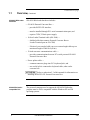
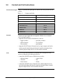
About This Publication
This manual presents:
•
Brief overview of 620 WinLoader;
•
Guidelines on how to use 620 WinLoader, Version 5.4, User
Manual;
•
General characteristics of 620 WinLoader hardware;
•
Overview of 620 WinLoader software, and
•
Description of compatible personal computers and printer options.
4/05
620 WinLoader Overview
iii
iv
620 WinLoader Overview
4/05
Table of Contents
SECTION 1 – INTRODUCTION TO 623 WINLOADER ..................................................... 1
1.1
1.2
1.3
Overview....................................................................................................... 1
623 WinLoader ............................................................................................. 2
623 WinLoader, Version 5.X, User Manual.................................................. 6
SECTION 2 – 623 WINLOADER HARDWARE ................................................................. 9
2.1
2.2
2.3
2.4
Overview....................................................................................................... 9
WinLoader Hardware Charactristics .......................................................... 11
Personal Computer and Printer Hardware Characteristics........................ 15
620 LC Networks........................................................................................ 16
SECTION 3 – 623 WINLOADER SOFTWARE ................................................................ 17
3.1
3.2
4/05
Overview..................................................................................................... 17
Software Characteristics ............................................................................ 18
620 WinLoader Overview
v
Tables
Table 2-1
Table 2-2
Table 2-3
Table 3-1
Table 3-2
vi
623-6020 Shipping Contents ..................................................................... 12
629-6019 Converter Specifications............................................................ 14
Personal Computer Specifications............................................................. 15
623 WinLoader Files .................................................................................. 20
623 WinLoader file extensions................................................................... 21
620 WinLoader Overview
4/05
Acronyms
ABC ............................................................................................. Asynchronous Byte Count
ASCII ................................................American Standard Code for Information Interchange
CIM .................................................................................Communications Interface Module
CPM ............................................................................................ Control Processor Module
CTS ................................................................................................................. Clear-to-send
DOS..................................................................................................Disk Operating System
EOS .................................................................................................................... End of Skip
I/O...................................................................................................................... Input/Output
JSR........................................................................................................ Jump to Subroutine
LAN ....................................................................................................... Local Area Network
LC ................................................................................................................ Logic Controller
MS ..........................................................................................................................MicroSoft
NSKD ............................................................................................Not Skip and Deenergize
NSKR ....................................................................................................Not Skip and Retain
OEM .................................................................................Original Equipment Manufacturer
PC...........................................................................................................Personal Computer
PID.............................................................................. Proportional, Integral, and Derivative
RTS ............................................................................................................ Request-to-send
RTU ....................................................................................................Remote Terminal Unit
SLM ......................................................................................................... Serial Link Module
SUB ..................................................................................................................... Subroutine
4/05
620 WinLoader Overview
vii
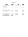
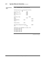
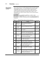
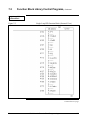
References
Publication
Title
Publication
Number
Binder
Title
Binder
Number
620-0043 Communications Interface
Module User Manual
620-8986
620 LC & S9000 Reference
MAS-8990
620 WinLoader Installation
LDR002
620 WinLoader
620-8983
620 WinLoader Implementation
LDR003
620 WinLoader
620-8983
620 WinLoader Programming
Reference
LDR004
620 WinLoader
620-8983
620 WinLoader Edit/Display Functions
LDR005
620 WinLoader
620-8983
620 WinLoader Function Blocks
LDR006
620 WinLoader
620-8983
620 WinLoader Documentation
Functions
LDR007
620 WinLoader
620-8983
620 WinLoader Networking Functions
LDR008
620 WinLoader
620-8983
620 WinLoader Utility Functions
LDR009
620 WinLoader
620-8983
620-6041 Terminal Emulator User
Manual
620-8989
viii
620 WinLoader Overview
4/05
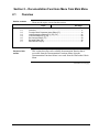
Section 1 – Introduction to 620 WinLoader
1.1
Overview
Section contents
These are the topics covered in this section:
Topic
1.1
1.2
1.3
Purpose of this
section
See Page
Overview ...................................................................................................... 1
620 WinLoader............................................................................................. 2
620 WinLoader, Version 4.X, User Manual ................................................. 6
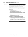
This section presents:
• Brief overview of 620 WinLoader, and
• Guidelines on how to use 620 WinLoader, Version 5.4, User Manual.
4/05
620 WinLoader Overview
1
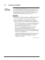
1.2
620 WinLoader
General description
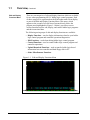
The 620 WinLoader is a software/hardware package that gives any
Windows compatible personal computer the capability to program and
monitor all 620 LCs using relay ladder logic. The WinLoader interfaces
with the 620 LC via an external converter.
The WinLoader includes a powerful software program that combines
menu-driven procedures and on-line monitoring with integrated
programming and documentation. This ladder logic program lets you
define the discrete control functions for your control strategy through
relay ladder logic using familiar logic elements such as contacts, coils,
timers, and counters.
• Refer to Section 2 of this manual for a complete overview of and
specifications for the 620 WinLoader hardware platforms, to include
—
623-6225 WinLoader, which comes with an RS232/422 Converter.
• In both hardware configurations, the WinLoader package consists of
the following:
one RS232/422 Converter and associated cables (623-6225).
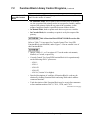
• Refer to Section 3 of this manual for a complete overview of the 620
WinLoader, version 5.4, software program, which is provided with both
hardware platforms.
620-6150A
Loader/Terminal
The 620-6150A Loader/Terminal is an industrially-hardened portable
hardware platform offered by Honeywell that has the latest version of
620 WinLoader software loaded on the internal hard disk.
• Comes with an RS232/422 External Converter Box to be installed
through 620-6150A Loader/Terminal's serial port.
• When power is applied, the unit immediately responds as a 620
WinLoader/Terminal.
• Refer to the separate documentation supplied with 620-6150A
Loader/Terminal for appropriate specifications and operating
procedures.
Continued on next page
2
620 WinLoader Overview
4/05
1.2
620 WinLoader,
How can I benefit
from WinLoader?
Continued
The 620 WinLoader software program offers a full variety of features
that turn your personal computer into an industrial programming device;
features and benefits of the package include:
• Easy to use:
– completely menu-driven,
– offers a series of "Help" screens, and
– minimal training required.
• Integrated programming/documentation:
– provides comprehensive link between ladder logic and
documentation.
• Stand-alone programming:
– may be used to develop ladder logic without being connected to a
620 Logic Controller (LC).
• On-line monitoring:
– monitors status of ladder logic as it is executing.
• Augmented Run Mode Programming:
– enables adding to or deleting from control program while 620 LC is
in Run/Program mode.
• Built-in Terminal Emulator:
– allows WinLoader to:
– accurately emulate Terminal mode of 620-50/51
Loader/Terminal, and
– program, configure, and/or transfer files to and from all
Honeywell 627 MiniCOP industrially-rated, microprocessorbased computing modules and related products.
• Time-saving Search functions:
– locates contacts by:
– line number,
– element type,
– element address, and/or
– element label.
• Extensive Documentation features:
– provides printout that includes additional descriptive data, such as –
– complete cross-references,
– unused addresses,
– conflicting addresses, and
– listings of all forms of text documentation.
Continued on next page
4/05
620 WinLoader Overview
3
1.2
620 WinLoader,
How can I benefit
from WIN Loader?,
continued
Continued
• Ladder logic addressing feature:
– uses 7-character label per ladder logic element in lieu of numeric
address when developing ladder logic.
• Free-format editing of documentation:
– allows you to –
– enter up to 20 lines of documentation (67 characters each line) via
ladder logic line and address;
– edit comments while editing or monitoring ladder logic.
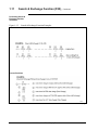
• Powerful Search & Exchange function:
– enables searching for and exchanging address and/or logic
instruction of an existing logic element every time it is found in the
ladder logic program;
– requires only a few keystrokes.
• Expanded Block editing functions:
– allows readdressing logic element in a block of ladder logic while
logic is being loaded into memory;
– up to eight different groups of addresses may be reassigned to
different address ranges.
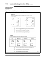
• Function Block programming features:
– allows creating ladder logic programs in modular format, which
offers the following benefits –
– reduces time required to assemble programs,
– helps standardize functions for special operations,
– makes programs easier to read and understand,
– saves time during testing since Function Blocks are pretested and
have fewer faults,
– makes ladder logic programs easy to generate, maintain, and
invoke, and
– also provides Function Block Library, which contains the ladder
logic of all available Honeywell Function Blocks.
• Flexible configuration feature:
– allows specifying different parameters for WinLoader software to
use for display, editing, and data storage functions based on
requirements of individual applications;
– offers an easy-to-use menu structure.
• Universal 620 LC interface:
– supports all 620 LCs for both on-line programming and monitoring
and stand-alone operations.
4
620 WinLoader Overview
4/05
1.2
620 WinLoader,
How can I benefit
from WinLoader?,
continued
Continued
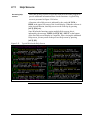
• Data Display function:
– permits monitoring up to 126 addresses regardless of locations in
program;
– offers ability to:
– read and write addresses (write to register address only),
– save 'snapshot' of system conditions, and
– create 'recipe file' for presetting register data values.
• External RS232/422 PC/620 LC converter device:
– may be used with any IBM-compatible personal computer that uses
Windows 2000 and Windows XP operating systems
• Multidrop 620 LC option:
– allows configuring network of up to thirty-one 620 LC devices and
connecting them to one WinLoader.
4/05
620 WinLoader Overview
5
1.3
620 WinLoader, Version 5.4, User Manual
How to use 620
WinLoader user
manual
The documentation supplied with the 620 WinLoader includes the
following user manuals; refer to each appropriate manual to access the
desired information or any particular operating procedure.
• 620 WinLoader Overview (LDR001) – which presents:
– brief overview of 620 WinLoader,
– guidelines on how to use 620 WinLoader, Version 5.4, User Manual,
– general characteristics of 620 WinLoader hardware,
– overview of 620 WinLoader software, and
– descriptions of compatible personal computers and printer options.
• 620 WinLoader Installation (LDR002) – which provides installation
procedures for:
– installing 629-6019 External Converter Box, which is provided with
620-6020 WinLoaders and 620-6150A Loader/Terminals, and must
be installed through a serial communications port of a personal
computer or the 620-6150A Loader/Terminal;
– installing cabling to RS232 serial printers;
– installing cabling to Serial Link Selector in redundant applications;
and
– installing WinLoader software, which is used 620-6020
WinLoaders.
• 620 WinLoader Implementation (LDR003) – which provides:
– general start-up procedure for 620 WinLoader
– overall description of WinLoader's Main Menu, to include
individual descriptions of Main Menu selections and descriptions
of each available function and sub-menu accessible from the Main
Menu; and
– overall description of WinLoader's Main Screen Display, to include
procedure for entering Main Screen Display and descriptions of
individual Main Screen Display components.
Continued on next page
6
620 WinLoader Overview
4/05
1.3 620 WinLoader, Version 5.4, User Manual,
How to use 620
WinLoader user
manual, continued
Continued
• 620 WinLoader Programming Reference (LDR004) – which presents:
– general overview of ladder logic entry and editing procedures which
are required for programming 620 LC instructions;
– general overview of the different categories of ladder logic
instructions which are available for 620 LCs;
– descriptions of each instruction in the 620 LC instruction set, to
include methods for entering each instruction; and
– descriptions of –
– 620 LC data representation,
– 16-bit error/status word used to indicate any conditions or errors
associated with programming operations, and
– conditional data handling, whereby conditional contacts are used
to control 620 LC arithmetic or comparison operations.
• 620 WinLoader Edit & Display Functions (LDR005) – which presents:
– general overview of WinLoader's ten different categories of edit and
display functions which are available for use when programming
620 LC ladder logic programs; and
– detailed overview of Auxiliary Function Menu functions, which are
accessible from the WinLoader's Edit & Display Functions Menu.
• 620 WinLoader Function Blocks (LDR006) – which presents:
– general guidelines and operating procedures for programming,
editing, displaying, and uploading/saving Function Blocks in an
WinLoader ladder logic control program; and
– procedures for implementing Honeywell's predefined Function
Block control programs.
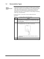
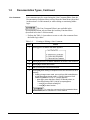
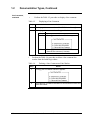
• 620 WinLoader Documentation Functions (LDR007) – which presents:
– general characteristics of documentation types used in ladder logic
programming with the 620 WinLoader, to include descriptions of
address labels and address descriptions, address comments, line
comments, and line numbers;
– descriptions of each available documentation function that is
accessible from the Documentation Functions Menu when the
Documentation Functions Menu is accessed from the WinLoader's
Main Menu; and
– descriptions of each available function that is accessible from the
Documentation Functions Menu when the Documentation Functions
Menu is accessed from the WinLoader's Auxiliary Function Menu.
Continued on next page
4/05
620 WinLoader Overview
7
1.3
620 WinLoader, Version 5.4, User Manual,
How to use 620
WinLoader user
manual, continued
Continued
• 620 WinLoader Networking Functions (LDR008) – which provides:
– detailed information on the following communications networks
which are available from Honeywell for the interconnection of 620
LCs and associated peripheral devices –
– Multidrop Loader Network
8
620 WinLoader Overview
4/05
Section 2 – 620 WinLoader Hardware
2.1
Overview
Section contents
These are the topics covered in this section:
Topic
2.1
2.2
2.3
2.4
3.1
3.2
Purpose of this
section
See Page
Overview ...................................................................................................... 9
WinLoader Hardware Charactristics.......................................................... 11
Personal Computer and Printer Hardware Characteristics ....................... 15
620 LC Networks ....................................................................................... 16
Overview .................................................................................................... 17
Software Characteristics ............................................................................ 18
This section presents:
• Detailed hardware description, specifications, and shipping contents of
620-6020 WinLoader;
• Additional hardware characteristics, to include:
– compatible personal computers,
– personal computer specifications, and
– printer options; and
• Available 620 LC networks.
Continued on next page
4/05
620 WinLoader Overview
9
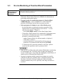
2.1
Overview,
Background
Continued
Depending on the type of control strategy you have configured for your
application, the WinLoader software program may be provided by
Honeywell as part of either of the following control system hardware
platforms:
• 620-60 WinLoader — provides a user-supplied DOS-compatible
personal computer with the capability to program and monitor all 620
Logic Controller CPMs, and is available in the following two versions:
– 620-6020 WinLoader, which comes with an RS232/RS422 External
Converter Box to be installed through a PC's RS232 serial
communications port.
– Refer to subsection 2.3 for additional hardware description,
specifications, and shipping contents of the 620-6020 WinLoader.
• 620-6150A Loader/Terminal — an industrially-hardened laptop
computer capable of all WinLoader functions.
– Comes with an RS232/422 External Converter Box to be installed
through the 620-6150A Loader/Terminal's serial port.
– Refer to the separate 620-6150A Loader/Terminal User Manual
(620-8940) for hardware description, system components, and
operating instructions for the 620-6150A Loader/Terminal.
10
620 WinLoader Overview
4/05
2.2
620-6020 WinLoader Hardware Characteristics
620-6020 WinLoader
hardware
620-6020 WinLoader hardware includes:
• 629-6019 External Converter Box —
– provides RS232/422 interface;
– must be installed through PC's serial communications port; and
– requires 5VDC, 250mA power supply.
• 10-foot Loader/Terminal cable (Model number 628-3000) —
– shielded cable that connects PC's interface card to Loader/Terminal
port on 620 CPM;
– if desired, you may also build your own custom length cable up to a
maximum length of 2000 feet (610m).
• 12-inch converter communications cable (Model number 628-6020) —
– provides communications between PC's serial port and 629-6019
External Converter Box.
• Power splitter cable (Model number 628-6021) —
– common connector plugs into PC's keyboard jack; and
– one end of split is connected to keyboard cable, other end to
converter box.
Continued on next page
4/05
620 WinLoader Overview
11
2.2
620-6020 WinLoader Hardware Characteristics,
620-6020 WinLoader
shipping contents
Continued
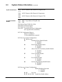
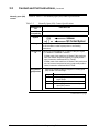
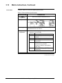
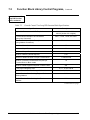
Refer to Table 2-1 below for shipping contents of the 620-6020
WinLoader.
• Site licenses are available for 620-6020 WinLoader.
• Site License Agreement (Model Number 620-8000) is optional.
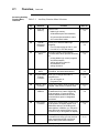
Table 2-1
620-6020 Shipping Contents
Part
Quantity
Description
RS232/422 Converter
1
• Model Number 629-6019
Shielded Cable
1
• 10-foot (3m)
• Model number 628-3000
PC/620 LC Converter
Communications Cable
1
• Model number 628-6020
PC/620 LC Converter Power
Cable
1
• Model Number 628-6021
620 WinLoader,
Version 5.4,
User Manual
Function Block Library
Specifications
1
Form 620-8983
1
Continued on next page
12
620 WinLoader Overview
4/05
2.2
620-6020 WinLoader Hardware Characteristics,
629-6019 Converter
Continued
The 629-6019 External Converter Box is provided with the 620-6020
WinLoader and must be installed through a serial communications port
of your personal computer.
• 629-6019 External Converter Box is factory-configured for
communications operation between personal computer's serial port and
Loader/Terminal port on CPM.
The interface port on the 629-6019 External Converter Box is a 9-pin
female sub-D connector with a tin-plated shell and a latching mechanism.
The interface port has both transmit and receive capabilities along with
clear-to-send and request-to-send control, and is used to communicate
with 620 LCs using the 10-foot Loader/Terminal cable; however, you may
wish to extend this length by constructing a cable according to the pin
assignments specified in 620 WinLoader Installation (LDR002). The 6296019 External Converter Box may operate at a maximum distance of 2000
feet (610m).
• Interface port is essential for 620-6020 WinLoader operation;
– 620-6020 WinLoader software will not communicate with a 620 LC
unless an interface port is installed in your personal computer.
Continued on next page
4/05
620 WinLoader Overview
13
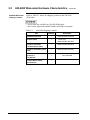
2.2
620-6020 WinLoader Hardware Characteristics,
629-6019 Converter
specifications
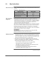
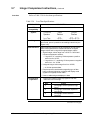
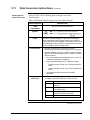
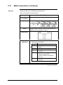
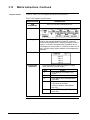
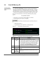
Refer to Table 2-4 below for specifications for the 629-6019 Converter
that is used with 620-6020 WinLoaders.
Table 2-2
629-6019 Converter Specifications
Specification
5-Pin Circular DIN
Male Connector
Description
Specification
Supply Voltage
Supply Input Current
9-Pin Subminiature
D-Type Male
Connector
9-Pin Subminiature
D-Type Female
Connector
Environmental
Specifications
14
Continued
Description
4.75-5.25 VDC @
0° to 60° C
(32° to 140° F)
250mA @
0° to 60° C
(32° to 140° F)
Specification
Maximum Cable Length
Interface Type
Input/Output Data Rate
Description
50 feet (15m)
RS232
Up to 9600 baud
Specification
Maximum Cable Length
Interface Type
Input/Output Data Rate
Description
2000 feet (610m)
RS422
Up to 9600 baud
Specification
Description
Operating Temperature 0° to 60° C
32° to 140°F
Humidity
5-95%
(non-condensing)
620 WinLoader Overview
4/05
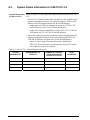
2.3
Personal Computer and Printer Hardware
Characteristics
620-60 WinLoadercompatible PCs
The personal computer used to support the 620-6020 WinLoader
program must be 100% compatible with the Windows 2000 and
Windows XP operating systems
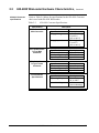
Personal computer
specifications
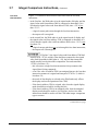
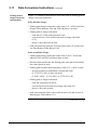
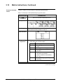
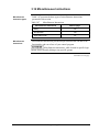
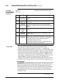
Refer to Table 2-3 for specifications for the WinLoader's personal
computer.
Table 2-3
Personal Computer Specifications
Specification
Personal Computer
Requirements
Description
Windows software and hardware-compatible
computers
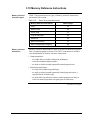
640K RAM (minimum)
Memory
Requirements
Mass Storage
Requirements
Category
Floppy-Only Systems
Hard Disk Systems
Printer options
4/05
Description
Disk capacity of
1.2M bytes or
greater.
1 floppy with 360K
bytes capacity or
greater and a
minimum of 1.2M
bytes of available
hard disk storage.
Any IBM-compatible printer will work with the WinLoader program.
620 WinLoader Overview
15
2.4
620 LC Networks
Available 620 LC
networks
The following communications networks are provided by Honeywell to
allow for the interconnection of 620 LCs and associated peripheral
devices:
• Multidrop Loader Network – allows a single WinLoader to be
multidrop-connected to up to thirty-one 620-12/1633/36 LCs via the
RS-485 electrical specifications using a version 4.1 (or greater)
WinLoader and a 3.1 (or greater) 620 LC CPM version.
Refer to 620 WinLoader Networking Functions (LDR008)
for detailed information on each of these communications networks.
16
620 WinLoader Overview
4/05
Section 3 – 620 WinLoader Software
3.1
Overview
Section contents
1.1
1.2
1.3
2.1
2.2
2.3
2.4
3.1
3.2
Purpose of this
section
These are the topics covered in this section:
Overview ...................................................................................................... 1
623 WinLoader............................................................................................. 2
623 WinLoader, Version 5.X, User Manual ................................................. 6
Overview ...................................................................................................... 9
WinLoader Hardware Charactristics.......................................................... 11
Personal Computer and Printer Hardware Characteristics ....................... 15
620 LC Networks ....................................................................................... 16
Overview .................................................................................................... 17
Software Characteristics ............................................................................ 18
This section presents:
• Overview of 620 WinLoader software,
• 620 WinLoader software specifications, and
• Listings of WinLoader files and file extensions.
4/05
620 WinLoader Overview
17
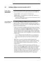
3.2
Software Characteristics
620 WinLoader
software
The software program 623-6226 is provided in a CD.
• Refer to the following manuals for more information on the main
620 WinLoader program:
– 620 WinLoader Implementation (LDR003)
– 620 WinLoader Programming Reference (LDR004)
– 620 WinLoader Edit & Display Functions (LDR005)
620 WinLoader
instruction set
Ten different categories of ladder logic instructions are available for use
by the 620 LC (to include contacts, coils, single/multiple data words,
timers, counters, sequencers, and other logic groups). Refer to 620
WinLoader Programming Reference (LDR004) for more information on
the 620 WinLoader instruction set.
620 WinLoader
documentation
functions
620 WinLoader documentation functions allow you to add labels,
descriptions, and comments to your ladder logic program and to program
printouts. Refer to 620 WinLoader Documentation Functions (LDR007)
for information on the documentation program.
18
620 WinLoader Overview
4/05
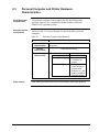
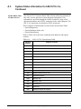
3.2
Software Characteristics,
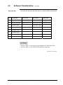
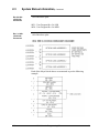
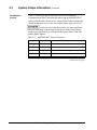
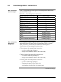
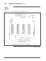
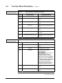
WinLoader files
Continued
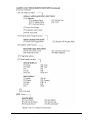
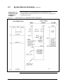
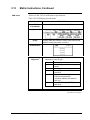
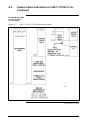
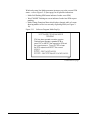
The following files from the WinLoader are found with the Install Shield
Sl.No .EXE Files
.CFG Files
.DAT Files
.HLP Files
SCR (LD) I.DAT LOADER.HLP
1
LOADER.EXE
LOADER.CFG
2
DCMNTED.EXE
MODCNFIG.CFG SCR (LD) R.DAT 620-0025.HLP
3
CONFIG.EXE
STR (LD) I.DAT
4
MODCNFIG.EXE
STR (LD) R.DAT
5
620-0025.EXE
6
620-0020.EXE
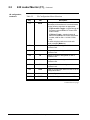
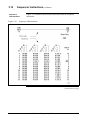
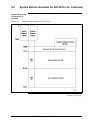
• Refer to Table 3-1 (next page) for descriptions of each of these files.
• Refer to Table 3-2 for a list of WinLoader file extensions.
Continued on next page
4/05
620 WinLoader Overview
19
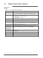
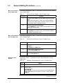
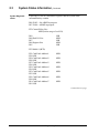
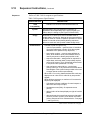
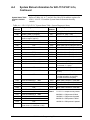
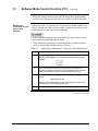
3.2
Software Characteristics, Continued
WinLoader files,
continued
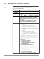
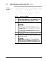
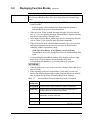
Table 3-1
620 WinLoader File Descriptions
File
CONFIG.EXE
DCMNTED.EXE
• Allows setting certain default conditions;
– Loader and Utility software read these conditions before execution.
• Allows editing:
– Address, skip, and subroutine labels,
– Descriptions,
– Address and line comments.
LOADER.CFG
Contains configuration data.
LOADER.EXE
Performs all ladder logic programming and some documentation functions.
LOADER.HLP
• Contains WinLoader Help Screen text;
– must be resident on same drive or directory from which WinLoader
software is loaded and executed.
MODCNFIG.EXE
Contains configuration utilities for 621-0020R and 621-0025R I/O Modules.
SCR (LD) I.DAT
SCR (LD) R.DAT
STR (LD) I.DAT
STR (LD) R.DAT
These files are necessary WinLoader screen and text support files.
621-0025.EXE
Supports RTDM
621-0020.EXE
Supports UAIM
621-0025.HLP
Help screens for RTDM
MODCNFIG.CFG
20
Description
Contains the configuration data for RTDM and UAIM.
620 WinLoader Overview
4/05
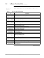
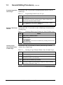
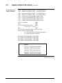
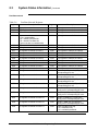
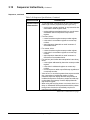
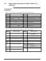
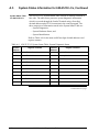
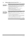
3.2
Software Characteristics,
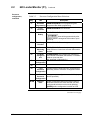
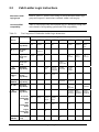
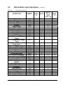
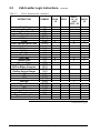
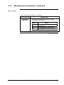
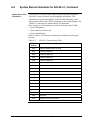
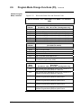
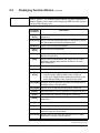
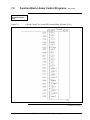
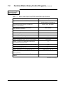
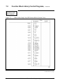
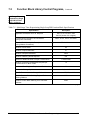
Refer to Table 3-2 below for a list of 620 WinLoader file extensions.
WinLoader file
extensions
Table 3-2
Continued
620 WinLoader File Extensions
File
Description
Filename.ACE
Logic Element Address Comment
Filename.BCE
Bit Read/Write Instruction Comment File
Filename.BLB
Bit Read/Write Instruction Label File
Filename.CFG
Loader Configuration Files
Filename.ERR
Ladder Logic Load Error File
Filename.FBL
Function Block Ladder File.
Filename.FBR
Function Block Register File
Filename.IOC
Input/Output Configuration
(620-11/12/14/16/36 LCs only)
Filename.JSR
Subroutine documentation (JSR, SUB, RTS)
Filename.LBL
Logic Element Address Labels
Filename.LCE
Ladder Logic Line Comments
Filename.LDR
Ladder Logic File
Filename.PIN
Printer Initialization File
Filename.PRC
Processor Configuration
(620-11/12/14/16/36 LCs only)
Filename.PRN
Printer File (stored to disk)
Filename.REG
Register Value File
Filename.RVR
Register Compare File
Filename.SKP
Skip Documentation (NSKR, NSKD, EOS)
Filename.VER
Logic and/or Data Verification Miscompare File
Filename.VUE
Data Display Files
Continued on next page
4/05
620 WinLoader Overview
21
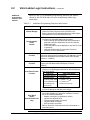
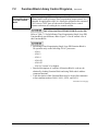
3.2
Software Characteristics,
WinLoader menu
selections
Continued
• Refer to Appendix A for an overview of WinLoader menu selections.
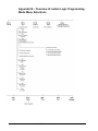
• Refer to Appendix B for an overview of ladder logic programming
mode menu selections.
22
620 WinLoader Overview
4/05
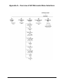
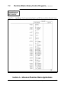
Appendix A – Overview of 620 WinLoader Menu Selections
4/05
620 WinLoader Overview
23
24
620 WinLoader Overview
4/05
4/05
620 WinLoader Overview
25
26
620 WinLoader Overview
4/05
4/05
620 WinLoader Overview
27
28
620 WinLoader Overview
4/05
4/05
620 WinLoader Overview
29
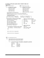
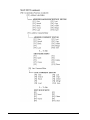
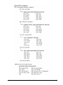
Appendix B – Overview of Ladder Logic Programming
Mode Menu Selections
30
620 WinLoader Overview
4/05
4/05
620 WinLoader Overview
31
32
620 WinLoader Overview
4/05
4/05
620 WinLoader Overview
33
34
620 WinLoader Overview
4/05
Industrial Automation and Control
Honeywell, Inc.
1100 Virginia Drive
Fort Washington, Pennsylvania 19034
620 WinLoader,
Version 5.4,
User Manual
620-8983
Rev. D
620 WinLoader
620 WinLoader
Installation
LDR002
4/05
Copyright, Notices, and Trademarks
Printed in U.S.A. – © Copyright 2005 by Honeywell Inc.
Revision 01 – April 01, 2005
While this information is presented in good faith and believed to be accurate,
Honeywell disclaims the implied warranties of merchantability and fitness for a
particular purpose and makes no express warranties except as may be stated in
its written agreement with and for its customer.
In no event is Honeywell liable to anyone for any indirect, special or consequential
damages. The information and specifications in this document are subject to
change without notice.
This document was prepared using Information Mapping® methodologies and
formatting principles.
IBM AT is a registered trademark of IBM Corporation
Information Mapping is a trademark of Information Mapping, Inc.
Terminal Emulator is a registered trademark of Honeywell, Inc.
Honeywell
Industrial Automation and Control
Automation College
1100 Virginia Drive
Fort Washington, PA 19034
ii
620 WinLoader Installation
4/05
About This Publication
This manual provides:
• Installation procedure for 629-6019 External Converter Box, which is provided with 620-6020
WinLoader and 620-6150A Loader/Terminals and must be installed through a serial
communications port of a personal computer or the 620-6150A Loader/Terminal.
• Additional WinLoader hardware installation procedures to include:
– Installing cabling to RS232 serial printers, and
– Installing cabling to Serial Link Selector in redundant applications.
• Installation procedure for WinLoader software, which is used with 620-6020 WinLoader.
4/05
620 WinLoader Installation
iii
Table of Contents
SECTION 1 – WINLOADER INSTALLATION OVERVIEW .............................................. 1
1.1
Overview ...................................................................................................... 1
SECTION 2 – HARDWARE INSTALLATION AND CONFIGURATION ........................... 3
2.1
2.3
2.4
Overview ...................................................................................................... 3
629-6019 External Converter Box ............................................................... 4
Cabling to RS232 Serial Printers ............................................................... 13
SECTION 3 – SOFTWARE INSTALLATION................................................................... 17
3.1
3.2
iv
Overview .................................................................................................... 17
WinLoader Installation ............................................................................ 18
620 WinLoader Installation
4/05
Figures and Tables
Figure 1
Rear View of 620-6150A Loader/Terminal .................................................... 4
Figure 2
Cable Construction.......................................................................................... 5
Figure 3
629-6019 Converter Cable Pin Assignments .................................................. 6
Figure 4
Communications Cable Connections .............................................................. 8
Figure 5
Loader/Terminal Cable Connections ............................................................ 10
Figure 6
Power Splitter Cable Connections ................................................................ 12
Figure 7
Cabling to RS232 Serial Printer Using 25-Pin Female Connector ............... 13
Figure 8
Cabling to RS232 Serial Printer Using Parallel/Serial Adapter 9-Pin Female
Connector. ...................................................................................................................................... 13
Figure 9
Recommended WinLoader Installation in a 620 Redundant Control System14
Figure 10
Recommended WinLoader Installation in a 620 Redundant Control System15
Table 1
4/05
Installing 629-6019 External Converter Box .................................................. 7
620 WinLoader Installation
v
Acronyms
620 LC ..................................................................................................620 Logic Controller
CPM ............................................................................................ Control Processor Module
CTS................................................................................................................. Clear-to-send
DIN...........................................Deutsche Industrie-Normen [German Industrial Standards]
DTR..................................................................................................... Data Terminal Ready
GND .......................................................................................................................... Ground
I/O ..................................................................................................................... Input/Output
LC ................................................................................................................Logic Controller
MS.......................................................................................................................... MicroSoft
PC .......................................................................................................... Personal Computer
PID ..............................................................................Proportional, Integral, and Derivative
RCV ......................................................................................................................... Receive
RTS.............................................................................................................Request-to-send
RXD .................................................................................................................Receive Data
SLS ........................................................................................................ Serial Link Selector
TXD.................................................................................................................Transmit Data
XMIT ....................................................................................................................... Transmit
vi
620 WinLoader Installation
4/05
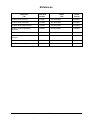
References
Publication
Title
Publication
Number
Binder
Title
Binder
Number
620 WinLoader Overview
LDR001
620 WinLoader
620-8983
620 WinLoader Implementation
LDR003
620 WinLoader
620-8983
620 WinLoader Programming
Reference
LDR004
620 WinLoader
620-8983
620 WinLoader Edit/Display Functions
LDR005
620 WinLoader
620-8983
620 WinLoader Function Blocks
LDR006
620 WinLoader
620-8983
620 WinLoader Documentation
Functions
LDR007
620 WinLoader
620-8983
620 WinLoader Networking Functions
LDR008
620 WinLoader
620-8983
620 WinLoader Utility Functions
LDR009
620 WinLoader
620-8983
620-6041 Terminal Emulator User
Manual
620-8989
4/05
620 WinLoader Installation
vii
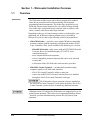
Section 1 – WinLoader Installation Overview
1.1
Overview
Introduction
The WinLoader includes a powerful software program that combines
menu-driven procedures and on-line monitoring with integrated
programming and documentation. This ladder logic program lets you
define the discrete control functions for your control strategy through
relay ladder logic using familiar logic elements such as contacts, coils,
timers, counters, and various other logic elements.
Depending on the type of control strategy you have configured for your
application, the WinLoader software program may be provided by
Honeywell as part of either of the following control system platforms:
• 620-60 WinLoader — provides a user-supplied Windows-compatible
personal computer with the capability to program and monitor all 620
Logic Controller CPMs, and is available in the following two versions:
– 620-6020 WinLoader, which comes with an RS232/RS422 External
Converter Box to be installed through a PC's RS232 serial
communications port.
– more complete hardware descriptions,
– a list of compatible personal computers that can be used with each
version, and
– a description of the 620 WinLoader software that is provided.
• 620-6150A Loader/Terminal — an industrially-hardened laptop
computer capable of all WinLoader functions;
– 620-6150A Loader/Terminal is sold as a spare part.
– comes with an RS232/422 External Converter Box to be installed
through the 620-6150A Loader/Terminal's serial port.
The WinLoader software program is factory-installed on
the 620-6150A Loader/Terminal; if your system includes a 620-6150A
Loader/Terminal, you do not have to install any additional software.
Although version 5.4 (and greater) WinLoaders are shipped and is set for
point-to-point operation. This section is not supporting Multidrop feature
, therefore, presents information that pertains only for point-to-point
operation.
4/05
620 WinLoader Installation
1
Continued on next page
1.1
Overview, Continued
620-6020 WinLoader
hardware
620-6020 WinLoader hardware includes:
• 629-6019 External Converter Box —
– provides RS232/422 interface;
– must be installed through PC's serial communications port; and
– requires 5VDC, 250mA power supply.
• 10-foot Loader/Terminal cable (628-3000) —
– shielded cable that connects External Converter Box to
Loader/Terminal port on 620 CPM;
– if desired, you can also build your own custom length cable up to a
maximum length of 2000 feet (610m).
• 12-inch converter communications cable —
– provides communications between PC's serial port and 629-6019
External Converter Box.
• Power splitter cable —
– common connector plugs into PC's keyboard jack; and
– one end of split is connected to keyboard cable, other end to
converter box.
Refer to subsection 2.3 of this manual for information on
installing the RS232/422 External Converter Box.
620-60 WinLoadercompatible PCs
2
The personal computer used to support the 620-6020 WinLoader
program must be 100% compatible with the Windows XP and 2K
operating systems
620 WinLoader Installation
4/05
Section 2 – Hardware Installation and Configuration
2.1
Overview
Section contents
These are the topics covered in this section:
Topic
2.1
2.2
2.3
Purpose of this
section
See Page
Overview ...................................................................................................... 3
629-6019 External Converter Box ............................................................... 4
Cabling to RS232 Serial Printers ............................................................... 13
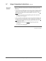
This section presents procedures for:
• Installing the 629-6019 External Converter Box, which is provided
with the 620-6020 WinLoader and must be installed through a serial
communications port of the personal computer or the 620-6150A
Loader/Terminal;
• Installing cabling from the WinLoader to typical RS232 serial printers;
and
• Installing cabling to a Serial Link Selector in a redundant control
system.
4/05
620 WinLoader Installation
3
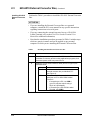
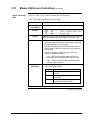
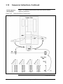
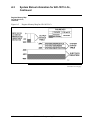
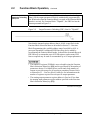
2.2
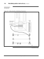
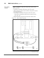
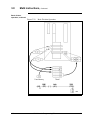
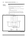
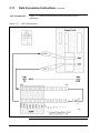
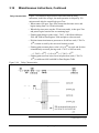
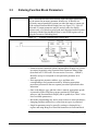
629-6019 External Converter Box
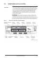
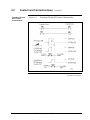
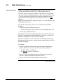
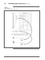
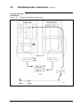
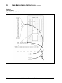
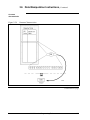
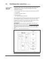
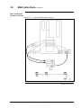
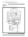
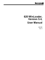
Description
The 629-6019 External Converter Box converts an RS232 signal from a
PC to an RS485 signal compatible with a device on an RS485 network in
a 620 LC system. It is provided with the 620-6020 WinLoader and the
620-6150A Loader/Terminal and must be installed through a serial
communications port of your personal computer or the 620-6150A
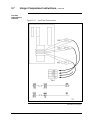
Loader/Terminal; Figure 1 (below) provides a rear view of the 6206150A Loader/Terminal.
The External Converter Box is factory-configured for
communications operation between either the personal computer's or the
620-6150A Loader/Terminal's serial port and the Loader/Terminal port on
the CPM; no further settings are required or can be made to the hardware.
Figure 1
Rear View of 620-6150A Loader/Terminal
Continued on next page
4
620 WinLoader Installation
4/05
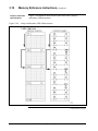
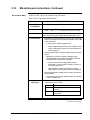
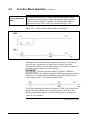
2.3
629-6019 External Converter Box, Continued
Interface port for
629-6019 External
Converter Box
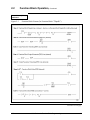
The interface port on the 629-6019 External Converter Box is a 9-pin
female sub-D connector with a tin-plated shell and a latching mechanism.
The interface port has both transmit and receive capabilities along with
clear-to-send and request-to-send control, and is used to communicate
with 620 LCs using the 10-foot Loader/Terminal cable; however, you
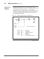
may wish to extend this length by constructing a cable according to the
pin assignments specified in Figures 2 and 3. The 629-6019 External
Converter Box can operate at a maximum distance of 2000 feet (610m).
The interface port is essential for 620-6020 WinLoader
operation; 620-6020 WinLoader software will not communicate with a
620 LC unless an External Converter Box is installed in your personal
computer.
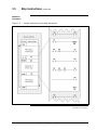
Figure 2
Cable Construction
Continued on next page
4/05
620 WinLoader Installation
5
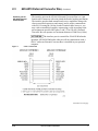
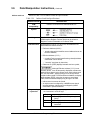
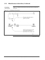
2.3
629-6019 External Converter Box, Continued
Interface port for 6296019 External
Converter Box,
continued
Figure 3
629-6019 Converter Cable Pin Assignments
Continued on next page
6
620 WinLoader Installation
4/05
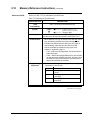
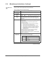
2.3
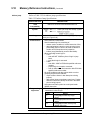
629-6019 External Converter Box, Continued
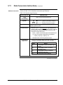
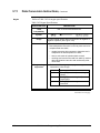
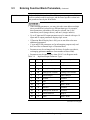
Installing 629-6019
External Converter
Box
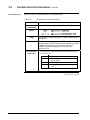
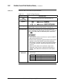
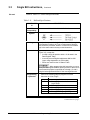
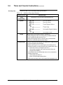
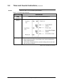
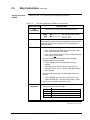
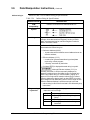
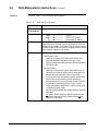
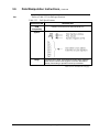
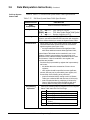
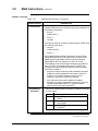
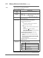
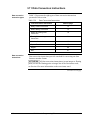
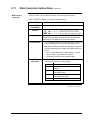
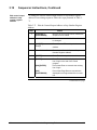
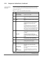
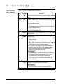
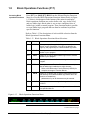
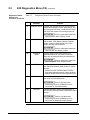
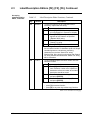
Perform the Table 1 procedure to install the 629-6019 External Converter
Box.
• If you are installing the External Converter Box on a personal
computer, consult the PC's users manual for any specific instructions
regarding connections to its serial ports.
• If you are connecting the external converter box to a 620-6150A
Loader/Terminal, refer to the 620-6150A Loader/Terminal User
Manual for additional information;
• Note that the installation procedure presented in Table 1 includes steps
which are generic in nature and can be applied to any personal
computer to which you are installing the External Converter Box.
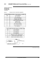
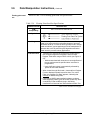
Table 1
Installing 629-6019 External Converter Box
Step
Action
1
Turn off the personal computer or 620-6150A Loader/Terminal,
remember to close any and all running applications programs, and
disconnect power cords from power source.
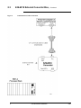
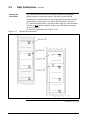
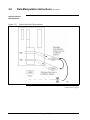
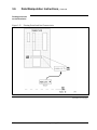
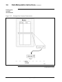
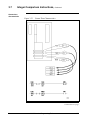
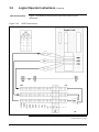
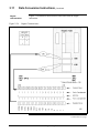
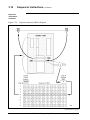
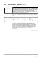
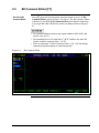
2
Install the 12-inch communications cable (shown in Figure 4) as
described below:
Step
2A
2B
4/05
Action
Attach one end of communications cable to
external converter box port labelled "PC"
(see Figure 4).
Attach other end of communications cable to
serial port on PC or 620-6150A Loader/
Terminal –
– if connecting to a PC, use COM 1;
(your PC may also require using a
25-pin to 9-pin adapter);
– if connecting to a 620-6150A Loader/
Terminal, use COM 2.
620 WinLoader Installation
7
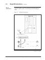
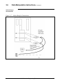
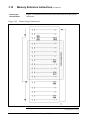
2.3
Figure 4
8
629-6019 External Converter Box,
Continued
Communications Cable Connections
620 WinLoader Installation
4/05
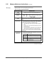
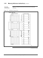
2.3
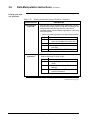
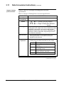
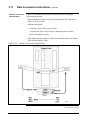
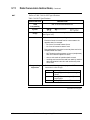
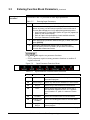
629-6019 External Converter Box, Continued
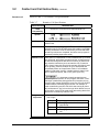
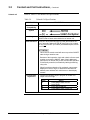
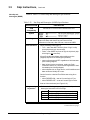
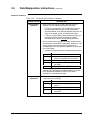
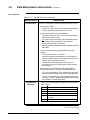
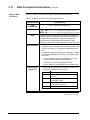
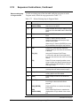
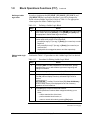
Installing 629-6019
External Converter
Box, continued
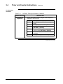
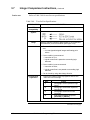
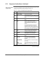
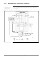
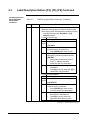
Table 1
Installing 629-6019 External Converter Box, Continued
Step
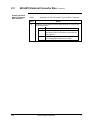
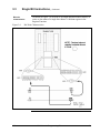
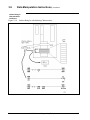
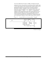
3
Action
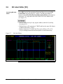
Install the 10-foot Loader/Terminal cable as shown in Figure 5 and
as described below:
Step
3A
3B
4/05
Action
Attach the cable's straight connector to the 9-pin
port labelled "620" on the external converter box
(see Figure 5);
Attach the angled connector of the cable to the
9-pin Loader/Terminal port on the CPM;
620 WinLoader Installation
9
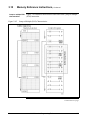
2.3
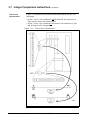
Figure 5
10
629-6019 External Converter Box, Continued
Loader/Terminal Cable Connections
620 WinLoader Installation
4/05
2.3
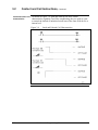
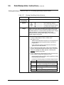
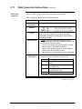
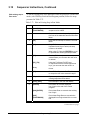
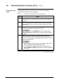
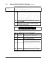
629-6019 External Converter Box, Continued
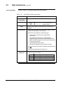
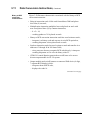
Installing 629-6019
External Converter
Box, continued
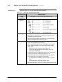
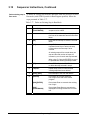
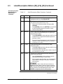
Table 1
Installing 629-6019 External Converter Box, Continued
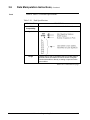
Step
4
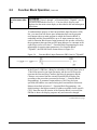
Action
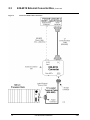
Provide a power connection as appropriate:
• If your PC is not capable of supplying 5VDC at 650mA through its
keyboard jack, use a compatible external power supply (not
supplied by Honeywell) that has been fitted with a 5-pin female
standard DIN connector.
It is your responsibility to determine if your PC has
a compatible keyboard port with +5VDC on the appropriate pins
and if it is capable of supplying the 650mA necessary to operate
the 629-6019 converter.
• If your PC is capable of supplying 5VDC at 650mA through its
keyboard jack, use the power splitter cable as follows
(see Figure 6):
Step
4A
4B
4C
4D
5
Action
Disconnect keyboard cable from PC.
Attach common power splitter cable to PC's
keyboard port.
Attach one of the split connectors to the
keyboard cable.
Attach other split connector to external
converter box port labelled "5VDC INPUT".
Reconnect power cords that were disconnected in step 1 of this
procedure.
To prevent the potentially damaging effects of
ground loop currents, ensure that the personal computer or 6206150A Loader/Terminal, and any connected devices (including the
620 LC system), are powered from a source that has a common
ground reference.
Continued on next page
4/05
620 WinLoader Installation
11
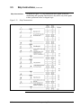
2.3
Figure 6
12
629-6019 External Converter Box, Continued
Power Splitter Cable Connections
620 WinLoader Installation
4/05
2.4
Cabling to RS232 Serial Printers
Installing cabling from
WinLoader to serial
printer
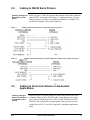
Figure 7
Figure 8
2.5
Cabling to RS232 Serial Printer Using 25-Pin Female Connector
Cabling to RS232 Serial Printer Using Parallel/Serial Adapter 9-Pin Female Connector.
Cabling to Serial Link Selector in Redundant
Applications
Installing cabling to
Serial Link Selector in
a redundant control
system
4/05
Refer to Figures 7 and 8 for pin-outs that illustrate WinLoader cabling to
typical RS232 serial printers; the Figure 7 configuration uses a 25-pin
female connector; the Figure 8 configuration illustrates an IBM PC AT
parallel/serial adapter 9-pin female connector.
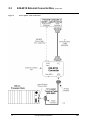
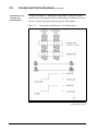
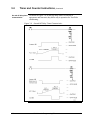
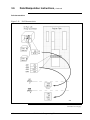
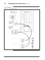
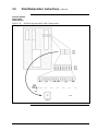
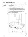
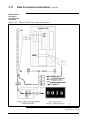
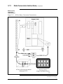
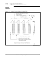
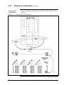
Refer to Figure 9 for cable wiring to a Serial Link Selector (SLS) in a
redundant control system. The first cable wiring diagram (next page)
shows cable wiring from the 620-6150A Loader/Terminal to the 6219928 SLS; the second cable wiring diagram (next page) shows cable
wiring from a 620 LC to an SLS (required for redundant applications
only).
620 WinLoader Installation
13
Figure 9
14
Recommended WinLoader Installation in a 620 Redundant Control System
620 WinLoader Installation
4/05
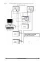
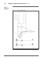
2.5
Cabling to Serial Link Selector in Redundant
Applications, Continued
Installing cabling to
Serial Link Selector in
a redundant control
system, continued
Figure 10
4/05
Recommended WinLoader Installation in a 620 Redundant Control System
620 WinLoader Installation
15
16
620 WinLoader Installation
4/05
Section 3 – Software Installation
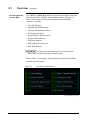
3.1
Overview
Section contents
These are the topics covered in this section:
Topic
3.1
3.2
Purpose of this
section
4/05
See Page
Overview .................................................................................................... 17
WinLoader Installation ............................................................................... 18
This section presents a procedure for installing the WinLoader software
program onto your personal computer. Note that the WinLoader is
already factory-installed on the 620-6150A Loader/Terminal; if your
system includes the 620-6150A Loader/Terminal, you do not have to
perform the installation procedure.
620 WinLoader Installation
17
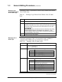
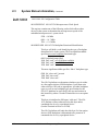
3.2
WinLoader Installation
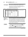
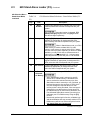
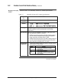
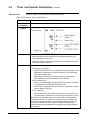
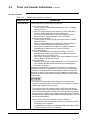
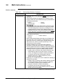
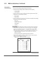
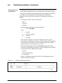
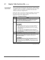
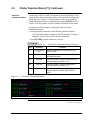
Un-installing Winloader:
620 WinLoader
un-installation
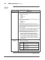
Step
1
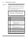
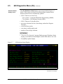
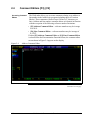
5.x installation provides you the option to uninstall any existing 5.x.
application. If you already have any 5.x application on your system, doubleclick the Win Loader installer. A confirmation screen is displayed as shown
below:
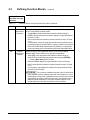
Action
To uninstall click Yes. You can either choose to uninstall or not. If you do not
want to uninstall, click No and the installer exits without making any changes.
Click Yes to uninstall the application. A confirmation screen appears as shown
below:
2
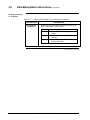
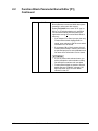
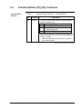
Click Finish. The un-installation is completed successfully.
3
18
Alternately, you can also use the Windows Add/Remove program feature to
uninstall 5.x. If you uninstall, you can install the latest by referring the
installation procedure.
620 WinLoader Installation
4/05
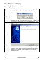
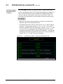
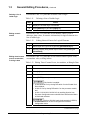
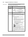
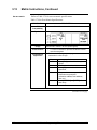
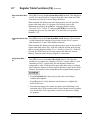
3.2 WinLoader Installation, Continued
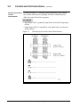
Installing Win Loader
620 WinLoader
Installation
Step
1
2
3
4/05
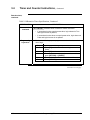
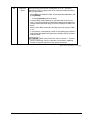
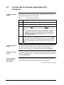
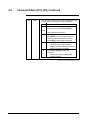
5.x installation does NOT uninstall 4.x or earlier DOS based
loader application. DO NOT use 4.x and 5.x on the same machine.
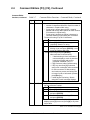
Follow this procedure to install WinLoader on your PC
Action
Insert the WinLoader CD in your PC.
Double-click the WinLoader Setup icon to display the 620 WinLoader Install
shield’s welcome screen.
Click Next to continue the installation.
620 WinLoader Installation
19
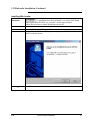
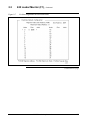
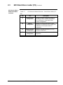
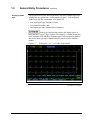
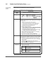
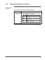
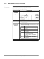
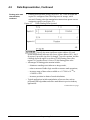
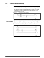
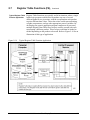
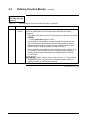
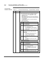
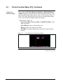
3.2 WinLoader Installation, Continued
The Customer Information screen is displayed. Enter the User Name and
Company Name and click Next.
4
20
620 WinLoader Installation
4/05
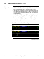
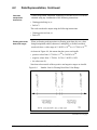
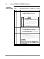
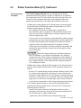
3.2 WinLoader Installation, Continued
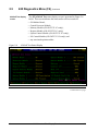
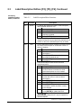
5
The Choose Destination Location screen is displayed. Click Browse and
navigate to the folder where you want to store the application files.
6
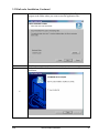
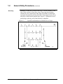
Click Next to continue with the installation.
The Installation Wizard Complete screen is displayed on successful
installation.
7
4/05
620 WinLoader Installation
21
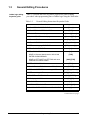
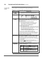
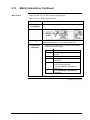
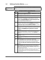
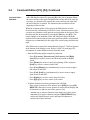
3.2 WinLoader Installation, Continued
8
9
Select Launch readme file to install the release notes in the folder where you
have installed the WinLoader application.
Click Finish to complete the installation.
Click Cancel at any point during the installation if you
want to cancel the installation and exit the 620 Win Loader Install shield.
Click Back if you want to return to the previous screen at any point
during the installation.
22
620 WinLoader Installation
4/05
Industrial Automation and Control
Honeywell, Inc.
1100 Virginia Drive
Fort Washington, Pennsylvania 19034
620 WinLoader,
Version 5.4,
User Manual
620-8983
620 WinLoader
620 WinLoader
Implementation
LDR003
4/05
Copyright, Notices, and Trademarks
Printed in U.S.A. – © Copyright 2005 by Honeywell Inc.
Revision 01 – April 01, 2005
While this information is presented in good faith and believed to be accurate,
Honeywell disclaims the implied warranties of merchantability and fitness for a
particular purpose and makes no express warranties except as may be stated in
its written agreement with and for its customer.
In no event is Honeywell liable to anyone for any indirect, special or consequential
damages. The information and specifications in this document are subject to
change without notice.
This document was prepared using Information Mapping® methodologies and
formatting principles.
IBM AT is a registered trademark of IBM Corporation.
Information Mapping is a trademark of Information Mapping, Inc.
Terminal Emulator is a registered trademark of Honeywell, Inc.
Honeywell
Industrial Automation and Control
Automation College
1100 Virginia Drive
Fort Washington, PA 19034
4/05
620 WinLoader Implementation
ii
About This Publication
This manual provides:
•
Overall description of WinLoader Main Menu, to include individual
descriptions of Main Menu selections and descriptions of each
available function and sub-menu accessible from the Main Menu; and
•
Overall description of WinLoader Main Screen Display, to include
procedure for entering Main Screen Display, and descriptions of
individual Main Screen Display components.
iii
620 WinLoader Implementation
4/05
Table of Contents
SECTION 1 – WINLOADER IMPLEMENTATION OVERVIEW ........................................ 1
1.1
1.2
Overview ...................................................................................................... 1
WinLoader Start-up...................................................................................... 2
SECTION 2 – WINLOADER MAIN MENU......................................................................... 1
2.1
2.2
2.3
2.4
2.5
2.6
2.7
2.8
2.9
Overview ...................................................................................................... 1
620 Loader/Monitor...................................................................................... 4
620 Stand Alone Loader(F2) ..................................................................... 18
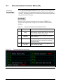
Documentation Functions (F3) .................................................................. 22
Password & Security Functions ................................................................. 25
I/O Configuration Utility (F5) ...................................................................... 29
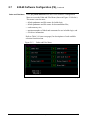
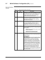
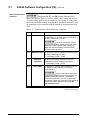
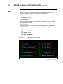
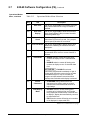
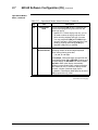
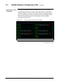
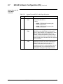
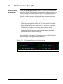
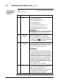
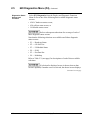
623-60 Software Configuration (F6) .......................................................... 30
Terminal Emulator (F7) .............................................................................. 46
Utility Functions (F8) .................................................................................. 47
SECTION 3 – WINLOADER MAIN SCREEN DISPLAY ................................................. 51
3.1
3.2
4/05
Overview .................................................................................................... 51
Main Screen Display .................................................................................. 52
620 WinLoader Implementation
iv
Figures
Figure 2-1
Figure 2-2
Figure 2-3
Figure 2-4
Figure 2-5
Figure 2-6
Figure 2-7
Figure 2-8
Figure 2-9
Figure 2-10
Figure 2-11
Figure 2-12
Figure 2-13
Figure 2-14
Figure 2-15
Figure 2-17
Figure 2-18
Figure 2-19
Figure 2-20
Figure 2-21
Figure 3-1
Figure 3-2
Figure 3-3
Figure 3-4
Figure 3-5
Figure 3-6
Figure 3-7
Figure 3-8
Figure 3-9
Figure 3-10
Figure 3-11
v
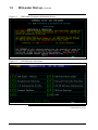
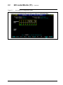
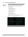
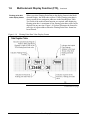
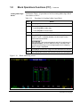
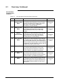
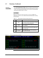
623 WIN Loader Main Menu ........................................................................ 2
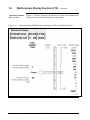
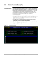
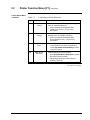
620 Selection Menu...................................................................................... 5
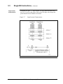
Accessing Processor Configuration Menu ................................................... 8
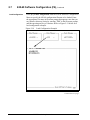
Accessing Multidrop Configuration Menu................................................... 11
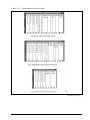
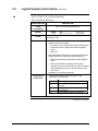
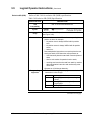
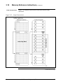
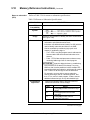
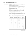
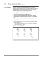
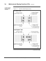
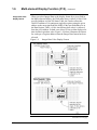
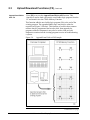
Accessing I/O Configuration Menu............................................................. 13
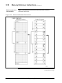
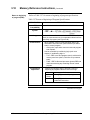
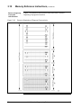
I/O Slot Assignments for 620-3691 Processor Rack.................................. 15
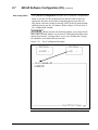
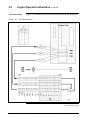
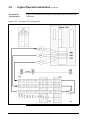
I/O Slot Assignments for Processor Racks ............................................... 16
620 Selection Menu - Stand-Alone Mode(F1-F5) ...................................... 18
620 Selection Menu - Stand-Alone Mode(F5-F8) ...................................... 20
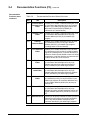
Documentation Functions Menu ............................................................. 23
Security Selection Menu ......................................................................... 25
623-60 Software Configuration Menu ..................................................... 30
Paths and Files Menu ............................................................................. 32
Operational Modes Menu........................................................................ 35
System Types and File Loads Menu....................................................... 38
Multidrop Node Names Menu ................................................................. 43
Load Configuration Example................................................................... 44
Save Configuration Example .................................................................. 45
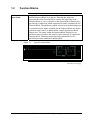
Exit .......................................................................................................... 48
Typical WinLoader Help Screen ............................................................. 49
Typical Title Page Display .......................................................................... 55
Name Check............................................................................................... 56
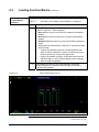
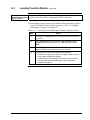
Loading Operation Messages ....................................................................57
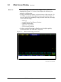
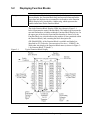
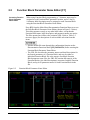
Main Screen Display .................................................................................. 58
Main Screen Display Banner......................................................................60
Main Screen Display Program Area........................................................... 61
9 x 5 x Ladder Logic Matrix ........................................................................ 62
Logic Group Selection Menu ...................................................................... 64
Edit and Display Functions......................................................................... 65
Program Area Integer Display................................................................. 66
Main Screen Display Status Line ............................................................ 67
620 WinLoader Implementation
4/05
Tables
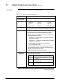
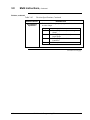
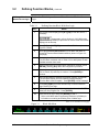
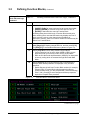
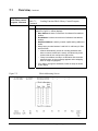
Table 1-1
Methods for Starting WinLoader .................................................................. 2
Table 1-2
Specifying Loader Configuration Filename.................................................. 5
Table 1-3
Entering Loader/Monitor Mode .................................................................... 6
Table 1-5
Entering Stand-Alone Mode......................................................................... 6
Table 2-1
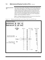
WinLoader Main Menu Selections ............................................................... 3
Table 2-2
620 Selection Menu Selections ................................................................... 6
Table 2-3
Processor Configuration Menu Selections .................................................. 9
Table 2-4
Multidrop Configuration Menu Selections.................................................. 10
Table 2-5
I/O Configuration Menu Selections ............................................................ 14
Table 2-6
620 Selection Menu Selections – Stand-Alone Mode (F1-F5) .................. 19
Table 2-7 620 Selection Menu Selections – Stand-Alone Mode (F5-F8)........................ 21
Table 2-8
Documentation Functions Menu Selections .............................................. 24
Table 2-9
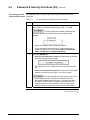
Accessing Password and Security Functions............................................ 26
Table 2-10
Changing the Password............................................................................. 27
Table 2-11
623-60 Software Configuration Menu Selections ...................................... 31
Table 2-12
Paths and Files Menu Selections .............................................................. 33
Table 2-13
Operational Modes Menu Selections......................................................... 36
Table 2-14
System Type and File Loads Menu Selections ......................................... 39
Table 2-15
Stand-Alone Parameters Menu Selections................................................ 41
Table 2-16
623-60 Software Configuration Menu Selections ...................................... 43
Table 3-1
Entering Main Screen Display Via [F1] 620 Loader/Monitor ..................... 53
Table 3-2
Entering Main Screen Display Via [F2] 620 Stand Alone Loader.............. 54
Table 3-3
Status Line Information .............................................................................. 68
Table 3-4
Periodic Statuses ....................................................................................... 71
4/05
620 WinLoader Implementation
vi
Acronyms
620 LC.................................................................................................. 620 Logic Controller
ABC ...............................................................................Asynchronous Byte Count Protocol
ANSI ......................................................................... American National Standards Institute
CAM .............................................................................................Controller Access Module
CGA................................................................................................. Color Graphics Adaptor
CIM ...................................................................................Communication Interface Module
CPM ............................................................................................ Control Processor Module
DOS..................................................................................................Disk Operating System
EIM .............................................................................................. Ethernet Interface Module
EPROM ......................................................... Erasable Programmable Read-Only Memory
IAC................................................................................. Industrial Automation and Controls
IMS ................................................................................. Interprocessor Messaging Service
I/O...................................................................................................................... Input/Output
IRQ ............................................................................................................Interrupt Request
KEYSW .................................................................................................................Keyswitch
LAN ....................................................................................................... Local Area Network
LC ................................................................................................................ Logic Controller
MAS......................................................................................... Modular Automation System
MS ..........................................................................................................................MicroSoft
NOP................................................................................................................. No Operation
OEM .................................................................................Original Equipment Manufacturer
PRG......................................................................................................................... Program
RAM ............................................................................................. Random Access Memory
RTDM ................................................................ Resistance Temperature Detector Module
RTS ............................................................................................................ Request-to-send
RTU ....................................................................................................Remote Terminal Unit
SIOM ......................................................................................................... Serial I/O Module
SLM ......................................................................................................... Serial Link Module
STF............................................................................................................. Self-Test Failure
SPM................................................................................................Software Program Mode
UAIM ....................................................................................Universal Analog Input Module
UMS .................................................................................................. User Memory Session
vii
620 WinLoader Implementation
4/05
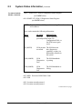
References
Publication
Title
Publication
Number
Binder
Title
Binder
Number
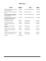
620-0048 & 620-0052 Data Collection
Modules User Manual
620-8980
620 LC & S9000 Reference
MAS 8990
620-12/1633/36 Logic Controller User
Manual
620-8964
620 Logic Controller
MAS 8991
621-0020R Universal Analog Input
Module and 620-0020 Configuration
Utility User Manual
621-8989
620 LC & S9000 Reference
MAS 8990
621-0025R Resistance Temperature
Detector Module and 620-0025
Configuration Utility Manual
621-8985
620 LC & S9000 Reference
MAS 8990
620 WinLoader Overview
LDR001
620 WinLoader
620-8983
620 WinLoader Installation
LDR002
620 WinLoader
620-8983
620 WinLoader Programming
Reference
LDR004
620 WinLoader
620-8983
620 WinLoader Edit & Display
Functions
LDR005
620 WinLoader
620-8983
620 WinLoader Function Blocks
LDR006
620 WinLoader
620-8983
620 WinLoader Documentation
Functions
LDR007
620 WinLoader
620-8983
620 WinLoader Networking Functions
LDR008
620 WinLoader
620-8983
620 WinLoader Utility Functions
LDR009
620 WinLoader
620-8983
620-6041
620-8989
4/05
620 WinLoader Implementation
viii
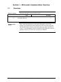
Section 1 – WinLoader Implementation Overview
1.1
Overview
Section contents
These are the topics covered in this section:
Topic
1.1
1.2
Purpose of this
section
4/05
See Page
Overview ...................................................................................................... 1
WinLoader Start-up...................................................................................... 2
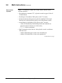
This section describes how to start-up the Winloader Loader from
prompt. Note that the procedures presented in this section assume that
the 620 WinLoader software program has been previously installed on
your PC. For information on how to install the 620 WinLoader software
program, refer to 620 WinLoader Installation (LDR002).
620 WinLoader Implementation
1
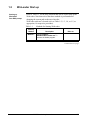
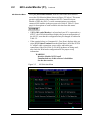
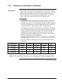
1.2
WinLoader Start-up
Starting up
WinLoader
from DOS prompt
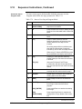
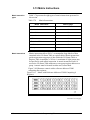
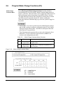
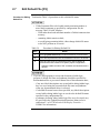
Refer to Table 1-1 for the three methods that can be used to start-up the
WinLoader. Note that each of the three methods is performed after
changing the current path to the one where the
WinLoader software is located (refer to Table 1-2, 1-3, 1-4, or 1-5, as
appropriate, for respective procedure).
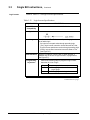
Table 1-1
Methods for Starting WinLoader
Start-up
Method
Method 1
Description
Refer to:
Select Program>
620Winloader>Loader.exe To
execute the loader program.
Continued on next page
2
620 WinLoader Implementation
4/05
1.2
WinLoader Start-up, Continued
Executing Loader
program
4/05
Click the WinLoader icon or navigate to the folder where you have
installed the 620 WinLoader and select the Loader.exe file.
620 WinLoader Implementation
3
1.2
WinLoader Start-up, Continued
Figure 1-1
WinLoader's Proprietary Information Screen
Figure 1-2
620 WinLoader Main Menu
Continued on next page
4
620 WinLoader Implementation
4/05
1.2
WinLoader Start-up,
Specifying Loader
configuration
filename upon startup
Continued
The ability to specify the configuration filename when starting the
WinLoader program enables you to change the environment in which the
software operates in order to accommodate multiple projects or other
functional variations of the program.
Perform the Table 1-2 procedure to specify a Loader configuration
filename.
Table 1-2
Step
Specifying Loader Configuration Filename Upon Start-up
Action
1
Execute the LOADER.EXE the software loads into PC's main
memory and begins executing by displaying proprietary information
screen (see Figure 1-1).
2
Press [ENTER] (after reading) to acknowledge and clear display.
Continued on next page
4/05
620 WinLoader Implementation
5
1.2
WinLoader Start-up,
Specifying Loader
mode of operation
upon start-up
Continued
Specifying the appropriate parameter upon start-up allows the
WinLoader to automatically enter either Loader/Monitor or Stand-Alone
mode.
• Refer to subsection 2.2 for description of Loader/Monitor mode and to
subsection 2.3 for description of Stand-Alone mode.
• By using Table 1-4 or 1-5 procedure –
– you may reduce number of keystrokes necessary to begin monitoring
or editing ladder logic program and can specify working
environment for those operations;
– Loader software exits directly to operating system without passing
through Main Menu; this allows commands to be used in any batch
files you create.
• Unless error occurs (such as missing documentation file), only
keystroke required to enter Loader/Monitor or Stand-Alone mode (after
commands are entered) is [ENTER] to acknowledge proprietary
information screen.
• If communication is established, Loader software examines
configuration file specified by FILENAME parameter, determines what
line to display initially, and if documentation files should be
automatically loaded.
Perform the Table 1-3 procedure to enter the Loader/Monitor mode:
Table 1-3
Step
Entering Loader/Monitor Mode Upon Start-up
Action
1
Perform Table 1-2 procedure steps 1 and 2.
2
Press [ENTER] (after reading) to acknowledge and clear display; a
menu appears. Select F1 in the menu options to enter the
Loader/Monitor mode and tries to establish communications with a
620 LC.
Perform the Table 1-5 procedure to enter the Stand-Alone mode:
Table 1-5
Step
6
Entering Stand-Alone Mode Upon Start-up
Action
1
Perform Table 1-2 procedure steps 1 and 2.
2
Press [ENTER] (after reading) to acknowledge and clear display; a
menu appears. Select F2 in the menu options to enter the StandAlone mode.
620 WinLoader Implementation
4/05
Section 2 – WinLoader Main Menu
2.1
Overview
Section contents
These are the topics covered in this section:
Topic
2.1
2.2
2.3
2.4
2.5
2.6
2.7
2.8
2.9
Purpose of this
section
See Page
Overview ...................................................................................................... 1
620 Loader/Monitor...................................................................................... 4
620 Stand Alone Loader(F2) ..................................................................... 18
Documentation Functions (F3) .................................................................. 22
Password & Security Functions ................................................................. 25
I/O Configuration Utility (F5) ...................................................................... 29
620-60 Software Configuration (F6) .......................................................... 30
Terminal Emulator (F7) .............................................................................. 46
Utility Functions (F8) .................................................................................. 47
This section presents:
• an overall description of the WinLoader Main Menu;
• individual descriptions of WinLoader Main Menu selections;
• descriptions of each available function and sub-menu accessible from
the WinLoader Main Menu.
Continued on next page
4/05
620 WinLoader Implementation
1
2.1
Overview, Continued
WinLoader main
menu
The WinLoader Main Menu is the primary entry vehicle into the
WinLoader software; it can be thought of as the "root menu" through
which all software-controlled 620 LC and WinLoader functions are
accessed.
The Main Menu displays eight selections which, when selected, display
submenus through which the various individual functions can be accessed;
except the functions F7 and F8.
Figure 2-1 illustrates the Main Menu display and Table 2-1 presents
functional descriptions of each individual Main Menu selection.
Figure 2-1
620 WinLoader Main Menu
Continued on next page
2
620 WinLoader Implementation
4/05
2.1
Overview, Continued
WinLoader main
menu, continued
Table 2-1
WinLoader Main Menu Selections
Key
Title
Description
F1
620 Loader/
Monitor
Permits communicating with 620 LC; can program, edit, document,
execute, and monitor ladder logic control programs residing in CPM.
F2
F3
F4
F5
F6
F7
F8
F10
4/05
Refer to
page:
4
620 Stand
Alone Loader
Allows you to program, edit, and document ladder logic control
programs without being connected to 620 LC; cannot execute
program or perform execution-based functions.
18
Documentatio
n Functions
Permits you to document ladder logic control programs without
entering 620 Loader/ Monitor or 620 Stand-Alone modes; can add
descriptive text to control programs.
22
Password &
Security
Functions
Permits you to assign security code to various system functions;
when attempt to access functions is made, system prompts for
security code before gaining access; password protects security
code function from unauthorized entry.
I/O
Configuration
Utility
Lists any previously installed I/O communications programs, which
are used to program and configure certain special function I/O
modules.
620-60
Software
Configuration
Allows you to preset numerous operational characteristics of
WinLoader software; user-configurable characteristics include:
• default paths
• floating point data handling
• file names
• WinLoader hardware
• personal computer options
operation
Not Supported in Winloader 5.4
Terminal
Emulator
Utility
Functions
Exit
25
29
30
46
Not Supported in Winloader 5.4
47
Allows you to quit WinLoader and return.
620 WinLoader Implementation
48
3
2.2
620 Loader/Monitor (F1)
620 Loader/Monitor
mode
Entering the 620 Loader/Monitor mode (by selecting [F1] 620
Loader/Monitor from the WinLoader Main Menu) permits you to
establish communications with a 620 Logic Controller system. From this
selection, you can program, edit, document, execute, and monitor ladder
logic control programs residing in the 620 LC's CPM.
Continued on next page
4
620 WinLoader Implementation
4/05
2.2
620 Loader/Monitor (F1),
620 Selection Menu
Continued
Press [F1] 620 Loader/Monitor from the WinLoader Main Menu to
access the 620 Selection Menu (shown in Figure 2-2 below). This menu
permits configuration of the connected 620 LC Control Processor
Module (CPM), the 620 LC's serial communications port, and any
connected I/O modules in the processor rack. Refer to Table 2-2 (next
page) for descriptions of each available selection from this menu.
• If [F1] 620 Loader/Monitor is selected and your PC is connected to a
620 LC, the 620 Selection Menu displays the present configuration of
the 620 LC; note that this configuration may be changed as outlined in
Table 2-2.
• If the warning below (or Command 66 – Port Error) displays after you
select [F1] Loader/Terminal from the Main Menu, check the PC/620
LC adapter cable connections, power cable, and loader port
connections if the 620-6150A or 620-6020 products are being used;
also check the WinLoader configuration file for proper set-up
information
WARNING
Interface Module NOT Found!
Unauthorized use of this software is forbidden.
See the above notice.
Figure 2-2
620 Selection Menu
Continued on next page
4/05
620 WinLoader Implementation
5
2.2
620 Loader/Monitor (F1),
620 Selection Menu,
continued
Table 2-2
Continued
620 Selection Menu Selections
Key
Title
Description
F1
Model Number
Displays model number of connected 620 CPM.
Regardless of connected
CPM, you may toggle [F1] to change model
number as desired; note that as model number
changes, [F2] Memory Size, [F3] Register Size,
and [F4] Real I/O Size also change
respectively.
F2
Memory Size
Toggling [F2] displays different amounts of
memory available for selected 620 CPM; select
desired memory size.
F3
Register Size
Toggling [F3] displays different amounts of data
registers available for selected 620 CPM; select
desired register size.
F4
Real I/O Size
Toggling [F4] displays various sizes of real I/O
available for selected CPM; select desired real
I/O size.
F5
Edit Processor
Configuration
Accesses Processor Configuration Menu to
allow editing of processor configuration; refer to
subsequent subsection titled Processor
Configuration.
F6
Edit I/O
Configuration
Accesses I/O Configuration Menu to allow
configuration of processor rack I/O slots; refer
to subsequent subsection titled I/O
Configuration.
F7
F8
Verify Processor Prompts you to enter a pathname to verify
processor configuration.
Configuration
Verify I/O
Configuration
Prompts you to enter a pathname to verify I/O
configuration.
620 Selection Menu software selections F5, F6, F7, and F8 apply only to
620-11, -12, -14, -1631, -1633, and -36 processor modules; other 620
CPMs (that is, 620-06, -10, -15, -25, and -35 processors) are configurable
only through hardware DIP switch selections as described in their
respective user manuals.
Continued on next page
6
620 WinLoader Implementation
4/05
2.2
620 Loader/Monitor (F1),
Processor
configuration
Continued
Press [F5] Edit Processor Configuration from 620 Selection Menu to
access Processor Configuration Menu (shown in Figure 2-3 - next page),
which allows you to edit, load, and save 620 LC's processor
configuration. Refer to Table 2-3 for descriptions of each available
selection from this menu.
• If [F5] Edit Processor Configuration is selected and PC is connected
to 620 LC, Processor Configuration Menu displays current 620 LC
configuration; configuration may be changed as outlined in Table 2-3.
• Press [F7] Verify Processor Configuration from the 620 Selection
Menu to verify your processor configuration once all configuration
entries have been made; this selection prompts you to enter a pathname
to verify the current processor configuration.
Continued on next page
4/05
620 WinLoader Implementation
7
2.2
Figure 2-3
620 Loader/Monitor (F1),
Continued
Accessing Processor Configuration Menu
Continued on next page
8
620 WinLoader Implementation
4/05
2.2
620 Loader/Monitor (F1),
Processor
configuration,
continued
Table 2-3
Processor Configuration Menu Selections
Key
Title
F1
Run Mode
Programming
F2
Force
Functions
F3
Continued
Description
ENABLE/DISABLE on-line programming and
Augmented Run Mode programming.
ENABLE/DISABLE force functions.
Scan with Low ENABLE/DISABLE scan with low battery.
Battery
Scan will be prevented only after
CPM keyswitch is changed to RUN mode or upon
power-up.
F4
Data Change
Function
ENABLE/DISABLE data change.
F5
Scan
Watchdog
Timer
ENABLE/DISABLE scan-loss (watchdog) timer;
halts CPM scan if scan time exceeds 160ms when
enabled.
F6
On Mode
Change I/O
will:
CLEAR/FREEZE local outputs upon transition to
SOFTWARE PROGRAM, PROGRAM, or DISABLE
mode or upon scan loss.
F7
Multidrop
Configuration
Not supported in Winloader 5.4
F9
Load
Processor
Configuration
Loads processor configuration file (Filename.PRC)
previously saved to Processor Configuration Menu.
F10
Save
Processor
Configuration
Saves processor configuration on a disk file (to path
and file specified).
ENTER
Return or
Enter
F8
Installs configuration data on Processor Configuration Menu to 620 LC's CPM; note that you must
verify that all selections are correct by pressing
[ENTER] before configuration is written to CPM.
Continued on next page
4/05
620 WinLoader Implementation
9
2.2
620 Loader/Monitor (F1),
Processor
configuration for
Multidrop Loader
Network
Continued
Press [F7] Multidrop Configuration (Presently Not Supported in
WinLoader 5.4) from Processor Configuration Menu to access the
Multidrop Configuration Menu (shown in Figure 2-4 - next page). This
menu is used to configure WinLoader to be part of a Multidrop Loader
Network with any connected 620 LC devices. Refer to Table 2-4 (below)
for descriptions of each of the available selections from this menu.
• Each 620 LC's CPM must be appropriately wired and configured (using
a standard point-to-point WinLoader connection) to operate in
Multidrop Loader Network mode and must be assigned a valid nodal
address; refer to 620-12/1633/36 Logic Controller User Manual (Form
620-8964) for more information on Multidrop Loader Network.
• Once Multidrop Loader Network has been set up, and connected
processors and WinLoader have been properly configured, you can
communicate to any particular 620 LC on the network through the
WinLoader simply by specifying the appropriate nodal address.
• Multidrop operation cannot be disabled while CPM is active; if CPM's
Multidrop nodal address is changed while Multidrop is active,
WinLoader will change its current nodal address at the same time so
that communications are not lost.
• Once configured for Multidrop operation, CPM will support both pointto-point and Multidrop Loader Network communications; this allows
you to remove any 620 LC from the network and connect it to a local
maintenance WinLoader.
Table 2-4
Multidrop Configuration Menu Selections
Key
Title
Description
F1
Multidrop
ENABLE/DISABLE Multidrop operation; default
is DISABLE.
F2
Nodal Address
Toggles sequentially to assign a specific nodal
address ([SHIFT] [F2] is reverse sequence).
Continued on next page
10
620 WinLoader Implementation
4/05
2.2
Figure 2-4
620 Loader/Monitor (F1),
Continued
Accessing Multidrop Configuration Menu
Continued on next page
4/05
620 WinLoader Implementation
11
2.2
620 Loader/Monitor (F1),
I/O configuration
Continued
Press [F6] Edit I/O Configuration from the 620 Selection Menu to
access the I/O Configuration Menu (shown in Figure 2-8 - next page).
This menu allows you to edit the 620 LC's processor rack I/O slots. Refer
to Table 2-8 for descriptions of each available selection from this menu.
• The processor rack I/O slots must be configured to the number of
points assigned to each slot according to the selections indicated in
Table 2-5. Note that all I/O slots in a processor rack will accommodate
8-, 16-, and 32-point I/O modules.
• Default setting for I/O Configuration Menu selections is 0; to edit
number of points per slot, select slot to be edited by using cursor
control keys to position highlighted edit field; then select F2 through
F5 for desired increments of 0, 8, 16, or 32 points. Press [ENTER] to
complete editing process and store data in 620 LC.
• 620-11, -12, -14, -1631, -1633, and -36 LCs must be in software or
keyswitch-selected PROGRAM mode when making I/O configuration
menu selections.
Continued on next page
12
620 WinLoader Implementation
4/05
2.2
Figure 2-5
620 Loader/Monitor (F1),
Continued
Accessing I/O Configuration Menu
Continued on next page
4/05
620 WinLoader Implementation
13
2.2
620 Loader/Monitor (F1),
I/O configuration,
continued
Table 2-5
Continued
I/O Configuration Menu Selections
Key
Title
Description
F1
Mode
Allows you to switch between slot edit and rack
edit modes; while software is in rack edit mode,
use the following selections as appropriate:
• [F2] Processor Toggle – toggles through all
processor racks available for current CPM
model number.
• [F3] Slave Toggle – toggles through all
slave racks available for current CPM model
number; valid for 620-11/14/1631 CPMs
only.
To retain selections and return to slot edit
mode, press [F1] Mode key.
F2
0
Assigns 0 points to designated I/O slot in
processor rack.
F3
8
Assigns 8 points to designated I/O slot in
processor rack.
F4
16
Assigns 16 points to designated I/O slot in
processor rack.
F5
32
Assigns 32 points to designated I/O slot in
processor rack.
F6
SLM
Assigns SLM module to designated I/O slot in
processor rack.
F9
Load
Loads I/O configuration data from disk file to I/O
Configuration Menu.
F10
Save
Saves configuration data to disk file.
ENTER
ENTER
Installs I/O configuration from menu to CPM.
Continued on next page
14
620 WinLoader Implementation
4/05
2.2
620 Loader/Monitor (F1),
I/O slot assignments
for I/O configuration
Figure 2-6
Continued
Slots A-N in the I/O Configuration Menu correspond with slots in the
620 LC processor rack. Figure 2-6 (below) specifies the I/O slot
assignment for each I/O module when you configure the 620-3691
Processor Rack by accessing the I/O Configuration Menu; Figure 2-10
(next page) shows I/O slot assignments for the 6203691/1690/1693/1695 processor racks.
I/O Slot Assignments for 620-3691 Processor Rack
Processor full rack
assignments
(620-3691 processor
racks)
In the 620-3691 Standard Processor Rack for the 620-36 CPM (shown in
Figure 2-10), I/O module slots A-F correspond directly with slots A-F in
the I/O Configuration Menu. Note that slots G-H are designated for the
power supply module, slots I-L are designated for the option modules,
and slots M-N are designated for the CPM; therefore, slots G through N
are not defined in the I/O Configuration Menu. Note also that slots E-F
can also be designated either for I/O modules or for Serial Link Modules
(SLMs) in 620-1633/-36 configurations.
• 620-3691, 620-1693, and 620-1695 processor racks do not support
more than one 627-1002R/-1003R MiniCOP Module.
• Slots E and F in 620-3691 processor rack, and slot H in 620-1690/1693 processor racks do not support 621-0012R ASCII
Communications Modules or 627-1002R/-1003R MiniCOP Modules.
Continued on next page
4/05
620 WinLoader Implementation
15
2.2
Figure 2-7
620 Loader/Monitor (F1),
Continued
I/O Slot Assignments for Processor Racks
Continued on next page
16
620 WinLoader Implementation
4/05
2.2
620 Loader/Monitor (F1), Continued
Processor full rack
assignments
(620-1690/-1693
processor racks)
In the 620-1690/1693 Processor Racks for the 620-36 CPM (shown in
Figure 2-10), I/O module slots A-H correspond directly with slots A-H in
the I/O Configuration Menu. Note that slots I-J are designated for the
power supply module, slots K-L are designated for option modules, and
slots M-N are designated for the CPM; therefore, slots I through N are
not defined in the I/O Configuration Menu. Note also that slot H may be
designated for either an I/O module or an SLM in 620-1633/36
configurations.
Processor half rack
assignments
(620-1695 processor
rack)
In the 620-1695 Augmented Processor Half Rack (shown in Figure 210), I/O module slots A-D correspond directly with slots A-D in the I/O
Configuration Menu. Note that slots E-F are reserved for the power
supply, and that slots G-H are reserved for the CPM. Note also that the
half rack does not support option modules or Serial Link Modules
(SLMs).
Serial I/O
assignments
620-1633/36 CPMs support serial I/O by designating a valid I/O slot for
the Serial Link Module (SLM) in the I/O Configuration Menu.
SIOM addresses must start at some address greater than
the highest address used in the last processor rack slot assigned; for
instance, if the highest address in slot F is 191, the SIOM addresses must
start at 192 or higher.
Verify I/O
configuration
4/05
Press [F8] Verify I/O Configuration from the 620 Selection Menu to
verify the I/O configuration; this selection prompts you to enter a
pathname to verify the current I/O configuration.
620 WinLoader Implementation
17
2.3
620 Stand Alone Loader (F2)
620 Selection Menu –
Stand-Alone Mode
Press [F2] 620 Stand Alone Loader from the WinLoader Main Menu to
access the 620 Selection Menu - Stand Alone Mode (shown in Figure 2-8
below). This menu allows you to designate a specific 620 CPM
configuration without actually being connected to the processor. Note
that you cannot execute a program or perform execution-based
functions while in the Stand-Alone mode. Refer to Table 2-9 (next
page) for descriptions of each available selection from this menu.
Figure 2-8
620 Selection Menu - Stand-Alone Mode (F1-F5)
Continued on next page
18
620 WinLoader Implementation
4/05
2.3
620 Stand Alone Loader (F2), Continued
620 Selection Menu –
Stand-Alone Mode,
continued
Table 2-6
F5)
620 Selection Menu Selections – Stand-Alone Mode (F1-
Key
Title
F1
Model
Number
Description
Toggling [F1] displays list of available 620 CPM model
numbers; select 620 CPM that corresponds with your
system.
As model number is changed, [F2]
Memory Size, [F3] Register Size, and [F4] Real I/O
Size also change respectively.
F2
Memory Size Toggling [F2] displays different amounts of memory
available (if appropriate) for designated 620 CPM;
select memory size that corresponds with your system.
When in Stand Alone mode, your PC's
RAM memory is used to emulate 620 LC's main
memory; main memory is area in which 620 LC stores
the user control program; depending on amount of RAM
available, you may not be able to emulate amount of
main memory in designated 620 LC – in these cases,
select largest memory size that your PC can emulate.
F3
Register Size Toggling [F3] displays different amounts of data
registers available (if appropriate) for designated 620
CPM; select size that corresponds with your system.
F4
Real I/O Size Toggling [F4] displays different amounts of real I/O
available (if appropriate) for designated 620 CPM;
select size that corresponds with your system.
F5
Permits you to reallocate your PC's RAM memory.
Free
Allocated
S-A Memory
• When Stand-Alone mode is selected, a specific
amount of PC's RAM memory is allocated for an
area to emulate the selected memory size; after
Stand-Alone mode is entered you can, if desired, go
back and change the size and type of CPM, which
may also change the required amount of main
memory which is being emulated; if size and type is
changed from one that requires a large amount of
PC's RAM memory for main memory emulation, the
Free Allocated Stand-Alone memory permits you to
reallocate your PC's RAM memory using the [F2]
function.
• Note that by performing this function, all ladder logic
and documentation that may currently reside in PC's
RAM memory will be lost; before using this function
you should save your current work.
Continued on next page
4/05
620 WinLoader Implementation
19
2.3
620 Stand Alone Loader (F2), Continued
620 Selection Menu –
Stand-Alone Mode,
continued
Press [ENTER] from the 620 Selection Menu – Stand-Alone Mode to
access a continuation of the 620 Selection Menu display (see Figure 2-12
below). This menu allows you to configure the designated 620 CPM
processor and any associated I/O slots in its rack. Refer to Table 2-10
(next page) for descriptions of each available selection from this menu.
• Note that you cannot execute programs or perform execution-based
functions while in the Stand-Alone mode.
• 620 Stand-Alone menu software selections F5, F6, F7, and F8 (shown
in Figure 2-12) apply only to 620-11, -12, -14, -1631, -1633, and -36
processor modules; other 620 CPMs (that is, 620-06, -10, -15, -25, and
-35 processors) are configurable only through hardware DIP switch
selections as described in their respective user manuals — note that the
F5 through F8 selections presented in Figure 2-12 are not available for
620-06, -10, -15, -25, and -35 processor modules.
Figure 2-9
620 Selection Menu - Stand-Alone Mode (F5-F8)
Continued on next page
20
620 WinLoader Implementation
4/05
2.3
620 Stand Alone Loader (F2), Continued
620 Selection Menu –
Stand-Alone Mode,
continued
Table 2-7
F8)
Key
Title
F5
Edit Processor
Configuration
Accesses Processor Configuration Menu to
allow editing of the processor configuration;
refer to subsection 2.2 description titled
Processor Configuration.
F6
Edit I/O
Configuration
Accesses I/O Configuration Menu to allow
configuration of processor rack I/O slots; refer
to subsection 2.2 description titled I/O
Configuration.
F7
F8
4/05
620 Selection Menu Selections – Stand-Alone Mode (F5Description
Verify Processor Prompts you to enter a pathname to verify
processor configuration.
Configuration
Verify I/O
Configuration
Prompts you to enter a pathname to verify I/O
configuration.
620 WinLoader Implementation
21
2.4
Documentation Functions (F3)
Documentation
Functions menu
Press [F3] Documentation Functions from the WinLoader Main Menu
to access the Documentation Functions Menu (shown in Figure 2-13
below). This menu permits you to document all elements in your ladder
logic program and to provide extensive labels, descriptions, and
comments throughout the program. Refer to Table 2-11 (next page) for
descriptions of each available selection from this menu; and refer to 620
WinLoader Documentation Functions (LDR007) for complete
explanations of each available function.
• If you are just beginning to create and document a ladder logic
program, the default file name and pathname should be specified for
documentation files to prevent accidental loss of documentation data.
• A pathname, defining where ladder logic files are to be stored, may be
specified in the Upload/Download Menu; the default file name and
pathname for documentation files may be specified using [F9] in the
Documentation Functions Menu.
• If any new labels and/or descriptions are created while editing ladder
logic, they are saved using the present default file name and pathname
when any documentation editor is selected.
• If you have not specified a default file name using [F9] in the
Documentation Functions Menu, any labels/descriptions created while
editing ladder logic are saved to the default file name specified in the
configuration file.
22
620 WinLoader Implementation
4/05
Figure 2-10
Documentation Functions Menu
Continued on next page
4/05
620 WinLoader Implementation
23
2.4
Documentation Functions (F3), Continued
Documentation
Functions menu,
continued
Table 2-8
Key
F1
F2
F3
24
Documentation Functions Menu Selections
Title
Description
Function Block Enables you to create 7-character labels and 3-line
Parameter Name by 9-character label descriptions for any Function
Blocks in your ladder logic program (refer to 620
Editor
WinLoader Function Blocks (LDR006) for
information on Function Blocks).
Address Label
Editor
Enables you to create 7-character labels and 3-line
by 9-character label descriptions for any logic
element address (0-8191) in your ladder logic
program.
Enables you to create comments of up to 20 lines
Address
Comment Editor (67 characters per line) for any logic element
address (0-8191) in your ladder logic program
(including those of Function Blocks).
F4
Line Comment
Editor
Enables you to create comments of up to 20 lines
(67 characters per line) which are related to ladder
logic lines (including those of Function Blocks) by a
reference number opcode added to each line during
programming; note that reference numbers and line
numbers do not have to be the same.
F5
Skip Label
Editor
Enables you to create 7-character labels and 3-line
by 9-character label descriptions for any logic
element skip instruction reference numbers (032767) included in your ladder logic program.
F6
Subroutine
Label Editor
Enables you to create 7-character labels and 3-line
by 9-character label descriptions for any logic
element subroutine instruction reference numbers
(0-255) included in your ladder logic program.
F7
Bit Comment
Editor
Enables you to create comments of up to 20 lines
(67 characters per line) for any bit location in your
ladder logic program; bit comment addresses may
be any register address (4096-8191) and any bit
value (0-15).
F8
Bit Label Editor
Enables you to assign 7-character labels and 3-line
by 9-character label descriptions for any logic
element bit location; bit label addresses can be any
register address (4096-8191) and any bit value (015).
F9
Edit Default File
Permits you to specify a default file name (of up to 8
characters) to be used to store all documentation
files for any defined labels, descriptions, and
comments included in your ladder logic program.
620 WinLoader Implementation
4/05
2.5
Password & Security Functions (F4)
Security Selection
menu
Press [F4] Password & Security Functions from the WinLoader Main
Menu to access the Security Selection Menu (shown in Figure 2-14 –
below). This menu allows you to assign a unique security code of up to
four numeric digits to each of the seven available functions – F1 through
F4 and F6 through F8 (as shown in the WinLoader Security Selection
Menu in Figure 2-14).
When an attempt to access any of these functions is made, the system
prompts the user for the security code before granting access. A password
protects the security code function itself from unauthorized entry.
• Security codes must be entered each time you attempt to use any of the
seven available functions (F1 through F4 and F6 through F8).
• Even when the WinLoader is in the Stand-Alone mode, functions F1,
F3, and F4 require proper security code entry; each of these functions
(mode change, forcing, and data change) may be protected by a unique
security code.
Figure 2-11
Security Selection Menu
Continued on next page
4/05
620 WinLoader Implementation
25
2.5
Password & Security Functions (F4), Continued
Accessing password
and security functions
Perform the Table 2-12 procedure to access password and security
functions.
Table 2-9
Accessing Password and Security Functions
Step
Action
1
Press [F4] on the WinLoader's Main Menu; since a password has not
been entered, a default password must be used — it is: 620.
If you have previously entered a password after
accessing the Security Selection Menu, the following prompt
displays:
• Note that Xs display as the password is entered.
• A user-selected password may be up to eight alphanumeric
characters (spaces are not permitted); after it is entered and
edited, verify that it is complete and correct.
2
Press the [ENTER] key.
• If an incorrect password is entered, an alarm beep is sounded
and the following message displays:
The display returns to the Main Menu after you press any other
key.
• If the correct password is entered, the Security Selection Menu
appears on the screen (see Figure 2-14, previous page).
Note that the default security code for each of the
seven functions shown in the Security Selection Menu (F1
through F4 and F6 through F8) is zero; if a security code other
than zero is entered (that is, 1-9999) and the edited security
codes are saved, you are prompted to enter the appropriate
security code prior to gaining access to the secured function.
Continued on next page
26
620 WinLoader Implementation
4/05
2.5
Password & Security Functions (F4), Continued
Changing password
Perform the Table 2-13 procedure to change the password as desired.
Table 2-10
Changing the Password
Step
Action
1
Select [F5] Edit Password from the Security Selection Menu (shown
in Figure 2-14); the present password or default password ("620" – if
no password has previously been assigned) is erased; the cursor is
positioned at the first character of the password.
2
Type in the new password.
3
Press [ENTER].
• Note that when you use a floppy disk as the default directory, you
must remove the write protect tabs before pressing [ENTER] to
save the information.
• If the default password is desired, press [ENTER] after pressing
[F5].
• If you enter a new password from any device by means of
Loader/Terminal software or any I/O Configuration Utility software,
the default password for all systems becomes the most recent
password.
4
Press [ENTER] to return to the WinLoader Main Menu.
If you use the [ESC] key to return to the Main
Menu, note that none of the new security codes or password
information will be saved, and the codes and passwords will remain
as they were when the Security Selection Menu was first selected.
Continued on next Page
4/05
620 WinLoader Implementation
27
2.5
Removing installed
security codes
Password & Security Functions (F4),
Continued
Perform the Table 2-14 procedure to remove any installed security code.
• To remove any password or security codes previously stored in your
system, either edit the information as described in Table 2-13 or use the
Table 2-14 procedure.
• Select the folder where the WinLoader program is installed and delete
passwd.fil to disable all security codes directly.
28
620 WinLoader Implementation
4/05
2.6
I/O Configuration Utility (F5)
Accessing I/O
Configuration Utility
Press [F5] I/O Configuration Utility from the WinLoader Main Menu
to list any previously-installed I/O Configuration Utility programs which
may be used to program and configure certain special function I/O
modules.
Configuration Utility programs available with the WinLoader include:
• 620-0020 Configuration Utility for 621-0020R Universal Analog
Input Module – this software, along with three jumpers on the 6210020R Universal Analog Input Module (UAIM), provide the sole
means for configuring the UAIM; refer to the separate 621-0020R
Universal Analog Input Module and 620-0020 Configuration Utility
User Manual (Form 621-8989) for more information on how to use this
configuration utility.
• 620-0025 Configuration Utility for 621-0025R Resistance
Temperature Detector Module – this software, along with some
external jumpers on the 621-0025R Resistance Temperature Detector
Module (RTDM), provide the sole means for configuring the RTDM;
refer to the separate 621-0025R Resistance Temperature Detector
Module and 620-0025 Configuration Utility User Manual (Form 6218985) for more information on how to use this configuration utility.
4/05
620 WinLoader Implementation
29
2.7
620-60 Software Configuration (F6)
Accessing the 620-60
Software
Configuration Menu
Press [F6] 620-60 Software Configuration on the WinLoader Main
Menu to access the 620-60 Software Configuration Menu (shown in
Figure 2-15 below). This menu allows you to preset the following
operational characteristics of the WinLoader software:
• default paths,
• file names,
• floating point data handling,
• personal computer options, and
• WinLoader hardware operation.
A virtual library of unique software configurations may be created for use
in various systems, environments, and situations that might arise in your
particular plant or facility. Refer to Table 2-15 (next page) for
descriptions of each available selection from this menu.
Figure 2-12
620-60 Software Configuration Menu
Continued on next page
30
620 WinLoader Implementation
4/05
2.7
620-60 Software Configuration (F6), Continued
Accessing the 620-60
Software
Configuration Menu,
continued
Table 2-11
620-60 Software Configuration Menu Selections
Key
Title
Description
F1
Paths and Files
Accesses Paths and Files Menu to enter default label,
ladder file, and path names as well as labels,
comments, and cache size maximums and 620 driver
information.
Subsequent
subsection titled
Paths and Files
Menu
F2
Operational
Modes
Accesses Operational Modes Menu to set modes of
operation for ladder logic display, programming, and
printer options.
Subsequent
subsection titled
Operational
Modes Menu
F3
Refer to:
System Type and Accesses System Type and File Loads Menu to assign Subsequent
type of system being used and sets file load
subsection titled
File Loads
conditions.
System Type and
File Loads Menu
F4
Stand-Alone
Parameters
Accesses Stand-Alone Parameters Menu which
enables you to set stand-alone configuration options
for stand-alone operation.
Subsequent
subsection titled
Stand-Alone
Parameters Menu
F5
Multidrop Node
Names
Accesses Multidrop Node Names Menu to assign a
Multidrop node name and address for Multidrop
Loader network operation.
Subsequent
subsection titled
Multidrop Node
Names Menu
F7
Load
Configuration
Loads a previously-saved configuration file to your
PC's RAM memory.
Subsequent
subsection titled
Load
Configuration
Example
F8
Save
Configuration
Saves current configuration to a file on your PC.
Subsequent
subsection titled
Save
Configuration
Example
F10
Exit
ESC
Escape
Exits the application.
Returns to WinLoader software via Main Menu,
Loader/Monitor, or Stand-Alone operation; if
Loader/Monitor or Stand-Alone are selected.
Continued on next page
4/05
620 WinLoader Implementation
31
2.7
620-60 Software Configuration (F6), Continued
Paths and Files Menu
Press [F1] Paths and Files from the 620-60 Software Configuration
Menu to access the Paths and Files Menu (shown in Figure 2-16 below).
This menu is used to enter:
•
•
•
•
•
default pathnames and file names for ladder logic,
default pathnames and file names for documentation files,
cache memory size,
maximum number of labels and comments for use in ladder logic, and
620 driver information.
Refer to Table 2-16 (next two pages) for descriptions of each available
selection from this menu.
Figure 2-13
Paths and Files Menu
Continued on next page
32
620 WinLoader Implementation
4/05
2.7
620-60 Software Configuration (F6), Continued
Paths and Files Menu,
continued
Table 2-12 Paths and Files Menu Selections
Key
Title
Description
F1
Ladder Path
Enables you to enter default pathname to be used
by LOADER and UTILITY to store ladder logic; can
be any previously defined directory pathname; if
left blank, directory from which LOADER was
executed becomes default directory.
F2
Ladder File
Enables you to enter default ladder logic file name
to be used by LOADER and UTILITY to store
ladder logic; default filename "620" is used if no
other filename is specified.
F3
Label Path
Enables you to enter default pathname (which can
be any previously defined directory pathname) to
be used by LOADER and UTILITY to store
documentation; if left blank, directory from which
LOADER was executed becomes default directory.
F4
Label File
Enables you to enter default label file name to be
used by LOADER and UTILITY to store all forms of
documentation.
– default filename "620" will be used if no other
filename is specified;
– this name will be overwritten if last 8
characters to title block are defined.
F5
Temp Path
Enables you to set up pathname where all
documentation files are to be stored temporarily for
display purposes.
Because these temporary files are
accessed repeatedly, speed of storage media has
significant effect on overall speed of software;
since these are "temporary" files, data storage
need not be permanent; it is recommended that a
RAM drive or RAM disk be created and specified
as temporary path; a RAM drive for this purpose
should not use system main memory (up to 400K)
and is recommended only if it can be established
in expanded memory beyond the 400K used by
system; a "temp" directory may be created from
root directory on a hard disk system; to use a
"temp" directory, first create directory on hard disk,
then, using configuration program, insert full path
and directory name.
Table 2-16 is continued on next page
4/05
620 WinLoader Implementation
33
2.7
620-60 Software Configuration (F6), Continued
Paths and Files Menu,
continued
Parameters F6, F7, and F8 from the Paths and Files
Menu (described in Table 2-16 below) allow you to control the amount
of main memory used for documentation in your system; if your system
has limited available memory, note that these parameters should be set to
the minimum values consistent with the amount of documentation to be
used.
Table 2-12 Paths and Files Menu Selections, Continued
Key
F6
Title
Description
Label Cache Size Enables you to enter number of labels to be
cached (that is, to be used in memory instead of
on disk); valid range is 10-200.
Cache is a temporary memory
area that allows faster access to frequently used
labels but occupies system main memory; the
larger the cache the faster the access and the
more memory to be used.
F7
Maximum Labels Enables you to specify maximum number of labels
for use in ladder logic program;
• valid range is 1000 – 16640.
F8
Maximum
Comments
Enables you to specify maximum number of
comments for use in a ladder logic program;
• valid range is 1000 – 24576.
F10
Driver Node
Enables you to select a network location from 0 to
31 (similar to nodal address) via serial port
communication.
Once multidropped Loader and
connected processors have been configured (via
Multidrop Node Names Menu – described in
subsequent subsection), you can communicate
through the Loader to a given 620 LC by specifying
a particular nodal address through this [F10]
Driver Node selection.
Continued on next page
34
620 WinLoader Implementation
4/05
2.7
620-60 Software Configuration (F6), Continued
Operational Modes
Menu
Press [F2] Operational Modes from the 620-60 Software Configuration
Menu to access the Operational Modes Menu (shown in Figure 2-17
below). This menu is used to set modes of operation for:
• ladder logic display options
• programming options
• printer options
Refer to Table 2-17 (next two pages) for descriptions of each available
selection from this menu.
Note that the following parameters on the Operational
Modes Menu may be changed from either LOADER or UTILITY:
• [F1] Auto-Clear
• [F2] Scan Time Display
• [F3] Output Check
• [F4] Full Time Detail
Figure 2-14
Operational Modes Menu
Continued on next page
4/05
620 WinLoader Implementation
35
2.7
620-60 Software Configuration (F6), Continued
Operational Modes
Menu, continued
Table 2-13
Operational Modes Menu Selections
Key
Title
F1
Auto-Clear
Can be set (toggled ON) so that display automatically clears each time line of logic is loaded or
inserted.
F2
Scan Time
Display
Can be set (toggled ON) to show 620 scan time
(from System Status Table) on status line while
monitoring ladder logic.
F3
Description
Duplicate Output Can be set (toggled ON) to check terminator
instructions for previous use and, if so, prompts
Check
user to specify whether OK to continue.
F4
Full Time Detail
Can be set (toggled ON) to display and/or edit a
detail block containing an element's label and
description.
F5
Beep
Can be set (toggled ON) so that audible beep
sounds when error occurs or current function is
finished.
F6
Float Width
• SINGLE selection causes all floating point
numbers to display as one 7-character data
field;
• DOUBLE selection causes all floating point
numbers to display as one 15-character data
field.
If DOUBLE is selected,
instructions programmed immediately to right of
floating point instruction must not have any data
associated with them; may be necessary to
program an NOP between instructions which
displays data if a double-wide display is selected.
F7
Printer
Characters
F8
Float Display
Mode
• STANDARD setting causes ASCII text
characters to be used to make up all logic
elements and vertical/horizontal lines on all
logic listings.
• DEC/EXP selection causes floating point
numbers to be in decimal form until number
being displayed exceeds ability of decimal form
to display it; display then automatically converts
to exponential form.
• EXP selection causes all floating point numbers
to be displayed in exponential form.
Table 2-13 is continued on next page
36
620 WinLoader Implementation
4/05
2.7
620-60 Software Configuration (F6), Continued
Operational Modes
Menu, continued
Table 2-13 Operational Modes Menu Selections, Continued
Key
Title
F9
Logic Group
Hold
Description
Can be set (toggled ON) to save 1 keystroke per
element when programming elements from the
same logic group;
• Applies to F1 Contact logic group only; you do
not need to select the logic group each time
before entering address and type of contact;
• You may program F3 [B2] and F4 PULL logic
groups to operate in same manner while in edit
mode by pressing and holding [CTRL] key
when F3 or F4 (or F1) is selected.
F10
Number of
Decimal Points
Enables you to fix location of decimal point by
specifying number of decimal digits displayed
when viewing floating point data;
• 1, 2, 3, 4, 5, or 6 digits
For example, if 3 decimal digits are specified and
Float Display Mode (F8) is DEC/EXP, floating point
numbers display as XXX.XXX until value exceeds
999.999 at which point display automatically
switches to exponential mode; numbers less than
.001 display as zero; if desired to display smaller
numbers, number of decimal digits may be
increased or Float Display Mode (F8) can be set to
EXP (exponential only) mode.
Continued on next page
4/05
620 WinLoader Implementation
37
2.7
620-60 Software Configuration (F6),
System Type and File
Loads Menu
Continued
Press [F3] System Type and File Loads from the 620-60 Software
Configuration Menu to access the System Type and File Loads Menu
(shown in Figure 2-18 below). This menu is used to select the particular
type of system being used and to set specific file load conditions. Refer
to Table 2-18 (next two pages) for descriptions of each available
selection from this menu.
Figure 2-15
System Types and File Loads Menu
Continued on next page
38
620 WinLoader Implementation
4/05
2.7
620-60 Software Configuration (F6), Continued
System Type and File
Loads Menu,
continued
Table 2-14 System Type and File Loads Menu Selections
Key
F2
Title
Description
Communications Enables you to specify how Loader will
communicate with 620 LC;
Port
• select:
– COM1 – if RS232/422 Converter (with
COM1) is being used
– COM2 – if RS232/422 Converter (with
COM2) is being used
F5
Edit Paths and
Files
Allows you to enable (toggle ON) or disable (toggle
OFF) ability to edit default path and file names
while in Loader software; if this parameter is set to
OFF and Software Configuration Menu is not
available, unauthorized personnel cannot change
pathnames and file names; note that this function
can be used to prevent accidental loss of programs
or documentation.
F6
Current Ladder
Line
Allows you to specify line number of logic to be
displayed on first entry into either Loader/Monitor
mode or Stand-Alone mode; each time Loader
software is executed, this line number is
overwritten to reflect line number displayed at time
of exit; this allows you to automatically return to
exact position in program loop being monitored.
Table 2-14 is continued on next page
4/05
620 WinLoader Implementation
39
2.7
620-60 Software Configuration (F6),
Continued
System Type and File
Loads Menu,
continued
Table 2-14 System Type and File Loads Menu Selections, continued
Key
Title
Description
F7
Ladder Logic
Load
Enables you to specify any of the following upon
entry to Stand-Alone mode (for Stand-Alone mode
only):
• AUTO LOAD – to load ladder logic files
automatically;
• NO LOAD – so that no logic is loaded upon
entry to Stand-Alone mode;
• PROMPT – to prompt user for verification
before any ladder logic files are loaded.
F8
Documentation
Load
Enables you to specify the following with regard to
documentation files (label/description, address
comment, line comment) upon entry to StandAlone mode (for Stand-Alone mode only):
• AUTO LOAD – to load documentation file
automatically;
• NO LOAD – so that no documentation file is
loaded upon entry to Stand-Alone mode;
• PROMPT – to prompt user for verification
before any documentation files are loaded.
Continued on next page
40
620 WinLoader Implementation
4/05
2.7
620-60 Software Configuration (F6), Continued
Stand-Alone
Parameters Menu
Press [F4] Stand-Alone Parameters from the 620-60 Software
Configuration Menu to access the Stand-Alone Parameters Menu (shown
in Figure 2-19 below). This menu enables you to set configuration
options for stand-alone Loader operation. Refer to Table 2-19 (below) for
descriptions of each available selection from this menu.
Table 2-15 Stand-Alone Parameters Menu Selections
Key
Title
F1
Model Number
F2
Memory Size
Enables toggling through list of available memory
sizes for selected 620 LC model number; note that
memory size will not change if selected 620 LC
does not offer a variable memory size (this
includes, 620-11, -12, -14, -1631, -1633, and -36
LCs); [SHIFT] [F1] allows reverse sequence.
F3
Register Size
Enables toggling through list of register sizes for
selected 620 LC model number; note that register
size will not change if selected 620 LC does not
offer a variable register size (this includes 620-11,
-12, -14, -1631, -1633, and -36 LCs); [SHIFT] [F1]
allows reverse sequence.
F4
Real I/O Size
Enables toggling through list of real I/O sizes for
selected 620 LC model number; note that real I/O
size will not change if selected 620 LC does not
offer a variable size (this includes 620-11, -12, -14,
-1631 (2048 I/O), -1633 (1024 I/O), and -36 LCs);
[SHIFT] [F1] allows reverse sequence.
Figure 2-16
Description
Enables toggling through list of 620 LC model
numbers to select one for Stand-Alone mode to
emulate; [SHIFT] [F1] allows reverse sequence.
Stand-Alone Parameters Menu
Continued on next page
4/05
620 WinLoader Implementation
41
2.7
620-60 Software Configuration (F6), Continued
Multidrop Node
Names Menu
Press [F5] Multidrop Node Names (Not supported in Winloader 5.4)
from the 620-60 Software Configuration Menu to access the Multidrop
Node Names Menu (shown in Figure 2-20). This menu is used to assign a
Multidrop node name and address for Multi-drop Loader network
operation. Refer to Table 2-20 for descriptions of each available selection
from this menu; also note the following:
• To configure WinLoader for Multidrop Loader network, make sure that
"620MD" is entered in Paths and File Menu [F9] 620 Driver File.
• Once multidropped Loader and connected processors have been
configured, you can communicate through Loader to 620 LC by
specifying nodal address on Paths and Files Menu [F10] Driver Node
selection.
• Once Loader is configured, Multidrop Node Name Menu displays
when you select [F1] 620 Loader/Monitor on WinLoader Main Menu;
Loader defaults to nodal address entered at [F10] in Paths and Files
Menu; by selecting [F1] Nodal Address on Multidrop Node Names
Menu, you can sequentially toggle the multidrop node you wish to
communicate with; [SHIFT] [F1] is reverse sequence.
• If node name doesn't exist for an address, address displays when you
press [ENTER]; Loader polls selected node to see if it responds; if it
does, Loader continues on to 620 Selection Menu as normal; Loader
reads multidrop node names from Loader software configuration file;
current node name displays on ladder logic EDIT/MONITOR screen
(in lower right-hand corner).
Continued on next page
42
620 WinLoader Implementation
4/05
Table 2-16
620-60 Software Configuration Menu Selections
Key
Title
F1
Nodal Address
Enables you to toggle sequentially to select
desired nodal address ([SHIFT] [F1] is reverse
sequence).
F2
Node Name
Enables you to enter node name for particular
nodal address selected (up to 8 characters).
Figure 2-17
Description
Multidrop Node Names Menu
Continued on next page
4/05
620 WinLoader Implementation
43
2.7
620-60 Software Configuration (F6), Continued
Load Configuration
Press [F7] Load Configuration from the 620-60 Software Configuration
Menu to specify the 620-60 configuration filename to be loaded. Enter
the appropriate file name in file name prompt that appears; note that you
may obtain a directory listing by entering "DIR" in the file name prompt,
and then pressing any key to continue. Refer to Figure 2-21 below for a
load configuration example.
Figure 2-18
Load Configuration Example
Continued on next page
44
620 WinLoader Implementation
4/05
2.7
620-60 Software Configuration (F6), Continued
Save Configuration
Press [F8] Save Configuration from the 620-60 Software Configuration
Menu to save the 620-60 configuration file that was edited. Enter the
appropriate file name in file name prompt that appears; note that you
may obtain a directory listing by entering "DIR" in the file name prompt,
and then pressing any key to continue. Refer to Figure 2-22 below for a
save configuration example.
When selected, this function prompts you to enter the file
name where the node address is to be stored; if that particular address has
already been entered, a prompt allows you to select whether the existing
file should be overwritten with the new data.
Figure 2-19
4/05
Save Configuration Example
620 WinLoader Implementation
45
2.8
Terminal Emulator (F7)
620-6041 Terminal
Emulator program
Press [F7] Terminal Emulator (Not supported in Winloader 5.4) from
the WinLoader Main Menu to load and execute the 620-6041 Terminal
Emulator software program.
Note that this description assumes that the 620-6041
Terminal Emulator software program has been included with your
system.
The 620-6041 Terminal Emulator program is a software package that
enables your PC to act as a "dumb" terminal. The American National
Standards Institute (ANSI)-compatible Terminal Emulator allows you to
perform peripheral communications/programming functions with serial
620 LC products. This includes program entry and data backup for the
following Honeywell products:
• 627-1002R/1003R MiniCOP
• 621-0012R ASCII Communication Module
• 621-0016R Controller Access Module (CAM)
Refer to the separate 620-6041 Terminal Emulator User Manual (Form
620-8989) for complete coverage of the Terminal Emulator software
program.
46
620 WinLoader Implementation
4/05
2.9
Utility Functions (F8)
620-60 Utility software
Press [F8] Utility Functions (Not supported in Winloader 5.4) from the
WinLoader Main Menu to load and execute the 620-60 Utility software.
Note that this description assumes that the 620-60 Utility
software has been included with your system.
620-60 Utility software comprises the following four main support
functions:
• Transfers ladder logic programs and documentation between the
WinLoader and cassette tape;
• Uploads, downloads, and appends ladder logic programs both to and
from a 620 LC through the 620-0048 Data Collection Module;
• Writes 620-06, -11, -14, and -1631 ladder logic programs to an
EPROM programmer in the Motorola S record format;
• Converts a formatted documentation data file to the 620-60 WinLoader
proprietary documentation file format and converts the proprietary files
to a formatted text file.
Refer to 620 WinLoader Utility Functions (LDR009) for complete
coverage of the 620-60 Utility software.
4/05
620 WinLoader Implementation
47
2.10
Exit (F10)
Exiting via main menu
selection
Press [F10] Exit from the WinLoader Main Menu to exit the user
program as shown in Figure 2-23 below.
Note that any previously-stored ladder logic programs and
documentation files are not affected if an abnormal exit occurs.
Figure 2-20
Exit
Continued on next page
48
620 WinLoader Implementation
4/05
2.11
Help Screens
Accessing help
screens
More than 60 Help screens are provided with the WinLoader program to
provide additional information about Loader functions. A typical Help
screen is presented in Figure 2-24 below.
A function with a Help screen is indicated by the words ALT-F10 =
HELP in the upper left corner of the Loader display. When the software is
in the desired function, that Help screen can be called up by pressing
[ALT] [F10] only.
Some WinLoader functions require multiple Help screens; this is
indicated by the message "HELP [ALT] [F10] = NEXT" at the bottom
of the first Help screen display in a sequence. After viewing the additional
Help screen, you may return to the previous Help screen by pressing
[ALT] [F9].
Figure 2-21
4/05
Typical WinLoader Help Screen
620 WinLoader Implementation
49
50
620 WinLoader Implementation
4/05
Section 3 – WinLoader Main Screen Display
3.1
Overview
Section contents
These are the topics covered in this section:
Topic
3.1
3.2
Purpose of this
section
See Page
Overview .................................................................................................... 51
Main Screen Display .................................................................................. 52
This section describes the WinLoader Main Screen Display, to include:
• general description of Main Screen Display,
• how to enter the Main Screen Display, and
• individual components of the Main Screen Display.
4/05
620 WinLoader Implementation
51
3.2
Main Screen Display
Entering Main Screen
Display
The WinLoader Main Screen Display may be entered from the Loader's
Main Menu through either the [F1] 620 Loader/Monitor or [F2] 620
Stand Alone Loader selection (shown in Figure 2-1). Note that both the
[F1] and [F2] selections from the WinLoader Main Menu are almost
identical, the primary difference between the two is the operating
characteristics of the path used to get to each function.
• [F1] 620 Loader/Monitor function requires that the PC running the
WinLoader software be connected to a 620 LC.
• [F2] 620 Stand Alone Loader function does not require that the PC
running the WinLoader software be connected to a 620 LC; rather, the
WinLoader's software uses the PC's memory to emulate the memory of
the 620 LC.
Continued on next page
52
620 WinLoader Implementation
4/05
3.2
Main Screen Display,
Entering Main Screen
Display via [F1] 620
Loader/Monitor
Continued
Perform the procedure presented in Table 3-1 to enter the WinLoader's
Main Screen Display by using the [F1] 620 Loader/Monitor function.
Note that this procedure requires that the PC running the WinLoader
software be connected to a 620 LC.
Table 3-1 Entering Main Screen Display Via [F1] 620 Loader/Monitor
Step
Action
1
Press [F1] 620 Loader/Monitor from WinLoader Main Menu to
access 620 Selection Menu.
2
Refer to Subsection 2.2 620 Loader/Monitor (F1) in Section 2 of this
manual for instructions on configuring 620 Selection Menu.
3
After 620 Selection Menu is configured as desired, press [ENTER] to
proceed to Title Page display (shown in Figure 3-1); refer to
subsequent subsection titled Title Page Display for additional
information.
If a ladder logic program currently resides in
memory, a prompt appears (after 620 Selection Menu configuration
is entered) asking whether you want to load ladder logic; if
nonexistent pathname and file name are entered, an error message
appears;
• if you respond yes (Y) to load ladder logic, you are then prompted
to enter the pathname and file name to be used;
• if you respond no (N) to the prompt, you will proceed directly to
the Title Page display.
Continued on next page
4/05
620 WinLoader Implementation
53
3.2
Main Screen Display,
Entering Main Screen
Display via [F2] 620
Stand-Alone Loader
Continued
Perform the procedure presented in Table 3-2 to enter the WinLoader's
Main Screen Display by using the [F2] 620 Stand Alone Loader
function. Note that this procedure does not require that the PC running
the WinLoader software be connected to a 620 LC.
Table 3-2 Entering Main Screen Display Via [F2] 620 Stand Alone
Loader
Step
Action
1
Press [F2] 620 Stand Alone Loader from WinLoader Main Menu to
access 620 Selection Menu.
2
Refer to Subsection 2.3 620 Stand Alone Loader (F2) in Section 2 of
this manual for instructions on configuring 620 Selection Menu.
3
After 620 Selection Menu is configured as desired, press [ENTER] to
proceed to Title Page display (shown in Figure 3-1); refer to
subsequent subsection titled Title Page Display for additional
information.
If a ladder logic program currently resides in
memory, a prompt appears (after 620 Selection Menu configuration
is entered) asking whether you want to load ladder logic;
• if you respond yes (Y) to load ladder logic, you are then prompted
to enter the pathname and file name to be used;
• if you respond no (N) to the prompt, you will proceed directly to
the Title Page display.
Continued on next page
54
620 WinLoader Implementation
4/05
3.2
Main Screen Display,
Title Page display
Continued
The Title Page display (shown in Figure 3-1 below) provides two blocks
of information:
• WinLoader software and 620 LC's CPM status, which indicate –
– firmware revision level of CPM,
– operating status (enabled, disabled, or secured) of software
configurable functions, and
– pass/fail result of CPM's Power-up Self Test.
• Ladder logic program title block, which (if a ladder logic program
currently resides in memory) indicates:
– program title,
– date program was written or last modified, and
– programmer's name.
Title Page display indicates a firmware revision level of
zero when WinLoader software is in 620 Stand Alone Loader mode.
Figure 3-1
Typical Title Page Display
Continued on next page
4/05
620 WinLoader Implementation
55
3.2
Main Screen Display, Continued
Name check
Pressing [ENTER] at the Title Page displays a message box (shown in
Figure 3-2 below) which asks if you wish to use the default file to load
any previously configured labels or comments from disk to be used in
your ladder logic program.
• Note that to right of title "Name Check!" current default file name
(assigned during software configuration) appears as shown in Figure 32.
• Refer to subsection 3.4 of 620 WinLoader Documentation Functions
(LDR007) for procedure for editing default file.
• Note that if a name is entered that is too long for title field so that it
extends into default file name field (last 8 characters as shown in
Figure 3-2), when program is loaded into CPM, WinLoader recognizes
that this field contains characters and incorrectly identifies them as
desired default file; these characters then appear in name check
displayed beneath title block;
– to correct situation, edit title block to remove or set last 8 characters
of title to default file name preferred;
– refer to subsection 3.5 of 620 Win Loader Documentation Functions
(LDR007) for procedure for editing title block.
Figure 3-2
Name Check
Continued on next page
56
620 WinLoader Implementation
4/05
3.2
Main Screen Display, Continued
Name check,
continued
When responding to the Name Check message box:
• if you respond yes (Y or [ENTER]) to load any previously configured
labels or comments, the software initiates the loading of labels, address
comments, and comment files that bear the default file name (see
Figure 3-3); a subsequent message displays during this operation which
indicates the status of the loading operation –
– Bad Load indicates that the file name specified does not exist or is
blank;
– No message indicates that the file name specified does exist, that it
contains data, and that it was successfully loaded.
After the loading operation is complete, the message "Done" displays
(as shown in Figure 3-3 below); press [ENTER] or [Esc] at this point
to call up the WinLoader Main Screen Display (shown in Figure 3-4).
• if you respond no (N or [Esc]) to the Name Check message box, the
loading procedure is aborted and the WinLoader Main Screen Display
appears immediately on the screen (shown in Figure 3-4).
Figure 3-3
Loading Operation Messages
Continued on next page
4/05
620 WinLoader Implementation
57
3.2
Main Screen Display, Continued
The WinLoader Main Screen Display (shown in Figure 3-4) is also
known as the Editor/Monitor Mode Menu because it is used to both
edit/program and monitor ladder logic control programs. Once you enter
the Main Screen Display, you must select the type of software operation
desired – PROGRAM or MONITOR:
Use [F11] Mode (that is, press [SHIFT] [F1] from WinLoader Main
Screen Display) to toggle between PROGRAM and MONITOR modes.
PROGRAM and
MONITOR modes
• WinLoader software normally follows keyswitch position of 620 LC,
so it will be in MONITOR mode for all keyswitch positions except
PROGRAM.
• When in 620 Stand Alone Loader mode, you are limited to PROGRAM
mode only, and may only create, edit, and document ladder logic
programs.
Figure 3-4
Main Screen Display
.
Continued on next page
58
620 WinLoader Implementation
4/05
3.2
Main Screen Display, Continued
PROGRAM and
MONITOR modes,
continued
• In PROGRAM mode, you may create and edit ladder logic programs
using available 620 logic elements and numeric addresses associated
with real and internal I/O points or registers;
– can also refer to on-line or off-line programming;
– if CPM's keyswitch is in RUN/PRGM position, on-line editing of
ladder logic program is permitted;
– on-line programming may be disabled or may include a security
code as specified in software configuration (refer to Subsection 2.5
Password & Security Functions (F4) in Section 2 of this manual for
more information of security codes);
– if CPM's keyswitch is in PRGM position, off-line editing of ladder
logic program is permitted.
• In MONITOR mode, you may monitor execution of a program in a
620 LC and program the processors' memory on-line.
– if CPM's keyswitch is in RUN, RUN/PRGM, or DISABLE position,
a real-time indication of TRUE/FALSE conditioning and data
handling of any executing ladder logic may be observed;
– editing of ladder logic program is not permitted.
Continued on next page
4/05
620 WinLoader Implementation
59
3.2
Banner
Main Screen Display, Continued
At the very top of the Main Screen Display a banner appears which
includes the following information (see Figure 3-5):
• Keystroke Functions – the following two keystroke functions are
available:
– ALT-F10=HELP — pressing [Alt] [F10] calls up on-line Help
screen for current display; refer to Subsection 2.12 Help Screens in
Section 2 of this manual for complete coverage of Help screens.
– ESC=Exit — pressing [Esc] brings up exit prompt to exit Main
Screen Display and return to 620 Selection Menu;
• Software Mode – indicates either of the following modes:
– PROGRAM mode
– MONITOR mode
• Ladder Logic Output Element Description area –
– displays three 9-character lines that describe output-type ladder
logic elements;
– if displayed line of ladder logic includes this form of documentation,
it is automatically displayed here;
– refer to 620 WinLoader Documentation Functions (LDR007) for
more information on documentation functions.
Figure 3-5
Main Screen Display Banner
Continued on next page
60
620 WinLoader Implementation
4/05
3.2
Main Screen Display, Continued
Program area
The center portion of the Main Screen Display is the program area (see
Figure 3-6); this is where ladder logic and supporting information are
displayed.
Figure 3-6
Main Screen Display Program Area
Continued on next page
4/05
620 WinLoader Implementation
61
3.2
Main Screen Display, Continued
Program area,
continued
The program area displays one line of ladder logic at a time; as shown in
Figure 3-7 below, a ladder logic line has a maximum size (matrix) of:
• 9 input-type logic elements in series,
• 5 parallel branches, and
• 1 output-type logic element (line terminator).
Some logic elements may require the display space of
more than one "typical" element; for example, a counter instruction is 2
elements wide and 3 elements high; in this case, only 7 input-type logic
elements may be placed in series with the counter.
Figure 3-7
9 x 5 x 1 Ladder Logic Matrix
Continued on next page
62
620 WinLoader Implementation
4/05
3.2
Main Screen Display, Continued
Program area,
continued
In addition to ladder logic, the program area is also capable of displaying
the following types of support information:
• Ladder logic documentation – to include:
– labels supplying a 7-character description of logic elements
associated with an address,
– detail providing an element's symbol, address, label, and a 27character description, and
– comment markers indicating that ladder logic line includes a
comment (which is a page of text used to describe the line).
• Current line number
• Execution status of ladder logic, which are messages indicating that
certain operations are taking place, such as:
– forced elements exist in program,
– current line is being skipped, and
– current line is not being scanned (executed).
Continued on next page
4/05
620 WinLoader Implementation
63
3.2
Main Screen Display, Continued
Logic Group Selection
Menu
The Logic Group Selection Menu (highlighted in Figure 3-8 below)
provides access to the various instructions (elements) used to program
ladder logic control programs. This menu appears directly below the
program area, and is the first of several lines of menus and information
located at the bottom of the WinLoader's Main Screen Display.
There are ten menu selections available through the Logic Group
Selection Menu, and each is identified by function keys F1 through F10.
Each logic group selection contains a number of similar elements
(instructions) which are used to program your ladder logic control
program.
Pressing a particular function key (F1 through F10) will cause a
corresponding menu to display which illustrates the particular logic
elements contained in the selected group. The new menu displays in the
space directly below the Logic Group Selection Menu, which then
disappears while the new menu is open.
Refer to 620 WinLoader Programming Reference (LDR004) and 620
WinLoader Edit/Display Functions (LDR005) for more complete
coverage of WinLoader ladder logic elements, available instructions, and
the Logic Group Selection Menu.
Figure 3-8
Logic Group Selection Menu
Continued on next page
64
620 WinLoader Implementation
4/05
3.2
Main Screen Display, Continued
Edit and Display
Functions Menu
The Edit and Display Functions Menu (highlighted in Figure 3-9 below)
provides access to various functions used to edit, display, and control
ladder logic programs and their associated data. This menu appears
below the Logic Group Selection Menu.
There are ten menu selections available through the Edit and Display
Functions Menu, and each is identified by function keys F11 through F20.
Many Edit and Display Functions contain a menu of available operations
for the particular function selected; others directly initiate the function
that they represent.
Pressing a particular function key (F11 through F20) will either display
another menu which contains accessible operations for the selected
function, or will initiate the desired function directly. For example, the
F12—AUX (Auxiliary) function displays a second menu containing the
available auxiliary operations, while the F16—LIST function immediately
begins listing the line contained in the control program.
Refer to 620 WinLoader Edit & Display Functions (LDR005) for
complete coverage of WinLoader ladder logic elements and the Edit and
Display Functions Menu.
Figure 3-9
Edit and Display Functions Menu
Continued on next page
4/05
620 WinLoader Implementation
65
3.2
Main Screen Display, Continued
Program area integer
display formats
Integer data values may be displayed with ladder logic in the
WinLoader's Main Screen Display program area in the following three
formats:
• signed
• unsigned
• hex (hexadecimal)
As highlighted in Figure 3-10 below, the current integer display format is
displayed on the Main Screen Display in the far right-hand side of the line
space between the Logic Group Selection Menu and the Edit and Display
Function Menu.
Figure 3-10 Program Area Integer Display Format
Continued on next page
66
620 WinLoader Implementation
4/05
3.2
Status line
Main Screen Display, Continued
At the very bottom of the Main Screen Display there is a status line
(highlighted in Figure 3-11 below) which displays the following two
categories of information:
• displays information pertaining to physical status of the connected 620
LC CPM; note that the following five statuses (described in Table 3-3,
next two pages) are permanently displayed on the status line (in display
order from left to right) –
– CPM type,
– memory size (or User Memory Session),
– available CPM memory,
– CPM mode of operation,
– CPM keyswitch position.
• displays certain information (in blank area to the right) regarding
actions taken from the WinLoader's keyboard.
Figure 3-11 Main Screen Display Status Line
Continued on next page
4/05
620 WinLoader Implementation
67
3.2
Main Screen Display,
Status line
information
Continued
Refer to Table 3-3 below for descriptions of the five CPM statuses which
are permanently displayed on the Main Screen Display status line.
Table 3-3 Status Line Information
Status Field
CPM Type
Description
Displays model number of connected CPM;
– when in Stand-Alone mode, model number specified in 620
Selection Menu is displayed.
MEM SZ
Displays available memory size for corresponding 620 LC model
number.
When 620-12/1633/36 Version 2.0 or greater CPMs
are connected to WinLoader (Version 3.5 or greater), the status line
MEM SZ parameter is replaced by the SESSION parameter
(described below).
SESSION
Indicates CPM's current User Memory Session (UMS) status as
indicated in table below (refer to subsequent subsection titled User
Memory Session for complete description;
SESSION
Indicator
LP
FP
OP1
OP2
OP3
OP4
Description
Loader port owns UMS.
Fixed port owns UMS.
Option card 1 owns UMS.
Option card 2 owns UMS.
Option card 3 owns UMS.
Option card 4 owns UMS.
• When SESSION indication flashes a UMS status, your Loader
device owns the UMS;
• When no one Loader device has established a session, all Loader
devices may read program memory, this means that you can
monitor and save the user program memory with your Loader
device;
• When another Loader device establishes a session, you cannot
monitor, load, save, or print the user program memory with your
Loader device;
• When you establish a session with your Loader device, you can
monitor, load, save, and print user program memory.
FREE MEM
Displays (in number of 24-bit memory words) the amount of available
memory for ladder logic storage; this figure is the difference between
size of memory function used by a given CPM and number of words
used in the ladder logic control program; number is updated as
additions and deletions are made to the control program.
Table 3-3 is continued on next page
68
620 WinLoader Implementation
4/05
3.2
Main Screen Display,
Continued
Status line
information,
continued
Table 3-3 Status Line Information, Continued
Status Field
MODE
Description
Displays current mode of CPM via the following mode indicators:
• The following mode indicators are used by all CPM models:
Mode
Indicator
S/A
RUN
PGM
DIS
STF
SPG
P/F
Description
WinLoader in Stand-Alone mode; no
communications with CPM.
CPM in standard run mode; keyswitch in RUN
position.
CPM in program mode; keyswitch in PROGRAM
position.
CPM in disable version of RUN mode; keyswitch in
DISABLE position.
Self-test failure has occurred in CPM.
Non-IMS (Interprocessor Messaging Service) CPM
is in software program mode.
I/O power fail has occurred.
• The following are 6 additional mode indicators used by CPM
models 620-12/1633/36 with firmware revision 70 or greater:
Mode
Indicator
SLP
SFP
OP1
OP2
OP3
OP4
KEYSW
Description
CPM has been placed in PROGRAM (software
program) mode by way of WinLoader and is
being accessed via Loader port; CPM keyswitch
must be in PROGRAM position.
CPM has been placed in PROGRAM (software
program) mode by way of fixed port (serial
communications port).
CPM has been placed in PROGRAM (software
program) mode by way of Option Module 1.
CPM has been placed in PROGRAM (software
program) mode by way of Option Module 2.
CPM has been placed in PROGRAM (software
program) mode by way of Option Module 3.
CPM has been placed in PROGRAM (software
program) mode by way of Option Module 4.
Displays one of the following 3 physical positions of CPM keyswitch:
• PRGM — program position
• DIS — disable position
• RUN/PRGM — run/program position
Continued on next page
4/05
620 WinLoader Implementation
69
3.2
Main Screen Display,
Continued
(Not supported in Winloader 5.4)
User Memory Session
The following information about User Memory
Session and Session Parameter only applies if you are running
WinLoader software Version 5.3 or higher with a Rev. 70 or greater
(620-12/1633/36 Version 2.0 or greater) CPM. This information
pertains to Multiple Loader/Terminal configurations.
Multiple Loader/Terminal configurations allow all devices to see the
CPM's user program memory when the User Memory Session (UMS) is
not owned by any device. When a Loader starts a UMS, all other Loader
devices lose visibility to the CPM's program memory. When a Loader
loses visibility, the following pop-up displays:
After losing visibility to program memory, the Loader device can only
perform these limited tasks:
• mode change menu commands,
• register menu commands, and
• view menu commands.
Any Loader can issue a master clear program session command to end the
UMS owned by another Loader by selecting [Ctrl] [F4] Master Clear
Program Session from the Mode Change Functions Menu.
Continued on next page
70
620 WinLoader Implementation
4/05
3.2
Main Screen Display, Continued
Periodic statuses
The blank area to the right of the permanent status line information is
used to periodically display active keystroke-based actions when you are
performing general editing of your ladder logic program. Table 3-4
presents descriptions of the four basic messages that might be displayed.
Numeric data can also be displayed in the periodic status
area; if the number keys or the numeric keypad is used to input numeric
data when a data entry window is not open, the value displays at the right
side of the blank area.
Table 3-4
Status
4/05
Periodic Statuses
Description
Ins
Indicates that Insert key has been pressed and that Insert
Logic Function is enabled.
Del
Indicates that Delete key has been pressed and that Delete
Logic Function is enabled.
Num
Indicates that Num Lock key has been pressed and that
keyboard's numeric keypad can be used to enter numeric data.
Caps
Indicates that the Caps Lock key has been pressed and that all
alphabetic keystrokes will input capitalized characters.
620 WinLoader Implementation
71
Industrial Automation and Control
Honeywell, Inc.
1100 Virginia Drive
Fort Washington, Pennsylvania 19034
620 WinLoader,
Version 5.4,
User Manual
620-8983
620 WinLoader
620 WinLoader
Programming
Reference
LDR004
4/05
4/05
620 WinLoader Programming Reference
i
Copyright, Notices, and Trademarks
Printed in U.S.A. – © Copyright 2005 by Honeywell Inc.
Revision 01 – April 01, 2005
While this information is presented in good faith and believed to be accurate,
Honeywell disclaims the implied warranties of merchantability and fitness for a
particular purpose and makes no express warranties except as may be stated in
its written agreement with and for its customer.
In no event is Honeywell liable to anyone for any indirect, special or consequential
damages. The information and specifications in this document are subject to
change without notice.
This document was prepared using Information Mapping® methodologies and
formatting principles.
Information Mapping is a trademark of Information Mapping, Inc.
Honeywell
Industrial Automation and Control
Automation College
1100 Virginia Drive
Fort Washington, PA 19034
ii
620 WinLoader Programming Reference
4/05
About This Publication
This manual presents:
• a general overview of ladder logic entry and editing procedures which are required for
programming 620 LC instructions;
• a general overview of the different categories of ladder logic instructions that are
available for 620 LCs;
• descriptions of each instruction in the 620 LC instruction set, to include methods for
entering each instruction; and
• an additional section that describes –
– 620 LC data representation,
– the 16-bit error/status word used to indicate any conditions or errors associated
with programming operations, and
– conditional data handling, whereby conditional contacts are used to control 620 LC
arithmetic or comparison operations.
4/05
620 WinLoader Programming Reference
iii
iv
620 WinLoader Programming Reference
4/05
Table of Contents
SECTION 1 – GENERAL LADDER LOGIC ENTRY/EDIT PROCEDURES...................... 1
1.1
1.2
1.3
Overview....................................................................................................... 1
General Entry Procedures............................................................................ 2
General Editing Procedures ......................................................................... 6
SECTION 2 – 620 INSTRUCTION SET OVERVIEW .......................................................13
2.1
2.2
2.3
Overview.....................................................................................................13
Valid ladder Logic Instructions ...................................................................16
System Status Information .........................................................................20
SECTION 3 – 623 WINLOADER INSTRUCTION SET ....................................................39
3.1
3.2
3.3
3.4
3.5
3.6
4/05
Overview.....................................................................................................39
Contact and Coil Instructions .....................................................................40
Single Bit Instructions.................................................................................54
Timer and Counter Instructions ..................................................................62
Skip Instructions .........................................................................................77
Data Manipulation Instructions ...................................................................85
620 WinLoader Programming Reference
v
Figures
Figure 1-1
Figure 1-2
Figure 1-3
Figure 2-1
Figure 2-2
Figure 2-3
Figure 3-1
Figure 3-2
Figure 3-3
Figure 3-4
Figure 3-5
Figure 3-6
Figure 3-7
Figure 3-8
Figure 3-9
Figure 3-10
Figure 3-11
Figure 3-12
Figure 3-13
Figure 3-14
Figure 3-15
Figure 3-16
Figure 3-17
Figure 3-18
Figure 3-19
Figure 3-20
Figure 3-21
Figure 3-22
Figure 3-23
vi
WinLoader 's 9 x 5 x 1 Ladder Logic Matrix................................................. 3
Series and Parallel Lines of Logic ............................................................... 4
Up and Down Branches in a Parallel Line of Logic ..................................... 5
Logic Group Selection Menu ..................................................................... 14
Contact Logic Group on Main Screen Display........................................... 15
System Status, I/O, and Register Table Configuration.............................. 21
Normally Open/Closed Contact Characteristics ........................................ 44
Transition ON and OFF Contact Characteristics ....................................... 47
Nonretentive and Retentive Coil Characteristics ....................................... 50
Latch and Unlatch Coil Characteristics...................................................... 53
Bit Read Characteristics ............................................................................ 57
Bit Write Characteristics............................................................................. 59
Logic Inverter Characteristics .................................................................... 61
On and Off Delay Timer Characteristics .................................................... 69
Retentive Timer Characteristics................................................................. 72
Counter Characteristics ............................................................................. 76
Sample Application Using Skip Instructions .............................................. 79
Nested Skip Instructions ............................................................................ 80
Skip Characteristics ................................................................................... 83
32-Bit Floating Point Structure ................................................................... 89
32-Bit Floating Point Operand ................................................................... 89
Bring In Characteristics.............................................................................. 92
Indirect Bring In Characteristics................................................................. 94
Indirect Bring In with Indexing Characteristics........................................... 96
Floating Point Bring In Characteristics....................................................... 99
Send Out Characteristics ......................................................................... 102
Indirect Send Out Characteristics ............................................................ 104
Indirect Send Out with Indexing Characteristics...................................... 106
Floating Point Send Out Characteristics.................................................. 109
620 WinLoader Programming Reference
4/05
Tables
Table 1-1
Table 1-2
Table 1-3
Table 1-4
Table 1-5
Table 1-7
Table 1-8
Table 1-9
Table 1-10
Table 1-11
Table 1-12
Table 1-13
Table 1-14
Table 2-1
Table 2-2
Table 2-3
Table 3-1
Table 3-2
Table 3-3
Table 3-4
Table 3-5
Table 3-6
Table 3-7
Table 3-8
Table 3-9
Table 3-10
Table 3-11
Table 3-12
Table 3-13
Table 3-14
Table 3-15
Table 3-16
Table 3-17
Table 3-18
Table 3-19
Table 3-20
Table 3-21
Table 3-22
Table 3-23
Table 3-24
Table 3-25
Table 3-26
Table 3-27
Table 3-28
Table 3-29
Table 3-30
Table 3-31
4/05
Three Methods for Entering Ladder Logic Instructions ................................ 2
General Editing Instructions Keystroke Guide ............................................. 6
Moving Cursor Within a Line of Ladder Logic .............................................. 7
Moving Cursor Between Lines of Ladder Logic ........................................... 7
Entering a Down Branch in a Line of Ladder Logic...................................... 7
Entering a Blank Logic Element in a Line of Ladder Logic .......................... 8
Inserting a Logic Element Within a Line of Ladder Logic............................. 8
Deleting a Logic Element from Within a Line of Ladder Logic ..................... 9
Entering a Line of Ladder Logic ................................................................... 9
Deleting a Line of Ladder Logic .................................................................10
Editing Numeric Entries for Logical Elements ............................................10
Editing Timer/Counter Preset, Accumulator, or Bring In Data ...................10
Logic Group Hold Function Example .........................................................11
Ten Categories of MS-DOS Loader Ladder Logic Instructions .................16
620 LC Instruction Set................................................................................17
Additional Programming Functions and Features.....................................19
Contacts and Coils .....................................................................................40
Normally Open (NO) Contact Specifications..............................................42
Normally Closed (NO) Contact Specifications ...........................................43
Transition ON Contact Specifications ........................................................45
Transition OFF Contact Specifications.......................................................46
Nonretentive Coil Specifications ................................................................48
Retentive Coil Specifications......................................................................49
Latch Coil Specifications ............................................................................51
Unlatch Coil Specifications.........................................................................52
Single Bit Instructions.................................................................................54
Bit Read Specifications ..............................................................................56
Bit Write Specifications...............................................................................58
Logic Inverter Specifications ......................................................................60
Timer and Counter Instructions ..................................................................62
620 LC Address Ranges and Maximum Timers/Counters ........................63
On Delay Timer Specifications ...................................................................65
Off Delay Timer Specifications ...................................................................67
Retentive Timer Specifications...................................................................70
Counter Specifications ...............................................................................73
Skip Instructions .........................................................................................77
Not Skip and Retain (NSKR) Specifications...............................................81
Not Skip and Deenergize (NSKD) Specifications ......................................82
End of Skip (EOS) Specifications...............................................................84
Data Manipulation Instructions ...................................................................85
Bring In Specifications................................................................................90
Indirect Bring In Specifications ...................................................................93
Floating Point Bring In Specifications.........................................................97
Send Out Specifications ...........................................................................100
Indirect Send Out Specifications ..............................................................103
Floating Point Send Out Specifications....................................................107
Constant Specifications............................................................................110
620 WinLoader Programming Reference
vii
Acronyms
ABC............................................................................... Asynchronous Byte Count Protocol
ABS......................................................................................................................... Absolute
BCD .................................................................................................. Binary Coded Decimal
BIN .............................................................................................................................. Binary
BR ........................................................................................................................... Bit Read
BW ...........................................................................................................................Bit Write
CTD................................................................................................................... Count Down
CTU........................................................................................................................ Count Up
EOS ....................................................................................................................End of Skip
FLT.................................................................................................................. Floating Point
FP ................................................................................................................... Floating Point
FPK ..................................................................................................Floating Point Constant
INT ............................................................................................................................. Integer
ISS ............................................................................................................Input Status Scan
JSR ........................................................................................................ Jump to Subroutine
LC ................................................................................................................Logic Controller
NC...............................................................................................................Normally Closed
NEG ...........................................................................................................................Negate
NO................................................................................................................. Normally Open
NOP .................................................................................................................No Operation
NSKD ............................................................................................ Not Skip and Deenergize
NSKR .................................................................................................... Not Skip and Retain
OUT ............................................................................................................................Output
RBP.................................................................................... Return to Beginning of Program
RTS...................................................................................................... Return to Subroutine
RST.............................................................................................................................. Reset
SUB......................................................................................................................Subroutine
XOR .................................................................................................................Exclusive OR
viii
620 WinLoader Programming Reference
4/05
References
Publication
Title
Publication
Number
Binder
Title
Binder
Number
620 WinLoader Overview
LDR001
620 WinLoader
620-8983
620 WinLoader Installation
LDR002
620 WinLoader
620-8983
620 WinLoader Implementation
LDR003
620 WinLoader
620-8983
620 WinLoader Edit & Display
Functions
LDR005
620 WinLoader
620-8983
620 WinLoader Function Blocks
LDR006
620 WinLoader
620-8983
620 WinLoader Documentation
Functions
LDR007
620 WinLoader
620-8983
620 WinLoader Networking Functions
LDR008
620 WinLoader
620-8983
620 WinLoader Utility Functions
LDR009
620 WinLoader
620-8983
4/05
620 WinLoader Programming Reference
ix
Section 1 – General Ladder Logic Entry/Edit Procedures
1.1
Overview
Section contents
These are the topics covered in this section:
Topic
1.1
1.2
1.3
Purpose of this
section
See Page
Overview ...................................................................................................... 1
General Entry Procedures ........................................................................... 2
General Editing Procedures......................................................................... 6
This section presents a general overview of ladder logic entry and editing
procedures which are required for programming the 620 LC instructions
presented in Section 3 of this manual.
Refer to 620 WinLoaderEdit & Display Functions
(LDR005) for more complete information on entering and editing 620 LC
ladder logic instructions.
Continued on next page
4/05
620 WinLoader Programming Reference
1
1.2
General Entry Procedures
Ladder logic entry
keystrokes
Table 1-1 lists the three basic methods of keystroking when entering a
ladder logic instruction. Each method involves (in some particular order):
• selecting a logic group,
• selecting a logic element, and
• entering a specific address or numeric label.
When referring to these three methods, note that complete descriptions of
the available 620 LC logic groups are presented in Section 2 of this
manual, while individual descriptions of logic elements, addresses, and
numeric labels are presented in Section 3 (which presents descriptions of
each individual instruction in the 620 LC instruction set).
Although some instructions require additional keystrokes
to complete entry, the keystrokes listed in Table 1-1 are the base
keystrokes for all ladder logic instruction entries.
Table 1-1
Three Methods for Entering Ladder Logic Instructions
Ladder Logic Entry Method
Method 1 – preferred method.
General Procedure
• select logic group.
• enter address or numeric label.
• select logic element.
Method 2† – alternate method
(for experienced users).
• enter address or numeric label.
• select logic group.
• select logic element.
Method 3† – alternate method.
• select logic group.
• select logic element.
• enter address of numeric label.
† With these methods, numeric keypad must be enabled manually.
Continued on next page
2
620 WinLoader Programming Reference
4/05
1.2
General Entry Procedures, Continued
Displaying ladder
logic
The program area of the WinLoaderallows one line of ladder logic to be
displayed at any given time. As illustrated in Figure 1-1, the displayed
ladder logic line has a maximum size (matrix) of:
• nine input-type logic elements in series,
• five parallel branches, and
• one output-type logic element (line terminator).
Some logic elements may require the display space of
more than one "typical" logic element. For example, a counter instruction
is two elements wide and three elements high. For this particular instance,
only seven input-type logic elements may be placed in series with the
counter.
Figure 1-1
WinLoader 's 9 x 5 x 1 Ladder Logic Matrix
Continued on next page
4/05
620 WinLoader Programming Reference
3
1.2
General Entry Procedures, Continued
Series and parallel
logic
Any line of ladder logic entered in the WinLoader will be either a series,
parallel, or combination of both series and parallel line of logic (refer to
Figure 1-2 which illustrates a line of each of these types of logic).
• Line 1 in Figure 1-2 illustrates a series-only line of logic; this line has
three contact instructions (addressed 10, 12, and 15) in series, as well
as a "serial" output instruction (coil addressed 500 – also referred to as
the line terminator).
• Line 2 in Figure 1-2 illustrates a parallel line of logic; in this example,
the "serial" contacts addressed 7 and 14 are in "parallel" with the
"serial" contacts 10 and 12; the contact addressed 15 is in series with
both contacts 10 and 12, as well as contacts 7 and 14; note that the
output instruction (coil addressed 500 – also referred to as the line
terminator) is always in series with the other instructions in the 9 x 5
matrix.
Figure 1-2
Series and Parallel Lines of Logic
Continued on next page
4
620 WinLoader Programming Reference
4/05
1.2
Branching
General Entry Procedures, Continued
Branching is inherent to parallel ladder logic. For these instances, each
line of logic consists of up to three rungs. Each rung (line) includes
elements in series connected to other rungs by branches. Each branch
represents the particular path by which the current (logical power flow)
must flow to and from the parallel logic. Figure 1-3 illustrates a line of
parallel logic whereby each of the branches is identified.
Figure 1-3
4/05
Up and Down Branches in a Parallel Line of Logic
620 WinLoader Programming Reference
5
1.3
General Editing Procedures
Ladder logic editing
keystroke guide
Table 1-2 presents the basic keystrokes required for general editing
procedures when programming lines of ladder logic using the WinLoader
.
Table 1-2
General Editing Instructions Keystroke Guide
Procedure
MOVE to LEFT of FIRST ELEMENT
MOVE to LEFT of LINE TERMINATOR
DISPLAY LINE 1 in control program
DISPLAY LAST LINE in control program
MOVE one LINE UP
MOVE one LINE DOWN
DELETE an existing logic ELEMENT
Keystrokes
[Home]
[END]
[Control] [Home]
[Control] [End]
[Page Up]
[Page Down]
[DEL] K -or- [ - ]
ENTER a BLANK ELEMENT
[-]
ENTER a DOWN BRANCH
[+]
MOVE to left-most down branch or left rail and
ENTER a DOWN BRANCH
[TAB]
MOVE to LEFT-MOST or LEFT RAIL and move
CURSOR one branch DOWN
[Shift] [TAB]
DELETE a DOWN BRANCH
LOAD a LINE to the END of the control PROGRAM
[DEL]
[ENTER]
INSERT a LINE BETWEEN two existing LINES
[INS] [Page Down]
DELETE an existing LINE
[DEL] [Page Down]
OVERWRITE an EXISTING LINE
[INS] [ENTER]
CLEAR displayed LINE from view
[Alt] [F8]
DATA CHANGE
NUMBER SYSTEM CHANGE
EDIT LINE MARKER OR DISPLAY LINE COMMENT
[=]
[Shift] [ # ]
[/]
Continued on next page
6
620 WinLoader Programming Reference
4/05
1.3
General Editing Procedures, Continued
Move cursor within a
line of ladder logic
Perform the appropriate Table 1-3 procedure to move the cursor within a
line of ladder logic.
Table 1-3
Moving Cursor Within a Line of Ladder Logic
Procedure
Move cursor between
lines of ladder logic
Actions
1
To move cursor within a line of ladder logic using arrow
keys:
Use cursor (arrow) keys up, down, left, or right as desired;
each time one of these keys is pressed, cursor moves one
logic element space in specified direction.
2
To move cursor to home position:
Press [HOME] key to return cursor to home position in 9 x 5
ladder logic element array.
3
To move cursor to end position:
Press [END] key to return cursor to line terminator position in
9 x 5 ladder logic element array.
Perform the appropriate Table 1-4 procedure to move the cursor between
lines of ladder logic.
Table 1-4
Moving Cursor Between Lines of Ladder Logic
Procedure
Entering a down
branch
Actions
1
To move from line to line while editing a ladder logic
program:
Use [PgUp] and [PgDn] keys.
2
To move cursor to home position:
Press [CTRL] [HOME] keys.
3
To move cursor to end position:
Press [CTRL] [END] keys.
Perform the Table 1-5 procedure to enter a down branch in a line of
ladder logic.
Table 1-5
Entering a Down Branch in a Line of Ladder Logic
Step
Action
1
Place cursor in the desired position.
2
Press [ + ] key.
To move to left-most branch or left-hand rail and
enter a down branch (from anywhere in the 9 x 5 matrix), press
[TAB] key.
Continued on next page
4/05
620 WinLoader Programming Reference
7
1.3
General Editing Procedures, Continued
Programming parallel
lines of logic
Perform the Table 1-6 procedure to program parallel lines in a line of
ladder logic.
Table 1-6
Programming Parallel Lines of Logic
Step
Entering a blank logic
element
Action
1
Press [TAB] key; this moves cursor from its present position to the
left-hand rail (or left-most vertical branch), inserts a down branch,
then moves to bottom of down branch.
2
To execute this function without inserting a down branch, simply
press [SHIFT] key and then the [TAB] key.
Perform the Table 1-7 procedure to enter a blank logic element in a line
of ladder logic.
Table 1-7
Entering a Blank Logic Element in a Line of Ladder Logic
Step
Action
1
Place cursor in desired location.
2
Press [ – ] key.
This function overwrites any existing element to the
right of the cursor.
Inserting a logic
element within a line
of ladder logic
Perform the Table 1-8 procedure to insert a particular logic element
within a line of ladder logic.
Table 1-8
Step
Inserting a Logic Element Within a Line of Ladder Logic
Action
1
Place cursor in desired location.
2
Press [INSERT] key then right arrow key; this inserts a blank logic
element field at the cursor's position.
3
Select and enter desired logic element.
4
Load line of ladder logic into program using one of the line loading
procedures presented in Table 1-10.
Continued on next page
8
620 WinLoader Programming Reference
4/05
1.3
General Editing Procedures, Continued
Deleting a logic
element from within a
line of ladder logic
Perform the Table 1-9 procedure to delete a logic element from within a
line of ladder logic.
Table 1-9
Logic
Deleting a Logic Element from Within a Line of Ladder
Step
Action
1
Place cursor to left of element to be deleted.
2
Press [DELETE] key, then [RIGHT ARROW] key; this deletes
element to the right of the cursor, leaving an open space at that point
in the line of logic. Note that lines with open spaces are not valid.
Logic element can also be deleted by first placing
cursor to right of element to be deleted, then pressing [ - ] key
thereby causing a blank element field to overwrite the element that
was to be deleted on the screen.
Load line of logic into program.
3
Entering a line of
ladder logic
Perform the appropriate Table 1-10 procedure to enter (validate) a
completed line of ladder logic into a 620 Logic Controller.
Table 1-10
Entering a Line of Ladder Logic
Procedure
Actions
1
To load a line of ladder logic at the end of a program:
Press the [ENTER] key.
2
To overwrite an old line of ladder logic with a new line:
Step
1
2
3
3
Action
Edit old line as desired.
Press [INSERT] key.
Press [ENTER] key.
To insert a line of ladder logic between two existing lines:
Step
1
2
3
4
5
Action
Display line of logic ahead of where
new line is to be inserted.
Press [ALT] [F8] to clear screen.
Create line to be inserted.
Press [INSERT] key.
Press [PgDn] key.
Continued on next page
4/05
620 WinLoader Programming Reference
9
1.3
General Editing Procedures, Continued
Deleting a line of
ladder logic
Perform the Table 1-11 procedure to delete a line of logic.
Table 1-11
Deleting a Line of Ladder Logic
Step
Editing numeric
entries
Action
1
Display line of ladder logic to be deleted.
2
Press [DELETE] key and then [PgDn] key.
Perform the Table 1-12 procedure to edit numeric entries (such as
addresses, data values, or numeric information) for logical elements in a
line of ladder logic.
Table 1-12
Editing Numeric Entries for Logical Elements
Step
Editing timer/counter
preset, accumulator,
or bring in data
Action
1
Delete digits from right to left by pressing [BACKSPACE] key.
2
Number presently being edited may be reset to 0 by pressing the
[SPACEBAR].
Perform the Table 1-13 procedure to edit a timer/counter's preset value,
accumulator value, or bring in data.
Table 1-13 Editing Timer/Counter Preset, Accumulator, or Bring In Data
Step
Action
1
Place cursor at desired location.
2
Press [ = ] key.
3
Enter desired new value.
4
Press [ENTER] to complete entry.
This function is enabled:
• in 620-20/25/35 LCs by closing DIP switch 5 on the Parallel Link
Driver Module;
• in 620-15 LCs by closing DIP switch 5 on the processor module;
and
•
in 620-11/12/14/1631/1633/36 LCs by enabling function from
Processor Configuration menu selected from 620 Selection Menu
of WinLoader software.
Refer to 620 WinLoader Implementation (LDR003)
for more information on how to configure the Processor
Configuration menu.
Continued on next page
10
620 WinLoader Programming Reference
4/05
1.3
General Editing Procedures, Continued
Logic group hold
function
The Logic Group Hold function, whether selected from either: the
Software Configuration Menu (which enables this operation on F1
CONTACTS only), or by pressing the [CTRL] key and then [F1], [F3],
or [F4], allows you to enter several elements from one logic group
without leaving the logic group's display field. This saves you one
keystroke per element when programming.
When using Logic Group Hold, note that all cursor control functions and
special edit functions (such as [TAB], [+] branch, [-] blank element,
[DEL], and [INS] elements) are available; it is not necessary to return to
the main logic group menu to access these functions.
For a typical example, perform the Table 1-14 procedure to program a line
of ladder logic with one normally open element followed by two normally
closed elements.
Table 1-14
Logic Group Hold Function Example
Step
1
Action
Proceed as appropriate:
• Check that F9 Logic Group Hold in Configuration Menu is toggled
to ON and then begin entering line of logic by selecting F1
CONTACT logic element group;
– OR –
• Press [CTRL] [F1].
• Never leave the CONTACT menu while entering contacts, but if
Logic Group Hold function was not selected, you will need to
select F1 CONTACT each time before entering address of the
element; Logic Group Hold:ON acts as a default operation; the
capability must be de-selected to OFF if it is not desired.
• Another way to enter consecutive elements from the same logic
group without leaving the logic group menu is to select [CTRL]
and either [F1], [F3], or [F4] simultaneously; then follow steps 2
through 7 as follows; this also causes a "hold"-type operation on
the group selected, but only until the [Esc] key is pressed.
4/05
2
Enter address of first element (normally-open contact).
3
Select F1 from CONTACT menu to enter normally-open contact.
4
Enter address for second element (normally-closed contact).
5
Select F2 from CONTACT menu to enter normally-closed contact.
6
Enter address for third element (normally-closed contact).
7
Select F2 from CONTACT menu to enter normally-closed contact.
620 WinLoader Programming Reference
11
12
620 WinLoader Programming Reference
4/05
Section 2 – 620 Instruction Set Overview
2.1
Overview
Section contents
These are the topics covered in this section:
Topic
2.1
2.2
2.3
Purpose of this
section
See Page
Overview .................................................................................................... 13
Valid ladder Logic Instructions................................................................... 16
System Status Information......................................................................... 20
This section presents:
• General overview of the ten different categories of Ladder Logic
instructions available for use by 620 LCs.
• Valid 620 LC Ladder Logic instructions.
• 620 LC System Status information.
Continued on next page
4/05
620 WinLoader Programming Reference
13
2.1
Overview, Continued
Logic Group Selection
Menu
Figure 2-1
Each category of ladder logic instructions that are available for use by
the 620 LC is represented on the WinLoader main screen display as part
of the Logic Group Selection Menu. This menu provides access to the
various instructions (logic elements) used to program ladder logic control
programs. As highlighted in Figure 2-1, the Logic Group Selection Menu
appears directly below the programming area. It is the first of several
lines of menus and information located at the bottom of the display.
There are ten menu selections each identified by function keys F1
through F10. Each logic group selection contains a number of similar
elements (instructions) used to program your ladder logic control
program.
Logic Group Selection Menu
Continued on next page
14
620 WinLoader Programming Reference
4/05
2.1
Overview, Continued
Accessing logic
groups from Logic
Group Selection Menu
The logic groups in the Logic Group Selection Menu are accessed using
the function keys F1 through F10. When one of these groups is selected
(by pressing the corresponding function key), the instructions in that
group are displayed. The new menu displays in the space directly below
the Logic Group Selection Menu, and the Logic Group Selection Menu
then disappears while the logic group is open. Some logic groups, such
as the Operators Group, contain subgroups of instructions.
Figure 2-2 illustrates and highlights the Contact logic group after it has
been accessed by pressing F1 from the Logic Group Selection Menu.
Figure 2-2
4/05
Contact Logic Group on Main Screen Display
620 WinLoader Programming Reference
15
2.2
Valid Ladder Logic Instructions
WinLoader ladder
logic groups
Refer to Table 2-1 (below) for a listing of each WinLoader ladder logic
group and respective instructions contained within each category.
Instruction/CPM
compatibility
Table 2-2 (next page) lists each available 620 LC instruction, along with
each element's corresponding symbol and CPM compatibility.
Table 2-1
Logic
Ten Categories of WinLoader Ladder Logic Instructions
Description
Group
Ladder Logic Instructions
F1
F2
F3
F4
F5
F6
Logic
Inverter
No
Operation
Input
Status
Scan
Floating
Point
Constant
Floating
Point
Bring In
Floating
Point
Send Out
F1 -] [-
Contact
Logic Group
Normally
Open
Normally
Closed
Transition
On
Transition
Off
Bit Read
F2 -( )-
Coil Logic
Group
Retentive
NonRetentive
Latch
Unlatch
Bit Write
F3 -[B2]-
Single Data
Word Logic
Group
Indirect
Bring In
Indirect
Send Out
Bring In
Send Out
Constant
F4 PULL
Multiple Data
Word Logic
Group
Push
Pull
Pull from
System
Status Table
F5
NSKR
Skip/Jump
Logic Group
End of
Skip
F6
TMR/CT
R
Timer
Counter
Logic Group
Off Delay
Timer
F7
SEQNCR
Not Skip
and Retain
Not Skip
and Deenergize
Counter
Retentive
Timer
Sequencer
Logic Group
Load
Sequencer
Unload
Sequencer
F8 JSR
Subroutine
Logic Group
Subroutine
Return
from
Subroutine
F9
OPRATRS
Operators
Logic Group
F10
MATRIX
16
Return to
Beginning
of Program
On Delay
Timer
Conversion
Operators
Sub-Group
F7
Delay
Sequencer
Jump to
Subroutine
Math
Operators
Sub-Group
Conversion Binary to
Sub-Operator BCD
Group
BCD to
Binary
Floating
Point to
Integer
Integer to
Floating
Point
Absolute
Square
Root
Math Multiply
Sub-Operator
Group
Divide
Greater
Than
Less
Than
Equal To
Test for
Zero
Addition
Logical AND
Sub-Operator
Group
OR
Exclusive
OR
Negate
Not
Invert
Set
OR
Exclusive
OR
Compare
AND
Matrix Logic
Group
Move
620 WinLoader Programming Reference
F8
Logical
Operators
Sub-Group
Subtraction
4/05
2.2
Valid Ladder Logic Instructions,
Table 2-2
Continued
620 LC Instruction Set
INSTRUCTION
SYMBOL
620-06,
-15
620-10
Normally Open Contact
Normally Closed Contact
Transition ON Contact
Transition OFF Contact
Bit Read
Logic Inverter
Series and Parallel Branches
Non-Retentive Output
Retentive Output
Latch Output
Unlatch Output
Bit Write
0.1, 1.0 Second ON Delay
Timers
0.1, 1.0 Second OFF Delay
Timers
0.1, 1.0 Second Retentive ON
Delay Timers
.01 Second ON Delay Timer
.01 Second OFF Delay Timer
.01 Second Retentive Timer
Counter
Delay
Not Skip and Retain
Not Skip and De-energize
Jump (labeled 8192-8447)
Indirect Jump (labeled 8448)
End of Skip
Return to Beginning of
Program
No Operation
Input Status Scan
Sequencer
Load Sequencer
Unload Sequencer
Bring In
Indirect Bring In
Floating Point Bring In
-] [-] / [-] / \ [-] \ / [-]BR[-] o [-
x
x
x
x
x
x
x
x
x
x
x
x
x
x
x
x
x
x
x
x
620-11,
-12, -14,
-1631,
-1633, -36
x
x
x
x
x
x
x
x
x
x
x
x
x
-(TOF)-
x
x
x
x
-(TON)-
x
x
x
x
x
x
x
x
x
x
x
x
x
x
x
x
x
4/05
-( )-( R )-( L )-( U )-(BW)-(TON)-
-(TON)-(TOF)-(TON)CTU/CTD-[DLA]NSKR
NSKD
NSKR
NSKR
EOS
RBP
NOP
ISS
-(LS2)-(US2)-[B2]-<B2>-[FP]-
x
x
x
x
x
x
x
x
x
x
x
x
x
x
x
x
x
x
x
x
x
x
620 WinLoader Programming Reference
x
x
x
x
x
x
x
x
620-25,
-35
x
x
x
x
x
x
x
x
x
x
x
x
x
x
x
x
x
x
x
x
x
x
x
x
17
2.2
Table 2-2
Valid Ladder Logic Instructions,
Continued
620 LC Instruction Set, Continued
INSTRUCTION
SYMBOL
620-06,
-15
Send Out
Indirect Send Out
Floating Point Send Out
Constant
Floating Point Constant
PULL
PUSH
PULL System Status Table
Add
Subtract
Multiply
Divide
Equal To
Less Than
Greater Than
Test for Zero
Binary-to-BCD/
BCD-to-Binary Converter
Integer-to-Floating Point/
Floating Point-to-Integer
AND
OR
XOR
Absolute
Square Root
Negate
NOT
Jump to Subroutine
Subroutine
Return to Subroutine
Matrix Instructions
-(S2)-(I2)-(FP)-[K2]-[FPK]-[PUL]-(PSH)-[PULS]-[ + ]-[ – ]-[ * ]-[ / ]-] = [-] < [-] > [-] Z [-[BCD]-[BIN]-[FLT]-[INT]-[ & ]-[OR]-[XOR]-[ABS]-[SQRT]-[NEG]-[NOT]JSR
SUB
RTS
x
x
620-10
x
x
x
x
x
x
x
x
x
x
x
620-11,
-12, -14,
-1631,
-1633, -36
x
x
x
x
x
x
x
x
x
x
x
x
x
x
x
x
x
620-25,
-35
x
x
x
x
x
x
x
x
x
x
x
x
x
x
x
x
x
x
x
x
x
x
x
x
x
x
x
x
x
Continued on next page
18
620 WinLoader Programming Reference
4/05
2.2
Valid Ladder Logic Instructions,
Additional
programming
functions and
features
Continued
Refer to Table 2-3 for additional programming functions and features
offered by the 620 WinLoader for use in manipulating ladder logic
instructions.
Table 2-3
Additional Programming Functions and Features
Function/Feature
Address/Reference
Number Ranges
Documentation
Detail
Feature
Search & Exchange
Function
Data Change
Function
Data Value Format
Function
Description
• Refer to Figure 2-3 (in subsection 2.3) for address/
reference number ranges for 620-12/1633/36 LCs;
• Refer to Appendix A for address/reference number ranges
for 620-06/10/11/14/15/1631/25 and 35 LCs.
• WinLoader offers a comprehensive documentation feature
to create fully annotated ladder logic programs:
– allows creating documentation that can be assigned to
particular instruction addresses, as well as to specific
ladder logic lines;
– all documentation may be displayed in any 620 LC mode
of operation;
– refer to 620 WinLoader Documentation Functions
(LDR007) for more information.
Used to search for every occurrence of a specific address and
instruction and exchange it with either a new address or a new
instruction and address (see 620 WinLoader Edit & Display
Functions – LDR005).
Allows inserting data into register address at present cursor
position (see 620 WinLoader Edit/Display Functions –
LDR005).
• 620 LCs can display data as unsigned integers, signed
integers, or as floating point data values with the following
data value ranges:
Data Type
Data Value Range
Unsigned Integer
0 to 65535
Signed Integer
-32768 to 32767
Floating Point Data
± 3.40282 x 1038 to
Value (applicable only
for Floating Point
instructions)
±1.175494 x 10-38;
and the value zero (0)
• Refer to subsection 4.2 of this manual for more information
on 620 LC data types and data value ranges.
Error Word
Option
(620-12/1633/36 LCs
only)
4/05
• Allows specifying user register for storing 16-bit formatted
word which indicates any particular conditions of note for
any of the following operations;
– addition, subtraction; multiplication; division
– square root; absolute value
– floating point-to-integer conversion
– integer-to-BCD conversion
– BCD-to-integer conversion
• Refer to Section 4 of this manual for more information on
error/status word.
620 WinLoader Programming Reference
19
2.3
System Status Information
Background
Each 620 CPM is a self-contained processor consisting of a logic
processor, user program memory, 16-bit user register area, and I/O status
tables (see Figure 2-3 - next page).
The 620-12 CPM has 2K of user memory words; the 620-1633 CPM has
8K of user memory words; and the 620-36 CPM has 32K of user memory
words (see Figure 2-3). Each word is 24 bits wide and each ladder element
of a logic line uses one word.
• Note that floating point constants and JSR, TON, and TOF instructions
each use two words of user memory; floating point bring in and send
out instructions each use two registers.
• Refer to Appendix A for System Status information for 62006/10/11/14/ 15/1631/25 and 35 LCs.
I/O Status Table
Each processor's I/O Status Table is contained on each CPM's processor
board. The status of real I/O is stored in locations 0-255 for the 620-12
CPM, locations 0-1023 for the 620-1633 CPM, and locations 0-2047 for
the 620-36 CPM (see Figure 2-3). Control relay (internal I/O) statuses
are stored in locations 256-4096 for the 620-12 CPM, locations 10244095 for the 620-1633 CPM, and locations 2048-4095 for the 620-36
CPM.
Data Register Table
Timer and counter instruction preset and accumulator values (described
in subsection 3.4), and other user data are contained in the Data Register
Table (see Figure 2-3). Each timer or counter uses two registers and each
register is 16-bits wide. The 620-12 CPM has 256 registers (4096-4351),
and the 620-1633 and 620-36 CPMs each have 4096 registers (40968191). Refer to the memory map (Figure 2-3) which shows I/O bit and
register capacities. Note that individual bits within a register may be read
from or written to using Bit Read (-]BR[-) and Bit Write (-(BW)-)
instructions.
System Status Table
Each 620 CPM's System Status Table stores processor diagnostic
information that can be accessed by the WinLoader or by a PULS
instruction in the control program. The System Status Table consists of
memory locations that are 8 bits wide (see Figure 2-3). The table is
divided into three sections: System Identification, System Hardware, and
System Diagnostics. Refer to the remainder of this subsection for
definitions of the 8-bit address registers contained in the System Status
Table.
System Status Table addresses appear to overlap internal
real and control addresses; System Status memory is a separate area of
memory that cannot be affected by the execution of relay ladder logic.
20
620 WinLoader Programming Reference
4/05
2.3
System Status Information, Continued
System Status, I/O,
and Register Table
configurations,
continued
Figure 2-3
4/05
Refer to Figure 2-3 for System Status, I/O, and Register Table
configuration information for 620-12/1633/36 LCs; refer to Appendix A
for other processors.
System Status, I/O, and Register Table Configuration
620 WinLoader Programming Reference
21
2.3
System Status Information, Continued
System Diagnostic
status
Following is a list of 8-bit address registers and the system status
information they contain.
2488 21845 = No ARMP in progress
2487 43690 = ARMP in progress
2470 Control Relay Size
MSB (before usage of real I/O)
2469
2468 Real I/O Size
2467
2466 Register Size
2465
LSB
MSB
LSB
MSB
LSB
2432 Model # (BCD)
2431 Card Fault Address1
2430 LSB
2429 Card Fault Address2
2428 LSB
2427 Card Fault Address3
2426 LSB
2425 Card Fault Address4
2424 LSB
2423 Card Fault Address5
2422 LSB
2421 Card Fault Address6
2420 LSB
2419 Card Fault Address7
2418 LSB
MSB
MSB
MSB
MSB
MSB
MSB
MSB
Continued on next page
22
620 WinLoader Programming Reference
4/05
2.3
System Status Information, Continued
2417 Card Fault Address8
MSB
2416 LSB
2415 Card Fault Count
MSB
2414 LSB
2413 Scan Loss
(Scan Loss = 0; Valid Scan = 128)
2412 Battery (Bad = 0; Good = 128)
2411 PM
(Fail = 0; Pass = 128)
2408 Motherboard ID (Correct -128)
Continued on next page
4/05
620 WinLoader Programming Reference
23
2.3
System Status Information, Continued
System Diagnostic
status, continued
2404
2403
2402
2401
2399
2398
2397
2396
Option Card CIM or CNM (see NOTE below)
Option Card CIM or CNM (see NOTE below)
Option Card CIM or CNM (see NOTE below)
Option Card CIM or CNM (see NOTE below)
Control Network Status Bits, Option Card1
Control Network Status Bits, Option Card2
Control Network Status Bits, Option Card3
Control Network Status Bits, Option Card4
2395 PC Checksum
MSB
2394
LSB
2393 PC Checksum Error Flag
MSB
(0 = no error, 1 = error)
2392
LSB
2391 PC Initial Checksum Flag - System use only
2390 PC Initial Checksum Flag
(0 = initial checksum calculation in progress)
(1 = initial checksum complete)
2318 Option Card Fault Bits 1, CIM/CNM
2317 Option Card Fault Bits 2, CIM/CNM
2316 Option Card Fault Bits 3, CIM/CNM
2315 Option Card Fault Bits 4, CIM/CNM
NOTE
11111111 Component Not Present
00000001 CIM Present & Failed
10000001 CIM Present & Passed
00000010 CNM Present & Failed
10000010 CNM Present & Passed
Continued on next page
24
620 WinLoader Programming Reference
4/05
2.3
System Status Information, Continued
System Hardware
status
2303
Processor Type: 1 = 620-12/1633/36
2302 Revision Level (>65 in the 620-12/1633/36)
2299 Memory Size
2298
2297 Memory Used
2296
2295 Force Count
2294
2293 0
2292 Baud Rate
2291 0
2290 Scan Time
MSB
LSB
MSB
LSB
MSB
LSB
MSB
LSB
MSB
LSB
2287 Software Request for Program
2286
LSB
MSB
2284 Memory Type (EPROM = 128; Fail = 255)
2275 Option Card 1 ID
2274 Option Card 2 ID
2273 Option Card 3 ID
2272 Option Card 4 ID
Continued on next page
4/05
620 WinLoader Programming Reference
25
2.3
System Status Information, Continued
System identification
For 620-12/1633/36
Models
2175
2170
2169
2144
2143
2048
ASCII Character (Bit) Pattern for Program Date
ASCII Character (Bit) Pattern for Programmer
ASCII Character (Bit) Pattern for Program Title
2502 MSB Top Address of Flag Bit Area
2501 LSB
2499 System Status Table Size (Hex)
2498 Firmware Revision (Hex)
2497 Firmware Version (Hex)
2496-2491 Communication Port Configuration
(See Appendix B for definition)
2047 I/O Configuration Request
85-I/O is configured
170-Reconfiguration requested
2043 Processor Control Configuration
B7, B6 Not used
B5
Watchdog Timer Enable/Disable
0 = Disabled
1 = Enabled
B4
Data Change Enable/Disable
0 = Disabled
1 = Enabled
B3
Allow Scan with Low Battery Enable/Disable
0 = Disabled
1 = Enabled
B2
Clear I/O Enable/Disable
0 = Freeze
1 = Clear
B1
Force Enable/Disable
0 = Disabled
1 = Enabled
B0
On-Line Programming Enable/Disable
0 = Disabled
1 = Enabled
2042 Processor Control Configuration
B7
Enable Multidrop Operation
0 = Disabled
1 = Enabled
B6, B5
Not used
B4, B3, B2, B1, B0 Loader Port Nodal Address
26
620 WinLoader Programming Reference
4/05
2.3
System Status Information, Continued
For 620-12/1633/36
Models, continued
2041-1904 I/O Configuration Table
0019 SPEEDFLG 620-1633/36 Microprocessor Clock Speed
This register contains one of the following codes which allows other
devices in the system to determine the microprocessor speed of the
embedded microprocessor’s system clock:
FFH = 10 MHz
00H = 16.7 MHz
7FH = 12.5 MHz
0018 BKPLNID 620-1633/36 Backplane Functional Identification
This byte will hold a code identifying the type of backplane
determined to be in the system. The least significant nibble
specifies processor backplane functional type:
00H Undefined/unspecified
X1H Full “rack”, two SLM slots available
X2H Full “rack”, one SLM slot available
X3H Half “rack”
The most significant nibble specifies “Slave” backplane type.
0XH No “slave rack” present.
1XH Full “slave rack”
2XH Half “slave rack”
The 620-36 platform can determine whether or not it resides
in a four option slot/two SLM backplane. It will then write
either a 00H or 01H code as appropriate. All other backplane
types, as well as any backplane type specification for the
620-1633 platform are specified by the user and written in
this location by either a Loader/Terminal device or an option
card.
This byte is initialized to 00H upon “cold start”. The 6201633 platform will not otherwise alter this byte unless
commanded to do so by a peripheral device
(Loader/Terminal or Host via a CIM).
The 620-36 platform will only alter this byte if a four option
slot/two SLM backplane is determined to be present or if
commanded to do so by a peripheral device.
4/05
620 WinLoader Programming Reference
27
2.3
System Status Information, Continued
For 620-12/1633/36
Models, continued
0016
SLMSTAT2 SLM #1 Diagnostics Status Register
(see NOTE below).
0014 SLMSTAT2 SLM #2 Diagnostics Status Register
(see NOTE below).
NOTE Registers 0014 and 0016 pass the most significant data at the
lower address.
These words contain the following information:
DATA
0 (0000)
STATUS
DEFINITION
SLM not
There is no SLM
present specified in the I/O
Configuration Table, or
the SLM has not gone
active.
255 (00FFH)
SLM present/ The SLM does not
not tested
have diagnostics
capability, or there is a
Redundancy Module in
the system.
16384 (4000H)
SLM
Diagnostics
Pass
The SLM handshake
is passing.
32768 (8000H)
SLM
Diagnostics
Fail
The SLM handshake is
failing.
0013 MSB Executive ROM Check Code
0012 LSB
0011 Location currently unused.
0010 Location currently unused.
Continued on next page
28
620 WinLoader Programming Reference
4/05
2.3
System Status Information, Continued
For 620-12/1633/36
Models, continued
0009
WDT_FAIL Watchdog Timer Failure Byte
This byte is used to indicate which general executive
operation the PLC was performing when a WDT failure
occurred.
It has the following format:
B7 “Lock” bit (asserted to “one” by the scan loss service
routine,; indicates that the byte should not be modified;
when a peripheral device reads this register, it should
then clear this register to 00)
B4-B6 Not defined.
B3 Option Card window executing
B2 On-board Communications Port Window executing.
B1 Loader/Terminal window executing.
B0 “Real scan” (user program) executing.
0008
Reserved byte for expansion of KEYJMP2 (This byte is
cleared to zero on cold start).
0007
KEYJMP2 Expansion of change history information for
MODCON
B0 IO_CONF change history for MODCON
0006
IO_CK_WIP Configuration Table Checksum Write-inProgress
AAH = No Write-in-Progress
55H = No Write-in-Progress
0005
Reserved byte for expansion of SYS ERR. This byte is
cleared to zero on cold start.
Continued on next page
4/05
620 WinLoader Programming Reference
29
2.3
System Status Information, Continued
For 620-12/1633/36
Models, continued
0004
SYS_ERR System Error Word
Signals the nature of an error indicated by the assertion of B0
of ERROR2
It has the following format:
B7 No longer defined (was previously defined as User
Checksum Error bit – this information is contained in
ERRFLG).
B6 Processor Control/IO Configuration Checksum Error.
B5 RUN attempted without valid Processor Control/IO
Configuration.
B4 RUN attempted with failed battery AND “RUN with
low battery” negated.
B3 Self Test Failure
B2 Illegal IO Configuration
B1 Scan Loss
B0 No ISS/IOM in User Program
0003
MSB 0.01 Timebase Counter History for Last Scan
0002
LSB
0001
MSB 0.01 Timebase Counter
LSB
Continued on next page
30
620 WinLoader Programming Reference
4/05
2.3
System Status Information, Continued
Rev 2.0 62012/1633/36
Processors
All of the above plus:
0021 - User Program Rev Ctr LSB
0020 - User Program Rev Ctr MSB
Rev. 3.0 62012/1633/36
Processors
All of the above plus:
Each of the 8-byte blocks above are structured as per the following
example:
4/05
620 WinLoader Programming Reference
31
2.3
System Status Information, Continued
Rev 2.0 620-1633/36
Processors
Serial I/O Diagnostic Registers:
3119
3118 LSB
3117 MSB
3116 LSB
3115 MSB
3114 LSB
3113 MSB
MSB Number of SIOMs ONLINE Link #4.
Number of SIOMs ONLINE Link #3.
Number of SIOMs ONLINE Link #2.
Number of SIOMs ONLINE Link #1
Starting Address of OFFLINE SIOM
Link #4.
3112 LSB
3111 MSB Starting Address of OFFLINE SIOM
Link #3.
3110 LSB
3109 MSB Starting Address of OFFLINE SIOM
Link #2.
3108 LSB
3107 MSB Starting Address of OFFLINE SIOM
Link #1.
3106 LSB
3105
3104
MSB
LSB
B15 For Redundancy Use *
B14 For Redundancy Use *
B13 Input/PULL Data Ready, Link #4
B12 SIOM OFFLINE Flag, Link #4
B11 For Redundancy Use *
B10 For Redundancy Use *
B9 Input/PULL Data Ready, Link #3
B8 SIOM OFFLINE Flag, Link #3
B7
B6
B5
B4
B3
B2
B1
B0
For Redundancy Use *
For Redundancy Use *
Input/PULL Data Ready, Link #2
SIOM OFFLINE Flag, Link #2
For Redundancy Use *
For Redundancy Use *
Input/PULL Data Ready, Link #1
SIOM OFFLINE Flag, Link #1
* 620-1200, 620-1633, and 620-3632 LCs do not support redundancy.
32
620 WinLoader Programming Reference
4/05
2.3
System Status Information, Continued
System Status Table
programming
examples
Example 1 — Collect program's scan time value (ms) in addresses 2291
and 2290.
Example 2 — Collect memory size and memory used values to calculate
the free memory value.
Addresses 2299 and 2298 contain memory size (in bytes).
Addresses 2297 and 2296 contain memory used (in bytes).
Example 3 — Collect the first eight card fault addresses.
Addresses 2431 and 2430 contain the first detected card fault address.
4/05
620 WinLoader Programming Reference
33
2.3
System Status Information, Continued
Communication port
protocol registers
620-12/1633/36 CPMs each have a 25-pin communication port for serial
communications with host computers. Through this port the 620 CPM
accepts commands, carries out data exchange requests, and returns a
response to the host computer.
620 CPMs support the following three protocols:
• Asynchronous Byte Count (ABC),
• MODBUS RTU, and
• PeerData network.
Refer to Tables 2-4, 2-5, and 2-6 for System Status Table register
definitions for each respective protocol.
ABC protocol
Table 2-4 lists 8-byte blocks which are reserved for On-Board
Communications Port Transaction Records using the ABC protocol.
Each count consists of two System Status Table locations that should be
interpreted as a 16-bit word with a binary range of 0-65535.
• In the case of word-wide registers, the least significant byte is located
in the System Status Table byte with the lower address, and the most
significant byte is located in the System Status Table byte with the
higher address.
• Note the following example to read Receive Message Count:
34
620 WinLoader Programming Reference
4/05
2.3
System Status Information, Continued
Table 2-4
ABC Protocol Registers
Register
8-Byte Block
2511 – 09CFh FIXP_REC+7
4/05
Description
MSB
2510 –
09CEh
FIXP_REC+6
LSB
2509– 09CDh
FIXP_REC+5
MSB
2508 09CCh
FIXP_REC+4
LSB
2507 –
09CBh
FIXP_REC+3
MSB
2506 –
09CAh
FIXP_REC+2
LSB
2505 - 09C9h FIXP_REC+1
MSB
2504 - 09C8h FIXP_REC
LSB
Receive Message Count
Transmit Message Count
Receive Error Count
Event Count
620 WinLoader Programming Reference
35
2.3
System Status Information, Continued
MODBUS/RTU
protocol
Table 2-5 lists 8-byte blocks which are reserved for On-Board
Communications Port Transaction Records using the MODBUS/RTU
protocol. Each count consists of two System Status Table locations that
should be interpreted as a 16-bit word with a binary range of 0-65535.
In the case of word-wide registers, the least significant
byte is located in the System Status Table byte with the lower address,
and the most significant byte is located in the System Status Table byte
with the higher address.
Table 2-5
Register
MODBUS/RTU Protocol Registers
8-Byte Block
Description
2504 - 09C8h FIXP_REC
LSB
2505 - 09C9h FIXP_REC+1
MSB
2506 - 09CAh FIXP_REC+2
LSB
2507 - 09CBh FIXP_REC+3
MSB
Event Count
LSB Valid Message Count
Continued on next page
36
620 WinLoader Programming Reference
4/05
2.3
System Status Information, Continued
PeerData network
Table 2-6 (next page) lists 8-bit address registers used for the PeerData
Network.
Whenever any PeerData Network configuration value is
changed, the restart network byte must be set to 170 by the same
command that changes the value. This rule applies to the nodal address as
well. If the restart cannot be asserted in the same command, and the same
memory word zero, the port must be disabled (location 2491), the
configuration changed, and the port then reenabled.
System Status Table locations 2548 through 2556 relate to
MSB and LSB as indicated in Table 2-6; for example, for location 2548,
node 31 is the MSB and node 24 is the LSB.
Continued on next page
4/05
620 WinLoader Programming Reference
37
2.3
System Status Information, Continued
PeerData network
Table 2-6
PeerData Network Registers
Register
38
Description
Register
Description
2493
This node's nodal address
2534
# of registers to transfer for node 18
2512
MSB Register table start address
2535
# of registers to transfer for node 19
2513
LSB
2536
# of registers to transfer for node 20
2514
Restart network byte
170 = restart/enable
85 = enable PeerData Net
00 = disable PeerData Net
(port must also be enabled 2491)
2537
# of registers to transfer for node 21
2515
Maximum nodal address
2538
# of registers to transfer for node 22
2516
# of registers to transfer for node 0
2539
# of registers to transfer for node 23
2517
# of registers to transfer for node 1
2540
# of registers to transfer for node 24
2518
# of registers to transfer for node 2
2541
# of registers to transfer for node 25
2519
# of registers to transfer for node 3
2542
# of registers to transfer for node 26
2520
# of registers to transfer for node 4
2543
# of registers to transfer for node 27
2521
# of registers to transfer for node 5
2544
# of registers to transfer for node 28
2522
# of registers to transfer for node 6
2545
# of registers to transfer for node 29
2523
# of registers to transfer for node 7
2546
# of registers to transfer for node 30
2524
# of registers to transfer for node 8
2547
# of registers to transfer for node 31
2525
# of registers to transfer for node 9
2548
Nodes 31 (MSB) thru 24 (LSB) online if
corresponding bit is set
2526
# of registers to transfer for node 10
2549
Nodes 23 (MSB) thru 16 (LSB) online if
corresponding bit is set
2527
# of registers to transfer for node 11
2550
Nodes 15 (MSB) thru 8 (LSB) online if
corresponding bit is set
2528
# of registers to transfer for node 12
2551
Nodes 7 (MSB) thru 0 (LSB) online if
corresponding bit is set
2529
# of registers to transfer for node 13
2552
Nodes 31 (MSB) thru 24 (LSB) have
config. error if corresponding bit is set
2530
# of registers to transfer for node 14
2553
Nodes 23 (MSB) thru 16 (LSB) have
config. error if corresponding bit is set
2531
# of registers to transfer for node 15
2554
Nodes 15 (MSB) thru 8 (LSB) have
config. error if corresponding bit is set
2532
# of registers to transfer for node 16
2555
Nodes 7 (MSB) thru 0 (LSB) have
config. error if corresponding bit is set
2533
# of registers to transfer for node 17
2556
Listen only/fatal error flag
80 = fatal/listen only
00 = nonfatal/operational
620 WinLoader Programming Reference
4/05
Section 3 – 620 WinLoader Instruction Set
3.1
Overview
Section contents
These are the topics covered in this section:
Topic
3.1
3.2
3.3
3.4
3.5
3.6
Purpose of this
section
4/05
See Page
Overview .................................................................................................... 39
Contact and Coil Instructions..................................................................... 40
Single Bit Instructions ................................................................................ 54
Timer and Counter Instructions ................................................................. 62
Skip Instructions......................................................................................... 77
Data Manipulation Instructions .................................................................. 85
This section describes each instruction in the 620 LC instruction set, and
also presents methods (in terms of programming keystrokes) for entering
each instruction. The instructions are presented by groups as indicated in
the Topic table above.
620 WinLoader Programming Reference
39
3.2
Contact and Coil Instructions
Contact and coil types
Table 3-1 presents the eight types of contacts and coils presented in this
section.
Table 3-1
Contacts and Coils
Contact and Coil Instructions
Contacts
Refer to pages:
Normally Open (NO) Contact
40, 42
Normally Closed (NC) Contact
41-42
Transition ON Contact
43, 45
Transition OFF Contact
44-45
Nonretentive Coil
46, 48
Retentive Coil
47-48
Latch Coil
49, 51
Unlatch Coil
50-51
Contacts are logic inputs that correspond to field devices or internal
coils, and can be used to:
• input the ON/OFF states of field devices, such as:
– toggle switches
– proximity switches
– infrared sensors
– level switches
– flow switches
– push buttons
• input the ON/OFF states of internal coils or logic outputs, and can be
used to provide interlocking and internal control in situations where
external, physical input devices are not needed or desired.
Coils
Coils are logic line terminators (or outputs) that correspond to field
devices or internal coils, and can be used to:
• control the ON/OFF states of field devices, such as:
– indicator lamps
– control relays
– solenoids
– fans
– motor starters
– alarms
• control the ON/OFF states of internal coils, which might be used to
provide interlocking and internal control in situations where external,
physical output devices are not needed or desired.
40
620 WinLoader Programming Reference
4/05
3.2
Contact and Coil Instructions,
Additional information
Continued
Note the following when using contact and coil instructions:
• contact and coil instructions may reference (that is, may be assigned the
address of) any real or internal address in the I/O Status Table.
• bit read and write instructions may reference any bit in any register in
the Register Table.
• contact instructions may be placed anywhere in a logic line's 9-by-5
matrix, except:
– the logic terminator position,
– positions that violate the rules of programming, which are generally
related to the algorithm used to solve logic, and
– instructions that limit the available placement options of controlling
and controlled logic.
• coil instructions may be positioned only as line terminators;
– if a coil is programmed at any other point, the WinLoader
automatically repositions it as the output.
• a maximum of one line terminator per logic line is permitted;
– to reduce the number of memory function words required per line, a
line terminator designates the end of a specific line of logic;
– the effect of multiple outputs can be achieved by using multiple lines
of logic, which will generally use no more memory than if multiple
outputs per line were permitted.
Continued on next page
4/05
620 WinLoader Programming Reference
41
3.2
Contact and Coil Instructions, Continued
Normally open (NO)
contact
Refer to Table 3-2 for normally open (NO) contact specifications.
Table 3-2
Normally Open (NO) Contact Specifications
SPECIFICATI
ON
DESCRIPTION
CPM
Compatibility
620-06/10/11/12/14/15/1631/1633/25/35/36 LCs
Symbol
Usage
Examines Input and Output Status Tables at specified address
for ON condition in order to pass power to succeeding
instructions.
Characteristi Examines specified address in I/O Status Table (see Figure
3-1) to determine CURRENT condition:
cs
• if ORed result of bits read from I/O Status Table produces
zero, NO contact interpreted as being in normal position –
open; instruction considered OFF or FALSE.
• if ORed result of bits read from I/O Status Table produces a
one, NO contact interpreted as being in abnormal position –
closed; instruction considered ON or TRUE.
Programmin
g keystrokes
Perform the following steps to program a normally open
(NO) contact in a line of logic.
Step
1
2
3
Action
Press [F1] to select the Contact
Logic Group.
Enter desired address.
Press [F1] to select the normally
open (NO) contact.
Continued on next page
42
620 WinLoader Programming Reference
4/05
3.2
Contact and Coil Instructions, Continued
Normally closed (NC)
contact
Refer to Table 3-3 for normally closed (NC) contact specifications.
Table 3-3
Normally Closed (NC) Contact Specifications
SPECIFICATIO
N
DESCRIPTION
CPM
Compatibility
620-06/10/11/12/14/15/1631/1633/25/35/36 LCs
Symbol
Usage
Examines Input and Output Status Tables at specified address
for OFF condition in order to pass power to succeeding
instructions.
Characteristics Examines specified address in I/O Status Table (see Figure
3-1) to determine CURRENT condition:
• if ORed result of bits read from I/O Status Table produces
zero, NC contact interpreted as being in normal position –
closed; instruction considered ON or TRUE.
• if ORed result of bits read from I/O Status Table produces a
one, NC contact interpreted as being in abnormal position –
open; instruction considered OFF or FALSE.
Programming
keystrokes
Perform the following steps to program a normally closed
(NC) contact in a line of logic.
Step
1
2
3
Action
Press [F1] to select the Contact
Logic Group.
Enter desired address.
Press [F2] to select normally closed
(NC) contact.
Continued on next page
4/05
620 WinLoader Programming Reference
43
3.2
Contact and Coil Instructions,
Normally open/closed
contact
characteristics
Continued
As shown in Figure 3-1, normally open and normally closed contacts
have similar characteristics regarding True/False conditioning; they
differ only in their True/False responses.
• Input Status Table is updated by Input Status Scan (ISS) at beginning
of scan.
• Output Status Table is controlled by relay ladder logic execution and
option modules.
Figure 3-1
44
Normally Open/Closed Contact Characteristics
620 WinLoader Programming Reference
4/05
3.2
Contact and Coil Instructions, Continued
Transition ON
contact
Refer to Table 3-4 for transition ON contact specifications.
Table 3-4
Transition ON Contact Specifications
SPECIFICATION
DESCRIPTION
CPM
Compatibility
620-06/10/11/12/14/15/1631/1633/25/35/36 LCs
Symbol
Usage
Examines Input and Output Status Tables at specified address
for OFF to ON transition in order to pass power for one logic
controller scan.
• simulates momentary push button operation –
– nonmomentary input device, such as toggle switch,
reacts similarly to momentary push button when
transition ON contact is addressed to it.
• provides "read-in" type pulse –
– block of ladder logic may be conditioned to execute only
when field device or internal coil addressed by transition
ON contact transitions from OFF to ON;
– can input/output specific values from continuous signal
or stream of values at predetermined time.
Characteristics
•
contact is TRUE only during program scan immediately
following OFF to ON change of state.
•
may be used to condition NSKD and NSKR skip
instructions, but should not be used inside a skip element.
Examines specified address in I/O Status Table (see Figure
3-2) to determine CURRENT condition; this is then compared
with PREVIOUS condition as determined from History bits:
• if contact has transitioned from OFF to ON, it is interpreted
as being TRUE;.
• if contact has not transitioned from OFF to ON, it is
interpreted as being FALSE; this includes ON to OFF, ON
to ON, and OFF to OFF comparisons.
Programming
keystrokes
Perform the following steps to program a transition ON
contact in a line of logic.
Step
1
2
3
4/05
Action
Press [F1] to select the Contact
Logic Group.
Enter desired address.
Press [F3] to select Transition On
contact.
620 WinLoader Programming Reference
45
3.2
Contact and Coil Instructions, Continued
Transition OFF
contact
Refer to Table 3-5 for transition OFF contact specifications.
Table 3-5
Transition OFF Contact Specifications
SPECIFICATION
DESCRIPTION
CPM
Compatibility
620-06/10/11/12/14/15/1631/1633/25/35/36 LCs
Symbol
Usage
Examines Input and Output Status Tables at specified address
for an ON to OFF transition in order to pass power for one
logic controller scan.
• simulates momentary push button operation –
– nonmomentary input device, such as toggle switch,
reacts similarly to momentary push button when
transition ON contact is addressed to it.
• provides "read-in" type pulse –
– block of ladder logic may be conditioned to execute only
when field device or internal coil addressed by transition
ON contact transitions from OFF to ON;
– can input/output specific values from continuous signal
or stream of values at predetermined time.
• may be used to condition NSKD and NSKR skip
instructions, but should not be used inside a skip element.
• contact is TRUE only during program scan immediately
following ON to OFF change of state.
Characteristics
Examines specified address in I/O Status Table (see Figure
3-2) to determine CURRENT condition; this is then compared
with PREVIOUS condition as determined from History bits:
• if contact has transitioned from ON to OFF, it is interpreted
as being TRUE;.
• if contact has not transitioned from ON to OFF, it is
interpreted as being FALSE; this includes OFF to ON, ON
to ON, and OFF to OFF comparisons.
Programming
keystrokes
Perform the following steps to program a transition OFF
contact in a line of logic.
Step
1
2
3
46
Action
Press [F1] to select the Contact
Logic Group.
Enter desired address.
Press [F4] to select transition OFF
contact.
620 WinLoader Programming Reference
4/05
3.2
Contact and Coil Instructions,
Transition ON and
OFF contact
characteristics
Figure 3-2
Continued
Transition ON and OFF Contact Characteristics
Continued on next page
4/05
620 WinLoader Programming Reference
47
3.2
Contact and Coil Instructions, Continued
Nonretentive coil
Refer to Table 3-6 for nonretentive coil specifications.
Table 3-6
Nonretentive Coil Specifications
SPECIFICATION
DESCRIPTION
CPM
Compatibility
620-06/10/11/12/14/15/1631/1633/25/35/36 LCs
Symbol
Usage
Corresponds to and controls ON/OFF states of field devices or
internal coils.
Characteristics
Turns ON when preceding logic is TRUE and OFF when
preceding logic is FALSE; after power-fail condition (or PRGMto-RUN), all nonretentive coils are reset to zero (OFF)
regardless of previous states prior to first logic scan
(see Figure 3-3).
Programming
keystrokes
Perform the following steps to program a nonretentive coil
in a line of logic.
Step
1
2
3
Action
Press [F2] to select the Coil
Logic Group.
Enter desired address.
Press [F2] to select nonretentive
coil.
Continued on next page
48
620 WinLoader Programming Reference
4/05
3.2
Contact and Coil Instructions, Continued
Retentive coil
Refer to Table 3-7 for retentive coil specifications.
Table 3-7
Retentive Coil Specifications
SPECIFICATION
DESCRIPTION
CPM
Compatibility
620-06/10/11/12/14/15/1631/1633/25/35/36 LCs
Symbol
Usage
Corresponds to and controls ON/OFF states of field devices or
internal coils.
Characteristics
Turns ON when preceding logic is TRUE and OFF when
preceding logic is FALSE; after power-fail condition (or PRGMto-RUN), all retentive coils are returned to previous state after
all start-up routines are completed, but before user program is
executed (including input status scan).
Retentive scan
After power is reestablished to CPM, standard start-up routines
are performed, and before program executes, a retentive scan
is executed during which each word in memory is read to find
any retentive instructions (such as retentive coil); if retentive
coil is found, history bits from 24-bit word are read (bits 21 and
20 in opcode); previous condition of coil is determined and
immediately written to Output Status Table; if coil's address
resides in real world, device it controls returns to state it held
prior to power-fail (that is, ON or OFF) (see Figure 3-3).
It is important to note that retentive scan
executes prior to execution of user program; therefore, even if
field input is made false during power-fail (or anytime prior to
execution after restart) field device returns to previous ON/OFF
condition before controlling logic executes. For example, a
motor controlled by retentive coil which was running at power
fail could restart or "jog" prior to the logic which directs it to turn
off; therefore, care must be used when determining which field
devices are controlled by retentive coils.
Programming
keystrokes
Perform the following steps to program a retentive coil in a
line of logic.
Step
1
2
3
4/05
Action
Press [F2] to select the Coil
Logic Group.
Enter desired address.
Press [F1] to select retentive
coil.
620 WinLoader Programming Reference
49
3.2
Contact and Coil Instructions, Continued
Nonretentive and
retentive coil
characteristics
As shown in Figure 3-3, nonretentive and retentive coils have similar
characteristics regarding True/False conditioning; the difference between
the two is in their operation following a power-fail situation.
Figure 3-3
Nonretentive and Retentive Coil Characteristics
Continued on next page
50
620 WinLoader Programming Reference
4/05
3.2
Latch coil
Contact and Coil Instructions,
Continued
Refer to Table 3-8 for latch coil specifications.
Table 3-8
Latch Coil Specifications
SPECIFICATION
DESCRIPTION
CPM
Compatibility
620-06/10/11/12/14/15/1631/1633/25/35/36 LCs
Symbol
Usage
Characteristics
Used along with unlatch coil to control latched or unlatched
ON/OFF state of same real world device or internal coil.
Turns ON when preceding logic is TRUE and remains ON
even if preceding logic goes FALSE (see Figure 3-4); latch coil
can only turn ON (or latch) its addressed point; cannot turn it
off.
• Latch coils are retentive and will return to previous ON/OFF
state during a retentive scan.
• Because of their operation, latch and unlatch coils are used
together to control the ON/OFF state of their addressed
point (device or internal coil); these coils simulate operation
of electrically controlled, mechanically-latching/unlatching
relay coil.
• When line with a latch coil is monitored, output status
displayed is result of logic; to determine actual status of
address, enter address into multielement or data display
screens.
Programming
keystrokes
Perform the following steps to program a latch coil output in
a line of logic.
Step
1
2
3
4/05
Action
Press [F2] to select Coil Logic Group.
Enter desired address.
Press [F3] to select latch coil.
620 WinLoader Programming Reference
51
3.2
Unlatch coil
Contact and Coil Instructions,
Continued
Refer to Table 3-9 for unlatch coil specifications.
Table 3-9
Unlatch Coil Specifications
SPECIFICATION
DESCRIPTION
CPM
Compatibility
620-06/10/11/12/14/15/1631/1633/25/35/36 LCs
Symbol
Usage
Characteristics
Used along with latch coil to control latched or unlatched
ON/OFF state of same real world device or internal coil.
Turns OFF when preceding logic is TRUE and remains OFF
even if preceding logic goes FALSE (see Figure 3-4); unlatch
coil can only turn OFF (or unlatch) its addressed point; cannot
turn it ON.
• Latch coils are retentive and will return to previous ON/OFF
state during a retentive scan.
• Because of their operation, latch and unlatch coils are used
together to control the ON/OFF state of their addressed
point (device or internal coil); these coils simulate operation
of electrically controlled, mechanically-latching/unlatching
relay coils.
• When line with an unlatch coil is monitored, output status
displayed is result of logic; to determine actual status of
address, enter address into multielement or data display
screens.
Programming
keystrokes
Perform the following steps to program an unlatch coil
output in a line of logic.
Step
1
2
3
52
Action
Press [F2] to select the Coil
Logic Group.
Enter desired address.
Press [F4] to select unlatch coil.
620 WinLoader Programming Reference
4/05
3.2
Contact and Coil Instructions, Continued
Latch and unlatch coil
characteristics
As shown in Figure 3-4, latch and unlatch coils have similar
characteristics regarding True/False conditioning; they are used as a pair
to control the latched or unlatched on/off state of the same field device or
internal coil.
Figure 3-4
4/05
Latch and Unlatch Coil Characteristics
620 WinLoader Programming Reference
53
3.3
Single Bit Instructions
Single bit instruction
types
Table 3-10 presents the three types of single bit instructions presented in
this section.
Table 3-10
Single Bit Instructions
Single Bit Instructions
Bit read /bit write
instructions
Refer to page:
Bit Read
54-55
Bit Write
56-57
Logic Inverter
58-59
Bit read and bit write instructions have similar uses and characteristics;
these instructions:
• permit you to access a single bit within a 16-bit word, which allows –
– reading the state (one/zero) of a particular bit position, and
– controlling (or writing to) the state (one/zero) of a particular bit
position.
• can be used to eliminate the more excessive scan time and register
requirements needed to mask off bits.
• extend number of single bit addresses beyond maximum for a particular
620 LC processor type.
Logic inverter
instruction
The logic inverter instruction inverts the status of the result of all
True/False logic solved up to the point where the instruction is inserted
in a given line of logic;
• this permits creation of Boolean algebraic statements in ladder logic.
Continued on next page
54
620 WinLoader Programming Reference
4/05
3.3
Single Bit Instructions, Continued
Additional
information
Bit read and logic inverter instructions are similar to contact instructions
in that:
• bit read tests for a single True or False condition;
– unlike contact instructions, however, bit read accesses a single,
specified bit position within a 16-bit word in Data Register Table.
• logic inverter instruction inverts the result of all relay ladder logic that
is in series with it and precedes it; result of inversion is then used to
condition any subsequent logic.
• both instructions may be used in series or parallel logic.
Bit write instruction is similar to coil instructions in that:
• bit write returns a single true or false condition to a specified location
in the Data Register Table;
– unlike coil instructions, however, bit write accesses (writes to) a
single, specified bit position within a 16-bit word in the Data
Register Table.
Continued on next page
4/05
620 WinLoader Programming Reference
55
3.3
Bit read
Single Bit Instructions,
Continued
Refer to Table 3-11 for bit read specifications.
Table 3-11
Bit Read Specifications
SPECIFICATIO
N
DESCRIPTION
CPM
Compatibility
620-11/12/14/1631/1633/36 LCs
Symbol
Usage
Examines the status of a single bit within a 16-bit data register
in the Register Function; the True or False state of this bit is
then sent to the processor, where it is used in a line of ladder
logic in the same manner as any contact instruction.
Characteristics
Operates with the same characteristics as any contact (see
Figure 3-5), except that:
– it reads a single bit position within a 16-bit word in the
Data Register Table;
– it can only access Register addresses 4096 to 8191
(upper range dependent on CPM model);
– it does not read from the I/O Status Table.
When programming this instruction you must
specify the data register address and bit position of the word to
be accessed; bit position is specified as 0 through 15, with 0
being the least significant bit and 15 the most significant bit.
Programming
keystrokes
Perform the following steps to program a bit read
instruction in a line of logic.
Step
1
2
3
4
5
Action
Press [F1] to select the Contact
Logic Group.
Enter desired address.
Press [F5] to select bit read.
Enter desired bit position.
Press [RETURN] or [ENTER].
Continued on next page
56
620 WinLoader Programming Reference
4/05
3.3
Single Bit Instructions,
Bit read
characteristics
Continued
As shown in Figure 3-5, bit read is an input instruction that examines the
status of a single bit within a 16-bit data register in the Data Register
Table.
Figure 3-5
Bit Read Characteristics
Continued on next page
4/05
620 WinLoader Programming Reference
57
3.3
Bit write
Single Bit Instructions,
Continued
Refer to Table 3-12 for bit write specifications.
Table 3-12
Bit Write Specifications
SPECIFICATION
DESCRIPTION
CPM
Compatibility
620-11/12/14/1631/1633/36 LCs
Symbol
Usage
Characteristics
Acts as an output instruction that controls (or writes to) the
status of a single bit within a 16-bit data register in the Data
Register Table; the True or False state of this bit is determined
by the status of the preceding line of logic.
Operates with the same characteristics as a nonretentive coil
(see Figure 3-6), except that:
– it writes to a single bit position within a 16-bit word in the
Data Register Table;
– it can only access Register addresses 4096 to 8191
(upper range dependent on CPM model);
– it does not write to the I/O Status Table.
When programming this instruction you must
specify the data register address and bit position of the word to
be accessed; bit position is specified as 0 through 15, with 0
being the least significant bit and 15 the most significant bit.
Programming
keystrokes
Perform the following steps to program a bit write
instruction in a line of logic.
Step
1
2
3
4
5
Action
Press [F2] to select the Coil Logic
Group.
Enter desired address.
Press [F5] to select bit write.
Enter desired bit position.
Press [RETURN] or [ENTER].
Continued on next page
58
620 WinLoader Programming Reference
4/05
3.3
Single Bit Instructions,
Continued
As shown in Figure 3-6, bit write is an output instruction that controls, or
writes to, the status of a single bit within a 16-bit data register in the
Register Function.
Bit Write Characteristics
Bit write
characteristics
Figure 3-6
4/05
620 WinLoader Programming Reference
59
3.3
Single Bit Instructions,
Logic inverter
Continued
Refer to Table 3-13 for logic inverter specifications.
Table 3-13
Logic Inverter Specifications
SPECIFICATION
DESCRIPTION
CPM
Compatibility
620-11/12/14/1631/1633/36 LCs
Symbol
Usage
Examines overall True/False status of preceding logic on its
line of ladder logic:
• if a logical current path exists through preceding logic
(True), logic inverter instruction inverts this state to False;
• If logical current path does not exist through preceding logic
(False), logic inverter instruction inverts this state to True
(see Figure 3-7).
Characteristics
Programming
keystrokes
Requires no address, numeric label, or other identifier; it
operates only on the line of logic in which it is programmed
(see Figure 3-7).
Perform the following steps to program a logic inverter
instruction in a line of logic.
Step
1
2
Action
Press [F1] to select the Contact
Logic Group.
Press [F6] to select logic inverter.
Continued on next page
60
620 WinLoader Programming Reference
4/05
3.3
Single Bit Instructions,
Logic inverter
characteristics
As shown in Figure 3-7, logic inverter is a logic instruction that allows
the 620 LC to invert the status of the result of all logic solved up to the
point when the invert element is executed.
Figure 3-7
4/05
Continued
Logic Inverter Characteristics
620 WinLoader Programming Reference
61
3.4
Timer and Counter Instructions
Timer and counter
types
Table 3-14 presents the four types of timer and counter instructions
presented in this section.
Table 3-14
Timer and Counter Instructions
Timer and Counter Instructions
Timers and counters
Refer to page:
On Delay Timer
63, 64, 67
Off Delay Timer
65-67
Retentive Timer
68-70
Retentive Counter
71-74
Timer and counter instructions are used in much the same way as
external, hardware timers and counters. They are used to activate or
deactivate a field device or internal block of program logic after a
predetermined period of time has elapsed or a specific count has been
reached. Timers and counters can both be logically or manually paused,
resumed, or reset (cleared).
If necessary, refer to the Glossary at the end of this
manual for definitions of terms used in this section.
Resolution
Resolution is often referred to as the time base. It refers to the period of
time that constitutes one count in a timing operation. The three timers
available in the 620 LC instruction set each have the following three
resolution options:
• 1 second resolution (whole second);
• 0.1
second resolution (1/10 second);
• 0.01
second resolution (1/100 second).
The resolution is specified when the logic element is programmed and
becomes part of the specific instruction's opcode.
Continued on next page
62
620 WinLoader Programming Reference
4/05
3.4
Timer and Counter Instructions, Continued
Address range
Each timer and counter requires two data registers which contain the
logic element's preset and accumulator values. Any consecutive pair of
data registers can be specified. On and off delay timers also require a real
or internal I/O address.
The maximum number of timers and counters is limited only by CPM
model as indicated in Table 3-15.
• In 620-35 LCs/Logic Managers, .01 second timers must be
programmed in register addresses 4097-4111.
• The 0.01 second timer is updated by the controller on a 0.01 second
interrupt basis. For this reason, the maximum error in any 0.01 second
timer is one program scan. This can be reduced by programming
multiple 0.01 second timers with the same output address, preset
register, and accumulator register (in 620-35 processors only).
Table 3-15
620 LC Address Ranges and Maximum Timers/Counters
CPM
Data Register
Address Range
I/O Register
Address Range
Maximum
Timers/Counters
620-12
4096 to 4351
0 to 255
(on/off delay timers)
max. of 128 counters
or any timers
6201633
4096 to 8191
0 to 1023
(on/off delay timers)
max. of 2048 counters
and retentive timers,
or 1024 on/off delay
timers
620-36
4096 to 8191
0 to 255
(on/off delay timers)
max. of 2048 counters
or any timers
Continued on next page
4/05
620 WinLoader Programming Reference
63
3.4
Timer and Counter Instructions,
Additional information
Continued
Note the following when using timer and counter instructions:
• all timers and counters are internal to the CPM and use the Register
Function's data table to store preset and accumulated values; on/off
delay timers also use the I/O Status Table.
• all timers increment from zero to the preset value, which can range
from 0 to 65535.
• counters increment or decrement through 65536 counts –
– in the unsigned mode these counts range from 0 to 65535 from zero
to the preset value, which can range from 0 to 65535;
– in the signed mode the range is -32768 to +32767;
• preset and accumulator registers can be accessed (read from or written
to) by data manipulation instructions (see subsection 3.6);
• counter and timer outputs can be forced;
• since all timers and counters require two data registers, it is good
practice to use an odd address for the accumulated value;
– this practice provides for the maximum number of timers and
counters;
– the preset register is automatically assigned as the accumulator
address minus one;
• data manipulation and comparison instructions should not be
programmed in the same line of logic as a timer or counter;
• when using the F3 Search function to find a timer or counter, preset
address must be used; this is only address actually stored in 620 CPM
memory.
• a maximum of one retentive timer or counter is allowed per line of
logic;
– on and off delay timers can be combined on the same line of logic
with the retentive timer or counter.
Continued on next page
64
620 WinLoader Programming Reference
4/05
3.4
Timer and Counter Instructions, Continued
On delay timer
Refer to Table 3-16 for on delay timer specifications.
Table 3-16 On Delay Timer Specifications
SPECIFICATION
DESCRIPTION
CPM
Compatibility
620-06/10/11/12/14/15/1631/1633/25/35/36 LCs
Symbol
Used as logic line terminators where it is wished to:
Usage
• delay energizing output or internal coil by predetermined time
once conditioning logic becomes True;
• delay de-energizing output or internal coil by predetermined
time once controlling logic becomes False.
Characteristics
• When controlling logic preceding on delay timer is False, timer's
coil de-energizes (turns off/False);
• When control logic is True, timer begins accumulating time in
selected resolution until accumulated value equals preset value;
– at this time timer's coil energizes (turns on);
– coil remains energized until control logic goes False (deenergizes immediately);
• Accumulated value is automatically reset to zero (nonretentive
on delay timer) when:
– control logic goes False, or
– power is restored after power failure.
• Other than time delay, timer coil functions like nonretentive coil.
4/05
620 WinLoader Programming Reference
65
3.4
Timer and Counter Instructions,
Continued
On delay timer,
continued
Table 3-16
On Delay Timer Specifications, Continued
SPECIFICATION
Programming
keystrokes
DESCRIPTION
Perform the following steps to program an on delay timer
instruction in a line of logic.
Step
1
2
3
4
5
6
Action
Press [F6] to select Timer/Counter Logic
Group.
Press [F4] to select On Delay Timer
Enter desired I/O address and then press
[RETURN] or [ENTER].
Enter desired accumulator register address
and then press [RETURN] or [ENTER].
Enter desired preset value in desired
resolution.
Press [RETURN] to enter on delay timer.
Continued on next page
66
620 WinLoader Programming Reference
4/05
3.4
Timer and Counter Instructions,
Off delay timer
Continued
Refer to Table 3-17 for off delay timer specifications.
Table 3-17 Off Delay Timer Specifications
SPECIFICATION
DESCRIPTION
CPM
Compatibility
620-06/10/11/12/14/15/1631/1633/25/35/36 LCs
Symbol
Usage
Used as logic line terminators where it is wished to:
• have output coil or internal coil energize immediately once
controlling logic becomes True;
• delay de-energizing output or internal coil by predetermined
time once controlling logic becomes False.
Characteristics
• When conditioning logic preceding off delay timer is True,
timer's coil energizes (turns On/True);
• When conditioning logic is False, timer begins accumulating
time in selected resolution until accumulated value equals
preset value;
– at this time timer's coil de-energizes (turns off);
– coil remains deenergized until control logic goes True
(energizes immediately);
• Accumulated value is automatically reset to zero (nonretentive
on delay timer) when conditioning logic goes True;
• If power is lost and then restored while control logic is False,
accumulated value is set equal to preset value:
– coil deenergizes immediately upon execution of retentive
scan;
– accumulated value set equal to preset value.
• Other than time delay, timer coil functions like nonretentive coil.
4/05
620 WinLoader Programming Reference
67
3.4
Timer and Counter Instructions, Continued
Off delay timer,
continued
Table 3-17
Off Delay Timer Specifications, Continued
SPECIFICATION
Programming
keystrokes
DESCRIPTION
Perform the following steps to program an off delay timer
instruction in a line of logic.
Step
1
2
3
4
5
6
Action
Press [F6] to select Timer/Counter Logic
Group.
Press [F3] to select Off Delay Timer
Enter desired I/O register address and then
press [RETURN] or [ENTER].
Enter desired accumulator register address
and press [RETURN] or [ENTER].
Enter desired preset value in desired
resolution.
Press [RETURN] to enter off delay timer.
Continued on next page
68
620 WinLoader Programming Reference
4/05
3.4
Timer and Counter Instructions, Continued
On and off delay timer
characteristics
As shown in Figure 3-8, on and off delay timers are similar in
appearance and structure; they differ only in operation for True/False
conditioning.
Figure 3-8
4/05
On and Off Delay Timer Characteristics
620 WinLoader Programming Reference
69
3.4
Timer and Counter Instructions, Continued
Refer to Table 3-18 for retentive timer specifications.
Table 3-18 Retentive Timer Specifications
Retentive timer
SPECIFICATION
DESCRIPTION
CPM
Compatibility
620-06/10/11/12/14/15/1631/1633/25/35/36 LCs
Symbol
Usage
Resides in 9-by-5 matrix portion of logic line and used when wished to:
• delay energizing output or internal coil by predetermined time once
controlling logic becomes True;
• retain accumulated value during power failures and resume timing from
value when power is restored.
Characteristics
Retentive timer has two input lines and one output line:
• TRN (timer run input line) –
– when True (and RST is True), as defined by conditioning logic, timer
begins accumulating time in selected resolution until accumulated
value equals preset value;
– when False, as defined by preceding control logic, timer stops
accumulating time, but accumulated value is retained.
• RST (reset input line)
– when True, as defined by preceding control logic, timer is permitted
to accumulate time if TRN input line is also True;
– when False, accumulator value is reset to zero regardless of current
value or status of TRN line.
• OUT (output line)
– when accumulated value equals preset value, OUT line goes True;
– provides logical current flow to succeeding logic elements on its line.
Up to seven logic elements may be entered in series on each input line;
paralleling elements on an input line is not valid, but such complex logic
structures can be programmed on a preceding line with their output coil
controlling a contact on counter's input line; additional complex logic
structures may also be programmed on output line after timer and before
line terminator.
70
620 WinLoader Programming Reference
4/05
3.4
Timer and Counter Instructions,
Continued
Retentive timer,
continued
Table 3-18 Retentive Timer Specifications, Continued
SPECIFICATION
DESCRIPTION
Characteristics,
continued
Retentive timer is similar to contact instruction:
• if accumulator's value equals preset value, logic element is True
and logical current is passed;
• if accumulator's value does not equal preset value, logic element is
False and logical current is not passed.
Programming
keystrokes
Perform the following steps to program a retentive timer instruction in a
line of logic:
Step
1
2
3
4
5
Action
Press [F6] to select Timer/Counter Logic
Group.
Press [F6] to select retentive timer.
Enter desired accumulator register address and then
press [RETURN] or [ENTER].
Enter desired preset value in desired resolution.
Press [RETURN] to enter retentive timer.
Continued on next page
4/05
620 WinLoader Programming Reference
71
3.4
Timer and Counter Instructions, Continued
Retentive timer
characteristics
The retentive timer is illustrated in Figure 3-9.
Figure 3-9
72
Retentive Timer Characteristics
620 WinLoader Programming Reference
4/05
3.4
Counter
Timer and Counter Instructions, Continued
Refer to Table 3-19 for counter specifications.
Table 3-19 Counter Specifications
SPECIFICATION
DESCRIPTION
CPM
Compatibility
620-06/10/11/12/14/15/1631/1633/25/35/36 LCs
Symbol
Usage
Resides in 9-by-5 matrix portion of logic line and used when wished to:
• keep running total number of events that occur in given time period or
during certain operation;
• track number of ongoing tasks or operations taking place as new ones
start and others complete.
Table 3-19 is continued on next page
4/05
620 WinLoader Programming Reference
73
3.4
Timer and Counter Instructions, Continued
Counter, continued
Table 3-19
Counter Specifications, Continued
SPECIFICATION
Characteristics
DESCRIPTION
Counter has three input lines and one output line:
• CTU (count up input line)
– counter counts, or increments its accumulated value, on leading
edge of CTU line;
– when CTU line transitions from False/off to True/on (and RST is
True/on), accumulated value is incremented by one.
– no up count is recorded when CTU line is in steady True/on or
False/off state, or transitions from True/on to False/off.
• CTD (count down input line)
– counter counts, or decrements its accumulated value, on leading
edge of CTD line;
– when CTD line transitions from False/off to True/on (and RST is
True/on), accumulated value is decremented by one;
– no up count is recorded when CTD line is in steady True/on or
False/off state, or transitions from True/on to False/off.
• RST (reset input line)
– when True, as defined by preceding control logic, counter is
permitted to increment or decrement accumulated value by one
each time CTU or CTD lines go True;
– when False, accumulator value is rest to zero regardless of current
value or status of CTU and CTD lines.
• OUT (output line)
– when accumulated value equals preset value, OUT line goes True;
– True condition provides logical current flow to succeeding logic
elements on output line.
Up to seven logic elements can be entered in series on each input line;
paralleling elements on an input line is not valid, but such complex logic
structures can be programmed on a preceding line with their output coil
controlling a contact on the counter's input line; additional complex logic
structures can also be programmed on output line after counter and before
line terminator.
• To create up- or down-only counter, simply do not enter any logic
element on undesired input line; this holds line in constant True state so
leading edges (transitions) do not occur;
• To create a counter with a negative preset, press minus sign before
entering preset value; data should be set to signed mode for programs
with counters using negative presets; this also limits maximum positive
integer to 32767; if data is set to unsigned mode, this negative value will
be interpreted as a positive integer between 32768 and 65535; CPM will
not see this as a negative;
• Counter can be thought of as similar to contact instruction:
– if accumulator value equals preset value, then logic element is True
and logical current is passed;
– if accumulator value does not equal preset value, then logic element
is False and logical current is not passed.
74
620 WinLoader Programming Reference
4/05
3.4
Timer and Counter Instructions, Continued
Refer to Table 3-19 for counter specifications.
Table 3-19 Counter Specifications, Continued
Counter, continued
SPECIFICATION
Programming
keystrokes
DESCRIPTION
Perform the following steps to program a counter instruction in a line of
logic:
Step
1
2
3
4
5
Action
Press [F6] to select Timer/Counter Logic
Group.
Press [F5] to select Counter.
Enter desired accumulator register address and then
press [RETURN] or [ENTER].
Enter desired preset value in desired resolution.
Press [RETURN] to enter retentive timer.
Continued on next page
4/05
620 WinLoader Programming Reference
75
3.4
Timer and Counter Instructions, Continued
As shown in Figure 3-10, the counter instruction can be configured to
count up, down, or up and down.
Figure 3-10 Counter Characteristics
Counter
characteristics
76
620 WinLoader Programming Reference
4/05
3.5
Skip Instructions
Skip instruction types
Table 3-20 presents the three types of skip instructions presented in this
section.
Table 3-20
Skip Instructions
Skip Instructions
Not Skip and Retain (NSKR)
79, 81
Not Skip and Deenergize (NSKD)
80, 81
End of Skip (EOS)
Skip instructions –
background
Refer to page:
82
Skip instructions control the behavior of a segment or "block" of a
program that consists of one or more lines of logic. These instructions are
used to define the "boundaries" of a "skip block." An NSKR or NSKD
instruction marks the beginning of the skip block, and the EOS
instruction marks the end of the skip block.
The behavior of the skip block is controlled by the conditioning elements
that precede the NSKR or NSKD instruction, either of which would be a
terminating element. By the "behavior" of the block, it is meant that
certain events within the block either occur (that is, they are not skipped),
or they do not occur (that is, they are skipped).
If necessary, refer to the Glossary at the end of this
manual for definitions of terms used in this section.
Additional information
• Skip instructions can be used when a manufacturing process consists
of multiple subprocesses, some of which might always be performed
while others might be option-based, which means they depend on the
actions of the operator, the process, or other factors.
• Skip blocks are referenced by common numeric labels which are
assigned to the beginning skip (NSKR or NSKD) and the terminating
end of skip (EOS) instructions; these numeric labels:
– link the NSKR or NSKD instruction to the proper EOS;
– range from 0 to 8191, and from 8449 to 32767
(note that 8192 to 8448 are reserved for jump instructions which
have different operating characteristics);
– are displayed by the WinLoader software directly under the
instruction's symbol (refer to Figure 3-11).
Continued on next page
4/05
620 WinLoader Programming Reference
77
3.5
Skip Instructions, Continued
Sample application
Figure 3-11 illustrates a manufacturing process called "Process 1, 2, 3"
which consists of three sub-processes. In this multipart process,
Processes 1 and 3 are always performed, while Process 2 is performed
only if the operator manually positions a control switch (called "Process
2") to the on position. Note that if this switch is positioned to the off
position, Process 2 is skipped; if it is positioned on, Process 2 is not
skipped.
Observe the simplified block diagram in Figure 3-11 which illustrates the
CPM's Memory Function.
Note that the control logic of Process 2 is contained in a skip block
defined by:
• a not skip and retain (NSKR) instruction –
– where normally open (NO) contact 10 is the controlling logic; and
• an end of skip (EOS) instruction.
Normally open contact 10 conditions the skip instruction and thereby the
skip block; by toggling the switch addressed to contact 10, operator can
determine if skip block is to be executed or skipped.
Address 10 could also be tied to some other control logic which, acting
independently of the operator, would determine whether the block is to be
executed or skipped.
For example:
• Process 1 might first perform some operation on the manufactured
product, then test it to ensure it meets the required specification:
– if it does, Process 2 is skipped;
– if it does not, Process 2 is executed.
• Process 2 rejects substandard product (as defined and executed by
Process 1); otherwise product is passed to Process 3.
• Process 3 performs some final operation on the product.
Continued on next page
78
620 WinLoader Programming Reference
4/05
3.5
Skip Instructions, Continued
Additional
information
Figure 3-11
Sample Application Using Skip Instructions
Continued on next page
4/05
620 WinLoader Programming Reference
79
3.5
Skip Instructions, Continued
Nesting skip
instructions
Figure 3-12
Skip instructions may be nested, and most programming languages
permit nesting of certain instructions. The most common nesting
instructions are usually defined as one program block entirely included
within another program block (as shown in left-hand side of Figure 312). Interleaved nests (that is, nests that either begin in or end in another
nest but are not wholly contained in that nest), although less common,
are also permitted
(as shown in right-hand side of Figure 3-12).
Nested Skip Instructions
Continued on next page
80
620 WinLoader Programming Reference
4/05
3.5
Skip Instructions, Continued
Not skip and retain
(NSKR)
Refer to Table 3-21 for not skip and retain specifications.
Table 3-21
Not Skip and Retain (NSKR) Specifications
SPECIFICATION
DESCRIPTION
CPM
Compatibility
620-06/10/11/12/14/15/1631/1633/25/35/36 LCs
Symbol
Usage
Characteristics
Enables program scan to skip over logic lines while retaining
on/off status of output coils and freezing data in send outs and
Push instructions (refer to subsection 3.6 for description of
Push instruction).
• When preceding control logic is:
– True – scan does NOT SKIP any lines of logic in skip
block (skip block logic is executed);
– False – scan SKIPS any lines of logic in skip block (skip
block logic is not executed).
• All on/off conditions and data values within an active
(skipped) skip block are retained:
– output coils are frozen in last state prior to being
skipped;
– data values (timer accumulators, send-outs, Push
instruction values, etc.) are frozen in last states prior to
being skipped.
• Can be forced to a desired True/False state using force
function:
– when FORCED ON – acts as if control logic is True;
– when FORCED OFF – acts as if control logic is False.
• Acts as a line terminator (see Figure 3-13).
Programming
keystrokes
Perform the following steps to program a not skip and
retain instruction in a line of logic.
Step
1
2
3
Action
Press [F5] to select Skip Logic Group.
Enter desired numeric label.
Press [F5] to select NSKR.
Continued on next page
4/05
620 WinLoader Programming Reference
81
3.5
Skip Instructions,
Not skip and
deenergize (NSKD)
Continued
Refer to Table 3-22 for not skip and deenergize specifications.
Table 3-22
Not Skip and Deenergize (NSKD) Specifications
SPECIFICATION
DESCRIPTION
CPM
Compatibility
620-06/10/11/12/14/15/1631/1633/25/35/36 LCs
Symbol
Usage
Characteristics
Enables program scan to skip over logic lines, but clears
output coil status and data of any send outs or Push
instructions in first scan; after first scan, acts as an NSKR.
• When preceding control logic is:
– True – scan does NOT SKIP any lines of logic in skip
block (skip block logic is executed);
– False – scan SKIPS any lines of logic in skip block (skip
block logic is not executed).
• All on/off conditions and data values within an active
(skipped) skip block are deenergized (cleared):
– output coils are turned OFF regardless of their last state
prior to being skipped;
– data values (timer accumulators, send-outs, Push
instruction values, etc.) are all zeroed regardless of their
last states prior to being skipped;
– when skip block is no longer active, on/off conditions and
data values are initially off or zero.
• Can be forced to a desired True/False state using force
function:
– when FORCED ON – acts as if control logic is True;
– when FORCED OFF – acts as if control logic is False.
• Acts as a line terminator (see Figure 3-13).
Programming
keystrokes
Perform the following steps to program a not skip and
deenergize instruction in a line of logic.
Step
1
2
3
Action
Press [F5] to select Skip Logic Group.
Enter desired numeric label.
Press [F6] to select NSKD.
Continued on next page
82
620 WinLoader Programming Reference
4/05
3.5
Skip Instructions, Continued
As shown in Figure 3-13, skip instructions have similar True/False
conditioning and operating characteristics; they differ only with regards
to their operational effect on skipped logic.
Skip Characteristics
Skip characteristics
Figure 3-13
4/05
620 WinLoader Programming Reference
83
3.5
Skip Instructions, Continued
End of skip (EOS)
Refer to Table 3-23 for end of skip (EOS) specifications.
Table 3-23
End of Skip (EOS) Specifications
SPECIFICATION
DESCRIPTION
CPM
Compatibility
620-06/10/11/12/14/15/1631/1633/25/35/36 LCs
Symbol
Usage
Characteristics
Used with either NSKR or NSKD instruction to mark end of
skip block.
• Marks end of skip block which begins with NSKR or NSKD
instruction bearing same numeric label;
• Should not be preceded by conditioning logic;
– cannot create a skip block with multiple EOS
instructions;
– when within active skip block, CPM reads EOS
instruction which carries same numeric label as active
NSKR or NSKD; program scan resumes executing logic
at next word in memory;
– conditioning EOS has no effect;
– next word is always first word in next line of logic.
• Cannot be forced to a desired True/False state using Force
function;
• Acts as a line terminator (see Figure 3-13).
Programming
keystrokes
Perform the following steps to program an end of skip
instruction in a line of logic.
Step
1
2
3
84
Action
Press [F5] to select Skip Logic Group.
Enter desired numeric label.
Press [F3] to select EOS.
620 WinLoader Programming Reference
4/05
3.6
Data Manipulation Instructions
Data manipulation
instruction types
Table 3-24 presents the eleven types of data manipulation instructions
presented in this section.
Table 3-24
Data Manipulation Instructions
Data Manipulation Instructions
Data manipulation
instructions background
Refer to page:
Bring In
90
Indirect Bring In
93
Floating Point Bring In
97
Send Out
100
Indirect Send Out
103
Floating Point Send Out
107
Constant
110
Floating Point Constant
LDR004(2) Page 7
Pull
LDR004(2) Page 9
Push
LDR004(2) Page 12
Pull from System Status Table
LDR004(2) Page 15
Data manipulation instructions are used to collect, transfer, and compare
data stored in the I/O Status Tables, System Status Table, or register
tables. The 620 LC instruction set includes the following three
classifications of data manipulation instructions:
• Direct integer data manipulation instructions –
– use direct addressing techniques;
– integer (whole number) numeric data values only.
• Indirect integer data manipulation instructions –
– use indirect addressing techniques;
– integer (whole number) numeric data values only.
• Floating point data manipulation instructions –
– use direct addressing techniques;
– floating point numeric data values only
(real numbers which include a fractional part).
Continued on next page
4/05
620 WinLoader Programming Reference
85
3.6
Data Manipulation Instructions, Continued
Direct data manipulation instructions are used to transfer data words (16
bits) between the Register Function and a working buffer in the CPM
called the stack. Numeric values can be collected from or transferred to
the I/O Status Table, Data Registers, System Status Table, or in some
cases the I/O modules.
Direct integer data
manipulation
instructions
If necessary, refer to the Glossary at the end of this
manual for definitions of terms used in this section (such as the stack).
The 620 LC instruction set offers the following direct integer data
manipulation instructions:
•
•
•
•
•
•
bring in
send out
constant
Pull
Push
Pull from System Status Table
Typical uses for direct integer data manipulation instructions include:
• reading or writing data values to and from analog I/O modules;
• reading or writing data values to and from special function I/O
modules;
– permits transfer of data words to and from intelligent field devices;
• reading current status of system operation from System Status Table
which provides ability to:
– condition execution of control program (entirely or partially) to
system status;
– collect system information for transfer to another or higher level
control system;
• providing a means to compare or act upon numeric data
mathematically.
Continued on next page
86
620 WinLoader Programming Reference
4/05
3.6
Data Manipulation Instructions, Continued
Indirect integer data
manipulation
instructions
The 620 LC instruction set offers the following indirect integer data
manipulation instructions:
• indirect bring in
• indirect send out
Like their direct counterparts, these indirect integer data manipulation
instructions are also used to transfer data words (16 bits) between the
Register Function and a working buffer in the CPM called the stack.
Indirect data manipulation instructions are different from direct data
manipulation instructions in that they use a technique of indirectly
addressing the location where data is to be retrieved or stored. The address
assigned to the indirect instruction does not specify the location where
data is to be read from or written to in the Register Function, rather it
specifies the address of the address where data is to be read from or
written to. Although this round-about approach might seem pointless and
clumsy, it should be noted that indirect addressing provides flexibility that
is not available in direct addressing.
For example, suppose you wished to create a "history table" of data values
read from a field device, and you also wanted to periodically record the
current value sequentially, one at a time, stored in registers 6001 through
6010. You can do this by "indexing" the address of the registers that
contain the data values. This technique of indexing, which is used with
indirect addressing, permits you to use a minimal amount of logic
(therefore, less memory) to create larger data bases.
Continued on next page
4/05
620 WinLoader Programming Reference
87
3.6
Data Manipulation Instructions, Continued
Floating point data
manipulation
instructions
The 620 LC instruction set offers the following floating point data
manipulation instructions:
• floating point bring in
• floating point send out
• floating point constant
Like their integer counterparts, floating point data manipulation
instructions are used to collect, transfer, and compare numeric values
within the CPM. These instructions are most commonly used to handle
data used in math operations which require a greater degree of accuracy
than simple integers can provide. Floating point instructions allow chaintype math calculations (like those used in integer mathematics) to be
executed with a much greater degree of accuracy. Floating point chaintype math also eliminates the build-up in round-off errors typically found
in integer math calculations.
Important characteristics that are unique to floating point instructions
include:
• floating point values consist of three parts:
– sign
– exponent
– mantissa
• floating point numerical value is determined as:
V = (-1)s M re
where:
– s = sign bit
– r = base for exponent
– M = mantissa
– e = exponent
This format is analogous to scientific notation, where the value is
determined by raising ten to the power of the exponent and multiplying
by the mantissa; the difference is that in floating point, the exponent
represents a power of two (not a power of ten).
• method used by 620 LC for handling floating point values follows
ANSI/IEEE specification 754-1985 single precision format which
consists of the following three fields:
– sign bit
– 8-bit biased exponent
– 23-bit fraction
88
620 WinLoader Programming Reference
4/05
3.6
Data Manipulation Instructions, Continued
Floating point data
manipulation
instructions,
continued
Figure 3-14
• Figure 3-14 illustrates the structure of the 32-bit floating point value
which is used by the 620 LC.
32-Bit Floating Point Structure
• floating point operands used by 620 LC are 32 bits in length and
require two contiguous Data Table Registers for storage; when
executed, Floating Point Data Manipulation instructions operate on two
contiguous registers (see Figure 3-15).
Figure 3-15 32-Bit Floating Point Operand
Specify the most significant register address (N), and
system automatically allocates next lower register address (N-1); bit 15
in register N provides sign, bits 14 through 7 provide exponent, and bits
6 through 0 provide upper seven bits of 23-bit floating point value;
register N-1 provides lower 16 bits of 23-bit floating point value.
• advantages of floating point notation include:
– eliminates rounding errors inherent to integer math;
– reduces amount of ladder logic needed to structure math operations;
– increases range of data values available to ±1.175494 x 10-38 to
±3.40282 x 1038.
– increases precision in chains of math calculations.
• typical applications include manipulation of process data, such as
performing PID algorithms and other math-intensive process industry
applications.
4/05
620 WinLoader Programming Reference
89
3.6
Bring in
Data Manipulation Instructions, Continued
Refer to Table 3-25 for bring in specifications.
Table 3-25
Bring In Specifications
SPECIFICATION
DESCRIPTION
CPM
Compatibility
620-06/11/12/14/15/1631/1633/25/35/36 LCs
Symbol
Usage
Collects 16 consecutive I/O addresses or one data register and
deposits this data into processor for use within logic line.
Characteristics
Data word can be read from Register Function's data or I/O
Status Tables; when accessing I/O Status Table, CPM must
"construct" 16-bit word since each register location consists of
a single bit; specific bring in operations for each location
include:
• Data Register Table
– reads single 16-bit word from specified address in data
table (see Figure 3-16);
– specifying address 4095 or lower transfers data from I/O
Status Table.
• I/O Status Table
– reads 16 consecutive I/O Status Table registers using
specified address as most significant bit (MSB) (see
Figure 3-16);
– when reading from real I/O, this operation is not limited
by physical I/O card boundaries (module addresses) or
type of discrete I/O module (input or output);
– lowest valid address specified is 15, which provides bits
15 (MSB) through 0 (LSB);
– specifying address 4096 and greater transfers data from
data table;
– not used to access analog or special function I/O and
addresses assigned to these modules should not fall
within 16-bit range;
Table 3-25 is continued on next page
90
620 WinLoader Programming Reference
4/05
3.6
Data Manipulation Instructions, Continued
Bring in, continued
Table 3-25
Bring In Specifications, Continued
SPECIFICATION
DESCRIPTION
Characteristics,
continued
• When viewed through WinLoader , data read from Register
Function displays beneath instruction;
– regardless of the True/False state of any conditioning
logic (except jump blocks), the data located in the
specified address is read (and also placed on the stack),
then displayed beneath
instruction as either an unsigned, signed, or hexadecimal
integer.
• Bring in data can be changed using data change function;
this technique is often called "forcing data" because you are
placing specific value on CPM's stack regardless of data
read from specified address;
– perform the following steps to use data change function:
Step
1
2
3
4
•
Programming
keystrokes
Action
Use cursor control keys to position
cursor to immediate left of instruction.
Press equal key [=].
Enter numeric value to be "forced"
into CPM.
Press [ENTER] or [RETURN] key.
Bring in instruction is not affected by skip instructions.
Perform the following steps to program a bring in
instruction in a line of logic.
Step
1
2
3
Action
Press [F3] to select Bring In Logic
Group.
Enter desired address.
Press [F3] to select Bring In
instruction.
Continued on next page
4/05
620 WinLoader Programming Reference
91
3.6
Data Manipulation Instructions, Continued
Bring in
characteristics
Figure 3-16
92
Bring In Characteristics
620 WinLoader Programming Reference
4/05
3.6
Data Manipulation Instructions, Continued
Indirect bring in
Refer to Table 3-26 for indirect bring in specifications.
Table 3-26 Indirect Bring In Specifications
SPECIFICATION
DESCRIPTION
CPM
Compatibility
620-06/11/12/14/15/1631/1633/25/35/36 LCs
Symbol
Usage
Characteristics
Operates much like direct bring in instruction in that it transfers
a single 16-bit data word from Register Function to CPM's
stack; this data word can be read from Register Function's
data or I/O Status Tables.
As illustrated in Figures 3-17 and 3-18, two addresses are
associated with indirect bring ins:
• Reference Address (XXXX)
– contains data which identifies second address known as
effective address;
• Effective Address (YYYY)
– contains final (process/manufacturing-related) data
required by control program;
– "normally" not shown by instruction.
• final data (ZZZZ) is displayed beneath bring in symbol.
Although Effective Address (YYYY) is
normally not shown, it can be temporarily displayed; to
determine address where final data is being accessed from
when using indirect bring in, use WinLoader ; paging up or
down to line of logic which contains indirect bring in causes
Effective Address to display briefly as data (ZZZZ); this value
then changes to final data value; while it is brief, length of time
Effective Address displays is sufficient enough to be read.
• Indirect bring in cannot be forced and is not affected by skip
instructions.
Programming
keystrokes
Perform the following steps to program an indirect bring in
instruction in a line of logic.
Step
1
2
3
4/05
Action
Press [F3] to select Bring In Logic
Group.
Enter desired address.
Press [F1] to select Indirect Bring In
instruction.
620 WinLoader Programming Reference
93
3.6
Data Manipulation Instructions, Continued
Indirect bring in
characteristics
Figure 3-17
94
Indirect Bring In Characteristics
620 WinLoader Programming Reference
4/05
3.6
Data Manipulation Instructions, Continued
Indirect bring in
characteristics
Figure 3-18 illustrates indexing used with indirect bring in instruction:
• first line reads value from Register Address 5000, adds "1" to this
value, and places new sum back into address 5000;
• in line two, indirect bring in instruction has reference address of 5000;
when this instruction is executed, it reads current value in reference
address and uses this value as its Effective Address; processor then
reads final data from Effective Address and places this value on stack;
value is then pushed to real I/O address 72;
• lines three and four reset value in address 5000 back to its original
value when it has been incremented to 6010.
Assuming that address 5000 is preset to a value of 6000, this permits
routine to cycle (index) through table of values in addresses 6001 through
6010.
Continued on next page
4/05
620 WinLoader Programming Reference
95
3.6
Data Manipulation Instructions, Continued
Indirect bring in
characteristics,
continued
Figure 3-18
96
Indirect Bring In with Indexing Characteristics
620 WinLoader Programming Reference
4/05
3.6
Data Manipulation Instructions, Continued
Floating point bring in
Refer to Table 3-27 for floating point bring in specifications.
Table 3-27
Floating Point Bring In Specifications
SPECIFICATION
DESCRIPTION
CPM
Compatibility
620-11/12/14/1631/1633/36 LCs
Symbol
Usage
Characteristics
Allows chain-type math calculations (like those used in integer
math) to be executed with much greater degree of accuracy;
eliminates build-up in round-off errors typically found in integer
math calculations; used to handle data used in math
operations which require greater degree of accuracy than
simple integers can provide.
• transfers two contiguous 16-bit words from Register
Function's Data Register Table to CPM's stack
(see Figure 3-19);
– address associated with instruction is most significant of
the two registers and is specified when instruction is
programmed;
– least significant register is automatically allocated by
system as next lower address.
• when viewed through WinLoader, data read from Register
Function is displayed beneath instruction when True; when
False, the message "No Data" appears, indicating that
currently no data is being read.
• can be changed using data change function; this technique
is often called "forcing data" because you are:
– placing specific value on CPM's stack regardless of data
read from specified address;
– perform the following steps to use data change function:
Step
1
2
3
4
4/05
Action
Use cursor control keys to position
cursor to immediate left of instruction.
Press equal key [=].
Enter numeric value to be "forced"
into CPM.
Press [ENTER] or [RETURN] key.
620 WinLoader Programming Reference
97
3.6
Data Manipulation Instructions, Continued
Floating point bring
in, continued
Table 3-27
Floating Point Bring In Specifications, Continued
SPECIFICATION
DESCRIPTION
Programming
keystrokes
Perform the following steps to program a floating point
bring in instruction in a line of logic.
Step
1
2
3
Action
Press [F3] to select Bring In Logic
Group.
Enter desired most significant
address.
Press [F7] to select Floating Point
Bring In instruction.
Continued on next page
98
620 WinLoader Programming Reference
4/05
3.6
Data Manipulation Instructions, Continued
Floating point bring in
characteristics
Figure 3-19
4/05
Floating Point Bring In Characteristics
620 WinLoader Programming Reference
99
3.6
Send out
Data Manipulation Instructions, Continued
Refer to Table 3-28 for send out specifications.
Table 3-28
Send Out Specifications
SPECIFICATION
DESCRIPTION
CPM
Compatibility
620-06/11/12/14/15/1631/1633/25/35/36 LCs
Symbol
Usage
Characteristics
Transfers last 16-bit data word written from CPM's stack to
Register Function; this data word can be written to either the
Register Function's data or I/O Status Tables; when accessing
I/O Status Table, CPM must "dissect" 16-bit word since each of
these locations consists of a single bit.
Specific send out operations for each location include:
• Data Register Table –
– reads last 16-bit word from stack and transfers it to
specified address in data table (see Figure 3-20);
– specifying addresses 4095 and lower transforms data to
I/O Status Table;
• I/O Status Table –
– reads last 16-bit word from stack and transfers it to 16
consecutive I/O Status Table registers using specified
address as most significant bit (see Figure 3-20);
– to ensure accuracy, this operation should remain within
physical I/O card boundaries (module addresses);
– when writing to real I/O, this operation should be limited
to addresses occupied by discrete output modules;
– lowest valid address specified is 15 which provides bits
15 (MSB) through 0 (LSB);
– specifying address 4096 and greater transfers data from
data table;
– not used to access analog or special function I/O and
addresses assigned to these modules should not fall
within the 16-bit range.
100
620 WinLoader Programming Reference
4/05
3.6
Data Manipulation Instructions, Continued
Send out, continued
Table 3-28
Send Out Specifications, Continued
SPECIFICATION
Characteristics,
continued
DESCRIPTION
• When viewed through WinLoader, data read from the
Register Function displays beneath the instruction:
– if True (or is preceded by True conditioning logic), the
last data word written to stack is read, transferred to
specified address, then displayed beneath instruction as
either an unsigned, signed, or hexadecimal integer.
– if False (or is preceded by False conditioning logic), the
message "No Data" appears beneath the symbol
indicating that no data is currently being transferred.
• Send out data can be changed using data change function;
this technique is often called "forcing data" because you are
writing specific value through send out instruction to
specified register function address regardless of value read
from CPM's stack;
– perform the following steps to use data change function:
Step
1
2
3
4
Action
Use cursor control keys to position
cursor to immediate left of instruction.
Press equal key [=].
Enter numeric value to be "forced"
into CPM.
Press [ENTER] or [RETURN] key.
• Send out skipped by NSKR stops transferring data to
registers; send out skipped by NSKD transfers 0's (all bits
off) to appropriate address on first skip, then stops
transferring on all subsequent skips.
Programming
keystrokes
Perform the following steps to program a send out
instruction in a line of logic.
Step
1
2
3
4/05
Action
Press [F3] to select Bring In Logic
Group.
Enter desired address.
Press [F4] to select Send Out
instruction.
620 WinLoader Programming Reference
101
3.6
Data Manipulation Instructions, Continued
Send out
characteristics
Figure 3-20
102
Send Out Characteristics
620 WinLoader Programming Reference
4/05
3.6
Data Manipulation Instructions, Continued
Indirect send out
Refer to Table 3-29 for indirect send out specifications.
Table 3-29 Indirect Send Out Specifications
SPECIFICATION
DESCRIPTION
CPM
Compatibility
620-06/11/12/14/15/1631/1633/25/35/36 LCs
Symbol
Usage
Like direct send out, transfers single 16-bit data word from
CPM's stack to Register Function which can be written to
Register Function's data table or I/O Status Table.
Characteristics
As illustrated in Figures 3-21 and 3-22, two addresses are
associated with indirect send out:
• Reference Address (XXXX) –
– contains data which identifies second address known as
Effective Address;
• Effective Address (YYYY) –
– contains Final (process/manufacturing related) Address
where data is to be stored;
– "normally" not shown by instruction;
• Data sent out (ZZZZ) displays beneath send out symbol;
Although Effective Address (YYYY) is not
normally shown, it can be temporarily displayed; to determine
address where data is being written when using indirect send
out, use WinLoader ; paging up/down to line of logic which
contains indirect send out causes Effective Address to display
briefly as data (ZZZZ); value then changes to actual data
value; Effective Address displays long enough to be read.
• Indirect send out cannot be forced.
• An indirect send out skipped by a NSKR freezes data in
specified address; indirect send out skipped by NSKD
clears data in specified address.
Programming
keystrokes
Perform the following steps to program an indirect send
out instruction in a line of logic.
Step
1
2
3
4/05
Action
Press [F3] to select Bring In Logic
Group.
Enter desired address.
Press [F2] to select Indirect Send Out
instruction.
620 WinLoader Programming Reference
103
3.6
Data Manipulation Instructions, Continued
Indirect send out
characteristics
Figure 3-21
Indirect Send Out Characteristics
Continued on next page
104
620 WinLoader Programming Reference
4/05
3.6
Data Manipulation Instructions, Continued
Indirect send out
characteristics
Figure 3-22 illustrates indexing used with indirect send out:
• first line reads value from register address 5000, adds "1" to this value,
and places this new sum back into address 5000;
• in line two, Pull of 1 instruction inputs a value from address 64 (Pulls
from real I/O read 16-bit words from analog and special function I/O
modules); this value is then transferred to register function using
indirect send out; when instruction executes, it reads current value in
Reference Address and uses this value as Effective Address; processor
then writes data obtained from address 64 to Effective Address;
• line three resets value in address 5000 back to its original value after it
has been incremented to 6010;
Assuming address 5000 is preset to a value of 6000, this permits routine to
cycle (index) through history table and record a current value from field in
addresses 6001 through 6010.
Continued on next page
4/05
620 WinLoader Programming Reference
105
3.6
Data Manipulation Instructions, Continued
Indirect send out
characteristics
Figure 3-22
Indirect Send Out with Indexing Characteristics
Continued on next page
106
620 WinLoader Programming Reference
4/05
3.6
Data Manipulation Instructions, Continued
Floating point send
out
Refer to Table 3-30 for floating point send out specifications.
Table 3-30
Floating Point Send Out Specifications
SPECIFICATION
DESCRIPTION
CPM
Compatibility
620-11/12/14/1631/1633/36 LCs
Symbol
Usage
Allows chain-type math calculations (like those used in integer
math) to be executed with much greater degree of accuracy;
eliminates build-up in round-off errors typically found in integer
math calculations; typical applications include manipulation of
process data, such as performing PID algorithms and other
math intensive process industry applications.
Characteristics
• Transfers two 16-bit words (32 bits) from CPM's stack to
two contiguous registers in Register Function's Data
Register Table within range of 4097 to 8191 (see Figure 323);
– address associated with instruction is most significant of
the two registers and is specified when instruction is
programmed;
– least significant register is automatically allocated by
system as next lower address;
• When viewed through WinLoader , data read from Register
Function displays beneath instruction when True; when
False, the message "No Data" appears, indicating that
currently no data is being read;
• If skipped by NSKR, stops transferring data to registers;
when skipped by NSKD, gives all zeroes (all bits off); when
controlled by False conditioning logic, data being
transferred out freezes at last value transferred while True.
Table 3-30 is continued on next page
4/05
620 WinLoader Programming Reference
107
3.6
Data Manipulation Instructions, Continued
Floating point send
out, continued
Table 3-30
Floating Point Send Out Specifications, Continued
SPECIFICATION
DESCRIPTION
Characteristics,
continued
• Send out data can be changed using data change function;
this technique is often called "forcing data" because you are
writing specific value through send out instruction to
specified register function address regardless of value read
from CPM's stack;
– perform the following steps to use data change function:
Step
1
2
3
4
Programming
keystrokes
Action
Use cursor control keys to position
cursor to immediate left of instruction.
Press equal key [=].
Enter numeric value to be "forced"
into CPM.
Press [ENTER] or [RETURN] key.
Perform the following steps to program a floating point
send out instruction in a line of logic.
Step
1
2
3
Action
Press [F3] to select Bring In Logic
Group.
Enter desired most significant
address.
Press [F8] to select Floating Point
Send Out instruction.
Continued on next page
108
620 WinLoader Programming Reference
4/05
3.6
Data Manipulation Instructions, Continued
Floating point send
out characteristics
Figure 3-23
Floating Point Send Out Characteristics
Continued on next page
4/05
620 WinLoader Programming Reference
109
3.6
Constant
Data Manipulation Instructions, Continued
Refer to Table 3-31 for constant specifications.
Table 3-31 Constant Specifications
SPECIFICATION
DESCRIPTION
CPM
Compatibility
620-06/11/12/14/15/1631/1633/25/35/36 LCs
Symbol
Usage
Allows programming a 16-bit data value for use in several
types of operations:
• math –
– provides means for establishing constant values in
mathematical formulas;
• comparisons –
– provides means for establishing benchmark or
parameters upon which process/manufacturing data can
be judged;
• program logic utilization –
– provides means for setting an instruction, which uses
data values (like a timer/counter preset) to a
predetermined value through ladder logic.
Characteristics
• Does not use an address, numeric label, or reference
number;
• Numeric value is stored in memory function as part of 24-bit
word (see Figure 3-24):
– upper eight bits are constant's opcode;
– lower 16 bits are constant's numeric value
• Numeric value does not change and cannot be forced;
• Range of numeric value is dependent upon data
representation used:
– unsigned integer – 0 to 65535
– signed integer – +32767 to -32768
Programming
keystrokes
Perform the following steps to program a constant
instruction in a line of logic.
Step
1
2
3
110
Action
Press [F3] to select Bring In Logic Group.
Enter desired numeric value.
Press [F5] to select constant.
620 WinLoader Programming Reference
4/05
Note: This is a continuation of L620 Winloader Programming Reference Guide.
Table of Contents
3.6 Data Manipulation Instructions, Continued ................................................ 6
3.7 Integer Comparison Instructions ............................................................. 18
3.7 Integer Comparison Instructions, Continued .......................................... 30
3.8
Math Instructions.................................................................................... 31
3.9 Logical Operator Instructions .................................................................. 48
3.10 Memory Reference Instructions ............................................................ 55
3.11 Data Conversion Instructions ................................................................ 71
3.12 Sequencer Instructions.......................................................................... 93
3.13 Matrix Instructions ...............................................................................115
3.14 Miscellaneous Instructions ..................................................................125
Section 4 – Characteristics of Data Representation and the Error/Status
Word................................................................................................................133
Appendix A – System Status Information for 620-06/10/11/14/15/1631/25/35
LCs..................................................................................................................147
Glossary ..........................................................................................................163
4/05
620 WinLoader Programming Reference
1
Figures
Figure 3-24
Figure 3-25
Figure 3-26
Figure 3-27
Figure 3-28
Figure 3-29
Figure 3-30
Figure 3-31
Figure 3-32
Figure 3-33
Figure 3-34
Figure 3-35
Figure 3-36
Figure 3-37
Figure 3-38
Figure 3-39
Figure 3-40
Figure 3-41
Figure 3-42
Figure 3-43
Figure 3-44
Figure 3-45
Figure 3-46
Figure 3-47
Figure 3-48
Figure 3-49
Figure 3-50
Figure 3-51
Figure 3-52
Figure 3-53
Figure 3-54
Figure 3-55
Figure 3-56
Figure 3-57
Figure 3-58
Figure 3-59
Figure 3-60
Figure 3-61
Figure 3-62
Figure 3-63
Figure 3-64
Figure 3-65
Figure 3-66
Figure 3-67
Figure 3-68
Figure 4-1
Figure 4-2
Figure 4-3
Figure 4-4
2
Constant Characteristics....................................................................................6
Floating Point Constant Characteristics ............................................................8
Pull Characteristics..........................................................................................11
Push Characteristics ........................................................................................14
System Status Table Structure ........................................................................15
Pull from System Status Table Characteristics ...............................................17
Complex Comparison Structures ....................................................................19
Equal To Characteristics .................................................................................22
Less Than Characteristics ...............................................................................25
Greater Than Characteristics...........................................................................28
Test for Zero Characteristics...........................................................................30
Basic Addition Operation................................................................................34
Basic Subtraction Operation ...........................................................................37
Basic Multiplication Operation .......................................................................41
Scaling Unsigned Integers for Multiplication .................................................42
Basic Division Operation ................................................................................47
AND Characteristics .......................................................................................50
OR Characteristics ..........................................................................................52
Exclusive OR Characteristics..........................................................................54
Jump Characteristics .......................................................................................58
Indirect Jump Characteristics..........................................................................60
Jump to Multiple (EOS) Characteristics .........................................................62
Jump to Subroutine (JSR) Characteristics.......................................................64
Subroutine Characteristics ..............................................................................66
Return to Subroutine Characteristics ..............................................................68
Return to Beginning of Program Characteristics ............................................70
Binary to BCD Conversion Characteristics ....................................................74
BCD to Binary Conversion Characteristics ....................................................77
Integer to Floating Point Conversion Characteristics .....................................80
Floating Point to Integer Conversion Characteristics .....................................84
Absolute Conversion Characteristics ..............................................................86
Square Root Conversion Characteristics.........................................................88
Negate Characteristics.....................................................................................90
NOT Characteristics........................................................................................92
Sequencer Instruction Block Diagram ............................................................94
Sequencer Symbols (Output to I/O Status Table) ...........................................95
Sequencer Symbols (Output to Data Register Table) .....................................96
Sequencer Characteristics .............................................................................100
Load Sequencer Characteristics ....................................................................103
Unload Sequencer Characteristics.................................................................106
Matrix with Reference Address of 5000 Comprising 4 Registers ................115
OR Function Matrix Example .......................................................................116
Delay Characteristics ....................................................................................128
No Operation Characteristics ........................................................................130
Input Status Scan Characteristics ..................................................................132
Common Methods of Representing Integer Data..........................................135
32-Bit Floating Point Structure .....................................................................137
32-Bit Floating Point Operand ......................................................................138
Number Line for Floating Point Data Value Range......................................139
620 WinLoader Programming Reference
4/05
Figure 4-5
Figure 4-6
Figure 4-7
Figure 4-8
Figure 4-9
Within Logic Line
Figure 4-10
Error/Status Word Format (Floating Point Bits)...........................................142
Conditional Contact Example .......................................................................143
Example of Using Skip Instruction to Control Execution ............................143
Example of Using Conditional Contact to Control Execution......................144
Example of Using Conditional Contact to Control Execution at Various Points
.......................................................................................................................144
Example Logic Line That Does Not Follow Conditional Data Handling Rules.
.......................................................................................................................145
Figure A-1 Register Memory Map for 620-06 LCs .......................................................................148
Figure A-2
Register Memory Map for 620-10/15 LCs....................................................151
Figure A-3
620-11/14/1631 LC 8K System Memory Map .............................................154
Figure A-4
Register Memory Map for 620-25/35 LCs....................................................159
4/05
620 WinLoader Programming Reference
3
Tables
Table 3-32
Table 3-33
Table 3-33
Table 3-34
Table 3-35
Table 3-36
Table 3-37
Table 3-38
Table 3-39
Table 3-40
Table 3-41
Table 3-42
Table 3-42
Table 3-43
Table 3-43
Table 3-44
Table 3-44
Table 3-45
Table 3-45
Table 3-45
Table 3-46
Table 3-47
Table 3-48
Table 3-49
Table 3-50
Table 3-51
Table 3-52
Table 3-53
Table 3-54
Table 3-55
Table 3-56
Table 3-57
Table 3-58
Table 3-59
Table 3-60
Table 3-61
Table 3-62
Table 3-63
Table 3-64
Table 3-65
Table 3-66
Table 3-67
Table 3-68
Table 3-68
Table 3-68
Table 3-69
Table 3-69
Table 3-70
Table 3-70
4
Floating Point Constant Instruction Specifications...........................................7
Pull Specifications.............................................................................................9
Pull Specifications, Continued ........................................................................10
Push Specifications .........................................................................................12
Pull from System Status Table Specifications ................................................16
Integer Comparison Instructions .....................................................................18
Equal To Specifications ..................................................................................20
Less Than Specifications.................................................................................23
Greater Than Specifications ............................................................................26
Test for Zero Specifications ............................................................................29
Math Instructions ............................................................................................31
Addition Specifications ...................................................................................32
Addition Specifications, Continued ................................................................33
Subtraction Specifications...............................................................................35
Subtraction Specifications, Continued ............................................................36
Multiplication Specifications ..........................................................................38
Multiplication Specifications, Continued........................................................39
Division Specifications ...................................................................................43
Division Specifications, Continued.................................................................44
Division Specifications, Continued.................................................................45
Logical Operator Instructions .........................................................................48
AND Specifications.........................................................................................49
OR Specifications............................................................................................51
Exclusive OR (XOR) Specifications...............................................................53
Data Conversion Instructions..........................................................................55
Jump Specifications.........................................................................................57
Indirect Jump Specifications ...........................................................................59
End of Jump Specifications.............................................................................61
Jump to Subroutine Specifications..................................................................63
Subroutine Specifications................................................................................65
Return to Subroutine Specifications................................................................67
Return to Beginning of Program Specifications .............................................69
Data Conversion Instructions..........................................................................71
Binary to BCD Conversion Specifications .....................................................72
BCD to Binary Conversion Specifications .....................................................75
Integer to Floating Point Conversion Specifications ......................................78
Floating Point to Integer Conversion Specifications ......................................81
Absolute Specifications...................................................................................85
Square Root Conversion Specifications..........................................................87
Negate Specifications......................................................................................89
NOT Specifications .........................................................................................91
Sequencer Instructions ....................................................................................93
Sequencer Specifications ................................................................................97
Sequencer Specifications, Continued..............................................................98
Sequencer Specifications, Continued..............................................................99
Load Sequencer Specifications .....................................................................101
Load Sequencer Specifications, Continued...................................................102
Unload Sequencer Specifications..................................................................104
Unload Sequencer Specifications, Continued ...............................................105
620 WinLoader Programming Reference
4/05
Table 3-71
Edit the Control Output Address or Step Number Register Address............108
Table 3-72
Edit an Existing Step in Program Mode........................................................109
Table 3-73
Edit an Existing Step in Run Mode...............................................................110
Table 3-74
Insert a New Step in Program Mode .............................................................111
Table 3-75
Insert a New Step While in Run Mode .........................................................112
Table 3-76
Delete an Existing Step in Program Mode ....................................................113
Table 3-77
Delete an Existing Step in Run Mode ...........................................................114
Table 3-78
Matrix Instructions ........................................................................................115
Table 3-79
Set Zero Matrix Specifications......................................................................117
Table 3-80
Set One Matrix Specifications ......................................................................118
Table 3-81
Move Matrix Specifications..........................................................................119
Table 3-82
Invert Matrix Specifications..........................................................................120
Table 3-83
OR Matrix Specifications..............................................................................121
Table 3-84
Exclusive OR (XOR) Matrix Specifications.................................................122
Table 3-85
AND Matrix Specifications...........................................................................123
Table 3-86
Compare Specifications.................................................................................124
Table 3-87
Miscellaneous Instructions............................................................................125
Table 3-88
Delay Specifications......................................................................................126
Table 3-88
Delay Specifications, Continued ...................................................................127
Table 3-89
No Operation Specifications .........................................................................129
Table 3-90
Input Status Scan Specifications ...................................................................131
Table 4-2
Send Out Values for Conditional Contacts Example ....................................144
Table A-1 620-06 LC I/O and Register Capacities.......................................................................148
Table A-2
620-06 LC System Status Table....................................................................149
Table A-3 620-10/15 LC I/O and Register Capacities..................................................................150
Table A-4
620-10/15 LC System Status Table...............................................................152
Table A-5 620-11/14/1631 LC I/O and Register Capacities.........................................................153
Table A-6
620-11/14/1631 LC System Status Table -System Diagnostic Status ..........155
Table A-7
620-11/14/1631 LC System Status Table -System Hardware Status............156
Table A-8
620-11/14/1631 LC System Status Table -System Identification.................156
Table A-9
620-25/35 LC System Status Table -System Diagnostic Status ...................160
Table A-10
SLM Statuses for 620-35 LC Expanded Serial I/O Diagnostics...................161
4/05
620 WinLoader Programming Reference
5
3.6 Data Manipulation Instructions, Continued
Constant
characteristics
Figure 3-24
Constant Characteristics
Continued on next page
6
620 WinLoader Programming Reference
4/05
Floating point
constant
Refer to Table 3-32 for floating point constant instruction specifications.
Table 3-32
Floating Point Constant Instruction Specifications
SPECIFICATION
DESCRIPTION
CPM
Compatibility
620-11/12/14/1631/1633/36 LCs
Symbol
Usage
allows programming a 32-bit data value for use in several
types of floating point operations:
• math –
– provides means for establishing constant values in
mathematical formulas;
• comparisons –
– provides means for establishing a benchmark or
parameters upon which process/manufacturing data can
be judged.
Characteristics
• Does not use address, numeric label, or reference number;
• Numeric value is stored in memory function as part of two
24-bit words (see Figure 3-25):
– upper eight bits of each word are opcodes indicating
most or least significant part of 32-bit data word;
– lower 16 bits of each word are its numeric value
including sign, exponent, and fraction;
• Numeric value does not change and cannot be forced;
• Range of numeric value is ±1.175494 x 10-38 to ±3.40282 x
1038.
Programming
keystrokes
Perform the following steps to program a floating point
constant instruction in a line of logic.
Step
1
2
3
Action
Press [F3] to select Bring In Logic Group.
Press [F6] to select floating point
constant.
Enter desired floating point constant
and press [RETURN] or [ENTER].
Continued on next page
4/05
620 WinLoader Programming Reference
7
3.6
Data Manipulation Instructions, Continued
Floating point
constant
characteristics
Figure 3-25
Floating Point Constant Characteristics
Continued on next page
8
620 WinLoader Programming Reference
4/05
3.6
Pull
Data Manipulation Instructions, Continued
Refer to Table 3-33 for Pull specifications.
Table 3-33 Pull Specifications
SPECIFICATION
DESCRIPTION
CPM
Compatibility
620-06/11/12/14/15/1631/1633/25/35/36 LCs
Symbol
Usage
Transfers one to eight 16-bit words to CPM's stack; this data
word can be read from the Register Function's data table or
directly from analog or special function input modules.
Table 3-33 is continued on next page
4/05
620 WinLoader Programming Reference
9
3.6
Data Manipulation Instructions, Continued
Pull, continued
Table 3-33
Pull Specifications, Continued
SPECIFICATION
Characteristics
DESCRIPTION
Specific Pull operations for each accessible location include:
• Data Register Table –
– reads one to eight 16-bit words using specified address
as most significant register (see Figure 3-26);
• analog and special function input modules –
– instruction reads one 16-bit word from each specified
address (see Figure 3-26);
– not used to access I/O Status Table addresses that do
not contain analog or special function modules;
– these inputs are read in "real-time";
– specifying address 4096 and greater transfers data from
data table;
• real time access to analog and special function input
modules –
– these inputs are read in "real-time";
– when Pull instruction addressed to real I/O address is
executed, CPM retrieves current data directly from that
module (local and parallel I/O only);
– if addressed module is located in serial I/O, Pull
generates a read (Pull) request which SLM processes
and executes;
• when viewed through WinLoader, data read displays
beneath instruction's "number of Pulled registers" note:
– if True (or is preceded by True conditioning logic) each
data word Pulled displays from most to least significant;
– if False (or is preceded by False conditioning logic) the
message "No Data " appears beneath symbol indicating
that no data is currently being read.
Programming
keystrokes
Perform the following steps to program a Pull instruction in
a line of logic.
Step
1
2
3
4
5
Action
Press [F4] to select Pull Logic Group.
Enter desired address.
Press [F4] to select Pull.
Enter desired number of words to be
Pulled.
Press [RETURN] to enter instruction.
Continued on next page
10
620 WinLoader Programming Reference
4/05
3.6
Data Manipulation Instructions, Continued
Pull characteristics
Figure 3-26
Pull Characteristics
Continued on next page
4/05
620 WinLoader Programming Reference
11
3.6
Push
Data Manipulation Instructions, Continued
Refer to Table 3-34 for Push specifications.
Table 3-34
Push Specifications
SPECIFICATION
DESCRIPTION
CPM
Compatibility
620-06/11/12/14/15/1631/1633/25/35/36 LCs
Symbol
Usage
Transfers one to eight 16-bit data words from CPM's stack to
specified location; this data word can be written to Register
Function's data table or directly to analog or special function
input modules.
Table 3-34 is continued on next page
12
620 WinLoader Programming Reference
4/05
3.6
Data Manipulation Instructions, Continued
Push, continued
Table 3-34 Push Specifications, Continued
SPECIFICATION
Characteristics
DESCRIPTION
Specific Push operations for each accessible location
include:
• Data Register Table –
– writes one to eight 16-bit words using specified
address as most significant register (see Figure 3-27);
• analog and special function input modules –
– instruction writes one 16-bit word to each specified
address (see Figure 3-27);
– not used to access I/O Status Table address that does
not contain analog or special function modules;
– these inputs are written to module in "real-time"
– Push data addressed to real I/O is not written to I/O
Status Table;
– specifying address 4096 and greater transfers data
from data table.
• real time access to analog and special function output
modules:
– when Push instruction addressed to real I/O address is
executed, CPM sends new data directly to that module
(local and parallel I/O only);
– if addressed module is located in serial I/O, Push
generates a write (Push) request, which SLM
processes and executes;
• when viewed through WinLoader, data read displays
beneath instruction's "number of Pushed registers" note.
– neither data Pushed nor message "No Data" appears,
regardless if it is True or is preceded by True
conditioning logic.
Programming
keystrokes
Perform the following steps to program a Push instruction
in a line of logic.
Step
1
2
3
4
5
Action
Press [F4] to select Push Logic
Group.
Enter desired address.
Press [F3] to select Push.
Enter desired number of words to be
Pushed.
Press [RETURN] to enter instruction.
The [RETURN] described above for the
Push instruction will not validate the line of logic; it only
serves to establish the instruction in the personal
computer's memory.
Continued on next page
4/05
620 WinLoader Programming Reference
13
3.6
Data Manipulation Instructions, Continued
Push characteristics
Figure 3-27
14
Push Characteristics
620 WinLoader Programming Reference
4/05
3.6
Data Manipulation Instructions, Continued
Pull from System
Status Table
instruction
The System Status Table is one of the three tables which make up the
CPM's Register Function; it is used by the CPM to store system
information, including:
• status of jumper, DIP switch, or software-selectable features of CPM;
• I/O card faults;
• processor rack module statuses;
• force count; and
• other appropriate status information.
The data displayed by the WinLoader on the status line in any of the three
built-in diagnostic displays is obtained from the System Status Table.
As illustrated in Figure 3-28, the System Status Table consists of 4096
eight-bit registers which are addressed from 0 to 4095.
Note that while the System Status Table and the I/O
Status Table each share identical addresses, they are two separate tables.
The bring in instruction is used to access the I/O Status Table, while the
Pull from System Status Table instruction accesses the System Status
Table.
Figure 3-28 System Status Table Structure
4/05
620 WinLoader Programming Reference
15
3.6
Data Manipulation Instructions, Continued
Pull from System
Status Table
Refer to Table 3-35 for Pull from System Status Table specifications.
Table 3-35
Pull from System Status Table Specifications
SPECIFICATION
DESCRIPTION
CPM
Compatibility
620-11/12/14/1631/1633/36 LCs
Symbol
Usage
Permits accessing of up to eight System Status Table
registers; operates as standard Pull instruction with exception
that it is used exclusively to access the System Status Table.
Characteristics
• When pulling one or more System Status Table registers,
instruction assembles each word from two consecutive
eight-bit registers (see Figure 3-29);
– the higher address becomes most significant 8 bits,
while lower address becomes least significant 8 bits;
System Status Table data can be contained in one or two
registers; if data is in two registers, then specifying most
significant of two addresses always assembles correct 16-bit
word; however, if data is contained in one register, two
scenarios are possible:
• first, data may be preceded by register that is permanently
set to zero;
– this allows data to be accessed as if it were in two
registers;
– zero register should be specified as most significant;
• second, data may not be preceded by zero register; this
forces either of the following to be performed:
– mask off undesired bits by storing word in I/O Status
Table (zero undesired bits and read new 16-bit result);
– scale off undesired bits by multiplying 16-bit word by
factor of 256 (has same effect as masking with less
memory while not using any I/O Status registers).
Programming
keystrokes
Perform the following steps to program a Pull from System
Status Table instruction in a line of logic.
Step
1
2
3
4
5
16
Action
Press [F4] to select Pull Logic Group.
Enter desired address.
Press [F5] to select PULS.
Enter the desired number of words to be
Pulled.
Press [RETURN] to enter instruction.
620 WinLoader Programming Reference
4/05
3.6
Data Manipulation Instructions, Continued
Pull from System
Status Table
characteristics
Figure 3-29
4/05
Pull from System Status Table Characteristics
620 WinLoader Programming Reference
17
3.7 Integer Comparison Instructions
Integer comparison
instruction types
Table 3-36 presents the four types of integer comparison instructions
presented in this section.
Table 3-36
Integer Comparison Instructions
Integer Comparison Instructions
Integer comparison
instructions
Refer to page:
Equal To
20
Less Than
23
Greater Than
26
Test for Zero
29
Integer comparison instructions are used to compare two data values
obtained from data manipulation instruction (see subsection 3.6). These
instructions are useful in determining whether a given process value
(such as might be obtained from a field device, operator data entry, math
operation result, etc.) is equal to, or within a predetermined range of
values.
Although this subsection is specifically dedicated to their
use with signed and unsigned integer data, 620 LC comparison
instructions can also be used with floating point data.
Typical application
A typical application using integer comparison instructions would be a
manufacturing process whereby the process liquid must be maintained
within a specified temperature range. A loop controller (or device
executing a PID algorithm) could be used to measure and control the
temperature, but a comparison routine within a 620 LC would provide
additional benefits. If the process temperature were to exceed the
specified parameter range before the loop controller could regulate the
heating device, the comparison routine would be used to automatically
execute an emergency contingency program to protect any nearby
workers and equipment, as well as the process itself.
Continued on next page
18
620 WinLoader Programming Reference
4/05
3.7
Integer Comparison Instructions, Continued
Complex comparison
structures
Complex signed and unsigned comparison structures may be
programmed for use with both signed and unsigned integer values using
the three basic integer comparison instructions presented in this
subsection. These complex comparison structures are illustrated in
Figure 3-30. Refer to the remainder of this subsection for descriptions of
each basic instruction and its associated symbol.
Figure 3-30 Complex Comparison Structures
Continued on next page
4/05
620 WinLoader Programming Reference
19
3.7
Equal to
Integer Comparison Instructions, Continued
Refer to Table 3-37 for equal to specifications.
Table 3-37
Equal To Specifications
SPECIFICATION
DESCRIPTION
CPM
Compatibility
620-06/11/12/14/15/1631/1633/25/35/36 LCs
Symbol
Usage
Characteristics
Compares two data values and passes power to succeeding
instructions when values are equal.
• Compares two 16-bit words (bit by bit) obtained by data
manipulation instructions (see Figure 3-31).
• Requires no special considerations when applied to signed
or unsigned integer values.
• Uses no addressing and displays no data.
Programming
keystrokes
Perform the following steps to program an equal to
instruction in a line of logic.
Step
1
2
3
Action
Press [F9] to select Operators Logic
Group.
Press [F7] to select Math Operators
Logic Group.
Press [F5] to select equal to
instruction.
Continued on next page
20
620 WinLoader Programming Reference
4/05
3.7
Integer Comparison Instructions, Continued
Equal to
characteristics
Figure 3-31 illustrates characteristics associated with the equal to
instruction:
• in the first line, the value read from address 5000 is compared to the
specified constant value of 255; since 1710 does not equal 250 –
– a logical current path does not exist through the equal to instruction;
– the output coil is deenergized.
• in the second line, the value read from address 5000 is compared to the
specified constant value of 1710; since it is equal:
– a logical current path exists through the equal to instruction;
– the output coil is energized.
Continued on next page
4/05
620 WinLoader Programming Reference
21
3.7
Integer Comparison Instructions, Continued
Equal to
characteristics,
continued
Figure 3-31
Equal To Characteristics
Continued on next page
22
620 WinLoader Programming Reference
4/05
3.7
Less than
Integer Comparison Instructions, Continued
Refer to Table 3-38 for less than specifications.
Table 3-38
Less Than Specifications
SPECIFICATION
DESCRIPTION
CPM
Compatibility
620-06/11/12/14/15/1631/1633/25/35/36 LCs
Symbol
Usage
Compares two data values, and if the first value is less than
the second, power is passed to succeeding instructions (see
Figure 3-32).
Characteristics
Cannot execute a direct bit-by-bit comparison of both values
since most significant bit is included as data for unsigned
integer values and is a sign bit for signed integer values.
• Signed integer values range from +32767 to -32768 and
use twos complement notation;
– if sign bit is "0", remaining 15 bits represent a positive
value from 0 to 32767;
– if sign bit is a "1", remaining 15 bits represent a negative
value from -1 to -32768.
• Unsigned integer values range from 0 to +65535;
– all 16 bits represent data.
• Requires special considerations regarding type of data
being compared (signed or unsigned) and display mode
(signed or unsigned) of WinLoader.
• Uses no addressing and displays no data.
Programming
keystrokes
Perform the following steps to program a less than
instruction in a line of logic.
Step
1
2
3
Action
Press [F9] to select Operators Logic
Group.
Press [F7] to select Math Operators
Logic Group.
Press [F4] to select less than
instruction.
Continued on next page
4/05
620 WinLoader Programming Reference
23
3.7
Integer Comparison Instructions, Continued
Less than
characteristics
Figure 3-32 illustrates characteristics associated with the less than
instruction:
• in the first line, the WinLoader is in the signed mode of display and the
signed value read from address 5000 is compared to determine if it is
less than the signed value read from address 5500; since +225 is less
than +2115 –
– a logical current path exists through the less than instruction;
– the output coil is energized.
• in the second line, the WinLoader is in the signed mode of display and
the signed value read from address 5500 is compared to determine if it
is less than the signed value read from address 6000; since +2115 is not
less than +30:
– a logical current path does not exist through the less than instruction;
– the output coil is deenergized.
If for line 2, the signed value read from address 5500 had
actually been +32769, and this value had been compared to the signed
value read from address 6000 (that is, +30), the less than instruction
would actually have declared this comparison True and stated that
+32769 is less than +30 –
– this is because a single less than instruction always assumes that
signed data is being compared;
– even if the value in address 5500 is an unsigned integer, the less than
instruction assumes it is signed and interprets 32769 as -2, which is
less than +30;
– the mode of data display as selected at the WinLoader only affects
the display and not the operation of the CPM;
– if the data in address 5500 is a signed value, then the signed display
mode should be used while viewing this line;
– if the data in address 5500 is an unsigned value, then the unsigned
display mode should be used to view this line, and two less than
instructions should be used to tell the CPM what integer comparison
type to execute.
Continued on next page
24
620 WinLoader Programming Reference
4/05
3.7
Integer Comparison Instructions, Continued
Less than
characteristics,
continued
Figure 3-32
Less Than Characteristics
Continued on next page
4/05
620 WinLoader Programming Reference
25
3.7
Integer Comparison Instructions, Continued
Greater than
Refer to Table 3-39 for greater than specifications.
Table 3-39
Greater Than Specifications
SPECIFICATION
DESCRIPTION
CPM
Compatibility
620-06/11/12/14/15/1631/1633/25/35/36 LCs
Symbol
Usage
Characteristics
Compares two data values and if the first value is greater than
the second value power is passed to succeeding instructions.
Cannot execute a direct bit-by-bit comparison of both values
since most significant bit is included as data for unsigned
integer values and is a sign bit for signed integer values.
• Signed integer values range from +32767 to -32768 and
use twos complement notation;
– if sign bit is "0", remaining 15 bits represent a positive
value from 0 to 32767;
– if sign bit is a "1", remaining 15 bits represent a negative
value from -1 to -32768.
• Unsigned integer values range from 0 to +65535;
– all 16 bits represent data.
• Requires special considerations regarding type of data
being compared (signed or unsigned) and display mode
(signed or unsigned) of WinLoader.
• Uses no addressing and displays no data.
Programming
keystrokes
Perform the following steps to program a greater than
instruction in a line of logic.
Step
1
2
3
Action
Press [F9] to select Operators Logic
Group.
Press [F7] to select Math Operators
Logic Group.
Press [F3] to select greater than
instruction.
Continued on next page
26
620 WinLoader Programming Reference
4/05
3.7
Integer Comparison Instructions, Continued
Greater than,
continued
Figure 3-33 illustrates characteristics associated with the greater than
instruction:
• in the first line, the WinLoader is in the signed mode of display and the
signed value read from address 7000 is compared to determine if it is
greater than the signed value read from address 7500; since +1917 is
greater than +467 –
– a logical current path exists through the greater than instruction;
– the output coil is energized.
• in the second line, the WinLoader is in the signed mode of display and
the signed value read from address 7500 is compared to determine if it
is greater than the signed value read from address 8000; since +467 is
not greater than +3407 –
– a logical current path does not exist through the greater than
instruction;
– the output coil is deenergized.
Continued on next page
4/05
620 WinLoader Programming Reference
27
3.7
Integer Comparison Instructions, Continued
Greater than
characteristics
Figure 3-33
Greater Than Characteristics
Continued on next page
28
620 WinLoader Programming Reference
4/05
3.7
Integer Comparison Instructions, Continued
Test for zero
Refer to Table 3-40 for test for zero specifications.
Table 3-40
Test for Zero Specifications
SPECIFICATION
DESCRIPTION
CPM
Compatibility
620-06/11/12/14/15/1631/1633/25/35/36 LCs
Symbol
Usage
Characteristics
Used to examine contents of data register (or 16 consecutive
I/O addresses) for a zero condition (see Figure 3-34).
• Zero condition exists when all bits are off/False or set to
zero;
– can test signed/unsigned integer and floating point
values.
• If zero condition is encountered:
– instruction is True;
– logical current flow is passed to succeeding logic
elements.
• If zero condition is not encountered:
– instruction is False;
– logical current flow is not passed to succeeding logic
elements.
• Can be forced by using data change function.
Programming
keystrokes
Perform the following steps to program a test for zero
instruction in a line of logic.
Step
1
2
3
4
Action
Press [F9] to select Operators Logic
Group.
Press [F7] to select Math Operators
Logic Group.
Press [F6] to select test for zero
instruction.
Enter desired address and press
[RETURN] or [ENTER].
Continued on next page
4/05
620 WinLoader Programming Reference
29
3.7 Integer Comparison Instructions, Continued
Test for zero
characteristics
30
Figure 3-34 illustrates characteristics associated with the test for zero
instruction.
• in line 1, since a zero condition is not encountered, the instruction is
False and the output coil is deenergized.
• in line 2, since a zero condition is encountered, the instruction is True
and the output coil is energized.
Figure 3-34 Test for Zero Characteristics
620 WinLoader Programming Reference
4/05
3.8
Math Instructions
Math instruction types
Table 3-41 presents the four types of math instructions presented in this
section.
Table 3-41
Math Instructions
Math Instructions
Math instructions
Refer to page:
Addition
32
Subtraction
35
Multiplication
38
Division
43
Math instructions allow you to manipulate program data through
calculations which might be used to provide scaling, execute formulas,
and perform other similar operations.
Although this subsection is specifically dedicated to their
use with signed and unsigned integer data, 620 LC math instructions can
also be used with floating point data.
Continued on next page
4/05
620 WinLoader Programming Reference
31
3.8
Addition
Math Instructions, Continued
Refer to Table 3-42 for addition specifications.
Table 3-42
Addition Specifications
SPECIFICATION
DESCRIPTION
CPM
Compatibility
620-06/11/12/14/15/1631/1633/25/35/36 LCs
Symbol
Usage
Used to calculate sum of two 16-bit data values obtained through
data manipulation instructions; sum is also generated as a 16-bit
data value as shown below:
Table 3-42 is continued on next page
32
620 WinLoader Programming Reference
4/05
3.8
Math Instructions, Continued
Addition, continued
Table 3-42
Addition Specifications, Continued
SPECIFICATION
DESCRIPTION
Characteristics
• Values being added can originate from I/O Status or Data
Register Tables and can be obtained using any combination of
the following instructions:
– bring in
– indirect bring in
– Pull of 1
– constant
• Sum can be output to I/O Status or Data Register Tables using
the following instructions:
– send out
– indirect send out
– Push of 1
• When adding unsigned integer data values, the two values
being added and the sum can range from 0 to 65535; when
adding signed register data values, the two values being
added and the sum can range from +32767 to -32768.
• Since addition of two 16-bit unsigned integers can produce a
sum of 131070, and signed integers a sum of 65534, the
following methods for handling or detecting these overflows
should be considered;
– program an output coil directly after the addition operation
(instead of a data manipulation instruction) to detect for
overflow; if an overflow conditions occurs, the coil
energizes; otherwise it remains unenergized.
– error status word can also be assigned to addition
operation; for unsigned operations, test for bit 0 (carry bit);
for signed operations, test for bit 1 (signed overflow);
refer to Section 4 for more information.
Programming
keystrokes
Perform the following steps to program an addition instruction
in a line of logic.
Step
1
2
3
Action
Press [F9] to select Operators Logic
Group.
Press [F7] to select Math Operators
Logic Group.
Press [F7] to select addition
instruction.
Continued on next page
4/05
620 WinLoader Programming Reference
33
3.8
Math Instructions, Continued
Basic addition
operation
Figure 3-35 illustrates a simple line of logic which contains a basic
addition operation:
• first bring in, from address 5000, places value 220 on stack;
• addition instruction tells processor to add last value placed on stack to
next value placed there;
• second bring in, from address 5100, places value 596 on stack:
– both values are immediately added and sum is placed on stack;
– 220 + 596 = 816
• send out writes last value placed on stack (816) to address 5200.
Figure 3-35 Basic Addition Operation
Continued on next page
34
620 WinLoader Programming Reference
4/05
3.8
Math Instructions, Continued
Subtraction
Refer to Table 3-43 for subtraction specifications.
Table 3-43
Subtraction Specifications
SPECIFICATION
DESCRIPTION
CPM
Compatibility
620-06/11/12/14/15/1631/1633/25/35/36 LCs
Symbol
Usage
Used to calculate the difference between two 16-bit data values
obtained through data manipulation instructions; difference is
also generated as a 16-bit value as shown below:
Table 4-43 is continued on next page
4/05
620 WinLoader Programming Reference
35
3.8
Math Instructions, Continued
Subtraction,
continued
Table 3-43
Subtraction Specifications, Continued
SPECIFICATION
DESCRIPTION
Characteristics
• Values being subtracted may originate from I/O Status or Data
Register Tables and may be obtained using any combination
of the following instructions:
–
–
–
–
bring in
indirect bring in
Pull of 1
constant
• Difference can be output to I/O Status or Data Register Table
using the following instruction:
– send out
– indirect send out
– Push of 1
• When subtracting unsigned integer data values, the two
values being subtracted and the difference may range from 0
to 65535; when subtracting signed integer data values, the two
values being subtracted and the difference can range from
+32767 to -32768.
• Since subtraction of two 16-bit unsigned integers can produce
a negative difference, following method for handling or
detecting negatives should be considered (remember that
signed integers provide for negative values of -1 to -32768,
while unsigned integers provide for positive results):
– program an output coil directly after the subtraction
operation (instead of a data manipulation instruction) to
detect for negative values; if a negative difference occurs,
the coil energizes; otherwise it remains unenergized):
– error status word can also be assigned to subtraction
operation; test for bit 3 (negative bit); refer to Section 4 for
more information.
Programming
keystrokes
Perform the following steps to program a subtraction
instruction in a line of logic.
Step
1
2
3
4
Action
Press [F9] to select Operators Logic
Group.
Press [F7] to select Math Operators
Logic Group.
Press [F8] to select subtraction
instruction.
Enter optional error address.
Continued on next page
36
620 WinLoader Programming Reference
4/05
3.8
Math Instructions, Continued
Basic subtraction
operation
Figure 3-36 illustrates a simple line of logic which contains a basic
subtraction operation:
• first bring in, from address 5000, places value 1796 on stack;
• subtraction instruction tells processor to subtract next value placed on
stack from last value placed there;
• second bring in, from address 5100, places value 311 on stack:
– both values are immediately subtracted and difference is placed on
stack;
– 1796 - 311 = 1485
• send out writes last value placed on stack (1485) to address 5200.
Figure 3-36 Basic Subtraction Operation
Continued on next page
4/05
620 WinLoader Programming Reference
37
3.8
Math Instructions, Continued
Multiplication
Refer to Table 3-44 for multiplication specifications.
Table 3-44
Multiplication Specifications
SPECIFICATION
DESCRIPTION
CPM
Compatibility
620-06/11/12/14/15/1631/1633/25/35/36 LCs
Symbol
Usage
Used to calculate the product of two 16-bit data values obtained
through data manipulation instructions; the product is generated
as a 32-bit data value as shown below:
Table 3-44 is continued on next page
38
620 WinLoader Programming Reference
4/05
3.8
Math Instructions, Continued
Multiplication
Table 3-44
Multiplication Specifications, Continued
SPECIFICATION
DESCRIPTION
Characteristics
• In general, 620 LCs only provide for signed integer
multiplication operations; refer to last portion of this subsection
for information on scaling unsigned integers for multiplication;
• Values being multiplied can originate from I/O Status or Data
Register Table and can be obtained using any combination of
following instructions:
– bring in
– Pull of 1
– indirect bring in
– constant
• Product can be output to I/O Status or Data Register Table
using any of following instructions:
– Push of 2
–
indirect send out
– send out
Send out and indirect send out use only
least significant 16 bits of product and should not be used if
range values being multiplied can exceed +32767.
• When multiplying signed integer values, two values being
multiplied can range from +32767 to -32768; product is
handled as two 16-bit data values from +32767 to -32768 and
can represent values up to 1,073,721,824; most significant bit
of most significant 16-bit word is sign bit; most significant bit of
least significant word is data.
• Overflow conditions can occur when product of multiplication
operation is handled using single 16-bit data manipulation
instruction (send out, indirect send out, etc.);
– program output coil directly after multiplication operation
(instead of after data manipulation instruction) to detect for
overflow values; if overflow occurs, coil energizes;
otherwise it remains unenergized;
– error status word can also be assigned to multiplication
operation; test for bit 1 (signed overflow bit); refer to
Section 4 for more information.
Programming
keystrokes
Perform the following steps to program a multiplication
instruction in a line of logic.
Step
1
2
3
4
Action
Press [F9] to select Operators Logic Group.
Press [F7] to select Math Operators
Logic Group.
Press [F1] to select multiplication instruction.
Enter optional address.
Continued on next page
4/05
620 WinLoader Programming Reference
39
3.8
Math Instructions, Continued
Basic multiplication
operation
Figure 3-37 illustrates a simple line of logic which contains a basic
multiplication operation:
• first bring in, from address 5000, places value 250 on stack;
• multiplication instruction tells processor to multiply next value placed
on stack with last value placed there;
• second bring in, from address 5100, places value 5 on stack:
– values are immediately multiplied and product is placed on stack in
form of two 16-bit values;
– 250 x 5 = 1250
• Push 2 instruction writes last two values placed on stack to address
5200 and 5199:
– address 5200 holds upper 16 bits of 32-bit result (0);
– address 5199 holds lower 16 bits of 32-bit result (1250).
Continued on next page
40
620 WinLoader Programming Reference
4/05
3.8
Math Instructions, Continued
Basic multiplication
operation, continued
Figure 3-37
Basic Multiplication Operation
Continued on next page
4/05
620 WinLoader Programming Reference
41
3.8
Math Instructions, Continued
Scaling unsigned
integers for
multiplication
Although in general 620-12/1633/36 LCs do not provide a 16-bit
unsigned integer multiplication operation, 16-bit unsigned integer values
in the range of 0 to 32767 may be used as � for signed integer
multiplication. Therefore, unsigned integer values greater than 32767 can
be scaled by dividing the desired operand by a known factor (typically
"2") and using this result in further calculations (refer to Figure 3-38
which illustrates this technique).
Figure 3-38
Scaling Unsigned Integers for Multiplication
Continued on next page
42
620 WinLoader Programming Reference
4/05
3.8
Division
Math Instructions, Continued
Refer to Table 3-45 for division specifications.
Table 3-45
Division Specifications
SPECIFICATION
DESCRIPTION
CPM
Compatibility
620-06/11/12/14/15/1631/1633/25/35/36 LCs
Symbol
Usage
Used to calculate a quotient and remainder; the dividend is a 32bit value, while the divisor is a 16-bit data value; both can be
obtained through data manipulation instructions; the result of the
division is a 32-bit data value generated as a 16-bit quotient and
a 16-bit remainder as shown below:
Table 3-45 is continued on next page
4/05
620 WinLoader Programming Reference
43
3.8
Math Instructions, Continued
Division, continued
Table 3-45
Division Specifications, Continued
SPECIFICATION
DESCRIPTION
Characteristics
• In general, 620 LCs only provide for signed integer division
operations;
• Values being divided can originate from I/O Status or Data
Register Table and can be obtained using any combination of
the following instructions:
– bring in
– Pull of 1
– indirect bring in
– constant
•
•
•
•
Two 16-bit values must be placed on stack
as dividend; can be result of Pull of 2 or any pair of single
16-bit data manipulation instructions (including Pull of 1)
programmed back-to-back; division always divides 32-bit
equivalent of last two 16-bit values placed on stack even if
division instruction is preceded by single 16-bit instruction.
Product can be output to I/O Status or Data Register Table
using following instructions:
– Push of 2
–
indirect send out
– send out
When dividing signed integer data values, the dividend value
can range from +1,073,721,824 to -32768, while divisor can
range from +32767 to -32768; result is handled as two 16-bit
data values from +32767 to -32768 representing a 16-bit
quotient and a 16-bit remainder.
Overflow conditions can occur when either quotient or
remainder exceeds data value range; this happens when 32bit value greater than 32767 is divided by value that produces
quotient greater then 32767; for example, dividend of 80000
divided by 2 results in quotient of 40000 causing overflow;
– program output coil directly after division (instead of data
manipulation) to detect for overflow values; if overflow
occurs, coil energizes; otherwise it remains unenergized.
– error status word can also be assigned to division
operation; test for bit 1 (signed overflow bit); refer to
Section 4 for more information.
Dividing by "0" is invalid; there are two methods for handling or
testing for this situation:
– program output coil directly after division operation (instead
of a data manipulation instruction) to test for a divide by
zero condition; if divide by zero is attempted, coil
energizes; otherwise it remains unenergized;
– error status word can also be assigned to division
operation; test for bit 5 (integer divide by zero bit); refer to
Section 4 for more information.
Table 3-45 is continued on next page
44
620 WinLoader Programming Reference
4/05
3.8
Math Instructions, Continued
Division, continued
Table 3-45
Division Specifications, Continued
SPECIFICATION
Programming
keystrokes
DESCRIPTION
Perform the following steps to program a division instruction
in a line of logic.
Step
1
2
3
4
Action
Press [F9] to select Operators Logic
Group.
Press [F7] to select Math Operators
Logic Group.
Press [F2] to select division
instruction.
Enter optional address.
Continued on next page
4/05
620 WinLoader Programming Reference
45
3.8
Math Instructions, Continued
Basic division
operation
Figure 3-39 illustrates a simple line of logic which contains a basic
division operation:
• first instruction, constant of "0", is placed on stack as upper 16 bits of
32-bit dividend;
• first bring in, from address 5000, places value 27 on stack;
• division instruction tells processor to divide combined 32-bit result
from last two words placed on stack by next value placed on stack;
• second bring in, from address 5100, places value 3 on stack:
– values are immediately divided and quotient and remainder are
placed on stack in form of two 16-bit values;
– 27 / 3 = 9 with no remainder;
• Push 2 instruction writes last two values placed on stack to addresses
5200 and 5199:
– address 5200 holds upper 16 bits or the remainder (0);
– address 5199 holds lower 16 bits or the quotient (9).
Continued on next page
46
620 WinLoader Programming Reference
4/05
3.8
Math Instructions, Continued
Basic division
operation, continued
4/05
Figure 3-39
Basic Division Operation
620 WinLoader Programming Reference
47
3.9 Logical Operator Instructions
Logical operator
instruction types
Table 3-46 presents the three types of logical operator instructions
presented in this section.
Table 3-46
Logical Operator Instructions
Logical Operator Instructions
Logical operator
instructions
Refer to page:
AND
49
OR
51
Exclusive OR
53
The logical operators AND, OR, and Exclusive OR are used to perform
simple logic operations on two 16-bit data words.
Continued on next page
48
620 WinLoader Programming Reference
4/05
3.9
AND
Logical Operator Instructions, Continued
Refer to Table 3-47 for AND specifications.
Table 3-47 AND Specifications
SPECIFICATION
DESCRIPTION
CPM
Compatibility
620-11/12/14/1631/1633/36 LCs
Symbol
Usage
Characteristics
Performs AND operation on two 16-bit data words
(see Figure 3-40).
• Each bit of one word is ANDed with corresponding bit
position in other; for example:
– bit position zero is always ANDed with bit position
zero;
– bit position seven is always ANDed with bit position
seven;
– and so on.
• Data manipulation instructions are used to place the two
words onto stack; AND instruction tells processor to:
– AND last word placed on stack with next word placed
there;
– then to write results of operation back to stack;
– resulting word can then be read from stack by another
data manipulation instruction and used as any other
16-bit data.
• Operates on 16-bit integer data only.
Programming
keystrokes
Perform the following steps to program an AND
instruction in a line of logic.
Step
1
2
3
Action
Press [F9] to select Operators Logic
Group.
Press [F8] to select Logical Operators
Logic Group.
Press [F1] to select AND instruction.
Continued on next page
4/05
620 WinLoader Programming Reference
49
3.9
Logical Operator Instructions, Continued
AND characteristics
Figure 3-40
Figure 3-40 illustrates characteristics associated with the AND
instruction.
AND Characteristics
Continued on next page
50
620 WinLoader Programming Reference
4/05
3.9
OR
Logical Operator Instructions, Continued
Refer to Table 3-48 for OR specifications.
Table 3-48 OR Specifications
SPECIFICATION
DESCRIPTION
CPM
Compatibility
620-11/12/14/1631/1633/36 LCs
Symbol
Usage
Characteristics
Performs OR operation on two 16-bit data words
(see Figure 3-41).
• Each bit of one word is ORed with corresponding bit
position in other; for example:
– bit position zero is always ORed with bit position zero;
– bit position seven is always ORed with bit position
seven;
– and so on.
• Data manipulation instructions are used to place the two
words onto stack; OR instruction tells processor to:
– OR last word placed on stack with next word placed
there;
– then to write results of operation back to stack;
– resulting word can then be read from stack by another
data manipulation instruction and used as any other
16-bit data.
• Operates on 16-bit integer data only.
Programming
keystrokes
Perform the following steps to program an OR
instruction in a line of logic.
Step
1
2
3
Action
Press [F9] to select Operators Logic
Group.
Press [F8] to select Logical Operators
Logic Group.
Press [F2] to select OR instruction.
Continued on next page
4/05
620 WinLoader Programming Reference
51
3.9
Logical Operator Instructions, Continued
OR characteristics
Figure 3-41
Figure 3-41 illustrates characteristics associated with the OR instruction.
OR Characteristics
Continued on next page
52
620 WinLoader Programming Reference
4/05
3.9
Logical Operator Instructions, Continued
Exclusive OR (XOR)
Refer to Table 3-49 for exclusive OR (XOR) specifications.
Table 3-49 Exclusive OR (XOR) Specifications
SPECIFICATION
DESCRIPTION
CPM
Compatibility
620-11/12/14/1631/1633/36 LCs
Symbol
Usage
Characteristics
Performs Exclusive OR operation on two 16-bit data words
(see Figure 3-42).
• Each bit of one word is XORed with corresponding bit
position in other; for example:
– bit position zero is always XORed with bit position
zero;
– bit position seven is always XORed with bit position
seven;
– and so on.
• Data manipulation instructions are used to place the two
words onto stack; XOR instruction tells processor to:
– XOR last word placed on stack with next word placed
there;
– then to write results of operation back to stack;
– resulting word can then be read from stack by another
data manipulation instruction and used as any other
16-bit data.
• Operates on 16-bit integer data only.
Programming
keystrokes
Perform the following steps to program an exclusive OR
instruction in a line of logic.
Step
1
2
3
Action
Press [F9] to select Operators Logic
Group.
Press [F8] to select Logical Operators
Logic Group.
Press [F3] to select XOR instruction.
Continued on next page
4/05
620 WinLoader Programming Reference
53
3.9
Logical Operator Instructions, Continued
Exclusive OR
characteristics
Figure 3-42
54
Figure 3-42 illustrates characteristics associated with the exclusive OR
instruction.
Exclusive OR Characteristics
620 WinLoader Programming Reference
4/05
3.10 Memory Reference Instructions
Memory reference
instruction types
Table 3-50 presents the seven types of memory reference instructions
presented in this section.
Table 3-50
Data Conversion Instructions
Memory Reference Instructions
Memory reference
instructions
Refer to page:
Jump
56
Indirect Jump
59
End of Jump
61
Jump to Subroutine
63
Subroutine
65
Return to Subroutine
67
Return to Beginning of Program
69
Memory reference instructions are used to redirect the normal sequential
flow of control program execution. The 620 LC instruction set includes
two classifications of memory reference instructions:
• Jump instructions –
– use either direct or indirect addressing techniques;
– can utilize multiple jump locations;
– are used to redirect normal sequential control program scan.
• Subroutine instructions –
– use only direct addressing techniques;
– are used to redirect normal sequential control program scan to a
specified block of ladder logic;
– are used (after execution) to redirect control program scan back to
what was normal sequential scan point prior to redirection.
Continued on next page
4/05
620 WinLoader Programming Reference
55
3.10
Memory Reference Instructions, Continued
Jump instructions
Jump instructions are variations of the not skip and retain (NSKR)
instruction. Jump instructions cause the sequential program scan to jump
directly to a specific line of logic in the control program. Unlike NSKR
instructions, which read all skipped lines of logic, when a jump
instruction is executed the lines of logic that are jumped are not read.
This means that program scan time can be reduced using jump
instructions.
There are two types of jump instructions:
• direct jump
• indirect jump
In addition, an end of jump instruction is used to mark the end of a jump.
Note also that unlike skip instructions, direct jump instructions may
include multiple end of jump instructions.
Subroutine
instructions
Subroutine instructions have characteristics which are very much similar
to skip instructions. Like skip instructions, subroutine instructions
include reference numbers which are used to define individual blocks of
ladder logic (that is, subroutines). A single control program may include
multiple subroutines, each with its own function and set of conditions
which control its execution.
The following subroutine instructions are used in conjunction with other
instructions to create ladder logic subroutines for use in control programs:
• jump to subroutine (JSR)
• subroutine (SUB)
• return to subroutine (RTS)
• return to beginning of program (RBP)
Continued on next page
56
620 WinLoader Programming Reference
4/05
3.10
Jump
Memory Reference Instructions, Continued
Refer to Table 3-51 for jump specifications.
Table 3-51 Jump Specifications
SPECIFICATION
DESCRIPTION
CPM
Compatibility
620-06/10/11/12/14/15/1631/1633/25/35/36 LCs
Symbol
Usage
Characteristics
Used as a line terminator to mark the beginning of a jump
block (see Figure 3-43).
• Use reference numbers 8192 through 8447.
• When preceding control logic is:
– True –
– scan will NOT JUMP any lines in jump block;
– jump block logic is executed.
– False –
– scan WILL JUMP to EOS with specified reference
number;
– jumped logic is not read or executed;
– scan is redirected to first instruction after EOS with
specified reference number.
• All on/off conditions and data values within active
(jumped) jump block are retained;
– output coils are frozen in last state prior to being
jumped;
– data values (timer accumulators; send outs; Pushes;
and other instruction values) are frozen in last state
prior to being jumped.
• Use same neumatic symbol as not skip and retain
(NSKR) instruction.
Programming
keystrokes
Perform the following steps to program a jump
instruction in a line of logic.
Step
1
Group.
2
3
Action
Press [F5] to select Skip Logic
Enter appropriate numeric label
(8192 to 8447).
Press [F5] to select direct jump
(NSKR) instruction.
Continued on next page
4/05
620 WinLoader Programming Reference
57
3.10
Memory Reference Instructions, Continued
Jump characteristics
Figure 3-43
Figure 3-43 illustrates characteristics associated with the jump
instruction.
Jump Characteristics
Continued on next page
58
620 WinLoader Programming Reference
4/05
3.10
Memory Reference Instructions, Continued
Indirect jump
Refer to Table 3-52 for indirect jump specifications.
Table 3-52 Indirect Jump Specifications
SPECIFICATION
DESCRIPTION
CPM
Compatibility
620-06/11/12/14/15/1631/1633/25/35/36 LCs
Symbol
Usage
Characteristics
Used as a line terminator to mark the beginning of a jump
block (see Figure 3-44).
• Uses reference number 8448.
• Uses formatted logic line consisting of:
– contact used to condition or control execution of line;
– data manipulation instruction (such as bring in) that
places data value on stack to be used as reference
number of EOS instruction to be jumped to.
– indirect jump (identified by numeric label 8448).
• When preceding control logic is:
– True –
– scan will NOT JUMP any lines of logic in jump
block;
– jump block logic is executed.
– False –
– scan WILL JUMP to EOS with specified reference
number;
– jumped logic is not read or executed;
– scan is redirected to first instruction after EOS with
specified reference number.
• All on/off conditions and data values within an active
(jumped) jump block are retained;
– output coils are frozen in last state prior to being
jumped;
– data values (timer accumulators; send outs; Pushes;
and other instruction values) are frozen in last state
prior to being jumped.
• Uses same neumatic symbol as not skip and retain
(NSKR) instruction.
Programming
keystrokes
Perform the following steps to program an indirect jump
instruction in a line of logic.
Step
1
2
3
4/05
Action
Press [F5] to select Skip Logic
Group.
Enter appropriate numeric label
(8448).
Press [F5] to select indirect jump
(NSKR) instruction.
620 WinLoader Programming Reference
59
3.10
Memory Reference Instructions, Continued
Indirect jump
characteristics
Figure 3-44
Figure 3-44 illustrates characteristics associated with the indirect jump
instruction.
Indirect Jump Characteristics
Continued on next page
60
620 WinLoader Programming Reference
4/05
3.10
Memory Reference Instructions, Continued
End of jump
Refer to Table 3-53 for end of jump specifications.
Table 3-53 End of Jump Specifications
SPECIFICATION
DESCRIPTION
CPM
Compatibility
620-06/10/11/12/14/15/1631/1633/25/35/36 LCs
Symbol
Usage
Characteristics
Used with direct and indirect jumps to mark end of jump
block.
• Unlike skip instruction, direct jump can have multiple end
of jump (EOS) instructions (see Figure 3-45) and each
EOS can be controlled by conditioning logic:
– each EOS bears same reference number as that of
jump;
– program scan can be redirected selectively to one of
several locations;
– scan will always be redirected to last True EOS with
same reference number as True jump instruction.
• Uses the same neumatic symbol as end of skip (EOS)
instruction.
Programming
keystrokes
Perform the following steps to program an end of jump
instruction in a line of logic.
Step
1
Group.
2
3
Action
Press [F5] to select Skip Logic
Enter appropriate numeric label.
Press [F3] to select end of jump
(EOS) instruction.
Continued on next page
4/05
620 WinLoader Programming Reference
61
3.10
Memory Reference Instructions, Continued
Jump to multiple EOS
characteristics
Figure 3-45
Figure 3-45 illustrates characteristics associated with a jump to multiple
(EOS) instruction.
Jump to Multiple (EOS) Characteristics
Continued on next page
62
620 WinLoader Programming Reference
4/05
3.10
Memory Reference Instructions, Continued
Jump to subroutine
(JSR)
Refer to Table 3-54 for jump to subroutine specifications.
Table 3-54 Jump to Subroutine Specifications
SPECIFICATION
DESCRIPTION
CPM
Compatibility
620-11/12/14/1631/1633/25/35/36 LCs
Symbol
Usage
Used as a line terminator and causes 620 LC to immediately
begin executing a subroutine program (see Figure 3-46).
Characteristics
• When enabled, causes normal sequential scan to be
redirected to specified subroutine block which is typically
located elsewhere in control program.
• Includes user-defined numeric label (0 to 255) which is
used to identify subroutine (with same numeric label) to
be jumped to.
• Can be controlled by conditioning logic (such as a
contact); if conditioning logic is:
– True – JSR is true and scan jumps to first line in
subroutine block identified by JSR's numeric label;
– False – JSR is false and normal sequential scan of
control program continues.
Programming
keystrokes
Perform the following steps to program an end of jump
instruction in a line of logic.
Step
1
2
3
Action
Press [F8] to select Subroutine Logic
Group.
Enter appropriate numeric label
(0 to 255).
Press [F8] to select jump to
subroutine (JSR) instruction.
Continued on next page
4/05
620 WinLoader Programming Reference
63
3.10
Memory Reference Instructions, Continued
Jump to subroutine
characteristics
Figure 3-46
Figure 3-46 illustrates characteristics associated with a jump to
subroutine (JSR) instruction.
Jump to Subroutine (JSR) Characteristics
Continued on next page
64
620 WinLoader Programming Reference
4/05
3.10
Memory Reference Instructions, Continued
Subroutine (SUB)
Refer to Table 3-55 for subroutine specifications.
Table 3-55 Subroutine Specifications
SPECIFICATION
DESCRIPTION
CPM
Compatibility
620-11/12/14/1631/1633/25/35/36 LCs
Symbol
Usage
Used as line terminator to define beginning of group of logic
lines that are to be used as subroutine (see Figure 3-47).
Characteristics
• When SUB's line of logic is entered via a JSR and control
logic is enabled, processor executes subroutine block.
• Includes user-defined numeric label (0 to 255) which is
used to identify subroutine and as a link to its JSR.
• Can be controlled by conditioning logic (such as a
contact); if conditioning logic is:
– True – SUB is true and processor executes all lines in
subroutine block;
– False – SUB is false and operates as if it were a False
not skip and retain (NSKR) instruction; all lines of logic
are read but not executed, while current data values
and on/off conditions are retained.
Programming
keystrokes
Perform the following steps to program an end of jump
instruction in a line of logic.
Step
1
2
3
Action
Press [F8] to select Subroutine Logic
Group.
Enter appropriate numeric label
(0 to 255).
Press [F5] to select subroutine
instruction.
Continued on next page
4/05
620 WinLoader Programming Reference
65
3.10
Memory Reference Instructions, Continued
Subroutine
characteristics
Figure 3-47
Figure 3-47 illustrates characteristics associated with a subroutine
instruction.
Subroutine Characteristics
Continued on next page
66
620 WinLoader Programming Reference
4/05
3.10
Memory Reference Instructions, Continued
Return to subroutine
(RTS)
Refer to Table 3-56 for return to subroutine specifications.
Table 3-56 Return to Subroutine Specifications
SPECIFICATION
DESCRIPTION
CPM
Compatibility
620-11/12/14/1631/1633/25/35/36 LCs
Symbol
Usage
Characteristics
Used as a line terminator to identify the end of a subroutine
(see Figure 3-48).
• When enabled, causes normal sequential scan to be
redirected to specified subroutine block;
• Includes a user-defined numeric label (0 to 255) which is
used to identify subroutine and links it to its SUB;
• Can be controlled by conditioning logic (such as a
contact); if conditioning logic is:
– True – RTS is true and program scan is redirected to
first word after JSR which caused subroutine to be
entered;
– False – RTS is false and processor continues to any
remaining ladder logic lines of control program.
It may be desired to have no conditioning
logic precede RTS so that RTS is always True; note,
however, that it is also possible to include multiple RTS
instructions within one subroutine, which permits creation
of IF...THEN...ELSE-like logic to exit the subroutine.
For example, you may wish to enter a subroutine,
execute some logic, test for a desired condition, and
then: if True, return to main program; if False, execute
additional subroutine logic or any other desired logic.
Programming
keystrokes
Perform the following steps to program a return to
subroutine instruction in a line of logic.
Step
1
2
3
Action
Press [F8] to select Subroutine Logic
Group.
Enter appropriate numeric label
(0 to 255).
Press [F6] to select return to
subroutine instruction.
Continued on next page
4/05
620 WinLoader Programming Reference
67
3.10
Memory Reference Instructions, Continued
Return to subroutine
characteristics
Figure 3-48
Figure 3-48 illustrates characteristics associated with a return to
subroutine instruction.
Return to Subroutine Characteristics
Continued on next page
68
620 WinLoader Programming Reference
4/05
3.10
Memory Reference Instructions, Continued
Return to beginning
of program (RBP)
Refer to Table 3-57 for return to beginning of program specifications.
Table 3-57 Return to Beginning of Program Specifications
SPECIFICATION
DESCRIPTION
CPM
Compatibility
620-06/10/11/12/14/15/1631/1633/25/35/36 LCs
Symbol
Usage
Characteristics
Used as a line terminator to mark the end of a subroutine
block; its most common use is to separate subroutines from
main body of program (see Figure 3-49).
• When enabled, causes normal sequential scan to be
redirected to first instruction (and reinitiate input status
scan) in control program;
– at this point, input status scan executes and program
scan repeats.
• Can be controlled by conditioning logic (such as a
contact); if conditioning logic is:
– True – RBP is true and program scan is redirected to
memory word zero (that is, initial line of input status
scan);
– False – RBP is false and processor ignores RBP and
continues executing any remaining lines of control
program.
Programming
keystrokes
Perform the following steps to program a return to
beginning of program instruction in a line of logic.
Step
1
Group.
2
Action
Press [F5] to select Skip Logic
Press [F4] to select return to
subroutine instruction.
Continued on next page
4/05
620 WinLoader Programming Reference
69
3.10
Memory Reference Instructions, Continued
Return to beginning
of program
characteristics
Figure 3-49
70
Figure 3-49 illustrates characteristics associated with a return to
beginning of program instruction.
Return to Beginning of Program Characteristics
620 WinLoader Programming Reference
4/05
3.11 Data Conversion Instructions
Data conversion
instruction types
Table 3-58 presents the eight types of data conversion instructions
presented in this section.
Table 3-58
Data Conversion Instructions
Data Conversion Instructions
Data conversion
instructions
Refer to page:
Binary to BCD Conversion
72
BCD to Binary Conversion
75
Integer to Floating Point
Conversion
78
Floating Point to Integer
Conversion
81
Absolute Conversion
85
Square Root Conversion
87
Negate
89
NOT
91
Data conversion instructions provide a method for converting one data
format to another format.
All data conversion instructions (except integer to floating
point) can use the floating point or integer bits of the error/status word;
see Section 4 for more information on the error/status word.
Continued on next page
4/05
620 WinLoader Programming Reference
71
3.11
Data Conversion Instructions, Continued
Binary to BCD
Conversion
Refer to Table 3-59 for binary to BCD conversion specifications.
Table 3-59 Binary to BCD Conversion Specifications
SPECIFICATION
DESCRIPTION
CPM
Compatibility
620-11/12/14/1631/1633/36 LCs
Symbol
Usage
Converts a two's complement binary number obtained from
a data manipulation instruction or preceding calculation into
a 4-digit BCD number within a range of 0 to 9999; BCD
value can then be outputted through a discrete output
module to a field device that requires BCD-coded input data.
Characteristics
• Sign of original binary value can be indicated by
programming a coil immediately following conversion with
a send out or Push of 1 instruction programmed on next
line.
• An optional error/status word may be assigned to monitor
for non-BCD operands (out of range, invalid data); when
this occurs:
– bit 11 of error/status word is asserted (set to 1) and
2048 is written to specified error address;
– conversion result of zero is placed on stack;
– refer to Section 4 for information on error/status word.
Programming
keystrokes
Perform the following steps to program a binary to BCD
conversion instruction in a line of logic.
Step
1
2
3
4
Action
Press [F9] to select Operators Logic
Group.
Press [F6] to select Conversion
Operators Group.
Press [F1] to select binary to BCD
conversion instruction.
Enter optional error address.
Continued on next page
72
620 WinLoader Programming Reference
4/05
3.11
Data Conversion Instructions, Continued
Binary to BCD
conversion
characteristics
Figure 3-50 illustrates characteristics associated with the binary to BCD
conversion instruction:
• Bring in instruction reads 16-bit word from address 5000 and places
this value (8) on stack;
• Multiplication instruction multiplies last word placed on stack with
next word placed there (2) by constant instruction;
– 8 x 2 = 16;
– resulting product of 16 is placed on stack.
• Binary to BCD conversion instruction reads last word written to stack;
– interprets it as binary code and converts it to its BCD equivalent;
– resulting bit pattern is then placed back on stack.
• Send out instruction reads last word written to stack and transfers it to
addresses 63 through 48 in I/O Status Table;
– since processor does not recognize BCD code directly, it interprets
resulting bit pattern as if it were the binary value 22.
• CPM's I/O control function permits these on/off states to be sent to
discrete output module in 621 I/O system.
• Output module sends on/off statuses to connected field device (4 digit,
7-segment BCD display) which:
– interprets them as BCD code;
– displays the value 16.
Continued on next page
4/05
620 WinLoader Programming Reference
73
3.11
Data Conversion Instructions, Continued
Binary to BCD
conversion
characteristics,
continued
Figure 3-50
Binary to BCD Conversion Characteristics
Continued on next page
74
620 WinLoader Programming Reference
4/05
3.11
Data Conversion Instructions, Continued
BCD to binary
conversion
Refer to Table 3-60 for BCD to binary conversion specifications.
Table 3-60 BCD to Binary Conversion Specifications
SPECIFICATION
DESCRIPTION
CPM
Compatibility
620-11/12/14/1631/1633/36 LCs
Symbol
Usage
Characteristics
Converts a 4-digit BCD number from an integer data
manipulation instruction (obtained from a field device and
within range of 0 to 9999) to a 16-bit binary format.
• Sign of resulting binary value is always positive, therefore
a coil programmed after conversion will always be off.
• Optional error/status word may be assigned to monitor for
non-BCD operands (out-of-range invalid data); when this
occurs:
– bit 11 of error/status word is asserted (set to 1) and
2048 is written to specified error address;
– conversion result of zero is placed on stack.
Programming
keystrokes
Perform the following steps to program a BCD to binary
conversion instruction in a line of logic.
Step
1
2
3
4
Action
Press [F9] to select Operators Logic
Group.
Press [F6] to select Conversion
Operators Group.
Press [F2] to select BCD to binary
conversion instruction.
Enter optional error address.
Continued on next page
4/05
620 WinLoader Programming Reference
75
3.11
Data Conversion Instructions, Continued
BCD to binary
conversion
characteristics
Figure 3-51 illustrates characteristics associated with the BCD to binary
conversion instruction:
• Discrete input module in 621 I/O system constantly monitors on/off
signal lines from field device (4-digit BCD thumbwheel switch);
– during input status scan these on/off states are written to addresses
47 through 32 in I/O Status Table as a binary bit pattern;
– since processor does not recognize BCD code directly, it interprets
resulting bit pattern as if it were the binary value 54.
• Bring in instruction reads 16-bit word from addresses 47 through 32
and places this value (54) on stack.
• BCD to binary instruction reads last word written to stack:
– interprets it as BCD code and converts it to binary equivalent (36);
– resulting bit pattern is then placed back on stack.
• Bit pattern on stack is finally retrieved by send out instruction and
written to address 5500 in Register Function's data table.
Continued on next page
76
620 WinLoader Programming Reference
4/05
3.11
Data Conversion Instructions, Continued
BCD to binary
conversion
characteristics
Figure 3-51
BCD to Binary Conversion Characteristics
Continued on next page
4/05
620 WinLoader Programming Reference
77
3.11
Data Conversion Instructions, Continued
Integer to floating
point conversion
Refer to Table 3-61 for integer to floating point conversion
specifications.
Table 3-61 Integer to Floating Point Conversion Specifications
SPECIFICATION
DESCRIPTION
CPM
Compatibility
620-11/12/14/1631/1633/36 LCs
Symbol
Usage
Converts 16-bit signed (two's complement) integer to 32-bit
floating point value; integer value can be obtained from data
manipulation instructions or as result of math operation;
resulting converted value can be used in subsequent math
operation or written to data table using floating point send
out or Push of 2 instruction.
Characteristics
• Since all valid integers can be represented in 620 LC as
floating point values, no error/status word may be
assigned to this instruction.
Programming
keystrokes
Perform the following steps to program an integer to
floating point conversion instruction in a line of logic.
Step
1
2
3
4
Action
Press [F9] to select Operators Logic
Group.
Press [F6] to select Conversion
Operators Group.
Press [F3] to select integer to floating
point conversion instruction.
Enter optional error address.
Continued on next page
78
620 WinLoader Programming Reference
4/05
3.11
Data Conversion Instructions, Continued
Integer to floating
point conversion
characteristics
Figure 3-52 illustrates characteristics associated with the integer to
floating point conversion instruction.
In the first line of logic:
• Bring in instruction reads integer value 185 from Data Register Table
address 5000 and places it on stack.
• Integer to floating point instruction:
– reads last word placed on stack;
– converts last word on stack to its floating point equivalent
(1.85 x 1002);
– places 32-bit result (two 16-bit words) on stack.
• Floating point send out instruction reads last two 16-bit words from
stack and writes them to Data Register Table addresses 5109 and 5108.
In the second line of logic:
• Bring in instruction reads integer value 256 from Data Register Table
address 5001 and places it on stack.
• Integer to floating point instruction:
– reads last word placed on stack;
– converts last word on stack to its floating point equivalent
(2.56 x 1002);
– places 32-bit result (two 16-bit words) on stack.
• Addition instruction adds last two 16-bit words placed on stack with
next two 16-bit words placed on stack:
– floating point bring in instruction reads floating point value 3.02 x
1002 from Data Register Table addresses 5107 and 5106 and places
this value on stack;
– addition operation is immediately executed and result (5.58 x 1002)
is placed on stack;
– (2.56 x 1002) + (3.02 x 1002) = 5.58 x 1002
• Floating point send out instruction reads last two 16-bit words from
stack (5.58 x 1002) and writes them to Data Register Table addresses
5105 and 5104.
Continued on next page
4/05
620 WinLoader Programming Reference
79
3.11
Data Conversion Instructions, Continued
Integer to floating
point conversion
characteristics
Figure 3-52
Integer to Floating Point Conversion Characteristics
Continued on next page
80
620 WinLoader Programming Reference
4/05
3.11
Data Conversion Instructions, Continued
Floating point to
integer conversion
Refer to Table 3-62 for floating point to integer conversion
specifications.
Table 3-62 Floating Point to Integer Conversion Specifications
SPECIFICATION
DESCRIPTION
CPM
Compatibility
620-11/12/14/1631/1633/36 LCs
Symbol
Usage
Converts a 32-bit floating point value into a 16-bit signed
(two's complement) value; integer value can be obtained
from floating point data manipulation instructions or as result
of a floating point math operation; resulting converted value
can be used like any other integer value.
Characteristics
• Round-to-nearest integer convention is used in
conversion process to maintain highest level of precision;
• Overflow condition can occur if resulting value is beyond
range of valid signed integers (that is, -32768 to +32767);
when this occurs:
– bit 2 of error/status word is asserted (set to 1) and "2"
is written to specified error address;
– proper saturated integer value is placed on stack:
– if result exceeds -32768, then -32768 is placed on
stack;
– if result exceeds +32767, then +32767 is placed on
stack;
– coil programmed after conversion operation
energizes.
Programming
keystrokes
Perform the following steps to program a floating point
to integer conversion instruction in a line of logic.
Step
1
2
3
4
Action
Press [F9] to select Operators Logic
Group.
Press [F6] to select Conversion
Operators Group.
Press [F4] to select floating point to
integer conversion instruction.
Enter optional error address.
Continued on next page
4/05
620 WinLoader Programming Reference
81
3.11
Data Conversion Instructions, Continued
Floating point to
integer conversion
characteristics
Figure 3-53 illustrates characteristics associated with the floating point to
integer conversion instruction:
In the first line of logic:
• Floating point bring in instruction reads value (5.12 x 1002) from Data
Register Table addresses 5001 and 5000 and places it on stack.
• Floating point to integer instruction:
– reads last two 16-bit words placed on stack;
– converts last two 16-bit words from stack to integer equivalent
(512);
– places 16-bit result back on stack.
• Send out instruction reads last 16-bit word from stack (512) and writes
it to Data Register Table address 5109.
In the second line of logic:
• Floating point bring in instruction reads value (2.1892 x 1004) from
addresses 5003 and 5002 and places them on stack.
• Division instruction divides last floating point value placed on stack by
next value placed on stack.
• Floating point constant instruction places value (5.12 x 1002) on stack:
– division operation is immediately executed and result
(4.27578125 x 1001) is placed on stack;
– (2.1892 x 1004) ÷ (5.12 x 1002) = 4.27578125 x 1001
• Floating point to integer instruction:
– reads last word placed on stack;
– converts last word on stack to its integer equivalent (43);
– places 16-bit result on stack.
• Send out instruction reads 16-bit word from stack (43) and writes it to
Data Register Table address 5111.
Continued on next page
82
620 WinLoader Programming Reference
4/05
3.11
Data Conversion Instructions, Continued
Floating point to
integer conversion
characteristics,
continued
In the last two lines of logic:
• Floating point bring in instruction reads value (-4.12 x 1006) from
addresses 5005 and 5004 and places it on stack.
• Floating point to integer instruction:
– reads last two 16-bit words placed on stack;
– converts last two 16-bit words from stack to their integer equivalent;
– -4.12 x 1006 floating point equals -4120000 integer.
• Since true result of conversion exceeds maximum negative signed
integer limit, an overflow condition occurs;
– error/status word (-32768) is written to error address 4105;
– 32768 = bit 15 (floating point overflow);
– either coil or error/status word (or both) can be used by control
program to flag overflow condition;
– coil energizes indicating overflow.
• Send out instruction reads last 16-bit word from stack (saturated value
-32768) and writes it to Data Register Table address 5113.
Continued on next page
4/05
620 WinLoader Programming Reference
83
3.11
Data Conversion Instructions, Continued
Floating point to
integer conversion
characteristics,
continued
Figure 3-53
Floating Point to Integer Conversion Characteristics
Continued on next page
84
620 WinLoader Programming Reference
4/05
3.11
Data Conversion Instructions, Continued
Absolute conversion
Refer to Table 3-63 for absolute conversion specifications.
Table 3-63 Absolute Specifications
SPECIFICATION
DESCRIPTION
CPM
Compatibility
620-11/12/14/1631/1633/36 LCs
Symbol
Usage
Characteristics
Converts negatively-signed (two's complement) integer to
absolute (positive) value.
• Absolute value of -32768 cannot be represented since
greatest valid positively-signed integer is 32767; optional
error/status word may be assigned to monitor for this
occurrence; when this occurs
– bits 0, 1, and 4 of error/status word are asserted (set
to 1) and 13 is written to specified error address;
– 1 (bit 0) + 4 (bit 3) + 8 (bit 4) = 13
– saturated value -32767 is placed on stack.
Programming
keystrokes
Perform the following steps to program a floating point
to integer conversion instruction in a line of logic.
Step
1
2
3
4
Action
Press [F9] to select Operators Logic
Group.
Press [F6] to select Conversion
Operators Group.
Press [F5] to select the absolute
conversion instruction.
Enter optional error address.
Continued on next page
4/05
620 WinLoader Programming Reference
85
3.11
Data Conversion Instructions, Continued
Absolute conversion
characteristics
Figure 3-54 illustrates characteristics associated with the absolute
conversion instruction:
• Bring in instruction reads 16-bit word from address 5005 and places
value (-25974) on stack.
• Absolute instruction:
– reads last 16-bit word written to stack;
– converts last 16-bit word on stack to absolute (positive) value;
– places result back on stack.
• Send out instruction reads last word from stack and writes it to address
5006 in Data Register Table.
Figure 3-54
Absolute Conversion Characteristics
Continued on next page
86
620 WinLoader Programming Reference
4/05
3.11
Data Conversion Instructions, Continued
Square root
conversion
Refer to Table 3-64 for square root conversion specifications.
Table 3-64 Square Root Conversion Specifications
SPECIFICATION
DESCRIPTION
CPM
Compatibility
620-11/12/14/1631/1633/36 LCs
Symbol
Usage
Characteristics
Calculates square root of any valid positive floating point
value; value can be obtained from floating point data
manipulation instructions or floating point value resulting
from a math operation.
• Cannot be applied to negative floating point values;
optional error/status word may be assigned to monitor for
this occurrence; when this occurs:
– bit 12 of error/status word is asserted (set to 1) and
4096 is written to specified error address;
– square root of absolute (positive) value of negative
floating point value is placed on stack.
– refer to Section 4 for information on error/status word.
Programming
keystrokes
Perform the following steps to program a square root
integer conversion instruction in a line of logic.
Step
1
2
3
4
Action
Press [F9] to select Operators Logic
Group.
Press [F6] to select Conversion
Operators Group.
Press [F6] to select the square root
conversion instruction.
Enter optional error address.
Continued on next page
4/05
620 WinLoader Programming Reference
87
3.11
Data Conversion Instructions, Continued
Square root
conversion
characteristics
Figure 3-55 illustrates characteristics associated with the square root
instruction:
• Floating point bring in instruction reads 16-bit word from addresses
5101 and 5100 and places value (2.56 x 1002) on stack.
• Square root instruction:
– reads last two 16-bit words written to stack as 32-bit floating point
value;
– calculates square root of this value;
– places 32-bit floating point result (1.60 x 1001) back on stack.
Figure 3-55
• Floating point send out instruction reads last two 16-bit words from
stack and writes them to addresses 5099 and 5098 in Data Register
Table.
Square Root Conversion Characteristics
Continued on next page
88
620 WinLoader Programming Reference
4/05
3.11
Negate
Data Conversion Instructions, Continued
Refer to Table 3-65 for negate specifications.
Table 3-65 Negate Specifications
SPECIFICATION
DESCRIPTION
CPM
Compatibility
620-11/12/14/1631/1633/36 LCs
Symbol
Usage
Characteristics
Converts signed integer values from positive to negative or
negative to positive (see Figure 3-56).
• Provides two's complement of original data.
• Data manipulation instruction is used to place word to be
complemented onto stack;
– negate instruction tells processor to determine two's
complement of last word placed on stack;
– then to write result of operation back to stack;
– resulting word can then be read from stack by another
data manipulation instruction and used as any other
16-bit data.
Programming
keystrokes
Perform the following steps to program a negate
instruction in a line of logic.
Step
1
2
3
Action
Press [F9] to select Operators Logic
Group.
Press [F8] to select Logical Operators
Logic Group.
Press [F4] to select negate
instruction.
Continued on next page
4/05
620 WinLoader Programming Reference
89
3.11
Data Conversion Instructions, Continued
Negate
characteristics
Figure 3-56
Figure 3-56 illustrates characteristics associated with the negate
instruction.
Negate Characteristics
Continued on next page
90
620 WinLoader Programming Reference
4/05
3.11
NOT
Data Conversion Instructions, Continued
Refer to Table 3-66 for NOT specifications.
Table 3-66 NOT Specifications
SPECIFICATION
DESCRIPTION
CPM
Compatibility
620-11/12/14/1631/1633/36 LCs
Symbol
Usage
3
Performs NOT operation on a single 16-bit data word
(see Figure 3-57).
• Provides one's complement of original data.
• Each bit of word is inverted from its current state to its
opposite state; for example:
– bit of zero is inverted to state of one;
– bit of one is inverted to state of zero.
• Data manipulation instruction is used to place word to be
complemented onto stack;
– NOT instruction tells processor to invert (complement)
each bit in last word placed on stack;
– then to write result of operation back to stack;
– resulting word can then be read from stack by another
data manipulation instruction and used as any other
16-bit data.
Programming
keystrokes
Perform the following steps to program a NOT
instruction in a line of logic.
Step
1
2
3
Action
Press [F9] to select Operators Logic
Group.
Press [F8] to select Logical Operators
Logic Group.
Press [F5] to select NOT instruction.
Continued on next page
4/05
620 WinLoader Programming Reference
91
3.11
Data Conversion Instructions, Continued
NOT characteristics
Figure 3-57
92
Figure 3-57 illustrates characteristics associated with the NOT
instruction.
NOT Characteristics
620 WinLoader Programming Reference
4/05
3.12 Sequencer Instructions
Sequencer instruction
types
Table 3-67 presents the three types of sequencer instructions presented in
this section.
Because the operations involved in using sequencers are
not as straightforward as with other instructions, separate subsections
dealing with various editing procedures for sequencers are also presented
in this section (see pages 202-209).
Table 3-67
Sequencer Instructions
Sequencer Instructions
Sequencer
instructions
Refer to page:
Sequencer
97
Load Sequencer
101
Unload Sequencer
104
Sequencer instructions are ladder logic elements that simulate a
mechanical drum sequencer (see Figure 3-58). In the sequencer
instruction, a block of ladder logic is used to control the "drum's"
rotation. The "drum" (or sequencer table) is a listing of data words where
the "one" bits represent ON conditions, and the "zero" bits represent OFF
conditions. As the sequencer table data is "rotated", the different bit
structures provide different ON/OFF signals to the devices connected to
the sequencer outputs.
The 620 LC instruction set's sequencer instruction can write its data to:
• I/O Status Table (see Figure 3-59), to include –
– discrete output field devices (where bit pattern is written to realworld range of I/O Status Table), and
– internal coils (where bit pattern is written to internal range – or realworld addresses used as internal coils – of I/O Status Table.
• Data Register Table (see Figure 3-60), to include –
– instances where bit pattern is written to Data Register Table for use
in other ladder logic operations such as math, timers/counters, data
manipulation, etc., and
– analog output field devices where subsequent ladder logic lines read
this data and Push it to appropriate addresses.
Continued on next page
4/05
620 WinLoader Programming Reference
93
3.12
Sequencer Instructions, Continued
Sequencer
instructions,
continued
Figure 3-58
Sequencer Instruction Block Diagram
Continued on next page
94
620 WinLoader Programming Reference
4/05
3.12
Sequencer Instructions, Continued
Sequencer
instructions,
continued
Figure 3-59
Sequencer Symbols (Output to I/O Status Table)
Continued on next page
4/05
620 WinLoader Programming Reference
95
3.12
Sequencer Instructions, Continued
Sequencer
instructions,
continued
Figure 3-60
Sequencer Symbols (Output to Data Register Table)
Continued on next page
96
620 WinLoader Programming Reference
4/05
3.12
Sequencer
Sequencer Instructions, Continued
Refer to Table 3-68 for sequencer specifications.
Table 3-68 Sequencer Specifications
SPECIFICATION
DESCRIPTION
CPM
Compatibility
620-06/10/11/12/14/15/1631/1633/25/35/36 LCs
Symbol
Although there is only one sequencer instruction, its
appearance differs depending on the type of register (I/O
Status, data) it is writing to (see Figures 3-59 and 3-60).
Usage
Allows 620 LC to store up to 1024 16-bit data words of
variable data in its memory; data can be sent sequentially to
I/O Status Table for control of repetitive operations or can be
treated a numerical values (thereby allowing sequencer
table to be used as a look-up table or data storage area).
Characteristics
• Consists of (refer to Figure 3-58):
– control output address – specifies either 16 individual
I/O register addresses or single 16-bit data register
addresses to be operated on by sequencer;
– step number register – must use same address as
driver; driver writes a value to this address which is
used by sequencer to identify step number to call;
– sequencer data table – storage area for sequencer's
output data; each step (word of output data) requires
one word of memory; up to 1024 words can be stored
in sequencer table (numbered 1 to 1024).
– also requires an external driver – can be timer,
counter, send out, or any instruction that writes data to
Data Register Table (controls step number to be used
to output data to control output address).
• When 620 LC is running, data associated with each step
displays one at a time as it is called for by step number
register;
• While editing a sequencer, a maximum of 8 consecutive
steps may be displayed;
– X/O pattern indicates conditions of control outputs or
data value when step is output;
– Xs represent ones (ONs), Os represent zeroes
(OFFs);
– decimal value of each step displays to right of each bit
pattern;
– data words may be entered into sequencer data table
one bit at a time or as their 16-bit decimal equivalent
(refer to Sequencer Driver Characteristics – next page
– and Figure 3-61).
Table 3-68 is continued on next page
4/05
620 WinLoader Programming Reference
97
3.12
Sequencer Instructions, Continued
Sequencer, continued
Table 3-68 Sequencer Specifications, Continued
SPECIFICATION
DESCRIPTION
Sequencer Driver • To run sequencer, external driver of one or more lines of
ladder logic must be programmed (see Figure 3-61);
characteristics
– can be timer, counter, send out, or any instruction that
writes data to Data Register Table;
– register address associated with driver must be same
as address used for sequencer's step number
register;
• For timers, driver:
– uses accumulator register as step number register;
– uses value in accumulator register as current step
number;
– steps sequencer data table on each increment of
accumulated value.
• For counter, driver:
– uses accumulator register as step number register;
– uses value in accumulator register as current step
number;
– steps sequencer data table on each increment or
decrement of accumulated value.
• For send out (and similar data manipulation instructions),
driver:
– uses register addressed by instruction as step number
register;
– uses value in addressed register as current step
number;
– moves sequencer table to specified step regardless of
current step number.
• Value of zero, or one that is greater than sequencer table
size, represents an invalid step number; in these
instances sequencer display identifies step number as
invalid and sequencer continues to output last valid step
number data; the message "Invalid" displays beneath
step number register;
• When using self-recycling timers or counters, there is no
delay or undesirable effects presented as device passes
through zero since device immediately recycles on
maximum accumulated value.
Table 3-68 is continued on next page
98
620 WinLoader Programming Reference
4/05
3.12
Sequencer Instructions, Continued
Sequencer, continued
Table 3-68 Sequencer Specifications, Continued
SPECIFICATION
DESCRIPTION
Programming
keystrokes
Perform the following steps to program a sequencer
instruction in a line of logic.
Step
1
2
3
4
5
6
7
Action
Press [F7] to select Sequencer Logic
Group.
Press [F7] to select Sequencer
instruction.
Enter desired most significant I/O
address or specific data register
address
Enter desired step number address.
Enter desired data table value; repeat
until all data table values are entered.
Press [F8] to store data table values.
Press [ENTER] to save sequencer to
memory.
Continued on next page
4/05
620 WinLoader Programming Reference
99
3.12
Sequencer Instructions, Continued
Sequencer
characteristics
Figure 3-61
Figure 3-61 illustrates characteristics associated with the sequencer
instruction.
Sequencer Characteristics
Continued on next page
100
620 WinLoader Programming Reference
4/05
3.12
Sequencer Instructions, Continued
Load sequencer
Refer to Table 3-69 for load sequencer specifications.
Table 3-69 Load Sequencer Specifications
SPECIFICATION
DESCRIPTION
CPM
Compatibility
620-06/11/12/14/15/1631/1633/25/35/36 LCs
Symbol
Usage
Characteristics
Used to write 16-bit data word to specified step in
sequencer's data table (see Figure 3-62).
• Operates independently of sequencer it writes to (that is,
it can load new data into any step in data table regardless
of current step being output to sequencer itself);
• Is entered as output instruction on formatted line of
ladder logic which consists of:
– contact instruction used to condition or control
execution of line;
– data manipulation instruction (such as bring in) that
places a data value on stack to be loaded into
specified step as new step value used by unload
sequencer to identify step number to be read;
– load sequencer instruction which:
– reads value contained in register address and uses
value to identify step number to be written to;
– reads last value written to stack and uses value as
new data value to be written to specified step;
– loads (writes) data from stack to specified step
number of next sequencer in control program.
• Load sequencer line of logic:
– MUST be programmed in control program –
– BEFORE sequencer that is to be accessed and –
– AFTER all previous sequencers.
• Is essentially a specialized data manipulation instruction
that allows a sequencer's data table to be accessed
independently of sequencer instruction.
• Only one load sequencer instruction is executed per scan
for each sequencer; if multiple load sequencer lines are
programmed for a given sequencer, and two or more are
enabled at the same time, only the last will be executed.
Table 3-69 is continued on next page
4/05
620 WinLoader Programming Reference
101
3.12
Sequencer Instructions, Continued
Load sequencer,
continued
Table 3-69 Load Sequencer Specifications, Continued
SPECIFICATION
DESCRIPTION
Programming
keystrokes
Perform the following steps to program a load sequencer
instruction in a line of logic.
Step
1
2
3
Action
Press [F7] to select Sequencer Logic
Group.
Enter address where data to be
loaded is stored.
Press [F5] to select load sequencer
instruction.
Continued on next page
102
620 WinLoader Programming Reference
4/05
3.12
Sequencer Instructions, Continued
Figure 3-62 illustrates characteristics associated with the load sequencer
instruction.
Load Sequencer Characteristics
Load sequencer
characteristics
Figure 3-62
Continued on next page
4/05
620 WinLoader Programming Reference
103
3.12
Sequencer Instructions, Continued
Unload sequencer
Refer to Table 3-70 for unload sequencer specifications.
Table 3-70 Unload Sequencer Specifications
SPECIFICATION
DESCRIPTION
CPM
Compatibility
620-11/12/14/1631/1633/25/35/36 LCs
Symbol
Usage
Characteristics
Used to read 16-bit data word from specified step in
sequencer's data table (see Figure 3-63).
• Operates independently of sequencer it reads from (that
is, it can unload new data from any step in data table
regardless of current step being output to sequencer
itself);
• Is entered as output instruction on formatted line of
ladder logic which consists of:
– contact instruction used to condition or control
execution of line;
– data manipulation instruction (such as bring in) that
places a data value on stack to be used by unload
sequencer to identify step number to be read;
– unload sequencer instruction which:
– reads last value written to stack and uses value to
identify step number to be read;
– unloads (reads) data found in specified step
number of next sequencer in control program.
• Unload sequencer line of logic:
– MUST be programmed in control program –
– BEFORE sequencer that is to be accessed and –
– AFTER all previous sequencers.
• Is essentially a specialized data manipulation instruction
that allows a sequencer's data table to be accessed
independently of sequencer instruction.
• Only one unload sequencer instruction is executed per
scan for each sequencer; if multiple unload sequencer
lines are programmed for a given sequencer, and two or
more are enabled at the same time, only the last will be
executed.
Table 3-70 is continued on next page
104
620 WinLoader Programming Reference
4/05
3.12
Sequencer Instructions, Continued
Unload sequencer,
continued
Table 3-70 Unload Sequencer Specifications, Continued
SPECIFICATION
Programming
keystrokes
DESCRIPTION
Perform the following steps to program an unload
sequencer instruction in a line of logic.
Step
1
2
3
Action
Press [F7] to select Sequencer Logic
Group.
Enter address where unloaded data
is to be stored.
Press [F6] to select unload
sequencer instruction.
Continued on next page
4/05
620 WinLoader Programming Reference
105
3.12
Sequencer Instructions, Continued
Figure 3-63 illustrates characteristics associated with the unload
sequencer instruction.
Unload Sequencer Characteristics
Unload sequencer
characteristics
Figure 3-63
Continued on next page
106
620 WinLoader Programming Reference
4/05
3.12
Sequencer Instructions, Continued
Edit sequencer
It is possible to edit the control output address, the step number register
address, and the data table of an existing sequencer instruction. The data
table can be edited while the 620 LC is in either the Run or Program
modes of operation. The control output and step number registers can
only be edited while the WinLoader is in the Program mode.
• The sequencer instruction requires one word of memory each for the
control output address and the step number register. Each step in the
data table also requires a word of memory. Because of this, a sequencer
can be quite large and may require a substantial amount of time to be
written to the 620 LC memory. This could cause the processor
watchdog timer to timeout (if in Run mode) , which (when configured
as on) will fault the system. To prevent accidental timeouts, the length
of time required for a given line of logic to be written to memory is
calculated prior to the attempt. If the time required will cause the
processor to exceed its watchdog timer, the operation is aborted and a
message declaring this action is displayed.
• In the procedures presented in Tables 3-72 through 3-77, note that the
[F6] Edit-Steps function (used to enter the Full Edit Menu) may only
be accessed under the following processor keyswitch/Loader mode
conditions:
CPU Keyswitch
Program
DISABLE
Run/Program Run/Program
Run
Loader Mode
Program
Monitor
Program
Monitor
Monitor
F6 Ins-Stp
YES
NO
YES*
NO
NO
F7 Del-Stp
YES
NO
YES*
NO
NO
F8 Snd-Stp
YES
YES
YES
YES
YES
* These functions are not available on processors that do not include the Augmented Run Mode Programming
(ARMP) function, or on ARMP processors that have line comment line markers programmed on the sequencer
ladder line; refer to 620 WinLoader Edit & Display Functions (LDR005) for information on ARMP processors.
Continued on next page
4/05
620 WinLoader Programming Reference
107
3.12
Sequencer Instructions, Continued
Edit control output
address or step
number register
address
To change the current control output address or step number register
address of an existing sequencer follow the steps presented in Table 371.
Table 3-71 Edit the Control Output Address or Step Number Register
Address
Step
Action
1
[PAGE UP] or
[PAGE DOWN]
Move to the Line of logic which contains the
sequencer to be edited.
2
J or K
Place the cursor to the left of the address to
be changed.
3
[ALT] [F7]
change
Press Alternate F7 to call up the data
window.
4
“New Address”
Enter the new Control Output or Step
Number Register Address.
5
[ENTER]
Press Enter to accept the new address.
6
[ENTER]
Press Enter to write the displayed
line of logic to the end of the control
program.
[INS] [ENTER]
Press Insert Enter to overwrite the existing
line of logic.
[INS]
[PAGE DOWN]
Press Insert Page Down to overwrite the
displayed line of logic ahead of the current
line.
Continued on next page
108
620 WinLoader Programming Reference
4/05
3.12
Sequencer Instructions, Continued
Edit an existing step
in Program mode
To edit an existing step of the data table while the processor is in the
Program mode, follow the steps presented in Table 3-72.
Table 3-72 Edit an Existing Step in Program Mode
Step
Action
1
[PAGE UP] or
[PAGE DOWN]
Move to the Line of logic which contains the
sequencer to be edited.
2
M
Press the down arrow key to display the first
five lines of the data table and the Initial Edit
Menu.
3
[F6]
Press the F6 Edit-Step to enter the Full Edit
Menu.
4
[F1]
Press F1 Goto to enter (or use the
Up/Down Arrow Keys to select) the step
number to be edited
When using F1 Goto the [ENTER] key must
be pressed after entering the step number.
5
[F2]
Pressing F2 Value opens a data entry
window where you can enter the new value
in decimal.
[F3], [F4]
Using the F3 ON and F4 OFF keys
in conjunction with the left and right arrow
keys you can enter the new value in a binary
format.
[F5]
Press F5 Cursor to specify poisition cursor
will go to when new data is entered into the
table, or when the table display is scrolled
from step to step.
6
[F8]
Press F8 Snd-Stp (in the Full Edit Menu)
to accept the new value entered in step 5.
7
“Repeat”
Repeat steps 4 through 6 until all desired
existing steps have been edited.
8
[ESC]
Press Escape to return to the Initial Edit
Menu.
9
[ENTER]
Press Enter to write the displayed
line of logic to the end of the control
program.
[INS] [ENTER]
Press Insert Enter to overwrite the existing
line of logic.
[INS]
[PAGE DOWN]
Press Insert Page Down to overwrite the
displayed line of logic ahead of the current
line.
Continued on next page
4/05
620 WinLoader Programming Reference
109
3.12
Sequencer Instructions, Continued
Edit existing step in
Run mode
To edit an existing step of the data table while the processor is in the Run
mode (with CPM keyswitch in Run/Program position) follow the steps
presented in Table 3-73.
Table 3-73 Edit an Existing Step in Run Mode
Step
Action
1
[PAGE UP] or
[PAGE DOWN]
Move to the line of logic which contains the
sequencer to be edited.
2
M
Press the down arrow key to display the first
five lines of the data table and the Initial Edit
Menu.
3
[F6]
Press the F6 Edit-Step to enter the Full Edit
Menu.
4
[F1]
Press F1 Goto to enter (or use the
Up/Down Arrow Keys to select) the step
number to be edited.
When using F1 Goto the [ENTER] key must
be pressed after entering the step number.
5
[F2]
Pressing F2 Value opens a data entry
window where you can enter the new value
in decimal.
[F3], [F4]
Using the F3 ON and F4 OFF keys
in conjunction with the left and right arrow
keys, you can enter the new value in a
binary
format.
6
[F8]
Press F8 Snd-Stp, in the Full Edit Menu,
to accept the new value entered in step 5.
7
“Repeat”
Repeat steps 4 through 6 until all desired
existing steps have been edited.
8
[ESC], [ESC]
Press Escape to exit both Edit Menus.
9
[ENTER]
Press Enter to write the displayed
line of logic to the end of the control
program.
[INS] [ENTER]
Press Insert Enter to overwrite the existing
line of logic.
[INS]
[PAGE DOWN]
Press Insert Page Down to overwrite the
displayed line of logic ahead of the current
line.
Continued on next page
110
620 WinLoader Programming Reference
4/05
3.12
Sequencer Instructions, Continued
Insert new step in
Program mode
To insert a new step to the data table while the processor is in the
Program mode follow the steps presented in Table 3-74.
Table 3-74 Insert a New Step in Program Mode
Step
Action
1
[PAGE UP] or
[PAGE DOWN]
Move to the line of logic which contains the
sequencer to be edited.
2
M
Press the down arrow key to display the first
five lines of the data table and the Initial Edit
Menu.
3
[F6]
Press the F6 Edit-Step to enter the Full Edit
Menu.
4
[F1]
Press F1 Goto to enter (or use the
Up/Down Arrow Keys to select) the step
number where the new step is to be
inserted.
All existing steps will be moved down one
step and the total number of steps will
increase by one for each new step inserted.
When using F1 Goto the [ENTER] key must
be pressed after entering the step number.
5
[F2]
Pressing F2 Value opens a data entry
window where you can enter the new value
in decimal.
[F3], [F4]
Using the F3 ON and F4 OFF keys
in conjunction with the left and right arrow
keys you can enter the new value in a binary
format.
6
[F6]
Press F6 Ins-Stp, in the Full Edit Menu,
to accept the new value entered in step 5.
7
“Repeat”
Repeat steps 4 through 6 until all desired
existing steps have been edited.
8
[ESC]
Press Escape to return to the Initial Edit
Menu.
9
[ENTER]
Press Enter to write the displayed
line of logic to the end of the control
program.
[INS] [ENTER]
Press Insert Enter to overwrite the existing
line of logic.
[INS]
[PAGE DOWN]
Press Insert Page Down to overwrite the
displayed line of logic ahead of the current
line.
Continued on next page
4/05
620 WinLoader Programming Reference
111
3.12
Sequencer Instructions, Continued
Insert new step in
Run mode
To insert a new step to the data table while the processor is in the Run
mode (with CPM keyswitch in Run/Program position) follow the steps
presented in Table 3-75.
Table 3-75 Insert a New Step While in Run Mode
Step
Action
1
[PAGE UP] or
[PAGE DOWN]
Move to the line of logic which contains the
sequencer to be edited.
2
M
Press the down arrow key to display the first
five lines of the data table and the Initial Edit
Menu.
3
[F6]
Press the F6 Edit-Step to enter the Full Edit
Menu.
4
[F1]
Press F1 Goto to enter (or use the
Up/Down Arrow Keys to select) the step
number where the new step is to be
inserted.
All existing steps will be moved down one
step and the total number of steps will
increase by one for each new step inserted .
When using F1 Goto the [ENTER] key must
be pressed after entering the step number.
5
[F2]
Pressing F2 Value opens a data entry
window where you can enter the new value
in decimal.
[F3], [F4]
Using the F3 ON and F4 OFF keys
in conjunction with the left and right arrow
keys you can enter the new value in a binary
format.
6
[F6]
Press F6 Ins-Stp, in the Full Edit Menu,
to accept the new value entered in step 5.
7
“Repeat”
Repeat steps 4 through 6 until all desired
existing steps have been edited.
8
[ESC], [ESC]
Press Escape to exit both Edit Menus.
9
[ENTER]
Press Enter to write the displayed
line of logic to the end of the control
program.
[INS] [ENTER]
Press Insert Enter to overwrite the existing
line of logic.
[INS]
[PAGE DOWN]
Press Insert Page Down to overwrite the
displayed line of logic ahead of the current
line.
Continued on next page
112
620 WinLoader Programming Reference
4/05
3.12
Sequencer Instructions, Continued
Delete existing step in
Program mode
To delete an existing step from the data table while the processor is in the
Program mode follow the steps presented in Table 3-76.
Table 3-76 Delete an Existing Step in Program Mode
Step
Action
1
[PAGE UP] or
[PAGE DOWN]
Move to the line of logic which contains the
sequencer to be edited.
2
M
Press the down arrow key to display the first
five lines of the data table and the Initial Edit
Menu.
3
[F6]
Press the F6 Edit-Step to enter the Full Edit
Menu.
4
[F1]
Press F1 Goto to enter (or use the
Up/Down Arrow Keys to select) the step
number where the new step is to be
deleted.
All existing steps will be moved up one
step and the total number of steps will
decrease by one for each new step deleted.
When using F1 Goto the [ENTER] key must
be pressed after entering the step number.
5
[F7]
Press F7 Del-Stp, in the Full Edit Menu,
to delete the step selected in step 4.
7
“Repeat”
Repeat steps 4 and 5 until all desired
existing steps have been deleted.
8
[ESC]
Press Escape to return to the Initial Edit
Menu.
9
[ENTER]
Press Enter to write the displayed
line of logic to the end of the control
program.
[INS] [ENTER]
Press Insert Enter to overwrite the existing
line of logic.
[INS]
[PAGE DOWN]
Press Insert Page Down to overwrite the
displayed line of logic ahead of the current
line.
Continued on next page
4/05
620 WinLoader Programming Reference
113
3.12
Sequencer Instructions, Continued
Delete existing step in
Run mode
To delete an existing step from the data table while the processor is in the
Run mode (with CPM keyswitch in Run/Program position) follow the
steps presented in Table 3-77.
Table 3-77 Delete an Existing Step in Run Mode
Step
Action
1
[PAGE UP] or
[PAGE DOWN]
Move to the line of logic which contains the
sequencer to be edited.
2
M
Press the Down Arrow key to display the first
five lines of the data table and the Initial Edit
Menu.
3
[F6]
Press the F6 Edit-Step to enter the Full Edit
Menu.
4
[F1]
Press F1 Goto to enter (or use the
Up/Down Arrow Keys to select) the step
number where the new step is to be
inserted.
All existing steps will be moved down one
step and the total number of steps will
increase by one for each new step inserted .
When using F1 Goto the [ENTER] key must
be pressed after entering the step number.
114
5
[F7]
Press F7 Del-Stp, in the Full Edit Menu,
to delete the step selected in step 4.
6
“Repeat”
Repeat steps 4 and 5 until all desired
existing steps have been deleted.
7
[ESC], [ESC]
Press Escape to exit both Edit Menus.
8
[ENTER]
Press Enter to write the displayed
line of logic to the end of the control
program.
[INS] [ENTER]
Press Insert Enter to overwrite the existing
line of logic.
[INS]
[PAGE DOWN]
Press Insert Page Down to overwrite the
displayed line of logic ahead of the current
line.
620 WinLoader Programming Reference
4/05
3.13 Matrix Instructions
Matrix instruction
types
Table 3-78 presents the eight types of matrix instructions presented in
this section.
Table 3-78
Matrix Instructions
Matrix Instructions
Matrix instructions
Refer to page:
Set Zero Matrix
117
Set One Matrix
118
Move Matrix
119
Invert Matrix
120
OR Matrix
121
Exclusive OR Matrix
122
AND Matrix
123
Compare
124
Matrix instructions allow 620 LCs to manipulate large blocks of data
contained in the I/O Status Table or register tables. Matrix instructions
perform operations on groups of data within the I/O Status Table or
Register Table in multiples of 16 bits. A maximum of eight groups may
be specified in each matrix instruction. A matrix instruction treats 16
successive I/O Status Table addresses or one group register address as a
group. A matrix must be located in either area, but not both.
Figure 3-64 illustrates a matrix with a reference address of 5000
comprising four registers.
Figure 3-64 Matrix with Reference Address of 5000 Comprising 4
Registers
Continued on next page
4/05
620 WinLoader Programming Reference
115
3.13
Matrix Instructions, Continued
Primary matrix
instruction groups
There are three primary groups of matrix instructions:
• those that merely change status of addresses within a matrix –
– set zero matrix
– set one matrix
• those that affect the status of addresses within a matrix and move the
bit pattern to a second matrix location –
– move matrix
– insert matrix
• those that perform an operation on two matrices and place the resulting
bit pattern in a third matrix location –
– OR matrix
– exclusive OR matrix
– AND matrix
– compare
The third group of matrix operations (those instructions
that perform an operation on two matrices and place the resulting bit
pattern in a third matrix location — to include: OR, exclusive OR,
AND, and compare matrices), work in this manner (see Figure 3-65):
• logical operation is performed on most significant elements of
matrices A and B;
• result is placed in most significant position in matrix C;
Note that the compare operation is unique because it stores only the
addresses of miscompares in matrix C.
Figure 3-65 OR Function Matrix Example
Continued on next page
116
620 WinLoader Programming Reference
4/05
3.13
Matrix Instructions, Continued
Set zero matrix
Refer to Table 3-79 for set zero matrix specifications.
Table 3-79 Set Zero Matrix Specifications
SPECIFICATION
DESCRIPTION
CPM
Compatibility
620-11/12/14/1631/1633/25/35/36 LCs
Symbol
Usage
Characteristics
Programming
keystrokes
Sets all bits in matrix C to zero (deenergized).
• To use this instruction, topmost conditional contact
must be energized.
Perform the following steps to program a set zero matrix
instruction in a line of logic.
Step
1
2
3
4
5
Action
Press [F10] to select Matrix Logic
Group.
Enter desired matrix address.
Press [F3] to select Set Matrix
instruction.
Program the necessary matrix
information as prompted
(reference address, start address,
size, etc.).
Press [RETURN] or [ENTER] after
each entry.
Continued on next page
4/05
620 WinLoader Programming Reference
117
3.13
Matrix Instructions, Continued
Set one matrix
Refer to Table 3-80 for set one matrix specifications.
Table 3-80 Set One Matrix Specifications
SPECIFICATION
DESCRIPTION
CPM
Compatibility
620-11/12/14/1631/1633/25/35/36 LCs
Symbol
Usage
Characteristics
Programming
keystrokes
Sets all bits in matrix C to 1 (energized).
• To use this instruction, middle conditional contact
must be energized.
Perform the following steps to program a set one matrix
instruction in a line of logic.
Step
1
2
3
4
5
Action
Press [F10] to select Matrix Logic
Group.
Enter desired matrix address.
Press [F3] to select Set Matrix
instruction.
Program the necessary matrix
information as prompted
(reference address, start address,
size, etc.).
Press [RETURN] or [ENTER] after
each entry.
Continued on next page
118
620 WinLoader Programming Reference
4/05
3.13
Matrix Instructions, Continued
Move matrix
Refer to Table 3-81 for move matrix specifications.
Table 3-81 Move Matrix Specifications
SPECIFICATION
DESCRIPTION
CPM
Compatibility
620-11/12/14/1631/1633/25/35/36 LCs
Symbol
Usage
Programming
keystrokes
Transfers data stored in one area of I/O Status Table or
register table (matrix A) to a second area (matrix C).
Perform the following steps to program a move matrix
instruction in a line of logic.
Step
1
2
3
4
5
Action
Press [F10] to select Matrix Logic
Group.
Enter desired matrix address.
Press [F1] to select Move Matrix
instruction.
Program the necessary matrix
information as prompted
(reference address, start address,
size, etc.).
Press [RETURN] or [ENTER] after
each entry.
Continued on next page
4/05
620 WinLoader Programming Reference
119
3.13
Matrix Instructions, Continued
Invert matrix
Refer to Table 3-82 for invert matrix specifications.
Table 3-82 Invert Matrix Specifications
SPECIFICATION
DESCRIPTION
CPM
Compatibility
620-11/12/14/1631/1633/25/35/36 LCs
Symbol
Usage
Programming
keystrokes
Changes status of each bit (1's to 0's and 0's to 1's) in matrix
A and transfers them to matrix C.
Perform the following steps to program an invert matrix
instruction in a line of logic.
Step
1
2
3
4
5
Action
Press [F10] to select Matrix Logic
Group.
Enter desired matrix address.
Press [F2] to select Invert Matrix
instruction.
Program the necessary matrix
information as prompted
(reference address, start address,
size, etc.).
Press [RETURN] or [ENTER] after
each entry.
Continued on next page
120
620 WinLoader Programming Reference
4/05
3.13
OR matrix
Matrix Instructions, Continued
Refer to Table 3-83 for OR matrix specifications.
Table 3-83 OR Matrix Specifications
SPECIFICATION
DESCRIPTION
CPM
Compatibility
620-11/12/14/1631/1633/25/35/36 LCs
Symbol
Usage
Logically ORs the contents of matrix A with matrix B and
transfers resulting bit pattern to matrix C.
Characteristics
Programming
keystrokes
Perform the following steps to program an OR matrix
instruction in a line of logic.
Step
1
2
3
4
5
Action
Press [F10] to select Matrix Logic
Group.
Enter desired matrix address.
Press [F4] to select OR Matrix
instruction.
Program the necessary matrix
information as prompted
(reference address, start address,
size, etc.).
Press [RETURN] or [ENTER] after
each entry.
Continued on next page
4/05
620 WinLoader Programming Reference
121
3.13
Matrix Instructions, Continued
Exclusive OR (XOR)
matrix
Refer to Table 3-84 for exclusive OR matrix specifications.
Table 3-84 Exclusive OR (XOR) Matrix Specifications
SPECIFICATION
DESCRIPTION
CPM
Compatibility
620-11/12/14/1631/1633/25/35/36 LCs
Symbol
Usage
Exclusive ORs (XORs) contents of matrix A with matrix B
and transfers resulting pattern to matrix C.
Characteristics
Programming
keystrokes
Perform the following steps to program an exclusive OR
matrix instruction in a line of logic.
Step
1
2
3
4
5
Action
Press [F10] to select Matrix Logic
Group.
Enter desired matrix address.
Press [F5] to select XOR Matrix
instruction.
Program the necessary matrix
information as prompted
(reference address, start address,
size, etc.).
Press [RETURN] or [ENTER] after
each entry.
Continued on next page
122
620 WinLoader Programming Reference
4/05
3.13
Matrix Instructions, Continued
AND matrix
Refer to Table 3-85 for AND matrix specifications.
Table 3-85 AND Matrix Specifications
SPECIFICATION
DESCRIPTION
CPM
Compatibility
620-11/12/14/1631/1633/25/35/36 LCs
Symbol
Usage
Logically ANDs the contents of matrix A with matrix B and
transfers resulting bit pattern to matrix C.
Characteristics
Programming
keystrokes
Perform the following steps to program an AND matrix
instruction in a line of logic.
Step
1
2
3
4
5
Action
Press [F10] to select Matrix Logic
Group.
Enter desired matrix address.
Press [F7] to select AND Matrix
instruction.
Program the necessary matrix
information as prompted
(reference address, start address,
size, etc.).
Press [RETURN] or [ENTER] after
each entry.
Continued on next page
4/05
620 WinLoader Programming Reference
123
3.13
Matrix Instructions, Continued
Compare matrix
Refer to Table 3-86 for compare instruction specifications.
Table 3-86 Compare Specifications
SPECIFICATION
DESCRIPTION
CPM
Compatibility
620-11/12/14/1631/1633/25/35/36 LCs
Symbol
Usage
Performs an exclusive OR operation using contents of
matrix A with corresponding bits of matrix B; if topmost
contact is deenergized (OFF), resulting bit pattern is sent to
matrix C; if contact is energized (ON), the address of any
miscompares is sent to matrix C; if contents of matrix A or B
are in I/O table range, register address of miscompares are
displayed.
Characteristics
Programming
keystrokes
Perform the following steps to program a compare
matrix instruction in a line of logic.
Step
1
2
3
4
5
124
Action
Press [F10] to select Matrix Logic
Group.
Enter desired matrix address.
Press [F6] to select Compare Matrix
instruction.
Program the necessary matrix
information as prompted
(reference address, start address,
size, etc.).
Press [RETURN] or [ENTER] after
each entry.
620 WinLoader Programming Reference
4/05
3.14 Miscellaneous Instructions
Miscellaneous
instruction types
Table 3-87 presents the three types of miscellaneous instructions
presented in this section.
Table 3-87
Miscellaneous Instructions
Miscellaneous Instructions
Miscellaneous
instructions
Refer to page:
Delay
126
No Operation
129
Input Status Scan
131
Miscellaneous instructions provide unique functions that can add to the
functionality and ease-of-use of your control program.
Miscellaneous instructions, while located in specific logic
groups, do not actually belong to any specific groups.
Continued on next page
4/05
620 WinLoader Programming Reference
125
3.14
Delay
Miscellaneous Instructions, Continued
Refer to Table 3-88 for delay instruction specifications.
Table 3-88 Delay Specifications
SPECIFICATION
DESCRIPTION
CPM
Compatibility
620-11/12/14/1631/1633/36 LCs
Symbol
Usage
Delays program scan for a user-defined period of time; used
in applications where it might be desired to interrupt (or
pause) the normal program scan for a brief period of time.
Although delay instruction is a form of
timer, due to its unique characteristics it is presented
separately from timer and counter instructions.
Characteristics
• Can be used to delay:
– inputting of:
– data values from Data Register Table;
– True/False conditions from I/O Status Table;
– data values from Push/Pull-compatible modules in
real I/O.
– outputting of:
– data values to Data Register Table;
– True/False conditions to I/O Status Table;
– data values to Push/Pull-compatible modules in
real I/O.
• Is programmed in input section of a line of ladder logic;
partially operates in a manner similar to constant
instructions in that its opcode and data (time delay timer)
are stored in main memory.
• Delay period is:
– specified during programming;
– specified in microseconds;
– has a maximum of 65535 microseconds
(656.535 milliseconds).
• Can be conditioned by preceding logic;
– if preceding logic is True, delay will be executed;
– if preceding logic is False, delay will not be executed.
• Will not be executed when it is contained within a skip or
jump block, to include:
– not skip and retain (NSKR)
– not skip and deenergize (NSKD)
– jump (NSKR – numeric range of 8192 - 8448).
Table 3-88 is continued on next page
126
620 WinLoader Programming Reference
4/05
3.14
Miscellaneous Instructions, Continued
Delay, continued
Table 3-88 Delay Specifications, Continued
SPECIFICATION
Programming
keystrokes
DESCRIPTION
Perform the following steps to program a delay
instruction in a line of logic.
Step
1
2
3
Action
Press [F6] to select Timer/Counter
Logic Group.
Enter time delay in microseconds.
Press [F8] to select delay instruction.
Continued on next page
4/05
620 WinLoader Programming Reference
127
3.14
Miscellaneous Instructions, Continued
Delay characteristics
Figure 3-66
Figure 3-66 illustrates characteristics associated with the delay
instruction; in this line of logic, the math operation is delayed by 250
microseconds after the control logic goes True.
• When contact 300 goes True, delay instruction becomes active and
begins timing from 0 to 250 microseconds.
• When delay times-outs (reaches 250 microseconds), it then goes True
and passes logical current flow to remaining logic.
• Floating point bring in reads value 1.79613 x 1004 from addresses
5001 and 5000 in Data Register Table and places value on stack.
• Division instruction instructs processor to divide last word (1.79613 x
1004) written to stack by the next word written to stack.
• Floating point constant places value 1.00 x 1002 on stack and division
is immediately executed, placing result 1.79613 x 1002 on stack;
– (1.79613 x 1004) ÷ (1.00 x 1002) = 1.79613 x 1002
• Floating point send out writes last word placed on stack (1.79613 x
1002) to addresses 6001 and 6000 in Data Register Table.
Delay Characteristics
Continued on next page
128
620 WinLoader Programming Reference
4/05
3.14
Miscellaneous Instructions, Continued
No operation (NOP)
Refer to Table 3-89 for no operation specifications.
Table 3-89 No Operation Specifications
SPECIFICATION
DESCRIPTION
CPM
Compatibility
620-06/10/11/12/14/15/1631/1633/25/35/36 LCs
Symbol
Usage
Characteristics
Performs no logical functions, but is a valid instruction with
three common uses (see Characteristics and Figure 3-67).
• Facilitates on-line programming changes as it is generally
faster to exchange one instruction for another than to add
a new instruction;
– in this scenario, NOP is programmed:
– where additional logic is likely to be added in future;
– where existing logic element is to be deleted from
control program.
• Used as space holder for double-wide floating point data
values;
– depending on chosen method of displaying and
formatting floating point data, data display field may
extend beneath instruction to the right;
– if this instruction also displays data or other
information, it may overwrite (visually) a portion of
the floating point data;
– NOP displays no data and therefore creates a
blank space for floating point data to be displayed.
• When programmed in parallel with a contact, acts as an
electrical short
– note that this is the only available method for creating
a short in ladder logic.
Programming
keystrokes
Perform the following steps to program a no operation
instruction in a line of logic.
Step
1
2
Action
Press [F1] to select Contact Logic
Group.
Press [F7] to select no operation
instruction.
Continued on next page
4/05
620 WinLoader Programming Reference
129
3.14
Miscellaneous Instructions, Continued
No operation
characteristics
Figure 3-67
Figure 3-67 illustrates characteristics associated with the no operation
instruction.
No Operation Characteristics
Continued on next page
130
620 WinLoader Programming Reference
4/05
3.14
Miscellaneous Instructions, Continued
Input status scan
(ISS)
Refer to Table 3-90 for input status scan specifications.
Table 3-90 Input Status Scan Specifications
SPECIFICATION
DESCRIPTION
CPM
Compatibility
620-06/10/11/12/14/15/1631/1633/25/35/36 LCs
Symbol
Usage
Characteristics
User-programmable version of Input Status Scan (ISS)
stored in memory word zero and executed at beginning of
every scan.
• Programmed as part of input section of logic line (see
Figure 3-68).
• Causes processor to temporarily suspend control
program execution;
– processor updates I/O Status Table by collecting
current status of all real-world inputs;
– does not perform other functions (option module
communications; collection of output card faults; online diagnostics) which are executed by systemprogrammed ISS.
• Resumes execution at logic element immediately
following ISS after update is complete.
• Used to "refresh" real-world inputs in a control program
with a long scan time.
Programming
keystrokes
Perform the following steps to program an input status
scan instruction in a line of logic.
Step
1
2
Action
Press [F1] to select Contact Logic
Group.
Press [F8] to select input status scan
instruction.
Continued on next page
4/05
620 WinLoader Programming Reference
131
3.14
Miscellaneous Instructions, Continued
Input status scan
characteristics
Figure 3-68
132
Figure 3-68 illustrates characteristics associated with the input status
scan instruction.
Input Status Scan Characteristics
620 WinLoader Programming Reference
4/05
Section 4 – Characteristics of Data Representation and the
Error/Status Word
4.1
Overview
Section contents
These are the topics covered in this section:
Topic
4.1
4.2
4.3
4.4
Purpose of this
section
See Page
Overview .................................................................................................. 133
Data Representation ................................................................................ 134
Error/Status Word .................................................................................... 141
Conditional Data Handling ....................................................................... 143
This section describes:
• the three different data types (unsigned integer, signed integer, and
floating point) that may be used with 620 LCs, and how data is
represented for each system;
• the 16-bit error/status word which is used to indicate any particular
conditions or errors of note associated with a specified programming
operation; and
• conditional data handling, whereby conditional contacts are used to
control arithmetic or comparison operations.
4/05
620 WinLoader Programming Reference
133
4.2
Data Representation
Background
When discussing number systems and math operations, it is important to
remember a few basic facts about data information processing. Within
any type of computing device, information is represented by sequences
of binary digits of a specific length. The definitions of these binary
sequences is determined by the system designer and/or the operator who
is operating the machine.
Binary sequences may be interpreted as either instructions or data. As data
they may be further interpreted as nonnumeric data (such as alphanumeric
characters); as numbers they may be further interpreted as either integers,
fixed point real numbers, or floating point real numbers.
Integer data types
There are several different ways in which a binary sequence of integers
may be interpreted or represented:
• Unsigned integer representation;
• Signed integer representation (of which there are two common
methods):
– sign/magnitude representation of signed integer;
– twos complement representation of signed integer.
Refer to Figure 4-1 which illustrates these three most common methods of
representing integer data.
• 620-12/1633/36 LCs can display integer data in unsigned, signed, or
hexadecimal formats. Hexidecimally-displayed numeric data is treated
as unsigned by the processor. To simplify operations, yet increase
speed and accuracy, the 620 LC uses the twos complement method for
handling integer values.
• Note that when viewing data through the WinLoader, software negative
integer values are back-lit (in red on color monitors). Non-backlit data
values indicate positive numbers. Use the "#" (SHIFT 3) key to toggle
between the three integer data types.
Continued on next page
4/05
620 WinLoader Programming Reference
134
4.2
Data Representation, Continued
Integer data types,
continued
Figure 4-1
Common Methods of Representing Integer Data
Continued on next page
4/05
620 WinLoader Programming Reference
135
4.2
Data Representation, Continued
Unsigned integer
match characteristics
Signed integer math
characteristics
The unsigned integer representation of a binary sequence always
represents a positive binary number (see Figure 4-1). Based on a 16-bit
data word, this method provides a numeric data range of 0 to 65535.
The signed integer representation of a binary sequence can represent
either a positive or negative binary number (see Figure 4-1).
• In the sign/magnitude method, all but the most significant bit of the
binary representation are interpreted as numeric data. The most
significant bit indicates the sign of the number. Zero (0) indicates a
positive (+) number; one (1) indicates a negative (-) number.
• Like the sign/magnitude method, all but the most significant of the
binary representation are interpreted as numeric data in the twos
complement method. Positive numeric data appears in exactly the same
form as in the sign/magnitude representation. However, negative
numbers have a different form (as compared to sign/magnitude) which
allows for faster execution of math operations using less complex
electronic circuitry. In math or comparison operations, such circuitry
produces the correct representation of the result whether the input data
is considered an unsigned or a twos complement data point. Based on a
16-bit data word, both the sign/magnitude and twos complement
methods provide a numeric data range of +32767 to -32768.
Twos complement notation is the normal integer mode for
620-12/1633/36 LCs. It is recommended that twos complement mode
be used when integer math is applicable. For efficiency, speed, and
ease of programming, you will find this mode to be simple and
straightforward. The valid range for twos complement notation is 32768 to 32767 (see Figure 4-1).
Continued on next page
4/05
620 WinLoader Programming Reference
136
4.2
Data Representation, Continued
Floating point math
characteristics
Floating point instructions allow chain-type math calculations (like those
used in integer mathematics) to be executed with a much greater degree
of accuracy. Floating point chain-type math also eliminates the build-up
in round-off errors typically found in integer math calculations.
Important characteristics that are unique to floating point instructions
include:
• Floating point values consist of three parts:
– sign
– exponent
– mantissa
• Floating point numerical value is determined as:
V = (-1)s M re
where:
– s = sign bit
– r = base for exponent
– M = mantissa
– e = exponent
This format is analogous to scientific notation where the value is
determined by raising ten to the power of the exponent and multiplying
by the mantissa; the difference is that in floating point the exponent
represents a power of two (not a power of ten).
• The method used by the 620 LC for handling floating point values
follows the ANSI/IEEE specification 754-1985 single precision format
which consists of the following three fields:
– sign bit
– 8-bit biased exponent
– 23-bit fraction
• Figure 4-2 illustrates the structure of the 32-bit floating point value
which is used by the 620 LC.
Figure 4-2
32-Bit Floating Point Structure
Continued on next page
4/05
620 WinLoader Programming Reference
137
4.2
Data Representation, Continued
Floating point math
characteristics,
continued
• Floating point operands used by the 620 LC are 32 bits in length and
require two contiguous Data Table Registers for storage; when
executed, floating point data manipulation instructions operate on two
contiguous registers (see Figure 4-3).
Figure 4-3
32-Bit Floating Point Operand
Specify the most significant register address (N), and
system automatically allocates next lower register address (N-1); bit 15
in register N provides sign, bits 14 through 7 provide exponent, and bits
6 through 0 provide upper seven bits of 23-bit floating point value;
register N-1 provides lower 16 bits of 23-bit floating point value.
• Advantages of floating point notation include:
– eliminates rounding errors inherent to integer math;
– reduces amount of ladder logic needed to structure math operations;
– increases range of data values available to ±1.175494 x 10-38 to
±3.40282 x 1038.
– increases precision in chains of math calculations.
• Typical applications include manipulation of process data, such as
performing PID algorithms and other math-intensive process industry
applications.
Continued on next page
4/05
620 WinLoader Programming Reference
138
4.2
Data Representation, Continued
Valid data
manipulation
instructions
Values being added, subtracted, multiplied, or divided in 620 LCs can be
obtained using any combination of the following instructions:
• floating point bring in, or
• Pull of 2.
The result can then be output using the following instructions:
• floating point send out, or
• Push of 2.
Floating point math
data value ranges
When performing math operations on floating point data, the two values
being manipulated (added, subtracted, multiplied, or divided) and their
result each have a value range of ±3.40282 x 1038 to ±1.175494 x 10-38.
As shown in Figure 4-4, this means that the system can handle:
• positive values from 1.175494 x 10-38 to 3.40282 x 1038
• negative values from -1.75494 x 10-38 to -3.40282 x 1038
• the value zero (0).
Note that values outside of these positive and negative ranges are invalid.
Figure 4-4
Number Line for Floating Point Data Value Range
Continued on next page
4/05
620 WinLoader Programming Reference
139
4.2
Data Representation, Continued
Handling overflow
conditions
Since any math operation on two 32-bit floating point values can produce
a result greater than ±3.40282 x 1038, a method for handling or detecting
overflows should be considered. One of the following two options should
be considered for handling overflows:
• Output coil
– program an output coil after the math operation;
– program a floating point send out or Push of 2 on the next line;
– if an overflow condition occurs, the coil will energize;
– if an overflow condition does not occur, the coil will remain
deenergized.
• Error/Status Word
– assign an error/status word address to the math instruction;
– test the complete word using –
– equal to instruction, or
– bit 15, using the bit read instruction;
– if bit 15 is asserted (set to 1), an overflow condition has occurred;
– if bit 15 is not asserted (set to 0), an overflow condition has not
occurred.
Handling underflow
conditions
Since the floating point function has a minimum value of ±1.175494 x
10-38, underflow is also possible. One of the following two options
should be considered for handling underflow conditions:
• Output coil
– program an output coil after the math operation;
– program a floating point send out or Push of 2 on the next line;
– if an underflow condition occurs, the coil will energize;
– if an underflow condition does not occur, the coil will remain
deenergized.
• Error/Status Word
– assign an error/status word address to the math instruction;
– test the complete word using –
– equal to instruction, or
– bit 14, using the bit read instruction;
– if bit 14 is asserted (set to 1), an underflow condition has occurred;
– if bit 14 is not asserted (set to 0), an underflow condition has not
occurred.
4/05
620 WinLoader Programming Reference
140
4.3
Error/Status Word
Background
Compatible
instructions
620-12/1633/36 LCs can implement three different arithmetic systems:
unsigned integer, signed integer, and floating point. A number of
possible conditions or errors can be associated with these systems.
Therefore, with any math-based or data conversion-based operation you
have the option of specifying a data register in which there will be stored
a 16-bit formatted word indicating any particular conditions or errors of
note that may be associated with the specified programming operation.
The error/status word may be used with any of the following math and
data conversion instructions:
• addition
• subtraction
• multiplication
• division
• absolute value
• square root
• floating point-to-integer conversion
• BCD-to-binary conversion
• binary-to-BCD conversion
The integer to floating point conversion instruction does
not permit the use of the error/status word.
Continued on next page
4/05
620 WinLoader Programming Reference
141
4.3
Error/Status Word, Continued
Error/status word
format
The 16-bit error/status word can be subdivided into two 8-bit bytes. The
upper eight bits are dedicated to floating point operations, while the
lower eight bits are dedicated to integer operations. The remainder of this
section addresses only the upper eight bits as they apply to floating point
operations.
Figure 4-5 illustrates the format of the error/status word, while Table 4-1
defines each bit. Notice that the three least significant bits in the upper
eight bits (those containing X's) are not used.
Figure 4-5
Error/Status Word Format (Floating Point Bits)
Table 4-1
Error/Status Word Bit Definitions (Floating Point Bits)
Bit
Definition
8
X
Not used.
9
X
Not used.
10
X
Not used.
11
BD
BCD error:
• this bit is asserted (set to 1) when either of the following
occur –
– attempt is made to convert a binary number greater
than 9999 to its \ equivalent;
– attempt is made to convert an invalid \ representation
to an equivalent binary string.
12
IO Invalid operator:
• this bit is asserted (set to 1) when either of the following
occur –
– square root of negative number is attempted;
– division by zero is attempted.
4/05
13
F/O
Floating point divide by zero – this bit is asserted (set to 1)
when attempt is made to divide floating point number by zero.
14
FU
Floating point underflow – this bit is asserted (set to 1) when a
floating point operation result is less than ±1.175494 x 10-38.
15
FO
Floating point overflow – this bit is asserted (set to 1) when a
floating point operation result is greater than ±3.40282 x 1038.
620 WinLoader Programming Reference
142
4.4
Conditional Data Handling
Conditional contact
When a logic line ends in an output coil, a conditional contact can be
used to control an arithmetic or comparison operation (see Figure 4-6). In
the Figure 4-6 example of a conditional contact, if contact 50 is ON, the
comparison is executed; if contact 50 is OFF, the comparison is not
executed and the coil is OFF.
Figure 4-6
Conditional Contact Example
You can use a skip instruction to control execution when a ladder logic
line ends in a Send out or Push instruction (see Figure 4-7). In the Figure
4-7 example, if contact 60 is ON, the addition operation is executed.
Figure 4-7
Example of Using Skip Instruction to Control Execution
Using skip instruction
to control execution
Continued on next page
4/05
620 WinLoader Programming Reference
143
4.4
Conditional Data Handling, Continued
Using conditional
contact to control
execution
You may also use a conditional contact to control execution when a logic
line ends in a send out or Push instruction (see Figure 4-8).
Figure 4-8
Example of Using Conditional Contact to Control Execution
Conditional contacts may also be used to control execution at various
points within the logic line (see Figure 4-9). In the Figure 4-9 example,
the send out value is determined by the status of the three conditional
contacts (see Table 4-2).
Table 4-2
Send Out Values for Conditional Contacts Example
55
Contacts
66
77
Send Out Value
False
False or True
False or True
0
True
False
False
0
True
False
True
20
True
True
False
60
True
True
True
30
Figure 4-9
Example of Using Conditional Contact to Control Execution
at Various Points Within Logic Line
Continued on next page
4/05
620 WinLoader Programming Reference
144
4.4
Conditional Data Handling, Continued
Rules governing
conditional data
handling
Figure 4-10
4/05
The following rules govern conditional data handling:
• Each down branch is newly conditioned unless preceding logic on main
line is false.
• Each down branch should have exclusive conditioning; if not, the last
branch executed will overwrite the previous results.
• Conditional contacts must precede math operations; contacts
programmed after math operations will have no effect on a math
operation.
Refer to Figure 4-10 for an example of a logic line that does not follow
conditional data handling rules; in this example:
• the down branch preceding contacts 8 and 10 newly conditions the data
handling statements on each contact's respective line; although contact
7 or 9 may be false, when contacts 0 and/or 3 and contacts 8 and/or 10
are true, the data from bring in 5044 or 5037 will be loaded onto the
system stack.
• should branch 1 or 2 be true and contact 8 or 10 be energized, the
bring-in from branch 3 or 4 would be sent out instead of the intended
constant.
• since none of the logic branches is exclusive (that is, none of the
conditioning ladder logic is interlocked), multiple branches could be
true at one time; under this condition, the last true branch's data would
be sent out.
Example Logic Line That Does Not Follow Conditional Data Handling Rules
620 WinLoader Programming Reference
145
4/05
620 WinLoader Programming Reference
146
Appendix A – System Status Information for
620-06/10/11/14/15/1631/25/35 LCs
A.1
Overview
Appendix contents
These are the topics covered in this appendix:
Topic
A.1
A.2
A.2
A.3
A.3
A.4
A.4
A.4
A.5
Purpose of this
appendix
4/05
See Page
Overview .................................................................................................. 147
System Status Information for 620-06 LC................................................ 148
System Status Information for 620-06 LC, Continued ............................. 149
System Status Information for 620-10/15 LCs......................................... 150
System Status Information for 620-10/15 LCs, Continued ...................... 152
System Status Information for 620-11/14/1631 LCs................................ 153
System Status Information for 620-11/14/1631 LCs, Continued ............. 155
System Status Information for 620-11/14/1631 LCs, Continued ............. 156
System Status Information for 620-25/35 LCs......................................... 158
This appendix presents Register Memory Maps and System Status Table
information for 620-06/10/11/14/15/1631/25/35 LCs.
620 WinLoader Programming Reference
147
A.2
System Status Information for 620-06 LC
Register Memory Map
for 620-06 LC
Refer to Figure A-1 (below) for Register Memory Map for 620-06 LCs.
• 620-06 LC's Output Status Table contained on the CPU printed circuit
board accommodates the status of 768 output locations.
– Output status of real I/O is contained in locations 0-191.
– Control relay status is contained in locations 192-767.
• Timer and counter presets and accumulated values plus other data are
contained in the Register Table at addresses 4096-4351 which are 16bits wide;
– Figure A-1 (below) illustrates the memory distribution.
– Table A-1 (below) describes the system capacities of real I/O,
control relay addresses, and 16-bit registers.
Table A-1 620-06 LC I/O and Register Capacities
SYSTEM
MEMORY SIZE
MAXIMUM REAL I/O
CAPACITY
NUMBER OF CONTROL
RELAY ADDRESSES
(in addition to real I/O)
16-BIT
REGISTERS
2K
192 bit addresses
576 bit addresses
256
Figure A-1 Register Memory Map for 620-06 LCs
Continued on next page
4/05
620 WinLoader Programming Reference
148
A.2
System Status Information for 620-06 LC, Continued
System Status Table
for 620-06 LC
The 620-06 LC's System Status Table consists of memory locations 8
bits wide. It stores processor system diagnostic information. This
information is accessed through the Loader/Terminal by using a fourdigit decimal address and a PULL instruction in the control program. The
620-06 LC instruction set includes the PULL instruction.
Three categories of information are stored in the System Status Table:
• System Diagnostics,
• System Hardware Status, and
• System Identification.
Refer to Table A-2 for the more commonly used addresses and register
contents.
Table A-2
620-06 LC System Status Table
Decimal
Address
4/05
Register Contents
2432
Alternate Model Number (in Hex)
2431
Card fault address 1
2429
Card fault address 2
2427
Card fault address 3
2425
Card fault address 4
2423
Card fault address 5
2421
Card fault address 6
2419
Card fault address 7
2417
Card fault address 8
2415
Card fault count
2413
Scan loss/battery
2302
Revision Level (48 is current)
2301
Keyswitch/jumpers
2299
Memory size
2297
Memory used
2295
Force count
2291
Scan time
2287
Software request for program
620 WinLoader Programming Reference
149
A.3
System Status Information for 620-10/15 LCs
Refer to Figure A-2 (next page) for Register Memory Map for 620-10/15
LCs.
• 620-10/15 LC's Output Status Table contained on CPU printed circuit
board accommodates status of 768 output locations for 1/2K and 1K
Memory and 1024 output locations for 2K and 4K Memory.
– output status of real I/O is contained in locations 0-255 for 1/2K,
and 1K Memory and 0-511 for 2K and 4K Memory,
– control relay status is contained in locations 256-767 for 1/2K and
1K Memory and 512-1023 for 2K and 4K Memory.
• Timer and counter presets and accumulated values plus other data are
contained in Register Table at 16-bit wide addresses 4096-4351 for
1/2K and 1K Memory and 4096-4607 for 2K and 4K Memory.
– Figure A-2 (next page) illustrates the memory distribution.
– Table A-3 (below) describes system capacities of real I/O, control
relay addresses, and 16-bit registers.
Table A-3 620-10/15 LC I/O and Register Capacities
Register Memory Map
for 620-10/15 LCs
SYSTEM
MEMORY SIZE
MAXIMUM REAL I/O
CAPACITY
NUMBER OF CONTROL
RELAY ADDRESSES
(in addition to real I/O)
16-BIT
REGISTERS
1/2K
256 bit addresses
512 bit addresses
256
1K
256 bit addresses
512 bit addresses
256
2K
512 bit addresses
512 bit addresses
512
4K
512 bit addresses
512 bit addresses
512
Continued on next page
4/05
620 WinLoader Programming Reference
150
A.3
System Status Information for 620-10/15 LCs,
Continued
Register Memory Map
for 620-10/15 LCs,
continued
Figure A-2
Register Memory Map for 620-10/15 LCs
Continued on next page
4/05
620 WinLoader Programming Reference
151
A.3
System Status Information for 620-10/15 LCs,
Continued
System Status Table
for 620-10/15 LCs
The 620-10/15 LC's System Status Table consists of memory locations 8
bits wide. It stores processor system diagnostic information. This
information is accessed through the Loader/Terminal by using a fourdigit decimal address and a PULL instruction in the control program. The
620-15 LC instruction set includes the PULL instruction.
Three categories of information are stored in the System Status Table:
• System Diagnostics,
• System Hardware Status, and
• System Identification.
Refer to Table A-4 for the more commonly used addresses and register
contents.
Table A-4
620-10/15 LC System Status Table
Decimal
Address
4/05
Register Contents
2431
Card fault address 1
2429
Card fault address 2
2427
Card fault address 3
2425
Card fault address 4
2423
Card fault address 5
2421
Card fault address 6
2419
Card fault address 7
2417
Card fault address 8
2415
Card fault count
2413
Scan loss/battery
2303
Model Number/revision level
2301
Keyswitch/jumpers
2299
Memory size
2297
Memory used
2295
Force count
2291
Scan time
2287
Software request for program
620 WinLoader Programming Reference
152
A.4
System Status Information for 620-11/14/1631 LCs
Register Memory Map
for 620-11/14/1631
LCs
Refer to Figure A-3 (next page) for the 620-11/14/1631 LC 8K system
memory map.
• 620-11/14/1631 CPMs have 8K of user memory words; each word is
24 bits wide and each ladder logic element of a logic line uses one
word; timer and counter preset and accumulated values are assigned to
registers and do not use main memory.
– Floating Point constants, JSR, TON, and TOF instructions use two
words of user memory; Floating Point Bring Ins and Send Outs use
two registers.
• 620-11/14/1631 CPM's Output Status Table is contained on the
processor board and accommodates status of 4096 single-bit output
elements.
– For 620-11 CPM, output status of real I/O is contained in locations
0-255; control relay (internal I/O) statuses are posted at addresses
256-4095, for a total of 256 real I/O and 3840 internal I/O.
– For 620-14 CPM, output status of real I/O is contained in locations
0-639; control relay (internal I/O) statuses are posted at addresses
640-4095, for a total of 640 real I/O and 3456 internal I/O.
– For 620-1631 CPM, output status of real I/O is contained in
locations 0-2039; control relay (internal I/O) statuses are posted at
addresses 2048-4095, for a total of 2040 real I/O and 2048 internal
I/O.
• Timer and counter presets, accumulated values, and other user data are
contained in Register Table at addresses 4096-8191; these addresses
represent 4096 16-bit registers available to user; each timer or counter
uses two registers for maximum of 2048 timers and counters combined;
refer to I/O bit and register capacities in Table A-5 and memory map in
Figure A-3 (next page).
Table A-5 620-11/14/1631 LC I/O and Register Capacities
SYSTEM MODEL
& MEMORY SIZE
MAXIMUM REAL I/O
MAXIMUM NO. OF
INTERNAL CONTROL
RELAYS
(in addition to real I/O)
16-BIT
REGISTERS
620-1131 (8K)
256* single-bit I/O capacity
3840 single-bit I/O capacity
4096
620-1431 (8K)
640* single-bit I/O capacity
3456 single-bit I/O capacity
4096
620-1631 (8K)
2040* single-bit I/O capacity
2048 single-bit I/O capacity
4096
* Any unused real I/O address may be used as an internal control I/O
address.
Continued on next page
4/05
620 WinLoader Programming Reference
153
A.4
System Status Information for 620-11/14/1631 LCs,
Continued
Register Memory Map
for 620-11/14/1631
LCs, continued
Figure A-3
620-11/14/1631 LC 8K System Memory Map
Continued on next page
4/05
620 WinLoader Programming Reference
154
A.4
System Status Information for 620-11/14/1631 LCs,
Continued
System Status Table
for 620-11/14/1631
LCs
Refer to Tables A-6, A-7, and A-8 for a list of 8-bit address registers for
620-11/14/1631 LCs and the System Status Information that they
contain.
Table A-6 620-11/14/1631 LC System Status Table -System Diagnostic Status
Decimal
Address
2488
Register Contents
Decimal
Address
Register Contents
21845 = No ARMP in progress
2412
Battery (Bad = 0; Good = 128)
2487
43690 = ARMP in progress
2411
PM (Fail = 0; Pass = 128)
2470
Control Relay Size
MSB
(before usage of real I/O)
2408
Motherboard ID (Correct - 128)
2404
Option Card CIM or CNM (see Note 1)
2403
Option Card CIM or CNM (see Note 1)
2402
Option Card CIM or CNM (see Note 1)
2469
2468
LSB
Real I/O Size
2467
2466
2465
MSB
LSB
Register Size
MSB
LSB
2432
Model Number (BCD)
2431
Card Fault Address 1
2430
2429
2428
2427
2426
2425
2424
2423
2422
2421
2420
2419
2418
2417
2416
2415
2414
2413
MSB
LSB
Card Fault Address 2
MSB
LSB
Card Fault Address 3
MSB
MSB
MSB
LSB
Card Fault Address 6
MSB
LSB
Card Fault Address 7
MSB
LSB
Card Fault Count
Control Net. Status Bits, Opt. Card 2
2397
Control Net. Status Bits, Opt. Card 3
2396
Control Net. Status Bits, Opt. Card 4
2395
PC Checksum
2393
MSB
LSB
PC Checksum Error Flag
(0 = no error; 1 = error)
MSB
LSB (not used)
2391
PC Initial Checksum Flag - system
use only
2390
PC Initial Checksum Pass Flag
(0 =initial calculation in progress)
(1= initial checksum complete)
2318
Option Card Fault Bits 1, CIM/CNM
2317
Option Card Fault Bits 2, CIM/CNM
2316
Option Card Fault Bits 3, CIM/CNM
2315
Option Card Fault Bits 4, CIM/CNM
Note 1
11111111 = component not present
MSB
LSB
Card Fault Address 8
2398
2392
LSB
Card Fault Address 5
Option Card CIM or CNM (see Note 1)
Control Net. Status Bits, Opt. Card 1
2394
LSB
Card Fault Address 4
2401
2399
00000001 = CIM present & failed
10000001 = CIM present & passed
MSB
LSB
00000010 = CNM present & failed
10000010 = CNM present & passed
Scan Loss
(Scan Loss = 0; Valid Scan = 128)
Continued on next page
4/05
620 WinLoader Programming Reference
155
A.4
System Status Information for 620-11/14/1631 LCs,
Continued
System Status Table
for 620-11/14/1631
LCs, continued
Table A-7 620-11/14/1631 LC System Status Table -System Hardware Status
Decimal
Address
Register Contents
Decimal
Address
Register Contents
2303
Processor Type: 1 = 620-11/14/1631
2291
0
2302
Revision Level (≥64 in 620-11/14/16)
2290
Scan Time
2299
Memory Size
MSB
2287
Software Request for Prgm.
MSB
2284
Memory Type (EPROM=128; Fail=255)
2275
Option Card 1 ID
2274
Option Card 2 ID
2273
Option Card 3 ID
2272
Option Card 4 ID
2298
2297
LSB
Memory Used
2296
2295
2286
LSB
Force Count
2294
MSB
LSB
2293
0
MSB
2292
Baud Rate
MSB
LSB
MSB
LSB
LSB
Table A-8 620-11/14/1631 LC System Status Table -System Identification
Decimal
Address
Register Contents
Decimal
Address
Register Contents
2502
MSB Top Address of Flag Bit Area
2047
I/O Configuration Request
85 - I/O is configured
170 - reconfiguration requested
2501
LSB
2043
Ø
2499
System Status Table Size (Hex)
2042
Processor Control Configuration
2498
Firmware Revision (Hex)
2041 1904
I/O Configuration Table
2497
Firmware Version (Hex)
0013
MSB Executive ROM Check Code
2496 –
2491
Communication Port Configuration
0012
LSB
2175 -
ASCII Bit Pattern for Program Date
0004
System Error Word
0003
MSB 0.01 Timebase Counter History
for Last Scan
0002
LSB
2170
2169 -
ASCII Bit Pattern for Programmer
2144
2143 -
0001
ASCII Bit Pattern for Program Title
MSB 0.01 Timebase Counter
LSB
2048
Continued on next page
4/05
620 WinLoader Programming Reference
156
A.4
System Status Information for 620-11/14/1631 LCs,
Continued
System Status Table
for 620-11/14/1631
LCs, continued
• The following 8-byte block is reserved for onboard communication port
transaction records for 620-11/14/1631 LCs; the format varies
depending on the protocol being used; each count is comprised of two
Status Table Locations, which should be interpreted as a 16-bit word
with a binary range of 0-65535.
– ABC Protocol —
2511 – MSB Receive Message Count
2510 – LSB
2509 – MSB Transmit Message Count
2508 – LSB
2507 – MSB Receive Error Count
2506 – LSB
2505 – MSB Invalid Message Count
2504 – LSB
– MODBUS RTU —
2507 – MSB Valid Message Count
2506 – LSB
2505 – MSB Event Count
2504 – LSB
• In the case of word-wide registers, the least significant byte is located
in the System Status Table byte with lower address; the most
significant byte is located in the higher address.
4/05
620 WinLoader Programming Reference
157
A.5
System Status Information for 620-25/35 LCs
Register Memory Map
for 620-25/35 LCs
Refer to Figure A-4 (next page) for Register Memory Map for 620-25/35
LCs.
• 620-25/35 LC Register Module contains the system's I/O Data Table
which is divided into three areas:
– I/O Status Table,
– Register Tables, and
– System Status Table.
• I/O Status Table contains either 2048 (2K x 2K) or 4096 (4K x 4K)
continuous single bit storage locations which have a starting address of
0.
– In the 2K x 2K Register Module, 2048 single bit locations are
available for real I/O status or internal coils.
– In the 4K x 4K Register Module, 2048 single bit locations are
available for real I/O status or internal coils, and an additional 2048
locations are available for internal coils.
• Timer and counter preset and accumulated values are stored in the
Register Area. Other numerical data may be stored in the bit or
Register Area (see Figure A-4). The Register Area is 16-bits wide and
includes a 17th bit (sign bit) which is normally used to indicate the sign
of the data contained in a particular register; in certain operations the
17th bit indicates overflow conditions.
Continued on next page
4/05
620 WinLoader Programming Reference
158
A.5
System Status Information for 620-25/35 LCs, Continued
Register Memory Map
for 620-25/35 LCs,
continued
Figure A-4
Register Memory Map for 620-25/35 LCs
Continued on next page
4/05
620 WinLoader Programming Reference
159
A.5
System Status Information for 620-25/35 LCs, Continued
System Status Table
for 620-25/35 LCs
The 620-25/35 LC System Status Table consists of memory locations 8
bits wide. The table stores processor system diagnostic information
which is accessed through the Loader/Terminal using a four-digit
decimal address and a PULL instruction in the control program. The
three categories of information stored in the System Status Table are:
– System Diagnostics,
– System Hardware Status, and
– System Identification.
Refer to Table A-9 for the most useful four-digit decimal addresses and
register contents.
Table A-9 620-25/35 LC System Status Table -System Diagnostic Status
Decimal
Address
Register Contents
Decimal
Address
Register Contents
2431
Option Fault Address 0
2299
Memory Size
2429
Option Fault Address 1
2297
Memory Used
2427
Option Fault Address 2
2291
Scan Time
2425
Option Fault Address 3
2287
Software Request for Program
2423
Option Fault Address 4
2421
Option Fault Address 5
2419
Option Fault Address 6
2417
Option Fault Address 7
2415
Card Fault Count
2413
Scan Loss/Battery
Continued on next page
4/05
620 WinLoader Programming Reference
160
A.5
System Status Information for 620-25/35 LCs, Continued
Expanded diagnostics
for 620-35 LC
For 620-35 LCs, to take advantage of the Expanded Serial I/O
Diagnostics, the status of each Serial Link Module (SLM) is
automatically posted in the controller's System Status Table. This
information is available by PULLing System Status Table address 3125
(8-bit addresses 3124 and 3125 — SLM1) and address 3127 (8-bit
addresses 3126 and 3127 — SLM 2). Refer to Table A-10 for a list of the
information that can be found in these System Status Table addresses.
Table A-10 SLM Statuses for 620-35 LC Expanded Serial I/O Diagnostics
Data
0
Status
SLM Not Present
Definition
Indicates:
• processor rack does not include a 620-0085
2048 IOCM;
• this SLM is not present in processor rack; or
• this SLM, if present, is not active.
4/05
255
SLM Present, Not Tested
Indicates that this SLM does not include firmware
V.R 2.3 or higher and is therefore not capable of
performing the Expanded Serial I/O Diagnostics.
16384
SLM Diagnostics Passed
Indicates Expanded Serial I/O Diagnostic routines
are currently passing for this SLM.
32768
SLM Diagnostics Failed
Indicates Expanded Serial I/O Diagnostic routines
have failed for this SLM.
620 WinLoader Programming Reference
161
4/05
620 WinLoader Programming Reference
162
Glossary
Accumulator
Tracks running total of increments which have occurred since logic
element became active;
• times or counts in predefined resolution;
• accumulated value is stored in a data register in CPM Register
Function.
Control Output
Address
I/O Status Table or Data Register Table address(es) where output data is
to be written to.
Data Register Table
Contains timer and counter instruction preset and accumulator values
(described in subsection 3.4) and other user data; each timer or counter
uses two registers and each register is 16 bits wide; the 620-12 CPM has
256 registers (4096-4251) and the 620-1633 and 620-36 CPMs each have
4096 registers; refer to subsection 2.3 (Figure 2.3) in LDR004(1) for I/O
bit and register capacities.
Down Count
In a counter, a request to decrement (or the actual decrementing of) the
accumulated value by one.
Driver
Ladder logic that controls the step number to be used to output data to
the control output address.
Input Status Scan
(ISS)
User-specified program stored in processor's memory word zero and
executed at beginning of every scan; causes processor to update I/O
Status Table by collecting current statuses of all real-world inputs.
I/O Status Table
Stores statuses of real I/O in locations 0-255 for 620-12 CPMs,
locations 0-1023 for 620-1633 CPMs, and locations 0-2047 for 620-36
CPMs (see subsection 2.3 – Figure 2.3 in LDR004(1)); control relay
(internal I/O) statuses are stored in locations 256-4096 for 620-12 CPMs,
locations 1024-4095 for 620-1633 CPMs, and locations 2048-4095 for
620-36 CPMs
(refer to subsection 2.3 in LDR004(1) for more information).
Numeric Label
Used to identify the beginning and end of a given skip operation;
• multiple skips are permitted in one control program;
• not to be confused with the seven-character label which is available in
WinLoader's documentation functions.
Continued on next page
4/05
620 WinLoader Programming Reference
163
Glossary, Continued
Preset
Predetermined value which timer or counter increments to;
• upon reaching specified preset value, timer or counter energizes,
deenergizes, or passes logical current flow (depending on specific
element);
• in timers, increments are based on selected resolution;
• in counters, increments are integer values;
• preset value is stored in a data register in CPM Register Function.
Resolution
In timers, resolution (or time base) equals period of time that constitutes
one count.
Sequencer Data Table
Storage area for a sequencer's output data; each step (word of output
data) requires one word of memory; up to 1024 words may be stored in
sequencer table.
Skip
While CPM is in RUN mode, this is the action of scanning through a
portion of the control program, from one predetermined point to another,
without executing the enclosed logic.
Stack
Temporary storage area used by processor function to keep track of any
numeric data being processed; numeric values obtained from data
manipulation instructions (such as bring in or Pull) as well as results of
math operations are written to stack; other data manipulation instructions
(such as send out or Push) read numeric values from stack and transfer
them to specified Register Function address.
The stack itself is transparent in that it cannot be viewed or accessed
directly. When processor is running, contents of stack may be observed as
data values beneath respective symbols for each data manipulation
instruction. These values may also be displayed using multielement or
data display functions of WinLoader.
To illustrate transfer of data (in selected figures), stack is shown as an
imaginary register on ladder logic line in which data manipulation
instruction is used.
Step
Each word of data in sequencer table is a "step"; up to 1024 steps may be
programmed for each sequencer.
Continued on next page
4/05
620 WinLoader Programming Reference
164
Glossary, Continued
Step Number
Refers to a specific data word in a sequencer table; the 1024 (maximum)
steps are numbered from 1 to 1024 (there is no step zero).
Step Number Register
Data register location where sequencer reads step number that driver
requests to be output.
System Status Table
Stores processor diagnostic information that can be accessed by the
WinLoader or by a Pull instruction in the control program; consists of
memory locations that are 8 bits wide; table is divided into three
sections: System Identification, System Hardware, and System
Diagnostics (refer to subsection 2.3 for more information).
Up Count
In a counter, a request to increment (or the actual incrementing of) the
accumulated value by one.
4/05
620 WinLoader Programming Reference
165
Industrial Automation and Control
Honeywell, Inc.
1100 Virginia Drive
Fort Washington, Pennsylvania 19034
623 WinLoader,
Version 5.X,
User Manual
623-8983
623 WinLoader
623 WinLoader Edit &
Display Functions
LDR005
4/05
Copyright, Notices, and Trademarks
Printed in U.S.A. – © Copyright 2005 by Honeywell Inc.
Revision 01 – April 01, 2005
While this information is presented in good faith and believed to be accurate,
Honeywell disclaims the implied warranties of merchantability and fitness for a
particular purpose and makes no express warranties except as may be stated in
its written agreement with and for its customer.
In no event is Honeywell liable to anyone for any indirect, special or consequential
damages. The information and specifications in this document are subject to
change without notice.
This document was prepared using Information Mapping® methodologies and
formatting principles.
Information Mapping is a trademark of Information Mapping, Inc.
Honeywell
Industrial Automation and Control
Automation College
1100 Virginia Drive
Fort Washington, PA 19034
ii
623 WinLoader Edit & Display Functions
4/05
About This Publication
This user manual presents:
•
A general overview of the WinLoader's ten different categories of edit and display
functions which are available for use when programming 620 LC ladder logic programs.
•
A detailed overview of the Auxiliary Function Menu functions, which are accessible from
the WinLoader's Edit and Display Functions Menu.
4/05
623 WinLoader Edit & Display Functions
iii
iv
623 WinLoader Edit & Display Functions
4/05
Table of Contents
SECTION 1 – EDIT & DISPLAY FUNCTIONS OVERVIEW .............................................. 1
1.1
1.2
1.3
1.4
1.5
1.6
1.7
1.8
1.9
1.10
1.11
1.12
Overview....................................................................................................... 1
Software Mode Control Function (F11) ........................................................ 4
Auxiliary Function Menu (F12) ...................................................................10
Search Functions Menu (F13)....................................................................11
Force Functions (F14) ................................................................................19
Multielement Display Function (F15)..........................................................23
Ladder Logic List Function (F16) ...............................................................31
Block Operations Functions (F17)..............................................................32
Clear Display Function (F18)......................................................................39
Last Line Entered Function (F19)...............................................................40
Search & Exchange Function (F20) ...........................................................41
Data Change Function [=] ..........................................................................46
SECTION 2 – AUXILIARY FUNCTION MENU ................................................................47
2.1
2.2
2.3
2.4
2.5
2.6
2.7
2.8
2.9
2.10
4/05
Overview.....................................................................................................47
Clear 620 Memory (F1) ..............................................................................50
Upload/Download Functions (F2)...............................................................51
Documentation Functions Menu (F3).........................................................58
620 Diagnostics Menu (F4) ........................................................................59
Program Mode Change Functions (F5)......................................................66
Register Table Functions (F6)....................................................................70
Flag Mode Address (F7).............................................................................75
Data Display Functions (F8).......................................................................76
DOS Shell (F10) .........................................................................................81
623 WinLoader Edit & Display Functions
v
Figures
Figure 1-1
Figure 1-2
Figure 1-3
Figure 1-4
Figure 1-5
Figure 1-6
Figure 1-7
Figure 1-8
Figure 1-9
Figure 1-10
Figure 1-11
Figure 1-12
Figure 1-13
Figure 1-14
Figure 1-15
Figure 2-1
Figure 2-2
Figure 2-3
Figure 2-4
Figure 2-5
Figure 2-6
Figure 2-7
Figure 2-8
Figure 2-9
Figure 2-10
Figure 2-11
Figure 2-12
Figure 2-13
Figure 2-14
vi
Edit and Display Functions Menu ................................................................ 2
Auxiliary Function Menu............................................................................. 10
Search Menu.............................................................................................. 11
Force Function Menu ................................................................................. 19
Force All Addresses Compared to Specific Addresses............................. 21
Force Notification ....................................................................................... 22
Multielement Display.................................................................................. 24
On/Off Condition Display Format............................................................... 26
Integer Data Value Display Format............................................................ 27
Floating Point Data Value Display Format................................................. 28
Displaying Individual Bits From I/O Status Table Using On/Off Format .... 29
Displaying Individual Bits From Data Register Table Using On/Off Format
................................................................................................................ 30
Block Operations Functions Menu............................................................. 32
Block Addressing Screen........................................................................... 37
Search & Exchange Function Examples ................................................... 44
Auxiliary Function Menu............................................................................. 48
Clear Memory Functions Menu.................................................................. 50
Upload/Download Functions Menu............................................................ 51
Append From Disk to 620 Example ........................................................... 56
Documentation Functions Menu ................................................................ 58
Display and Diagnostic Functions Menu ................................................... 59
620 Hardware Status Display .................................................................... 63
620 Self Test Status Display...................................................................... 64
I/O Module Status Display ......................................................................... 65
Mode Change Functions Menu.................................................................. 66
Software Program Mode Pop-Up............................................................... 68
WinLoader Status Line and Function Codes ............................................. 69
Register Table Functions Menu................................................................. 70
Typical Register Table Function ................................................................ 74
623 WinLoader Edit & Display Functions
4/05
Tables
Table 1-1
Table 1-2
Table 1-3
Table 1-4
Table 1-5
Table 1-6
Table 1-7
Table 1-8
Table 1-9
Table 1-10
Table 1-11
Table 1-12
Table 1-13
Table 1-14
Table 1-15
Table 1-16
Table 1-17
Table 1-18
Table 1-19
Table 1-20
Table 1-21
Table 1-22
Table 2-1
Table 2-2
Table 2-3
Table 2-4
Table 2-5
Table 2-6
Table 2-7
Table 2-8
Table 2-9
Table 2-10
Table 2-11
Table 2-12
4/05
Edit and Display Functions Menu Selections ............................................... 3
Monitoring in Subroutines or Jump-type Not Skip Elements........................ 5
Performing On-line Programming ................................................................ 7
Search Menu Selections ............................................................................12
Entering an Address Label .........................................................................13
Searching for a Line Number .....................................................................14
Searching for a Line Marker or Function Block Marker..............................15
Searching for a Logic Element ...................................................................16
Searching for an Opcode ...........................................................................17
Searching for a Function Block ..................................................................18
Force Function Menu Selections................................................................20
Multi-element Display Selections ...............................................................24
Block Operations Functions Menu Selections ...........................................32
Defining a Ladder Logic Block ...................................................................33
Procedure for Editing Ladder Logic Block..................................................33
Procedure for Moving Ladder Logic Block .................................................34
Procedure for Copying Ladder Logic Block ...............................................35
Procedure for Deleting Ladder Logic Block ...............................................36
Procedure for Loading Ladder Logic Block ................................................37
Procedure for Saving Ladder Logic Block..................................................38
Procedure for Using Last Line Entered Function .......................................40
Procedure for Performing Search & Exchange Function ...........................43
Auxiliary Function Menu Selections ...........................................................49
Clear Memory Functions Menu Selections ................................................50
Upload/Download Functions Menu Selections ..........................................52
Changing the Pathname.............................................................................53
Documentation Functions Menu Selections...............................................58
Display and Diagnostic Functions Menu Selections ..................................60
Diagnostic Status Screen Selections .........................................................62
Mode Change Functions Menu Selections ................................................66
Register Table Functions Menu Selections................................................70
Changing the Pathname.............................................................................72
Update Display Menu Selections ...............................................................78
Edit Display Menu Selections.....................................................................80
623 WinLoader Edit & Display Functions
vii
Acronyms
620 LC ..................................................................................................620 Logic Controller
ABC............................................................................... Asynchronous Byte Count Protocol
ARMP......................................................................... Augmented Run Mode Programming
CIM .................................................................................. Communication Interface Module
CPM ............................................................................................ Control Processor Module
DCM.................................................................................................Data Collection Module
DOS ................................................................................................. Disk Operating System
EOS ......................................................................................................... End of Subroutine
FB ..................................................................................................................Function Block
FC ..................................................................................................................Forced Closed
FO .................................................................................................................... Forced Open
FP .........................................................................................................................Fixed Port
HEX.................................................................................................................. Hexadecimal
IAC .................................................................................Industrial Automation and Controls
IMS................................................................................. Interprocessor Messaging Service
I/O ..................................................................................................................... Input/Output
KEYSW ................................................................................................................. Keyswitch
LDR............................................................................................................................ Loader
LED .......................................................................................................Light-Emitting Diode
LP....................................................................................................................... Loader Port
LSB ............................................................................................... Least Significant Byte/Bit
L/T............................................................................................................... Loader/Terminal
MAS .........................................................................................Modular Automation System
MS.......................................................................................................................... MicroSoft
MSB ............................................................................................... Most Significant Byte/Bit
NSKD .................................................................................................... Not Skip and Delete
NSKR .................................................................................................... Not Skip and Retain
OEM................................................................................. Original Equipment Manufacturer
OP..................................................................................................................Option Module
PC .......................................................................................................... Personal Computer
PRG ........................................................................................................................ Program
RAM ..............................................................................................Random Access Memory
SIOM.......................................................................................... Serial Input/Output Module
SLM..........................................................................................................Serial Link Module
STF .............................................................................................................Self-Test Failure
SPM ............................................................................................... Software Program Mode
TSR........................................................................................ Terminate and Stay Resident
UMS ...................................................................................................User Memory Session
viii
623 WinLoader Edit & Display Functions
4/05
References
Publication
Title
Publication
Number
620-0048 & -0052 Data Collection
Modules User Manual
620-8980
620-11/14/1631 Logic Controller User
Manual
620-8976
620-12/1633/36 Logic Controller User
Manual
Binder
Title
Binder
Number
620 LC & S9000 Reference
MAS 8990
620-8964
620 Logic Controller
MAS 8991
623 WinLoader Overview
LDR001
623 WinLoader
623-8983
623 WinLoader Installation
LDR002
623 WinLoader
623-8983
623 WinLoader Implementation
LDR003
623 WinLoader
623-8983
623 WinLoader Programming
Reference
LDR004
623 WinLoader
623-8983
623 WinLoader Function Blocks
LDR006
623 WinLoader
623-8983
623 WinLoader Documentation
Functions
LDR007
623 WinLoader
623-8983
623 WinLoader Networking Functions
LDR008
623 WinLoader
623-8983
623 WinLoader Utility Functions
LDR009
623 WinLoader
623-8983
4/05
623 WinLoader Edit & Display Functions
ix
Section 1 – Edit & Display Functions Overview
1.1
Overview
Section contents
These are the topics covered in this section:
Topic
1.1
1.2
1.3
1.4
1.5
1.6
1.7
1.8
1.9
1.10
1.11
1.12
Purpose of this
section
See Page
Overview ...................................................................................................... 1
Software Mode Control Function (F11)........................................................ 4
Auxiliary Function Menu (F12) ................................................................... 10
Search Functions Menu (F13) ................................................................... 11
Force Functions (F14)................................................................................ 19
Multielement Display Function (F15) ......................................................... 23
Ladder Logic List Function (F16) ............................................................... 31
Block Operations Functions (F17) ............................................................. 32
Clear Display Function (F18) ..................................................................... 39
Last Line Entered Function (F19) .............................................................. 40
Search & Exchange Function (F20)........................................................... 41
Data Change Function [=].......................................................................... 46
This section presents a general overview of the ten different categories of
edit and display functions which are available for use when programming
620 LC ladder logic control programs.
Continued on next page
4/05
623 WinLoader Edit & Display Functions
1
1.1
Overview, Continued
Edit and Display
Functions Menu
There are ten categories of edit and display functions which are available
for use when programming 620 LC ladder logic control programs. Each
of these categories is represented on the WinLoader main screen display
as part of the Edit and Display Function Menu. This menu, which
appears as the second of several lines of menus directly below the
program area (highlighted in Figure 1-1 below), provides access to
various functions used to edit, display, and control ladder logic programs
and their associated data.
The following main groups of edit and display functions are available:
• Display Functions – used to display information related to your ladder
logic control program and controller operations/diagnostics.
• Edit Functions – used when editing ladder logic control program.
• Control Functions – used to control ladder logic control program and
controller operations.
• Upload/Download Functions – used to transfer ladder logic-based
information between controller and hard/floppy disk in PC.
• Other Miscellaneous Functions
Figure 1-1
Edit and Display Functions Menu
Continued on next page
2
623 WinLoader Edit & Display Functions
4/05
1.1
Overview,
Edit and Display
Functions Menu,
continued
Continued
The ten menu selections available through the Edit and Display Function
Menu (shown in Figure 1-1) are each identified by function keys F11
through F20. Many of these selections contain a separate menu of
available operations for the particular function selected, while others
directly initiate the function they represent. Refer to Table 1-1 for
descriptions of each function group available from the Edit and Display
Functions Menu.
Functions F11 through F16 are available in both
PROGRAM and MONITOR modes of software operation; functions F17
through F20 are available (as editing aids) only during PROGRAM mode
of operation.
Table 1-1
Key
F11
4/05
Edit and Display Functions Menu Selections
Selection
Function
Software
Causes WinLoader software to change
Mode Control mode of operation (PROGRAM or
Function
MONITOR).
Refer to:
Subsection
1.2
F12
Auxiliary
Function
Menu
Accesses auxiliary menu which calls up
additional edit and display functions.
Subsection
1.3 and
Section 2
F13
Search
Functions
Used to locate specific items in any ladder
logic program.
Subsection
1.4
F14
Force
Functions
Provide method for overriding status of
contacts and coils as they are input from
field devices or solved by program logic.
Subsection
1.5
F15
Multi-element Allows you to display ON/OFF conditions
Subsection
Display
or data values contained in up to 8
1.6
Function
addresses while monitoring a line of ladder
logic in an executing program.
F16
Ladder Logic
List Function
F17
Block
Functions
F18
Clear Display
Function
F19
F20
Allows you to automatically page through
your ladder logic program.
Subsection
1.7
Allows you to perform cut and paste
operations of blocks of ladder logic.
Subsection
1.8
Used to automatically clear the main
screen display program area each time a
line of logic is entered, inserted, or
overwritten in the program.
Subsection
1.9
Last Line
Entered
Function
Used to repeat the last line of logic
entered at any point in your program.
Subsection
1.10
Search &
Exchange
Functions
Permit you to search for every occurrence
of a specified address and instruction and
exchange it with either a new address or a
new instruction and address.
Subsection
1.11
623 WinLoader Edit & Display Functions
3
1.2
Software Mode Control Function (F11)
Software Mode
Control Function
characteristics
The WinLoader Software Mode Control function is used to toggle the
Loader software between its two modes of operation; these modes are:
• Program mode – used to program or edit ladder logic.
• Monitor mode – used to display lines of ladder logic while they are
being executed in the CPM;
– True/False conditioning of each line's elements (instructions) can be
observed while in Monitor mode.
Using Software Mode
Control Function
4
Press [F11] (or [Shift] [F1]) MODE from the Edit and Display
Functions Menu to change the WinLoader software from its present
mode of operation to the alternate mode, either Program or Monitor. If
the WinLoader is connected to a 620 LC, the F11 mode change function
operates in the following manner:
• If 620 LC keyswitch is in Program position and Loader is in Program
mode with Logic Group Selection Menu displayed, Monitor mode may
be selected by pressing [F11], or [SHIFT] [F1]; the Logic Group
Selection Menu is instantly removed from the display, which disables
the logic editing functions accessed through function keys F1 through
F10; note that function keys F17 through F20 are also disabled while in
Monitor mode.
– refer to subsequent subsection titled Monitoring in Subroutines or
Jump-type Not Skip Elements if necessary to monitor ladder logic
that is executed more than one time within a particular program
scan.
• When 620 LC keyswitch is placed in Disable or Run position,
WinLoader software automatically reverts to Monitor mode; the F11
mode change function then has no effect on software operation – an
error message displays to indicate Loader and 620 LC must be in
Program mode.
• If 620 LC keyswitch is in Run/Program position and WinLoader
software is in Monitor mode, you may select the on-line programming
function by pressing [SHIFT] [F1] to enable the F11 mode change
function; at this point the WinLoader software displays a warning
message informing you that 620 LC is in Run mode; when the warning
message is cleared by pressing any key, the Logic Group Selection
Menu displays and you are permitted to program on-line; refer to
subsequent subsection titled Performing On-line Programming.
623 WinLoader Edit & Display Functions
4/05
1.2
Software Mode Control Function (F11),
Continued
• F11 mode change function is not used in Stand-Alone programming
mode because Program mode is the only available mode of operation.
Monitoring in
subroutines or jumptype not skip
elements
Follow the Table 1-2 procedure if it is necessary to monitor ladder logic
that is executed more than one time within a program scan (as may occur
in subroutines or jump-type not skip elements).
• When using this technique, you may display any line of logic except
any outside the subroutine/skip element;
• Those instructions not being executed the number of times specified
show no status along with the message "NoExec."
Table 1-2
Step
Monitoring in Subroutines or Jump-type Not Skip Elements
Action
1
Press [Shift] [F1] (your 620 LC must be in Monitor mode); the F11
MODE legend displays in reverse video and the following prompt
appears:
2
Enter the execution number to be monitored; for example, if a
subroutine executes five times in one CPM program scan, and you
need to know status of logic on second execution, type a "2".
3
Press [Enter]; the following prompt displays on lower right portion of
screen:
Monitoring Scan #2
Display will be updated any time the monitored line is executed or
scanned twice in one CPM program scan.
4
Press [Esc] to return to normal monitoring.
Continued on next page
4/05
623 WinLoader Edit & Display Functions
5
1.2
Software Mode Control Function (F11),
Continued
Augmented RUN
Mode Programming
characteristics
Augmented Run Mode Programming (ARMP) gives you the ability to
make program changes while the processor is in the Run/Program mode.
These changes (program additions and deletions) have no harmful effect
on system operation when the system is in Run mode, but will
temporarily increase scan time (20ms max.).
Augmented Run Mode Programming is possible only when:
• WinLoader is in Program mode,
• processor keyswitch is in Run/Program position, and
• processor on-line programming DIP switch is enabled.
Augmented RUN
Mode Programming
firmware capability
and upgrade kits
ARMP is included with all 620-15, -25, and -35 LCs that have a
firmware revision of 48 or greater (and all 620-06, -11, -12, -14, -1631, 1633, and
-36 LCs). Earlier firmware revisions may be upgraded to ARMP status
by means of one of the following upgrade kits:
• 220-0005 620-10 Upgrade Kit (620-1034, -1035, -1036, -1037 only)
• 220-0006 620-15 Upgrade Kit (620-1534, -1535, -1536, -1537 only)
• 220-0007 620-0080 Upgrade Kit (620-25, -35 CPMs)
To perform ARMP operations, the WinLoader must be Rev. 2.0 or higher.
Continued on next page
6
623 WinLoader Edit & Display Functions
4/05
1.2
Software Mode Control Function (F11),
Performing on-line
programming
Continued
Follow the Table 1-3 procedure to perform on-line programming.
Table 1-3
Performing On-line Programming
Step
Action
1
Set 620 keyswitch to Run/Program.
2
Press [SHIFT] [F1] to select software on-line programming; the
following message displays:
CAUTION—
620 in RUN Mode – RUN Mode program enabled.
Output bit(s) will remain in last state if deleted or address
changed.
Press any key to clear this message.
3
Display desired line; monitoring will continue.
In Run/Program mode, WinLoader monitors line displayed until a
contact group or function is selected; monitoring resumes if or when:
• edited line is saved;
• [Esc] key is pressed; or
• [PgUp] then [PgDn] keys are pressed.
4
Edit existing program line as usual.
When a contact group is selected, the following
message appears:
WARNING—
Loader is not monitoring line status!
Press any key to clear this message.
5
When changes are complete, press [Ins] and then [Enter], the
following message displays:
WARNING:
Run Mode Programming Enabled!
Enter to Execute; Any Key to Cancel
6
4/05
Press [Enter] to complete the process; a "Please Wait!" message
flashes while the line edit function is being executed – when this
message disappears, line monitoring resumes.
623 WinLoader Edit & Display Functions
7
1.2
Software Mode Control Function (F11),
Additional ARMP
editing procedures
Continued
Perform the following ARMP procedures when appropriate; note that
these procedures are similar to the edit line process presented in Table 13:
• To insert and load a logic line between existing lines:
Press [Ins] [PgDn]
• To load a logic line at the end of a program:
Press [Enter]
• To overwrite an existing logic line with an edited line:
Press [Ins] [Enter]
• To delete an existing logic line:
Press [Del] [PgDn]; the caution and warning messages mentioned
previously will display;
– be sure line terminator (if a coil) is OFF prior to delete operation;
– make sure Send Out element is set to zero prior to delete operation.
Editing sequencers in
Augmented Run Mode
Programming
Sequencers of 80 steps or less may be inserted, loaded, or deleted in
ARMP mode using normal Run mode methods. Sequencers with more
than 80 steps cannot be deleted as a whole. The only way to delete such
sequencers is to delete individual steps until there are 80 steps or less, at
which time the entire sequencer may be deleted. Multiple step editing or
the editing of the Output Control Address or Step # Register address is
not permitted in sequencers with more than 80 steps.
In sequencers with 80 steps or less, all editing procedures are the same as
those for regular sequencer instructions (as described in 623 WinLoader
Programming Reference – LDR004), except that the ARMP warning
messages previously described will appear. It should be noted that the
"Edit Step" operations work directly on processor memory and do not
require the old version of the sequencer to be 'overwritten' with the newlyedited version.
Continued on next page
8
623 WinLoader Edit & Display Functions
4/05
1.2
Software Mode Control Function (F11),
ARMP programming
rules
Continued
Note the following programming rules when making Run mode changes
in ARMP mode:
• Set watchdog timer preset to allow for up to 20ms of extra scan time.
• Take care when performing ARMP operations with subroutines and
certain types of NSKR instructions:
– When adding new subroutines, add the SUB instruction first, then
the JSR; likewise, when adding new jumps, add the EOS first, then
the NSKR.
– When deleting subroutines, delete the JSR first, then the SUB;
when deleting jumps, delete the NSKR first, then the EOS.
– Do not overwrite a SUB or EOS with another SUB or EOS; the old
instruction should be deleted before the new instruction is added.
– Judge carefully the consequences of adding or deleting sequencer
steps; for example, adding a step before the active step makes the
sequencer appear to be moving back a step; deleting a step before
the active step makes the sequencer appear to be moving forward a
step; the step number register must be adjusted to agree with the new
number of steps.
– If Load or Unload Sequencer instructions are used, take care if the
target sequencer is deleted; in this case, the Load/Unload instruction
operates on the next sequencer in the program.
• If a power loss occurs during a Run mode programming operation, it
could cause a "write in progress" failure; this causes the 620 LC to shut
down, and the only recovery is to reload memory.
In addition to the above programming rules, do not use
read or write commands to execute CPM memory options via a 6200043 Communications Interface Module during ARMP operations.
4/05
623 WinLoader Edit & Display Functions
9
1.3
Auxiliary Function Menu (F12)
Accessing the
Auxiliary Function
Menu
Press [F12] (or [Shift] [F2]) AUX from the Edit and Display Functions
Menu to access the Auxiliary Function Menu (shown in Figure 1-2
below). This menu is used to call up additional edit and display
functions, to include:
• Clear 620 Memory,
• Upload/Download Functions,
• Auxiliary Documentation Menu,
• 620 Diagnostics Menu,
• Program Mode Change Function,
• Register Table Functions,
• Flag Mode Address,
• Data Display Functions, and
• Return to DOS Shell Function.
Refer to Section 2 of this manual, titled Auxiliary Function Menu, for
complete coverage of the Auxiliary Function Menu.
Figure 1-2
10
Auxiliary Function Menu
623 WinLoader Edit & Display Functions
4/05
1.4
Search Functions (F13)
Search Menu
Press [F13] (or [Shift] [F3]) SRCH from the Edit and Display Functions
Menu to access the Search Menu (shown in Figure 1-3 below). This
menu is used to access functions which are used to locate specific items
in any ladder logic program. The program being searched may reside in
the CPM's memory function or in the PC's RAM memory when the
WinLoader is in the Stand-Alone mode. Refer to Table 1-4 (next page)
for descriptions of each available selection from this menu, and refer to
subsequent subsections for actual search procedures.
• Before a menu selection may be made, the desired numeric value must
be entered through the Enter Value or Label message prompt.
• Searches performed while the 620-35 Logic Controller is in the
Run/Program or Run mode of operation may take up to 15 minutes (on
a 32K program); it may appear that the processor is dormant, but it is
actually executing the search.
Figure 1-3
Search Menu
Continued on next page
4/05
623 WinLoader Edit & Display Functions
11
1.4
Search Functions (F13),
Search Menu,
continued
Table 1-4
Continued
Search Menu Selections
Key
Selection
Function
F1
Line
Number
Used to search for and go to any valid line number in the
program.
F2
Line
Marker
Used to search for and go to any valid line marker in the
program;
• line markers are part of the WinLoader's ladder logic
Documentation function;
• line markers are used to attach comments to lines of
logic.
OpCode
&
Address
• can be used to search for and go to each reference to a
specific address in the program;
F4
OpCode
Only
Used to search for and go to each reference to a specific
element (instruction) type in the program.
F5
Function Used to search for and go to any valid Function Block
number in the program;
Block
• Function Blocks are a modular programming technique
where multiple lines of ladder logic can be handled as a
single program element;
F3
• can be used to search for and go to each reference to a
specific address and element (instruction) type in the
program.
• Function Blocks are numbered for ease of reference.
F6
FB Line
Marker
Used to search for and go to any valid Function Block line
marker in the program;
• Function Block line markers are part of the WinLoader's
ladder logic Documentation function;
• Function Block line markers are used to attach
comments to Function Blocks.
Continued on next page
12
623 WinLoader Edit & Display Functions
4/05
1.4
Search Functions (F13),
Entering an address
label
Continued
Perform the Table 1-5 procedure to enter an address label.
• If label begins with an alphabetic character, simply enter the label.
• Backspace key may be used for editing labels and addresses; space bar
will clear out the address block; at this point, a menu selection may be
made.
• NSKR or NSKD instruction types cannot be searched for by means of a
label.
Table 1-5
Entering an Address Label
Step
Action
1
If label begins with non-alphabetic character (that is, a number),
enter alphabetic character to indicate to WinLoader that a label is
desired.
2
Press [Backspace] key.
3
Enter correct label.
4
Press [Enter]. Note that Pressing [Enter] actually enters the
label. The associated address displays. If an alphacharacter is
entered by mistake, press [Esc] and reenter the Search function.
Continued on next page
4/05
623 WinLoader Edit & Display Functions
13
1.4
Search Functions (F13),
Searching for a line
number
Continued
Perform the Table 1-6 procedure to search for a specific line number in
your ladder logic program.
Search Function begins search from line currently
displayed to end of program; to begin searching from line #1 of program,
press [CTRL] [HOME].
Table 1-6
Step
Searching for a Line Number
Action
1
Select [F13] to access Search Menu (shown in Figure 1-3).
2
Select [F1] Line Number to begin search.
3
Enter desired line number to be searched for and press [Enter].
If a valid line number is entered, that line will
display; if line number is not found, the last line of ladder logic
program displays the following message:
Continued on next page
14
623 WinLoader Edit & Display Functions
4/05
1.4
Search Functions (F13),
Searching for a line
marker or Function
Block marker
Continued
Perform the Table 1-7 procedure to search for a specific line marker or
Function Block marker in your ladder logic program.
Table 1-7
Searching for a Line Marker or Function Block Marker
Step
Action
1
Select [F13] to access Search Menu (shown in Figure 1-3).
2
Select [F2] Line Marker or [F6] Function Block Line Marker to
begin search.
3
Enter desired line marker number to be searched for and press
[ENTER].
If a valid line marker has been entered, line
containing that marker displays with the following message
(displayed in lower right-hand corner):
"Again? N"
(marker number entered)
Press "yes" [Y] to proceed to any other lines that contain the same
marker number; pressing any other key will terminate the search.
When end of memory is encountered, or no marker is found, the
following message displays:
Continued on next page
4/05
623 WinLoader Edit & Display Functions
15
1.4
Search Functions (F13),
Searching for a logic
element
Continued
Perform the Table 1-8 procedure to search for a specific logic element.
Table 1-8
Step
Searching for a Logic Element
Action
1
Select [F13] to access Search Menu (shown in Figure 1-3).
2
Select [F3] OpCode & Address.
3
Enter desired address and proceed as appropriate:
• If searching for a specific address (any opcode), press
[ENTER].
• If searching for a specific address contained in a specific
group of opcodes (for example, contacts, coils, etc.), select
the desired element group [F1-F10] and press [ENTER].
• If searching for a specific address with a specific opcode,
select the desired element group [F1-F10] and then the specific
element; search begins automatically when specific element is
selected.
• To locate a TON or TOF element, search for a coil with the
address of the TON or TOF.
• If a valid element has been entered, the line containing that
element displays with the following message (displayed in lower
right-hand corner):
"Again? N"
(element entered)
Press "yes" [Y] to proceed to any other lines that contain the
same element; pressing any other key will terminate the search.
When the end of memory is encountered, or no element is found,
the following message displays:
Continued on next page
16
623 WinLoader Edit & Display Functions
4/05
1.4
Search Functions (F13),
Searching for an
opcode (element)
Continued
Perform the Table 1-9 procedure to search for a specific opcode
(element); note that this procedure works only when the PC is in the
Stand-Alone mode, or when it is connected to a 620-11, -12, -14, -1631, 1633, or -36 LC of revision 65 or greater.
Table 1-9
Searching for an Opcode
Step
Action
1
Select [F13] to access Search Menu (shown in Figure 1-3).
2
Select [F4] OpCode Only.
3
Select desired element group [F1-F10].
4
Select the specific element; search begins automatically when
specific element is selected.
• If you press [ENTER] after selecting an opcode class without
selecting a particular opcode, the WinLoader will perform a "Class
Search" for any opcode displayed in the menu; if the PC is
attached to an invalid 620 LC, the selection "Opcode Only" will not
display.
• If a valid opcode has been entered, the line containing that
opcode displays with the following message (displayed in lower
right-hand corner):
"Again? N"
(opcode entered)
Press "yes" [Y] to proceed to any other lines that contain the
same opcode; pressing any other key will terminate the search.
When the end of memory is encountered, or no opcode is found,
the following message displays:
Continued on next page
4/05
623 WinLoader Edit & Display Functions
17
1.4
Search Functions (F13),
Searching for a
Function Block
Continued
Perform the Table 1-10 procedure to search for a specific Function
Block.
Table 1-10
Searching for a Function Block
Step
Action
1
Select [F13] to access Search Menu (shown in Figure 1-3).
2
Select [F5] Function Block.
3
Enter desired Function Block number to be searched for and press
[ENTER], or press [ENTER] to perform a generic Function Block
search; note that it may be necessary to press the spacebar first to
clear the numeric screen before attempting a generic search.
• If a valid Function Block number has been entered, the line
containing that number displays with the following message
(displayed in lower right-hand corner):
"Again? N"
(Function Block number entered)
Press "yes" [Y] to proceed to any other lines that contain the
same Function Block number; pressing any other key will
terminate the search.
When the end of memory is encountered, or no Function Block
number is found, the following message displays:
18
623 WinLoader Edit & Display Functions
4/05
1.5
Force Functions (F14)
Force Functions Menu
Press [F14] (or [Shift] [F4]) FORCE from the Edit and Display
Functions Menu to access the Force Functions Menu (shown in Figure 14 below). This menu, which appears at the bottom of the main screen
display, is used to access force functions which provide a method of
overriding the status of contacts and coils as they are input from field
devices or solved by program logic. Force functions are typically used to
assist in troubleshooting and/or maintaining both your ladder logic
control program and any hardware associated with your application.
Refer to Table 1-11 (next page) for descriptions of each available
selection from the Force Function Menu.
When referring to Table 1-11, note the following:
• Force conditions are written to the 24-bit Memory Word's history bits
(bits 20 and 21) and are therefore saved to disk with your program's
ladder logic.
• If a coil is forced to a specific state using the Force ON or Force OFF
function, only that coil will indicate that the address has been forced;
any similarly addressed contacts, located elsewhere in the program,
will respond to the coil's state but will not indicate that they are being
forced.
• When using Force ON or Force OFF function you force only that
instruction which is located to the right of the cursor; all other program
references to that specific address, instruction, or address and
instruction are not affected.
• Send Out instructions may be forced individually using either [F1] or
[F2] functions; a window display accepts data value to be forced into
Send Out address.
• Help screen is available for [F4] Force function; simply press [Alt]
[F10].
Figure 1-4
Force Function Menu
Continued on next page
4/05
623 WinLoader Edit & Display Functions
19
1.5
Force Functions (F14),
Force Functions
Menu, continued
Continued
Table 1-11 Force Function Menu Selections
Key
Selection
Function
F1
ON
Forces contact at present cursor position to ON or CLOSED
state.
F2
OFF
Forces condition of logic element at present cursor position
to OFF or OPEN state.
F3
SEARCH Allows you to search for all occurrences of specified forced
logic elements in program;
• Each time forced logic element is found, line of logic
containing element is displayed with cursor immediately
to left of forced element;
• You then have opportunity to continue search by again
pressing [F3] Search key.
F4
CLEAR
Clears any force function applied to logic element at present
cursor position.
F5
ALL
ADDR
Allows you to force all occurrences of a specified address to
a desired state;
• When selected, you are prompted to enter and verify
desired address;
• To examine each element found before it is forced, press
[Y] or "yes" in response to "Verify Each" prompt; a [N] or
"no" response causes selected force to be applied to
each element found with selected address;
• You can then select desired state to force address by
selecting [F1] for On; [F2] for Off; or [F4] for Clear.
• Refer to subsequent subsection titled Forcing All
Addresses for additional information.
• This function does not affect any Send Out instructions
with specified address that may be in logic program;
• This function will not work with bit read/bit write
instructions (for 620-11, -12, -14, -1631, -1633, and -36
LCs); each occurrence of these instructions must be
forced individually.
F6
MASTER Allows you to clear all forces presently in ladder logic
program, from beginning to end of memory;
CLR
• This function does not work in Stand-Alone mode
Continued on next page
20
623 WinLoader Edit & Display Functions
4/05
1.5
Force Functions (F14),
Forcing all addresses
Continued
The [F5] Force All Addresses function operates somewhat differently
than the Force On and Force Off functions.
• When this function is requested, the WinLoader first prompts you for
the address to be forced.
• Next, you are given the option to force all references to that address as
either ON (Closed) or OFF (Open).
• You also have the option of clearing all forces assigned to the specified
address.
• By selecting to force all addresses either on or off, you are in effect
forcing a coil of that address to the on or off state.
• All similarly addressed contacts in the program then respond to the
state of the forced coil.
• Figure 1-5 below illustrates this point and compares the forcing of all
addresses to the forcing of a specific address.
Figure 1-5
Force All Addresses Compared to Specific Addresses
Continued on next page
4/05
623 WinLoader Edit & Display Functions
21
1.5
Force Functions (F14),
Force notification
22
Continued
There are four primary notification methods which are used for
indicating that force conditions exist in a particular ladder logic control
program. When one or more forces (of any type) exist in a program
currently loaded in your 620 CPM's memory function:
• The word "Force" is displayed beneath the line number on the Main
Screen Display;
• The red Force LED on the CPM's frontplate is lit;
• The Force Count in the Hardware Status display in the Auxiliary
Function Menu's 620 Diagnostics Menu is equal to, or greater than,
one;
– force count value indicates the total number of forced elements in
the program;
• FO (Force Open/Off) or FC (Force Closed/ON) is displayed beneath
each forced element;
– each element also indicates its forced True or False condition as
illustrated in Figure 1-6 below.
Figure 1-6
Force Notification
623 WinLoader Edit & Display Functions
4/05
1.6
Multi-element Display Function (F15)
Accessing Multielement Display
Press [F15] (or [Shift] [F5]) MULTI from the Edit and Display
Functions Menu to access the Multi-element Display (shown in Figure 17 – next page) which appears at the bottom of the main screen display.
The Multi-element Display permits you to continuously display up to
eight data values or conditions on the main screen display, while also
monitoring a line of ladder logic in an executing program. The
information displayed is "live" in the sense that it is constantly and
automatically updated by the WinLoader. This function permits you to
display information from the CPM Register Function's I/O Status and
Data Register Tables. Refer to Table 1-12 (next page) for descriptions of
the available selections from this display.
•
•
•
•
The Multi-element Display:
cannot directly access System Status Table; information must first be
read from System Status Table and then stored to I/O Status Table or
Data Register Table; once stored, information can then be accessed by
Multi-element Display function;
may be monitored while performing other monitor functions by
pressing [Shift] [F5] a second time after Multi-element Display has
been edited;
remains on screen while you page up and down, and will not disappear
until cursor is positioned in multi-element field by pressing [Shift] [F5]
again and then [Esc] key.
shows status of bit/register at point in ladder program immediately
preceding current cursor position on ladder line being displayed,
Continued on next page
4/05
623 WinLoader Edit & Display Functions
23
1.6
Multi-element Display Function (F15),
Accessing Multielement Display,
continued
Continued
Table 1-12 Multi-element Display Selections
Key
Selection
Function
F1
On/Off
Conditio
n
Displays On or Off status of any I/O Status Table address; a
"B" (binary) appears to left of address entered.
F2
Integer
Data
Displays integer data value contained in specified Data
Register Table address; a "D" (data) appears to left of
address entered; data displays in number system selected
(signed, unsigned, hex, or floating point) prior to entering
Multi-element Display.
For 620-06, -10, -15, -25, and -35 LCs,
the [F2] Integer Data function (described above) appears
as [F2] Data Value but has same functionality; and [F3]
Floating Point Data function (described below) is not
available.
F3
Figure 1-7
Floating
Point
Data
Displays floating point data value contained in two specified
(contiguous) Data Register Table addresses; an "F"
appears to left of address entered.
Multi-element Display
Continued on next page
24
623 WinLoader Edit & Display Functions
4/05
1.6
Multi-element Display Function (F15),
On/Off condition
display format
Continued
When you select [F1] On/Off Condition as the display format for a
given field in the Multi-element Display, the WinLoader always collects
16 bits. If the specified address is in the I/O Status Table, the Loader
collects the On/Off condition of 16 contiguous single-bit registers using
the given address as the most significant bit (MSB). If the specified
address is in the Data Register Table, a 16-bit word (binary data value) is
collected from the given address. In both cases, the multi-element
function displays the On/Off condition for the MSB. Figure 1-8 (next
page) illustrates the format for each type of register address when On/Off
condition format is selected.
• Use up and down arrow keys to select which of the 16 bits is to be
displayed for On/Off status; a bit number ranging from 15-0 appears to
left of On/Off status; bit 15 indicates that status displayed is status of
address entered; it is also the most significant bit of the 16 bits to be
monitored; as arrow keys are pressed, address increments or
decrements appropriately and its status (on/off) displays.
• If address entered falls in register range (4096-8191), you must choose
again from two display formats (F2 or F3); [F2] Integer Data displays
register data in decimal; the sign of the number is indicated by the
foreground/background color combination of the display number; a
negative number appears in reverse video with black characters on a
brown or highlighted background; a positive number displays in normal
video or brown characters on a black background; you may monitor the
status of individual bits within a data register word as follows:
– enter desired register address;
– select [F1] On/Off Condition;
– access status of individual bits by using up and down arrow keys as
previously described; bit number indicates relative position of bit
(15 = most significant, 0 = least significant).
• If address entered is 4097 or greater, and you select [F3] Floating
Point Data, software checks to see that address is within range and has
two consecutive registers; if these conditions are true, software writes
address into multi-element field immediately to right; then, floating
point data is retrieved and displayed in double-wide format in form
(decimal or scientific notation) chosen in configuration functions.
Continued on next page
4/05
623 WinLoader Edit & Display Functions
25
1.6
Multi-element Display Function (F15),
On/Off condition
display format,
continued
Figure 1-8
Continued
On/Off Condition Display Format
Continued on next page
26
623 WinLoader Edit & Display Functions
4/05
1.6
Multi-element Display Function (F15),
Integer data value
display format
Continued
When you select Integer Data as the display format for a given field in
the Multi-element Display, the WinLoader always collects 16 bits. If the
specified address is in the I/O Status Table, the Loader collects the
On/Off Condition of 16 contiguous single-bit registers using the given
address as the most significant bit (MSB). If the specified address is in
the Data Register Table, a 16-bit word (binary data value) is collected
from the given address. In both cases, these 16 bits are then displayed as
their decimal equivalent value. Figure 1-9 (below) illustrates the format
for each type of register address when the Integer Data format has been
selected.
Figure 1-9
Integer Data Value Display Format
Continued on next page
4/05
623 WinLoader Edit & Display Functions
27
1.6
Multi-element Display Function (F15),
Floating point data
value display format
Figure 1-10
Continued
When you select Floating Point Data as the display format in the Multielement Display, the WinLoader collects 32 bits. Floating point data is
always stored in two contiguous addresses in the Data Register Table.
Two fields of the multi-element function are required when displaying
floating point data. A maximum of four floating point data values can be
displayed at any one time. Figure 1-10 (below) illustrates the format for
each type of register address when the Floating Point Data format has
been selected.
Floating Point Data Value Display Format
Continued on next page
28
623 WinLoader Edit & Display Functions
4/05
1.6
Multi-element Display Function (F15),
Displaying individual
bits
Figure 1-11
Continued
You may access any of the 16-bits that are collected when either the I/O
Status Table or Data Register Table addresses are selected and displayed
using the On/Off Condition option. The Multi-element Display always
defaults to display the most significant bit (bit 15) in the 16 bit word
collected from the CPM’s Register Function. By placing the cursor in a
multi-element field containing data displayed in the On/Off condition
format, you can use the up and down arrow keys to move through and
display each of the individual bit conditions.
Figure 1-11 (below) illustrates the structure of a data value obtained from
the I/O Status Table and displayed in this manner.
Displaying Individual Bits From I/O Status Table Using On/Off Format
Continued on next page
4/05
623 WinLoader Edit & Display Functions
29
1.6
Multi-element Display Function (F15),
Displaying individual
bits, continued
Figure 1-12
30
Continued
Figure 1-12 (below) illustrates the structure of a data value obtained from
the Data Register Table and displayed in this manner.
Displaying Individual Bits From Data Register Table Using On/Off Format
623 WinLoader Edit & Display Functions
4/05
1.7
Ladder Logic List Function (F16)
Accessing Ladder
Logic List Function
The [F16] Ladder Logic List Function is used to automatically page
through your ladder logic control program. The program being listed may
reside in either the CPM's Memory Function or in your PC's RAM
memory when the WinLoader is in the Stand-Alone mode.
• To access Ladder Logic List Function –
– press [F16] (or [Shift] [F6]) from Edit and Display Functions Menu;
– from current cursor position, ladder logic begins to display
sequentially line-by-line;
– when end of program is reached (or beginning of program for
reverse listing) the message "Reached Program Limit" appears on
screen.
• Once program limit is reached, Ladder Logic List Function resets to
its default characteristics.
• When Ladder Logic List Function is activated, the word "LIST" is
displayed beneath line number on Main Screen Display.
The following ladder logic list controls are available:
• To change listing direction –
– press [PgUp] key for forward listing direction
(incrementing line numbers);
– press [PgDn] key for reverse listing direction
(decrementing line numbers).
• To alter listing speed –
– press [Up Arrow] repeatedly to increase listing speed;
– press [Down Arrow] repeatedly to decrease listing speed.
• To pause and resume listing –
– press [Spacebar] to pause listing;
– press [Spacebar] again to resume listing after a pause.
• To exit Ladder Logic Listing Function –
– press [Esc] key to exit.
4/05
623 WinLoader Edit & Display Functions
31
1.8
Block Operations Functions (F17)
Accessing Block
operations functions
Press [F17] (or [Shift] [F7]) BLK from the Edit and Display Functions
Menu to access the Block Operations Functions Menu (shown in Figure
1-13 below) which appears at the bottom of the main screen display.
Block operations functions are used to define, edit, copy, delete, load,
and save ladder logic blocks (that is, one or more contiguous lines of
ladder logic) within a control program. These functions make it possible
to create ladder logic programs that can then be combined to perform
specific functions.
Refer to Table 1-13 for descriptions of each available selection from the
Block Operations Functions Menu.
Table 1-13 Block Operations Functions Menu Selections
Key
Selection
Function
F1
EDIT
Allows you to perform typical editing procedures (such as
search, search & exchange, force all of an address, list,
page up, and page down) on a defined ladder logic block.
F2
MOVE
Allows you to move a defined ladder logic block to another
location in your program.
F3
COPY
Allows you to copy a defined ladder logic block to another
location in your program.
F4
DELETE
Allows you to delete a defined ladder logic block from your
program.
F5
FBDef
Allows you to create Function Blocks, which are multiple
lines of ladder logic handled as a single element;
• Refer to 623 WinLoader Function Blocks (LDR006) for
complete coverage of Function Blocks.
F7
PATH
Allows you to identify path to desired mass storage device
and directory where defined ladder logic blocks are to be
stored to or loaded from;
• pathnames of up to 30 characters may be entered.
Figure 1-13
F9
LOAD
Allows you to load an existing ladder logic block from disk to
a 620 LC.
F10
SAVE
Allows you to save defined ladder logic block from a 620 LC
to a specified disk file.
Block Operations Functions Menu
Continued on next page
32
623 WinLoader Edit & Display Functions
4/05
1.8
Block Operations Functions (F17),
Defining a ladder
logic block
Continued
In order to implement the [F1] EDIT, [F2] MOVE, [F3] COPY, and
[F4] DELETE Block operations functions, you will be prompted to
define a desired ladder logic block. Refer to Table 1-14 as appropriate
when required to define a ladder logic block.
Table 1-14
Defining a Ladder Logic Block
Step
Action
1
Enter beginning block number and press [ENTER], then enter ending
block number and press [ENTER], or use [HOME] and [END] keys
as appropriate to define ladder logic block limits.
2
Note that you may use [PgUp] or [PgDn] keys to access desired line
number while each prompt is being displayed;
• press B (for begin), T (for tag), or [Enter] (for current line) to mark
begin line,
• then press E (for end), T (for tag), or [Enter] (for current line) to
mark end line;
• displayed lines are tagged as start or end line respectively.
Editing ladder logic
blocks
Perform the Table 1-15 procedure to edit a ladder logic block as desired.
Table 1-15
Step
Procedure for Editing Ladder Logic Block
Action
1
Press [F1] EDIT from Block Operations Functions Menu; prompt
appears asking you to define ladder logic block's beginning and
ending line numbers.
2
Define ladder logic block as desired (refer to Table 1-14).
3
Edit Menu appears offering selections F1-F10 (logic groups) and
F11-F20 (edit and display functions); edit ladder logic block as
desired.
Auxiliary Function Menu [F1] Clear 620 Memory
function clears memory from displayed line to end of memory
regardless of block limitations.
4
Press [Esc] key to exit from Block edit function.
• Block Operations Functions Menu reappears allowing you to
either:
– edit the start/end line of the block,
– perform another block function, or
– return to normal edit mode by pressing [Esc] again.
Continued on next page
4/05
623 WinLoader Edit & Display Functions
33
1.8
Block Operations Functions (F17),
Moving ladder logic
blocks
Continued
Perform the Table 1-16 procedure to move a ladder logic block to
another desired location in your program.
Table 1-16
Step
Procedure for Moving Ladder Logic Block
Action
1
Press [F2] MOVE from Block Operations Functions Menu; prompt
appears asking you to define ladder logic block's start and end line
numbers.
2
Define ladder logic block as desired (refer to Table 1-14); prompt
appears requesting line number where defined ladder logic block is
to be moved.
3
Enter destination line number; then press [ENTER] to verify
destination line number is complete and correct.
Pressing [ENTER without a line number entry
causes defined ladder logic block to be inserted at the line number
displayed.
4
Defined ladder logic block is inserted ahead of destination line
entered; if end line number is lower than start line number, start and
end line numbers are automatically adjusted to keep same lines of
logic within defined block.
• Destination line number may be any line number except one of
the lines contained in defined ladder logic block;
• You may also insert block at beginning or end of memory by
pressing [HOME] or [END] keys respectively to define destination
line number.
Continued on next page
34
623 WinLoader Edit & Display Functions
4/05
1.8
Block Operations Functions (F17),
Copying ladder logic
blocks
Continued
Perform the Table 1-17 procedure to copy a ladder logic block to another
desired location in your program.
Table 1-17
Step
Procedure for Copying Ladder Logic Block
Action
1
Press [F3] COPY from Block Operations Functions Menu; prompt
appears asking you to define ladder logic block's start and end line
numbers.
2
Define ladder logic block as desired (refer to Table 1-14); prompt
appears requesting line number where defined ladder logic block is
to be copied.
3
Enter destination line number; then press [ENTER] to verify
destination line number is complete and correct.
Pressing [ENTER] without line number entry
causes defined ladder logic block to be inserted at line number
displayed.
4
Defined ladder logic block is inserted ahead of destination line
entered; if end line number is lower than start line number, start and
end line numbers are automatically adjusted to keep same lines of
logic within defined block.
• Destination line number may be any line number except one of
the lines contained in defined ladder logic block;
• You may also insert block at beginning or end of memory by
pressing [HOME] or [END] keys respectively to define destination
line number;
• In addition to using [END] key to copy block to end of program,
you are also permitted to enter number corresponding to last line
number plus one for appending block to end of program.
Continued on next page
4/05
623 WinLoader Edit & Display Functions
35
1.8
Block Operations Functions (F17),
Deleting ladder logic
blocks
Continued
Perform the Table 1-18 procedure to delete a ladder logic block from
your program.
Table 1-18
Procedure for Deleting Ladder Logic Block
Step
Action
1
Press [F4] DELETE from Block Operations Functions Menu; prompt
appears asking you to define ladder logic block's start and end line
numbers.
2
Define ladder logic block as desired (refer to Table 1-14).
3
Press "Y" in response to "Delete Block?" prompt to complete delete
operation.
Pressing "N" at prompt aborts procedure.
Continued on next page
36
623 WinLoader Edit & Display Functions
4/05
1.8
Block Operations Functions (F17),
Loading ladder logic
blocks
Continued
Perform the Table 1-19 procedure to load an existing ladder logic block
from disk to a 620 LC.
Table 1-19
Procedure for Loading Ladder Logic Block
Step
Action
1
Press [F9] LOAD from Block Operations Functions Menu.
2
Select type of file to be loaded:
• Press [F1] LDR for ladder logic;
• Press [F2] FB for Function Block.
3
Enter line number where ladder logic block should be loaded.
4
Press [ENTER] to verify line number; Block Addressing Screen
shown in Figure 1-14 (below) displays; use arrow keys to enter
desired start and end fields.
Any number between 0 and 8191 is valid entry for
start and end fields; if there is address overlap or calculation that
exceeds specified range, error message appears and overlapping
offset or range is highlighted.
Figure 1-14
5
Press [F6] to continue after ranges and start addresses are defined.
6
Enter appropriate filename when software filename prompt appears.
Block Addressing Screen
Continued on next page
4/05
623 WinLoader Edit & Display Functions
37
1.8
Block Operations Functions (F17),
Saving ladder logic
blocks
Continued
Perform the Table 1-20 procedure to save a ladder logic block from a 620
LC to a specified PC disk.
Table 1-20
Step
Procedure for Saving Ladder Logic Block
Action
1
Press [F10] SAVE from Block Operations Functions Menu.
2
Press [F1] LDR for ladder logic file; then define ladder logic block as
desired (refer to Table 1-14).
3
Enter filename of up to 8 characters and verify entry by pressing
[ENTER]; specified ladder logic lines are written into specified file;
• use [F7] PATH command to verify that selected path is correct.
38
623 WinLoader Edit & Display Functions
4/05
1.9
Clear Display Function (F18)
Activating Clear
Display function
Press [F18] (or [Shift] [F8]) CLR from the Edit and Display Functions
Menu to activate the Clear Display function. This function is used to
automatically clear the main screen display's program area each time a
line of ladder logic is entered, inserted, or overwritten in your control
program. The Clear Display function's most common use is in program
development.
The following are the two available variations of the Clear Display
function offered by the WinLoader:
• Automatic Clear Display –
– automatically clears main screen display each time a line of ladder
logic is entered, inserted, or overwritten in program;
– can be invoked from within WinLoader using function keys or
through 623-60 Software Configuration Menu;
Refer to subsection 2.7 of 623-60 WinLoader
Implementation (LDR003) for information on accessing [F1] AutoClear function from Operational Modes menu (which is accessed
from 623-60 Software Configuration Menu).
– when activated, F18 CLR display appears in reverse video on
function menu line;
– select [F18] again to turn off auto-clear function.
• Manual Clear Display –
– permits manual clearing of main screen display each time a line of
ladder logic is entered, inserted, or overwritten in program;
– can be invoked only from within WinLoader using function keys;
– to clear present display without enabling auto-clear function, press
[Alt] [F8]; display of present ladder logic line clears and permits
you to enter new ladder logic instructions.
4/05
623 WinLoader Edit & Display Functions
39
1.10
Last Line Entered Function (F19)
Using Last Line
Entered function
The Last Line Entered function is used to repeat the last line of ladder
logic entered at any point in your control program. When this function is
invoked (by following the Table 1-21 procedure below), the last line
entered may be repeated by:
• entering it at the end of the program;
• inserting it between two existing lines; or
• overwriting an existing line.
• Note that Last Line Entered function cannot be used on Function
Blocks.
This function also allows you to designate any line of ladder logic that
was not the last line entered as the new "last line" entered. To copy a line
that was not just entered, select [Alt] [F9] to designate the line displayed
as the new last line entered, and follow the Table 1-21 procedure.
Table 1-21
Step
Procedure for Using Last Line Entered Function
Action
1
Using "last line entered" or selecting "new" last line with [Alt] [F9]
keys, page up/down to line number where desired to load selected
line.
2
Press [F19] (or [Shift] [F9]) to display "last line" at current line
number.
3
Write line to 620 LC by pressing:
• [Enter] to insert a new line at end of program;
• [Ins] [PgDn] to insert new line between two existing lines; or
• [Ins] [Enter] to insert new line to overwrite an existing line.
40
623 WinLoader Edit & Display Functions
4/05
1.11
Search & Exchange Function (F20)
Performing Search &
Exchange function
Press [F20] (or [Shift] [F10]) EXCHG to access the Search and
Exchange function. This function permits you to search for every
occurrence of a specific address and instruction in a ladder logic program
and to exchange it with either a new address, or a new instruction and
address. Items that may be searched for and exchanged include:
• Address only –
– can be used to search for, and replace (exchange), all or selected
references of a specified address with another specified address.
• Instruction & Address –
– can be used to search for, and replace (exchange), all or selected
references of a specified instruction type and address with another
specified address;
– can be used to search for, and replace (exchange), all or selected
references of a specified instruction and address with another
specified instruction type; or
– can be used to search for, and replace (exchange), all or selected
references of a specified instruction type and address with another
specified instruction type and address.
Continued on next page
4/05
623 WinLoader Edit & Display Functions
41
1.11
Search & Exchange Function (F20),
Continued
Refer to Table 1-22 (next page) for the general procedure for performing
the Search & Exchange function. Refer to Figure 1-15 for several
examples that illustrate how the Search & Exchange function is
performed.
• In certain logic element exchange operations, WinLoader requires each
exchange to be verified; if you choose not to verify every exchange
function, WinLoader searches for every occurrence of address/
instruction and replaces it automatically;
• If forced element is encountered during this function, prompt appears
asking whether Search & Exchange function should continue; a key
response of [Y] replaces forced element with new address/ instruction
in unforced state; if any other key is pressed, that element is not
replaced and search continues;
• If Function Block programming is used, Search & Exchange function
skips over any Function Blocks if it is not started within a particular
Function Block; Search & Exchange function is limited to a particular
Function Block, however, if it is started within that particular Function
Block;
When changing addresses inside a counter, timer, or
matrix, DO NOT select a contact group; this could result in lost
memory.
Continued on next page
42
623 WinLoader Edit & Display Functions
4/05
1.11
Search & Exchange Function (F20),
Performing Search &
Exchange function,
continued
Table 1-22
Continued
Procedure for Performing Search & Exchange Function
Step
Action
1
Place cursor to left of first occurrence of address/instruction to be
searched for and exchanged.
2
Press [Shift] [F10].
3
Enter desired new address in response to prompt.
4
If only a new address is desired:
Step
4A
4B
4C
4D
5
Action
Press [ENTER] key.
To verify search and exchange by keyboard
entry, press [Y] in response to 'Verify Each
Choice (Y/N):Y:' prompt; otherwise search &
exchange procedure is performed automatically.
Software displays 'Ok? (Y/N):N' prompt each
time specified address is found;
• press [Y] to implement exchange function;
• press [N] to skip current element and search
for next occurrence of specified address.
Continue searching to end of program, or press
[Esc] to terminate exchange function.
If both a new address and a new instruction are to be searched
for and exchanged:
Step
5A
5B
5C
5D
Action
Select ladder logic group and specific ladder
logic element to be exchanged with address/
instruction at present cursor position.
To verify search and exchange by keyboard
entry, press [Y] in response to 'Verify Each
Choice (Y/N):Y:' prompt; otherwise search &
exchange procedure is performed automatically.
Software displays 'Ok? (Y/N):N' prompt each
time specified address/instruction is found;
• press [Y] to implement exchange function;
• press [N] to skip current element/instruction
and search for next occurrence of specified
address/instruction.
Continue searching to end of program or press
[Esc] to terminate exchange function.
Continued on next page
4/05
623 WinLoader Edit & Display Functions
43
1.11
Search & Exchange Function (F20),
Continued
Performing Search &
Exchange function,
continued
Figure 1-15
Search & Exchange Function Examples
Cursor Positions
21264
Continued on next page
44
623 WinLoader Edit & Display Functions
4/05
1.11
Search & Exchange Function (F20),
Continued
Performing Search &
Exchange function,
continued
Figure 1-15
Search & Exchange Function Examples, Continued
21265
4/05
623 WinLoader Edit & Display Functions
45
1.12
Data Change Function [=]
Using Data Change
function
46
Press [=] at a particular register address to insert new data into a desired
register. Refer to Figure 1-15 for a typical illustration of how to use the
Data Change function.
623 WinLoader Edit & Display Functions
4/05
Section 2 – Auxiliary Function Menu
2.1
Overview
Section contents
These are the topics covered in this section:
Topic
2.1
2.2
2.3
2.4
2.5
2.6
2.7
2.8
2.9
2.10
Purpose of this
section
See Page
Overview .................................................................................................... 47
Clear 620 Memory (F1).............................................................................. 50
Upload/Download Functions (F2) .............................................................. 51
Documentation Functions Menu (F3) ........................................................ 58
620 Diagnostics Menu (F4)........................................................................ 59
Program Mode Change Functions (F5) ..................................................... 66
Register Table Functions (F6) ................................................................... 70
Flag Mode Address (F7) ............................................................................ 75
Data Display Functions (F8) ...................................................................... 76
DOS Shell (F10)......................................................................................... 81
This section presents a detailed overview of the Auxiliary Function
Menu, which is accessible from the WinLoader's Edit and Display
Functions Menu; each of the nine functions accessible from this menu
are described in this section.
Continued on next page
4/05
623 WinLoader Edit & Display Functions
47
2.1
Overview,
Accessing Auxiliary
Function Menu
Continued
Press [F12] (or [Shift] [F2]) AUX from the Edit and Display Functions
Menu to access the Auxiliary Function Menu (shown in Figure 2-1
below). This menu is used to call up additional edit and display
functions, to include:
•
•
•
•
•
•
•
•
•
Clear 620 Memory,
Upload/Download functions,
Auxiliary Documentation Menu,
620 Diagnostics Menu,
Program Mode Change function,
Register Table functions,
Flag Mode Address,
Data Display functions, and
DOS Shell function.
Auxiliary Function Menu may be accessed anytime
WinLoader is in either Program or Monitor mode.
Refer to Table 2-1 (next page) for descriptions of each of the available
selections from this menu.
Figure 2-1
Auxiliary Function Menu
Continued on next page
48
623 WinLoader Edit & Display Functions
4/05
2.1
Overview,
Continued
Accessing Auxiliary
Function Menu,
Table 2-1
continued
Auxiliary Function Menu Selections
Key
Selection
F1
Clear 620
Memory
Function
Used to clear:
• ladder logic memory,
Refer to:
Subsection
2.2
• all label/description documentation,
• all comment documentation, and/or
• all Function Block labels.
F2
4/05
Upload/
Download
Functions
Permit you to transfer ladder logic
programs:
Subsection
2.3
• from PC disk storage to 620 LC, and
• from 620 LC to PC disk storage.
F3
Documentation
Menu
Accesses auxiliary Documentation
Functions Menu which provides functions
for:
• printing ladder logic control programs
and documentation,
• editing default file name for
documentation, and
• editing title block.
Subsection
2.4
F4
620 Diagnostics
Menu
Allows you to examine status of 620 LC,
I/O Module, and associated network.
Subsection
2.5
F5
Program Mode
Change
Functions
Allow you to change 620 mode of
operation from:
Subsection
2.6
F6
Register Table
Functions
Permit you to read or write contents of 620
Register Table and/or I/O Status Table.
Subsection
2.7
F7
Flag Mode
Address
Allows you to specify most significant of
16 addresses to be used to trigger flag
mode operation of Communications
Interface Module and/or built-in serial
communications ports on designated
processors.
Subsection
2.8
F8
Data Display
Functions
Permit you to monitor data or status of up
to 84 signed or unsigned register or bit
addresses, and up to 42 floating point
data registers; in addition, you may write
data values into desired register or copy
contents of any or all registers on display.
Subsection
2.9
F10
DOS Shell
Permits you to temporarily return to DOS
command level, where you may execute
other programs and DOS commands
without exiting WinLoader software.
Subsection
2.10
• Run to Program, or
• Program to Run.
623 WinLoader Edit & Display Functions
49
2.2
Clear 620 Memory (F1)
Accessing Clear
Memory Functions
Menu
Press [F1] Clear 620 Memory from the Auxiliary Function Menu to
access the Clear Memory Function Menu (shown in Figure 2-2 below).
This menu provides access to functions used to clear memory in either
the CPM's Memory Function or the PC's RAM memory. Refer to Table
2-2 (below) for descriptions of the functions available from this menu.
If any of the Clear functions is selected, the following safety prompt
appears:
Are you sure? (Y/N):N
• 620 memory is cleared only when the [Y] key is selected;
• to abort function, press any key except [Y].
Clear Memory functions may be used when software is
in:
• Stand-Alone mode, or
• Loader/Monitor mode with 620 LC in Program mode.
Figure 2-2
Clear Memory Functions Menu
Table 2-2
Clear Memory Functions Menu Selections
Key
F1
Selection
Function
Clear Ladder Clears ladder logic from CPM's Memory Function;
Logic
• With WinLoader in Stand-Alone mode, area of PC's RAM
memory used for Memory Function emulation is cleared;
• Note that ladder logic memory is cleared from present
cursor position to end of memory; to clear entire ladder
logic memory, press [Ctrl] [Home] keys to return to
beginning of memory prior to activating this function.
F2
Clear Labels
F3
Clear
Comments
F4
50
Clears all documentation labels from PC's RAM memory.
Clears all documentation comments from PC's RAM
memory.
Clears all Function Block documentation labels from PC's
Clear
RAM memory.
Function
Block Labels
623 WinLoader Edit & Display Functions
4/05
2.3
Upload/Download Functions (F2)
Accessing
Upload/Download
Functions Menu
Press [F2] Upload/Download Functions from the Auxiliary Function
Menu to access the Upload/Download Functions Menu (shown in Figure
2-3 below). This menu provides access to functions which are used to
transfer files containing ladder logic between the hard or floppy disk
drives in your PC (that is, the platform which is executing the WinLoader
software) and the Memory Function of the 620 LC CPM. Available
functions include:
• Saving ladder logic from CPM to PC's hard or floppy disk;
• Loading ladder logic from PC's hard or floppy disk to CPM;
• Verifying ladder logic in CPM against "master" copy on PC's hard or
floppy disk;
• Appending, or adding, ladder logic from PC's hard or floppy disk to an
existing ladder logic program in CPM; and
• Specifying pathname where ladder logic files are to be saved to or
loaded from PC's hard or floppy disk.
Upload/Download functions may be accessed in either
Stand-Alone or Loader/Monitor mode of operation;
• When WinLoader is in Loader/Monitor mode, Upload/ Download
Functions permit you to transfer ladder logic programs from disk
storage in PC to 620 LC, or from 620 LC to disk storage in PC;
• In Stand-Alone mode, transfers are between disk storage and PC
memory that is emulating 620 LC memory.
Refer to Table 2-3 (next page) for descriptions of the functions available
from the Upload/Download Functions Menu.
Figure 2-3
Upload/Download Functions Menu
Continued on next page
4/05
623 WinLoader Edit & Display Functions
51
2.3
Upload/Download Functions (F2), Continued
Accessing
Upload/Download
Functions Menu,
continued
Table 2-3
Selections
Upload/Download Functions Menu
Key
Selection
Function
F1
Save From
620 to Disk
Saves ladder logic programs from 620 memory to PC disk
storage.
F2
Load From
Disk to 620
Loads ladder logic program from PC disk storage into 620
LC memory.
F3
Verifies 620 program logic and data (all register table
Verify 620
Logic & Data values) by comparing 620 memory to logic and data stored
on disk.
F4
Appends ladder logic program from PC disk storage to 620
Append
From Disk to memory.
620
F5
Verify 620
Logic Only
Verifies 620 program logic only by comparing it to logic
stored on disk.
F7
Enter
Pathname
Enables you to temporarily change current pathname
where ladder logic files are to be saved to or loaded from;
• change remains in effect until changed again or
WinLoader software is exited;
• pathname always resets to current default path when
WinLoader software is first executed.
Current path
The Current Path field, which is located at the bottom of the
Upload/Download Functions Menu (see Figure 2-3), displays the
pathname where ladder logic files are to be saved to or loaded from. This
field normally indicates the default pathname that was set using the Paths
and Files selection of the 623-60 Software Configuration Menu (refer to
subsection 2.7 of 623-60 WinLoader Implementation – LDR003). If the
current path is blank, then no path was specified and the software uses its
default pathname, which is the same path used by the WinLoader
software. This means that your ladder logic files (data files) are saved to,
and loaded from, the same directory as the WinLoader's application files.
Default pathnames and file names for ladder logic must be
specified in the Upload/Download Function Menu, but default file names
for documentation must be specified in the Documentation Functions
Menu (described in subsection 2.4 of this manual), unless the WinLoader
was started from the same directory that contains the ladder logic and
documentation files to be used, or these parameters are specified in the
configuration file.
Continued on next page
52
623 WinLoader Edit & Display Functions
4/05
2.3
Upload/Download Functions (F2),
Selecting
Upload/Download
Functions
Continued
Prior to selecting the desired Upload/Download Function, consider
whether the pathname needs to be changed. As mentioned previously, the
current pathname is shown on the display at the bottom of the menu and
is initially read from the configuration file.
Perform the Table 2-4 procedure to change the pathname as desired; note
that changes made from the Upload/ Download Functions Menu will not
change the contents of the configuration file.
Table 2-4
Changing the Pathname
Step
Action
1
Select [F7] Enter Pathname from the Upload/Download Functions
Menu; WinLoader software presents a 30-character window
permitting you to specify desired pathname.
2
Enter desired pathname.
• Pathname may be used to specify any valid path available on
hard or floppy disk in PC; pathname may consist of up to 30
characters and can specify: disk drive (A, B, C, etc.), directory,
sub-directory, etc.
• If you want to see a list of all ladder logic files stored under
present pathname enter [DIR (space)] anytime software prompts
you for a file name.
3
Press [ENTER] to verify that entry is correct and complete.
4
Choose any of the available functions (F1, F2, F3, F4, F5) from the
Upload/Download Functions Menu; refer to subsequent subsections
for appropriate procedures.
When any of these functions is selected, a prompt
appears requesting a file name of up to 8 characters; enter the
desired file name and press [ENTER] to verify that entry is correct
and complete; ladder logic is stored in file using pathname and file
name specified.
Continued on next page
4/05
623 WinLoader Edit & Display Functions
53
2.3
Upload/Download Functions (F2), Continued
Save from 620 to Disk
–F1
Press [F1] to access the Save from 620 to Disk function. This function is
used to save a ladder logic program from the CPM's main memory to the
PC's hard or floppy disk drive.
When initiated, this function uses the current path to save the specified
ladder logic program. If a program (file) already exists at the destination
specified by the pathname, a message displays stating: "Overwrite (Y/N)?"
Select "Y" and press [ENTER] to overwrite the existing file; press any
key other than "Y" to abort the save operation (default is "N").
As a program is being saved to disk from the 620 LC, the
message "Please Wait" displays while the line numbers being saved are
displayed incrementally on the right-hand side of the main screen display.
Continued on next page
54
623 WinLoader Edit & Display Functions
4/05
2.3
Upload/Download Functions (F2), Continued
Load from Disk to 620
– F2
Press [F2] to access the Load from Disk to 620 function. This function
is used to transfer a previously-saved ladder logic program from the PC
to the CPM's Memory Function.
When initiated, this function uses the current path to retrieve the specified
ladder logic program (file). If the file cannot be located in the current
path, a message displays stating: "Error! Unable to Open File." If the file
is found, the CPM clears any existing ladder logic from its Memory
Function before the new program is written there.
As a program is loaded from disk to the 620 LC's CPM, line numbers
display incrementally on the right-hand side of the main screen display.
After the entire program is loaded, the following three pieces of
information are displayed:
• Last line number loaded –
– indicates length of the program.
• File Statistics –
– CPM model number and specifications in which program was
created;
– number of forced elements (contacts and coils) in program.
• Program Title Block –
– program title;
– date program was created or last edited; and
– programmer's name.
When loading programs originally created for a 620-20,
-25, -30, or -35 LC into a 620-11, -12, -14, -1631, -1633, or -36 LC, you
may encounter 'Invalid Opcode' or 'Address Out of Range' errors; these
errors will occur if a ladder logic program contains an element from the
contact or coil logic group with an address of 4096 to 8191; these
addresses are the 17th bit (sign bits) of the registers in the 620-20, -25, 30, and -35 LCs and are not valid contact or coil addresses in the 620-11, 12, -14,
-1631, -1633, or -36 LCs; if this condition occurs, use the Stand-Alone
mode of the WinLoader (configured to match the original 620 LC for
which the program was written) in order to delete or readdress these
elements to conform to the limitations of the 620-11, -12, -14, -1631,
-1633, or -36 LC; if the original program used these elements to control a
sign of a register, you may want to use the negate ([NEG]) or absolute
([ABS]) operators to perform the necessary functions in the 620-11, -12,
-14, -1631, -1633, or -36 LC.
Continued on next page
4/05
623 WinLoader Edit & Display Functions
55
2.3
Upload/Download Functions (F2), Continued
Append from Disk to
620 – F4
Press [F4] to access the Append from Disk to 620 function. This
function is used to load a previously-saved ladder logic program from the
PC and transfer it to the CPM's Memory Function.
This function adds the new ladder logic program (file) to the end of the
existing program. The appended ladder logic may then be edited as
required (see Figure 2-4 below). This function is useful in that common
routines may be programmed and saved to disk, then appended to
programs under development; it may also be used to load pre-built
diagnostics routines into the existing program to assist in troubleshooting
a system.
Figure 2-4
Append From Disk to 620 Example
Continued on next page
56
623 WinLoader Edit & Display Functions
4/05
2.3
Upload/Download Functions (F2), Continued
Verify functions
The following two Verify functions are available from the Upload/
Download Function Menu:
• [F3] Verify 620 Logic & Data is used to check the ladder logic
program, as well as all data being used by the program, in the CPM's
Memory Function against its "master program" (file) which resides on
disk in the PC; when this function is initiated, the program (and
associated data) in Memory Function is compared, instruction-byinstruction, with the master program; all miscompares are displayed to
the main screen display, and a file is created (from path specified)
which contains the miscompare information.
• [F5] Verify 620 Logic is used to check the ladder logic program in the
CPM's Memory Function against its "master program" (file) which
resides on disk in the PC; when this function is initiated, the program in
Memory Function is compared, instruction-by-instruction, with the
master program; all miscompares are displayed to the main screen
display, and a file is created (from path specified) which contains the
miscompare information.
Verifying ladder logic is useful in that it indicates whether or not the
program in the CPM's Memory Function has been changed from the
original master program; verifying data indicates whether predetermined
data values, such as timer and counter preset values, have been changed.
• Press [Ctrl] [NmLk] (if necessary) to pause the error listing to
examine miscompares;
• Press [Esc] to exit Verify function; note that there is a slight delay
before exit occurs;
• Note that miscompare file created uses name specified during Verify
operation with a VER extension; this file may then be stored or printed
as a record of the Verify operation, or used as a reference for editing
the program.
4/05
623 WinLoader Edit & Display Functions
57
2.4
Documentation Functions Menu (F3)
Accessing
Documentation
Functions Menu
Press [F3] Documentation Menu from the Auxiliary Function Menu to
access the auxiliary Documentation Functions Menu (shown in Figure 25 below). This menu provides access to the four documentation functions
described in Table 2-5 below.
Refer to 623 WinLoader Documentation Functions (LDR007) for
complete descriptions and coverage of each of these Documentation
functions.
Table 2-5
Figure 2-5
58
Documentation Functions Menu Selections
Key
Selection
Function
F1
Printer Function
Menu
Enables selection of printout type (ladder logic or
documentation) desired; offers selection of various
options, formats, and port parameters.
F2
Printer
Characters
F7
Edit Default File
Permits specifying pathname and file name where
label/descriptions and comments for ladder logic
program are stored.
F8
Edit Title Block
from 620
Permits changing title, date, and programmer's
name in 620 LC title page.
Enables toggling between Standard and Graphic
printer characters.
Documentation Functions Menu
623 WinLoader Edit & Display Functions
4/05
2.5
620 Diagnostics Menu (F4)
Accessing Display
and Diagnostic
Functions Menu
Press [F4] 620 Diagnostics Menu from the Auxiliary Function Menu to
access the Display and Diagnostic Functions Menu (shown in Figure 2-6
below). This menu accesses functions which are used to display systemgenerated diagnostic information regarding the 620 LC's CPM. It also
provides a method of testing or displaying other system and program
information. Available functions include:
• displaying hardware status information on CPM;
• displaying results of systems self-test diagnostics routine;
• displaying most significant address of any failed system I/O modules;
• displaying current scan time while CPM is in Run mode of operation;
• automatically checking for conflicting output addresses during
programming; and
• automatically displaying output address documentation labels and
descriptions for each line of ladder logic.
Refer to Table 2-6 (next page) for descriptions of the available functions
from the Display and Diagnostic Functions Menu.
Figure 2-6
Display and Diagnostic Functions Menu
Continued on next page
4/05
623 WinLoader Edit & Display Functions
59
2.5
620 Diagnostics Menu (F4), Continued
Accessing Display
and Diagnostic
Functions Menu,
continued
Table 2-6
Menu Selections
Key
Selection
F1
Diagnostics
Display and Diagnostic Functions
Function
Allows operator to examine status of 620 LC
through following selections:
• 620 LC hardware status – F1;
• 620 LC self-test – F2;
• I/O module status – F3;
• Serial Link Module (SLM) status – F4;
• PeerData Network status – F5; and
• Mulitdrop Loader Network status – F6;
Refer to subsequent subsection
titled Diagnostics Status Screens and Functions
for descriptions of each of these selections.
F2
Scan Time
Display
When "Set", displays 620 LC scan time on
monitor line at bottom left corner of display;
• note that displaying scan time while monitoring
ladder logic line slows ladder logic update rate;
• when "Clear", function is disabled.
F7
Duplicate Output When "Set", WinLoader alerts operator with
Check
"Output Already USED; Continue Load?" prompt if
terminator being entered (coil, send-out, etc.) is
also used in any other line of program:
• PUSH elements are not checked as already
being used due to how they're stored in CPM;
• only specified address is checked; therefore, all
addresses used by send-out are not checked
when outputs are programmed; for example, if
send-out with address of 121 is programmed, a
duplicate will not be found if output coil with
address of 116 is programmed; refer to 623
WinLoader Documentation Functions (LDR007)
for more information.
• when "Clear", function is disabled.
F8
Full Time Detail
When "Set", detail block displays and detail edit
function is enabled automatically upon entry of
eligible elements in Loader/Monitor;
• CPM must be in Program mode or Stand-Alone
Program mode to enable this function;
• when "Clear", function is disabled.
60
623 WinLoader Edit & Display Functions
4/05
2.5
620 Diagnostics Menu (F4), Continued
Diagnostics Status
Screens and
Functions
Select [F1] Diagnostics from the Display and Diagnostic Functions
Menu to access one of the following three available diagnostic status
screens:
• 620 LC hardware status screen;
• 620 self-test status screen; or
• I/O Module status screen.
Refer to subsequent subsections for coverage of each of
these diagnostic status screens.
Note that the following selections are available on all three diagnostic
status screens:
• F1 — Hardware Status
• F2 — 620 Self Test
• F3 — I/O Module Status
• F4 — SLM
• F5 — PeerData Net
• F6 — Multidrop
Refer to Table 2-7 (next page) for descriptions of each of these available
selections.
If selection for displayed screen is chosen, data on that
screen is updated; if another screen is selected, the chosen screen displays.
Continued on next page
4/05
623 WinLoader Edit & Display Functions
61
2.5
620 Diagnostics Menu (F4), Continued
Diagnostics Status
Screens and
Functions, continued
Table 2-7
Diagnostic Status Screen Selections
Selection
F1
Function
Hardware Status Indicates: 620 firmware revision level; processor
configuration settings for force, data change, and
on-line program functions; overall self-test results,
scan time; and number of forced logic elements.
Refer to subsequent subsection
titled Hardware Status Display Screen.
F2
620 Self Test
Indicates status and/or self-test results of 620
mother board, CPM, Memory Module, Register
Module, System Control Module, I/O Control
Module, and any option modules.
Refer to subsequent subsection
titled 620 Self Test Display Screen.
F3
I/O Module
Status
Displays status screen which shows most
significant address of any failed I/O modules,
along with any assigned labels and descriptions.
Refer to subsequent subsection
titled I/O Module Status Display Screen.
F4
SLM
Presents diagnostic display screen listing status of
each Serial Link Module (SLM) in 620 LC system
as either:
• PASS/FAIL/NOT PRESENT/NOT TESTED;
• also shows redundant status of each Serial I/O
Module (SIOM) linked to each respective SLM.
F5
PeerData Net
Presents diagnostic display indicating status of
each node on PeerData network.
Refer to 623 WinLoader
Networking Functions (LDR008) for more
information on PeerData Network.
F6
Multidrop
Presents diagnostic display indicating status of
each actively-connected node on Multidrop Loader
network.
Refer to 623 WinLoader
Networking Functions (LDR008) for more
information on Multidrop Loader Network.
62
623 WinLoader Edit & Display Functions
4/05
2.5
620 Diagnostics Menu (F4), Continued
Hardware Status
display screen
The [F1] Hardware Status display screen is presented in Figure 2-7
below. If this screen is selected, the following data contained in the
hardware status block is automatically updated:
• 620 LC firmware revision level;
– 48 or greater = Augmented Run Mode Programming (ARMP);
– 70 or greater = User Memory Session (UMS);
• 620 LC firmware Version.Revision;
• processor selections for force, data change, and on-line Program
functions;
• overall self-test results;
• scan time (in milliseconds); and
• number of forced logic elements.
• "Processor Not Scanning" message flashing at top of Hardware Status
display screen indicates something has caused WinLoader to lose scan.
• Press [F1] to update display.
Figure 2-7
620 Hardware Status Display
Continued on next page
4/05
623 WinLoader Edit & Display Functions
63
2.5
620 Diagnostics Menu (F4), Continued
620 Self Test display
screen
Figure 2-8
The [F2] 620 Self Test status display screen is presented in Figure 2-8
below. This screen indicates the status and/or self-test results of:
• 620 Mother Board;
• Control Processor Module;
• Memory Module (620-20/25/35 LCs only);
• Register Module (620-20/25/35 LCs only);
• System Control Module (620-20/25/35 LCs only);
• I/O Control Module (620-20/25/35 LCs only); and
• any associated option modules.
620 Self Test Status Display
Continued on next page
64
623 WinLoader Edit & Display Functions
4/05
2.5
620 Diagnostics Menu (F4), Continued
I/O Module Status
display screen
Figure 2-9
4/05
The [F3] I/O Module Status display screen is presented in Figure 2-9
below. If an I/O module fails, the most significant address of that module
is displayed on this screen. If the address displayed has any
documentation labels and descriptions assigned, this information is also
displayed.
I/O Module Status Display
623 WinLoader Edit & Display Functions
65
2.6
Program Mode Change Functions (F5)
Mode Change
Functions Menu
Press [F5] Program Mode Change Functions from the Auxiliary
Function Menu to access the Mode Change Functions Menu (shown in
Figure 2-10 below). This menu allows you to toggle the CPM between its
Run and Program modes of operation as specified in Table 2-8 below.
The main benefit provided by these functions is in being able to control
the CPM's mode of operation from the PC which is running the
WinLoader software without having to go out to the system to toggle its
keyswitch.
• 620 LC (Rev. 65 or less) keyswitch must be in Run/Program position
and 620 DIP switches or software configuration must be set to enable
Software Program Mode (SPM – described in subsequent subsection
titled Software Program Mode).
• These functions may be protected by security code if desired; refer to
subsection 2.5 of 623 WinLoader Implementation (LDR003) for
security code configuration procedure.
Table 2-8
Mode Change Functions Menu Selections
Selection
Figure 2-10
F1
Clear S/W
Program Mode
Changes 620 LC CPM mode of operation from
Program to Run.
F2
Request S/W
Program Mode
Changes 620 LC CPM mode of operation from
Run to Program.
Mode Change Functions Menu
L/T
LP
FP
OP
66
Function
=
=
=
=
Loader/Terminal
Loader Port
Fixed Port
Option Module
623 WinLoader Edit & Display Functions
4/05
2.6
Program Mode Change Functions (F5), Continued
Software Program
Mode
• Information presented here regarding Software Program Mode and
Mode Change Function menu selections [Ctrl] [F3] Override S/W
Program Mode and [Ctrl] [F4] Master Clear Program Session, as
well as Request SPM Pending Display only applies to Rev. 70 or
greater CPMs (620-12, -1633, -36 Version 2.0 or greater) running
WinLoader software Version 5.4 or later; note that although these
selections ([Ctrl] [F3] and [Ctrl] [F4]) perform the described
operations, they do not appear in any particular menu;
• Software Program Mode (SPM) may be started by 22 possible devices.
To cause an SPM request, select [F2] Request S/W Program Mode from
the Mode Change Functions Menu (see Figure 2-10) or perform any write
action on user program memory while the 620 LC's keyswitch is in the
Program mode. If another WinLoader device is also using SPM, you will
receive a pending status pop-up on your WinLoader screen display
(shown in Figure 2-11 below) upon SPM request.
• Press [ENTER] at SPM pop-up to abort current process while keeping
SPM request pending;
• Press [ESC] at SPM pop-up to abort current process and remove SPM
request.
Continued on next page
4/05
623 WinLoader Edit & Display Functions
67
WinLoader status line Mode parameter instructs you to the current CPM
status – refer to Figure 2-12 (next page) for all possible indications.
• Mode field flashing SPM status indicates Loader owns SPM;
• Word "MODE" flashing on screen indicates Loader has SPM request
pending;
• Mode Change Functions Menu also displays dynamic table of counts
showing number of devices currently requesting SPM (see Figure 210).
Figure 2-11 Software Program Mode Pop-Up
Continued on next page
68
623 WinLoader Edit & Display Functions
4/05
2.6
Program Mode Change Functions (F5),
Software Program
Mode, continued
Figure 2-12
Continued
WinLoader Status Line and Function Codes
[620-36 SESSION = nnnn FREE MEM = 8110 MODE = nnn KEYSW =
PGM]
Session
Indicator
LP
Loader Port (LP) owns User Memory Session (UMS).
FP
Fixed Port (FP) owns User Memory Session (UMS).
OP1
Option Card 1 (OP1) owns User Memory Session (UMS).
OP2
Option Card 2 (OP2) owns User Memory Session (UMS).
OP3
Option Card 3 (OP3) owns User Memory Session (UMS).
OP4
Option Card 4 (OP4) owns User Memory Session (UMS).
Mode
Indicator
Description
(for all 620 LC models)
S/A
Loader is in Stand-Alone (S/A) Mode.
RUN
620 LC is in Run mode.
PRG
620 LC is in Program Mode.
DIS
620 LC is in Disable mode.
STF
620 LC has had self-test failure (STF).
SPG
Non-IMS (Interprocessor Messaging Service) logic controller is
in Software Program Mode (SPM).
Additional
Mode
Indicator
4/05
Description
(for 620-12, -1633, -36 LCs Rev. 70 and greater only)
Description
(for 620-12, -1633, -36 LCs Rev. 70 and greater only)
SLP
IMS (Interprocessor Messaging Service) logic controller is in
Software Program Mode (SPM) on Loader Port.
SFP
IMS (Interprocessor Messaging Service) logic controller is in
Software Program Mode (SPM) on Fixed Port.
OP1
IMS (Interprocessor Messaging Service) logic controller is in
Software Program Mode (SPM) on Option Card 1
OP2
IMS (Interprocessor Messaging Service) logic controller is in
Software Program Mode (SPM) on Option Card 2.
OP3
IMS (Interprocessor Messaging Service) logic controller is in
Software Program Mode (SPM) on Option Card 3.
OP4
IMS (Interprocessor Messaging Service) logic controller is in
Software Program Mode (SPM) on Option Card 4.
623 WinLoader Edit & Display Functions
69
2.7
Register Table Functions (F6)
Accessing Register
Table Functions Menu
Press [F6] Register Table Functions from the Auxiliary Function Menu
to access the Register Table Functions Menu (shown in Figure 2-13
below). This menu provides access to functions which permit you to
read, write, or verify the contents of the CPM Register Function's I/O
Status Table and/or Data Register Table. Available Register Table
Functions include:
• Save I/O Status and Data Register data from CPM to disk;
• Load I/O Status and Data Register Table data from disk to CPM;
• Verify I/O Status Table and Data Register Table data in the CPM
against that of the master file on disk; and
• Select the pathname where the Save, Load, or Verify operation is to
read or write its data.
Refer to Table 2-9 below for descriptions of each available selection from
the Register Table Functions Menu.
Table 2-9
Register Table Functions Menu Selections
Selection
Function
F1
Save from
620 to Disk
Saves contents of specified 620 LC register table into
specified PC disk storage file.
F2
Load from
Disk to 620
Loads contents of previously-saved 620 LC register
table from PC disk storage into 620 LC memory.
F3
Verify 620 to
Disk
Verifies contents of specified 620 LC register table by
comparing data values to PC disk containing 620
register table file and indicates whether comparison is
valid.
F4
Enter
Pathname
Enables you to temporarily change current pathname
where register table data values are to be saved to or
loaded from;
• change remains in effect until changed again or
WinLoader software is exited;
• pathname always resets to current default path
when WinLoader software is first executed.
Figure 2-13
Register Table Functions Menu
Continued on next page
70
623 WinLoader Edit & Display Functions
4/05
2.7
Register Table Functions (F6), Continued
Current path
The Current Path field, which is located at the bottom of the Register
Table Functions Menu (see Figure 2-13), displays the pathname where
the specified 620 LC register table data values are to be saved to or
loaded from. This field normally indicates the default pathname that was
set using the Paths and Files selection of the 623-60 Software
Configuration Menu (refer to subsection 2.7 of 623-60 WinLoader
Implementation – LDR003). If the current path is blank, then no path was
specified and the software uses its default pathname, which is the same
path used by the WinLoader software. This means that your register table
data files are saved to, and loaded from, the same directory as the
WinLoader's application files.
Default pathnames and file names for register table data
files must be specified in the Register Table Functions Menu, but default
file names for documentation must be specified in the Documentation
Functions Menu (described in subsection 2.4 of this manual), unless the
WinLoader was started from the same directory that contains the register
table data files and documentation files to be used, or these parameters are
specified in the configuration file.
Continued on next page
4/05
623 WinLoader Edit & Display Functions
71
2.7
Register Table Functions (F6), Continued
Selecting Register
Table Functions
Prior to selecting the desired Register Table Function, consider whether
the pathname needs to be changed. As mentioned previously, the current
pathname is shown on the display at the bottom of the menu and is
initially read from the configuration file.
Perform the Table 2-10 procedure to change the pathname as desired; note
that changes made from the Register Table Functions Menu will not
change the contents of the configuration file.
Table 2-10
Changing the Pathname
Step
Action
1
Select [F4] Enter Pathname from the Register Table Functions
Menu; WinLoader software presents a 30-character window
permitting you to specify desired pathname.
2
Enter desired pathname.
• Pathname may be used to specify any valid path available on
hard or floppy disk in PC; pathname may consist of up to 30
characters and can specify: disk drive (A, B, C, etc.), directory,
sub-directory, etc.
• If you want to see a list of all ladder logic files stored under
present pathname enter [DIR (space)] anytime software prompts
you for a file name.
3
Press [ENTER] to verify that entry is correct and complete.
4
Choose any of the available functions (F1, F2, F3) from the Register
Table Functions Menu; refer to subsequent subsections for
appropriate procedures.
When any of these functions is selected, a prompt
appears requesting a file name of up to 8 characters; enter the
desired file name and press [ENTER] to verify that entry is correct
and complete; ladder logic is stored in file using pathname and file
name specified.
Continued on next page
72
623 WinLoader Edit & Display Functions
4/05
2.7
Register Table Functions (F6), Continued
Save from 620 to Disk
–F1
Press [F1] to access the Save from 620 to Disk function. This function is
used to save specified 620 LC register table data values from the CPM's
main memory to the PC's hard or floppy disk drive.
When initiated, this function uses the current path to save the specified
register table data values. If a program (file) already exists at the
destination specified by the pathname, a message displays stating:
"Overwrite (Y/N)?" Select "Y" and press [ENTER] to overwrite the
existing file; press any key other than "Y" to abort the save operation
(default is "N").
Load from Disk to 620
– F2
Press [F2] to access the Load from Disk to 620 function. This function
is used to transfer the contents of a previously-saved 620 LC register
table from the PC to the CPM's Memory Function.
When initiated, this function uses the current path to retrieve the specified
register table data values (file). If the file cannot be located in the current
path, a message displays stating: "Error! Unable to Open File." If the file
is found, the CPM clears any existing register table data files from its
Memory Function before the new program is written there.
Verify 620 to Disk –
F3
Press [F3] to access the Verify 620 to Disk function. This function
permits you to compare the contents of a 620 LC register table to a disk
containing a 620 LC register table file and indicates whether the
comparison is valid. Verifying 620 register table data values is useful in
that it indicates whether or not the register table data values in the CPM's
Memory Function have been changed from the original master program.
• Press [Ctrl] [NmLk] (if necessary) to pause the error listing to
examine miscompares;
• Press [Esc] to exit Verify function; note that there is a slight delay
before exit occurs;
• Note that miscompare file created uses name specified during Verify
operation with a .RVR extension; this file may then be stored or printed
as a record of the Verify operation, or used as a reference for editing
the program.
Continued on next page
4/05
623 WinLoader Edit & Display Functions
73
2.7
Register Table Functions (F6),
Typical Register Table
Function application
Figure 2-14
74
Continued
Register Table Functions are typically useful in situations where a single
ladder logic program could be used to produce any one of several
different products at a given time, with the exception that each product
requires different data values. These data values could represent timing,
weights, temperatures, and any other appropriate process variables. By
developing one generic application program common to all processes,
multiple Register Data Table files (recipes) could be created with each
representing a different product. These recipes could then be loaded as
needed depending on the product to be made. Refer to Figure 2-14 for an
illustration of this type of application.
Typical Register Table Function Application
623 WinLoader Edit & Display Functions
4/05
2.8
Flag Mode Address (F7)
Accessing the Flag
Mode Address
function
Press [F7] from the Auxiliary Function Menu to access the Flag Mode
Address function. This function is used to specify the most significant
address of a range of 16 single-bit addresses used to trigger flag mode
operation of the 620 CPM's fixed serial port.
Flag mode allows the communications port to provide data to the host
without the host requesting it. Data exchange occurs when the specified
control bits (single-bit registers) within the CPM's Register Function are
set (that is, transitioned from OFF to ON).
To implement the Flag Mode Address function, enter the most significant
of 16 single-bit addresses desired to trigger flag mode operation and press
[ENTER].
• This function applies only to:
– 620-11, -12, -14, -1631, -1633, and -36 LCs;
– 620-0048 and 620-0052 Data Collection Modules (DCMs).
• Flag bit range is programmable in 620-11, -12, -14, -1631, -1633, and
-36 LCs through a Modify Flag Mode routine;
– you may write to addresses 2501 (least significant byte) and 2502
(most significant byte) in System Status Table (or use [F7] Flag
Mode Address function described here) to specify most significant
address of desired range of flag bits;
– otherwise, CPM defaults flag bit range to addresses 2016 to 2031
and DCM monitors these addresses for OFF-to-ON transitions.
• Refer to following manuals, as appropriate, for more information on
flag mode operation:
– 620-12, -1633, -36 Logic Controller User Manual
(Form 620-8964);
– 620-11, -14, -1631 Logic Controller User Manual
(Form 620-8976); and
– 620-0048 & 620-0052 Data Collection Modules User Manual
(Form 620-8980).
• 620-0080 expanded serial I/O diagnostics use addresses 1992-2039;
therefore, if expanded diagnostics and Flag Mode are used, Flag Mode
address defaults must be reassigned.
4/05
623 WinLoader Edit & Display Functions
75
2.9
Data Display Functions (F8)
Accessing Data
Display Functions
Press [F8] from the Auxiliary Function Menu to access the Data Display
Functions. These functions permit you to monitor the data or status of up
to 84 signed or unsigned register or bit addresses and up to 42 floating
point data registers. In addition, you may write data values into a desired
register or copy the contents of any or all registers on the display. These
features, combined with the ability to save and load the contents of a
display — including a specified data value, enable this function to
monitor a process or machine, freeze operations, initialize data values, or
a recipe.
Data Display Functions consist of two tables (Update Display table and
Edit Display table) and two menus (Update Display menu and Edit
Display menu):
• Tables are essentially the same except:
– data displayed in Update Display table is updated dynamically when
CPM is executing ladder logic;
– Edit Display table is used to edit addresses and format of data
displayed; its data is static when activated.
• Menus are used in conjunction with the displays:
– Update Display menu is active whenever function displays Update
Display table (see Figure 2-15); it is used to write and read data to
and from CPM, and save and load data to and from disk;
– Edit Display menu is active whenever function displays Edit Display
table (see Figure 2-16); it is used to specify addresses and format of
data to be displayed in Update Display.
• Data Display tables (Update Display table and Edit Display table) also
offer two different formats – integer/bit and floating point;
– press [PgDn] to access floating point format from integer/bit format;
– press [PgUp] to access integer/bit format from floating point format.
Continued on next page
76
623 WinLoader Edit & Display Functions
4/05
2.9
Data Display Functions (F8),
Update Display
Continued
The Update Display is shown in Figure 2-15 below (shown in integer/bit
format); refer to Table 2-11 (next page) for available menu selections.
• You may enter a value to be sent to a register or to 16 consecutive bit
addresses while the software is in the Update Display by positioning
the highlighted area on the desired address and entering the appropriate
data;
• Position the highlighted area by using up, down, right, and left arrow
keys, as well as [HOME] and [END] keys;
• [BACKSPACE] key may be used to delete digits from right to left, or
value can be set to zero by pressing [SPACEBAR];
• Negative integers display in reverse video in number field; only signed
integer values and floating point values carry the sign when written to
620-11, -12, -14, -1631, -1633, and -36 LCs;
• Operations selected by function keys are the same in both integer/bit
and floating point formats;
• Floating point numbers are sent only to register pairs.
Figure 2-15
Update Display (Integer/Bit Format)
Continued on next page
4/05
623 WinLoader Edit & Display Functions
77
2.9
Data Display Functions (F8),
Update Display,
continued
Table 2-11
Continued
Update Display Menu Selections
Selection
F1
MODE
F2
CLRVAL
F3
SEND
Function
Toggles between Update and Edit Displays.
Removes data value at present position of highlighted
area.
Transmits data value (entered at register presently
highlighted) to 620 LC's CPM.
In Update Display, only register
values and status of groups of 16-bit addresses are
affected by SEND function; status of individual bit
addresses may only be monitored, not changed; it is
not recommended to control an individual bit address
by sending a data value to a group of 16 addresses
containing desired address.
F4
COPY
Duplicates register value in data value field at CPM
address presently highlighted.
F7
ALL
• When selected, begins blinking to indicate
software may perform F2 CLRVAL, F3 SEND, or
F4 COPY function on all entries in data display
being viewed;
• Once selected, you must then access other format
(integer/bit or floating point) by paging up or down
and perform desired operation again.
F9
LOAD
Allows you to load previously-defined Data Display
Function from disk to CPM.
F10
SAVE
Stores present Data Display Function to disk (both
integer/bit and floating point formats);
• uses pathname and file name specified;
• each file saved uses the .VUE extension;
• if different configurations are to be created and
stored, each must be given a unique file name.
Continued on next page
78
623 WinLoader Edit & Display Functions
4/05
2.9
Data Display Functions (F8),
Edit Display
Continued
In the Edit Display (shown in Figure 2-16 below), you may edit the
addresses to be monitored in the Update Display; refer to Table 2-12
(next page) for available menu selections.
When software is in Edit Display, note that if an address is
entered as a bit type but controller being used does not support bit types in
that address range, data display window displays address, but does not
advance to next window; when Update Display is entered, the message
"INVLD" displays beside address.
Figure 2-16
Edit Display (Integer/Bit Format)
Continued on next page
4/05
623 WinLoader Edit & Display Functions
79
2.9
Data Display Functions (F8),
Edit Display,
continued
Table 2-12
Continued
Edit Display Menu Selections
Selection
F1
MODE
F2
BIT
F3
SIGNED
F4
UNSIGNED
F5
HEX
Function
Toggles between Edit and Update Displays.
When selected, address entered is considered a
single bit address and its status displays as either ON
or OFF in Update Display.
Displays signed integers using two's complement
notations in a 16-bit word, with a value range of
-32768 to +32767.
Causes entered address to be monitored for a data
value to be displayed in 16-bit unsigned numbers;
only unsigned 16-bit numbers (0-65535) are accepted
as values to be written to processor.
Displays all data in four-digit hexadecimal form;
• this is indicated by letter 'h' displayed to right of
data value.
F6
DEL
Deletes entry in data display at current position of
highlighted area;
• when used with F7 ALL function, deletes all
entries in data display.
F7
80
ALL
When selected, begins blinking to indicate software
may perform F6 DEL (delete) function on all entries in
data display being viewed; you must then access the
other format (integer/bit or floating point) by paging up
or down and perform delete operation again.
623 WinLoader Edit & Display Functions
4/05
2.10
DOS Shell (F10)
Accessing DOS Shell
function
Press [F10] from the Auxiliary Function Menu to access the DOS Shell
function. This function permits you to temporarily go back to the DOS
command level, without exiting the WinLoader software, where you may
execute other programs and DOS commands. This function is very useful
for such instances as when you wish to save ladder logic, or other data,
from the 620 LC to disk using a directory name or path that has yet to be
constructed.
• You will be required to enter your DOS access security code (if not 0)
when you attempt to shell to DOS from the WinLoader software
program.
• To return to the WinLoader software program from the DOS command
level, type "EXIT" at the DOS prompt and press [ENTER].
• Do not execute Terminate and Stay Resident (TSR) programs from the
[F10] DOS Shell function; this includes the CIM.EXE driver used by
Utility software; execution of TSR programs from the DOS Shell could
result in failed WinLoader software, possibly requiring reset of the
personal computer;
• Do not use the DOS Mode command to change serial port parameters
from the [F10] DOS Shell function; this could interfere with the
operation of the WinLoader's communications software.
4/05
623 WinLoader Edit & Display Functions
81
Index
A
D
Address label, entering 13
Augmented Run Mode programming 6-9
Auxiliary Function Menu (F12) 10, 47-80
F1 - Clear 620 Memory 50
F2 - Upload/Download Functions 51-57
Append from disk to 620 (F4) 56
Current path 52
Load from disk to 620 (F2) 55
Save from 620 to disk (F1) 54
Upload/Download Functions Menu 51, 52
Verify functions 57
F3 - Documentation Functions Menu 58
F4 - 620 Diagnostics Menu 59-65
620 Self Test display screen 64
Diagnostic status screens and functions 61,
62
Display and Diagnostic Functions Menu 59,
60
Hardware status display screen 63
I/O Module status display screen 65
F5 - Program Mode Change Function 66-68
Mode Change Functions Menu 66
Software Program Mode 67, 68
F6 - Register Table Functions 69-73
Current path 70
Load from disk to 620 (F2) 72
Save from 620 to disk (F1) 72
Typical application 73
Verify 620 to disk (F3) 72
F7 - Flag Mode Address 74
F8 - Data Display Functions 75-79
Edit display 78, 79
Update display 76, 77
F10 - DOS Shell 80
Data Change Function 45
B
Block Operations Function (F17) 32-38
Block Operations Functions Menu 32
Copying ladder logic blocks 35
Defining ladder logic blocks 33
Deleting ladder logic blocks 36
Editing ladder logic blocks 33
Loading ladder logic blocks 37
Moving ladder logic blocks 34
Saving ladder logic blocks 38
C
E
Edit and Display Functions Menu 2, 3
F, G, H, I, J, K
Force Functions (F14) 19-22
Force Functions Menu 19, 20
Force notification 22
Forcing all addresses 21
Function Block, searching for 18
Function Block marker, searching for 15
L
Ladder Logic List Function (F16) 31
Last Line Entered Function (F19) 40
Line marker, searching for 15
Line number, searching for 14
Logic element, searching for 16
M, N
Monitoring ladder logic 5
Multi-element Display Function (F15) 23-30
Accessing Multi-element Display 23, 24
Displaying individual bits 29, 30
Floating Point Data value display format 28
Integer data value display format 27
On/Off condition display format 25, 26
O, P, Q, R
On-line programming 7
Opcode (element), searching for 17
S, T, U, V, W, X, Y, Z
Search & Exchange Function (F20) 41-44
Search Functions (F13) 11-18
Search Menu 11, 12
Software Mode Control Function (F11) 4-9
Clear Display Function (F18) 39
4/05
623 WinLoader Edit Display Functions
83
Industrial Automation and Control
Honeywell, Inc.
1100 Virginia Drive
Fort Washington, Pennsylvania 19034
623 WinLoader,
Version 5.X
User Manual
623-8983
623 WinLoader
623 WinLoader
Function Block
Programming
LDR006
4/05
Copyright, Notices, and Trademarks
Printed in U.S.A. – © Copyright 2005 by Honeywell Inc.
Revision 01 – April 01, 2005
While this information is presented in good faith and believed to be accurate,
Honeywell disclaims the implied warranties of merchantability and fitness for a
particular purpose and makes no express warranties except as may be stated in
its written agreement with and for its customer.
In no event is Honeywell liable to anyone for any indirect, special or consequential
damages. The information and specifications in this document are subject to
change without notice.
This document was prepared using Information Mapping® methodologies and
formatting principles.
Information Mapping is a trademark of Information Mapping, Inc.
Honeywell
Industrial Automation and Control
Automation College
1100 Virginia Drive
Fort Washington, PA 19034
ii
623 WinLoader Function Block Programming
4/05
About This Publication
This manual presents general guidelines and operating procedures for programming, editing,
displaying, and uploading/saving Function Blocks in your WinLoader ladder logic control
program. Procedures for implementing Honeywell's predefined Function Block Library control
programs are also presented.
4/05
623 WinLoader Function Block Programming
iii
iv
623 WinLoader Function Block Programming
4/05
Table of Contents
SECTION 1 – FUNCTION BLOCKS OVERVIEW.............................................................. 1
1.1
1.2
Overview....................................................................................................... 1
Function Blocks ............................................................................................ 2
SECTION 2 – FUNCTION BLOCK PROGRAMMING THEORY OF OPERATION .......... 5
1.2
2.2
2.3
Overview....................................................................................................... 5
Function Block Operation ............................................................................. 6
Function Block Parameters ........................................................................16
SECTION 3 – FUNCTION BLOCK PROGRAMMING .....................................................21
3.1
3.2
3.3
3.4
Overview.....................................................................................................21
Defining Function Blocks............................................................................22
Entering Function Block Parameters..........................................................30
Entering Function Block Conditioning Logic...............................................34
SECTION 4 – FUNCTION BLOCK EDITING ...................................................................35
4.1
4.2
4.3
Overview.....................................................................................................35
Editing Function Block Parameters ............................................................36
Editing Function Blocks ..............................................................................40
SECTION 5 – FUNCTION BLOCK DISPLAYS................................................................48
5.1
5.2
5.3
Overview.....................................................................................................48
Displaying Function Blocks ........................................................................49
Online Monitoring of Function Blocks.........................................................55
SECTION 6 – UPLOADING/DOWNLOADING FUNCTION BLOCKS ............................56
6.1
6.2
6.3
Overview.....................................................................................................56
Overview.....................................................................................................57
Loading Function Blocks ............................................................................59
SECTION 7 – FUNCTION BLOCK LIBRARY..................................................................62
7.1
7.2
Overview.....................................................................................................62
Function Block Library Control Programs ..................................................68
SECTION 8 – ADVANCED FUNCTION BLOCK APPLICATIONS .................................79
8.1
8.2
8.3
Overview.....................................................................................................80
Nesting Function Blocks.............................................................................81
Nesting Function Blocks as Subroutines....................................................82
GLOSSARY 83
GLOSSARY, CONTINUED...............................................................................................84
4/05
623 WinLoader Function Block Programming
v
Figures
Figure 1-1
Typical Function Block................................................................................... 3
Figure 1-2
Typical Function Block Body Line................................................................. 4
Figure 2-1
Typical Function Block (titled "TSpndl1")..................................................... 6
Figure 2-2
Lines of Ladder Logic Represented by Function Block "TSpndl1" ............... 6
Figure 2-3
Function Block Format (for Function Block "TSpndl1") ............................... 7
Figure 2-4
Function Block Display (FBD) Line Format for "TSpndl1" Line 1 ............... 8
Figure 2-5
External FBD Line for Function Block "TSpindl1"........................................ 9
Figure 2-6
Function Block Input Parameter (FBI) Line for "TSpindl1" ........................ 10
Figure 2-7
Input Parameter Unloading (FBU) Line for "TSpindl1"............................... 11
Figure 2-8
Function Block Output Parameter (FBO) Line for "TSpindl1" .................... 12
Figure 2-9
Output Parameter Unloading (FBU) Line for "TSpindl1" ............................ 13
Figure 2-10
Function Block Body (FBB) for "TSpindl1" ................................................ 14
Figure 2-11
Function Block End (FBE) Line for "TSpindl1" .......................................... 15
Figure 3-1
Block Edit Menu ........................................................................................... 23
Figure 3-2
Function Block Selections Menu .................................................................. 24
Figure 3-3
External Function Block Display Box .......................................................... 30
Figure 3-4
Input Parameter Functions Menu .................................................................. 32
Figure 3-5
Output Parameter Functions Menu ............................................................... 33
Figure 4-1
Cursor Positions for Editing Function Block Parameters ............................. 38
Figure 4-2
Block Edit Menu ........................................................................................... 40
Figure 4-3
Function Block Selection Menu.................................................................... 41
Figure 5-1
Typical Function Block Display..................................................................... 49
Figure 6-1
Block Edit Menu ........................................................................................... 57
Figure 6-2
Block Addressing Screen .............................................................................. 60
Figure 7-1
Block Edit Menu ........................................................................................... 65
Figure 7-2
Block Addressing Screen .............................................................................. 66
Figure 7-3
Single Loop PID Function Block (External View) ....................................... 70
Figure 7-4
Cascade Control Two Loop PID Function Block (External View)................ 73
Figure 7-5
Ratio Control Single Loop PID Function Block (External View) ..................... 76
Figure 7-6
Split-Range Time-Proportioning Single Loop PID Function Block (External View)
........................................................................................................................................................ 79
vi
623 WinLoader Function Block Programming
4/05
Tables
Table 2-1
Input Parameter Unloading Guidelines ......................................................... 18
Table 2-2
Output Parameter Unloading Guidelines ...................................................... 18
Table 3-1
Defining Function Block With New Logic ................................................... 23
Table 3-1
Defining Function Block With New Logic, Continued ................................ 24
Table 3-2
Function Block Selection Menu Selections .................................................. 25
Table 3-2
Function Block Selection Menu Selections Continued................................. 26
Table 3-2
Function Block Selection Menu Selections, Continued................................ 28
Table 3-3
Defining Function Block With Existing Logic ............................................. 29
Table 3-4
Input and Output Parameter Types ............................................................... 31
Table 3-6
Input Parameter Functions Menu Selections................................................. 32
Table 3-8
Output Parameter Functions Menu Selections.............................................. 33
Table 4-1
Changing Parameter Address or Type .......................................................... 36
Table 4-2
Changing Parameter Data Values for Bring In Parameters .......................... 36
Table 4-3
Inserting Parameters...................................................................................... 37
Table 4-4
Deleting Parameters ...................................................................................... 39
Table 4-5
Inserting Parameter Names ........................................................................... 39
Table 4-6
Editing Parameter Names.............................................................................. 39
Table 4-7
Editing Function Block Header..................................................................... 40
Table 4-8
Function Block Selection Menu Selections .................................................. 41
Table 4-8
Function Block Selection Menu Selections, Continued................................ 42
Table 4-8
Function Block Selection Menu Selections, Continued................................ 43
Table 4-9
Editing Function Block Logic ....................................................................... 44
Table 4-10
Moving a Function Block.............................................................................. 45
Table 4-11
Copying a Function Block ............................................................................ 46
Table 4-12
Deleting a Function Block ............................................................................ 47
Table 5-1
Available Function Block Keystroke Commands......................................... 52
Table 5-2
Function Block Zoom-In Mode Keystroke Commands................................ 53
Table 6-1
Procedure for Saving Function Blocks ......................................................... 57
Table 6-2
Saving Function Block Input Parameter Register Values............................. 58
Table 6-3
Procedure for Loading Function Blocks ....................................................... 59
Table 6-3
Procedure for Loading Function Blocks, Continued..................................... 60
Table 6-4
Loading Function Block Input Parameter Register Values........................... 61
Table 7-1
Loading Function Block Library Control Program....................................... 64
Table 7-2
Single Loop PID Function Block Specifications ................................. 69
Table 7-3
Cascade Control Two Loop PID Function Block Specifications.................. 72
Table 7-4
Ratio Control Single Loop PID Function Block Specifications ................... 75
Table 7-5 Split-Range Time-Proportioning Single Loop PID Function Block Specifications.... 78
4/05
623 WinLoader Function Block Programming
vii
Acronyms
ADDR....................................................................................................................... Address
CPM ............................................................................................ Control Processor Module
CPU ................................................................................................ Central Processing Unit
EOS ....................................................................................................................End of Skip
FB ..................................................................................................................Function Block
FBB ...................................................................................................... Function Block Body
FBD...................................................................................................Function Block Display
FBE ........................................................................................................ Function Block End
FBI ......................................................................................Function Block Input Parameter
FBO..................................................................................Function Block Output Parameter
FBP ..............................................................................................Function Block Parameter
FBU............................................................................ Function Block Parameter Unloading
LDR............................................................................................................................ Loader
JSR ........................................................................................................ Jump to Subroutine
LC ................................................................................................................Logic Controller
NOP .................................................................................................................No Operation
NSKD ............................................................................................ Not Skip and Deenergize
NSKR .................................................................................................... Not Skip and Retain
PID .....................................................................................Proportional, Integral, Derivative
SUB......................................................................................................................Subroutine
viii
623 WinLoader Function Block Programming
4/05
References
Publication
Title
Publication
Number
Binder
Title
Binder
Number
623 WinLoader Overview
LDR001
623 WinLoader
623-8983
623 WinLoader Installation
LDR002
623 WinLoader
623-8983
623 WinLoader Implementation
LDR003
623 WinLoader
623-8983
623 WinLoader Programming
Reference
LDR004
623 WinLoader
623-8983
623 WinLoader Edit/Display Functions
LDR005
623 WinLoader
623-8983
623 WinLoader Documentation
Functions
LDR007
623 WinLoader
623-8983
623 WinLoader Networking Functions
LDR008
623 WinLoader
623-8983
623 WinLoader Utility Functions
LDR009
623 WinLoader
623-8983
4/05
623 WinLoader Function Block Programming
ix
Section 1 – Function Blocks Overview
1.1
Overview
Section contents
These are the topics covered in this section:
Topic
1.1
1.2
Purpose of this
section
4/05
See Page
Overview....................................................................................................... 1
Function Blocks ............................................................................................ 2
This section presents an overview of the 623 WinLoader's Function
Block ladder logic format. Refer to subsequent sections for more detailed
information on any particular Function Block topic.
623 WinLoader Function Block Programming
1
1.2
Function Blocks
Function Block
programming
Function Block programming is a modular programming technique
whereby user-programmed ladder logic is handled as a single
programming element or Function Block. Function Block programming
lets you easily segment your program into logical control functions (for
example, you may program a motor shutdown sequence as a Function
Block).
With Function Block programming you simply copy and paste your
Function Blocks for reuse, thereby minimizing the effort required to
duplicate repeated program functions. The 623 WinLoader package
includes preconfigured Function Blocks, and you may also create
customized Function Blocks.
• Function Block generation, editing, display, and printing are performed
through 623 WinLoader software, version 5.x.
• Function Block programming is compatible with all 620 LCs, except
the 620-10 LC which does not use the data handling instructions
necessary for Function Block support.
Benefits of using
Function Blocks
Function Blocks are designed to assist you in creating modular ladder
logic programs. Inherent benefits of using Function Blocks include:
• It takes less time to assemble a ladder logic program from existing
Function Blocks as compared with standard programming.
• Function Blocks are stored in a Function Block Library, which
provides an overview of all available Function Blocks in your system.
• Since Honeywell-provided Function Blocks are pretested prior to being
saved in the Function Block Library, programs using Function Blocks
have fewer faults, and thereby save program testing time.
• Modular Function Block programming provides better readability than
conventional ladder logic programming.
• Function Blocks are easy to generate, maintain, and invoke.
• Function Blocks help standardize functions for special operations.
Continued on next page
2
623 WinLoader Function Block Programming
4/05
1.2
Function Blocks,
Function Block ladder
logic format
A typical Function Block is shown in Figure 1-1 which presents an
external Function Block-level display. Note that this single line
represents the entire Function Block; it shows the logic body of the
Function Block as a box (referred to as the Function Block Display box)
preceded by a ladder rung which represents the enable conditions for the
Function Block. The parameters (which are previously-defined addresses
or constants used as inputs or outputs for the Function Block) are shown
with their actual values, or address labels, outside the Function Block
Display box. The names within the Function Block Display box are
parameter names which are the same for each occurrence of a particular
Function Block. Parameters names generally indicate the use of a
particular parameter within the Function Block.
Figure 1-1
Typical Function Block
Continued on next page
4/05
623 WinLoader Function Block Programming
3
1.2
Function Blocks, Continued
Function Block ladder
logic format,
continued
For more information about the function of the Function Block Display
box, you may "zoom in" to display the actual ladder logic contents of the
Function Block (see Figure 1-2). When accessed, the Zoom-in mode
attempts to display the first user-entered line of ladder logic in the
Function Block body; this is the actual control logic that executes in
order to perform the intended function of the Function Block.
Figure 1-2
Typical Function Block Body Line
• Other logic lines that are accessible while in the Zoom-in mode
include:
– other Function Block Body lines;
– Function Block Input Parameter (FBI) line;
– Input Parameter Unloading (FBU) line;
– Function Block Output Parameter (FBO) line; and
– Output Parameter Unloading (FBU) line.
• Refer to Section 2 – Function Block Theory of Operation for
information on the function of each of the internal Function Block logic
lines.
• Refer to Section 3 – Function Block Programming for information on
how to program Function Blocks.
• Refer to Section 4 – Function Block Editing for information on how to
edit existing Function Blocks.
• Refer to Section 5 – Function Block Displays for information on how to
manipulate the various available Function Block display functions.
4
623 WinLoader Function Block Programming
4/05
Section 2 – Function Block Programming Theory of Operation
2.1
Overview
Section contents
These are the topics covered in this section:
Topic
2.1
2.2
2.3
Purpose of this
section
See Page
Overview....................................................................................................... 5
Function Block Operation ............................................................................. 6
Function Block Parameters ........................................................................16
This section presents a general overview of Function Block programming
theory of operation.
• The general format for a sample Function Block is described in detail.
• A separate subsection concerning Function Block input and output
parameters is also presented.
4/05
623 WinLoader Function Block Programming
5
2.2
Function Block Operation
General description
A Function Block is a group of lines of ladder logic that is represented on
the main screen display simply as a box (referred to as the Function
Block Display box) preceded by a ladder rung, which represents the
enable instructions for the Function Block (see Figure 2-1 below).
Figure 2-1
Typical Function Block (titled "TSpndl1")
The Function Block "TSpndl1" (shown in Figure 2-1) actually represents
the lines of ladder logic presented in Figure 2-2 (below)
Figure 2-2
"TSpndl1"
Lines of Ladder Logic Represented by Function Block
Once a Function Block such as "TSpndl1" is generated, the lines of ladder
logic are hidden from view and are contained inside the Function Block
(that is, in the interior of the Function Block) along with other ladder logic
lines that support the Function Block and allow interaction with the main
ladder logic program environment. The general format of Function Block
"TSpndl1" (showing in detail the external Function Block Display Line
and each internal line of the Function Block) is presented in Figure 2-3
(next page; explanations follow)
Continued on next page
6
623 WinLoader Function Block Programming
4/05
2.2
Function Block Operation, Continued
General description,
continued
Figure 2-3
Function Block Format (for Function Block "TSpndl1")
Continued on next page
4/05
623 WinLoader Function Block Programming
7
2.2
Function Block Operation, Continued
Line 1. Function Block
Display (FBD) line
Line 1, the Function Block Display (FBD) line, which contains the initial
NSK instruction of the Function Block, is seen externally as the Function
Block Display Box with a ladder rung that represents the enable
instructions for the Function Block. For Function Block "TSpndl1", the
FBD line has the format presented in Figure 2-4.
Figure 2-4
Line 1
Function Block Display (FBD) Line Format for "TSpndl1"
The Figure 2-4 FBD line, which is unseen when the interior of the
Function Block is accessed (as described in Section 5 – Function Block
Displays) is automatically programmed by the WinLoader after you
configure the overhead of the Function Block using the Function Block
Selections Menu as described in Section 3 – Function Block
Programming.
Continued on next page
8
623 WinLoader Function Block Programming
4/05
The selected NSK instruction (that is, NSKR) is included on the righthand side of the line, along with the selected Function Block Number (that
is, 00254) and a numerical code (located on the left-center of the line) that
represents the desired save protection of the Function Block (that is,
[K2]/0000 for NONE). The number of lines in the Function Block
(referred to as the Function Block size) is represented in the center of the
line by the sequence — [K2]/8 — ] = [ — [K2]/8 — (to represent the
eight lines in the Function Block), and a single contact (addressed 234) is
included on the left-hand side of the line as a single enable instruction.
After the overhead configuration is entered as described in Section 3 –
Function Block Programming, this same FBD line is displayed externally
as a Function Block Display box with a ladder rung as shown in Figure 25.
Figure 2-5
External FBD Line for Function Block "TSpindl1"
Continued on next page
4/05
623 WinLoader Function Block Programming
9
2.2
Function Block Operation, Continued
Line 2. Function Block
Input Parameter (FBI)
line
Lines 2 through 7 of Function Block "TSpindl1" may be
accessed as described in Section 5 – Function Block Displays and
displayed on the main screen display as described in this and subsequent
subsections.
To understand the purpose of the Function Block Input Parameter (FBI)
line, you must first note that to pass information between the program
environment (the user main program in which the Function Block is
embedded) and the Function Block, up to 45 input parameters may be
used for Function Block inputs. Input parameters are opcodes selected by
the programmer that represent specific input addresses or constants in the
control logic (refer to Section 3 – Function Block Programming for more
information on entering input parameters). For Function Block
"TSpindl1", the FBI line has the format shown in Figure 2-6.
Figure 2-6
Function Block Input Parameter (FBI) Line for "TSpindl1"
In the Figure 2-6 FBI line, a Bring In with address 200 and a data value of
12 has been entered as one input parameter and the two NOP opcodes
represent the Start and Stop Contacts (the Bring In parameter and the
Contacts were entered into the external Function Block Display line
according to the procedures presented in Section 3 – Function Block
Programming). A parameter output address of 4095 has also been
specified (this address was entered using the Function Block Selections
Menu as described in Section 3 – Function Block Programming – the
default setting is the highest control I/O address available for the specific
CPU). Note that once the interior of the Function Block is accessed, the
FBI line is shown for display purposes only and cannot be changed.
Continued on next page
10
623 WinLoader Function Block Programming
4/05
2.2
Function Block Operation, Continued
Line 3. Input
Parameter Unloading
(FBU) line
The Input Parameter Unloading (FBU) line (or lines) is basically a stack
unloading line(s) that is automatically programmed by the WinLoader
when the Function Block is created or the Function Block header is
revised via the Function Block Selections Menu. The FBU line(s)
consists solely of a PUSH instruction that is used to transfer the data
placed on the CPU's internal stack by the FBI line to registers used
internally by the Function Block (as shown in Figure 2-7 for Function
Block "TSpindl1").
Figure 2-7
Input Parameter Unloading (FBU) Line for "TSpindl1"
For the Figure 2-7 PUSH instruction, the data brought in for the input
parameter is being pushed to the specified internal register address of
8191 (specified via the Function Block Selections Menu – the available
address range from 4096 to 8191 is processor dependent). Note that in
general, one PUSH register should be allocated for each data word put on
the stack by the FBI line when you create a Function Block (note that a
quantity of 3 input parameters was specified for this example). Additional
PUSH lines may also be added by reconfiguring the Function Block
header via the Function Block Selections Menu as described in Section 3
– Function Block Programming. It should also be noted that each FBU
line may accommodate up to 8 PUSH registers, and as many FBU lines as
are required may be used to accommodate up to 45 input parameters.
The number of registers PUSHed is user-selectable using
the Function Block Selections Menu (key [F6]) and is not affected by the
number of parameters chosen. You should select a sufficiently large
number of inputs to provide storage for all word-type parameters chosen.
Refer to subsection 2.3 – Function Block Parameters for information on
the number of registers required for each specific input parameter.
Continued on next page
4/05
623 WinLoader Function Block Programming
11
2.2
Function Block Operation, Continued
Line 4. Function Block
Output Parameter
(FBO) line
The Function Block Output Parameter (FBO) line represents the output
parameters of the Function Block which are opcodes selected by the
programmer to represent specific output addresses of the control logic
(refer to Section 3 – Function Block Programming for more information
on entering output parameters). For Function Block "TSpindl1", the FBO
line has the format presented in Figure 2-8.
Figure 2-8
"TSpindl1"
Function Block Output Parameter (FBO) Line for
Note that like the input parameters, the number of output parameter
spaces contained on the FBO line is based on the number of output
parameters entered in the external Function Block Display line (up to 45
output parameters may be entered), and the parameter output address is
entered using the Function Block Selections Menu as described in Section
3 – Function Block Programming (the default setting for the parameter
output address is the highest control I/O address available for the specific
processor). Also, just as with input parameters, once the interior of the
Function Block is accessed, the FBO line is shown for display purposes
only and cannot be changed.
Continued on next page
12
623 WinLoader Function Block Programming
4/05
2.2
Function Block Operation,
Line 5. Output
Parameter Unloading
(FBU) line
Continued
The Output Parameter Unloading (FBU) line(s) is the stack unloading
line(s) for the output parameters which is automatically programmed by
the WinLoader when the Function Block is created or the Function Block
header is revised. For Function Block "TSpindl1", the FBU line has the
format presented in Figure 2-9.
Figure 2-9
Output Parameter Unloading (FBU) Line for "TSpindl1"
Note that the internal register address (that is, 8146) is specified via the
Function Block Selections Menu as described in Section 3 – Function
Block Programming (the available address range from 4096 to 8191 is
processor dependent). Additional PUSH lines may also be added by
reconfiguring the Function Block header. It should also be noted that each
FBU line may accommodate up to 8 PUSH registers, and as many FBU
lines as required may be used to accommodate up to 45 output parameters.
• The number of registers PUSHed is user-selectable using the Function
Block Selections Menu (key [F8]) and is not affected by the number of
parameters chosen. You should select a sufficiently large number of
outputs to provide storage for all word-type parameters chosen. Refer
to subsection 2.3 – Function Block Parameters for information on the
number of registers required for each specific output parameter.
• The starting output parameter register address is fixed at 45 less than
the starting input parameter register address specified on the Function
Block Selections Menu (key [F5]).
Continued on next page
4/05
623 WinLoader Function Block Programming
13
2.2
Function Block Operation,
Lines 6 and 7.
Function Block Body
(FBB)
Continued
The Function Block Body is comprised of the actual lines of control
logic to be executed in order to perform the function of the Function
Block. For Function Block "TSpindl1", the Function Block Body is
comprised of Lines 6 and 7 which are presented in Figure 2-10.
Figure 2-10
Function Block Body (FBB) for "TSpindl1"
Although the Function Block Body presented in Figure 2-10 consists of
only two lines, you may have as many lines of control logic in the
Function Block Body as desired (that is, there is no limit on the number of
lines that may be written in a Function Block).
Note that in Function Block "TSpindl1", additional
flexibility could be provided by making the 200 B input parameter (named
"RPM_max") a constant (K) of 200 and then using the following line of
control logic for Line 7 in the Function Block Body:
This permits changing the address of parameter "RPM_max" directly from
the Function Block Display box. The general point to be made is that
Bring In instructions should be used when the program is varying data
values at a fixed address.
Continued on next page
14
623 WinLoader Function Block Programming
4/05
2.2
Function Block Operation,
Lines 8. Function
Block End (FBE) line
Continued
The Function Block End (FBE) line, which contains the corresponding
ending instruction (EOS) for the Function Block (and is unseen when the
interior of the Function Block is accessed), is automatically programmed
by the WinLoader after configuring the overhead of the Function Block
using the Function Block Selections Menu as described in Section 3 –
Function Block Programming. For Function Block "TSpindl1", the FBE
line has the format presented in Figure 2-11.
Figure 2-11
Function Block End (FBE) Line for "TSpindl1"
Note that just as with the FBD line, the sequence — [K2]/8 — ] = [ —
[K2]/8 — which is included in this line, represents the eight lines in the
Function Block (that is, the Function Block size).
4/05
623 WinLoader Function Block Programming
15
2.3
Function Block Parameters
Introduction
To pass information between the program environment (the user main
program in which the Function Block is embedded) and the Function
Block, parameters are used for Function Block inputs and outputs.
Parameters are any opcodes selected by the programmer, whose data
equivalency (that is, C for data bit, B for Bring In data, K for constant
data, etc.) is placed in the appropriate FBI or FBO line in the interior of
the Function Block. The given formal parameters are internally identified
by being written into formatted ladder logic lines which are placed
immediately after the Function Block Display line. These parameter lines
are for display only. You will not be able to make any changes to these
lines while they are displayed. This includes force, data change, insert,
delete, and overwrite opcodes.
Parameter unloading
The FBI and FBO lines of the Function Block cause data from certain
opcodes to be temporarily placed on the stack in the CPU. In order to
keep this data for the use of the Function Block, a register PUSH should
be assigned for each register placed on the stack. This is the purpose of
selecting a number of inputs and outputs. Since nonregister parameters
are not placed on the processor stack, you must be aware of how the data
are saved by the PUSHes. Refer to Tables 2-1 and 2-2 (next page) for
input and output parameter unloading guidelines; note that these
guidelines should be referred to in conjunction with the guidelines for
entering Function Block parameters which are presented in subsection
3.3.
Continued on next page
16
623 WinLoader Function Block Programming
4/05
Parameter unloading
example
If the Register Block Start Address is programmed at 8191 with 5 inputs,
and 7 input parameters are programmed as follows —
Parameter 1
–
5000 Bring In
Parameter 2
–
100 Contact
Parameters 3 & 4 –
99.9 Floating Point Constant
Parameter 5
–
101 Contact
Parameter 6 & 7
–
6000 Floating Point Bring In
The following results are achieved:
• data for 5000 Bring In is PUSHed into register 8191;
• data for 99.9 Floating Point Constant is PUSHed into registers 8190
and 8189;
• data for 6000 Floating Point Bring In is PUSHed into registers 8188
and 8187; and
• any parameter selection that does not place data on the stack (for
example, 100 Contact and 101 Contact) is used for information
purposes only and does not affect the internal working of the Function
Block.
Continued on next page
4/05
623 WinLoader Function Block Programming
17
2.3
Function Block Parameters,
Input parameter
unloading guidelines
Output parameter
unloading guidelines
Table 2-1
Continued
Input Parameter Unloading Guidelines
Key
Input Parameter
F1
Contact (C)
F2
Indirect Bring In (I)
One 16-bit word of data placed on
stack.
F3
Bring In (B)
One 16-bit word of data placed on
stack.
F4
PULL (P)
One 16-bit word of data placed on
stack.
F5
Constant (K)
One 16-bit word of data placed on
stack.
F6
Floating Point Constant (Fk)
Two 16-bit words of data placed
on stack.
F7
Floating Point Bring In (Fb)
Two 16-bit words of data placed
on stack.
Table 2-2
Unloading Guideline
No data placed on stack.
Output Parameter Unloading Guidelines
Key
Output Parameter
Unloading Guideline
F1
Indirect Send Out (I)
One 16-bit word of data placed on
stack.
F2
Coil (C)
No data placed on stack.
F3
PUSH (P)
No data placed on stack.
The number of
registers PUSHed is userselectable using the Function
Block Selections Menu ([F6] and
[F8] keys), and is not affected by
the number of parameters chosen;
you should select a sufficiently
large number of inputs and
outputs to provide storage for all
word-type parameters chosen.
F4
Send Out (S)
One 16-bit word of data placed on
stack.
F5
Floating Point Send Out (F)
One 16-bit word of data placed on
stack.
Continued on next page
18
623 WinLoader Function Block Programming
4/05
2.3
Function Block Parameters, Continued
Parameter passing
theory
4/05
Data words (that is, 16-bit words of data), from Bring In (B), Constant
(K), Indirect Bring In (I), Indirect Send Out (I), PUSH (P), PULL (P),
and Floating Point Send Out (F) parameters are loaded onto the 620 LC's
internal stack as a result of normal operation. Therefore, any operation
that uses stack data, such as an arithmetic, Send-Out, or PUSH operation,
removes the appropriate number of words from the stack. In particular,
an arithmetic or Send-Out operation makes everything remaining on the
stack inaccessible. A Function Block may be designed to use the data on
the stack in the same order as it was placed on the stack, but it is less
prone to error if the data is stored into internal registers before executing
any control logic. This is why internal registers are defined and PUSH
instructions are used to save the data for use anywhere within the
Function Block.
623 WinLoader Function Block Programming
19
20
623 WinLoader Function Block Programming
4/05
Section 3 – Function Block Programming
3.1
Overview
These are the topics covered in this section:
Section contents
Topic
See Page
3.1
3.2
3.3
3.4
Overview.....................................................................................................21
Defining Function Blocks............................................................................22
Entering Function Block Parameters..........................................................30
Entering Function Block Conditioning Logic...............................................34
This section presents:
Purpose of this
section
•
•
•
•
•
4/05
procedure for defining a Function Block with new logic,
procedure for defining a Function Block with existing logic,
procedure for entering input parameters,
procedure for entering output parameters, and
procedure for entering Function Block conditioning logic.
623 WinLoader Function Block Programming
21
3.2
Defining Function Blocks
Introduction
No special editor is required to generate Function Blocks. Generation
may be performed by defining a Function Block with either new logic or
existing logic as described in the two separate procedures presented in
this subsection.
• Function Blocks may only be created when the 620 LC CPM is in the
Program mode of operation, and only when all conditions for Function
Block programming are met (such as, WinLoader is in Program mode,
edit program permission is granted, etc.).
• When developing Function Blocks, you should restrict addressing to, at
most, eight different ranges; it is good programming practice to use
consecutive addresses whenever possible to facilitate address
translation.
• A Function Block may not be inserted into a clear memory; at least one
program line must be entered first.
• Function Blocks may be nested indefinitely (limited only by maximum
amount of system memory available); refer to Section 8 – Advanced
Function Block Applications for more information on nesting Function
Blocks.
Continued on next page
22
623 WinLoader Function Block Programming
4/05
3.2
Defining Function Blocks, Continued
Defining a Function
Block with new logic
Perform the Table 3-1 procedure to define a Function Block with new
logic.
Table 3-1
Defining Function Block With New Logic
Step
1
Action
At the main screen display press [ALT] [F8] to clear the screen; if
necessary.
If necessary, refer to Section 3 of 623 WinLoader
Implementation (LDR003) for procedure on how to enter main screen
display prior to this step.
2
Press [F17] (or [SHIFT] [F7]) to access Block Edit Menu (shown in
Figure 3-1 below).
3
Select [F5] Function Block Define from the Block Edit Menu to
access the Function Block Selections Menu (shown in Figure 3-2 next page).
4
Use appropriate Function Block Selection Menu keys to configure
Function Block overhead; refer to Table 3-2 for descriptions of each
available selection from menu.
5
When configuration of Function Block overhead is complete, press
[ENTER]; pressing [Esc] aborts the configuration procedure.
6
Following message displays: ‘Function Block Insert ready. Press
ESC to cancel, any other key to continue.’' Press [ENTER] to
continue.
7
After Function Block is inserted into program memory, an external
Function Block Display line with following message displays:
‘Function Block Insert Complete.’ Press [ENTER] to clear message.
8
Press [Ctrl] [PgDn] to access internal body of Function Block to
begin inserting user logic.
9
Following warning displays: ‘Warning! No User lines. Use ENTER to
install your first program line.’ Press [ENTER].
10
Enter first line of logic, and press [ENTER] to load it.
• Refer to 623 WinLoader Programming Reference (LDR004) for
information on entering and loading lines of ladder logic.
Table 3-1 is continued on next page
Figure 3-1
4/05
Block Edit Menu
623 WinLoader Function Block Programming
23
3.2
Defining Function Blocks, Continued
Defining a Function
Block with new logic,
continued
Table 3-1
Step
11
Defining Function Block With New Logic, Continued
Action
After first line is entered, use either:
• [INSERT] [PgDn] to insert each new line at current line number,
• [INSERT] [ENTER] to overwrite current line with new line, or
• [ENTER] to load each line at end of Function Block.
All editing takes place within body of Function Block at this point;
when entering lines, note that WinLoader only displays one line of
logic at a time; however, other than physical limitations of
processor’s memory, there is no limit on number of lines that may be
written in a Function Block.
12
After all lines of logic have been entered for Function Block, press
[Ctrl] [Page Up] to display external FBD line, and then select [F17]
(or [Shift] [F7]) to access Block Edit menu (shown in Figure 3-1).
13
Select [F10] Save to save newly-entered Function Block.
• If save protection level is set for either USER or OEM, you are
required to enter your security code to save Function Block.
• Refer to 623 WinLoader Implementation (LDR003), for description
of security coding which is accessed through WinLoader Main
Menu.
14
Select [F2] FB to save Function Block to disk; Function Block is
saved to either default pathname as displayed or any file name
specified.
• Default filename is built from Function Block number (for example,
FBxnnn.LDR); if Function Block with that particular name or
number already exists, you are prompted with ‘Overwrite Existing
Files? (Y/N)'; press [Y] to save changes and follow prompts as
required to complete Save procedure.
Figure 3-2
Function Block Selections Menu
Continued on next page
24
623 WinLoader Function Block Programming
4/05
3.2
Defining Function Blocks,
Continued
Defining a Function
Block with new logic,
continued
Table 3-2
Key
F1
Function Block Selection Menu Selections
Selection
Description
Function
Allows selecting number for Function Block between 1 and 19,999, which is
Block Number used by 620 LC as NSK reference address (that is, it is programmed by
WinLoader as reference number for NSK and its accompanying EOS).
• Select [F1], enter desired Function Block number, and press [ENTER].
– Pressing [Spacebar] clears F1 block.
• Function Block number displays on right-hand side of menu’s F1 block.
• After Function Block overhead is formally entered (in step 5 of Table 3-1 or
3-3 procedure), same Function Block number is also included as part of
both the internal FBD and FBE lines (unseen) in interior of Function Block,
as well as in external Function Block Display box (for example, for Function
Block “TSpndl1”, Function Block number of 254 is shown in top of Function
Block Display Box – see Figure 2-1).
NSKs 8192 to 8449, which permit absolute jumps to other
portions of the program, should be used with caution.
F2
Skip Type
Allows selecting either an NSKR or NSKD skip instruction to define how CPU
views any associated outputs when Function Block is not executed.
• Toggle [F2] to obtain desired skip type (NSKR or NSKD)
(default setting is NSKR).
• Skip type displays on right-hand side of F2 block on menu.
• After Function Block overhead is formally entered (in step 5 of Table 3-1 or
3-3 procedure), same skip type is also included as part of internal FBD line
(unseen) in interior of Function Block.
F3
Function
Block
Parameter
Line Output
Address
Allows identifying output address from 0 to 4095 (processor dependent) that is
to be used as line output dummy terminator.
• Select [F3], enter appropriate output address, and press [ENTER]
(default setting is highest control I/O address – processor dependent).
– Pressing [Spacebar] clears F3 block.
• Parameter line output address displays on right-hand side of menu’s F3
block.
• After Function Block overhead is formally entered (in step 5 of Table 3-1 or
3-3 procedure), address is shown as parameter output address in both FBI
and FBO lines inside Function Block.
Table 3-2 is continued on next page
4/05
623 WinLoader Function Block Programming
25
3.2
Defining Function Blocks,
Continued
Defining a Function
Block with new logic,
continued
Table 3-2
Function Block Selection Menu Selections Continued
Key
Selection
F4
Function
Block Save
Protection
Description
Allows selecting appropriate save protection (NONE, USER, OEM) for
when Function Block is saved to disk.
• Toggle [F4] to obtain desired save protection (default setting is
NONE); corresponding save protection displays on right-hand side of
F4 block on menu.
• After Function Block overhead is formally entered (in step 5 of Table
3-1 or
3-3 procedure), numerical code that represents save protection level
is included as part of internal FBD line (unseen) inside Function Block.
• Refer to 623 WinLoader Implementation (LDR003), for a description
of security coding which is accessed through WinLoader Main Menu.
F5
Register
Block Start
Address
Allows identifying where parameter data is to be stored; available
address range is from 4096 to 8191 (processor dependent).
• Select [F5], enter appropriate start address to define range for
locations of input and output parameter data, and press [ENTER].
– Pressing [Spacebar] clears F5 block.
• Selected address displays on right-hand side of menu’s F5 block.
• After Function Block overhead is formally entered (in step 5 of Table
3-1 or
3-3 procedure), start address is used for first input parameter PUSH
line inside Function Block.
Since internal variables used with each Function Block
share available common address space with entire program, it is your
responsibility to keep track of addressing range and to make sure that
each address is properly initialized before use; most efficient way to
address internal variables is to use same address locations for all
internal addresses used with each different Function Block.
26
623 WinLoader Function Block Programming
4/05
F6
Parameter
Inputs
Allows specifying total number of addresses (up to 45 – processor
dependent) in 620 LC register table to be reserved for data associated
with input parameters.
• Select [F6], enter desired number of input parameter addresses, and
press [ENTER].
– Pressing [Spacebar] clears F6 block.
• Corresponding number displays on right-hand side of F6 block on
menu, and corresponding input parameter address range (based on
starting address specified using F5 function) displays in middle of F6
block.
• After Function Block overhead is formally entered (in step 5 of Table
3-1 or
3-3 procedure), corresponding number of input parameter registers is
entered into appropriate input parameter unloading (FBU) line inside
Function Block.
When using F6 function, refer to Section 2 – Function
Block Programming Theory of Operation for information regarding
number of registers required for each specific parameter.
Table 3-2 is continued on next page
4/05
623 WinLoader Function Block Programming
27
3.2
Defining Function Blocks,
Continued
Defining a Function
Block with new logic,
continued
Table 3-2
Function Block Selection Menu Selections, Continued
Key
Selection
F8
Parameter
Outputs
Description
Allows specifying total number of addresses (up to 45 – processor dependent)
in 620 LC register table to be reserved for data associated with output
parameters.
• Select [F8], enter desired number of output parameter addresses, and press
[ENTER].
– Pressing [Spacebar] clears F1 block.
• Corresponding number displays on right-hand side of F8 block on menu,
and corresponding output parameter address range (based on starting
address specified using F5 function and input parameter address range
specified using F6 function) displays in middle of F8 block.
• After Function Block overhead is formally entered (in step 5 of Table 3-1 or
3-3 procedure), corresponding number of output parameter registers is
entered into appropriate output parameter unloading (FBU) line inside
Function Block.
When using F8 function, refer to Section 2 – Function Block
Programming Theory of Operation for information regarding number of
registers required for each specific parameter.
Continued on next page
28
623 WinLoader Function Block Programming
4/05
3.2
Defining Function Blocks, Continued
Defining Function
Block with existing
logic
Perform the Table 3-3 procedure to define a Function Block with existing
logic.
Table 3-3
Step
Defining Function Block With Existing Logic
Action
1
With line of logic displayed, press [F17] (or [SHIFT] [F7]) to access
Block Edit Menu (shown in Figure 3-1).
2
Select [F5] Function Block Define from Block Edit Menu.
3
At ‘Block Beginning – Enter Line #’ prompt, enter first line number to
be included in Function Block or accept default for current line
number, and press [ENTER]; note that while performing this step,
you may use [PgUp] or [PgDn] key to display existing lines of logic
to be considered for block define function.
4
At ‘Block Ending – Enter Line #’ prompt, enter last line number to be
included in Function Block, and press [ENTER]; note that while
performing this step, you may use [PgUp] or [PgDn] key to display
existing lines of logic to be considered for this function.
5
Function Block Selection Menu displays (shown in Figure 3-2); use
appropriate keys to configure Function Block overhead as described
in Table 3-2; when configuration of Function Block overhead is
complete, press [ENTER]; pressing [Esc] aborts configuration
procedure.
6
Following message displays: ‘Function Block Insert ready. Press
ESC to cancel, any other key to continue.’ Press [ENTER] to
continue.
7
Following message displays: ‘Function Block Insert Complete.’ Press
[ENTER] to continue.
8
Press [F17] (or [SHIFT] [F7]) to access Block Edit menu (shown in
Figure 3-1).
9
Select [F10] Save to save newly-defined Function Block.
• If save protection level is set for either USER or OEM, you are
required to enter your security code to save Function Block.
• Refer to 623 WinLoader Implementation (LDR003), for description
of security coding which is accessed through WinLoader Main
Menu.
10
Select [F2] FB to save Function Block to disk; Function Block is
saved to either default pathname as displayed or any file name
specified; press [Y] to save changes and follow prompts as required
to complete Save procedure.
• Default filename is built from Function Block number (for example,
FBxnnn.LDR); if Function Block with that particular name or
number already exists, you are prompted with ‘Overwrite Existing
Files? (Y/N)’
4/05
623 WinLoader Function Block Programming
29
3.3
Guidelines
Entering Function Block Parameters
Once a Function Block has been defined, input and output parameters
may be entered at an empty parameter location (or, if desired, at a
previously entered parameter location) on either the input or output side
of the external Function Block Display box (see Figure 3-3). Up to 45
input and 45 output parameters may be entered, either for display
purposes only, or to also be used to push stack data into internal registers
associated with the Function Block (that is, into PUSH registers set up
using the Parameter Unloading lines).
Figure 3-3
External Function Block Display Box
• Parameter names contained within Function Block Display box, which
are entered separately using Function Block Parameter Name Editor
(described in 623 WinLoader Documentation Functions – LDR007),
should be set up to correspond to each particular parameter to be
entered.
• Enter appropriate parameter address, type, and data value
corresponding to each parameter name by following appropriate
procedures presented in the two separate procedures presented in this
subsection.
• Once each address, type, and data value is entered, appropriate opcode
is inserted in FBI or FBO line at proper position by WinLoader
software, and Function Block Display line is updated (see Table 3-4 for
list of available parameters).
• Run mode programming may not be used to insert or delete parameters;
changing parameter addresses or values (but not types) is permitted.
• Single bit parameters may be passed by setting or clearing bit in a
register and using Bring In or Send Out instruction in Function Block.
Continued on next page
30
623 WinLoader Function Block Programming
4/05
3.3
Entering Function Block Parameters, Continued
Guidelines, continued
Refer to Table 3-4 for a list of the different parameter types available, as
well as symbols used for each type, and the actual opcodes written into
the parameter lines by the WinLoader.
• When entering parameters, you may select the same address multiple
times provided each selection is a different data type; for example,
three parameters with address 500 may be selected, one C (bit
instruction), one B (integer direct), and one I (integer indirect).
• Up to 45 input and 45 output parameters may be entered with up to 16
input and 16 output parameters displayed per screen.
• If Function Block Display line is full, you are not allowed to enter
additional parameters.
• C-type and PUSH parameters are for information purposes only and
have no effect on internal logic of Function Block.
• Parameters may be exchanged only for those of similar type (that is,
exchanging parameters must use same number of data words).
• Parameters may be entered only when 620 LC is in Program mode.
Table 3-4
Input and Output Parameter Types
I/O
Symbol
Opcode Represented
Actual Opcode
I
B
Bring In
Bring In
I
C
Contact
NOP + vector
I
Fb
Floating Point Bring In
Floating Point Bring In
I
Fk
Floating Point Constant
Floating Point Constant
I
I
Indirect Bring In
Indirect Bring In
I
K
Constant
Constant
I
P
PULL
PULL
O
C
Coil
NOP + vector
O
S
Send Out
Constant
O
F
Floating Point Send Out
Constant
O
I
Indirect Send Out
Bring In
O
P
PUSH
NOP + vector
Continued on next page
4/05
623 WinLoader Function Block Programming
31
3.3
Entering Function Block Parameters, Continued
Entering input
parameters
Perform the Table 3-5 procedure to enter input parameters.
Table 3-5
Entering Input Parameters
Step
Action
1
From main screen display (with Edit & Display Functions Menu at
bottom of screen), use arrow keys to position cursor on left side of
Function Block Display box in any appropriate parameter position.
• Input Parameter Functions Menu (shown in Figure 3-4) appears at
bottom of main screen display.
• Refer to Table 3-6 for descriptions of each available selection
from Input Parameter Functions Menu.
2
Enter desired input parameter address and type (in either order) and
press [ENTER].
3
If desired to add parameter names, refer to 623 WinLoader
Documentation Functions (LDR007) for procedure for entering
Function Block Parameter names.
• Fb and Fk each require two parameter locations.
• PULL parameters require as many parameter locations as number of
registers selected.
Figure 3-4
Input Parameter Functions Menu
Table 3-6
Input Parameter Functions Menu Selections
Key
Selection
Function
F1
Contact
Used for input from real I/O or for logical control input
from external program.
F2
Indirect Bring In Used to vary data source address for Function Block.
F3
Bring In
Used to bring in data external to Function Block.
F4
PULL
F5
Constant
F6
Floating Point
Constant
Used to set a floating point value for Function Block.
F7
Floating Point
Bring In
Used to bring in floating point data that is set up in
external program.
Used to retrieve data from real I/O or from one or
more sequential registers; a PULL of “n” registers
(0<n<9) results in “n” pulls of 1 written to Function
Block.
Used to set a constant value for Function Block.
Continued on next page
32
623 WinLoader Function Block Programming
4/05
3.3
Entering Function Block Parameters, Continued
Entering output
parameters
Perform the Table 3-7 procedure to enter output parameters.
Table 3-7
Entering Output Parameters
Step
1
Action
From main screen display (with Edit & Display Functions Menu at
bottom of screen), use arrow keys to position cursor on right side of
Function Block Display box in any appropriate parameter position.
• Output Parameter Functions Menu (shown in Figure 3-5) appears
at bottom of main screen display.
• Refer to Table 3-8 for descriptions of each available selection
from Output Parameter Functions Menu.
2
Enter desired output parameter address and type (in either order)
and press [ENTER].
3
If desired to add parameter names, refer to 623 WinLoader
Documentation Functions (LDR007) for procedure for entering
Function Block Parameter names.
Figure 3-5
Table 3-8
Output Parameter Functions Menu
Output Parameter Functions Menu Selections
Key
Selection
Function
F1
Indirect Send
Out
Used to output data to an address that is to be set up
and possibly changed by external program.
F2
Coil
F3
PUSH
Used to push data to defined registers or to a defined
real I/O; a PUSH of “n” registers (0<n<9) results in
“n” entries in Function Block Display and FBO lines.
F4
Send Out
Used to indicate that 16 bits are set/reset as a result
of Function Block operation.
Used to indicate that a single bit is set/reset as a
result of Function Block operation.
• Send Out is programmed in output parameter line
as a constant to permit selection of output address
without need to enter Function Block body.
F5
4/05
Floating Point
Send Out
Used to indicate that Function Block is to generate
floating point data as output to external program.
623 WinLoader Function Block Programming
33
3.4
Entering Function Block Conditioning Logic
Procedure for
entering Function
Block conditioning
logic
At any point after a Function Block has been defined, user-defined
conditioning logic may be entered into the Function Block Display line.
• Enter conditioning logic on ladder rung leading into Function Block
Display box of Function Block just as you would any standard line of
ladder logic.
• Build up to a 4 x 5 array of any input instructions and press [INSERT]
[ENTER].
Note that once conditioning logic is formally entered, it is
also included as part of internal FBD line in interior of Function Block.
34
623 WinLoader Function Block Programming
4/05
Section 4 – Function Block Editing
4.1
Overview
These are the topics covered in this section:
Section contents
Topic
4.1
4.2
4.3
Overview.....................................................................................................35
Editing Function Block Parameters ............................................................36
Editing Function Blocks ..............................................................................40
This section presents procedures for:
Purpose of this
section
•
•
•
•
4/05
See Page
Changing parameter address, type, and data values,
Inserting/deleting/editing parameters and parameter names,
Editing Function Block header and logic, and
Moving, duplicating, and deleting Function Blocks.
623 WinLoader Function Block Programming
35
4.2
Editing Function Block Parameters
Changing parameter
address or type
Perform the Table 4-1 procedure to change either a parameter address or
type.
This procedure may be performed in either Run or
Program mode.
Table 4-1
Changing Parameter Address or Type
Step
Changing parameter
data values for Bring
In parameters
Action
1
Position cursor on any previously-entered parameter
(see Figure 4-1 - next page).
2
Change address or type as desired; refer to subsection 3-3 for
procedures on entering Function Block parameters.
3
Press [ENTER] to make parameter change effective.
Perform the Table 4-2 procedure to change parameter data values for
Bring In parameters.
This procedure may be performed in either Run or
Program mode.
Table 4-2
Changing Parameter Data Values for Bring In Parameters
Step
Action
1
Position cursor on appropriate Bring In parameter (see Figure 4-1 next page) and press [=].
2
Enter new data value, and press [ENTER].
Continued on next page
36
623 WinLoader Function Block Programming
4/05
Inserting parameters
Perform the Table 4-3 procedure to insert a parameter in a designated
Function Block.
This procedure may be performed only in Program
mode.
Table 4-3
Step
Inserting Parameters
Action
1
Position cursor at appropriate parameter location (see Figure 4-1 next page) and press [INSERT].
2
Enter appropriate parameter address and type.
Continued on next page
4/05
623 WinLoader Function Block Programming
37
4.2
Editing Function Block Parameters, Continued
Cursor positions for
editing Function
Block parameters
Figure 4-1
Cursor Positions for Editing Function Block Parameters
Continued on next page
38
623 WinLoader Function Block Programming
4/05
4.2
Editing Function Block Parameters, Continued
Deleting parameters
Perform the Table 4-4 procedure to delete a parameter from a designated
Function Block.
This procedure may be performed only in Program
mode.
Table 4-4
Deleting Parameters
Step
1
Inserting parameter
names
Action
Position cursor at address to be deleted (see Figure 4-1 - previous
page) and press [DEL].
Perform the Table 4-5 procedure to insert a parameter name in a
designated Function Block.
Table 4-5
Inserting Parameter Names
Step
Editing parameter
names
Action
1
Position cursor at appropriate parameter name location (see Figure
4-1 - previous page) and press [INSERT].
2
Enter appropriate parameter name and press [ENTER].
Perform the Table 4-6 procedure to edit a parameter name in a
designated Function Block.
This procedure may be performed only in the Program
mode.
Table 4-6
Step
1
Editing Parameter Names
Action
Position cursor on parameter name to be edited (see Figure 4-1 previous page) and press [E].
• Existing parameter name is highlighted to indicate that entry of a
new parameter name is allowed.
2
Type in new parameter name and press [ENTER].
• New parameter name is saved to current data base.
• New parameter name is only saved permanently at end of
WinLoader session.
4/05
623 WinLoader Function Block Programming
39
4.3
Editing Function Blocks
Editing Function
Block header
Perform the Table 4-7 procedure to edit the header of a designated
Function Block.
This procedure may be performed in Program mode only.
Editing Function Block Header
Table 4-7
Step
Action
1
Display desired (external) Function Block Display line.
2
Press [F17] (or [Shift] [F7]) to access Block Edit Menu (shown in
Figure 4-2 below).
3
Select [F5] Function Block Define from Block Edit Menu.
4
At 'Change Function Block Header? (Y/N)' prompt, press [Y] to
indicate that you wish to change Function Block header.
If [N] is selected, WinLoader assumes Function
Block is to be defined with existing logic and proceeds accordingly.
5
Function Block Selection Menu appears on screen (see Figure 4-3;
next page); make appropriate changes and press [ENTER].
• Refer to Table 4-8 for descriptions of each available selection
from the Function Block Selection Menu.
• WinLoader does not delete PUSHes to registers if you select
either F6 inputs or F8 outputs and enter a smaller number;
however, you may delete PUSH lines directly and select new
values from Function Block Selection Menu in order to optimize
register usage.
Figure 4-2
Block Edit Menu
Continued on next page
40
623 WinLoader Function Block Programming
4/05
4.3
Editing Function Blocks,
Continued
Editing Function
Block header,
continued
Figure 4-3
Table 4-8
Key
F1
Function Block Selection Menu
Function Block Selection Menu Selections
Selection
Description
Function
Allows selecting number for Function Block between 1 and 19,999, which is
Block Number used by 620 LC as NSK reference address (that is, it is programmed by
WinLoader as reference number for NSK and its accompanying EOS).
• Select [F1], enter desired Function Block number, and press [ENTER].
– Pressing [Spacebar] clears F1 block.
• Function Block number displays on right-hand side of menu’s F1 block.
• After Function Block overhead is formally entered, same Function Block
number is also included as part of both the internal FBD and FBE lines
(unseen) in interior of Function Block, as well as in external Function Block
Display box (for example, for Function Block “TSpndl1”, Function Block
number of 254 is shown in top of Function Block Display Box –
see Figure 2-1).
NSKs 8192 to 8449, which permit absolute jumps to other
portions of the program, should be used with caution.
F2
Skip Type
Allows selecting either an NSKR or NSKD skip instruction to define how CPU
views any associated outputs when Function Block is not executed.
• Toggle [F2] to obtain desired skip type (NSKR or NSKD)
(default setting is NSKR).
• Skip type displays on right-hand side of F2 block on menu.
• After Function Block overhead is formally entered, same skip type is also
included as part of internal FBD line (unseen) in interior of Function Block.
Table 4-8 is continued on next page
4/05
623 WinLoader Function Block Programming
41
4.3
Editing Function Blocks,
Continued
Editing Function
Block header,
continued
Table 4-8
Function Block Selection Menu Selections, Continued\
Key
Selection
Description
F3
Function
Block
Parameter
Line Output
Address
Allows identifying output address from 0 to 4095 (processor dependent) that
is to be used as line output dummy terminator.
• Select [F3], enter appropriate output address, and press [ENTER]
(default setting is highest control I/O address – processor dependent).
– Pressing [Spacebar] clears F3 block.
• Parameter line output address displays on right-hand side of menu’s F3
block.
• After Function Block overhead is formally entered, address is shown as
parameter output address in both FBI and FBO lines inside Function
Block.
F4
Function
Block Save
Protection
Allows selecting appropriate save protection (NONE, USER, OEM) for when
Function Block is saved to disk.
• Toggle [F4] to obtain desired save protection (default setting is NONE);
corresponding save protection displays on right-hand side of F4 block on
menu.
• After Function Block overhead is formally entered, numerical code that
represents save protection level is included as part of internal FBD line
(unseen) inside Function Block.
• Refer to 623 WinLoader Implementation (LDR003), for a description of
security coding which is accessed through WinLoader Main Menu.
F5
Register
Block Start
Address
Allows identifying where parameter data is to be stored; available address
range is from 4096 to 8191 (processor dependent).
• Select [F5], enter appropriate start address to define range for locations
of input and output parameter data, and press [ENTER].
– Pressing [Spacebar] clears F5 block.
• Selected address displays on right-hand side of menu’s F5 block.
• After Function Block overhead is formally entered, start address is used
for first input parameter PUSH line inside Function Block.
Since internal variables used with each Function Block
share available common address space with entire program, it is your
responsibility to keep track of addressing range and to make sure that
each address is properly initialized before use; most efficient way to
address internal variables is to use same address locations for all
internal addresses used with each different Function Block.
Table 4-8 is continued on next page
42
623 WinLoader Function Block Programming
4/05
4.3
Editing Function Blocks,
Continued
Editing Function
Block header,
continued
Table 4-8
Function Block Selection Menu Selections, Continued
Key
Selection
Description
F6
Parameter
Inputs
Allows specifying total number of addresses (up to 45 – processor
dependent) in 620 LC register table to be reserved for data associated with
input parameters.
• Select [F6], enter desired number of input parameter addresses, and
press [ENTER].
– Pressing [Spacebar] clears F6 block.
• Corresponding number displays on right-hand side of F6 block on
menu, and corresponding input parameter address range (based on
starting address specified using F5 function) displays in middle of F6
block.
• After Function Block overhead is formally entered, corresponding
number of input parameter registers is entered into appropriate input
parameter unloading (FBU) line inside Function Block.
When using F6 function, refer to Section 2 – Function
Block Programming Theory of Operation for information regarding
number of registers required for each specific parameter.
F8
Parameter
Outputs
Allows specifying total number of addresses (up to 45 – processor
dependent) in 620 LC register table to be reserved for data associated with
output parameters.
• Select [F8], enter desired number of output parameter addresses, and
press [ENTER].
– Pressing [Spacebar] clears F1 block.
• Corresponding number displays on right-hand side of F8 block on
menu, and corresponding output parameter address range (based on
starting address specified using F5 function and input parameter
address range specified using F6 function) displays in middle of F8
block.
• After Function Block overhead is formally entered, corresponding
number of output parameter registers is entered into appropriate output
parameter unloading (FBU) line inside Function Block.
When using F8 function, refer to Section 2 – Function
Block Programming Theory of Operation for information regarding
number of registers required for each specific parameter.
Continued on next page
4/05
623 WinLoader Function Block Programming
43
4.3
Editing Function Blocks, Continued
Editing Function
Block logic
Perform the Table 4-9 procedure to edit logic in any designated Function
Block.
Table 4-9
Editing Function Block Logic
Step
Action
1
Display desired (external) Function Block Display line.
2
Press [Ctrl] [PgDn] to enter Zoom-in mode to access Function Block
Body.
3
Edit logic as desired.
4
Press [Ctrl] [PgUp] to exit Zoom-in mode.
5
Transfer edited Function Block back to Function Block library for
future use, using either the same or a different Function Block
number and security features.
• An "E" is added between Function Block number and size field if
Function Block has been edited; "E" is removed when Function
Block is saved to disk.
• Refer to Section 6 – Uploading/Downloading Function Blocks for
information on saving Function Blocks to Function Block Library.
Continued on next page
44
623 WinLoader Function Block Programming
4/05
4.3
Editing Function Blocks, Continued
Moving Function
Blocks
Perform the Table 4-10 procedure to move a designated Function Block
from one location to another within your ladder logic program.
• This function may only be performed in Program mode.
• When performing this procedure, you must define entire Function
Block (that is, partial Function Block may not be moved).
Table 4-10
Moving a Function Block
Step
Action
1
Display desired (external) Function Block Display line.
2
Press [F17] (or [Shift] [F7]) to access Block Edit Menu (shown in
Figure 4-1 below).
3
Select [F2] Move from Block Edit Menu.
4
At ‘Block Beginning – Enter Line #’ prompt, enter first line number of
Function Block to be moved or accept default for current line number,
and press [ENTER]; note that while performing this step, you may
use [PgUp] or [PgDn] key to display existing lines of logic to be
considered for block define function.
5
At ‘Block Ending – Enter Line #’ prompt, enter last line number of
Function Block to be moved and press [ENTER]; note that while
performing this step, you may use [PgUp] or [PgDn] key to display
existing lines of logic to be considered for this function.
6
At ‘Move to – Enter Line #’ prompt, enter line number where
designated Function Block is to be moved to, and press [ENTER] to
complete the move operation.
Continued on next page
4/05
623 WinLoader Function Block Programming
45
4.3
Editing Function Blocks, Continued
Copying Function
Blocks
Perform the Table 4-11 procedure to copy a designated Function Block
and position the duplicated Function Block at another location within
your ladder logic program.
• This function may only be performed in Program mode.
• When performing this procedure, you must define entire Function
Block (that is, partial Function Block may not be copied).
Table 4-11 Copying a Function Block
Step
Action
1
Display desired (external) Function Block Display line.
2
Press [F17] (or [Shift] [F7]) to access Block Edit Menu (shown in
Figure 4-1 below).
3
Select [F3] Copy from Block Edit Menu.
4
At ‘Block Beginning – Enter Line #’ prompt, enter first line number of
Function Block to be copied or accept default for current line number,
and press [ENTER]; note that while performing this step, you may
use [PgUp] or [PgDn] key to display existing lines of logic to be
considered for block define function.
5
At ‘Block Ending – Enter Line #’ prompt, enter last line number of
Function Block to be copied and press [ENTER]; note that while
performing this step, you may use [PgUp] or [PgDn] key to display
existing lines of logic to be considered for this function.
6
At ‘Copy to – Enter Line #’ prompt, enter line number where
designated Function Block is to be copied to, and press [ENTER] to
complete the copy operation.
Continued on next page
46
623 WinLoader Function Block Programming
4/05
4.3
Editing Function Blocks,
Deleting Function
Blocks
Continued
Perform the Table 4-12 procedure to delete a designated Function Block
from your ladder logic program.
• This function may only be performed in Program mode.
• When performing this procedure, you must define entire Function
Block (that is, partial Function Block may not be deleted).
Table 4-12 Deleting a Function Block
Step
4/05
Action
1
Display desired (external) Function Block Display line.
2
Press [F17] (or [Shift] [F7]) to access Block Edit Menu (shown in
Figure 4-2).
3
Select [F4] Delete from Block Edit Menu.
4
At ‘Block Beginning – Enter Line #’ prompt, enter first line number of
Function Block to be deleted or accept default for current line
number, and press [ENTER]; note that while performing this step,
you may use [PgUp] or [PgDn] key to display existing lines of logic
to be considered for block define function.
5
At ‘Block Ending – Enter Line #’ prompt, enter last line number of
Function Block to be deleted and press [ENTER]; note that while
performing this step, you may use [PgUp] or [PgDn] key to display
existing lines of logic to be considered for this function.
6
At ‘Delete Block? Ok? (Y/N)’ prompt, press [Y] to delete designated
Function Block, or press [N] to abort delete procedure.
623 WinLoader Function Block Programming
47
Section 5 – Function Block Displays
5.1
Overview
Section contents
These are the topics covered in this section:
Topic
See Page
5.1
5.2
5.3
Purpose of this
section
Overview .................................................................................................... 48
Displaying Function Blocks........................................................................ 49
Online Monitoring of Function Blocks ........................................................ 55
This section presents:
• basic procedures for displaying Function Blocks, and
• procedures for performing on-line monitoring of Function Block
parameters.
48
623 WinLoader Function Block Programming
4/05
5.2
Displaying Function Blocks
Background
Figure 5-1
Once a Function Block has been entered and called up on the main
screen display, the Function Block body and associated internal ladder
logic lines are displayed as an external box (referred to as the Function
Block Display box) preceded by a ladder rung, which represents the
enable instructions for the Function Block.
The single Function Block Display (FBD) line (shown in Figure 5-1
below) represents the entire Function Block. The ladder logic between the
start and end markers is hidden within the Function Block Display box. In
the upper part of the box the Function Block number is shown, as is the
Function Block size (which indicates the number of lines contained within
the Function Block), and, assuming the label description file
(FILENAME.FBL) of the Function Block is available and loaded (as
described in 623 WinLoader Documentation Functions – LDR007), the
WinLoader also displays the Function Block name (as shown in Figure 51 for Function Block "TSpindl1").
Typical Function Block Display
Continued on next page
4/05
623 WinLoader Function Block Programming
49
5.2
Displaying Function Blocks,
Background,
continued
Continued
• Parameters are shown with actual values or address labels located
outside of Function Block Display box; detailed information about
each parameter (that is, descriptions, comments) may be accessed by
entering “?” or “??” when cursor is positioned on particular parameter.
• Located within Function Block Display box are parameter names (if
specified previously); also located within Function Block Display box
are symbolic letters representing opcode type used with each
parameter.
• At bottom of Function Block Display box, parameter display mode of
Function Block is shown as either:
– parameter address mode (ADDR) – displays corresponding
address locations for user-selected parameters;
– label mode (LABEL) – displays predefined parameter labels;
– data value mode (DATA) – displays actual data values for userselected parameters.
Mode Selection is made via [Ctrl] [Right Arrow] keys when CPU is
in Program or Run modes; note, however, that data value mode, which
displays data for user-selectable parameters, is accessible only when
CPU is in Run mode.
• A “P” is added before “FB” prefix in Function Block number
(PFBnxxx) if save security level of Function Block is either USER or
OEM.
• If Function Block has been edited, an “E” is added between Function
Block number and size field, and a numerical code indicating that
Function Block has been edited is included as part of internal FBD line
(unseen) in interior of Function Block; both “E” and numerical code
are removed when Function Block is saved to disk.
• To display Function Block on single WinLoader screen page, number
of parameters is limited to maximum display capacity of 16 inputs and
16 outputs; when more than 16 of either is defined, Function Block
Display box displays arrow in appropriate direction on center line to
indicate more parameters; use cursor controls or [PgUp], [PgDn],
[HOME], [END] keys to display all parameters.
• Typical Function Block display is only shown on WinLoaders with
Version 4.0 software enhancements; if Model 623-50, 623-51, or 62360 with 3.X software revision (or earlier) is used, Function Block body
is shown not in hidden (box) format, but as typical ladder logic code
with start and end markers; Function Blocks cannot be built with pre4.0 WinLoader versions.
50
623 WinLoader Function Block Programming
4/05
• If Function Block sequence is detected but some flaw exists (for
example, EOS is not found where number of lines indicates it should
be), lines are displayed as normal ladder rungs.
Continued on next page
4/05
623 WinLoader Function Block Programming
51
5.2
Displaying Function Blocks, Continued
Display control
Refer to Table 5-1 for available Function Block keystroke commands in
standard display control mode (when displaying FBD line with cursor at
Function Block Display box).
Table 5-1
Available Function Block Keystroke Commands
Keystroke
Command
[Right
Arrow]
Description
Moves cursor right towards output side of Function Block
Display box.
[Left Arrow]
Moves cursor left towards input side of Function Block Display
box and towards user-defined conditioning logic.
[Up Arrow]
Moves cursor to previous parameter.
[Down
Arrow]
Moves cursor to next parameter.
[Home]
Moves cursor to top of Function Block Display box and
displays first parameter.
[End]
[Page Up]
Moves cursor to last parameter and, if there are 16 or more
parameters, displays last parameter at bottom of Function
Block Display box.
Displays previous (or first) sixteen (16) parameters.
[Page Down] Displays next (or last) sixteen (16) parameters.
[Ctrl] [Right
Arrow]
• In Program mode, toggles between parameter ADDRess
mode and project address LABEL mode on FBD line.
• In Run mode, toggles between parameter ADDRess mode,
project address LABEL mode, and DATA value mode.
[Ctrl] [PgDn]
Accesses Zoom-In mode from anywhere on external FBD line
to display interior of Function Block.
[Ctrl] [PgUp]
Returns cursor to external FBD line (that is, Zooms out).
[Delete]
Deletes parameter at cursor (operates in Program mode only).
[Enter]
Selects particular parameter for temporary monitoring.
[Insert]
Inserts parameter or parameter name (operates in Program
mode only).
[E]
Used to edit parameter name at cursor.
[=]
Performs data change operation on parameter at cursor.
[Line Up]
[Line Down]
Displays FBD line first, then each preceding line of ladder logic
which is not part of Function Block.
Displays FBD line first, then each subsequent line of ladder
logic which is not part of Function Block.
Continued on next page
52
623 WinLoader Function Block Programming
4/05
5.2
Displaying Function Blocks, Continued
Zoom-In mode
Zoom-In mode may be accessed from anywhere on the external FBD line
of a Function Block to allow for a close inspection of the internal logic
lines.
• Press [Ctrl] [PgDn] when displaying external FBD line to access
Zoom-In mode.
– Zoom-In mode is also enabled while displaying line internal to
Function Block as result of Search operation.
• When accessed, Zoom-In mode attempts to display first user-entered
line, or, if you are defining an empty Function Block, displays warning
that no user-entered lines currently exist.
• Once inside Function Block, ladder logic may be monitored as desired;
refer to Table 5-2 for Zoom-In Mode keystroke commands.
• When in Zoom-In mode, all Block/Edit functions (copy, move, delete)
and Search functions may be used, but can only act on those lines
contained within Function Block body.
– [Line Up], [Line Down], [Ctrl] [Home], and [Ctrl] [End]
commands are also active and perform just as in standard Block Edit
mode.
• Corresponding Function Block number (FL#) displays in lower righthand corner of screen when in Zoom-In mode, along with
corresponding line number (L#) of main ladder logic program.
• Zoom-In mode may be accessed at any time, whether WinLoader is online or off-line.
• When zooming back into Function Block, WinLoader accesses last
interior line displayed (provided no other Function Block was zoomedinto, in which case first line of Function Block body displays).
Table 5-2
Function Block Zoom-In Mode Keystroke Commands
Keystroke
Command
Description
[Ctrl] [PgUp]
Returns cursor to external FBD line (that is, Zooms out).
[Page Up]
Moves cursor to previous line; if cursor is on FBI line, it is
moved to last line of Function Block Body.
[Page Down] Moves cursor to next line; if cursor is on last line of Function
Block body, it moves to first line.
[Ctrl] [Home] Moves cursor to FBI line.
[Ctrl] [End]
Moves cursor to last line of Function Block body.
Continued on next page
4/05
623 WinLoader Function Block Programming
53
5.2
Displaying Function Blocks,
Function Block
printouts
54
Continued
Refer to Section 3 of 623 WinLoader Documentation Functions for
information on generating printouts of Function Block ladder logic and
documentation using the WinLoader's auxiliary Documentation
Functions Menu.
623 WinLoader Function Block Programming
4/05
5.3
On-Line Monitoring of Function Block Parameters
3 procedures for online monitoring of
Function Block
parameters
Use any of the following three procedures to perform on-line monitoring
of Function Block parameters:
• Perform multielement display – refer to subsection 1.6 of 623
WinLoader Edit & Display Functions (LDR005) for information on
performing multielement display.
• Program opcodes for monitoring purposes in Function Block
conditioning logic – refer to subsection 3.3 of this manual for
guidelines on entering Function Block parameter opcodes.
• Select parameters for display in one of the following ways:
– Set up WinLoader to permanently monitor parameter in Data
Display Mode by creating parameter name with an "=" as first
character (for example, "=Param1").
– press [Ctrl] [Right Arrow] to select Data Display Mode.
– Temporarily assign parameter to be monitored by positioning cursor
on parameter or its parameter name and pressing [ENTER];
parameter is monitored until either:
– another Function Block of a different number is displayed,
– WinLoader is exited, or
– monitored parameter is unassigned by placing cursor on
parameter or its parameter name and pressing [ENTER].
– To display data for a particular parameter at any time, position
cursor on either parameter name or parameter itself.
• When 620 LC is in Run mode, and connected WinLoader is monitoring
a Function Block line, True/False status of enable line displays on
screen; if enable logic is true, WinLoader highlights (in red) FBxxxx of
enable section of Function Block Display box.
• In general, assigning multiple parameter monitoring may result in
contradictory data since parameter data is compiled separately from
line data; a noticeable slowing of update time while monitoring
multiple parameters may occur, especially when long scan times are
involved.
4/05
623 WinLoader Function Block Programming
55
Section 6 – Uploading/Downloading Function Blocks
6.1
Overview
Section contents
These are the topics covered in this section:
Topic
See Page
6.1
6.2
6.3
Purpose of this
section
Overview .................................................................................................... 56
Overview .................................................................................................... 57
Loading Function Blocks............................................................................ 59
This section presents:
• procedures for saving Function Blocks and Function Block input
parameter register values from 620 LC's memory to disk;
• procedures for loading Function Blocks and Function Block input
parameter register values from disk to 620 LC's memory.
56
623 WinLoader Function Block Programming
4/05
6.2
Saving Function Blocks
Procedure for saving
Function Blocks
Perform the Table 6-1 procedure to save a specified Function Block from
a designated 620 LC's memory to disk.
Table 6-1
Procedure for Saving Function Blocks
Step
Action
1
With Function Block Display (FBD) line displayed, press [F17] (or
[SHIFT] [F7]) to access Block Edit menu (shown in Figure 6-1
below).
2
Select [F10] Save from Block Edit Menu; Block Operations Menu
appears with following selections: F1 – LDR; F2 – FB; and F3 –
REG.
3
Select [F2] FB from Block Operations Menu and follow prompts as
directed to save Function Block to disk.
• If save protection level is set for either USER or OEM, you are
required to enter your security code to save Function Block.
– Refer to 623 WinLoader Implementation (LDR003), for
description of security coding which is accessed through
WinLoader Main Menu.
• Default start and end lines are internal FBD and FBE lines.
• Function Block is saved to either default pathname as displayed
or any file name specified.
• Default file name is built from Function Block number (for
example, FBxnnn.LDR); if Function Block with that particular
name or number already exists, you are prompted with ‘Overwrite
Existing Files? (Y/N)’
• Once Function Block is saved, "E" flag (indicating an edited
Function Block) is reset.
• Because of memory limitations, only the first 1000 addresses
encountered in any predefined Function Block have label
descriptions saved.
• When Function Block is saved, any specified line comments are
also saved.
• Refer to Table 6-2 (next page) for procedure for saving Function
Block input parameter register values to disk.
Figure 6-1
Block Edit Menu
Continued on next page
4/05
623 WinLoader Function Block Programming
57
6.2
Saving Function Blocks, Continued
Saving Function
Block input parameter
register values
Perform the Table 6-2 procedure to save Function Block input parameter
register values from a designated 620 LC's memory to disk.
Function Block register values may be saved in Program mode only.
Table 6-2
Saving Function Block Input Parameter Register Values
Step
Action
1
With Function Block Display (FBD) line displayed, press [F17] (or
[SHIFT] [F7]) to access Block Edit menu (shown in Figure 6-1 –
previous page).
2
Select [F10] Save from Block Edit Menu; Block Operations Menu
appears with following selections: F1 – LDR; F2 – FB; and F3 –
REG.
3
Select [F3] REG from Block Operations Menu and follow prompts as
directed to save Function Block input parameter register values to
disk.
• If save protection level is set for either USER or OEM, you are
required to enter your security code to save Function Block.
– Refer to 623 WinLoader Implementation (LDR003), for
description of security coding which is accessed through
WinLoader Main Menu.
• Data are saved to file with .FBR extension.
• Default file is FBxxxxx, but you have option of changing name.
58
623 WinLoader Function Block Programming
4/05
6.3
Loading Function Blocks
Procedure for loading
Function Blocks
Perform the Table 6-3 procedure to load a designated Function Block
from disk to a designated 620 LC's memory.
• Program mode security is only code needed to load any Function Block
into 620 LC memory.
• Before loading Function Block, you must first decide if you want to
give Function Block logic program new addresses to prevent
overwriting of addresses already used in program; to do this, define
following ranges to create internal address definition table for Function
Block to be loaded:
– Real I/O range corresponding to that of 620 LC attached, or
selected, is 0 to xxxx.
– Control I/O range maximum value is 2039, or that of 620 LC, to
avoid conflict with serial I/O status registers (that is, addresses 2040
to 2047 will not be translated).
– Register range corresponding to that of 620 LC is 4096 to yyyy
(8191 max).
• Parameter readdressing does not affect any NSKR, NSKD, JSR, or
SUBR instructions in program; you must be aware of any potential
conflicts and make appropriate changes (that is, changes should be
made after Function Block is loaded using normal editing techniques).
Table 6-3
Procedure for Loading Function Blocks
Step
Action
1
Press [F17] (or [SHIFT] [F7]) to access Block Edit menu (shown in
Figure 6-1).
2
Select [F9] Load from Block Edit Menu; Block Operations Menu
appears with following selections: F1 – LDR; F2 – FB; and F3 –
REG.
3
Select [F2] FB from Block Operations Menu to indicate that Function
Block file is to be loaded from disk to 620 LC's memory.
4
When prompted, enter line number where Function Block is to be
inserted.
Table 6-3 is continued on next page
4/05
623 WinLoader Function Block Programming
59
6.3
Loading Function Blocks, Continued
Procedure for loading
Function Blocks,
continued
Table 6-3
Step
5
Procedure for Loading Function Blocks, Continued
Action
Press [ENTER] to verify line number; Block Addressing screen
(shown in Figure 6-2 – below) displays;
• Start address is where current block of software's first address
resides.
• End address is where current block of software's last address
resides.
• New Start address is where you want copied starting address to
reside.
• Note that any number between 0 and 8191 is valid entry for Start
and End fields;
– software automatically checks for overlap (addresses that,
when converted, would be the same), and allows only those
numbers that do not overlap to be legal entries;
– if there is an address overlap or a calculation that exceeds a
specified range, an error message appears and overlapping
offset or range is highlighted.
6
Figure 6-2
Press [F6] after range and New Start addresses are defined,
software prompts for a file name; follow prompts as directed to
complete load operation.
Block Addressing Screen
Continued on next page
60
623 WinLoader Function Block Programming
4/05
6.3
Loading Function Blocks, Continued
Loading Function
Block input parameter
register values
Perform the Table 6-4 procedure to load Function Block input parameter
register values from disk to a designated 620 LC's memory.
Function Block register values may be loaded in Program mode; registers
may also be loaded in Run mode if processor is of rev. 65 or higher,
and number of registers is less than 64.
Table 6-4
Loading Function Block Input Parameter Register Values
Step
Action
1
Press [F17] (or [SHIFT] [F7]) to access Block Edit menu (shown in
Figure 6-1).
2
Select [F9] Load from Block Edit Menu; Block Operations Menu
appears with following selections: F1 – LDR; F2 – FB; and F3 –
REG.
3
Select [F3] Reg to indicate that Function Block input parameter
register values are to be loaded into 620 LC's memory.
4
Follow prompts as directed to complete load operation.
• Load does not take place if number of registers doesn't match, or
if any register addresses is different.
• Register data include timer/counter presets, or matrix presets,
only if they are accessed by Bring Ins or Indirect Bring Ins
elsewhere in program.
4/05
623 WinLoader Function Block Programming
61
Section 7 – Function Block Library
7.1
Overview
Section contents
These are the topics covered in this section:
Topic
7.1
7.2
Purpose of this
section
See Page
Overview .................................................................................................... 62
Function Block Library Control Programs.................................................. 68
This section presents:
• general overview of 623 WinLoader's Function Block Library, which is
shipped with each 623-6010 and 623-6020 WinLoader software
program;
• detailed descriptions of the following four predefined Function Block
Library control programs –
– Single Loop PID Function Block,
– Cascade Control Two Loop PID Function Block,
– Ratio Control Single Loop PID Function Block, and
– Split-Range Time-Proportioning Single Loop PID Function Block.
Refer to subsection 7.2 Function Block Library Control
Programs for detailed descriptions of these predefined Function Block
control programs.
Continued on next page
62
623 WinLoader Function Block Programming
4/05
7.1
Overview,
Continued
General description of
Function Block
Library
The 623 WinLoader's Function Block Library (model number 623-6050)
is furnished by Honeywell on a separate software diskette than the main
623-60 WinLoader program. The Function Block Library contains a set
of Honeywell-created control programs that may be used for Function
Block programming. This Function Block Library, which is updated
periodically with new library routines, is composed of .LDR files for
ladder logic, and .FBL files for parameter names.
Installing the Function
Block Library
The 623-6050 Function Block Library is installed during normal
installation of the 623 WinLoader software program. Refer to 623
WinLoader Installation (LDR002) for the complete software installation
procedure.
Continued on next page
4/05
623 WinLoader Function Block Programming
63
7.1
Overview,
Copying Function
Block Library control
programs
Continued
Perform the Table 7-1 procedure to copy any Honeywell-defined
Function Block Library control programs to different areas of your
control program.
• Refer to instructions in body of PID Function Blocks for explanations
of how to change addresses when copying the same Function Block.
• Refer to line comments that describe operation of Function Block and
what needs to be done to complete insertion process.
• Line comments are shown when Function Block is zoomed-in (as
described in subsection 5.2 Displaying Function Blocks), and when you
page to the comment line.
• Line comment numbers (for example, <26062>) are shown in the
bottom right-hand corner of display screen.
Table 7-1
Loading Function Block Library Control Program
Step
Action
1
With relay ladder display shown on main screen display, press [F17]
(or [SHIFT] [F7]) to access Block Edit menu (shown in Figure 7-1
below).
2
Press [F7] Path and proceed as appropriate:
• If loading desired Function Block from 623-6050 disk –
– insert 623-6050 disk into drive A: on PC;
– enter A: as pathname, and press [ENTER];
– proceed to step 3.
• If loading desired Function Block from PC's hard disk –
– enter C:FBLIBRY as pathname (where "FBLIBRY" is directory
where desired Function Block file resides), and press
[ENTER];
– proceed to step 3.
3
Select [F9] LOAD from Block Edit Menu; Block Operations Menu
appears with following selections: F1-LDR and F2-FB.
4
Select [F2] FB from Block Operations Menu to indicate that Function
Block file is to be loaded from disk to 620 LC's memory.
5
When prompted, enter line number where Function Block is to be
inserted.
Continued on next page
64
623 WinLoader Function Block Programming
4/05
Figure 7-1
Block Edit Menu
Continued on next page
4/05
623 WinLoader Function Block Programming
65
7.1
Overview, Continued
Copying Function
Block Library control
programs, continued
Table 7-1
Continued
Step
6
Loading Function Block Library Control Program,
Action
Press [ENTER] to verify line number; Block Addressing screen
(shown in Figure 7-2 below) displays.
• Start Address is where current block of software's first address
resides;
• End Address is where current block of software's last address
resides;
• New Start Address is where you want copied starting address to
reside.
• Note that any number between 0 and 8191 is valid entry for Start
and End fields;
– software automatically checks for overlap (addresses that,
when converted, would be the same), and allows only those
numbers that do not overlap to be legal entries;
– if there is an address overlap or a calculation that exceeds a
specified range, an error message appears and overlapping
offset or range is highlighted.
• If you want to change the addresses, follow the steps as shown
on the display.
Table 7-1 is continued on next page
Figure 7-2
66
Block Addressing Screen
623 WinLoader Function Block Programming
4/05
7.1
Overview,
Copying Function
Block Library control
programs, continued
Continued
Table 7-1
Continued
Loading Function Block Library Control Program,
Step
Action
7
Press [F6] after range and New Start addresses are defined;
software prompts for a filename.
8
Enter one of the following file names, and then press [ENTER]:
– FB26062
– FB26071
– FB26081
– FB26091
9
Follow prompts as directed to complete load operation;
– if you want to load documentation, press [Y] at the "Load
Function Block Documentation?" prompt; otherwise press [N].
– if you want to overwrite documentation that is already loaded,
press [Y] at the "Overwrite Existing Documentation?" prompt;
otherwise press [N].
– enter appropriate pathname at pathname prompt and press
[ENTER].
– enter appropriate file name at file name prompt and press
[ENTER].
10
When load is completed, press [ENTER] to return to main screen
display.
– If appropriate, remove 623-6050 disk when completed all
desired loading; if you wish to load a different Honeywelldefined Function Block, repeat procedure starting at step 3.
4/05
623 WinLoader Function Block Programming
67
7.2
Function Block Library Control Programs
Single Loop PID
Function Block
This is a single loop PID control program that offers Automatic and
Manual modes of control. As furnished, the set point tracks the process
variable when the loop is in Manual mode in order to prevent a bump to
the valve when the loop is switched back to Automatic mode from
Manual. There is logic within this PID Function Block that may be
changed to prevent the set point from tracking the process variable in
Manual mode. This PID Function Block:
• offers the following options –
– direct versus reverse action, and
– error squared on proportional action or normal;
• is based upon the process variable signal being digitized by an analog
input module to the range of 0 to 4095 (12-bit A/D converter); and
• has an output command on the range of 0 to 4095 for transmission to a
12-bit A/D converter in an analog output module.
This is Function Block FB26062.LDR file on the disk.
Refer to Table 7-2 (next page) for Single Loop PID Function Block
specifications, and to Figure 7-3 for an external view of this Function
Block.
• Single Loop PID Function Block is for operation only on the following
620 LC processors –
– 620-11
– 620-12
– 620-14
– 620-1631
– 620-1633
– 620-36 (Version 2.0 or higher)
• Detailed descriptions of each line of Function Block's code may be
obtained by loading Function Block and using WinLoader's address
comment functions.
• Total description of Function Block may be seen in line comments at
line comment markers 26062, 17620, and 17621.
Continued on next page
68
623 WinLoader Function Block Programming
4/05
7.2
Function Block Library Control Programs,
Continued
Single Loop PID
Function Block,
continued
Table 7-2
Single Loop PID Function Block Specifications
Specification
Applicable Processors and V.R. Required
Function Block Description at Line Markers
(using Line Comments)
Description
620-11/-12/-14/-1631/-1633
620-36 (Version 2.0 or higher)
26062, 17620, and 17621
Function Block Line-by-Line Description
(using Address Comments)
Each address
Number of Lines Used
80
Number of Input Parameters
17
Number of Output Parameters
None
Number of Memory Words Required
552
Amount of Additional Scan Time per Function Block
6-7 milliseconds
Number of Internal Coil Addresses Required per
Function Block on Block Loads
6 (from 2051 - 2056)
Number of Data Registers Required on Block Loads
72 (from 4101 - 4172)
Lines to be Changed by User
None
Specific Parameters to be Changed Before Use
(see Address Comments)
Default Function Block Stacking Register Block
Starting Address
4325
Default Function Block Stacking Line Terminator
Address
4094
PID Algorithm Used
CC = Km + Kp (e + Ki ?e x dt + KD x de/dt)†
† CC = Control Command, Km = Value of Mid-Range constant (output bias),
Kp = Proportional Gain, Ki = Integral Gain, KD = Derivative Gain, e = Error, de/dt = Rate of Change of
Error.
Continued on next page
4/05
623 WinLoader Function Block Programming
69
7.2
Function Block Library Control Programs, Continued
Single Loop PID
Function Block
Figure 7-3
Single Loop PID Function Block (External View)
Continued on next page
70
623 WinLoader Function Block Programming
4/05
7.2
Function Block Library Control Programs, Continued
Cascade Control Two
Loop PID Function
Block
This is a dual-loop PID control program that offers Automatic, Manual,
and Cascade modes of control.
• In Automatic Mode, the set point of the secondary may be manually
set, the set point of the primary tracks its own process variable, and the
output of the primary tracks the set point of the secondary; in this
manner, bumpless transfer is possible between all three modes.
• In Manual Mode, both set points track their own process variables.
• In Cascade Mode, the secondary set point is set by the output of the
primary.
This is Function Block FB26071.LDR file on the disk.
Refer to Table 7-3 (next page) for Cascade Control Two Loop PID
Function Block specifications, and to Figure 7-4 for an external view of
this Function Block.
• Integer values 0, 1, or 2 in register 6175 set the mode at Automatic,
Manual, or Cascade, respectively.
• Cascade Control Two Loop PID Function Block is for operation only
on the following 620 LC processors:
– 620-11
– 620-14
– 620-1631
– 620-1633
– 620-36 (Version 2.0 or higher).
• Detailed descriptions of each line of Function Block's code may be
obtained by loading Function Block and using WinLoader's address
comment functions.
• Total description of this Function Block may be seen in line comments
at line comment markers 26071, 17619, 17620, and 17621.
Continued on next page
4/05
623 WinLoader Function Block Programming
71
7.2
Function Block Library Control Programs,
Continued
Cascade Control Two
Loop PID Function
Block, continued
Table 7-3
Cascade Control Two Loop PID Function Block Specifications
Specification
Applicable Processors and V.R. Required
Function Block Description at Line Markers
(using Line Comments)
Description
620-11/-14/-1631/-1633
620-36 (Version 2.0 or higher)
26071, 17619, 17620, and 17621
Function Block Line-by-Line Description
(using Address Comments)
Each address
Number of Lines Used
165
Number of Input Parameters
22
Number of Output Parameters
None
Number of Memory Words Required
1141
Amount of Additional Scan Time per Function Block
11 milliseconds
Number of Internal Coil Addresses Required per
Function Block on Block Loads
18
Number of Data Registers Required on Block Loads
220
Lines to be Changed by User
10, 11, 18, 83, and 90
Specific Parameters to be Changed Before Use
Addresses 94, 95, 144, and 145
Default Function Block Stacking Register Block
Starting Address
8191
Default Function Block Stacking Line Terminator
Address
4094
Continued on next page
72
623 WinLoader Function Block Programming
4/05
7.2
Function Block Library Control Programs,
Continued
Cascade Control Two
Loop PID Function
Block
Figure 7-4
Cascade Control Two Loop PID Function Block (External View)
Continued on next page
4/05
623 WinLoader Function Block Programming
73
7.2
Function Block Library Control Programs,
Ratio Control Single
Loop PID Function
Block
Continued
This is a single loop PID control program that offers Automatic, Manual,
and Ratio modes of control.
• In Automatic Mode, the Set Point is manually set.
• In Manual Mode, the Set Point tracks the Process Variable.
• In Ratio Mode, the Set Point becomes the value of the "Wild" variable
multiplied by the value of the Ratio, and the loop then operates in
Automatic mode .
This is Function Block FB26081.LDR file on the disk.
Refer to Table 7-4 (next page) for Ratio Control Single Loop PID
Function Block specifications, and to Figure 7-5 for an external view of
this Function Block.
• Ratio Control Single Loop PID Function Block is for operation only on
the following 620 LC processors:
– 620-11
– 620-12
– 620-14
– 620-1631
– 620-1633
– 620-36 (Version 2.0 or higher).
• Detailed descriptions of each line of Function Block's code may be
obtained by loading Function Block and using WinLoader's address
comment functions.
• Total description of this Function Block may be seen in line comments
at line comment markers 26081, 26181, and 26281.
Continued on next page
74
623 WinLoader Function Block Programming
4/05
7.2
Function Block Library Control Programs, Continued
Ratio Control Single
Loop PID Function
Block, continued
Table 7-4
Ratio Control Single Loop PID Function Block Specifications
Specification
Applicable Processors and V.R. Required
Function Block Description at Line Markers
(using Line Comments)
Description
620-11/-12/-14/-1631/-1633
620-36 (Version 2.0 or higher)
26081, 26181, and 26281
Function Block Line-by-Line Description
(using Address Comments)
Each address
Number of Lines Used
84
Number of Input Parameters
20
Number of Output Parameters
Number of Memory Words Required
Amount of Additional Scan Time per Function Block
None
580
7 milliseconds
Number of Internal Coil Addresses Required per
Function Block on Block Loads
10
Number of Data Registers Required on Block Loads
106
Lines to be Changed by User
8 and 15
Specific Parameters to be Changed Before Use
Addresses 95 and 144
Default Function Block Stacking Register Block
Starting Address
4351
Default Function Block Stacking Line Terminator
Address
4094
Continued on next page
4/05
623 WinLoader Function Block Programming
75
7.2
Function Block Library Control Programs,
Continued
Ratio Control Single
Loop PID Function
Block, continued
Figure 7-5
Ratio Control Single Loop PID Function Block (External View)
Continued on next page
76
623 WinLoader Function Block Programming
4/05
7.2
Function Block Library Control Programs,
Split-Range TimeProportioning Single
Loop PID Function
Block
Continued
This is a single loop PID control program that offers Automatic and
Manual modes with split-range, time-proportioning output control. It is
intended for applications where it is required to proportion the amount of
"ON" time to "OFF" time of both an on-off heating device control
actuator and an on-off cooling device control actuator.
This is Function Block FB26091.LDR file on the disk.
Refer to Table 7-5 for Split-Range Time-Proportioning Single Loop PID
Function Block specifications, and to Figure 7-6 for an external view of
this Function Block.
• Split-Range Time-Proportioning Single Loop PID Function Block is
for operation only on the following 620 LC processors:
– 620-11
– 620-12
– 620-14
– 620-1631
– 620-1633
– 620-36 (Version 2.0 or higher).
• Detailed descriptions of each line of Function Block's code may be
obtained by loading Function Block and using WinLoader's address
comment functions.
• Total description of this Function Block may be seen in line comments
at line comment markers 26091, 26191, 26291, and 26391.
Continued on next page
4/05
623 WinLoader Function Block Programming
77
7.2
Function Block Library Control Programs,
Continued
Split-Range TimeProportioning Single
Loop PID Function
Block, continued
Table 7-5 Split-Range Time-Proportioning Single Loop PID Function Block Specifications
Specification
Applicable Processors and V.R. Required
Function Block Description at Line Markers
(using Line Comments)
Description
620-11/-12/-14/-1631/-1633
620-36 (Version 2.0 or higher)
26091, 26191, 26291, and 26391
Function Block Line-by-Line Description
(using Address Comments)
Each address
Number of Lines Used
94
Number of Input Parameters
21
Number of Output Parameters
None
Number of Memory Words Required
635
Amount of Additional Scan Time per Function Block
7 milliseconds
Number of Internal Coil Addresses Required per
Function Block on Block Loads
15
Number of Data Registers Required on Block Loads
106
Lines to be Changed by User
8, 9, and 15
Specific Parameters to be Changed Before Use
Addresses 878, 95, and 144
Default Function Block Stacking Register Block
Starting Address
4351
Default Function Block Stacking Line Terminator
Address
4094
Continued on next page
78
623 WinLoader Function Block Programming
4/05
7.2
Function Block Library Control Programs,
Continued
Split-Range TimeProportioning Single
Loop PID Function
Block, continued
Figure 7-6
Split-Range Time-Proportioning Single Loop PID Function Block (External View)
Section 8 – Advanced Function Block Applications
4/05
623 WinLoader Function Block Programming
79
8.1
Overview
Section contents
These are the topics covered in this section:
Topic
See Page
8.1
8.2
8.3
Purpose of this
section
Overview .................................................................................................... 80
Nesting Function Blocks ............................................................................ 81
Nesting Function Blocks as Subroutines ................................................... 82
This section presents:
• general guidelines for nesting Function Blocks;
• general guidelines for using Function Blocks as subroutines.
80
623 WinLoader Function Block Programming
4/05
8.2
Nesting Function Blocks
Guidelines for nesting
Function Blocks
4/05
Function Blocks may be nested indefinitely (limited only by maximum
amount of system memory available).
623 WinLoader Function Block Programming
81
8.3
Using Function Blocks as Subroutines
Guidelines for using
Function Blocks as
subroutines
Certain applications may benefit by calling a Function Block a
subroutine.
• This may be done by defining a Function Block body as a JSR to a
subroutine which has the control logic desired.
• The parameters put on the stack may be pushed into registers in
common with the subroutine before the JSR is executed, or may be
unloaded to the desired registers immediately upon entry to the
subroutine.
• The subroutine may be placed either inside or outside of a Function
Block, however, in either case, the stack data must be properly handled.
82
623 WinLoader Function Block Programming
4/05
Glossary
Function Block (FB)
Group of lines of ladder logic bounded by NSKR or NSKD and EOS
instructions with specific sequences of opcodes preceding those line
terminators.
Function Block Body
(FBB)
Actual control logic that executes in order to perform the function of the
Function Block.
Function Block
Display (FBD)
Ladder logic line containing initial NSKR of the Function Block; this
line, in addition to the user-defined conditioning logic, displays the
Function Block number, size, and user-defined input and output
parameters and parameter names.
Function Block End
(FBE)
Ladder logic line containing final EOS of the Function Block.
Function Block
Parameter Lines
Either of the required lines following the FBD. into which the input
(FBI) and output (FBO) parameters are programmed; word data, from
Constants, Bring Ins, Indirect Bring-Ins, PULLs, and Floating Point
operations, are loaded onto the internal stack of the CPM; these lines are
automatically programmed by the WinLoader when a Function Block is
created.
Function Block
Sequence
Specific sequence of opcodes that define the start or end line of the
Function Block;
• sequence for the start line is: KIN (status), KIN (number of lines), [=],
KIN (number of lines), NSKR or NSKD (user selected valid skip
number [1-32766] that is used as the Function Block number);
• sequence for end line is : KIN (number of lines), [=], KIN (number of
lines), EOS (vector matching the start line's skip number);
There may be conditioning logic before the start sequence, but the end
sequence stands alone on the line.
Continued on next page
4/05
623 WinLoader Function Block Programming
83
Glossary, Continued
Parameter
Address or constant, represented on FBD line, which user may modify to
implement desired function of a specific Function Block; a parameter
name may be associated with the position to provide a descriptive label.
Stack Unloading
Lines
Consist solely of a PUSH instruction to user-defined registers; PUSH
instruction transfers data placed on CPM's internal stack by the FBI or
FBO to registers used internally by the Function Block; by using these
holding registers, programmer need not keep track of stack data; these
lines are also automatically programmed by WinLoader when a Function
Block is created.
Zoom In Mode
WinLoader state where FBPs, FBUs, and FBBs may be examined.
84
623 WinLoader Function Block Programming
4/05
Index
Function Blocks
Advanced applications 79-81
Benefits of using 2
Block Edit Menu 56
Copying Function Blocks 45
Defining Function Blocks 22-28
with existing logic 28
with new logic 23-27
Deleting Function Blocks 46
Displays 47-53
Display control 50
Printouts 52
Zoom-In mode 51
Downloading Function Blocks 55-60
Editing Function Blocks 39-46
Function Block header 39-42
Function Block logic 43
Entering conditioning logic 33
Ladder logic format 3, 4
Loading Function Blocks 58-60
Moving Function Blocks 44
Nesting Function Blocks 80
Operation 8-16
Overview 1-5
Parameters 17-19, 29-32, 36-38, 53, 57
Programming 2, 21-33
Saving Function Blocks 56, 57
Theory of Operation 7-19
Uploading/Downloading Function Blocks 55-60
Using Function Blocks as subroutines 81
Function Block Library 5, 61-77
Copying control programs 63-65
Installing Function Block Library 62
Programs 66-77
Cascade Control Two-Loop PID Function
Block 5, 69-71
Ratio Control Single-Loop PID Function
Block 5, 72-74
Single Loop PID Function Block 5, 66-68
Split-Range Time-Proportioning Single Loop
PID Function Block 5, 75-77
4/05
623 WinLoader Function Block Programming
85
Index
Function Block Parameters 17-19, 29-32, 35-37, 53,
57
Changing parameter address or type 36
Changing parameter data values for Bring In
parameters 36
Cursor positions for editing parameters 37
Deleting parameters 38
Editing parameters 36, 37, 38
Editing parameter names 38
Entering input parameters 31
Entering output parameters 32
Entering parameters 29-32
Input and output parameter types 30
86
Input Parameter Functions Menu 31
Input parameter unloading guidelines 18
Inserting parameters 36
Inserting parameter names 38
Loading input parameter register values 60
On-line monitoring of parameters 53
Output Parameter Functions Menu 32
Output parameter unloading guidelines 18
Parameter passing theory 19
Parameter unloading 17
Saving input parameter register values 57
623 WinLoader Function Block Programming
12/93
Industrial Automation and Control
Honeywell, Inc.
1100 Virginia Drive
Fort Washington, Pennsylvania 19034
623 WinLoader,
Version 5.X,
User Manual
623-8983
Rev. D
623 WinLoader
623 WinLoader
Documentation
Functions
LDR007
4/05
Copyright, Notices, and Trademarks
Printed in U.S.A. – © Copyright 2005 by Honeywell Inc.
Revision 01 – April 01, 2005
While this information is presented in good faith and believed to be accurate,
Honeywell disclaims the implied warranties of merchantability and fitness for a
particular purpose and makes no express warranties except as may be stated in
its written agreement with and for its customer.
In no event is Honeywell liable to anyone for any indirect, special or consequential
damages. The information and specifications in this document are subject to
change without notice.
This document was prepared using Information Mapping® methodologies and
formatting principles.
Information Mapping is a trademark of Information Mapping, Inc.
MS-DOS is a registered trademark of Microsoft Corporation.
Honeywell
Industrial Automation and Control
Automation College
1100 Virginia Drive
Fort Washington, PA 19034
ii
623 WinLoader Documentation Functions
4/05
About This Publication
This publication:
•
Presents general characteristics of documentation types used in ladder logic programming with
the 623 WinLoader, to include descriptions of address labels and descriptions, address
comments, line comments, and line numbers;
•
Describes each available documentation function that is accessible from the Documentation
Functions Menu when the Documentation Functions Menu is accessed from the WinLoader's
Main Menu; and
•
Describes each available function that is accessible from the Documentation Functions Menu
when the Documentation Functions Menu is accessed from the WinLoader's Auxiliary
Function Menu.
4/05
623 WinLoader Documentation Functions
iii
iv
623 WinLoader Documentation Functions
4/05
Table of Contents
SECTION 1 – CHARACTERISTICS OF DOCUMENTATION TYPES .............................. 1
1.1
1.2
Overview....................................................................................................... 1
Documentation Types .................................................................................. 3
SECTION 2 – DOCUMENTATION FUNCTIONS MENU FROM MAIN MENU................11
2.1
2.2
2.3
2.4
2.5
2.6
2.7
Overview.....................................................................................................11
Function Block Parameter Name Editor [F1]..............................................16
Label/Description Editors [F2], [F5], [F6]....................................................22
Comment Editors [F3], [F4] ........................................................................29
Bit Comment Editor [F7] .............................................................................39
Bit Label Editor [F8] ....................................................................................40
Edit Default File [F9] ...................................................................................41
SECTION 3 – DOCUMENTATION FUNCTIONS MENU FROM AUXILIARY MENU .....42
3.1
3.3
3.4
3.5
4/05
Overview.....................................................................................................42
Printer Characters [F2] ...............................................................................57
Edit Default File [F7] ...................................................................................58
Edit Title Block from 620 [F8] .....................................................................60
623 WinLoader Documentation Functions
v
Figures and Tables
vi
Figure 2-1
Figure 2-2
Figure 2-3
Figure 2-4
Figure 2-5
Figure 2-6
Figure 2-7
Figure 3-1
Figure 3-3
Figure 3-4
Figure 3-5
Figure 3-6
Figure 3-7
Figure 3-8
Figure 3-9
Figure 3-10
Documentation Functions Menu ................................................................ 13
Function Block Parameter Name Editor .................................................... 16
Label/Description Editor............................................................................. 23
Address Comment Editor........................................................................... 29
Edit Mode Menu......................................................................................... 37
Bit Comment Editor.................................................................................... 39
Bit Label Editor........................................................................................... 40
Documentation Functions Menu ................................................................ 43
Listing Queue Menu................................................................................... 44
Ladder Logic Listing Menu......................................................................... 46
Printer Parameters Menu........................................................................... 48
Serial Port Configuration Menu.................................................................. 51
Cross-Reference Range Entry Block......................................................... 52
Documentation Listing Menu ..................................................................... 54
Edit Title Block Menu ................................................................................. 60
Title Block Name Check............................................................................. 61
Table 1-1
Table 1-2
Table 1-3
Table 1-4
Table 1-5
Table 1-6
Table 2-1
Table 2-2
Table 2-3
Table 2-4
Table 2-5
Table 2-6
Table 2-7
Table 2-8
Table 2-9
Table 3-1
Table 3-3
Table 3-4
Table 3-5
Table 3-6
Table 3-7
Table 3-8
Table 3-9
Creating Address Labels/Descriptions ........................................................ 3
Displaying or Editing an Address Comment ................................................ 6
Adding Line Marker to Line of Ladder Logic................................................ 7
Creating or Editing a Line Comment............................................................ 8
Displaying a Line Comment......................................................................... 9
Deleting a Line Comment and Line Marker ................................................. 9
Documentation Functions Menu Selections .............................................. 14
Function Block Parameter Name Editor Functions.................................... 17
Entering Parameter Names ....................................................................... 20
Entering Function Block Parameter Names .............................................. 21
Label/Description Editor Functions ............................................................ 24
Editing Entry in Label/Description Editor ................................................... 28
Comment Editor Functions – Command Mode ......................................... 31
Comment Editor Functions – Edit Mode .................................................... 38
Procedure for Editing Default File.............................................................. 41
Document Functions Menu Selections ...................................................... 43
Listing Queue Menu Selections ................................................................. 45
Ladder Logic Listing Menu Selections ....................................................... 47
Printer Parameters Menu Selections ......................................................... 49
Serial Port Configuration Menu Selections ................................................ 51
Documentation Listing Menu Selections ................................................... 55
Procedure for Editing Default File.............................................................. 58
Edit Title Block Menu Selections ............................................................... 60
623 WinLoader Documentation Functions
4/05
Acronyms
620 LC.................................................................................................. 620 Logic Controller
ABC ...............................................................................Asynchronous Byte Count Protocol
ARMP .........................................................................Augmented Run Mode Programming
CIM ...................................................................................Communication Interface Module
CPM............................................................................................. Control Processor Module
DCM ................................................................................................ Data Collection Module
DOS..................................................................................................Disk Operating System
FB .................................................................................................................. Function Block
FC.................................................................................................................. Forced Closed
FO.....................................................................................................................Forced Open
FP ......................................................................................................................... Fixed Port
HEX .................................................................................................................. Hexadecimal
IAC................................................................................. Industrial Automation and Controls
IMS ................................................................................. Interprocessor Messaging Service
I/O...................................................................................................................... Input/Output
KEYSW .................................................................................................................Keyswitch
LDR ............................................................................................................................Loader
LED....................................................................................................... Light-Emitting Diode
LP .......................................................................................................................Loader Port
LSB................................................................................................Least Significant Byte/Bit
L/T .............................................................................................................. Loader/Terminal
MAS......................................................................................... Modular Automation System
MS ..........................................................................................................................MicroSoft
MSB................................................................................................Most Significant Byte/Bit
NSKD ....................................................................................................Not Skip and Delete
NSKR ....................................................................................................Not Skip and Retain
OEM .................................................................................Original Equipment Manufacturer
OP ................................................................................................................. Option Module
PC...........................................................................................................Personal Computer
PRG......................................................................................................................... Program
RAM.............................................................................................. Random Access Memory
SIOM ..........................................................................................Serial Input/Output Module
SLM ......................................................................................................... Serial Link Module
STF............................................................................................................. Self-Test Failure
SPM................................................................................................Software Program Mode
UMS................................................................................................... User Memory Session
4/05
623 WinLoader Documentation Functions
vii
References
Publication
Title
Publication
Number
Binder
Title
Binder
Number
623 WinLoader Overview
LDR001
623 WinLoader
623-8983
623 WinLoader Installation
LDR002
623 WinLoader
623-8983
623 WinLoader Implementation
LDR003
623 WinLoader
623-8983
623 WinLoader Programming
Reference
LDR004
623 WinLoader
623-8983
623 WinLoader Edit/Display Functions
LDR005
623 WinLoader
623-8983
623 WinLoader Function Blocks
LDR006
623 WinLoader
623-8983
623 WinLoader Networking Functions
LDR008
623 WinLoader
623-8983
623 WinLoader Utility Functions
LDR009
623 WinLoader
623-8983
viii
623 WinLoader Documentation Functions
4/05
Section 1 – Characteristics of Documentation Types
1.1
Overview
Section contents
These are the topics covered in this section:
Topic
1.1
1.2
Purpose of this
section
See Page
Overview ...................................................................................................... 1
Documentation Types .................................................................................. 3
This section presents general characteristics of documentation types used
in ladder logic programming with the 623 WinLoader, to include
descriptions of address labels and descriptions, address comments, line
comments, and line markers.
Continued on next page
4/05
623 WinLoader Documentation Functions
1
1.1
Overview, Continued
General Description
Each address and/or line used in your ladder logic program may be
documented in the following ways:
• Labels – a 7-character label may be assigned that displays above any
ladder logic instructions associated with a specified address.
• Descriptions – a 3-line by 9-character description may be assigned that
appears at top right of screen when specified address is used as an
output, or may be specifically called up on monitor screen for any other
address.
• Comments – a comment of 20 lines (67 characters per line) may be
assigned to each address; comment may be displayed and edited on
screen while logic is being monitored.
• Line Markers – each line of ladder logic program may be assigned a
20-line (67 characters per line) comment through a line marker;
– line marker is a reference number through which comment is
identified;
– line comments may be displayed and edited on screen while logic is
being edited or monitored.
Note that any or all of these documentation methods may be used with
each address and/or ladder logic line, and printouts may be made
containing any combination of these forms of documentation.
When using Function Block programming, a 7-character
name may be assigned to each Function Block parameter location, and a
3-line by 9-character label description may be assigned to each Function
Block using the Function Block Parameter Name Editor as described in
subsection 2.2 of this manual;
• a textual description of each Function Block may also be provided
through the use of line comments;
• Function Blocks may be printed out in either an expanded or
compressed (external FBD box only) format; refer to 623 WinLoader
Function Blocks (LDR006) for description of external FBD box and
other Function Block terminology.
2
623 WinLoader Documentation Functions
4/05
1.2
Documentation Types
Address
Labels/Description
(Detail)
Labels and descriptions may be attached to an address when you display
ladder logic in either the 620 Loader/Monitor or 620 Stand-Alone Loader
mode. Labels and descriptions may be created using the Label Editor,
which may be accessed from the Documentation Functions Menu as
described in subsection 2.3 of this manual, or while editing or monitoring
ladder logic as described below.
Perform the Table 1-1 procedure to create an address label and
descriptions.
Table 1-1
Creating Address Labels/Descriptions
Step
Action
1
With WinLoader in 620 Loader/Monitor or 620 Stand-Alone Loader
mode, place cursor to immediate left of logic element whose address
is to be documented.
2
Press [SHIFT] [?]; a 'Detail' block appears at right-hand side of main
screen display just above line number as shown below:
• In Detail block, first three lines contain description, fourth line
contains label.
3
Press [E] to access edit function.
Table 1-1 is continued on next page
4/05
623 WinLoader Documentation Functions
3
1.2
Documentation Types, Continued
Address
Labels/Description
(Detail), continued
Table 1-1
Creating Address Labels/Descriptions, Continued
Step
4
Action
Edit any field as desired;
• Following editing functions are available:
Edit Function
Description
[Backspace]
Deletes character to immediate left of
cursor.
[End]
Moves cursor to end of fourth line.
[Tab]
Moves cursor to beginning of next line.
[Home]
Moves cursor to beginning of first line.
[Left Arrow]
Moves cursor one character to left.
[Right Arrow] Moves cursor one character to right.
[Up Arrow]
Moves character one character up.
[Down Arrow] Moves cursor one character down.
[Page Up]
Moves cursor to beginning of previous
line.
[Page Down] Moves cursor to beginning of next line.
• Note that you may also leave any particular field blank.
If more than one element in line being edited uses
address being documented, you must refresh the ladder logic line
(using [Page Up] or [Page Down] functions) to display
documentation for all other elements using same address.
Table 1-1 is continued on next page
4
623 WinLoader Documentation Functions
4/05
1.2
Documentation Types, Continued
Address
Labels/Description
(Detail), continued
Table 1-1
Creating Address Labels/Descriptions, Continued
Step
Action
5
Press [ENTER] to save any changes.
• If editing changes were made, upon exit from 620 Loader/Monitor
or 620 Stand-Alone Loader mode, a "SAVE Changes to Disk?
LABELS/COMMENTS (Y/N) :Y:" prompt appears;
– press [Y] to save changes to disk; if file already exists, an
"Overwrite Existing Files? (Y/N):N:" prompt appears;
– enter [Y] to overwrite existing file;
– enter [N] to abort function.
• Address labels/descriptions are stored on disk in different files
depending on element type being documented; files are created
with same base filename; extensions used are as follows:
File Ext.
.ACE
.BCE
.BLB
.FBL
.JSR
.LBL
.LCE
.SKP
Definition
Logic element address comments.
Bit read/write instruction – comment file.
Bit read/write instruction – label file.
Function Block parameter names and detail.
Subroutine documentation (JSR, SUB, RTS).
Logic element address labels.
Ladder logic line comments.
Skip documentation (NSKR, NSKD, EOS).
Continued on next page
4/05
623 WinLoader Documentation Functions
5
1.2
Documentation Types, Continued
Address Comments
Address comments may be created using the Address Comment Editor
from the Documentation Functions Menu selected from the Main Menu
(described in Section 2 of this manual) or while editing or monitoring
ladder logic. The Address Comment Editor is not available in the
Documentation Menu selected from the Auxiliary Function Menu
(described in Section 3 of this manual).
Perform the Table 1-2 procedure to display or edit an address comment.
Address comments may be displayed from
Loader/Monitor screen in either PROGRAM or MONITOR mode.
Table 1-2
Displaying or Editing an Address Comment
Step
Action
1
Press [Shift] [?].
2
Press [Shift] [?] again to display the address comment (if it already
exists).
3
Press [E] to access edit function.
4
Edit (or create) address comment as desired.
• Refer to subsection 2.4 of this manual for additional information
on editing address comments.
5
Press [F10] when editing is complete to store address comment into
PC's memory;
• If editing changes were made, upon exit from 620 Loader/Monitor
or 620 Stand-Alone Loader mode, a "SAVE Changes to Disk?
LABELS/COMMENTS (Y/N) :Y:" prompt appears;
– press [Y] to save changes to disk; if file already exists, an
"Overwrite Existing Files? (Y/N):N:" prompt appears;
– enter [Y] to overwrite existing file;
– enter [N] to abort function.
To create address comment from Documentation
Menu of Main Menu, refer to subsection 2.4 of this manual.
Continued on next page
6
623 WinLoader Documentation Functions
4/05
1.2
Documentation Types, Continued
Line Markers
You may assign a line marker to a ladder logic line presently being
edited which is then used as a reference number to identify the line
comment associated with that particular line.
You must add a line marker to each line of ladder logic that has a
comment associated with it. The line marker is a program element that is
inserted in memory at the beginning of a line. The line marker contains a
number identifying the line comment associated with it. You reference
this number while in the Line Comment Editor. Perform the Table 1-3
procedure to add a line marker to a line of ladder logic.
Table 1-3
Step
Adding Line Marker to Line of Ladder Logic
Action
1
Display ladder logic line to which comment is to be attached.
2
Press [\] to display Line Marker Edit Menu.
3
Press [E] - Edit/Create Line Marker.
4
Enter number that identifies comment to be associated with this line
(0-32766);
• Note that this number does not have to be the actual line number.
5
Press [ENTER] to verify that number is correct;
• Line marker appears on screen, BUT IS NOT YET ATTACHED
TO LINE.
6
Attach line marker to ladder logic line by using one of the line enter
procedures (for example, press [Ins] [ENTER]);
• Line marker now becomes a part of the ladder logic line to which it
is attached, and is also stored in the 620 LC.
After a line marker is programmed, the line comment number assigned to
the line of ladder logic displays in the < > display. Note that the line
number and line marker number are not required to be the same.
• Each line marker uses one word of memory.
• Note that even as lines are added and deleted from the program, the
comment originally assigned to a line of ladder logic remains
associated with that logic, regardless of any changes in line number.
Continued on next page
4/05
623 WinLoader Documentation Functions
7
1.2
Documentation Types, Continued
Line Comments
Line comments may be created using the Line Comment Editor from the
Documentation Functions Menu selected from the Main Menu (described
in subsection 2.4 of this manual) or while editing or monitoring ladder
logic.
The Line Comment Editor is not available in the
Documentation Menu selected from the Auxiliary Function Menu
(described in Section 3 of this manual).
• Perform the Table 1-4 procedure to create or edit a line comment from
the ladder logic editor.
Table 1-4
Step
Creating or Editing a Line Comment
Action
1
Press [\]; the Line Marker Edit Menu appears:
2
Select [C] from the Line Marker Edit Menu to show the line comment.
3
Select [E] to access edit function.
4
Edit (or create) line comment as desired.
5
Press [F10] when editing is complete to store line comment into PC's
memory;
• If editing changes were made, upon exit from 620 Loader/Monitor
or 620 Stand-Alone Loader mode, a "SAVE Changes to Disk?
LABELS/COMMENTS (Y/N) :Y:" prompt appears;
– press [Y] to save changes to disk; if file already exists, an
"Overwrite Existing Files? (Y/N):N:" prompt appears;
– enter [Y] to overwrite existing file;
– enter [N] to abort function.
To create line comment from Documentation Menu
of Main Menu, refer to subsection 2.4 of this manual.
Continued on next page
8
623 WinLoader Documentation Functions
4/05
1.2
Documentation Types, Continued
Line Comments,
continued
•
Perform the Table 1-5 procedure to display a line comment.
Table 1-5
Displaying a Line Comment
Step
1
To display a line comment from MONITOR Mode: Press [\].
2
To display a line comment from Program Mode:
•
Step
2A
Action
Press [\]; the Line Marker Edit Menu appears:
2B
Select [C] from the Line Marker Edit Menu to
show the line comment (if it exists).
Perform the Table 1-6 procedure to delete a line comment line
marker from the ladder logic editor.
Table 1-6
Step
4/05
Action
Deleting a Line Comment and Line Marker
Action
1
Press [\]; the Line Marker Edit Menu appears:
2
Select [D] from Line Marker Edit Menu to access delete function and
delete line marker.
623 WinLoader Documentation Functions
9
10
623 WinLoader Documentation Functions
4/05
Section 2 – Documentation Functions Menu from Main Menu
2.1
Overview
Section contents
These are the topics covered in this section:
Topic
2.1
2.2
2.3
2.4
2.5
2.6
2.7
Purpose of this
section
See Page
Overview .................................................................................................... 11
Function Block Parameter Name Editor [F1] ............................................. 16
Label/Description Editors [F2], [F5], [F6] ................................................... 22
Comment Editors [F3], [F4]........................................................................ 29
Bit Comment Editor [F7]............................................................................. 39
Bit Label Editor [F8] ................................................................................... 40
Edit Default File [F9] .................................................................................. 41
This section describes each available documentation function that is
accessible from the Documentation Functions Menu when the
Documentation Functions Menu is accessed from the WinLoader's Main
Menu.
Continued on next page
4/05
623 WinLoader Documentation Functions
11
2.1
Overview, Continued
Accessing
Documentation
Functions Menu
Press [F3] Documentation Functions from the WinLoader's Main Menu
to access the Documentation Functions Menu (shown in Figure 2-1
below). This menu permits you to document all elements in your ladder
logic program and to provide extensive labels, descriptions, and
comments throughout the program. Refer to Table 2-1 (next page) for
descriptions of each available selection from this menu.
• Refer to 623-60 WinLoader Implementation (LDR003) for information
on how to access functions from the WinLoader's Main Menu.
• If you are just beginning to create and document a ladder logic
program, a default file name and pathname should be specified for
documentation files to prevent accidental loss of documentation data;
– if any new labels/descriptions are created while editing ladder logic,
they are saved using the present default file name and pathname
when any documentation editor is selected;
– the default filename and pathname for documentation may be
specified using the [F9] Edit Default File function of the
Documentation Functions Menu described in this section;
– if a default file name has not been specified, any labels/descriptions
created while editing ladder logic are saved to the default file name
specified in the configuration file;
– a pathname, defining where ladder logic files are to be stored, may
be specified in the Upload/Download Functions Menu (refer to
subsection 2.3 of 623 WinLoader Edit/Display Functions —
LDR005 for information).
Continued on next page
12
623 WinLoader Documentation Functions
4/05
Figure 2-1
Documentation Functions Menu
Continued on next page
4/05
623 WinLoader Documentation Functions
13
2.1
Overview, Continued
Documentation
Functions menu,
continued
Table 2-1
Key
F1
Documentation Functions Menu Selections
Title
Description
Refer to:
Function Block Enables you to create 7-character labels and 3-line
Parameter Name by 9-character label descriptions for any Function
Blocks in your ladder logic program (refer to 623
Editor
WinLoader Function Blocks (LDR006) for
information on Function Blocks).
F2
Address Label
Editor
F3
Address
Comment Editor
F4
Line Comment
Editor
Subsection
2.2
Enables you to create 7-character labels and 3-line
by 9-character label descriptions for any logic
element address (0-8191) in your ladder logic
program.
Subsection
2.3
Enables you to create comments of up to 20 lines
(67 characters per line) for any logic element
address (0-8191) in your ladder logic program
(including those of Function Blocks).
Subsection
2.4
Enables you to create comments of up to 20 lines
(67 characters per line) which are related to ladder
logic lines (including those of Function Blocks) by a
reference number opcode added to each line during
programming; note that reference numbers and line
numbers do not have to be the same.
Subsection
2.4
F5
Skip Label Editor Enables you to create 7-character labels and 3-line
by 9-character label descriptions for any logic
element skip instruction reference numbers (032767) included in your ladder logic program.
Subsection
2.3
F6
Subroutine Label Enables you to create 7-character labels and 3-line
by 9-character label descriptions for any logic
Editor
element subroutine instruction reference numbers
(0-255) included in your ladder logic program.
Subsection
2.3
F7
Bit Comment
Editor
Enables you to create comments of up to 20 lines
(67 characters per line) for any bit location in your
ladder logic program; bit comment addresses may
be any register address (4096-8191) and any bit
value (0-15).
Subsection
2.5
Table 2-1 is continued on next page
14
623 WinLoader Documentation Functions
4/05
4/05
F8
Bit Label Editor
Enables you to assign 7-character labels and 3-line
by 9-character label descriptions for any logic
element bit location; bit label addresses can be any
register address (4096-8191) and any bit value (015).
F9
Edit Default File
Permits you to specify a default file name (of up to 8
characters) to be used to store all documentation
files for any defined labels, descriptions, and
comments included in your ladder logic program.
623 WinLoader Documentation Functions
Subsection
2.6
Subsection
2.7
15
2.2
Function Block Parameter Name Editor [F1]
Accessing Function
Block Parameter
Name Editor
When using Function Block programming, a 7-character name may be
assigned to each Function Block parameter location, and a 3-line by
9-character label description may be assigned to each Function Block
using the Function Block Parameter Name Editor.
Press [F1] from the Main Menu Documentation Functions Menu to access
the Function Block Parameter Name Editor (shown in Figure 2-2 below).
This editor operates exactly as any other label editor, except that the
Function Block name, label description, and parameter names are entries.
The files operated on will have the extension .FBL. Refer to Table 2-2
(next two pages) for descriptions of each available selection from this
menu.
• Edit the default file name through the configuration function on the
Documentation Functions Menu ([F9] Default File) before entering the
Function Block Parameter Name Editor.
• The .FBL file describes the parameter names and detail description for
the formal parameters of a Function Block, and may be either an
individual Function Block file or the merger of multiple Function
Block parameter name files; the .FBL file contains the name(s) of the
Function Block(s), the label description(s) associated with the Function
Block, and up to 90 parameter names for each Function Block in the
file.
Figure 2-2
Function Block Parameter Name Editor
Continued on next page
16
623 WinLoader Documentation Functions
4/05
2.2
Function Block Parameter Name Editor [F1],
Continued
Accessing Function
Block Parameter
Name Editor,
continued
Table 2-2
Function Block Parameter Name Editor Functions
Key
Function
Description
F1
GOTO
• To 'GOTO' any Function Block Parameter
Name Editor, based on its relative position to all
Function Blocks in memory at any time:
Step
1
2
3
Action
Press [F1] GOTO.
Enter desired relative position
number in response to prompt.
Press [ENTER].
• WinLoader software goes to specified relative
position number and displays that Function
Block along with any parameter names or label
descriptions previously defined.
F3
SEARCH
• To search for a specific Function Block number:
Step
1
2
3
Action
Press [F3] SEARCH.
Enter Function Block number to
be searched for.
Press [ENTER].
• Desired Function Block appears along with any
parameter names or label descriptions
previously defined.
F4
COPY
• To copy all parameter names/label descriptions
from one Function Block number into a new
Function Block number:
Step
1
2
3
Action
Press [F4] COPY.
Enter Function Block number to
be copied to.
Press [ENTER].
• Desired Function Block number appears on
screen with appropriate parameter names and
label descriptions copied in it.
F6
DELETE
• To delete parameter names and label
descriptions specified for a particular Function
Block number press [F6] DELETE.
• Function Block and all parameter names and
description labels are deleted, and next
succeeding Function Block number appears on
screen.
Table 2-2 is continued on next page
4/05
623 WinLoader Documentation Functions
17
2.2
Function Block Parameter Name Editor [F1],
Continued
Accessing Function
Block Parameter
Name Editor,
continued
Table 2-2 Function Block Parameter Name Editor Functions, Continued
Key
Function
F8
MERGE
Description
• To allow contents of Function Block file in disk
memory (may contain more than one Function
Block) to be combined with Function Block file
presently in Function Block Parameter Name
Editor:
– Press [F8] MERGE and enter pathname and
file name of Function Block file to be merged
with Function Block file presently in editor;
• If there are parameter names/label descriptions
in both files with the same Function Block
number, parameter name/label description from
disk file overwrites one in editor.
F9
LOAD
• To load a Function Block from disk to Function
Block Parameter Name Editor, press [F9]
LOAD and enter pathname and file name for
Function Block file to be loaded into editor;
• Load operation overwrites all existing
parameter names and label descriptions.
18
623 WinLoader Documentation Functions
4/05
2.2
Function Block Parameter Name Editor [F1],
Continued
F10
SAVE
• Permits you to save one set or all Function
Block parameter names and label descriptions
presently in editor onto disk memory.
• Select [F10] SAVE, then enter 'Y' for 'yes', or
'N' for 'no' to indicate whether only specified
Function Block labels should be saved (as
opposed to saving all Function Block labels in
memory);
– if you answer 'Y' to 'Save' prompt, then only
Function Block labels displayed will be
saved; enter pathname and file name where
information is to be stored.
– If you answer 'N' to 'Save' prompt, then all
Function Block labels in memory are saved
to specified project file; enter pathname and
file name where information is to be stored.
• If a file is present with selected name, you
will be prompted to select whether existing
file should be overwritten with new data;
• Function Block labels are saved to file with
default filename "FB00XX", whereby "00"
digits represent single Function Block
nameset in that file.
4/05
623 WinLoader Documentation Functions
19
2.2
Function Block Parameter Name Editor [F1],
Continued
Entering parameter
names
Perform the Table 2-3 procedure to enter a parameter name from the
Function Block Parameter Name Editor.
Table 2-3
Entering Parameter Names
Step
Action
1
Press [E].
2
Enter desired Function Block number, and press [ENTER].
3
Enter up to 45 input parameter names and 45 output parameter
names (up to 7 characters each), and press [ENTER] after each
entry.
• Press [Up Arrow], [Down Arrow], [Left Arrow], and [Right
Arrow], keys to move cursor between input and output entries.
• Press [Home], [Del], and [Backspace] keys to edit individual
input and output entries.
4
Press [F10] Store to save parameter names into a nameset in
memory and then press [F10] Save to save to disk, or press [ESC]
to abort entry. Respond "Y" to prompt to save parameter names to
disk, then enter pathname and file name where information is to be
stored.
Inserting parameter
names
To insert a parameter name into an existing line of parameters while in
the Function Block Parameter Name Editor (described in Table 2-3),
position cursor on next succeeding parameter and press [F7] Insert.
Deleting parameter
names
To delete a parameter name while in the Function Block Parameter Name
Editor (described in Table 2-3), position cursor on appropriate parameter
and press [F6] Delete.
Entering Function
Block Parameter
Name detail
Perform the Table 2-4 procedure to enter a Function Block parameter
name detail from the Function Block Parameter Name Editor.
Continued on the next page
20
623 WinLoader Documentation Functions
4/05
Table 2-4
Entering Function Block Parameter Names
Step
4/05
Action
1
Press [D].
2
Enter desired Function Block number, and press [ENTER].
3
Enter desired 27-character description and 7-character label.
• First three 9-character lines are description; fourth line is label.
• After entering each line, press [ENTER] to proceed to next line.
4
Press [F10] Store to save parameter names into memory, then
press [F10] Save to save to disk, or press [ESC] to abort entry.
Respond "Y" to prompt to save parameter names to disk, then enter
pathname and file name where information is to be stored.
623 WinLoader Documentation Functions
21
2.3
Label/Description Editors [F2], [F5], [F6]
Accessing
Label/Description
Editor
A 7-character label and 3-line by 9-character description may be
assigned to any of the following three types of ladder logic element
reference numbers:
• address (0-8191),
• skip instruction element reference number (0-32767), and
• subroutine instruction element reference number (0-255).
To access the editors that create these forms, make the appropriate
selection from the Documentation Functions Menu ([F2], [F5], or [F6]).
When an editor is selected, labels/descriptions (whether created while
editing ladder logic or loaded due to presence of a file name) are loaded.
This is accomplished using the default file name presently in memory. If
desired, edit the default file name through the configuration function or
Documentation Functions Menu ([F9] Default File) before entering any
of the label/description editors and before beginning a new project.
The three editors are identical in internal editing features, however, when
an editor is used to create documentation, and the documentation is then
saved onto a disk file, a file extension unique to that type of reference
number is created. Use the same file name for each label description file
saved.
When an editor is selected, the display shown in Figure 2-3 opens on the
screen. Refer to Table 2-5 (next four pages) for descriptions of each
available selection from each editor's menu. Note also that in each editor,
the following items display in the lower right-hand position of the display:
• maximum number of labels/descriptions that may be edited (as
specified in configuration file);
• number of labels/descriptions presently in memory, and
• relative position (not reference number) of edit field.
22
623 WinLoader Documentation Functions
4/05
Figure 2-3
Label/Description Editor
Continued on next page
4/05
623 WinLoader Documentation Functions
23
2.3
Label/Description Editors [F2], [F5], [F6], Continued
Accessing
Label/Description
Editor, continued
Table 2-5
Label/Description Editor Functions
Key
Function
F1
GOTO
Description
• To 'GOTO' any reference number in label description
editor (whether defined or not):
Step
1
2
3
Action
Press [F1] GOTO.
Enter desired reference number in
response to prompt.
Press [ENTER] key.
• WinLoader software searches for specified number and
displays it along with any text previously-defined for that
number; at this point, label/description may be edited.
F2
LAST
• Permits labels/descriptions composed of identical text to
be created, with exception of an identifier number or
series of numbers:
Step
1
2
3
Action
Enter first in sequence of similar labels/
descriptions.
Press [F2] LAST to create label/
description of identical text.
Press [ENTER] to load label/description
into memory.
• Follow these steps to enter series of identical
labels/descriptions:
Step
1
2
3
4
5
6
7
Action
Use [F1] GOTO function to select first in
series of reference numbers for which
labels/ descriptions are to be created.
Enter desired text for label/description.
Move cursor to position of letter or
number that varies in series of labels/
descriptions.
Press [F7] CURSOR.
Press [ENTER].
Press [F2] LAST; previously-entered
text displays; variable character is ready
to be changed.
After variable character is changed,
press [ENTER] to update data base.
Steps 6 and 7 may be repeated as
often as required.
Table 2-5 is continued on next page
24
623 WinLoader Documentation Functions
4/05
2.3
Label/Description Editors [F2], [F5], [F6], Continued
Accessing
Label/Description
Editor, continued
Table 2-5
Label/Description Editor Functions, Continued
Key
Function
F3
SEARCH
Description
• To search for string of up to 9 characters and, if
necessary, replace with new string:
Step
1
2
3
4
Action
Press [F3] SEARCH and enter characters
to be searched for in 'Search For' display.
Press [ENTER] to verify entry; cursor
appears at first character of specified
('Replace With') string.
Enter up to 9 characters to replace
'Search For' string.
Press [ENTER] to execute search.
• If new string is shorter than string to be replaced, short
one overwrites number of characters equal to its length.
• Use blank spaces to overwrite any remaining
characters from previous 'Search For' string.
• 'Replace With' string should not be longer than 'Search
For' string because characters after 'Search For' string
will be overwritten.
F4
COPY
• To copy label/description reference number into new
reference number:
Step
1
2
3
Action
Press [F4] COPY; window prompts you to
enter reference number to be copied from
destination reference number where label/
description should be stored.
Enter desired number in 'Copy From' area
and press [ENTER].
Enter reference number in 'Copy To' area
and press [ENTER].
• Software displays 'Overwrite (Y/N) N' prompt;
– press [Y] to execute function;
– press [N] or any other key to abort copy function.
Table 2-5 is continued on next page
4/05
623 WinLoader Documentation Functions
25
2.3
Label/Description Editors [F2], [F5], [F6] Continued
Accessing Function
Block Parameter
Name Editor,
continued
Table 2-5
Label/Description Editor Functions, Continued
Key
Function
Description
F5
BLOCK
• Allows multiple labels/descriptions to be either copied or
deleted by entering range of reference numbers (and
when copying, also enter destination address for block).
– must be used with either [F4] COPY or [F6]
DELETE function.
• To perform a block copy:
Step
1
press
2
3
4
Action
Press [F5] BLOCK then immediately
[F4] COPY.
Enter start and end reference numbers
to define block to be copied from.
– press [ENTER] after each number.
Enter 'Copy To' number where labels/
descriptions should be written and press
[ENTER];
– prompt asks if information found at
'Copy To' address should be
overwritten with new information.
• Press [Y] to overwrite with new
information.
• Press [N] or any key other than [Y] to
cancel block copy procedure.
• To perform a block delete:
Step
1
press
2
3
Action
Press [F5] BLOCK then immediately
[F6] DELETE.
Enter start and end reference numbers
to define block to be deleted.
– press [ENTER] after each number;
– 'Continue delete?' prompt displays.
• Press [Y] to delete all labels/
descriptions in defined block;
• Press [N] or any key other then
[Y] to abort block delete function.
Table 2-5 is continued on next page
26
623 WinLoader Documentation Functions
4/05
2.3
Label/Description Editors [F2], [F5], [F6] Continued
Accessing Function
Block Parameter
Name Editor,
continued
Table 2-5
Label/Description Editor Functions, Continued
Key
Function
Description
F6
DELETE
F7
CURSOR • Permits you to select any position in labels/descriptions
edit field as start position for text entry.
•
To delete labels/descriptions presently displayed on
highlighted edit line, press [F6] DELETE.
– Place cursor in desired position and press [F7]
CURSOR.
– Press [ENTER]; each time [ENTER] key is selected
to load a label/description into memory, cursor
returns to that position.
F8
MERGE
• Allows contents of label description file in disk memory
to be combined with label/description file presently in
label/description editor.
– Press [F8] MERGE to enter pathname and file name
of disk file to be merged with label/description file
presently in editor.
– If there are labels/descriptions in both files with same
reference number, label/description from disk file
overwrites one in editor.
F9
LOAD
• Loads label/description file from disk into label/
description editor.
– Press [F9] LOAD and enter pathname and file name
for file to be loaded into editor.
– If labels/descriptions already exist in editor, they will
be overwritten by new file.
F10
SAVE
• Permits you to save labels/descriptions presently in
editor onto disk memory.
– Select [F10] SAVE and enter pathname and file
name where information is to be stored.
– If file is present with that name, you are prompted to
select whether existing file should be overwritten
with new data.
When Load and Save functions are
selected, you may obtain a directory listing by entering
"DIR" to the file name prompt; if you want to clear the
present contents of the label/description editor, enter
"CLEAR" in response to the file name prompt.
Continued on next page
4/05
623 WinLoader Documentation Functions
27
2.3
Label/Description Editors [F2], [F5], [F6] Continued
Editing entry in
label/description
editor
Perform the Table 2-6 procedure to edit an entry in the label/description
editor.
Table 2-6
Editing Entry in Label/Description Editor
Step
Changing text in
previously entered
label/description
Deleting a character
28
Action
1
'GO TO' desired address.
2
Enter desired text.
3
Press [ENTER] to store text in data base.
To change text in a previously-entered label/description, simply
overwrite it with the new information.
To delete a character, simply:
• overwrite it with a space, or
• place cursor to right of character and press [Backspace] key.
623 WinLoader Documentation Functions
4/05
2.4
Comment Editors [F3], [F4]
Accessing Comment
Editors
Figure 2-4
The WinLoader allows you to create comments relating to an address or
line number in the ladder logic program (including those of Function
Blocks). These comments consist of up to 20 lines (67 characters per
line). Address and line number comment editors are identical in function
with the exception of the following reference number limitations:
• [F3] Address Comment Editor – reference numbers may be in range
of 0-8191.
• [F4] Line Comment Editor – reference numbers may be in range of
0-32767.
If either [F3] Address Comment Editor or [F4] Line Comment Editor
is selected from the Documentation Functions Menu, the comment editor
screen shown in Figure 2-4 appears on the display.
Address Comment Editor
Continued on next page
4/05
623 WinLoader Documentation Functions
29
2.4
Comment Editors [F3], [F4], Continued
Comment Editor –
modes of operation
After the comment editor is entered, there are two modes of operation:
command and edit. The present mode displays in highlighted characters
at the left center portion of the display. When the comment editor is
called from the Documentation Functions Menu, the Command mode is
entered automatically.
• Refer to Table 2-7 (next four pages) for descriptions of each available
menu selection while in Command mode.
• Note that the following cursor key functions are available in Command
mode:
– use [Up Arrow] and [Down Arrow] keys to increase/decrease
address marker numbers;
– use [PgUp] and [PgDn] keys to find next defined comment;
– use [Home] and [End] keys to find first/last defined comment.
• Press [E] to change from Command to Edit mode;
– refer to Table 2-8 for descriptions of each available menu selection
while in Edit mode.
• Press [Esc] key to change from Edit to Command mode.
• If Function Block programming is used, a line marker may be assigned
to the ladder logic line that invokes the Function Block.
• Using line comments to describe a Function Block can be very helpful
since a relatively large amount of text (23 lines by 67 characters) may
be used to describe the logic behind the Function Block.
Continued on next page
30
623 WinLoader Documentation Functions
4/05
2.4
Comment Editors [F3], [F4], Continued
Comment Editor
functions
Table 2-7
Comment Editor Functions – Command Mode
Key
Function
F1
GOTO
Description
• To 'GOTO' any reference number in Comment Editor
(whether defined or not):
Step
1
2
3
Action
Press [F1] GOTO.
Enter desired reference number in
response to prompt.
Press [ENTER].
• After specified reference number is found, it displays on
field line along with any text previously defined for that
reference number;
– editor automatically enters Edit mode and permits
you to edit comment.
Table 2-7 is continued on next page
4/05
623 WinLoader Documentation Functions
31
2.4
Comment Editors [F3], [F4], Continued
F2
LAST
• Permits you to create series of comments that are very
similar, without entering each series separately:
Step
1
Action
Enter first in sequence of similar
comments and press [F10] STORE to
load
2
3
4
that comment into memory.
Press [Esc] to exit Edit mode and use
[F1] GOTO function to display comment
field of any desired reference number;
press [Esc] to enter Mode Command.
Press [F2] LAST to select last function.
– contents of last stored comment
display and editor enters Edit mode to
modify comment if necessary.
Press [F10] STORE to store new
comment;
– this process may be repeated any
number of times.
Table 2-7 is continued on next page
32
623 WinLoader Documentation Functions
4/05
2.4
Comment Editors [F3], [F4], Continued
Comment Editor
functions, continued
Table 2-7
Comment Editor Functions – Command Mode, Continued
Key
Function
Description
F3
SEARCH
• Searches for and replaces string of up to 67 characters;
– number of characters affected is equal to number of
characters in 'Replace With' string;
– if new string is shorter than original, it must be
padded with enough blank spaces to match number
of characters in original string;
– if new string is longer than original, characters in
comment following original string are overwritten.
• To search for string of up to 67 characters:
Step
1
Action
Press [F3] SEARCH; window appears
requesting 'Search For' string.
2
Enter desired string to be searched for at
blinking cursor and press [ENTER]; cursor
moves to 'Replace With' field.
3 Enter new string and press [ENTER] ;
editor searches for desired string.
– if desired string is found, associated
comment displays, cursor is placed at
beginning of string, and you are
prompted "CHANGE (Y/N) Y?".
– if [Y] is selected, editor replaces string;
– if any key other than [Y] is selected,
string is left unchanged; editor searches
for next occurrence of desired string
and continues process until strings are
no longer found; to halt search process,
press [Esc] key.
– if editor doesn't find string, 'Search
string NOT found!' message displays.
F4
COPY
• Copies label/description reference number comment
into new reference number:
Step
1
2
3
Action
Press [F4] COPY.
Enter desired address in 'Copy From' area
and press [ENTER].
Enter desired address in 'Copy To' area
and press [ENTER].
• If comment exists, "Overwrite (Y/N) N?" prompt
displays; press [Y] to execute; press [N] or any other
key to abort.
Table 2-7 is continued on next page
4/05
623 WinLoader Documentation Functions
33
2.4
Comment Editors [F3], [F4] Continued
Comment Editor
functions, continued
Table 2-7
Comment Editor Functions – Command Mode, Continued
Key
Function
Description
F5
BLOCK
• Permits you to copy or delete multiple comments by
entering appropriate range of reference numbers;
– must be used with either [F4] COPY or [F6]
DELETE function.
– blinks "BLOCK" keyword in menu line of display to
alert to Block mode of operation; BLOCK keyword is
also highlighted.
– for [F4] COPY function, must enter destination
reference number.
• To perform a block copy:
Step
1
2
3
4
Action
Press [F5] BLOCK, then immediately
press [F4] COPY.
Enter start and end reference numbers
to define block to be copied;
– press [ENTER] after each number;
– cursor moves to 'Copy To' reference
number field.
Enter starting reference number where
information is to be copied, and press
[ENTER];
– prompt asks if information found at
'Copy To' address should be
overwritten with copied block.
• Press [Y] to overwrite with copied
block.
• Press [N] or any other key to abort
procedure.
• To perform a block delete:
Step
1
2
3
Action
Press [F5] BLOCK, then immediately
press [F6] DELETE.
Enter start and end reference numbers
to define block to be deleted.
– press [ENTER] after each number;
– "Continue delete (Y/N) N" prompt
displays.
• Press [Y] to delete block;
• Press [N] or any other key to abort.
Table 2-7 is continued on next page
34
623 WinLoader Documentation Functions
4/05
2.4
Comment Editors [F3], [F4] Continued
Comment Editor
functions, continued
Table 2-7
Comment Editor Functions – Command Mode, Continued
Key
Function
F6
DELETE
Description
• Deletes comment presently displayed in edit field;
– press [F6] DELETE to delete comment at reference
number currently displayed in edit field.
F8
MERGE
• Combines contents of comment file in disk memory with
comment file presently in comment editor:
Step
1
2
Action
Press [F8] MERGE.
Enter pathname and file name of disk file
to be merged with comment file presently
in comment editor;
– If comments with same reference
numbers exist in both files, comment
from disk file overwrites those
presently
in comment editor.
F9
LOAD
• Loads comment file from disk into comment editor.
– Press [F9] LOAD and enter pathname and file name
for file to be loaded into comment editor.
– If comments already exist in comment editor, they
will be overwritten by new file.
F10
SAVE
• Permits you to save comments presently in temporary
work file to permanent disk file.
– Select [F10] SAVE and enter pathname and file
name where comments are to be stored.
– If file exists with same file name, prompt allows you
to overwrite existing file.
When Load and Save functions are
selected, you may obtain a directory listing by entering
"DIR" in file name prompt; if you want to clear present
contents of comment editor, enter "CLEAR" in response
to file name prompt.
Continued on next page
4/05
623 WinLoader Documentation Functions
35
2.4
Comment Editors [F3], [F4], Continued
Comment Editor –
Edit Mode
After Edit Mode is entered by pressing [E] in the Line Comment Editor,
the cursor will be in the upper left-hand corner of the edit field, ready for
text entry. As characters are entered, the cursor scrolls to the right until
the end of the line is reached. The characters then scroll down to the
beginning of the next line.
When the comment editor is first entered, the Edit function is in the
Overwrite mode, indicated by a full block cursor. Characters entered will
overwrite any characters at the present cursor position on the screen. Place
the editor into the Insert mode by pressing the [Ins] key (not [F3]). The
cursor changes to an underline cursor and characters entered from the
keyboard are inserted at the present cursor position with the cursor and all
characters at or immediately to the right of the cursor being scrolled to the
right.
After Edit mode is entered, the menu shown in Figure 2-5 (below) appears
at the bottom of the display screen. Refer to Table 2-8 (next page) for
descriptions of each available selection from this menu.
• Note the following display control key functions:
– Press [Up Arrow], [Down Arrow], [Left Arrow], and [Right
Arrow] keys to place cursor at any desired location on display
screen.
– Press [Home] key to move cursor to beginning of line, and press
[End] key to move cursor to end of line.
– Press [Ctrl] [Home] keys simultaneously to move cursor to upper
left corner of edit field.
– Press [Ctrl] [End] keys simultaneously to move cursor to upper
right corner of edit field.
– Press [PgDn] key to move cursor down five lines.
– Press [PgUp] key to move cursor up five lines.
• To delete characters from any position in the edit field:
– Place cursor on character to be deleted; press [DEL] key (not [F6]
DELETE); character at cursor position is removed from display and
all characters to right are moved one space to left;
– Another way to remove character from display is to place cursor
immediately to right of character and press [BACKSPACE] key;
in this case display doesn't scroll, and removed character is
replaced by a space character.
36
623 WinLoader Documentation Functions
4/05
Figure 2-5
Edit Mode Menu
Continued on next page
4/05
623 WinLoader Documentation Functions
37
2.4
Comment Editors [F3], [F4], Continued
Comment Editor –
Edit Mode, continued
Table 2-8
Comment Editor Functions – Edit Mode
Key
Function
Description
F3
INSERT
• To insert blank line ahead of line presently being edited:
– press [F3] INSERT key;
– line being edited moves down one line and cursor
moves to beginning of newly created blank line.
F6
DELETE
• To delete an entire line of text:
Step
1
2
F7
Action
Place cursor on line to be deleted.
Press [F6] DELETE; selected line is
removed and following text moves up
one line.
CURSOR • To edit comments that have a similar format:
– press [F7] CURSOR to place cursor at specific
location in 20-line by 67-character field.
– marker moves along bottom line of comment edit
field to column position selected, indicating that new
cursor position has been stored;
– from this point, each time a new comment displays in
the comment edit field, cursor appears at specified
position in edit field;
– horizontal location of this position is indicated along
bottom border of Edit field by a "/\" character; this
indicator points to column where cursor will return
when new line is initiated by pressing [ENTER] key.
F10
STORE
• To store comment text:
– press [F10] STORE; function updates temporary
work file with comment in edit field.
– reference number automatically increments and any
text associated with new number displays in edit
field.
38
623 WinLoader Documentation Functions
4/05
2.5
Bit Comment Editor [F7]
Accessing Bit
Comment Editor
Press [F7] from the Documentation Functions Menu to access the Bit
Comment Editor (shown in Figure 2-6 below). The Bit Comment Editor
is identical to the [F3], [F4] Comment Editors (described in subsection
2.4) except that it has a bit field as well as an address field (see Figure 26).
• Bit comment addresses may be any register address (4096-8191) and
any bit value (0-15).
• Bit comments have a file extension of ".BCE" and have the same file
format as address comment files (".ACE").
• Refer to subsection 2.4 titled Comment Editors [F3], [F4] for editing
instructions and descriptions of each function key.
Figure 2-6
4/05
Bit Comment Editor
623 WinLoader Documentation Functions
39
2.6
Bit Label Editor [F8]
Accessing Bit Label
Editor
Press [F8] from the Documentation Functions Menu to access the Bit
Label Editor (shown in Figure 2-7 below). The Bit Label Editor is
identical to the [F2], [F5], [F6] Label/Description Editors (described in
subsection 2.3) except that it has a bit field as well as an address field
(see Figure 2-7).
• Bit label addresses may be any register address (4096-8191) and any
bit value (0-15).
• Bit labels have a file extension of ".BLB" and have the same file format
as address label files (".LBL").
• Refer to subsection 2.3 titled Label/Description Editors [F2], [F5],
[F6] for editing instructions and descriptions of each function key.
Figure 2-7
40
Bit Label Editor
623 WinLoader Documentation Functions
4/05
2.7
Edit Default File [F9]
Procedure for Editing
Default File
Perform the Table 2-9 procedure to edit a default file name.
• If label/comment files to be loaded contain maximum number or
more labels/comments as specified by configuration file, the
message "MAX LOAD" displays;
– WinLoader then loads maximum number of labels/comments into
memory;
– remaining labels remain on disk;
– to avoid losing remaining labels, either change default file name
or do NOT perform an overwrite.
Table 2-9
Step
Procedure for Editing Default File
Action
1
Select [F9] Edit Default File from Documentation Functions Menu.
2
Enter default pathname where documentation files are to be stored.
3
Enter file name (of up to 8 characters) to be used to identify all
documentation files created for a specific project or application.
• Software installs the name "620" as default until desired name is
defined.
• If you are just beginning to create and document a ladder logic
program, a default file name and pathname should be specified for
documentation files to prevent accidental loss of documentation data;
– if any new labels/descriptions are created while editing ladder logic,
they are saved using the present default file name and pathname
when any documentation editor is selected;
– if a default file name has not been specified, any labels/descriptions
created while editing ladder logic are saved to the default file name
specified in the configuration file;
– a pathname, defining where ladder logic files are to be stored, may
be specified in the Upload/Download Functions Menu (refer to
subsection 2.3 of 623 WinLoader Edit/Display Functions —
LDR005 for information).
4/05
623 WinLoader Documentation Functions
41
Section 3 – Documentation Functions Menu from Auxiliary
Menu
3.1
Overview
Section contents
These are the topics covered in this section:
Topic
3.1
3.3
3.4
3.5
Purpose of this
section
See Page
Overview.....................................................................................................42
Printer Characters [F2] ...............................................................................57
Edit Default File [F7] ...................................................................................58
Edit Title Block from 620 [F8] .....................................................................60
This section describes each available function that is accessible from the
Documentation Functions Menu when the Documentation Functions
Menu is accessed from the WinLoader's Auxiliary Function Menu.
Continued on next page
42
623 WinLoader Documentation Functions
4/05
3.1
Overview, Continued
Accessing
Documentation
Functions Menu
Press [F3] Documentation Menu from the Auxiliary Function Menu to
access the auxiliary Documentation Functions Menu (shown in Figure 31 below). This menu provides further access to the four documentation
functions described in Table 3-1 below.
Refer to 623 WinLoader Edit and Display Functions (LDR005) for
information on how to access functions from the WinLoader's Auxiliary
Function Menu.
Table 3-1
Figure 3-1
4/05
Documentation Functions Menu Selections
Key
Selection
Function
F1
Printer Function
Menu
Enables selection of printout type (ladder logic or
documentation) desired; offers selection of various
options, formats, and port parameters.
F2
Printer
Characters
F7
Edit Default File
Permits specifying pathname and file name where
label/descriptions and comments for ladder logic
program are stored.
F8
Edit Title Block
from 620
Permits changing title, date, and programmer's
name in 620 LC title page.
Enables toggling between Standard and Graphic
printer characters.
Documentation Functions Menu
623 WinLoader Documentation Functions
43
3.2
Printer Function Menu [F1]
Listing Queue Menu
The Listing Queue Menu (shown in Figure 3-3 below) is accessed after
entry into Printer function menu ([F1]). The Listing Queue Menu is used
to define up to ten different printout types (refer to Table 3-3 – next page
– for descriptions of each available selection from this menu). Each
defined printout type displays in one of the ten queue positions. These
ten selections may be a mixture of ladder logic listings and
documentation listings.
• Any entries in the queue may be edited at any time by placing cursor on
desired entry and selecting type of listing desired, either ladder logic
([F1]) or documentation ([F2]).
• Any entry may be deleted from queue by placing cursor on entry's
number and pressing [F3] Delete Selected Entry.
• Execution of queue entries is in order from one to ten, and is initiated
by pressing [F4] Start Queue Execution.
Figure 3-3
Listing Queue Menu
Continued on next page
44
623 WinLoader Documentation Functions
4/05
3.2
Printer Function Menu [F1], Continued
Listing Queue Menu,
continued
Table 3-3
Listing Queue Menu Selections
Key
Selection
Function
F1
Ladder Logic
Listing
F2
Documentation
Listings
• Selects documentation printout type and
displays menu of available selections;
– refer to subsequent subsection titled
Documentation Listing – [F2] for more
information.
F3
Delete Selected
Entry
• Deletes highlighted queue entry;
– place cursor on any entry's number and
press [F3] Delete Selected Entry to delete
entry from queue.
F4
Start Queue
Execution
• Selects ladder logic printout type and displays
menu of available selections;
– refer to subsequent subsection titled
Ladder Logic Listing – [F1] for more
information.
• Initiates execution of queue entries;
– press [F4] Start Queue Execution to initiate
execution of queue entries;
– listings begin printing in order of queue
position (1 thru 10);
Continued on next page
4/05
623 WinLoader Documentation Functions
45
3.2
Printer Function Menu [F1], Continued
Ladder Logic Listing –
[F1]
Press [F1] Ladder Logic Listing from the Listing Queue Menu to access
the Ladder Logic Listing Menu (shown in Figure 3-4 below). This menu
is used to select the ladder logic printout type and other available
printout selections. Refer to Table 3-4 (next page) for descriptions of
each available option from this menu and proceed as follows:
• Select desired ladder logic listing to enable or disable any of the ten
options by pressing associated function key as indicated in Table 3-4.
• When desired ladder logic listing is achieved, press [ENTER] to install
options.
• After ladder logic listing options have been selected and installed, the
Printer Parameters Menu displays; refer to subsequent subsection titled
Printer Parameters Menu.
If Function Block Programming is used, the format of the
printed Function Block is the same as that shown on the display screen
(in either expanded or compressed format as selected); address
comments for each of the parameters is shown on the printout below
the Function Block display if either the F3 Address Comments function
of the Ladder Logic Listing Menu is set to ON or the F8 List Function
Block Contents function is set to EXPAND.
Figure 3-4
Ladder Logic Listing Menu
Continued on next page
46
623 WinLoader Documentation Functions
4/05
3.2
Printer Function Menu [F1], Continued
Ladder Logic Listing –
[F1], continued
Table 3-4
Ladder Logic Listing Menu Selections
Key
Selection
Function
F1
Title Block
If toggled ON, prints title block.
F2
Labels
F3
Address
Comments
If toggled ON, prints address labels.
If toggled to:
• ALL (along with F6), prints comment for every
logic element in line of ladder logic;
• ON, prints comments for addresses with
comment associated with it but NOT used as
output anywhere in program;
• OFF, no address comments are printed.
F4
Descriptions
If toggled ON, prints address descriptions.
F5
Line Comments
F6
In-Line Cross
Reference
• If toggled ON (along with F3), prints comments
for addresses not used as outputs;
– also, enables printing of coil X-reference and
X-reference of each element in line of ladder
logic to its corresponding coil.
F7
Right Hand Rail
If toggled ON, prints power rail on right-hand side
of ladder logic line.
F8
List Function
Block Contents
If toggled to:
If toggled ON, prints line comments.
• EXPAND, if any Function Blocks are included in
program, lists entire contents of each Function
Block in printout in line number sequence;
• COMPRESS, only Function Block Define line of
each Function Block is listed in printout.
F9
Vertical Spacing
If toggled to:
• NORMAL, prints ladder logic listing with vertical
spaces;
• MINIMUM, printout of ladder logic listing is
condensed to eliminate blank spaces and
reduce paper usage by removing vertical
spaces between –
– ladder logic lines,
– line number and documentation text, and
– contact address comments and the ladder
logic line.
F10
Option Summary If toggled ON, appends table of print parameters to
printout.
Continued on next page
4/05
623 WinLoader Documentation Functions
47
3.2
Printer Function Menu [F1], Continued
Printer Parameters
Menu
After the ladder logic listing options have been selected and installed, the
Printer Parameters Menu displays on the screen (shown in Figure 3-5
below). This menu permits you to select the format of the printout as
well as other parameters controlling the final form of the selected listing.
Refer to Table 3-5 (next page) for descriptions of each available
selection from this menu.
• Depending on options selected in Ladder Logic Listing Menu, some
selections may not be available in Printer Parameters Menu.
• Functions controlled by F1 (Output Port), F2 (Number of Printer
Columns), and F9 (Compressed Print Mode) each present options
available for that function; simply press selected function key until
desired parameter is shown on display and continue to next function to
be selected.
• Function keys F3 through F6 involve entry of numbers; when desired
function is pressed, a data entry window opens in the associated menu
allowing you to enter the reference number; press [ENTER] to verify
that selected number is correct.
Figure 3-5
Printer Parameters Menu
Continued on next page
48
623 WinLoader Documentation Functions
4/05
3.2
Printer Function Menu [F1], Continued
Printer Parameters
Menu, continued
Table 3-5
Printer Parameters Menu Selections
Key
Selection
F1
Port
Function
Selects output port for selected listing: options
include LPT1, NTWK, COM1, COM2, and DISK.
• Refer to subsequent subsection titled F1 Port
Function for more information.
F2
Columns
Determines column width (80 or 132 columns).
•
F3
Start Page
Number
F4
Lines Per Page
F5
Start Line
Number
F6
F7
Formats vary depending on compressed print
mode function selection; see [F9] Compressed
Print.
Determines number printed on first page;
• Range = 1-9999.
Determined by page length
(50-99, 0=NO BREAK).
Determines line number where ladder logic
printout begins.
End Line Number Determines line number where ladder logic listing
ends.
Start Reference
Number
Determines lowest address used in documentation
listings and in-line cross reference;
• Range = 0-8191;
• Refer to subsequent subsection titled F7/F8
Cross Reference Range.
F8
End Reference
Number
Determines highest address used in
documentation listings and in-line cross reference;
• Range = 0-8191.
• Refer to subsequent subsection titled F7/F8
Cross Reference Range.
F9
Compressed
Print
Enables control codes to be sent to printer to
change characters per line from 80/132 to 140/226
under the following circumstances:
•
AUTO – ladder logic listing with descriptions
and line has 7 or more series contacts;
• ON – entire listing is printed in compressed
format.
• Refer to subsequent subsection titled F9
Corresponding Print Mode.
Continued on next page
4/05
623 WinLoader Documentation Functions
49
3.2
Printer Function Menu [F1], Continued
F1 Port Function
When the [F1] Port function is selected from the Printer Parameters
Menu, five different selections are available for use in directing the
selected listing to the desired destination.
• LPT1 is the first destination that is available. It refers to the standard
parallel printer output port. When LPT1 is selected, no further
definition of the port is required.
• NTWK option is the second destination that is available. It refers to the
Windows default printer, which may be a serial/parallel or a network
printer. Printing is routed through Notepad application. NTWK option
will not work if Notepad is not available. Font type, size and other
attributes are applicable as configured in Notepad. Font type Courier
New with Font size 8 on Notepad and 132 columns Print Option in the
Printer Function Menu of Loader, fits the maximum sized ladder line
the best. Printer errors are reported through message box and will abort
the print requests.
• COM1 and COM2 are the third and the fourth destinations that are
available. They refer to the standard serial ports. If either is selected,
the Serial Port Configuration Menu is displayed as shown in Figure 36. Refer to the subsequent subsection titled Serial Port Configuration
Menu for more information.
• DISK is the fifth possible destination; this selection causes the
specified listing to be 'printed' to a file name and pathname that you
specify;
– you are prompted for a pathname and file name when you press
[ENTER];
– file created has file name you specify with extension ".PRN";
– after pathname and file name are specified, you are prompted to
"Overwrite or Append?" –
– select "Overwrite" to enable software to overwrite any existing
.PRN file with same name you specified;
– select "Append" to enable software to expand existing file and
append listing currently specified to listing already in file; this
feature permits multiple listings (associated with a single ladder
logic program or single project) to be printed to same file.
The "print to DISK" capability enables you to create a file
containing a listing or listings that may be transferred to a different
personal computer for printing; this might be desirable if a system with
a printer does not have the WinLoader installed; in addition, the "print
to DISK" is completed more quickly than it would be listing to a printer
(depending on the speed of the disk drive). You can then use any text
editor to open and view the .prn file.
Continued on next page
50
623 WinLoader Documentation Functions
4/05
3.2
Printer Function Menu [F1], Continued
Serial Port
Configuration Menu
If either the COM1 or COM 2 destination is selected from the F1 Port
function of the Printer Parameters Menu, the Serial Port Configuration
Menu (shown in Figure 3-6 below) displays on the screen when the
Printer Parameters Menu is completed by pressing [ENTER]. Refer to
Table 3-6 for descriptions of each available selection from this menu.
To change any of the parameters displayed in the Serial Port
Configuration Menu:
• Press appropriate function key until desired parameter displays
– select desired baud rate, number of data bits, number of stop bits,
and parity to be used by serial communications port;
• Press [ENTER] to install parameters selected.
Table 3-6
Key
F1
Figure 3-6
Selection
Serial Port Configuration Menu Selections
Function
Communications Indicates current Serial Communications port;
Port
COM1 or COM2.
F2
Baud Rate
Toggles baud rate from 110, 150, 300, 600, 1200,
2400, 4800, and 9600.
F3
Data Bits
Determines number of data bits associated with
message character as either 7 or 8.
F4
Stop Bits
Determines number of stop bits that delimit a
message character as either 1 or 2.
F5
Parity
Determines parity, if any, associated with a
message character as either ODD, EVEN, or
NONE.
Serial Port Configuration Menu
Continued on next page
4/05
623 WinLoader Documentation Functions
51
3.2
Printer Function Menu [F1], Continued
F7/F8 Cross
Reference Range
When either the [F7] Start Reference Number or [F8] End Reference
Number function is selected from the Printer Parameters Menu, a CrossReference Range Entry Block appears on the screen (shown in Figure 3-7
below). This entry block allows you to select up to eight address ranges
to be cross-referenced during the ladder logic listing.
• When editing a range, use:
– [Up Arrow], [Down Arrow], [TAB], and [SHIFT] [TAB] to select
field to be edited;
– [SPACEBAR] to reset selected field to zero;
– [DEL] to delete value from selected field;
– [ENTER] to terminate editing and save data for reference during
printing.
Figure 3-7
Cross-Reference Range Entry Block
Continued on next page
52
623 WinLoader Documentation Functions
4/05
3.2
Printer Function Menu [F1], Continued
F9 Corresponding
Print Mode
When [F9] Compressed Print mode is selected from the Printer
Parameters Menu (ON position), all lines of ladder logic are printed in
the compressed mode. This also enables the software to place the crossreference of the terminator instruction on the right-hand side of the
printed page immediately to the right of the terminator instruction.
• If ladder logic listing printout in 80-column format is selected to have
all possible options enabled and compressed print mode is in AUTO
position, printout appears as follows:
– line comment for each line of ladder logic is printed above
associated line, and coil comment for line terminator instruction is
above associated line of ladder logic; terminator instruction crossreference appears above line;
– if seven or more series elements are encountered by software, printer
automatically goes into compressed print mode so that complete line
of ladder logic (including documentation) fits within 80 columns;
– if printer is placed in compressed mode of operation, software
effectively increases number of columns available to be printed and
can therefore print each logic element with its description without
loss of characters.
Some 80-column printers have fixed line length less
than 140 columns; if your printer cannot handle 140 columns in
compressed mode, check if printer configuration can be changed; if
not and your program contains lines of ladder logic that will trigger
auto compressed mode, select either full-time compressed print or
132-column print format.
• If ladder logic listing with all possible options in 132-column format is
selected with compressed print mode in AUTO position, printout is as
follows:
– because 132-column format provides enough columns to print 3-line
by 9-character description for each of up to 9 series elements and
terminator without interference, AUTO function of compressed print
mode has no effect; that is, in 132-column format, all comments still
appear above or below line of ladder logic as previously described;
– cross-reference instruction is in 80-column compressed print format.
• If 132-column printout format is selected with all possible options
enabled and compressed print mode is selected to be in ON position,
printout appears as follows:
– format is most space-efficient of all printout formats; it places
terminator cross-reference as well as all comments associated with
line of ladder logic to right of ladder logic;
– permits more lines of ladder logic to be printed per page.
Continued on next page
4/05
623 WinLoader Documentation Functions
53
3.2
Printer Function Menu [F1], Continued
Documentation
Listings – [F2]
Press [F2] Documentation Listings from the Listing Queue Menu to
access the Documentation Listing Menu (shown in Figure 3-8 below).
This menu is used to select various selections for documentation
printouts.
Refer to Table 3-7 (next two pages) for descriptions of each available
selection from this menu. When referring to Table 3-7, note the following:
• Select one desired listing from any of the six available types and enable
or disable the desired options.
• Press [ENTER] to install options once desired listing is selected.
• If Function Blocks are used in ladder logic program, and if either [F7]
Label/Description List or [F8] Comment Listing function is selected
to display address labels, address comments, bit labels, bit comments,
or line comments, all Function Block parameters (up to 45 input and 45
output maximum) will be listed below Function Block define box in
printout with address labels, address comments, bit labels, bit
comments, and/or line comments shown; due to space limitations,
however, printout will not include descriptions of each parameter
address.
• Only one selection may be made from this menu for each queue entry;
when you press [ENTER], the last selection made is placed in the
queue; the functions in the Printer Parameters Menu operate as
previously described.
Figure 3-8
Documentation Listing Menu
Continued on next page
54
623 WinLoader Documentation Functions
4/05
3.2
Printer Function Menu [F1], Continued
Documentation
Listings – [F2],
continued
Table 3-7
Documentation Listing Menu Selections
Key
Selection
Function
F1
Cross Reference
List
• Toggling address (ADDR) selects complete
cross-reference of used ladder logic addresses
presently in memory;
• Toggling Line Marker (LINE MARK) presents
listing showing each line marker reference
number and line number to which it is attached;
• Toggling Function Block (FUNC BLK) presents
listing of all Functions Blocks in program (to
include each starting line number; total number
of lines; number of parameters; number of
memory words used; and associated comment
lines for each Function Block).
F2
Un-Used Address
Listing
Lists all addresses not accessed by ladder logic
presently in memory; labels/descriptions are
optional and, when included, make this listing a
tool for debugging ladder logic programs.
F3
Conflicting
Address Listing
Identifies output addresses used more than once
as overlapping coil, Send-Out, and sequencer
addresses; labels and/or descriptions are optional.
F4
Forced Address
Listing
Lists all forced logic elements by line number and
address and indicates whether they are forced ON
or OFF; labels/descriptions are optional.
F5
Labels
Enables (On-default) or disables printing of
7-character label on listings selected with F1 thru
F4 function keys.
F6
Descriptions
Enables (ON-default) or disables printing of
27-character description on listings selected with
F1 thru F4 function keys.
F7
Label/Description
List
Enables listing all documentation associated with
any logic element types (ADDRessed elements,
BIT elements, SKIP instructions, and JSR
instructions) using Label/Description form of
documentation;
• Press [F7] until desired element type is
highlighted;
• When this key or [F8] is selected, all other
functions (F1 thru F6) are disabled.
F8
Comment Listing
Allows selecting either a listing of LINE comments,
ADDRess comments, or BIT comments;
• Press [F8] until desired listing type displays in
highlighted area.
Table 3-7 is continued on next page
4/05
623 WinLoader Documentation Functions
55
3.2
Printer Function Menu [F1], Continued
Documentation
Listings – [F2],
continued
56
Table 3-7
Documentation Listing Menu Selections, Continued
Key
Selection
Function
F9
Vertical Spacing
If toggled to MINIMUM, printout of documentation
listing is condensed to eliminate blank spaces and
reduce paper usage.
F10
Option Summary
If toggled ON, prints documentation listing
selections and their status at end of print out.
623 WinLoader Documentation Functions
4/05
3.3
Printer Characters [F2]
Selecting printer
characters
Select [F2] Printer Characters from the Documentation Functions
Menu (via the Auxiliary Functions Menu) to toggle between the
following two printer character selections:
• Standard printer characters – standard alphanumeric characters.
• Graphic printer characters – encoded characters.
4/05
623 WinLoader Documentation Functions
57
3.4
Edit Default File [F7]
Procedure for Editing
Default File
Perform the Table 3-8 procedure to edit a default file name.
• If label/comment files to be loaded contain maximum number or
more labels/comments as specified by configuration file, the
message "MAX LOAD" displays;
– WinLoader then loads maximum number of labels/comments into
memory;
– remaining labels remain on disk;
– to avoid losing remaining labels, either change default file name
or do NOT perform an overwrite.
• Edit Default File function may also be accessed through
Documentation Functions Menu in Main Menu; furthermore, label
and comment editors may also be accessed by Documentation
Functions Menu in Main Menu.
Table 3-8
Procedure for Editing Default File
Step
Action
1
Select [F7] Edit Default File from Documentation Functions Menu.
2
Enter default pathname where documentation files are to be stored.
3
Enter file name (of up to 8 characters) to be used to identify all
documentation files created for a specific project or application.
• Software installs the name "620" as default until desired name is
defined.
4
Following prompt appears:
• Press [Y] or [ENTER] to load documentation files.
• Press [N] or any key other than [Y] or [ENTER] to accept file
name without attempting to load documentation files.
Continued on next page
58
623 WinLoader Documentation Functions
4/05
3.4
Edit Default File [F7], Continued
Procedure for Editing
Default File,
continued
• If you are just beginning to create and document a ladder logic
program, a default file name and pathname should be specified for
documentation files to prevent accidental loss of documentation data;
– if any new labels/descriptions are created while editing ladder logic,
they are saved using the present default file name and pathname
when any documentation editor is selected;
– if a default file name has not been specified, any labels/descriptions
created while editing ladder logic are saved to the default file name
specified in the configuration file;
– a pathname, defining where ladder logic files are to be stored, may
be specified in the Upload/Download Functions Menu (refer to
subsection 2.3 of 623 WinLoader Edit/Display Functions —
LDR005 for information).
4/05
623 WinLoader Documentation Functions
59
3.5
Edit Title Block from 620 [F8]
Procedure for Editing
Title Block
Press [F8] from the Documentation Functions Menu (via the Auxiliary
Functions Menu) to access the Edit Title Block Menu (shown in Figure
3-9 below). This menu enables you to edit the 620 LC title block. Refer
to Table 3-9 below for descriptions of each available function from this
menu.
• Note that the end of the second line of title field is actually an 8character field (boundaried by the "dashed line");
– this field, when completed, informs WinLoader to load specific
default file name for labels, descriptions, and comments associated
with program.
• Specified file name also overrides WinLoader's default file set in 62360 Software Configuration Menu of Main Menu.
• Press [ENTER] to save changes.
Table 3-9 Edit Title Block Menu Selections
Key
Selection
Function
F1
Edit Title
Allows access to two-line title field where you may
assign a name to your ladder logic program.
F2
Figure 3-9
60
Edit Programmer Allows access to programmer field where you may
enter programmer's name.
F7
Clear Title
Clears two-line title field.
F8
Clear
Programmer
Clears programmer field.
Edit Title Block Menu
623 WinLoader Documentation Functions
4/05
3.5
Edit Title Block from 620 [F8], Continued
Procedure for Editing
Title Block, continued
Note that the title block (shown in Figure 3-10 below) includes a twoline field where you may assign names to your ladder logic program
using the [F8] Edit Title Block function. The end of the second line of
the title field is actually an eight character field all to itself (identified by
the "dashed" line). This field, when completed, informs the WinLoader
to load a specific default file name for labels, descriptions, and comments
associated with the program. It is very important to note that this eightcharacter field also overrides the WinLoader's default file which was set
using the 623-60 Configuration Menu of the Main Menu.
If you enter a name that is too long for the title field so
that it extends into the default file name field, when program is then
loaded into CPM, WinLoader recognizes that this field contains characters
and incorrectly identifies them as desired default file. These characters
then appear in the name check displayed beneath the title block (see
Figure 3-10 below). At this point you may or may not notice that an
unusual default file name appears in the title block. Any attempt to load
this file name results in an error message stating that the file does not
exist:
• to correct situation, edit title block to remove or set last eight characters
of title to default file name preferred;
• if last eight characters are removed, default file name for program
documentation becomes same name selected in 623-60 configuration
file from Main Menu.
Figure 3-10
4/05
Title Block Name Check
623 WinLoader Documentation Functions
61
Index
A, B, C
Address comments 6
Displaying 6
Editing 6
Address descriptions 3, 4, 5
Creating 3, 4, 5
Address labels 3, 4, 5
Creating 3, 4, 5
D, E, F, G, H, I, J, K
Documentation Functions Menu from Auxiliary Menu
35-59
Accessing 36
F1 Printer Function Menu 37-54
Listing Queue Menu 42, 43
Printer Initialization File Specification Menu
37, 38
Printer Initialization File usage rules 39, 40
Serial port configuration procedure 41
F2 Printer Characters 55
F7 Edit Default File 56, 57
F8 Edit Title Block from 620 58, 59
Edit Title Block Menu 58
Title Block Name Check 59
Selections 36
Documentation Functions Menu from Main Menu
11-34
Accessing 12
F1 Function Block Parameter Name Editor 14-17
Deleting parameter names 17
Entering parameter names 17
Entering parameter name detail 17
Inserting parameter names 17
F2, F5, F6 Label/Description Editors 18-23
Accessing 18
Changing text 23
Deleting characters 23
Editing entries 23
Functions 19-22
F3, F4 Comment Editors 24-31
Accessing 24
Command Mode functions 26-29
Edit mode 30, 31
Edit Mode Menu 30, 31
Modes of operation 25
F7 Bit Comment Editor 32
Accessing 32
F8 Bit Label Editor 33
Accessing 33
F9 Edit Default File 34
Editing procedure 34
Selections 13
Documentation types 1-9
4/05
623 WinLoader Documentation Functions
63
Index
L, M, N, O
P, Q, R
Line comments 8, 9
Creating 8
Deleting 9
Displaying 9
Editing 8
Line markers 7
Adding 7
Deleting 9
Listing Queue Menu 42, 43
F1 - Ladder Logic Listing 44, 45
F2 - Documentation Listings 52-54
Printer Parameters Menu 46-51
Printer Parameters Menu 46-47
F1 - Port Function 48
F7/F8 - Cross Reference Range 50
F9 - Corresponding Print Mode 51
Selections 47
Serial port configuration menu 49
Serial port configuration procedure 49
64
S, T, U, V, W, X, Y, Z
Serial port configuration procedure 41
623 WinLoader Documentation Functions
4/05
Industrial Automation and Control
Honeywell, Inc.
1100 Virginia Drive
Fort Washington, Pennsylvania 19034