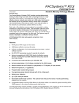
1
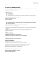
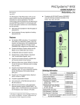
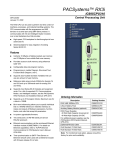
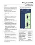
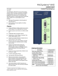
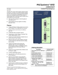
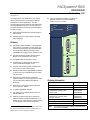
PACSystems* RX3i
IC695CRU320
Redundancy CPU
GFK-2514F
August 2010
*
The PACSystems RX3i Redundancy CPU can be
used to perform real time processing and discrete
automation for various applications. The CPU
communicates with the programmer and HMI devices
via serial SNP Slave protocol. It communicates with
I/O and smart option modules over a dual backplane
bus that provides:
■
High-speed PCI backplane for fast throughput of
advanced I/O.
■
Serial backplane for easy migration of existing
Series 90-30 I/O.
■
Time synchronization to SNTP Time Server on
Ethernet network when used with Ethernet
module version 5.0 or later.
RUN
BATTERY
SYS FLT
CRU320
RESET
STOP
RUN I/O
ENABLE
RUN OUTPUT DISABLE
COM 1
Hot standby (HSB) redundancy. Two redundant
units make up a redundancy system. Each unit
requires one Redundancy CPU (IC695CRU320)
and a redundancy Memory Xchange module
(IC695RMX128) configured as a redundancy link.
■
Contains 64 Mbytes of battery-backed and 64
Mbytes of non-volatile flash user memory.
■
Configurable data and program memory.
■
Programming in Ladder Diagram, Structured
Text, Function Block Diagram, and C.
■
Supports auto-located Symbolic Variables that
can use any amount of user memory.
■
Reference table sizes include 32Kbits for discrete
%I and %Q and up to 32Kwords each for analog
%AI and %AQ.
■
Supports most Series 90-30 modules and
expansion racks. For a list of supported modules,
see the PACSystems RX3i System Manual,
GFK-2314.
■
I/O FORCE
OUTPUTS ENABLED
Features
■
CPU OK
COM1 ACTIVE
COM2 ACTIVE
COM 2
BATT
Ordering Information
Description
Catalog Number
Supports up to 512 program blocks. Maximum
size for a block is 128KB.
RX3i CPU, 1GHz Intel 32 bit processor
IC695CRU320
Auxiliary Battery Module
IC693ACC302
■
In-system upgradeable firmware.
■
Two serial ports: an RS-485 serial port and an
RS-232 serial port.
Standard Power Supplies
120/240VAC, 125VDC, 40W
24VDC, 40W
IC695PSA040
IC695PSD040
■
Ethernet communications via the rack-based
Ethernet Interface module (IC695ETM001). For
details, refer to TCP/IP Ethernet Communications
for PACSystems User’s Manual, GFK-2224.
*
indicates a trademark of GE Intelligent Platforms,
Inc. and/or its affiliates. All other trademarks are
the property of their respective owners.
Multifunctional Power Supplies
120/240 VAC, 125 VDC, 40W
24 VDC, 40 Watt
IC695PSA140
IC695PSD140
[Optional] RS-232 Cable
IC200CBL001
Rx3i Standard 12 Slot Rack
IC695CHS012
Rx3i Standard 16 Slot Rack
IC695CHS016
Note:
For Conformal Coat option, please consult the factory
for price and availability.
2
GFK-2514F
RX3i CRU320
Hot Standby CPU Redundancy Features
For details on the configuration and operation of a Hot Standby CPU redundancy system, refer to the PACSystems
Hot Standby CPU Redundancy User’s Manual, GFK-2308.
■
Survives any one single point of failure
■
Bumpless switching
Synchronized CPUs
One scan switching
Transfer data size up to 2Mbytes; selected in CPU hardware configuration and in variable properties
■
Supports two redundancy communications links
■
Online repair of failed component
■
Online programming
■
Redundancy Memory Xchange Module
Manual toggle switch for role switching, which transitions control from the active unit to the backup unit
Redundancy status LEDs
■
Application-initiated role switching to switch the active unit to backup status
■
Redundancy status bits and message logging
■
Supports single and redundant Ethernet remote I/O LANs through Ethernet Network Interface Unit (ENIU)
modules.
■
Memory error checking and correction (ECC) single bit correcting and multiple bit checking
■
Background diagnostics
HSB Control Strategy
The HSB control strategy has the following characteristics:
■
Active unit does not automatically switch to primary on resynchronization
■
Critical control data plus all redundant outputs must be included in the output data transfer
■
Bumpless switchover from active unit to backup unit
Product Documentation
PACSystems CPU Reference Manual, GFK-2222M or later
TCP/IP Ethernet Communications for PACSystems User’s Manual, GFK-2224
TCP/IP Ethernet Communications for PACSystems Station Manager Manual, GFK-2225
PACSystems Hot Standby CPU Redundancy User’s Manual, GFK-2308D or later
PACSystems Memory Xchange Modules, GFK-2300D or later
PACSystems RX3i System Manual, GFK-2314D or later
PACSystems RX3i Ethernet NIU User’s Manual, GFK-2439
Proficy* Machine Edition Getting Started, GFK-1868
Proficy Logic Developer, GFK-1918
RX3i CPU
3
GFK-2514F
CRU320 Specifications
Note:
For environmental specifications and compliance to standards (for example, FCC or European Union
Directives), refer to the PACSystems RX3i System Manual, GFK-2314.
Battery: Memory retention
Estimated 30 days using an IC693ACC302 Auxiliary Battery Module
at 20ºC.
For details on the operation of the Auxiliary Battery Module, refer to the
datasheet, GFK-2124.
Note: The IC698ACC701 Lithium Battery Pack is not compatible with
the CRU320 and must not be used.
Program storage
Up to 64 Mbytes of battery-backed RAM
64 Mbytes of non-volatile flash user memory
Power requirements
+3.3 VDC: 1.0 Amps nominal
+5 VDC: 1.2 Amps nominal
Operating Temperature
0 to 60°C (32°F to 140°F)
Floating point
Yes
Boolean execution speed, typical
0.047 ms per 1000 Boolean instructions
Time of Day Clock accuracy
Maximum drift of 2 seconds per day
Elapsed Time Clock (internal timing)
accuracy
0.01% maximum
Embedded communications
RS-232, RS-485
Serial Protocols supported
Modbus RTU Slave, SNP Slave, Serial I/O
Backplane
Dual backplane bus support: RX3i PCI and high speed serial bus
PCI compatibility
System designed to be electrically compliant with PCI 2.2 standard
Program blocks
Up to 512 program blocks. Maximum size for a block is 128KB.
Memory
%I and %Q: 32Kbits for discrete
%AI and %AQ: configurable up to 32Kwords
%W: configurable up to the maximum available user RAM
Symbolic: configurable up to 64 Mbytes
Flash memory endurance rating
100,000 write/erase cycles minimum
Memory error checking and
correction (ECC)
Single bit correcting and multiple bit checking.
Switchover Time*
Maximum 1 logic scan, minimum 3.133 msec.
Typical Base Sweep Time (Reference
Data Transfer List Impact)**
3.66 msec: 1K Discrete I/O, 125 Analog I/O and 1K Registers
3.87 msec: 2K Discrete I/O, 250 Analog I/O and 2K Registers
4.30 msec: 4K Discrete I/O, 500 Analog I/O and 4K Registers
5.16 msec: 8K Discrete I/O, 1K Analog I/O and 8K Registers
Maximum amount of data in transfer list Up to 2 Mbytes
Number of redundancy links supported
Up to two IC695RMX128 synchronization links are supported.
*
Switchover time is defined as the time from failure detection until backup CPU is active.
**
Symbolic variable and Reference data can be exchanged between controllers. Up to 2 Mbyte of data is available
for transfer.
Important installation instructions for battery
Do not connect the battery until the CPU is installed in the rack and the rack is powered on. The battery may then be
attached to either of the two terminals in the battery compartment. Once that is done, the CPU may be powered down
and normal battery back up operation will begin. To save battery life, do not connect the battery for the first time until
the CPU is powered up.
RX3i CRU320
4
GFK-2514F
Release History
Catalog Number
Firmware Version
Comments
IC695CRU320-CD
6.02
Provides capability for low battery detection. The new hardware is
EU-ROHS compliant.
For details, see “New Features and Enhancements” on page 6.
IC695CRU320-BC
6.01
Provides for OEM protection in flash-based systems that do not use
a battery. For additional problems resolved, see “Important Product
Information for this Release.”
IC695CRU320-BB
6.00
Adds User Defined Types, Variable Indexed Arrays, Logic Driven
Write to Flash, and Backplane Operations Controller Enhancement
features. See GFK-2514D for details and problems resolved.
IC695CRU320-BA
5.70
Hardware-only upgrade to enhance manufacturability. This change
does not affect product features or functional compatibility.
IC695CRU320-AA
5.70
Initial release
Important Product Information this Release
This release provides the ability to detect low voltage levels in the backup battery for user memory. For details, see
“New Features and Enhancements” on page 6.
Updates
IC695CRU320 can be field upgraded to firmware version 6.02 using the Winloader firmware upgrade utility kit,
82A1559-SW01-001-A3, which can be downloaded from http://www.ge-ip.com/support.
12H
To use the low battery detection feature provided in the 6.02 firmware release, you will need CRU320 hardware
version -Cx or later. Hardware cannot be field upgraded.
For the low battery detection circuit to function properly, an RX3i CPU Lithium Smart Battery (IC695ACC302) must
be used. (Expected availability in 4th quarter, 2010)
CPU Functional Compatibility
Subject
Hardware revision -Cx requires firmware
release 6.02 or newer
Redundancy operation with dissimilar
CPU models is not allowed
Programmer Version Requirements
Description
Firmware revision 6.02 or later must be used for hardware version Cx or higher of the CRU320. This is needed for EMC requirements.
Firmware revision 6.02 is compatible with all earlier versions of
CRU320 hardware.
The CRU320 does not support synchronization with RX7i
redundancy units.
Proficy Machine Edition Logic Developer PLC, version 6.0 or later is
required to use the features added in firmware release 6.00.
Proficy Machine Edition Logic Developer PLC, version 5.9 SP1
SIM5 or later is required to configure a Genius Bus Controller
(IC693BEM331/IC694BEM331) with a CRU320. Only single bus
Genius networks are allowed.
Proficy Machine Edition Logic Developer 5.90 SIM1 or later version
is required to configure and program the CRU320.
RX3i CPU
5
GFK-2514F
Subject
C Toolkit Compatibility
Description
The C Toolkit for PACSystems is distributed with Proficy Machine
Edition Logic Developer. Updates can be downloaded from
http://www.ge-ip.com/support.
The C Toolkit Release 5.50, distributed with Machine Edition Logic
Developer 5.9 or later, is required for use with the CRU320.
Note: C blocks that were built using C Toolkit versions earlier
than 5.00 Build 16C1 must be recompiled using a newer
toolkit version for use with CPU firmware release 5.00 or
higher.
Note: The Series 90 Toolkit (IC641SWP709/719) is not
compatible with PACSystems.
3H4
Rx3i Backplane Hardware Revision
For the CRU320 CPU, one of the following backplane hardware
revisions MUST be used:
IC695CHS012-BAMP
IC695CHS016-BAMP
IC695CHS012CA-BAMP
IC695CHS016CA-BAMP
or
IC695CHS012-CA (or later)
IC695CHS016-CA (or later)
IC695CHS012CA-CA (or later)
IC695CHS016CA-CA (or later)
Power supplies and system modules
As listed in the PACSystems RX3i System Manual, GFK-2314D or
later, with the following exceptions:
Note: The CRU320 does not support the PMM335 PACMotion
Multi-Axis Motion Controller or the BEM331 Genius Bus
Controller modules.
Series 90-30 Expansion Rack
Compatibility
The PACSystems RX3i supports Series 90-30 expansion racks,
both local and remote.
PACSystems RX3i CPUs do not operate in a Series 90-30 Rack.
Note: The RUN LED on the 90-30 Power Supply located in an
expansion rack (both local and remote) will not be illuminated when
the RX3i System is in RUN mode and there are only input modules
in the expansion rack. The RUN LED on the 90-30 Power Supply
located in an expansion rack (both local and remote) will be
illuminated when the RX3i System is in RUN mode and there are
output modules in the expansion rack.
Series 90-30 Main Rack Compatibility
Series 90-30 Main Racks cannot be used in a PACSystems RX3i
system.
Series 90-30 CPUs do not operate in PACSystemsRX3i Racks.
Isolated 24V power
In applications that use the IC69xALG220/221/222, consult
PACSystems RX3i Hardware and Installation Manual, GFK-2314
for details of wiring the 24V power.
COMMREQ to PBM300
In Release 3.0, the behavior of the COMMREQ fault output on a
COMMREQ sent to the PROFIBUS master module IC695PBM300
was changed to be compatible with the Series 90-30 CPU366
PROFIBUS Master. Previously, the fault output is enabled when the
module receives a COMMREQ and it is busy. Now, the busy
condition does not result in the fault output enabled.
RX3i CRU320
6
GFK-2514F
Subject
Description
Recommended IC200ALG240 revision
When a VersaMax* system Genius* Network Interface Unit
(IC200GBI001) operates with a Genius Bus Controller located in a
PACSystems controller, and the VersaMax system contains an
IC200ALG240 Analog Input Module, it is recommended to update
the IC200ALG240 firmware to Revision 1.10 or later. Use firmware
update kit 44A752313-G01, available in Knowledge Base Article
i023269 at http://www.ge-ip.com/support.
5H6
Configuration of IC694MDL754
Always configure 16 bits of module status when using this module.
Configuring 0 bits of module status will result in invalid data in the
module’s ESCP status bits.
New Features and Enhancements
Low Battery Detection
In hardware revisions –Cx or later, the CPU Battery Backup circuit is modified to detect low battery conditions. The
following table lists the battery voltage levels and corresponding user indications.
For the low battery detection circuit to function properly, an RX3i CPU Lithium Smart Battery (IC695ACC302) must
be used. (Expected availability in 4th quarter, 2010)
Battery Voltage
Status of
Battery
BATTERY
LED Status
Battery Voltage >2.5V
Normal Battery
OFF
2V < Battery Voltage <2.5V
Battery Low
BLINK
Battery Voltage <2V
Battery Failed
ON
Compliance
The new hardware is European RoHS compliant.
Restrictions and Open Issues in Release 6.02
Subject
Description
The CPU OK LED blinks and
CPU communications stop after
a power cycle with a battery
connected and starting
from RAM
Very rarely, after experiencing two consecutive rapid power cycles, the CPU may
fail to start properly. When this occurs, the CPU OK LED blinks continuously
(Stop-halt mode) and any communication links to the CPU will be disconnected.
To recover the controller, disconnect the battery and power-cycle.
The Ethernet module fails to
exchange EGD properly during
power cycling
Very rarely, after experiencing multiple rapid power cycles, the CPU may fail to
establish communication with one or more modules in the backplane at power
up. When this occurs, several pairs of "Loss of, or missing option module" and
"Reset of option module" faults will be logged in the controller fault table.
If the module is an ETM, an event 30H is recorded in its station manager event
log.
To recover from this issue, cycle power again.
Switching between Serial & PCI
modules in a slot causes module
to not be recognized.
If a PCI module ( IC695) is configured in a slot and then a Serial module (IC694)
is physically in the location where the PCI module is configured, a module
mismatch fault will be logged. To correct this condition the configuration must
match the module that is physically present in the rack AND the system MUST
be power cycled to correct (simply downloading the new configuration will not
correct this issue).
RX3i CPU
7
GFK-2514F
Subject
Description
Loss of power supplies after
firmware update
A Loss of Power Supplies after firmware update may occur. This does not
happen with all firmware updates and will NOT occur if the system is power
cycled after the firmware upgrade has completed. The faults displayed when this
issue occurs are as follows:
Loss of, or missing option module
Error Code: 36
Group: 4
Action: 3:Fatal
Task Num: 9
Fault Extra Data: 01 58 02 4f 80 08 0a 07 00 00 00 00 00
00 00 00 00 00 00 00 00 00 00 00
Battery installation.
When installing a new battery, if there currently is no battery installed, the battery
must be installed while the CPU has power. Failing to follow this procedure could
result in the CPU not powering up.
If a battery is installed while power is off (and there was no battery previously
installed), and the CPU fails to power up, remove the battery, power cycle the
CPU and then install the battery.
Hot swapping some analog
modules slowly results in
modules not being recognized.
Occasionally during a hot insertion (hot swap) of RX3i Non-Isolated Analog Input
Modules, input channels may take up to 2 seconds to reflect actual input values
after the module OK bit is enabled in the module status word. This has only been
seen when the hot insertion has been done slowly (i.e. approximately 1.5
seconds to insert the module).
Ethernet disconnect during
Word-for Word change.
If the Ethernet connection is broken during a word-for-word change, the
programmer may not allow a subsequent word-for-word change after
reconnecting due to the fact that it thinks another programmer is currently
attached. If this occurs, you should go offline and then back online again.
Simultaneous Clears, Loads and
Stores not supported.
PACSystems CPUs do not support multiple programmers changing CPU
contents at the same time. The programming software may generate an error
during the operation. Simultaneous loads from a single CPU are allowed.
Hardware configuration Not
Equal after changing target
name.
If you store a hardware configuration to flash that sets Logic/Config Power up
Source to Always Flash or Conditional Flash and then change the name of the
target in the programming software, the hardware configuration will go Not Equal
and will not verify as equal.
Controller and IO Fault Tables
may need to be cleared twice to
clear faulted state.
Both Controller and IO fault tables may need to be cleared to take the CPU out
of Stop/Fault mode. If one of the tables contains a recurring fault, the order in
which the tables are cleared may be significant. If the CPU is still in Stop/Fault
mode after both tables are cleared, try clearing the fault tables again.
Setting Force On/Off by storing
initial value.
Once a force on or force off has been stored to the controller, you cannot switch
from force on to force off or vice-versa by downloading initial values. To turn the
force on or off, download the project.
Number of active programs
returned as zero.
The SNP request Return Controller Type and ID currently returns the number of
active programs as zero.
Serial I/O fails at 115K during
heavy interrupt load.
Rare data corruption errors have been seen on serial communications when
running at 115K under heavy interrupt load on the controller. Under heavy load
applications, users should restrict serial communications to 57K or lower.
SNP ID not always provided.
Unlike the Series 90-30, the RX3i CPU’s SNP ID does not appear in the Machine
Edition programmer Show Status display. Service Request 11 will always return
zeros.
Second programmer can change
logic while in Test & Edit mode.
While currently active in a Test and Edit session using Machine Edition on one
PC, Machine Edition running on another PC is not prevented from storing new
logic to the controller.
Must have logic if powering up
from flash.
If the application will configure the CPU to retrieve the contents of flash memory
at power-up, be sure to include logic along with hardware configuration when
saving to flash memory.
RX3i CRU320
8
GFK-2514F
Subject
Description
CPU may not detect low-battery
condition.
A battery with very low capacity may still have a terminal voltage high enough to
report that it is a good battery. In this case, when the battery starts supplying the
memory power (battery backup), the battery voltage quickly drops to
unacceptable levels, with little warning to the user before failure.
To insure against data loss, users should replace batteries in accordance with
the guidelines provided in the PACSystems CPU Reference Manual, GFK-2222.
Additionally, users could save logic and hardware configuration to flash.
Two Loss of Module faults for
Universal Analog module.
Occasionally, the hot removal of the Universal Analog Input Module
(IC695ALG600) results in two Loss of I/O Module faults instead of one.
Power up of Series 90-30 HSC
module may take as long as 20
seconds.
As power is applied to a 90-30 High-Speed Counter, the Module Ready bit in the
status bits returned each sweep from the module may not be set for as long as
20 seconds after the first controller sweep, even though there is no Loss of
Module indication. I/O data exchanged with the module is not meaningful until
this bit is set by the module. See pages 4-3 to 4-5 of the Series 90-30 High
Speed Counter User’s Manual, GFK-0293C.
Informational fault at power up.
Intermittently during power-up, an Informational non-critical CPU software fault
may be generated with fault extra data of 01 91 01 D6. This fault will have no
effect on the normal operation of the controller. But, if the hardware watchdog
timer expires after this fault and before power has been cycled again, then the
outputs of I/O modules may hold their last state, rather than defaulting to zero.
Extended memory types for IO
triggers.
%R, %W and %M cannot be used as IO triggers.
Possible Machine Edition
inability to connect.
Infrequently, an attempt to connect a programmer to a controller via Ethernet will
be unsuccessful. The normal connection retry dialog will not be displayed.
Rebooting the computer that is running the programmer will resolve the
behavior.
SNP Update Datagram message.
If an Update Datagram message requests 6 or less bits or bytes of data, the
controller will return a Completion Ack message without Text Buffer. The
protocol specifies that the returned data will be in the Completion Ack message,
but it may not be.
Configuration of third-party
modules.
Do not specify a length of 0 in the configuration of a third-party module. The
module will not work properly in the system.
Power supply status after CPU
firmware update.
The controller will report a Loss of or Missing Option Module fault for the
IC695PSD140 RX3i power supply following an update of CPU firmware. Also,
the slot will appear empty in the programmer’s online status detail view. The
power supply continues to operate normally. Power cycle to restore normal
status reporting.
Power supply status after power
cycling.
Rarely, turning a power supply on or off may not result in an Add or Loss fault.
Also, the slot will appear empty in the programmer’s online status detail view.
The power supply continues to operate normally. Power cycle to restore normal
status reporting.
Don’t use multiple targets.
In a system in which the hardware configuration is stored from one target and
logic is stored from a different target, powering-up from flash will not work. The
observed behavior is that, following a power up from flash, Machine Edition
reports hardware configuration and logic Not Equal.
Missing Loss of Terminal Block
fault.
The IC695ALG600/608/616 analog input modules do not produce a Loss of
Terminal Block fault when hardware configuration is stored or the module is hotinserted, and the terminal block is not locked into place.
RX3i CPU
9
GFK-2514F
Subject
Description
Sequence Store failure.
When downloading projects with very large hardware configurations or which
use large amounts of user memory, it is possible to encounter a controller
Sequence Store Failure error when writing the configuration to flash. To work
around this error, either, either or both of the following actions may be helpful:
1. Perform an explicit clear of flash prior to performing the write.
2. Increase the operation timeout used by Machine Edition prior to performing
the write. This is done by expanding the Additional Configuration in the
Inspector window for the target controller, and adjusting the Request
Timeout. The timeout may need to be increased to as much as
60,000 msec, depending on the amount of memory used and the condition
of the flash memory.
IC694MDL754: Must configure
module status bits.
Always configure 16 bits of module status when using this module. Configuring 0
bits of module status will result in invalid data in the module’s ESCP status bits.
IC695ALG600 Lead Resistance
Compensation setting.
A configuration store operation will fail if a channel is configured for 3-wire RTD
and Lead Resistance Compensation is set to Disabled. A Loss of Module fault
will be logged in the I/O Fault table at the end of the store operation.
To recover the lost module, the configuration must be changed to enable Lead
Resistance Compensation and module must be power cycled.
C Toolkit PlcMemCopy
documentation incorrect.
This routine does allow the destination and source pointers to be outside of
reference memory. If the destination points to discrete reference memory,
overrides and transitions will be honored. Note that the header for PlcMemCopy
has been updated in Release 3.50 of the C toolkit.
WinLoader may stop operating.
On computers running Windows 2000 and using some versions of Symantec
Antivirus protection, WinLoader will lock up if used in advanced mode. Recovery
requires cycling the computer's power.
Logic and HWC not equal after
power cycle.
If the Hardware Configuration from Target 1, with Logic/Configuration Power-up
Source and Data Source both set to Always from Flash, is stored in Flash, then
Logic and Hardware Config from Target 2, with Logic/Configuration Power-up
Source both set to Always from RAM, are stored to RAM and there is a good
battery, then when power is cycled the programmer may show that Logic and
Hardware Config are not equal.
The remedy is to clear Flash and re-store the Logic and Hardware Config from
Target 2.
WinLoader does not detect PC
COM port in use when upgrading
PACSystems CPU.
WinLoader does not detect if a PC's COM port is in use when attempting to
connect to a PACSystems CPU to perform a firmware upgrade. If the port is
already in use it displays the status "trying to connect" followed by "waiting for
target." To proceed with the upgrade, press the "abort" button and disconnect
the other application that is using the COM port.
CPU320, CRU320 user
application and values cleared
after power cycle
Under rare circumstances during multiple rapid power cycles the
CPU320/CRU320 will power up with the user application and data in RAM
cleared. There will be a “Corrupted user memory” fault in the controller fault table
(Group 130, Error code 1). This will not occur if the user application and data are
loaded from flash on power-up (“Always Flash” or “Conditional Flash”).
WinLoader does not display
error when it can't connect
serially with PACS CPU.
WinLoader does not display an error message if it cannot connect to the PACS
CPU when attempting to connect to a PACSystems CPU to perform a firmware
upgrade. This occurs if the cable is physically not connected to the CPU or if the
CPU's serial port is not configured for the same baud as WinLoader. In this case
Winloader displays the status "trying to connect" followed by "waiting for target."
To proceed with the upgrade, press the "abort" button and correct the cable or
baud rate setting.
RX3i CRU320
10
GFK-2514F
Operational Notes
Subject
Description
Monitoring RMX links
ALL applications should monitor the fault locating references corresponding
to the RMX modules at power up and during run time to validate the RMX
links are operating. The fault locating reference name format is
#SLOT_00XX where XX is the slot number of the RMX module.
Block name now provided in
User Application faults
In firmware versions earlier than 6.01, the fault entry for a non-fatal
application fault (for example, reference-out-of-range) provided numeric
information to identify the logic block causing the error. However, the user
did not have a way to correlate the numeric information with the name of the
block. Firmware versions 6.01 and later include the first 12 characters of the
block name in the fault entry.
RUN LED is not illuminated on
the Series 90-30 power supply
for an RX3i remote/expansion
rack with input modules only
When a remote or expansion baseplate is used with the RX3i, the RUN LED
on the Series 90-30 power supply for that baseplate is illuminated when the
system is in Run mode only if the rack contains at least one output module.
If the rack contains input modules only, the RUN LED is not illuminated.
This is due to the way input modules are managed in the PACSystems
design and does not indicate an error.
In Release 5.00 or later, if an attempt is made to download a C block
containing undefined symbols, the download will fail. Machine Edition will
display the following message in the Feedback Zone: Error 8097: Controller
Error – Controller aborted the request [0x05][0xFF]
Prior to Release 5.00, C blocks containing undefined symbols could be
successfully downloaded, but if they were executed the CPU would
transition to Stop/Halt mode.
For details, see “C Toolkit Compatibility” on page 5.
Undefined symbols in C Blocks.
9H
Length of serial I/O buffer
(Release 5.0 or later) The "Set Up Input Buffer Function" always allocates a
buffer containing 2049 bytes. This is one byte more than previous
PACSystems releases.
Changing IP address of Ethernet
interface while connected.
Downloading a hardware configuration with a new IP address to the RX3i
while connected via Ethernet will succeed, then immediately disconnect
because the RX3i is now using a different IP address than the Programmer.
You must enter a new IP address in the Target Properties in the Machine
Edition Inspector window before reconnecting.
Duplicate station address for
Modbus will conflict with other
nodes.
The default serial protocol for the RX3i is Modbus RTU. The default Station
Address is 1. If the RX3i is added to a multi-drop network, care must be
taken that the RX3i is configured with a unique Station Address. Nodes with
duplicate Station Addresses on the same network will not work correctly.
Timer operation.
Care should be taken when timers (ONDTR, TMR, and OFDTR) are used in
program blocks that are NOT called every sweep. The timers accumulate
time across calls to the sub-block unless they are reset. This means that
they function like timers operating in a program with a much slower sweep
than the timers in the main program block. For program blocks that are
inactive for large periods of time, the timers should be programmed in such
a manner as to account for this catch up feature.
Related to this are timers that are skipped because of the use of the JUMP
instruction. Timers that are skipped will NOT catch up and will therefore not
accumulate time in the same manner as if they were executed every sweep.
Constant Sweep
Constant Sweep time, when used, should be set at least 10 milliseconds
greater than the normal sweep time to avoid any over-sweep conditions
when monitoring or performing on-line changes with the programmer.
Window completion faults will occur if the constant sweep setting is not high
enough.
RX3i CPU
11
GFK-2514F
Subject
Description
Large number of COMMREQs
sent to module in one sweep
causes faults.
A large number of COMMREQs (typically greater than 8) sent to a given
board in the same sweep may cause Module Software faults to be logged in
the RX3i fault table. The fault group is MOD_OTHR_SOFTWR (16t, 10h)
and the error code is COMMREQ_MB_FULL_START (2). When this occurs,
the “FT” output of the function block will also be set. To prevent this
situation, COMMREQs issued to a given board should be spread across
multiple sweeps so that only a limited number (typically 8 or less) of
COMMREQs are sent to a given board in each sweep. In addition, the FT
output parameter should be checked for errors. If the FT output is set
(meaning an error has been detected), the COMM_REQ could be re-issued
by the application logic.
C Block standard math functions
do not set errno.
In C Blocks, standard math functions (e.g. sqrt, pow, asin, acos) do not set
errno to the correct value and do not return the correct value if an invalid
input is provided.
Upgrading firmware.
The process of upgrading the CPU firmware with the WinLoader utility may
fail when multiple IO modules are in the main rack, due to the time it takes
to power cycle the rack system. If the upgrade process fails, move the CPU
to a rack without IO modules and restart the upgrade process.
Winloader initial connect baud rate is fixed at 19200 baud. Note that the
firmware download will occur at 115.2K baud by default.
Note that if you have hyperterm open on a port, and then try to use
Winloader on the same port, Winloader will often say “Waiting for Target”
until the hyperterm session is closed.
Hot swap.
Hot Swap of power supplies or CPUs is not supported.
Serial port configuration
COMMREQs.
With the following combination of circumstances, it is possible to render
serial communications with the CPU impossible:
User configuration disables the Run/Stop switch
User configures the power up mode to Run or Last
Logic is downloaded to FLASH and user configures CPU to load
from FLASH on power up
User application issues COMMREQs that set the protocol on both
of the serial ports to something that does not permit
communications to the Machine Edition programmer.
Incorrect COMMREQ status for
invalid program name.
The program name for PACSystems is always "LDPROG1". When another
program name is used in a COMM_REQ accessing %L memory, an Invalid
Block Name (05D5) error is generated.
FANUC I/O Master and Slave
operation.
Scan sets on the master do not work properly for the first operation of the
scan set after entering RUN mode. They do work properly for subsequent
scans.
After downloading a new hardware configuration and logic, a power cycle
may be required to resume FANUC I/O operation.
Use controllers of similar performance in FANUC I/O networks. If a master
or slave is located in an RX3i system, the other controllers should be RX3i
or Series 90-30 CPU374.
Repeated power up/down cycles of an expansion rack containing FANUC
I/O slaves may result in failure of the slaves’ operation, with the RDY LED
off.
Lost count at power up for Serial
IO Processor.
The serial IO Processor (IC693APU305) will lose the first count after every
power up or every time the module receives a configuration.
RX3i CRU320
12
GFK-2514F
Subject
Description
COMMREQ status words
declared in bit memory types
must be byte-aligned.
In previous releases, the CPU allowed configuration of COMMREQ Status
Words in bit memory types on a non-byte-aligned boundary. Even though
the given reference was not byte-aligned, the firmware would adjust it the
next-lowest byte boundary before updating status bits, overwriting the bits
between the alignment boundary and specified location. To ensure that the
application operates as expected, release 3.50 requires configuration of
COMMREQ Status Words in bit memory types to be byte-aligned. For
example if the user specified status bit location of %I3, the CPU aligns the
status bit location at %I1. Release 3.50 firmware requires the user to
specify the appropriate aligned address (%I1) to ensure that the utilized
location is appropriate for their application. Note that the actual reference
location utilized is not changed, but now is explicitly stated for the user.
Suspend IO Function Block does
not Suspend EGD
In a Series 90-70 the SUSPEND_IO function block suspends EGD in
addition to IO Scan. In PACSystems controllers the SUSPEND IO only
suspends IO Scan.
STOP and RUN mode transition
priority
The PACSystems CPU receives requests to change between stop and run
mode from many different sources. These include (but are not limited to)
Proficy Machine Edition, HMIs, the user application, and the RUN/STOP
switch. Since there are many potential sources for a mode change request,
it is possible to receive a new mode change request while another is
already in progress. When this occurs, the CPU evaluates the priority of the
new mode change request with the mode change that is in progress. If the
new mode change request has an equal or higher priority than the one
already in progress, the CPU transitions to the new mode instead of the
one in progress. If, however, the new mode change request has a lower
priority than the one in progress, the new mode request is discarded and
the CPU completes the mode change that is in progress. The sweep mode
priorities are (listed from highest to lowest priority): STOP HALT, STOP
FAULT, STOP, and RUN. (Note: The IO ENABLED/DISABLED state is not
part of the mode priority evaluation.) For example, a CPU is in RUN IO
ENABLED mode and a Service Request 13 function block is executed to
place the CPU into STOP IO DISABLED mode. Before the transition to
STOP IO DISABLED is completed, the RUN/STOP switch is changed from
RUN IO ENABLED to RUN IO DISABLED. In this case, the CPU ignores
the new request from the RUN/STOP switch to go to RUN IO DISABLED
mode because it is already processing a request to go to STOP IO
DISABLED mode and STOP mode has a higher priority than RUN mode.
Installation in Hazardous Locations
The following information is for products bearing the UL marking for Hazardous Locations:
WARNING - EXPLOSION HAZARD - SUBSTITUTION OF COMPONENTS MAY IMPAIR SUITABILITY FOR
CLASS I, DIVISION 2;
WARNING - EXPLOSION HAZARD - WHEN IN HAZARDOUS LOCATIONS, TURN OFF POWER BEFORE
REPLACING OR WIRING MODULES; AND
WARNING - EXPLOSION HAZARD - DO NOT CONNECT OR DISCONNECT EQUIPMENT UNLESS POWER
HAS BEEN SWITCHED OFF OR THE AREA IS KNOWN TO BE NONHAZARDOUS.
EQUIPMENT LABELED WITH REFERENCE TO CLASS I, GROUPS A, B, C & D, DIV. 2 HAZARDOUS
LOCATIONS IS SUITABLE FOR USE IN CLASS I, DIVISION 2, GROUPS A, B, C, D OR NON-HAZARDOUS
LOCATIONS ONLY
The tightening torque range for the control terminals is 9.6–11.5 in. lb. Use only wire rated for 90°C. Be sure to
observe any additional ratings that are provided with the modules.