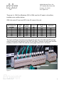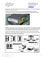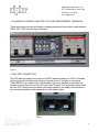
1
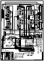
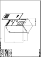
Indoor Fire Protection UPS System AFP 10 Series AIP900-0012-B0-001 Rev. , 2/2011 Alpha Industrial Power, member of the Alpha Group Suwanee, GA, USA. Telephone: 1 800 996 6104 Fax: 678 584 9259 Alpha Technologies reserves the right to make changes to the products and information contained in this document without notice. Copyright 2011 Alpha Technologies Inc. All Rights Reserved. Visit www.alpha.com Alpha Industrial Power Indoor Fire Protection UPS System AFP 10 Series Rev. , 2/2011 Table of Contents 1. 2. Safety Instructions 3 4. Page 48 Introduction Page 9 1014 Component Manual Reference Information Page 15 5. UPS system drawings Pages 16-18 6. Alpha Industrial Power Product Warranty Page 20 7. Alpha Industrial Power Factory Service Information Page 21 Alpha Industrial Power, member of the Alpha Group Suwanee, GA, USA. Telephone: 1 800 996 6104 Fax: 678 584 9259 Alpha Technologies reserves the right to make changes to the products and information contained in this document without notice. Copyright 2011 Alpha Technologies Inc. All Rights Reserved. Visit www.alpha.com Alpha Industrial Power, Inc. 1075 Satellite Blvd. Suite 400 Suwanee, GA 30024 www.alpha.com TECHNICAL MANUAL: AFP 10 SERIES UPS 1.0 SCOPE 1.1 System This manual describes a continuous duty, single phase, on-line, solid state uninterruptible power supply system, hereafter referred to as the FP 10 series modular UPS. 2.0 SYSTEM DESCRIPTION 2.1 Applicable Standards The FP UPS is compliant with the current revisions of the following standards: • ANSI C62.41 (IEEE 587) – Guide on Surge Voltages in AC Power Circuits (up to 600V) • UL 1481 – Standard for Safety Power Supplies for Fire-Protective Signaling Systems • National Electrical Code (NFPA-70) • NEMA PE 1-2003 – Uninterruptible Power Systems (UPS) – Specification and Performance Verification • OSHA 2.2 Components The FP 10 UPS consists of the following components: A. Cordex™ switched mode charger/rectifier B. Cordex™ System Controller (CXC), Software Version 2.0 C. Pulse-Width Modulated (PWM) modular Inverter with built in modular static switch D. Manual Make- Before-Break (MBB) bypass switch E. Input Circuit Breaker & Output Breaker 4 Alpha Industrial Power, Inc. 1075 Satellite Blvd. Suite 400 Suwanee, GA 30024 www.alpha.com 2.3 AFP 10 Series UPS Model Number Explanation AFP10 - XXX - X I 1 Series System Input/Output Voltage (1=120VAC) Indoor Power Rating (050=5kVA,075=7.5kVA,100=10kVA) Quantity of Rectifiers (1-7) Example: AFP 10 Series Modular UPS, 5 KVA Power Rating, Quantity of Rectifier Modules = 5, Indoor, 120VAC System Input/Output Voltage AFP10 - 050 - 5 I 1 Series System Input/Output Voltage (1=120VAC) Indoor Power Rating (050=5kVA,075=7.5kVA,100=10kVA) Quantity of Rectifiers (1-7) UPS Input - AFP10-050-XI1, AFP10-075-XI1, AFP10-100-XI1 120 VAC, 1 Phase, 50/60 Hz, 12A max per rectifier module, 20.8 max per inverter module; Supervised UPS Output AFP10-050-XI1 - 120 VAC regulated, 1 Phase, 50/60 Hz, 5 kVA, 0.75pf AFP10-075-XI1 - 120 VAC regulated, 1 Phase, 50/60 Hz, 7.5 kVA, 0.75pf AFP10-100-XI1 - 120 VAC regulated, 1 Phase, 50/60 Hz, 10 kVA, 0.75pf 5 Alpha Industrial Power, Inc. 1075 Satellite Blvd. Suite 400 Suwanee, GA 30024 www.alpha.com 2.4 System Operation The FP 10 UPS operates as an on-line, following modes 10 fully automatic system in the : A. NORMAL - Incoming AC power is boosted using a switching circuit, into DC power . The ower . . B. EMERGENCY - Upon failure of commercial AC power, the UPS derives power from the battery bank and continues to feed the load with clean, regulated AC power. There is no interruption to the critical load upon failure or restoration of commercial AC power. 6 Alpha Industrial Power, Inc. 1075SatelliteBlvd.Suite400 Suwanee, GA 30024 www.alpha.com C. RECHARGE - Upon restoration of the commercial AC source, the switched mode rectifier/charger powers the inverter while simultaneously recharging the battery bank. The AFP 10 UPS has the following recharge process: a) a constant level of current is used to recharge the batteries (the process utilizes a current-limit function to prevent overcharging batteries, thus extending the life of the batteries). b) as the batteries reach the normal charge level, a constant-voltage control begins which causes the battery recharge current to gradually decrease. c) under normal operation, the UPS battery bank "floats" at the 2.25-2.27 volts per cell DC level to stay fully charged and ready for the next discharge. D. BYPASS MODE - Upon detection of an internal inverter fault, the UPS automatically switches from inverter power to an AC input source via the built-in static switch. Transfer occurs within 1 millisecond, causing no interruption to the critical load. Return from the bypass mode is an automatic function, without interruption to the critical load. Transfer to Bypass may also be performed as a manual operation via the UPS manual bypass switch located in the front panel. E. POWER CONDITIONING MODE - Should the batteries be removed from the UPS, the UPS continues to function and provides protection against spikes, common/normal mode noise, load steps and frequency shifts (without battery back-up capability). 3.0 SYSTEM SPECIFICATIONS A. UPS Input 1) Input Voltage: 120VAC (Supervised) 2) Input Voltage Requirement: 1 Phase, 2 Wire + Ground 3) Input Current: 12AMax @ 90-135VAC per each rectifier module. 20.8A @ 120VAC Nominal per each inverter module. 4) Rated Frequency: 50/60 Hz 5) Nominal Battery Voltage: 48VDC 6) Maximum Charge Current: 220A 7) Maximum Battery Capacity: 1600Ah (Supervised) 7 Alpha Industrial Power, Inc. 1075 Satellite Blvd. Suite 400 Suwanee, GA 30024 www.alpha.com B. UPS Output 1) 2) 3) 4) 5) 6) Rated Voltage: 120VAC Output Voltage Requirements: 1 Phase, 2 Wire + Ground Output Capacity: 5/7.5/10 kVA Rated Load Power Factor : 0.75 lagging Frequency: 50-60Hz. Programmable Relays: 60VDC, 1A, Resistive (Supplemental use) C. Environmental 1) Operating Temperature: UPS: 32° to 120°F (0° to 49°C) Battery: 68° to 77°F (20° to 25°C) 2) Storage Temperature: UPS: -4° to 1 40 °F (- 2 0° to 6 0°C) Battery: prolonged storage above 104°F (40°C) causes rapid battery degradation 3) Relative Humidity: 90% (non-condensing) 8 IMPORTANT SAFETY INSTRUCTIONS SAVE THESE INSTRUCTIONS 1. Please read this manual prior to use to become familiar with the product’s numerous features and operating procedures. To obtain a maximum degree of safety, follow the sequences as outlined. 2. This manual provides warnings and special notes for the user: a. Points that are vital to the proper operation of the product or the safety of the operator are indicated by the heading: WARNING or SECURITY & SAFETY. The symbols listed above also alert the user to warnings. b. A notation that is in Bold or Italic typeface covers points that are important to the performance or ease of use of the product. 3. Before using the product, read all instructions and cautionary markings on the product and any equipment connected to the product. 4. Only qualified personnel should install, operate, and service the product and its components. 5. Observe all applicable national and local electrical codes when installing the product. 6. Always assume electrical connections or conductors are live. 7. Do not expose the product to rain or snow; install only in a clean, dry environment. 8. CAUTION – Unless otherwise noted, use of an attachment not recommended or sold by the product manufacturer may result in a risk of fire, electric shock, or injury to persons. 9. CAUTION – Do not operate the product if it has received a sharp blow, it has been dropped, or otherwise damaged in any way – return it to a qualified service center for repair. 10. CAUTION – Do not disassemble the product – call our qualified service centers for servicing. Incorrect reassembling may result in a risk of electrical shock or fire. 11. CAUTION – The TSI inverter rack is not supplied with internal disconnect devices and is a dual input power supply system. For proper installation, system access, and safety instructions (including proper grounding), please refer to Chapter 3 of the TSI Inverter Installation manual. 9 Alpha Industrial Power, Inc. 1075 Satellite Blvd. Suite 400 Suwanee, GA 30024 www.alpha.com INSTALLATION 1.1 RECEIVING THE AFP 10 UPS When the UPS is received, please attend immediately to its unpacking, carefully removing all shipping material and packaging. Carry out an accurate visual inspection to ensure that the equipment has not been damaged during transport. Make sure to save all packaging and shipping materials until it has been determined that no shipping damage has occurred. IMPORTANT If any damage is discovered upon delivery of the UPS, make sure to notate damages on all copies of the delivering carrier’s delivery receipt prior to signature. If damage is discovered after the delivery, immediately notify the delivering carrier and request an inspection. The manufacturer assumes no liability for damages during transportation and handling. 1.2 STORING THE AFP 10 UPS Should the UPS need to be stored prior to installation, it should be stored in its original shipping packaging, in an upright position as indicated on the packaging. The UPS should only be stored in a temperature-controlled, dry, and dust-free sheltered room. 1.3 HANDLING AND LOCATING OF THE AFP 10 UPS For handling of the UPS prior to installation, it is recommended that the UPS remain attached to its shipping pallet, to reduce risk of over-turning. Immediately prior to the UPS installation, the UPS should be removed from the shipping pallet. The UPS should then be placed into the final installation position by use of a forklift. The UPS must be installed in a clean, dust-free, dry room. If the UPS includes an internal VRLA battery bank, the room must be properly ventilated in order to reduce heat and provide for optimum system performance. It is strongly recommended that the UPS be installed in a temperature-controlled room in order to maximize the life of the battery bank. 1.4 AC INPUT/OUTPUT CONNECTION The electrical connections are a part of the installation that must be provided by a qualified, trained UPS installer, and must meet all standards per local electrical code. The manufacturer of the AFP 10 UPS is not responsible for the electrical connection. The following information is provided to serve only as a guideline for the qualified installer. However, the AFP 10 UPS manufacturer recommends that the installer use correct cable sizes and circuit breakers as shown below: 10 Alpha Industrial Power, Inc. 1075 Satellite Blvd. Suite 400 Suwanee, GA 30024 www.alpha.com There are 4 x 32A Circuit Breakers (CB1 to CB4) used for AC inputs to all rectifiers, installed on two rectifier shelves. CB5 is the main AC input and CB7 is the AC output of the unit. NUMBER OF RECTIFIERS ON AC FEED 2 2 2 2 N/A N/A AC INPUT CBs AC INPUT CB SIZE CB1 CB2 CB3 CB4 CB5 N/A 32A 32A 32A 32A 100A N/A AC OUTPUT CBs N/A N/A N/A N/A N/A CB7 AC OUTPUT CB SIZE WIRE SIZE N/A N/A N/A N/A N/A 100A #10 #10 #10 #10 #2 #2 The Input and Output terminals are located at the right side of the AFP 10 UPS and can easily be accessed from the front of the UPS (see figure 1 below). All GND wires must be properly connected to GND TBs with the same gauge sizes of AC L & N wires. Figure 1 11 Alpha Industrial Power, Inc. 1075 Satellite Blvd. Suite 400 Suwanee, GA 30024 www.alpha.com Please refer to the AFP 10 UPS electrical drawing (see Section 5, UPS System Drawings) for inputs and output connection. For alarm relay contacts for remote monitoring, access the alarm contact terminals by removing the communication terminal cover (see figure 2 below). See page 8 for ratings. Figure 2 NOTE: All intermediate communication devices (router, SCADA, etc.) required for remote monitoring communications must be located within the same room in which the AFP 10 UPS unit is installed. supplemental . All alarm free voltage relay contacts are programmable via the Cordex controller software. Please refer to the Cordex controller software section (see Section 3B) and alarm contact identifications as illustrated in the drawing below: REVISIONS LTR NO C NC NO K3 C NC NO K1 C NC K5 1 2 3 P3 D5 D6 13 14 15 16 17 18 19 20 21 22 23 24 1 NO 2 C K6 3 NC 4 NO 5 C K4 6 NC 7 NO 8 C K2 9 NC 10 I1 11 + 12 D6 V1 GP2 GP4 - 26 + 27 - 28 + 29 - 30 + 31 - 32 T1 + 33 34 D2 35 36 D4 37 38 39 + 40 41 + 42 43 + 44 45 + 46 47 48 49 REV BY DESCRIPTION DATE APPD I2 GP1 GP3 T2 D1 D3 DB15 PIN OUT 1. K6 - NO 2. K6 - NC 3. K5 - COM 4. K4 - NO 5. K4 - NC 6. K3 - COM 7. K2 - NO 8. K2 - NC 9. K6 - COM 10. K5 - NO 11. K5 - NC 12. K4 - COM 13. K3 - NO 14. K3 - NC 15. K2 - COM 1 8 1 5 9 15 6 9 13 1 25 14 P3 JUMPER SETTINGS (FOR LVD CONTROL INHIBIT FUNCTION) SHORT PINS 1 AND 2 IF LVD IS CONTROLLED ON K1-NC CONTACTS TO MAINTAIN OPERATION. DB9 PIN OUT FRONT VIEW SECURE SIGNAL WIRES TO SIDE FLANGES SHORT PINS 2 AND 3 IF LVD IS CONTROLLED ON K1-NO CONTACTS TO MAINTAIN OPERATION 1. 2. 3. 4. 5. 6. 7. 8. 9. I1K1- NO K1- NC D6 D5 I1+ K1 - COM D6 D5 DB25 PIN OUT 14. I2 + 1. I2 15. V1 + 2. V1 16. GP1 + 3. GP1 17. GP2 + 4. GP2 18. GP3 + 5. GP3 19. GP4 + 6. GP4 20. T2 + 7. T2 21. T1 + 8. T1 22. D1 9. D1 23. D2 10. D2 24. D3 11. D3 25. D4 12. D4 13. NOT CONNECTED TOP VIEW - WITH COVER REMOVED THESE DESIGNS AND SPECIFICATIONS ARE THE PROPERTY OF ALPHA TECHNOLOGIES AND SHALL NOT BE COPIED OR USED FOR MANUFACTURING WITHOUT ITS WRITTEN CONSENT. 15 PIN CABLE P/N 877-498-10 REMOVE SCREW AND SLIDE COVER OFF ISOMETRIC VIEWS 25 PIN CABLE P/N 877-499-10 9 PIN CABLE P/N 877-497-10 DESIGN J.K. 2006/04 DRAWN J.U. JK 2006/07 2006/07 GS 2006/07 CHECKED APPROVED TOLERANCES X.X X.XX X.XXX 0.04" 0.02" 0.01" [X] [X.X] [X.XX] 1mm 0.5mm 0.25mm MATERIAL SEE B.O.M. 036-200-20 FINISH PER P.O. and Doc. 070-024-83 SCALE N.T.S. TITLE CUST CONN, CTRLR I/O, TERM BLOCK, 1.8kW SHELF + CXCM2 ISSUE DATE SIZE TYPE D W G N O . B D2 SHEET 1 OF 1 036-200-08 REV A 12 Alpha Industrial Power, Inc. 1075 Satellite Blvd. Suite 400 Suwanee, GA 30024 www.alpha.com 1.5 CHARGING CURRENT & BATTERY VOLTAGE MEASUREMENT TERMINALS There are charging current and battery voltage measurement terminals located between CB5 & CB7 of the unit (see figure 3 below). Figure 3 1.6 BATTERY CONNECTION The UPS back-up battery bank may be a 48VDC external battery set (VRLA or flooded battery type) with a battery back-up time of greater than 15 minutes, or an internal 100AH/48VDC max. battery bank (VRLA battery type only) installed on a battery tray located on the bottom floor of the UPS (see figure 4 below). For any battery banks used with the UPS, please follow the battery manual provided by the battery manufacturer to insure proper installation and maintenance of the battery bank. Figure 4 13 Alpha Industrial Power, Inc. 1075 Satellite Blvd. Suite 400 Suwanee, GA 30024 www.alpha.com Note: The stand-by battery maximum operating back-up time (1600AH VRLA battery) is 10.5 hours, with a battery re-charge time within 48 hours. This figure is based on the AFP10 UPS with a full load of 7 Cordex rectifier modules. Please refer to the battery manufacturer’s manual for detailed battery specifications. Please refer to the AFP10 UPS electrical drawing (see Section 5) for battery connection to the UPS. Note: Only a qualified battery installer should be used for installation of the battery bank, and should use only correctly sized battery connecting cables, as defined by the load current requested for the AFP 10 UPS unit. To obtain the battery life indicated by the battery manufacturer, the operating temperature must remain between 0 and 25 °C. However, although the battery can operate in temperatures up to 40 °C, a significant reduction of the battery life will occur. Further, to avoid the formation of potentially explosive gasses, suitable ventilation must be provided at the location of the battery, per NFPA 70 PE requirements. Warning: CORRECT BATTERY POLARITY CONNECTIONS MUST BE FOLLOWED TO AVOID SERIOUS DAMAGE TO THE AFP 10 UPS UNIT. Note: Limited to same room battery bank installations. Non-power limited wiring required. Battery connection must be in an area of limited access. Must be approved by AHJ. 14 Alpha Industrial Power, Inc. 1075 Satellite Blvd. Suite 400 Suwanee, GA 30024 www.alpha.com Component Manual Reference Information For detailed information (specifications, features, configuration, etc.) concerning the Cordex™ 48VDC Modular Switched Mode Rectifier System, please refer to Manual 030-809-B2 Rev. B, “CXRF 48-1.8kW”, 2008. For detailed information concerning the Cordex ™ Controller Software, Version 2.0, please refer to Manual 034-136-B2 Rev. B, “Cordex Controller Software Version 2.0”, 2009. For detailed information (specifications, features, configuration, etc.) concerning the Bravo TSI 120VAC Inverter System, please refer to Manual “TSI BRAVO 120VAC User Manual V3.3”, 3/2/2009. 15 Fire Protection UPS System Technical Drawings Alpha Industrial Power, member of the Alpha Group Visit www.alpha.com Suwanee, GA, USA. Telephone: 1 800 996 6104 Fax: 678 584 9259 Alpha Technologies reserves the right to make changes to the products and information contained in this document without notice. Copyright 2011 Alpha Technologies Inc. All Rights Reserved. 16 This page intentionally left blank. 19 Alpha Industrial Power, Inc. 1075 Satellite Blvd. Suite 400 Suwanee, GA 30024 www.alpha.com ELECTRONIC/ELECTRICAL PRODUCT WARRANTY Alpha Industrial Power (A.I.P) warrants to the original user that its rectifying equipment, load banks, DC-DC converters, chargers and UPS systems are free from defects in factory workmanship and materials, such warranty being conditional upon the product having been installed, commissioned, operated and maintained by qualified personnel and according to manufacturer instructions. A.I.P liability is limited to repairing or replacing without charge at its factory any product or component, which is proven to the satisfaction of A.I.P to have been defective at the time it was sold, which at user's expense has been returned to A.I.P or authorized service center within 1 year from date of commissioning or 18 months from date of shipment, whichever occurs first. A.I.P repair or replacement of any defective product shall constitute fulfillment of his obligations. This Warranty applies to the manufactured products which are shown by the purchaser to have been originally defective and shall not apply to products which must be repaired or replaced due to normal wear, misuse, negligence, wreckage, accident, any ACT OF GOD or to products which have been repaired or altered outside of seller's factory or one of its authorized service centers unless authorized solely by A.I.P. Alpha Industrial Power shall not be liable for loss, damage, or expense, consequential or otherwise from the use of its products or from any other cause. THIS WARRANTY SUPERSEDES AND IS GIVEN IN LIEU OF ALL OTHER WARRANTIES EXPRESSED OR IMPLIED OR CONDITIONS WHETHER STATUTORY OR OTHERWISE AS TO QUALITY AND FITNESS FOR ANY PURPOSE FOR WHICH THE PRODUCTS ARE SUPPLIED. No person, agent or dealer is authorized to give any warranty on behalf of manufacturer or to assume for seller any other liability in connection with any of its products unless made in writing and signed by an officer of Alpha Industrial Power, Inc. ALPHA INDUSTRIAL POWER, INC. 1075 Satellite Blvd. Suite 400 Suwanee, GA 30024. or to their local authorized representative. 20 FACTORY SERVICE INFORMATION Technical Support Technical support staff are available for answering general questions related to installation, operation and maintenance of Alpha products. In the USA, call Alpha toll free 8:00 am to 5:00 pm Eastern Standard Time at: Factory Service Centers USA 1-800-996-6104 Alpha Industrial Power Inc. 1075 Satellite Blvd. Suite 400 For emergencies, call 1-800-996-6104 24 hours a day, seven days a week. Fax: Email: Training Alpha Technologies Services 10393 Brockwood Road Dallas, TX 75238 USA Toll Free: 877-623-5227 Phone: 214-217-6300 Alpha Industrial Power offers various levels of product and technical training. These workshops provide a mix of theory and hands on application for qualified customers. Please consult your sales representative for course schedules, locations and costs, or visit our website at www.alpha.com. Factory Repair and Servicing All service, beyond initial adjustments, should be carried out by qualified factory service personnel. For these procedures, please contact Alpha Industrial Power at the locations listed to the right. Product Returns Before returning any product for service, please obtain a Return Material Authorization (RMA) number from an Alpha factory service representative. The representative will require the model and serial number, as well as a brief description of the problem prior to issuing the RMA number. An RMA number may also be requested at www.alpha.com/RMA. All material must be pre-authorized before being returned. Product received without an RMA number will be refused, repairs will not be processed, and credit will not be issued. Suwanee, GA 30024 USA Toll Free: 800-996-6104 Phone: 678-475-3995 Fax: 678-584-9259 [email protected] 214-217-6313 Alpha Technologies Services 3767 Alpha Way Bellingham, WA 98225 USA Phone: 360-756-4904 Fax: 360-647-0498 Alpha Technologies Services 2329 W. Mescal St., #306 Phoenix, AZ 85029 USA Phone: 602-710-1382 Alpha Technologies Services 5055 Central Hwy. Pennsauken, NJ 08109 USA Toll Free: 800-681-8324 Phone: 856-317-9410 Fax: 856-317-9411 CANADA Moving and Storage Units must be suitably packed in the original shipping container (or equivalent) prior to re-shipping. The box should be completely enclosed and constructed of wood or double-wall, corrugated cardboard. At least 3” of foam or shock absorbing packing material must surround the unit. Alpha Technologies Ltd. 4084 McConnell Court Burnaby, BC V5A 3N7 Canada EUROPE Alpha Technologies Ltd. Europe Twyford House Thorley Bishop’s Stortford Hertfordshire CM22 7PA United Kingdom ASIA Alpha Technologies Unit 504, 5/F, Fourseas Building No. 208-212 Nathan Road Kowloon, Hong Kong 21