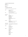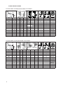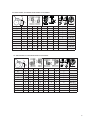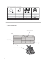
1
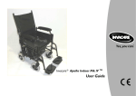
User Manual
English
pirea 4
R
®Invacare Rea AB
Every effort has been made to ensure that the contents of
this publication are updated at the time of printing. As part
of the ongoing improvement of our products, Invacare Rea
AB reserves the right to modify existing models without
prior notice. Any use of this publication, or parts thereof, as
well as any reproduction of images, must have the written
consent of Invacare Rea AB.
2
Contents
1. General
1.1 Introduction
1.2 Symbols
1.3 Guarantee
1.4 Guarantee limitations
1.5 Copyright
1.6 Customer services
1.7 Accidents/incidents
1.8 Testing
1.9 Intended use Rea Spirea4 NG
4
4
4
4
4
4
4
4
4
4
2. Safety
2.1 Lifting the wheelchair
2.2 Daily performance check
2.3 Specific risks
5
5
5
5
3. Technical data
3.1 Dimensions and weight
3.2 Upholstery and frame colours
3.3 Equipment and options
3.4 Seat height tables
3.5 Serial number label
6
6
7
7
8
11
4. Starting to use the wheelchair
4.1 Delivery check
4.2 Wheelchair overview
Assembly
Settings
Angle-adjustable leg rests
Fixed leg rests
Foot plates/calf pads
Seat
Back rest
Back angle
Brakes
Arm rests
Drive wheel settings
Castor wheel adjustments
11
11
11
12
14
14
14
15
16
16
17
18
19
20
24
Accessories
Anti-tip device
Push handles
Amputee leg rest
Head rest
Neck rest
One arm drive
Pelvic belt
25
25
26
27
27
28
29
30
Transport of wheelchairs
and users in vehicles
31
Safety instructions/
propelling techniques
35
Maintenance
37
3
1. General
1.1 INTRODUCTION
This model has been designed to offer you all
the features and functions you might need. After
thorough inspections of the entire manufacturing
process, we have only selected quality components for your wheelchair.
This user manual describes what your wheelchair
can do as well as the maintenance work and adjustments you and your carer can carry out.
However, technical knowledge is required for
making repairs (except for the inner tubes) and
certain adjustments. This must therefore be done
by your supplier.
The Rea Spirea4 NG is designed for both indoor
and outdoor use and to help people who are
unable to walk long distances.
Even though your Invacare wheelchair has
been designed to work for a long time without
problems, it is inevitable that wear and tear
as well as daily use will eventually lead to the
product becoming unusable. Invacare estimates
that this product’s average lifetime is five
years, provided that the product is maintained
correctly according to the manufacturer’s
recommendations.
1.2 SYMBOLS
This symbol means warning and
is used in the manual to point out
information which is very important
in order to avoid personal injury or
damaging the product.
1.3 GUARANTEE
We provide a two-year guarantee for the
Rea Spirea4 NG from the delivery date.
1.4 GUARANTEE LIMITATIONS
Invacare Rea AB accepts no responsibility for injuries or damage due to:
Failure to follow the user manual
Incorrect use
Wear damage to e.g. upholstery, tyres, tubes,
hand rims and castor wheels is not covered by
the guarantee.
Incorrect assembly or installation after the
wheelchair has left the factory
Technical modifications
Unauthorised modifications and/or the use of
generic spare parts
Damage caused by users weighing more than
the specified user weight for each model is
excluded
Written consent from Invacare Rea AB must be
granted before any work or adjustments, apart
from those specified in the user manual, are made
to the wheelchair.
4
1.5 COPYRIGHT
®Invacare Rea AB
Every effort has been made to ensure that the contents
of this publication are updated at the time of printing.
As part of the ongoing improvement of our products,
Invacare Rea AB reserves the right to modify existing
models without prior notice. Any use of this publication,
or parts thereof, as well as any reproduction of images,
must have the written consent of Invacare Rea AB.
1.6 CUSTOMER SERVICES
For contact details see the last page where you will find
addresses for all European sales units.
1.7 ACCIDENTS/INCIDENTS
Since this is a CE marked product, you are asked to
immediately inform your Invacare office of any nearaccidents or accidents caused by this wheelchair and
which could have led to or has led to personal injury.
The relevant authority must also be notified.
1.8 TESTING
The Rea Spirea4 NG has been tested and approved by
TÜV in Germany and is CE marked in accordance with
the Medical Devices Directive.
1.9 INTENDED USE REA SPIREA4 NG
The Rea Spirea4 NG is a manual wheelchair for those
who actively use their wheelchair for long periods of
time (several hours in a row), for shorter periods of
time or for transportation purposes.
The Rea Spirea4 NG is intended for users who are able
to propel the wheelchair by themselves but also for
those who need someone to push the wheelchair.
The Rea Spirea4 NG has features and accessories which
allows the user to sit comfortably for several hours a
day.
Depending on the castor size (125-200 mm), the Rea
Spirea4 NG can be used both indoors and outdoors.
We recommend the larger castor wheels if you often
use the chair on uneven surfaces.
Note that the Rea Spirea4 NG can tip when used on
a slope, especially if the slope is 8º or more. Use the
anti-tip devices (and common sense)!
The Rea Spirea4 NG is designed to be used in combination with a seat cushion placed on the seat. Without a
seat cushion there is a risk of pressure sores.
The Rea Spirea4 NG should always be equipped with
leg rests if it is not propelled with the feet, and has a
low seat height.
2. Safety
2.1 LIFTING THE WHEELCHAIR
2.3 SPECIFIC RISKS
Listed below are several points which affect your own
safety. Read this carefully. Invacare is only responsible
for product changes carried out by authorised personnel. We reserve the right to make any changes to
equipment and specifications without prior notice.
Always lift the wheelchair at the points shown in the
diagram. Never lift the wheelchair by the detachable
arm rests or leg rests. Ensure that the back rest and
push handles are secured in place.
See also the chapter Safety instructions/Propelling
techniques.
Note that the wheelchair should not be lifted by the
back rest bar.
2.2 DAILY PERFORMANCE CHECK
Check that the following parts have been correctly
assembled on the wheelchair:
;
<
"
=
*
<.
By respecting the CE marking, combinations with other
products with combination agreements with Invacare
Rea are allowed. Contact Invacare Rea for a list of
suppliers.
Other adjustments carried out by the customer shall be
deemed as a ”specially adjusted product” which means
this must be documented and the customer takes over
responsibility.
Failure to comply with the instructions may result in
personal injury and/or damage to the product.
- that all parts are securely fastened to the frame
- that all wheels and knobs are properly tightened
- that all brakes and anti-tip devices function cor
rectly
- that the back rest and push handles are properly
secured
- that the wheelchair is stable and that there is no
risk of tipping.
or foot rests.
of the chair.
out of the chair as there is a risk of the chair tipping
over.
this may cause injury to the hands.
ping.
"#
$
the surface is wet, slippery or when on a slope.
% securely attached.
&
sitting in the chair.
'
are slackened, the greater the risk of the wheelchair
tipping.
*+
long periods at a time can reach a temperature
higher than 41°C.
5
3. Technical data
3.1 DIMENSIONS AND WEIGHT
Seat width
35,5/38/40.5/43/45.5/
48/50.5 cm
Leg rest length
32–53 cm
Total depth
92-117 cm
6
Seat depth
40, 45, 50 (-5) cm
Seat angle settings
Seat height
38,5–51 cm
Back rest height
Arm rest height
35-55 cm
19–29 cm
Back angle settings
Total width
0°– 6°
-6° - +13°
Seat width + 20 cm
Collapsed width
Weight
Max. user weight
16 kg
max 135 kg
30,5 cm
Total height
72-122 cm
Crash test
3.2 UPHOLSTERY AND FRAME COLOURS
Upholstery
Black Jemima TR18
Frame colour
Slate-grey
3.3 EQUIPMENT AND OPTIONS
The Rea Spirea4 NG has a wide range of accessories and options.
Back
Back with adjustable angle
Fixed back
Fixed back upholstery
Removable back upholstery with cover
Seat
Sling seat depth adjustable 5 cm
Sling seat depth (5 cm) and tension adjustable.
Seat cushion
5 cm
Leg rests
80º leg rests
Angle-adjustable leg rests
Plaster leg rest
Amputee leg rest
Fixed foot plate
Whole foot plate
Angle and depth-adjustable foot plate
Heel strap
Calf strap
Arm rests
Side guards
Height adjustable arm rests, long or short pad
Hemiplegic arm rest
Comfort arm rest, long or short pad
Castor wheels
125-200 mm, pneumatic or solid, wide or narrow
Drive wheels
16”, 22”, 24”, pneumatic, solid or puncture-proof
Camber 0º or 2º
Brake
User brake
Carer-operated brake
One-arm brake
Extended brake arm
Others
Several types of hand rim
Spoke guards
Anti tip devices
Reflectors kit
Table tray
Pump
Cane holder
Tool kit
External push handles
Safety belt
Back rest bar
Neck rest
Head rest
7
3.4 SEAT HEIGHT TABLES
22'' DRIVE WHEEL, STANDARD DRIVE WHEEL ATTACHMENT
SA
5
3
SH
(cm)
4
SH (cm)
SA
SD40
SD45
SD50
SD40
38,5
41
3°
3°
3°
3°
3°
3°
3°
3°
3°
3°
3°
5
4
4
3
3
2
2
2
1
1
1
5
4
4
3
3
2
2
2
1
1
1
5
4
4
4
3
3
2
2
2
1
1
5
4
4
3
3
2
2
2
1
1
1
43,5
46
48,5
3
2
1
2
SD45
5
2
1
7
5
3
6
4 35
1
4
2
SD50
D
mm
120 (5")
4
3
3
2
5
4
4
3
3
2
2
1
-
7
5
5
3
2
2
-
3
2
2
-
5
1
1
-
1
150 (6")
140 (5,5")
150 (6")
140 (5,5")
150 (6")
200 (8")
140 (5,5")
1
1
1
-
1
150 (6")
1
-
3
200 (8")
4
120 (5")
22'' DRIVE WHEEL, ACTIVE DRIVE WHEEL ATTACHMENT
SA
SH
(cm)
SH (cm)
SA
SD40
SD45
SD50
SD40
38,5
41
3°
3°
3°
3°
3°
3°
3°
3°
3°
3°
3°
5
4
4
3
3
2
2
2
1
1
1
5
4
4
4
3
3
2
2
2
1
1
5
5
4
4
3
3
2
2
2
1
1
5
4
4
3
3
2
2
2
1
1
1
43,5
46
48,5
8
7
5
3
2
1
SD45
5
6
4 35
1
SD50
4
2
D
mm
120 (5")
4
3
3
2
5
4
4
3
3
2
2
1
-
7
5
5
3
2
2
-
3
2
2
-
5
1
1
-
1
150 (6")
140 (5,5")
150 (6")
140 (5,5")
150 (6")
200 (8")
140 (5,5")
1
1
1
-
1
150 (6")
1
-
3
200 (8")
4
120 (5")
24'' DRIVE WHEEL, STANDARD DRIVE WHEEL ATTACHMENT
SA
5
3
4
3
2
1
2
SH
(cm)
SH (cm)
SA
SD40
SD45
SD50
SD40
41
43,5
3°
3°
3°
3°
3°
3°
3°
3°
3°
3°
5
4
4
3
3
3
2
2
2
1
5
4
4
3
3
3
2
2
2
1
5
5
4
4
3
3
3
2
2
1
5
4
4
3
3
3
2
2
2
1
46
48,5
51
SD45
5
7
5
3
6
4 35
1
D
4
2
SD50
mm
150 (6")
4
3
3
3
5
4
4
3
3
3
7
5
5
3
3
5
2
2
1
2
2
1
2
2
3
150 (6")
140 (5,5")
150 (6")
200 (8")
140 (5,5")
150 (6")
200 (8")
1
1
1
200 (8")
4
140 (5,5")
24'' DRIVE WHEEL, ACTIVE DRIVE WHEEL ATTACHMENT
SA
7
5
3
SH
(cm)
SH (cm)
SA
SD40
SD45
SD50
SD40
41
43,5
3°
3°
3°
3°
3°
3°
3°
3°
3°
3°
5
4
4
3
3
3
2
2
2
1
5
5
4
4
3
3
3
2
2
1
5
5
4
4
3
3
3
2
2
1
5
4
4
3
3
3
2
2
2
1
46
48,5
51
SD45
5
6
4 35
1
SD50
4
2
D
mm
150 (6")
4
3
3
3
5
4
4
3
3
3
7
5
5
3
3
5
2
2
1
2
2
1
2
2
3
150 (6")
140 (5,5")
150 (6")
200 (8")
140 (5,5")
150 (6")
200 (8")
1
1
1
200 (8")
4
140 (5,5")
9
16'' STANDARD DRIVE WHEEL ATTACHMENT
2
1
cm
46
7
5
3
2
2
2
1
50
6
4 35
1
4
2
3
3
5
1
D
mm
140 (5,5")
150 (6")
200 (8")
200 (8")
3.5 SERIAL NUMBER LABEL
Date of manufacture
Model
INVACARE International SARL
Serial number
Max. user weight
Positioning
The serial number label is placed here.
10
4. Starting to use the wheelchair
4.1 DELIVERY CHECK
Check that all parts comply with the delivery note.
Any damage incurred during transport should be
reported immediately to the delivery company.
Retain all packaging until the transport company has
inspected the consignment and an agreement has
been reached.
4.2 WHEELCHAIR OVERVIEW
1
13
2
12
11
3
10
4
9
5
8
7
6
1. Backrest upholstery
2. Arm rest
3. Seat
4. Leg rest
5. Foot plate
6. Castor wheel
7. Castor housing
8. User brake
9. Hand rim
10. Drive wheel axle
11. Drive wheel attachment
12. Drive wheel
13. Backrest
11
ASSEMBLY
1.
1. Attach the drive wheels by pressing the button in
the centre of the wheel while you slide the axle
into the drive wheel plate.
At this stage it is important that you check that
the locking pin has actually locked the wheels
into position.
Take hold of the wheels and try to detach them.
This should NOT be possible.
2.
2. Unfold the wheelchair by taking the seat’s edges
and pressing these outwards/downwards.
Be careful not to trap your fingers between
the seat and frame tube.
If you have a back rest bar, fold it up into position.
3.
3. Lower the detachable arm rests in their brackets
on the frame.
Do not put your fingers on the seat frame.
4a.
4a. Foot rests
Attach the foot rests by pushing the pin at
the upper part of the foot rest down into the
wheelchair’s frame tube. The foot rests must be
angled outwards when they are inserted.
Lock the foot rests by turning them inwards. The
foot rests are automatically locked so that there
is no risk of them coming off the wheelchair.
Be careful not to trap your fingers between
the frame and foot rest.
12
4b.
4b. Leg rests, angle adjustable
Attach the leg rests by pushing the pin at the upper
part of the leg rest down into the wheelchair’s
frame tube. The leg rests must be angled outwards
when they are inserted.
Lock the leg rests by turning them inwards. The
leg rests are automatically locked so that there is
no risk of them coming off the wheelchair.
Be careful not to trap your fingers between
the frame and leg rest.
13
SETTINGS
ANGLE-ADJUSTABLE LEG RESTS
Angle-adjustable leg rests support the legs and reduce
pressure. The leg rests can be used for bandaged legs
but not for legs in plaster casts. The leg rests must
always be fitted with calf pads, foot rests and heel
straps.
1.
It is important to adjust the height and angle to get
the best seating position possible.
A
Tool: 5 mm Allen key
1. Adjusting the leg rest height
Adjust the leg rest’s height by loosening screw
(A) with an Allen key. Adjust the leg support to
a suitable height and the screw catches in one of
the recesses on the leg rest tube. Then retighten
the screw.
2.
B
2. Leg rest angle
Pull lever (B) with one hand while supporting the
leg rest with your other hand. When a suitable
angle is obtained, let go of the lever and the leg
rest will lock into one of seven preset positions
(C).
Do not put any heavy objects or let children sit
on the leg rest. It can damage the mechanism.
C
The distance between the lowest part of the
foot plate and the ground must be at least 40
mm.
FIXED LEG RESTS
Adjusting the foot rest height
Adjust the foot rest’s height by loosening screw (A)
with an Allen key. As you adjust you will hear ”clicks”.
One ”click” is equivalent to one height level. Adjust
the foot support to a suitable height and the screw
catches in one of the recesses on the leg rest tube.
Then retighten the screw.
C
A
14
NB! Do not touch the upper screw (C).
The distance between the lowest part of the
foot plate and the ground must be at least 40
mm.
FOOT PLATES/CALF PADS
1. Angle-adjustable foot rests
Adjust the angle and depth of the foot rest by
loosening the screw (A) with a 5 mm Allen key.
You can then easily adjust the foot plate to the
correct position.
1.
Do not place anything on the foot plate when
the screw is loose.
A
Tool: 5 mm Allen key
C
D
2.
B
2. Calf pads
The calf pads can be fitted in two different depth
positions. Swing the pad forwards. Loosen the
screw (B) with an Allen key. Move the large nut
(C) from the reverse side and place it in the other
attachment hole. Move the calf pad to the new
position and secure it in place with the screw.
The height of the calf pads can easily be adjusted
using the hand wheel (D).
Tool: 5 mm Allen key
3.
A
3. Foot rest one-piece
Adjust the angle and depth by loosening the two
screws (A) by the foot rest fastener with a 5 mm
Allen key. Adjust the foot rest to the correct
position and tighten the screws.
Do not put anything on the foot rest when
the screws are loose.
Tool: 5 mm Allen key
The foot rest can be folded up. Lift the left side of
the foot rest upwards.
Be careful not to trap your fingers between
the foot rest and the support when you fold
it down.
15
SEAT
1. Adjusting the seat depth
Fold the chair slightly by lifting the seat upwards.
The front part of the seat is attached with Velcro
straps from the back part of the seat. Pull up the
Velcro strap and adjust by pulling the side of the
seat forwards or backwards in the rails on the side
tubes. Check that the adjustment is even on both
sides.
1.
When you have finished, fold the chair right out
again and then attach the Velcro strap in the back
part of the seat.
2.
2. Adjusting the shape
Pull back the seat’s upper section so that the adjustable Velcro straps are visible. Use these straps to
adjust the seat. Always have a cushion on the seat
when testing if the shape is correct.
The depth of this seat can also be adjusted in the
same way as the fixed seat.
BACK REST
Adjusting the back rest height
1. Cut off both plastic ties (A) at the bottom of the
back upholstery with a pair of scissors. Then fold
the chair slightly by lifting the seat upwards. Or
loosen and fold the back upholstery forwards
1.
A
2
B
Tool: 5 mm Allen key
16
2. Loosen the screws (B) on the reverse side of the
back tubes with an Allen key. Now it is possible
to raise and lower the back. Tighten the screws
again.
When the adjustment is complete, secure
with new plastic ties on the back of the back
upholstery if you have a fixed back upholstery.
Tighten them properly!
3. Adjustable back
The shape of the back can be adjusted with Velcro
straps.
The user must sit in the chair when the back is
being adjusted. The shape can be adjusted to satisfy
the existing support and comfort needs by using
the Velcro straps. The straps in the lumbar region
can for example be tightened to provide good
support in the curve of the back and allow a more
upright sitting position. When all adjustments are
complete, fold the back upholstery back into place
and secure it with the Velcro straps.
3.
Back angle
A
Loosen the screw (A) on the inside and the screw
(B) on the outside of the back tube. Angle to the
desired position by turning the eccentric washer (C)
(between 6º forward or 13º backward) with your hand
or an Allen key. Tighten the screws again. Repeat this
procedure on the opposite side.
B
C
17
BRAKES
User brake
A
To engage the brake, move the lever (A) forwards.
To release the brake, move the lever backwards
(towards you).
Be careful not to trap your fingers between
the brake shaft and tyre.
Adjusting the brake
1. First check that the tyres are inflated to the correct
air pressure (you will find this on the tyre wall).
Then loosen the screws (B) with an Allen key, slide
the brake to the desired position and tighten. The
correct distance between the brake shaft (C) and
the tyre must be approx. 5 mm.
Incorrect adjustments or use of the brake can
reduce the braking effect.
C
B
Tool: 5 mm Allen key
Carer-operated brake
1. Applying the brake while moving: pull both brake
handles upwards and the chair will come to a
stop.
1.
2.
2. To lock the brakes: pull the brake handle and move
the lock catch (A) downwards. Then let go of the
handle.
A
3.
3. To release the brakes: pull the brake handle and
the lock catch will release automatically.
Incorrect adjustments or use of the brake can
reduce the braking effect.
18
ARM RESTS
1.
Adjusting the arm rest height
1. Detachable arm rests
If your wheelchair is equipped with arm rests that
can be raised or lowered, you easily adjust the
height by pulling up the arm rest and loosening the
screw (A) under the arm rest. Move the screw up
or down to the desired position and retighten the
screw. Lower the arm rest again.
A
Tool: 5 mm Allen key
Be careful not to trap your fingers between
the side support plate and the frame when you
adjust the height.
2.
B
2. Adjust the height of the arm rests by turning the
knob or loosening the screw (B), setting the desired height and then re-tightening the knob or the
screw.
Be careful not to trap your fingers between the
arm rest pad and the side support plate when
you adjust the arm rest height.
Tool: 5 mm Allen key
19
DRIVE WHEEL SETTINGS
A
Adjustable attachment for drive wheels.
B
With the attachment you can set five height positions and three lengthwise positions.
A:
B:
C:
D:
C
Standard - standard design
Passive - set backwards for better stability
Active
Position for double amputees for increased stability
and in order to prevent the amputee from tipping
backwards.
Adjustments to the wheels’ position and/
or fork angle must be carried out under the
supervision of an expert who has made a
complete risk assessment of the effect this
change will have on the wheelchair’s function.
Ask your adviser.
D
The tip risk increases if the rear wheels are
located in front of the backrest. Use anti-tip
devices.
E
Changing the position of the drive wheel
attachment
The attachment can be moved up and down and be
turned to obtain different seat heights. Loosen screws
and nuts (E). Change the position of the drive wheel
attachment. Tighten screws and nuts.
When the wheels have been mounted in the
correct position, it is important to check
that screws and nuts have been tightened
properly.
Changing the position of the wheel on the
attachment
To change the position of the drive wheel on the
attachment, first remove the wheel by pressing the
quick release (F) on the axle and pull. Loosen the nut
(G) and move the axle housing (H) to the new position. Tighten screws and nuts.
F
H
G
When you have fitted the wheels in the correct position, it is important that you check
thoroughly that the nuts and screws are
tightened securely. The axle housing should
be tightened with a manual and dynamometric wrench calibrated to 40Nm. This is
important for your own safety!
Always remember to adjust the brakes, when
the rearwheel position has been changed.
20
Changing camber
The parts (A) of the drive wheel attachments that are
fastened to the frame are shaped assymetrical (B) with
a wider and a narrower upper and lower part. This
gives the opportunity to camber the drive wheels 0°
or 2° depending on how the drive wheel attachments
are fastened to the frame.
B
A
When the drive wheel attachments are mounted (forwards or backwards, see previous page) it is the outer,
lower part (C) of the attachments that decides the
camber of the rearwheels. The picture illustrates drive
wheel attachments that give 0° camber. If the wider
part of the attachment had been placed downwards
the camber would have been 2° instead.
C
C
2°
0°
D
The drive wheel attachments for active and double
amputee positionings have a marking (D) to facilitate
camber settings. When the marking is placed on the
upper (out)side of the attachment, the camber is 0°.
For 2° camber the attachment should be mounted
with the marking on the lower part of the attachment.
21
DRIVE WHEEL SETTINGS - CARER-OPERATED BRAKE
1.
1. Remove the drive wheel by pressing the button
(A) on the wheel hub and pulling the drive wheel
right out. Loosen the nut (B). Remove the brake
unit from the drive wheel attachment.
A
B
Tool: 22 mm fixed spanner
2.
C
D
Tool: 5 mm Allen key
2. See the illustration (2) for the how the brake unit
should be placed on the different drive wheel
brackets.
Note that the brake unit has two different points of
attachment, one upper (C) and one lower (D).
22
3.
3. Place the brake unit in its new position. Make sure
that the wire attachment (F) points upwards.
Tighten properly.
F
23
CASTOR WHEEL ADJUSTMENTS
1.
1. When you have found the seat height and seat
angle you are happy with, it is important for the
chair’s propelling ability to check that the angle
between the castor attachment and the ground
is 90°.
2.
2. Adjusting the angle
Loosen the screws (A) approx. two turns. Adjust
the castor housing to the correct angle by turning
it. On the inside of the castor housing there are
grooves that make it possible to adjust to 0°, 3° or
6° angles. When the castor housing is parallel to
the tube, the angle is 0°. Do not forget to tighten
the screws when you have reached the desired
angle.
A
Check that the castor housing is fastened
properly after the adjustment.
Tool: 5 mm Allen key
3.
A
3. Adjusting the height
Loosen the lower of the two screws (A) completely.
Loosen the upper screw approx. two turns.
Move the castor housing upwards.
Re-tighten the lower screw, although not completely.
Adjust the angle according to step 2 above.
Tighten both screws.
Check that the castor housing is fastened
properly after the adjustment.
0
24
Accessories
1.
Anti-tip device, rotatable
The anti-tip device is foldable and both its height and
depth can be adjusted. Please pay particular attention
to how the anti-tip device is positioned when it is used.
There will be a warning sticker if the anti-tip device
has not been activated.
A
1. Assembly
Insert the two screws (A) into the holes of the
castor wheel attachment and fit them into the
holes of the anti-tip device. The height of the antitip device is adjusted according to the holes that
are used. Screw tightly.
Tool: 5 mm Allen key
2.
2. Adjusting the height
To adjust the height, press on the two buttons (B)
on each side of the housing and pull the tube (C)
to the desired position (hole). The buttons will
lock the tube in the correct place.
B
Do not use the buttons (B) to fold up the
anti-tip device.
C
3. Adjusting the depth
The depth is adjusted by pressing the button (D)
and pulling the tube to the desired depth. The
button will lock the tube in the correct place.
D
4.
E
The distance between the anti-tip device and
the ground as well as the distance between
the anti-tip device and the drive wheel should
be 5 cm.
4. Swing mechanism
To turn the anti-tip device under the wheelchair,
press down the ”hub” (E) and pull it to one side.
NB! A red sticker warns of a tipping risk.
To activate the anti-tip device turn it back into
place again. It will automatically lock into the right
position.
NB! _When the anti-tip device has been correctly
activated the red sticker will be concealed.
Use your foot to fold up the anti-tip device. If you
use your hands there is a risk of getting them stuck
between the device and the tube.
Always use two anti-tip devices!
Do not forget to fold out the anti-tip devices. The
wheelchair can tip over!
Check that the anti-tip devices are locked properly
before use.
25
Anti tip device
1-2.
The anti-tip device is also used as a step tube. It is
easy to adjust the height.
1. Remove the plastic plugs from both the step tubes/
back frame parts. Push the anti-tip device into place
and screw tightly with the nut (A) and screw (B).
B
2. Pull the spring-loaded plastic washer back and slide
the anti-tip device to the desired position. Make
sure that the anti-tip device is secure in the new
position.
Always remember to fold down the anti-tip
devices again when you have had then folded
up.
A
Tool: _4 mm Allen key
10 mm socket spanner
PUSH HANDLES
Adjusting the push handles
1.
1. If your wheelchair has push handles that can be
raised and lowered you can easily change the height
by loosening the knob, setting it to the desired
height and tightening the knob.
2.
A
26
2. When the hole (A) is visible, at the top edge of
the attachment, the handle will be in the correct
”lock position”.
AMPUTEE LEG REST
1.
A
B
1. Attach the leg rests by pushing the pin at the upper
part of the leg rests down into the tubes on the
wheelchair. You must angle the leg rests outwards
when you insert them. By twisting the leg rests
this way they will lock and there will be no risk of
them coming off the wheelchair.
2. Loosen the screw (A) on the cushion’s mounting
to adjust the cushion’s angle and depth. Loosen
the screws (B) to adjust the height.
When using the amputee leg rest, the balance
of the wheelchair changes. The risk is minimised
by moving the drive wheels backwards in the
drive wheel attachment and by using the passive
or double amputee drive wheel attachments.
See chapter on Drive wheel settings.
Tool:
5 mm Allen key
HEAD REST
1.
1. Use the hand knob (A) to adjust the height of and
remove the head rest. The tube is equipped with
a ”memory ring”. Loosen the screw (B), adjust,
and tighten.
B
A
Tool:
5 mm Allen key
2. Adjust the angle and depth with two screws (C)
and the handle (D). Loosen and adjust.
2.
C
D
Tool:
5 mm Allen key
27
3.
3. Adjust the sides by loosening the screw (E). Adjust
and tighten the screw again.
E
Tool:
5 mm Allen key
4. To change the angle of the wings, loosen the screw
(D). Adjust and tighten.
4.
D
Tool:
5 mm Allen key
1.
NECK REST
1. Use the hand knob (A) to adjust the height of and
remove the neck rest. The tube is equipped with
a ”memory ring”. Loosen the screw (B), adjust,
and tighten.
B
A
Tool:
5 mm Allen key
2.
C
D
Tool:
28
5 mm Allen key
2. Adjust the angle and depth with two screws (C)
and the handle (D). Loosen and adjust.
ONE ARM DRIVE
A
The one arm drive enables you to move the wheelchair with one hand. Two hand rims are installed on
the same wheel. The drive wheel can be fitted on the
right or left side.
1a. Remove the drive wheel
Remove the drive wheel by pulling the button (A)
and pulling the wheel off the wheelchair.
1b. Fitting the drive wheel
When you put the wheel back, pull the button (A),
upwards and secure the drive wheel to the hub.
It is very important that you check that the lock
catch has actually locked the wheel when you
let go of the button. Test this by trying to pull
the wheel off. This should NOT be possible.
The hand rims can either be placed flush to each other
(internal position) or with the inner, smaller, hand rim
sticking out (external position).
C
2. Changing the hand rim’s position.
Loosen the three screws (B), take off the hand rim
and turn it over. Put the hand rim back and screw
the screws tight again.
Be careful when you remove the telescopic
drive shaft. Point it away from your body
when you release the powerful steel spring
found inside.
NB! The drive shaft (C) is an important part of the
wheelchair. Without this part the user would be
unable to move the wheelchair.
B
D
Be careful not to get your fingers trapped between the drive wheel’s spokes and the outer
hand rim’s three brackets (D).
Tool: 4 mm Allen key
10 mm socket spanner
29
PELVIC BELT
The pelvic belt is used to avoid the risk of sliding out
of the chair and to maintain a good posture.
Check that the user is sitting right back in the wheelchair and that the back is as upright and symmetrical
as possible - not slanted to one side or tipped backwards.
Position the belt so that the hips can be seen above the
belt. Adjust the length with the plastic buckles so that
there is just room for one hand between the body and
the belt. We recommend placing the lock in a central
position, i.e. adjusting the length on both sides. These
adjustments should be checked and possibly changed
every time the belt is used.
Fasten the belt on the frame with a screw and nut as
in the illustration.
A
If the belt has come loose at the metallic clasp it should
be threaded according to the pictures a-c. Make sure
that the belt cannot slide.
B
C
Thread the belt through the two plastic buckles as
shown in the picture. It is important that both buckles
are used. There is a danger the belt might slip if the
belt is threaded through only one.
30
Transport of wheelchairs and users in
vehicles
Our wheelchairs are designed to offer the user as much comfort and safety as possible when using them in
many different situations in their daily life. This means that compromises must be made for the product to be
usable. When transporting by car it is always safest to sit in the car’s normal seats and use the car’s ordinary
seatbelts which are only designed for car transport You should sit in the car’s normal seats and use the car’s
seatbelt if possible. If for some reason it is completely impossible to travel in some other way, you may be
transported in the wheelchair provided that the requirements and regulations below are followed.
Although Invacare Rea’s products and regulations below are designed to increase safety when being
transported in vehicles, passengers can still be injured if there is a crash or other near-accident. Invacare cannot
make any guarantees as to what may happen in the event of incidents during transport in vehicles.
The wheelchair has been tested and approved according to the 7176-19 standard using a normal setting and
normal configuration.
1.
1. Wheelchairs with users must be transported facing
forwards in the vehicle’s direction of travel. All
additional equipment such as tables, body support,
abduction pillows, etc. must be taken off before
travelling and stored so that they will not cause
any damage in the event of a near-accident.
2.
2. The wheelchair must be secured in the vehicle with
a four-point strap system. The user must wear
a three-point safety belt fastened in the body of
the car. Both must be approved according to ISO
10542-2. The wheelchair seat must be flat and the
back must be as vertical as possible.
3.
3. The points of attachment on the wheelchair where
the tie straps must be secured are marked with
this symbol.
31
4.
4. For a wheelchair to be used for transport in vehicles, it must be equipped
with a pelvic belt.
5.
5. The car’s safety belt must be as tight as possible
against the user’s body without being uncomfortable. The upper parts of the belt must lie against
the user’s shoulder. No part of the belt must be
twisted.
6.
A
7.
6. The middle section of the car’s safety belt must
be fixed around the user’s pelvis so that the angle
of the pelvic belt is between 30° and 75° from the
horizontal level. The higher the angle, the better,
although never higher than 75°.
7. The safety belt should not be separated from the
user’s body by parts of the wheelchair such as arm
rests, wheels, etc.
8.
8. The neck rest must be attached to the wheelchair
and set at a high level.
32
A
RESTRAINT METHODS
A. Front restraints with straps
1. Connect the front straps around the front part of
the chair’s frame.
2. Release the wheelchair’s brakes and tighten the
front straps by pulling the chair backwards.
3. Brake the chair.
B. Fastening at the back
1. Attach the snap hooks in the transport bracket by
the back rest attachment.
2. Tighten the straps.
C. Fastening the pelvic belt and safety belt
1. Check that the pelvic belt is securely fastened.
2. Fasten the car’s safety belt over the user.
Note that the Rea Spirea4 NG should not be
used for seated transport in a vehicle if the
wheelchair is not equipped with transport
brackets (A) and does not have a neckrest
fitted
33
HOW TO DISASSEMBLE YOUR WHEELCHAIR AHEAD OF TRANSPORT AS LUGGAGE.
When you want to transport the Rea Spirea4 NG,
you can easily remove certain parts to make the chair
smaller and lighter.
1.
1. Start by removing the arm rests.
Press in the button on the spring to loosen the arm
rest and then lift it straight up.
2a.
2a. Release the foot rests by moving the lever (B)
forward or towards the sides while angling the
rests outwards. You can then easily lift off the
foot rests.
B
Be careful not to trap your fingers between
the frame and the foot rest.
2b.
C
2b. Loosen the leg rests by pressing in the lever (C)
and turning the leg rests outwards. You can then
easily lift off the leg rests.
Be careful not to trap your fingers between
the frame and the leg rest.
3.
3. Press the seat into a U shape. Take hold of both
sides of the seat frame and fully collapse the
wheelchair. If you have a back rest bar, remove it
first by pressing in the catch on the inside of the
left bracket and then folding the bar down.
4.
34
4. Remove the drive wheels by pressing the button
in the centre of the wheel while pulling the wheel
away from the wheelchair. Finally, fold the anti-tip
devices upwards.
Safety instructions/propelling techniques
We recommend that you get your wheelchair tested by a qualified person who will make the adjustments you
desire and also takes your build and needs into account. We also hope that you have received help with how
best to use the chair. Start by carefully practising until you are familiar with the wheelchair’s possibilities and
limitations.
Moving to and from the wheelchair
Propel the wheelchair as close as possible to the seat you want to move
to. Apply the brakes. Remove/flip up the arm rests and detach the leg
rests/move them outwards. Do not put any of your weight on the foot
plates, as the chair may tip forwards.
When moving from the wheelchair do not place your fingers between the frame tube and seat tube.
Stretching and bending
Position the wheelchair as close as possible. When you stretch and bend,
your back must always be in full contact with the beck rest, otherwise the
wheelchair may tip over. Stretching backwards over the back rest is not
recommended.
Propelling up a slope
Many experienced users manage to propel up a slope by themselves. In
order not to lose control of the steering and to avoid tipping backwards,
you should always lean forward while propelling up a slope. Propel the
wheelchair forwards using short and quick strokes to the hand rims in
order to maintain speed and steering control.
Generally help is needed when you come to steep slopes.
If you have to stop on a slope, it is particularly important that you do not
make any sudden or unexpected backward movement when you start
moving the wheelchair forwards again. As the wheelchair is already leaning backwards, such a movement can cause the wheelchair to tip backwards.
Be careful not to trap your fingers between the brake shaft and
the tyre.
Propelling down a slope
We recommend that you have one or more assistants when going down
steep and wet slopes.
First check the slope to see if there are any particular risks, such as potholes, slippery sections, etc. Never use your block brake to slow down.
When you apply the brake on a downward slope, the wheels lock and
the wheelchair can suddenly pull to one side, tip sideways or stop immediately, throwing you out of the chair. Always control the speed with the
hand rims. Remember that the hand rims may become hot due to friction
and this may cause injury to the hands. Try to propel down the slope in a
straight line as much as possible. Never change direction when propelling
down a slope. Never propel up or down a slope diagonally.
35
Onto a kerb
This method assumes the assistant is always behind the wheelchair and
creates the greatest safety for the user.
The following advice is for the assistant:
Illustration 1
Adjust the anti-tip devices upwards. Ensure that the user’s feet rest
securely on the foot rests and cannot slide off before you lean the
wheelchair backwards and push it forwards against the kerb.
Illustration 2
Lower the front part of the wheelchair onto the pavement and stand
as close to the wheelchair as possible before you lift up the whole
wheelchair.
Illustration 3
Lean forward and lift/roll the wheelchair over the kerb.
Illustration 4
Lower the wheelchair onto the pavement so that the weight is divided
across all four wheels. Ensure that the wheelchair does not roll backwards.
Off a kerb
Follow the procedure above but in reverse order (steps 4, 3, 2 and 1)
to move off the kerb.
Kerbs - Alternative method
This method is generally used by experienced assistants who are
stronger than average. The method can also be used when the kerb or
step is low and only constitutes a minimal obstacle.
The assistant steps backwards onto the pavement and pulls the wheelchair up onto the pavement. It is important for the assistant to use
their body correctly to prevent injury. Tip the wheelchair backwards
and roll the chair over the kerb onto the pavement. Take particular
care if the kerb is wet or slippery.
Escalators
Do not use escalators with a wheelchair. Find out if there is a lift
nearby.
Stairs
We advise you to avoid going up/down stairs in your wheelchair where
possible and instead choose an alternative route.
We recommend that you receive help from two assistants to get up
and down stairs. One assistant goes in front and holds the wheelchair’s
frame and the other goes behind and holds the push handles. Fold the
anti-tip devices upwards. Balance the wheelchair on the drive wheels
until the balance point is found. Then roll the chair step by step down
the stairs by letting the wheelchair roll over the edge of each step. It is
important that assistants remember not to hold detachable arm rests
or leg rests. Assistants much also remember to lift correctly, using
their legs and keeping their back as straight as possible.
36
Maintenance
Care instructions
Overview
#K
QK#
You will find the address and telephone number on the back cover of this manual.
Cleaning
;#XZ
be used. If necessary the upholstery can be washed at 40°C. An ordinary washing detergent can be
used.
Cleaning and disinfection
1. Remove all loose and detachable covers and wash these in a washing machine, following the washing
instructions for each item.
2. Spray the wheelchair with detergent, e.g. car cleaning agent with wax, and let it set.
3. Rinse the wheelchair with a high-pressure spray or ordinary water spray depending on how dirty the
chair is. Do not spray on bearings and draining holes. If you wash the wheelchair in a washing machine
the temperature must not exceed 60°C.
4. Spray the chair with alcohol to disinfect it.
5. Let the chair dry in a drying room. Remove parts where water has gathered, e.g. end parts, ferrules, etc.
If the chair has been washed in a machine, we recommend that you also blow-dry it with compressed
air.
Wheels and tyres
;+
#
=Q
same type of pump used for cars. The recommended air pressure for drive wheels is:
Standard tyres 3.5 bar 50 psi
Low profile tyres
6.5 bar 90 psi
The recommended air pressure for castor wheels is:
(200 mm) 8”
4.0 bar
(150 mm) 6”
2.5 bar
When inflating the tyres there is a risk of explosion if they are inflated too much.
Technical service
[
K\
#
K\
department. You will find the address and telephone number on the back cover of this manual.
Service life
We estimate that the Rea(tm) Spirea4 NG(r) has a service life of five years. It is difficult to state the exact
length of the service life of our products. The length stated is an estimated average service life based
on normal use. The service life may be considerably longer if the wheelchair is used to a limited extent,
and if it is used with care, maintained and handled properly. The service life may also be shorter if the
wheelchair is subjected to extreme use.
Near-accidents
Please inform your Invacare office immediately of any accidents or near-accidents caused by this wheelchair and which could have led to or has led to personal injury.
The relevant authority in your country must also be notified.
37
Claims
Phone customer services (see back cover) if you wish to make a claim and state the reason for the
claim and order a replacement item. You will be given a claim number which the return delivery must
be clearly marked with. When you receive the replacement, return the broken item marked with the
claim number.
Testing
The Rea Spirea4 NG has been tested and approved by the Swedish Handicap Institute and is CE marked
according to the Medical Device Directive.
Recycling
The Rea Spirea4NG can be divided into the following main components:
=
;Q
=
Chassis
The chassis is made from aluminium and is fully recyclable. Recycling aluminium requires only 2-5 % of the
energy used to make new aluminium.
Plastic parts
The plastic parts in the chairs are made of plastic belonging to the ”Thermoplastic” family and are marked
with recycling symbols (where possible because of the part’s size). The main material is polyamide. This
can be recycled or burned in the appropriately approved facilities.
Upholstery
The upholstery is made from polyester fibres, PUR or PVC. The most efficient way to recycle these is to
burn them in appropriately approved facilities.
Wheels, tyres and tubes
^QQ
Q
according to the above.
#
Packaging
All Invacare Rea AB packaging material is developed to fit the products in an optimal way to reduce the
unnecessary wastage of material. All boxes are recyclable.
Contact your local recycling centre to get correct information how to handle the above mentioned materials.
Surface treatment
Lacquered surfaces are lacquered with polyester. Some steel parts are zinc-plated. Un-lacquered aluminium
parts are anodised. Visible wooden parts are lacquered
38
39
Manufacturer:
Invacare Rea AB
Växjövägen 303 S-343 71 DIÖ SWEDEN
Sales Companies:
Danmark:
Invacare A/S, Sdr. Ringvej 37, DK-2605 Brøndby
Tel: (45) (0)36 90 00 00, Fax: (45) (0)36 90 00 01
[email protected] / www.invacare.dk
Deutschland:
Invacare Aquatec GmbH, Alemannenstraße 10,
D-88316 Isny
Tel: (49) (0)75 62 7 00 0, Fax: (49) (0)75 62 7 00 66
[email protected] / www.invacare-aquatec.de
Ulrich Alber GmbH, Vor dem Weissen Stein 21,
D-72461 Albstadt-Tailfingen
Tel: (49) (0)7432 2006 0, Fax: (49) (0)7432 2006 299
[email protected]
European Distributor Organisation:
Invacare, Kleiststraße 49, D-32457 Porta Westfalica
Tel: (49) (0)57 31 754 540, Fax: (49) (0)57 31 754 541
[email protected] / www.invacare.eu.com
España:
Invacare SA, c/Areny s/n, Polígon Industrial de Celrà,
E-17460 Celrà (Girona)
Tel: (34) (0)972 49 32 00, Fax: (34) (0)972 49 32 20
[email protected] / www.invacare.es
France:
Invacare Poirier SAS, Route de St Roch,
F-37230 Fondettes
Tel: (33) (0)2 47 62 64 66, Fax: (33) (0)2 47 42 12 24
[email protected] / www.invacare.fr
Ireland:
Invacare Ireland Ltd, Unit 5 Seatown Business Campus,
Seatown Road, Swords, County Dublin - Ireland
Tel: (353) 1 810 7084, Fax: (353) 1 810 7085
[email protected] / www.invacare.ie
Italia:
Invacare Mecc San s.r.l., Via dei Pini 62,
I-36016 Thiene (VI)
Tel: (39) 0445 38 00 59, Fax: (39) 0445 38 00 34
[email protected] / www.invacare.it
Nederland:
Invacare BV, Celsiusstraat 46, NL-6716 BZ Ede
Tel: (31) (0)318 695 757, Fax: (31) (0)318 695 758
[email protected] / www.invacare.nl
[email protected]
Norge:
Invacare AS, Grensesvingen 9, Postboks 6230,
Etterstad, N-0603 Oslo
Tel: (47) (0)22 57 95 00, Fax: (47) (0)22 57 95 01
[email protected] / www.invacare.no
[email protected]
Österreich:
Invacare Austria GmbH, Herzog Odilostrasse 101,
A-5310 Mondsee
Tel: (43) 6232 5535 0, Fax: (43) 6232 5535 4
[email protected] / www. invacare.at
Portugal:
Invacare Lda, Rua Estrada Velha, 949,
P-4465-784 Leça do Balio
Tel: (351) (0)225 1059 46/47, Fax: (351) (0)225 1057 39
[email protected] / www.invacare.pt
Sverige & Suomi:
Invacare AB, Fagerstagatan 9, S-163 91 Spånga
Tel: (46) (0)8 761 70 90, Fax: (46) (0)8 761 81 08
[email protected] / www.invacare.se
[email protected]
Switzerland:
Invacare AG, Benkenstrasse 260, CH-4108 Witterswil
Tel: (41) (0)61 487 70 80, Fax: (41) (0)61 487 70 81
[email protected] / www.invacare.ch
United Kingdom:
Invacare Limited, Pencoed Technology Park, Pencoed,
Bridgend CF35 5HZ
Switchboard Tel: (44) (0)1656 776200, Fax: (44) (0)1656
776201
Customer services Tel: (44) (0)1656 776222, Fax: (44)
(0)1656 776220
[email protected] / www.invacare.co.uk
Art. No. 1536533-2 2011-07-01
Belgium & Luxemburg:
Invacare nv, Autobaan 22, B-8210 Loppem
Tel: (32) (0)50 83 10 10, Fax: (32) (0)50 83 10 11
[email protected] / www.invacare.be