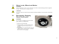
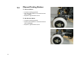
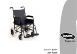
1
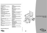
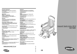
Invacare® Apollo Indoor Mk IV TM
User Guide
Contents
1
2
3
4
5
6
7
Page
Warranty Terms and Conditions…………………………………………………..
5
Standard INVACARE Terms……………………………………………………………………
Limitation of liability………………………………………………………………………………
5
6
Useful Symbols In This Manual……………………………………………………..
Introduction……………………………………………………………………………
4
7
2.1 Intended Use………………………………………………………………………………….
2.2 Type Classification……………………………………………………………………………
8
9
Safety Notes……………………………………………………………………………
10
3.1 Repair or Service Information………………………………………………………………...
3.2 General Safety notes………………………………………………………………………….
3.3 Safety Information On Electromagnetic Interference………………………………………...
3.4 Safety Precautions/Safe Operation…………………………………………………………...
10
11
13
14
Some Useful Tips……………………………………………………………………...
Safety Inspection Checklist………………………………………………………….
Trouble Shooting……………………………………………………………………...
17
21
24
6.1 Trouble Shooting – Mechanical……………………………………………………………….
6.2 Trouble Shooting – Electrical…………………………………………………………………
6.3 Checking Battery Charge Level………………………………………………………………
6.4 Care And Maintenance……………………………………………………………………….
6.5 Product End of Life…………………………………………………………………………...
24
25
27
28
28
Adjustment……………………………………………………………………………..
29
7.1 Seat Depth And Backrest Angle Adjustment (Manual)………………………………………
7.2 Tension Adjustable Back Upholstery…….…………………………………………………..
7.3 Tray Assembly………………………………………………………………………………...
7.4 Lap Belt Adjustment………………………………………………………………………….
29
30
31
32
2
8
34
36
37
38
39
40
41
Batteries………………………………………………………………………………...
42
8.1 Removing/Installing……………………………………………………………………………
8.2 Disconnecting Battery Cables………………………………………………………………...
8.3 Connecting Battery Cables…………………………………………………………………...
8.4 Batteries And Charging……………………………………………………………………….
8.5 Disposing And Recycling Of Used Batteries………………………………………………….
42
45
47
48
51
Motor Locks, Wheels and Brakes…………………………………………………..
52
9.1 Disengaging/Engaging Motor Lock Levers……………………………………………………
9.2 Manual Parking Brakes………………………………………………………………………...
52
53
10
Transportation…………………………………………………………………………
54
10.1Disassembly and folding……………………………………………………………………...
58
59
11
10.2 Transporting your Wheelchair as Luggage…………………………………………
Controls Systems……………………………………………………………………...
68
11.1 Types Of User Control ……………………………………………………………………..
11.2 Joystick Mounting Hardware………………………………………………………………...
68
69
Transfers………………………………………………………………………………...
Keeping Your Chair In Good Condition…………………………………………...
Fault Finding……………………………………………………………………………
Waste Electrical and Electronic Equipment (WEEE) Directive 2002/96/EC...
ISO 7176 Part 15 Requirements For Information Disclosure………………….
Contacting Invacare…………………………………………………………………..
63
65
67
68
69
70
9
12
13
14
15
16
3
7.5 Armrest Adjustment………………………………………………………………………….
7.6 Installing / Removing Backrest Extension……………………………………………………..
7.7 Seating………………………………………………………………………………………...
7.8 Leg Rests…………………………………………………………………………………….
7.9 Elevating Leg Rests…………………………………………………………………………..
7.10 Amputee Supports…………………………………………………………………………...
7.11 Anti Tippers…………………………………………………………………………………
1
Useful Symbols In This Manual
WARNING!
This symbol warns you of danger! Always follow the instructions to avoid injury to the user or damage to the
product!
EXPLOSION HAZARD!
This symbol warns you of an explosion hazard, an example of which can be caused by excessive tyre pressure
in a pneumatic tyre!
• Always follow the instructions to avoid injury to the user or damage to the product.
BURN HAZARD!
This symbol warns you of burns due, for example, to leaking battery acid.
• Always follow the instructions to avoid injury to the user or damage to the product.
NOTE:
This symbol identifies general information which is intended to simplify working with your product and which
refers to special functions.
REQUIREMENTS:
This symbol identifies a list of various tools, components and items which you will need in order to carry out
certain work.
TRANSPORTATION:
This symbol identifies important information relevant to transporting your powered wheelchair in a motor
vehicle.
4
Warranty Terms and Conditions
Standard INVACARE Terms
This is to certify that your powered wheelchair is warranted by INVACARE Ltd. for a period of 2 years for
parts, 3 years for frames and 12 months for batteries.
1. Only INVACARE chairs purchased at full price are warranted against defective workmanship and materials.
2. If a defect or fault is discovered the INVACARE dealer from whom the appliance was obtained should be
notified immediately.
3. The manufacturer will not accept responsibility for damage caused by misuse or non-observance of the
instructions set out in the user manual.
4. During the period of the warranty any parts that have become defective, due to faulty workmanship or
materials, will be renewed or repaired without charge by the INVACARE dealer.
5. The warranty will be forfeited should any unauthorised alteration be made to the equipment.
6. The purchaser’s statutory rights under the Consumer Protection Act are not affected.
5
Limitation Of Liability
This warranty does not extend to the consequential costs from fault clearance, in particular freight and travel
costs, loss of earnings, expenses, etc.
• Natural wear and tear
• Inappropriate or incorrect use
• Defective assembly or setting-up by the purchaser or third parties
• Defective or neglectful treatment
• Use of unsuitable spares
6
2
Introduction
Dear Customer,
First of all we wish to thank you for your confidence in our products. We hope you will enjoy your new
Apollo Indoor Mk IV TM powered wheelchair.
This manual contains important information and hints on:
• Safety
• Operation
• Care and maintenance
The information contained in this document is subject to change without notice.
As a manufacturer of wheelchairs, INVACARE endeavours to supply a wide variety of wheelchairs to meet
many needs of the customer. However, final selection of the type of wheelchair to be used by an individual
rests solely with the user and his/her healthcare professional capable of making such a selection.
Do not operate this equipment without first reading and understanding this manual. If you are unable to
understand the warnings, cautions, and instructions, contact your dealer otherwise injury or damage may
result.
The initial set up of this wheelchair must be performed by an experienced technician.
Procedures other than those described in this manual must be performed by an experienced technician.
7
Note:
Not all of the components within this manual will necessarily be available with your power wheelchair. Any
references not applicable to your product should be ignored.
2.1
Intended Use
An indoor configurable wheelchair offered with various options compliant with EN12184:2009 section 5 class
B.
The Apollo Indoor Mk IV TM powered wheelchair has been designed to provide mobility and comfort for
persons with impaired mobility.
The wheelchair has been designed to be used either/or by a seated user/carer/attendant, primarily for use in
indoor environments, ref “Limitations of Use”.
The wheelchair has, in its standard format, been designed to accommodate users who have all limbs intact and
have sufficient upper body strength to maintain a safe position within the wheelchair without the addition of
supporting aids.
Adaptations from the standard wheelchair format are available to accommodate users who do not meet these
criteria, these will only be considered after a suitable risk assessment has been carried out by the product
prescriber. When prescribing wheelchairs for use by full or partial amputees (above or below knee, single or
double) it is important to recognise that lower limb amputation will affect the sitting centre of balance of the
wheelchair. The impossibility of generalising the individual ability of a wheelchair user means it is imperative
that the product prescriber carries out a full stability evaluation to ensure that the user is safe in the use of
the wheelchair and the risk of the wheelchair tipping is minimised.
The wheelchair should only be used in accordance with the safety advice given within this user guide. Failure to
follow the recommended advice within this user guide could lead to personal injury.
8
2.2
Type Classification
Your powered wheelchair is a Class A – compact, manoeuvrable wheelchair not necessarily capable of
negotiating outdoor obstacles (EN12184) with a maximum speed of 4 Kmh for use primarily in an indoor
environment, ref “Limitations of Use”.
Under no circumstance must the top speed of the powered wheelchair be increased.
WARNING!
WEIGHT LIMITATION – Your powered wheelchair has a maximum user weight limit of 127kg / 20stone.
9
3
3.1
Safety Notes
Repair Or Service Information
Setup of the Electronic Control Unit is to be performed only by an experienced technician. The final tuning
adjustments of the controller may affect other activities of the wheelchair. Damage to the equipment could
occur under these circumstances. Failure to adhere to the above statement will result in the warranty
becoming void.
Limitation of Use
• WEIGHT TRAINING – INVACARE does not recommend the use of its wheelchairs as a weight training
apparatus. INVACARE wheelchairs have not been designed or tested as a seat of any kind for weight
training. If occupant uses their wheelchair as weight training apparatus, INVACARE shall not be liable for
injury and the warranty will become void.
• Do not attempt to move up, down or traverse an incline with a water, ice or oil film.
• Do not attempt to drive over steps or obstacles greater than 5 cm; doing so may cause your wheelchair to
turn over and cause bodily harm or damage to the chair.
• Do not climb; go up or down ramps or traverse slopes greater than 6°. The maximum safe slope is 6°.
• Your Power-chair has been successfully tested, and is suitable, for transportation. However, Invacare
recognizes that this requires the need for you to take your indoor chair into an outdoor environment to
reach your transportation vehicle. Before attempting to do this you must ensure that it is discussed, and
approved by your wheelchair provider, as it is their responsibility to carry out a detailed risk assessment of
the routes / areas that will be encountered.
10
3.2
General Safety Notes
GENERAL WARNINGS
• Performance adjustments should only be made by professionals of the health care field or persons fully
conversant with this process and the driver’s capabilities. Incorrect settings could cause injury to the
driver, bystanders, damage to the chair and to surrounding property.
• After the wheelchair has been set up, check to ensure that the wheelchair performs to the specifications
entered during the setup procedure. If the powered wheelchair does not perform to specifications, turn
the wheelchair OFF immediately and re-enter setup specifications. Repeat this procedure until the
wheelchair performs to specifications.
• Do not use parts, accessories or adapters other than those authorised by INVACARE.
• Do not stand on the frame of the wheelchair.
• Take care when disengaging automatic brakes if the chair is on a slope.
SAFETY INDOORS
• When using your Indoor Power-chair always consider the following potential hazards:
• Beware of the fact that many of the premises where you are likely to use your Power-chair may not have
been designed with this consideration in mind. You should therefore have an awareness for safety when
encountering the likes of narrow doorways, steps, high surfaces, protruding wall fittings and every day
household items such as children s toys, electrical appliances etc. Take extra care in kitchen environments.
• Consider the fire evacuation procedures for buildings you may be entering. Never put yourself at risk and
ensure that you can be easily evacuated in the event of an emergency.
• Power-chairs drive very quietly, generally travel faster than the average walking pace and are low to the
ground. Always consider these factors when using your Powered Wheelchair.
11
SAFEGUARDING OTHERS
We want you to get the most out of your INVACARE powered wheelchair, ensuring that the safety of
yourself and others is never in jeopardy. If you are in any doubt about safe techniques, handling or care of the
powered wheelchair, contact a recognised expert before putting yourself and others at risk.
CLIMATIC TESTING
• INVACARE has tested its power wheelchairs in accordance with ISO 7176 Part 9 ‘Climatic Test’. This
provides the user or his/her attendant sufficient time to remove his/her power wheelchair from a rain
storm and retain wheelchair operation.
• Do not leave your powered wheelchair in a rain storm of any kind.
• Do not use your powered wheelchair in a shower or leave it in a damp bathroom while taking a shower.
• Do not leave your powered wheelchair in a damp area for any length of time.
• Direct exposure to rain or dampness will cause the chair to malfunction electrically and mechanically; may
cause the chair to prematurely rust.
• Do not use the joystick if the boot is torn or cracked. If the joystick boot becomes torn or cracked,
replace immediately.
BATTERIES
• The warranty and performance specifications contained in this manual are based on the use of deep cycle
gel cell batteries.
• Carefully read battery/battery charger information prior to installing, servicing or operating your powered
wheelchair.
12
3.3
Safety Information On Electromagnetic Interference
This electric vehicle was successfully tested in accordance with international standards as to its compliance
with Electromagnetic Interference (EMI) regulations. However, electromagnetic fields, such as those
generated by radio and television transmitters, and cellular phones, can influence the functions of the electric
vehicles. Also, the electronics used in our vehicles can generate a low level of electromagnetic interference,
which however will remain within the tolerances permitted by law. For these reasons we ask you to please
observe the following precautions:
WARNING: DANGER OF MALFUNCTION DUE TO ELECTROMAGNETIC INTERFERENCE!
• Do not switch on or operate portable transceivers or communication devices (such as radio transceivers
or cellular telephones) when the vehicle is switched on!
• Avoid getting too close to strong radio and television transmitters!
• In case the vehicle should be set in motion unintentionally or the brakes are released, switch it off
immediately!
• Adding electrical accessories and other components or modifying the vehicle in any way can make it
susceptible to electromagnetic interference. Keep in mind that there is no sure way to determine the effect
such modifications will have on the overall immunity of the electronic system!
• Report all occurrences of unintentional movement of the vehicle, or release of the electronic brakes to the
manufacturer!
13
3.4
Safety Precautions/Safe Operations
• The day to day activities and the more advanced powered wheelchair techniques depend, on your physical
capabilities and your own specific circumstances. Our recommendations may occasionally differ from those
of your therapeutic adviser or physician, as they may have a better understanding of your abilities. Where
this is the case, you must follow their advice, they are better placed to tell you what is suitable for you and
what is not.
• Do not use your powered wheelchair when your driving ability is impaired by medication or alcohol.
• Avoid using your powered wheelchair on rough ground or in adverse weather conditions (snow or ice),
always steer clear of obstacles where possible, ensure your clothing and hands are kept clear of all moving
parts, ask for assistance when descending or ascending steep gradients. Never attempt to negotiate stairs.
Never use an escalator to move a powered wheelchair between floors. Due to both the weight of a
powered wheelchair and its occupant it is not advisable to attempt to be assisted up and down stairs whilst
the powered wheelchair is occupied.
• If you are a user with limited mobility we advise that in the case of adverse weather conditions, i.e.
extreme cold, do not attempt a journey without an accompanying attendant. In an event of a power failure
you could become stranded in an isolated area, where there is the strong possibility you will be unable to
get immediate assistance.
• Braking of your powered wheelchair is dependant on electromagnetic motor brakes. When these are
disengaged by declutching the motor gear box drive system, the chair is in freewheel mode, this mode is
for emergency use only and motor gearboxes should remain engaged at all other times.
• To avoid the powered wheelchair free wheeling special care must be taken to engage motor brakes.
• When using your powered wheelchair indoors always consider the following potential hazards:
o
Beware of the fact that many of the premises where you are likely to use your powered wheelchair
may not have been designed with this consideration in mind. You should therefore have an
awareness for safety when encountering the likes of narrow doorways, steps, high surfaces,
protruding wall fittings and every day household items such as electrical appliances, etc. Take extra
care in kitchen environments.
Consider the fire evacuation procedures for buildings you may be entering. Never put yourself at risk, and
ensure that you can be evacuated in the event of an emergency.
14
NOTE
Powered wheelchairs drive very quietly, generally travel faster than the average walking pace and are low to
the ground. Always consider these factors when using your powered wheelchair in busy areas.
• Coping with the irritation of everyday obstacles can be alleviated somewhat by learning how to manage
your wheelchair. Keep in mind your centre of gravity to maintain stability and balance.
• When learning a new technique, have an experienced assistant help you before attempting it alone.
SAFETY/HANDLING OF WHEELCHAIRS
• Use this information only as a ‘basic’ guide. The techniques that are discussed on the following pages have
been used successfully by many.
• Individual wheelchair users often develop skills to deal with daily living activities that may differ from those
described in this manual. INVACARE recognises and encourages each individual to try what works best for
him/her in overcoming environmental obstacles that they may encounter, however all warnings and
cautions given in this manual must be followed. Techniques in this manual are a starting point for all new
wheelchair user and assistant with ‘safety’ as the most important consideration for all.
15
RECOMMENDED DRIVING POSITION
• INVACARE recommends that when driving your powered wheelchair during normal operating conditions
the following seat and back angles are maintained:
• Seat Angle: - approximately 4° (fixed, non-adjustable angle).
• Back Angle: - fully raised if fitted with a recliner mechanism.
• Failure to observe the above precautions whilst driving may lead to instability, damage to the chair, injury
to the user or those around you.
SURFACES AFFECTED BY HEAT
The wheelchair is made from metal and plastic materials and, as with all products made with such materials, it
can absorb heat from the sun when used outdoors or exposed to sunlight through windows, etc. This can
result in the surfaces of the wheelchair becoming hot, so take care in using it and touching the surfaces if it is
left or used in such an environment.
16
4
Some Useful Tips
• Before you venture off on your first use, ensure that everything is adjusted to your specific needs, read this
manual to familiarise yourself with the product and its functions. Do not attempt to drive without an
attendant on hand until you are fully proficient in using and manoeuvering your powered wheelchair.
• Ensure power is switched off before transferring to or leaving your powered wheelchair. Before switching
on, check that both motors are engaged, tyres are inflated to the correct pressure (if applicable) and are in
good condition. When on the move do not attempt turns at full speed, especially if traveling down a slope.
Before changing from forward to reverse, and vice versa, you must stop. Failure to do so will cause severe
damage to the electronics. Do not use your powered wheelchair beyond its limitations.
• When entering or leaving your powered wheelchair, do not stand on the footplates.
• If you have to brake in an emergency, release the joystick. Do not switch off power while the powered
wheelchair is moving, it would cause an abrupt, sharp stop.
• Do not use your powered wheelchair beyond the limitations set out in this manual concerning obstacle
height, gradients, etc.
STABILITY AND BALANCE
To ensure stability and safe control of your powered wheelchair you must at all times maintain proper
balance. The powered wheelchair is designed to remain stable and upright during normal use, so long as you
do not move your centre of gravity outside the normal seating position.
17
REACHING - BENDING FORWARD
• Ensure power is OFF. Do not lean your body forward out of the powered wheelchair further than the
length of the armrests.
• Do not attempt to pick up objects from the floor by bending forward and reaching between your knees.
• Do not attempt to reach objects by sliding forward to the edge of the powered wheelchair seat.
REACHING - BENDING BACKWARDS
•
•
•
•
Again ensure power is switched OFF.
Do not reach back any further than your arm will extend without changing your sitting position.
Do not lean over the top of the backrest as it will shift the centre of gravity, risking tipping over.
Do not hang heavy loads or objects on the backrest. They may make the powered wheelchair unstable,
especially on an incline.
18
NEGOTIATING SMALL STEPS
When approaching steps wherever possible mount
and dismount via ramps. Always approach the step
head on, not at an angle.
Your indoor powered wheelchair can safely climb
steps of up to 5 cm without a kerb climber. Before
negotiating the step, ensure the speed control setting
is set to maximum. As the front wheels are about to
make contact with the step push the joystick fully
forward and hold it there until both front and rear
wheels have climbed the step.
If the climb is unachievable do not continue the
manoeuvre, move away from the obstacle and if
possible find an alternate location.
19
Descending a small step / obstacle
1.
2.
3.
4.
Do not descend steps over 5 cm.
Approach the edge of the kerb square on.
Look out for traffic.
Drive forward down the kerb.
NEGOTIATING GRADIENTS/SLOPES
Direction of Travel
• The maximum safe slope is 6°.
• Never attempt to climb or descend an incline where the surface is rough, wet or slippery (gravel, loose
chippings, grass, rain, black ice, snow, etc. if using in an outdoor environment to access transportation).
• If you are in a situation whereby the powered wheelchair fails to climb a ramp and stalls midway through
the ascent, do not attempt to turn the powered wheelchair to drive back down in a forward facing
direction, always reverse slowly in a steady, flowing action and do not brake harshly, as this will upset
balance in this situation. If possible, always seek the assistance of an attendant.
20
5
Safety Inspection Checklist
Initial adjustments should be made to suit personal body structure/user capability and preference. Thereafter
follow these maintenance procedures:
Initially
Inspect /
Adjust
Weekly
Inspect /
Adjust
Monthly
Inspect /
Adjust 6
Monthly
General
Wheelchair rolls straight (no
excessive drag or pull to one side)
X
X
Electrics
Plug and socket connections
Batteries have been fully charged
before use of the chair
Supporting brackets and fasteners are
not loose
X
X
X
X
X
Check cables for damage
X
X
X
X
X
Clothing guards
Ensure no fasteners are loose
X
X
X
X
Arms
Secure but easy to release;
adjustment handwheels engage
properly
21
Initially
Adjustable height arms operate and
lock securely
Inspect /
Adjust
Weekly
X
Inspect /
Adjust
Monthly
Inspect /
Adjust 6
Monthly
X
X
Armrests
Inspect for rips in upholstery
X
X
Arm rest pad sits flush against arm
tube
X
X
X
X
Seat and back Upholstery
Inspect for rips or sagging
Drive Wheels
Ensure axle nut and wheel mountings
are not loose
No excessive side movement or
binding when lifted and spun when
disengaged (free spinning)
X
X
X
X
X
Tyres
Inspect for flat spots and wear
X
X
X
If pneumatic tyres check for proper
inflation
X
X
X
X
X
X
Cleaning
Clean upholstery and armrest
22
Initially
Inspect /
Adjust
Weekly
Inspect /
Adjust
Monthly
Inspect /
Adjust 6
Monthly
X
X
X
X
X
X
X
X
X
Castors
Inspect wheel/fork assembly for
proper tension by spinning castor;
castor should come to a gradual stop
Loosen/tighten locknut if wheel
wobbles noticeably or binds to a stop
CAUTION: As with any vehicle, the
wheels and tyres should be checked
periodically for cracks and wear, and
should be replaced
Castor/Wheel/Fork/Head tube
Ensure no fasteners are loose
Parking Brake Efficiency
Ensure no fasteners are loose and
brake operates efficiently
X
X
X
NOTE:
It is important for regular inspection to be carried out on seat/backrest upholstery, headrest and lap belt. The
product must not be used if there is any visible damage (e.g. rips tears, fraying) to these parts. If you have any
doubts regarding the condition of any part, do not hesitate to contact your INVACARE supplier/dealer
immediately. Have your vehicle checked annually by an authorised INVACARE dealer in order to maintain its
driving safety and roadworthiness.
23
6.1
Trouble Shooting - Mechanical
Initial adjustments should be made to suit personal body structure/user capability and preference. Thereafter
follow these maintenance procedures:
Chair
Veers
Left/Right
Sluggish
Turn /
Performance
Castors
‘flutter’
X
X
X
X
X
X
Squeaks
and Rattles
If pneumatic, check tyres for correct and
equal pressure
X
Looseness In Chair
Solutions
X
Check for loose stem nuts/bolts
X
Check that both castors contact ground at
the same time
Chair ‘3 Wheels’
Solutions
If pneumatic, check tyres for correct and
equal pressure
X
X
Check for loose stem nuts/bolts
24
6.2
Trouble Shooting - Electrical
Initial adjustments should be made to suit personal body structure/user capability and preference. Thereafter
follow these maintenance procedures:
Symptom
Batteries draw excessive
current when charging
Solutions
Battery failure
Replace if necessary (see section 8)
Electrical malfunction
Contact Dealer/INVACARE for service
Battery failure
Replace if necessary (see section 8)
Malfunctioning battery
charger
Contact Dealer/INVACARE for service
Electrical malfunction
Poor connections between charger and
wheelchair. Contact Dealer/INVACARE
Batteries not charged
Have charger checked
Weak batteries
Replace batteries if necessary. Contact
Dealer/INVACARE for service
Motor ‘chatters’ or runs
irregular
Electrical malfunction
Contact Dealer/INVACARE for service
Only one (1) drive wheel turns
Electrical malfunction
Contact Dealer/INVACARE for service
One motor lock is
disengaged
Engage motor lock (see section 9.1)
Battery indicator flashes the
charge level is low immediately
after charging
Battery indicator flashes the
charge level is low too soon
after being recharged
25
Probable Cause
Symptom
Joystick erratic or does not
respond as desired
Wheelchair does not respond
to commands. Power indicator
OFF – even after recharging
Probable Cause
Solutions
Damaged motor coupling
Contact Dealer/ INVACARE for service
Electrical malfunction
Contact Dealer/ INVACARE for service
Controller programmed
improperly
Contact Dealer/ INVACARE for service
Poor battery terminal
connection
Clean terminals (see section 8)
Electrical malfunction
Contact Dealer/ INVACARE for service
Blown/tripped fuse
Replace/reset the fuse (see section 8)
NOTE:
For additional troubleshooting information and explanation of electrical symptoms, refer to additional sections
in this procedure of the manual.
26
6.3
Checking Battery Charge Level
The following ‘Do’s’ and ‘Don’ts’ are provided for your convenience and safety.
Don’ts
Don’t perform any installation or maintenance
without first reading this manual.
Don’t make it a habit to discharge batteries to
the lowest level.
Don’t use randomly chosen batteries or
chargers
Don’t put new batteries into service before
charging
Do’s
Read and understand this manual and any service information
that accompanies a battery and charger before operating the
wheelchair
Recharge as frequently as possible to maintain a high charge
level and extend battery life
Follow recommendations in this manual when selecting a
battery or charger
Fully charge a new battery before its first use
Don’t tap on clamps and terminals with tools
Push battery clamps on terminals. Spread clamps wider if
necessary
Don’t mismatch your battery and chargers
Use only a GEL charger for a GEL or sealed battery
Replace BOTH batteries when failure occurs
27
6.4
Care and maintenance
NOTE:
Have your vehicle checked annually by an authorised INVACARE dealer in order to maintain its driving safety
and roadworthiness.
Cleaning the vehicle:
When cleaning the vehicle, pay attention to the following points:
•
•
•
•
6.5
Only use a damp cloth and gentle detergent.
Do not use any scrubbing agents.
Do not subject the electronic components to any direct contact with water.
Do not use high-pressure cleaning devices.
Product End of Life
Even though your powered wheelchair has been designed to provide a long and trouble free life it is inevitable
that wear, tear and usage will eventually render the product unusable.
• INVACARE recommends that the average usable life of this product is five years, providing the product has
been correctly maintained according to the manufacturer’s recommendations.
When the time comes to replace your powered wheelchair please remember to dispose of the product
responsibly and recycle any recyclable parts as mentioned in this user guide.
28
7
7.1
Adjustments
Backrest
The backrest can be folded at the middle by means of a locking mechanism and can be operated by either the
user or an attendant.
To fold the backrest of the wheelchair, stand behind and simultaneously raise the plunger knobs situated at
each side of the backrest frame (see below). With the plunger knobs fully up, the backrest can be folded
down. To raise the backrest, simply lift until it is upright and ensure that the plunger knobs are pushed down
positively into the locked position.
CAUTION - Ensure that both backrest locking mechanisms are located correctly before using your
wheelchair.
29
7.2
Adjusting Tension Adjustable Back Upholstery (where
fitted)
The tension adjustable straps allow the backrest to follow the
contours of the back. This optimises support, allowing the backrest
to accommodate a range of body shapes. The straps can also be
used to provide support or relief to specific areas of the back.
Before adjusting the backrest, ensure that the joystick unit is
switched off.
1. Remove the backrest cushion by releasing the velcro hook and
loop fastening strips.
2. Adjust all the tension adjustable straps to the likely required
configuration by releasing the hook and loop fastening strips as
required.
3. Ensure each strap is secured before the wheelchair is occupied.
4. Assess the user's posture, support and comfort in the chair and
further tighten or loosen each strap, one at a time, as required.
5. Ensure each strap is secured.
6. Replace the backrest cushion.
(Image to display tension adjustable
back straps – adjustment to be carried
out from the rear of the chair)
CAUTION:
Ensure that each belt is secured before sitting in the chair.
When adjusting the backrest with the user seated, only adjust one strap at a time ensuring that the strap is
secure before moving onto the next strap.
The Apollo Indoor fitted with a tension adjustable back can be used as a seat in transport. (See section 10 for
further information).
30
7.3
Tray Assembly
IMPORTANT:
Ensure that the joystick control unit is switched off before fitting, removing or adjusting the tray assembly.
The tray assembly comes ready assembled and is designed to fit to either the left or right hand side of the
wheelchair. The cut-out section is to accommodate the joystick control unit and determines which side the
tray is fitted i.e. joystick control fitted to the right hand side, therefore the tray fixings will be fitted to the left
hand side, and vice-versa.
WIDTH ADJUSTMENT:
1. Loosen the fixing bolt (A) and position the tray
to its desired location.
2. Tighten fixing bolt (A).
DEPTH ADJUSTMENT:
1. Slide the tray to its desired depth.
REMOVAL
1. Depress spring clip button at rear of tray
mounting handle.
2. Slide tray forwards out of mounting tube.
Take care not to impact the joystick / control unit
when removing / refitting the tray.
31
A
7.4
Lap Belt Adjustment
TYPES OF LAPBELT:
The lap belt is commonly used to assist wheelchair users to maintain an optimal sitting posture. Correct use
of the lap belt is intended to help the user, especially those with limited sitting balance, to remain safe,
comfortable and well positioned in their wheelchair. Your wheelchair will be factory fitted with one of the
following types of lap belt. Please note however, that this may have been replaced with an alternative by your
therapist to meet your requirements. If an alternative lap belt or harness etc. has been fitted please ensure
you are provided with the manufacturers written instructions for fitting and safe usage.
‘Plastic buckle belt’ – Adjustment is possible on both
sides will allow the buckle to remain in a central
position.
‘Metal buckle belt’ – with single adjuster - Adjustment
is only possible on one side. This may result in the
buckle being off-centre.
‘Metal buckle belt’ – with double adjuster Adjustment is possible on both sides will allow the
buckle to remain in a central position.
32
METHOD OF ADJUSTMENT:
Ensure you are sitting correctly, i.e. fully back in the seat, and the pelvis is as upright and symmetrical as
possible – not forward on one side or tilted back.
Position the lap belt so that the hip bones can be felt above the belt.
Adjust the length of the lap belt using the buckle(s). As a guide, adjust the length so that there is just sufficient
room for your hand to slide between your body and the belt. For ease of use it is recommended that the
clasp is kept in a central position where possible i.e. make adjustments to each side.
Please check your lap belt every week to ensure that it is in good condition, i.e. no damage, fraying etc. and
that it is securely fixed to the wheelchair.
WARNING:
If it is intended that your wheelchair is to be used as a seat for transportation in a vehicle INVACARE
recommend the use of a metal buckled type lap belt (please check that your wheelchair has been tested to
ISO 7176 part 19 – refer to transportation section of this user manual).
During transportation the user should be restrained independently of the wheelchair by a suitably approved
restraint system, the lap belt should be used in addition to but never as a substitute for an approved
passenger restraint system.
33
7.5
Armrest Adjustment
CAUTION:
Ensure the controller power is switched off before making armrest adjustments.
The armrests are not intended for lifting/carrying the wheelchair.
ARMREST HEIGHT ADJUSTMENT:
1. To adjust the height of each armrest, release the locking
pin (A) by rotating the lever through 180 degrees, while
holding on to the armrest.
2. Move the armrest to the desired height and re-engage the
locking pin (A) by rotating the in the nearest convenient
hole.
3. Rotate locking pin lever through 180 degrees and check to
ensure the armrest is secure.
34
TO REMOVE THE ARMREST:
The arm rest has a tube which supports the front and back
locking devices as well as the armrest pad. This armrest can
be swung towards the back, and can also be removed if
required.
Use: To swing away, turn the front lock (A) in order to
release. Lift the armrest and position it towards the back in
order to carry out lateral transfers. Carry out these
operations in reverse order to replace the armrest. Turn the
front lock (A) in order to firmly secure the armrest to its
location.
Removal: Turn the front lock (A) in order to release. Lift up
the armrest. Carry out this operation in reverse order to
replace the armrest. Turn the front lock (A) in order to
firmly secure the armrest to its locations.
Adjustment: This model does not require any adjustment.
35
A
7.6
Backrest Extension
(Photograph 16 & 17)
The backrest extension has two uprights (B) and backrest
extension upholstery. The locating pegs should only be fitted to
the push handles of the backrest by a qualified technician.
When refitting, make sure that it is firmly fixed onto the
locations fitted to the backrest tubes. Raise the head rest
assembly to remove it from the tubes of the recliner backrest.
Adjustment: No adjustment is required for this extension.
However, it can be removed for transport.
Fitting Instructions - Backrest Extension is suitable for Vehicle Transport
The backrest extension can be used when using your
wheelchair as a seat in transportation. Please ensure
that the extension is securely fitted to the push handles.
Using a M5 x 30mm Hex Hd screw and location ring
(See photo)
Slide the location ring inside the slot on the extension
tube, and then feed the Hex Hd screw through the
tube and location ring and firmly secure to the push
handle.
36
7.7
Seating
To install / remove the seat canvas from the
wheelchair seat frame:
1. The left hand side of the seat canvas is secured
by self tapping screws.
2. There are pins fitted to the right hand side of
the seat canvas which engage with holes in the
seat rail tube.
3. The right hand side of the seat canvas can be
disengaged to provide access to the batteries for
disassembly and / or maintenance.
4. Ensure the seat canvas pins are pushed fully into
position when refitting the canvas.
WARNING
• After any adjustments, repair or service and before use, make sure that all attaching hardware is tightened
securely - otherwise injury or damage may result.
• It is important for regular inspection to be carried out on the armrests for signs of visible damage. If any
repairs are required, these should be carried out by an INVACARE dealer.
37
7.8
Leg Rests
REMOVAL:
Release locking lever (A), swing footrest to the side, or lift
up and off. Do this before sitting in the chair.
ADJUSTMENT:
1. Loosen the hex nuts on the extension tube. Use a
twisting motion when sliding the telescopic tube in and
out.
2. Be sure to retighten the nuts securely when the desired
height is achieved.
A
CAUTION:
The lowest part of the footplate must be at least 6cm from the ground for clearance. Never stand on the
footplates. If the weight of the body is placed on the footplates it is possible the chair will tip forwards.
When using the lift facility, ensure that the footrests are removed from the chair. It is recommended that both
footrests are firmly locked into place when seated in the chair (particularly when driving the chair). Failure to do so
may result in personal injury.
FOOTPLATES:
The footplate assemblies comprise of an adjustment tube
and footplate and are intended solely as a foot support
when you are sitting in the wheelchair and should not be
used for standing. The position of your feet can be retained
by heel loops.
The footplates can be pivoted to an upright position to aid
front transfers.
38
7.9
Elevating Leg Rests
REMOVAL:
Release locking lever (A), swing footrest to the side,
or lift up and off. Do this before sitting in the chair.
ADJUSTMENT:
B
1. When lowering the legrest, support the weight of
user’s leg then release the lock.
2. To raise or lower, release the lock by moving the
lever (B) forward.
3. Loosen nut (C), slide support pad to desired
position and retighten nut.
A
CAUTION:
The lowest part of the footplate must be at least 6cm
from the ground for clearance. Never stand on the
footplates. If the weight of the body is placed on the
footplates it is possible the chair will tip forwards.
It is recommended that both footrests are firmly
locked into place when seated in the chair
(particularly when driving the chair). Failure to do so
may result in personal injury.
C
39
7.10
Amputee Supports
REMOVAL:
Release locking lever (A), swing support to
the side, or lift up and off. Do this before
sitting in the chair.
ADJUSTMENT:
1. To change height of the support pad
loosen the locking wheel (B), adjust
height to suit and then tighten the
locking wheel (B).
CAUTION:
It is recommended that supports are firmly
locked into place when seated in the chair
(particularly when using the chair). Failure to
do so may result in personal injury.
B
A
40
7.11
Anti Tippers
WARNING:
• After any adjustments or service and before use, make
sure that all the attaching hardware is tightened securely –
otherwise injury or damage may result.
• The anti tipping castors, or ‘anti tippers’, are an important
safety feature on your wheelchair. Do not attempt to drive
the powered wheelchair if they have been removed or
damaged.
NOTE:
Take care when mounting or dismounting a step. It may be
possible to lose drive if the anti tipping castors contact the
ground.
41
8
Batteries
WARNING:
• Make sure power to the wheelchair is OFF before performing this procedure.
• The use of rubber gloves and chemical goggles is recommended when working with batteries.
• INVACARE strongly recommends that battery installation and battery replacement always be carried out
by an experienced technician.
• After any adjustments, repair or service and before use, make sure all attaching hardware is tightened
securely - otherwise injury or damage may result.
• This procedure must be performed while the wheelchair is unoccupied.
8.1
Removing / Installing Batteries
WARNING:
• Each battery can weigh up to 15kg. Use proper lifting techniques (lift with your legs) to avoid injury.
• Failure to use the correct battery size and/or voltage may cause damage to your wheelchair and give you
unsatisfactory performance. Only use INVACARE batteries.
• Always use a battery lifting strap when lifting a battery. It also helps to prolong the life of the battery.
The batteries fitted to your INVACARE powered wheelchair are not designed to be removed frequently and
therefore the following procedure should only be carried out during service or repair of the wheelchair.
42
REMOVING:
1.
2.
3.
4.
5.
6.
Ensure the joystick is switched off.
Follow the steps in section 7.7 to remove the seat canvas.
Disconnect both rear battery box wiring harnesses: Red and Grey connectors (A).
If fitted with a power module, disconnect all power, motor and joystick connectors.
Disconnect battery box restraining strap (B).
Remove batteries being sure to use proper lifting technique. (use battery lifting strap)
B
43
A
INSTALLING:
1.
2.
3.
4.
5.
6.
Place the batteries into the battery hangers being sure to use proper lifting technique. Use lifting strap (C).
Reconnect front and rear battery box fixing straps.
If fitted with a power module reconnect all power, motor and joystick connectors
Reconnect battery box wiring harnesses (Red and Grey connectors).
Reconnect battery restraining strap.
Follow the steps in section 7.7 to replace and secure the seat canvas.
C
A
B
44
8.2
Disconnecting Battery Cables
WARNING:
• Never allow any of your tools and/or battery cable(s) to contact both battery terminal(s)/ post(s) at the
same time. An electrical short may occur and serious personal injury or damage may occur.
• The use of rubber gloves and chemical goggles is recommended when working with batteries.
NOTE:
Battery
Terminal
Cap
Perform this procedure on one (1) battery and
battery box at a time. Repeat procedure for other
battery box.
Battery
Terminal
Cap
Battery
45
DISCONNECTING BATTERY CABLES:
1. Place the battery boxes in a well ventilated area
where work can be performed without risking
damage to carpeting or floor covering.
2. Disconnect strap and lift battery box lid to expose
underlying cables.
3. Remove the hex screw and locknut that secures
the NEGATIVE (-) black battery cable to the
negative battery terminal/post.
4. Remove the hex screw and locknut that secures
the POSITIVE (+) red battery cable to the positive
battery terminal/post.
NEGATIVE (-)
Battery
Terminal/Post
POSITIVE (+)
Battery
Terminal/Post
46
8.3
Connecting Battery Cables
WARNING:
• Never allow any of your tools and/or battery cable(s) to contact both battery terminal(s)/ post(s) at the
same time. An electrical short may occur and serious personal injury or damage may occur.
• The use of rubber gloves and chemical goggles is recommended when working with batteries.
CAUTION:
When connecting the battery cables to the battery (s), the battery cable(s) MUST be connected to the battery
terminal(s)/post(s) depending on battery type. Always check the battery top for POSITIVE (+) and NEGATIVE
(-) marking symbols before connecting the battery cables.
1. Connect battery cable(s) to battery (s) terminal(s)/post(s) as follows.
• Negative (-) BLACK battery cable to NEGATIVE (-) battery terminal/post.
• Positive (+) RED battery cable to POSITIVE (+) battery terminal/post.
2. Secure the battery cable(s)/ring terminal(s) to the battery terminal(s)/post(s), BLACK to NEGATIVE (-) and
RED to POSITIVE (+), with the provided M6 hex screw, hex locknut and washer. Securely tighten.
3. Verify all battery cable(s)/ring terminal(s) are correctly installed and securely tightened.
4. Slide terminal cap(s) onto battery clamps / terminals.
5. Reassemble the battery box and install into the wheelchair.
NOTE:
New battery(s) must be fully charged before using; otherwise the life of the battery (s) will be reduced.
6. If necessary, charge the battery (s). Refer to section 8.5 ‘Batteries and Charging’.
47
8.4
Batteries and Charging
WARNING:
• The battery charger supplied with your powered wheelchair is for indoor use only; it must be protected
from moisture and external heat sources.
• Handle the battery charger with care, if it has been dropped or damaged, do not use it.
• Do not use an extension lead for connection from the mains to the charger unless absolutely necessary. If
you do use one ensure it is in good condition.
• Only use the charger supplied with your powered wheelchair.
• Batteries are heavy, if you have to remove them, ensure you adopt the correct lifting posture to avoid
injury. Ask for assistance if necessary.
BATTERIES
Your powered wheelchair is equipped with GEL type batteries (acid free) which require only regular charging.
To ensure trouble free operation of your powered wheelchair it is imperative to monitor the battery charge
condition continuously and to recharge the batteries in good time. Intervals at which the batteries may need
charging will vary and depend upon the conditions in which the powered wheelchair is being used, the weight
of the user and ambient operating temperature in which the powered wheelchair is being operated.
48
New batteries need charging before your first journey and will not perform to their peak until the first six to
ten charging cycles have been completed.
To ensure long battery life do not allow your batteries to become totally discharged. If your powered
wheelchair is not used for any length of time the batteries must receive a full charge once a month and remain
fully charged during storage.
For replacement batteries contact your local INVACARE supplier/dealer in order to ensure that the new
batteries are of the correct type and specification and are correctly installed and connected.
WHEN TO CHARGE:
Keep an eye on the battery charge indicator on the joystick box at full charge all six lights will be on (from
right to left: green, amber, and red). As the battery charge drops during powered wheelchair operation
successive lights will extinguish until eventually only the two red lights will be on. It means that you must
charge the batteries without delay. We strongly advise you, however, not to wait until this critical point has
been reached but to charge the batteries as early and as often as possible after you have used your powered
wheelchair. If you ignore the warning (only two red lights on), and the battery charge drops further to a level
where it is no longer sufficient to allow safe driving, the controller will automatically cut the power supply to
the motors, so that the powered wheelchair comes to an abrupt halt, and you may find yourself stranded in
an unpleasant situation.
Also, if you run down the batteries to such a low charge, you will have greatly reduced their potential service
life.
Except in emergencies, never drive on discharged batteries, this will add strain to them and reduce their life.
We recommend batteries should be charged every time the powered wheelchair is used, independent of the
depth of discharge. Depending on this and their capacity, a full charge on completely discharged batteries can
take up to approximately eight hours.
CHARGING PROCEDURES
IMPORTANT:
Before you attempt charging, ensure you read and understand the instruction manual supplied with the
battery charger.
49
TO CHARGE BATTERIES:
•
•
•
•
Check that the ventilation slots on the charger are clean and unobstructed.
Plug the charger output lead into the socket on the joystick control box.
Do not use while charging is in progress.
Disconnect before use.
When charging is complete switch off and disconnect from the mains.
If required, the charger can be left connected to the powered wheelchair and to the mains. This will keep the
batteries 100% charged and compensate for self-discharging over a long period. (You cannot overcharge your
batteries).
If you experience charging difficulties or require further advice, do not hesitate to contact your local
INVACARE supplier/dealer.
• Connect the charger power supply cable to the mains socket and switch the power on. The ‘Mains ON’
and the ‘Charging’ lights on the charger will come on.
• It is recommended the charger is left connected as described until the ‘Full Charge’ light illuminates to
obtain optimum performance of the batteries.
• When the ‘Charge Complete’ light illuminates, the batteries are fully charged and ready for use.
NOTE:
An ‘Over voltage’ condition may occur temporarily while you are descending a steep gradient with fully
charged batteries, when the motors virtually have the effect of a dynamo, adding to the batteries.
WARNING:
When you replace worn out batteries, fit the type recommended by the INVACARE supplier/dealer. If
you use another type the battery gauge may be inaccurate.
50
8.5
Disposing and Recycling Of Used Batteries
You can help preserve our environment by returning your used
rechargeable batteries to the collection and recycling location
nearest to you. Batteries must always be correctly recycled.
Under no circumstances should batteries be disposed of in
domestic refuse.
NOTE:
For further information on the location of your nearest battery recycling facility please contact your
local government authority.
51
9
Motor Locks, Wheels and Brakes
WARNING:
After any adjustments, repair or service and before use, make sure that all attaching hardware is tightened
securely - otherwise injury or damage may result.
CAUTION:
As with any vehicle, the wheels and tyres should be checked periodically for cracks and wear, and should be
replaced.
9.1
Disengaging / Engaging
Motor Lock Levers
WARNING:
Do not engage or disengage motor locks until the
power switch is in the OFF position.
1. Perform one of the following:
• Disengage (PUSH) - pull the knurled drive dog
‘outwards’ away from the wheel and turn to
disengage.
• Engage (DRIVE) - turn the knurled drive dog until
it moves ‘inwards’ towards the chair. You will be
able to feel the drive dog engage.
52
9.2
Manual Parking Brakes
To Activate Brake:
• Locate the brake grip handle.
• Push the brake handle in a forwards direction
until it engages.
• Repeat for opposite side of chair.
To De-Activate Brake:
• Locate the brake grip handle.
• Pull the brake handle in a rearwards direction
until it disengages.
• Repeat for opposite side of chair.
53
10
Transportation
TRANSPORTATION OF WHEELCHAIRS IN VEHICLES RECOMMENDED RESTRAINT
METHODS - FOR FOLDING FRAME CHAIRS:
For additional information, consult your INVACARE dealer.
For transportation purposes other than disassembly, the powered wheelchairs may be used in vehicles which
have been modified specifically for the purpose. The powered wheelchair must be secured using these
recommended restraint methods. A standard crash test (ISO7176 – Part 19) was successfully carried
out with the chair restrained facing the front of the vehicle. It is recommended that these
guidelines are followed.
The powered wheelchairs are not designed or manufactured to be replacements for purpose built vehicle
seating. The occupant must be secured to the vehicle separately in addition to any wheelchair restraints. See
Fig. No 2.
Manually operated drive wheel-locks must be engaged whilst the powered wheelchair is being transported.
54
The illustration (Fig. No.2) shows a
headrest arrangement (which is
optional), the occupant’s inertia reel
restraint and wheelchair tie down
details. The powered wheelchairs are
not designed or manufactured to be
replacements for purpose built vehicle
seating. The occupant must be secured
to the vehicle separately in addition to
any wheelchair restraints. See Fig. No.
2. Manually operated drive wheel-locks
must be used whilst the powered
wheelchair is being transported.
THREE POINT
DOUBLE INERTIA
REEL OCCUPANT
RESTRAINT
A HEADREST
CAN BE FITTED
FRONT
FRONT NON
ADJUSTABLE STRAPS
COMPLETE WITH
QUICK RELEASE
BUCKLES
‘D’ RINGS
REAR ADJUSTABLE
STRAPS COMPLETE
WITH OVER CENTRE
BUCKLES AND
KARABINAS
FIG No. 2
INVACARE recommend that the lap belt is used in addition to the specified tie-down/ three point occupant
restraint system. However, the lap belt should be fitted under, and not be allowed to interfere with, the three
point occupant restraint system (see note 8 on the next page).
55
CAUTION:
INVACARE always advises that a powered wheelchair secured in a vehicle will not provide the equivalent
safety level and security as bespoke seating systems and recommends transfer to the vehicle seating, but also
recognises that it is not always practical for the user to be transferred. In cases where transfer is not possible
then the powered wheelchair should only be secured as follows:
Your safety during transportation, largely depends upon the diligence of the person securing the tie-downs
and passenger restraints, it is your responsibility to ensure that your powered wheelchair has been secured
safely.
1. The Apollo Mk IV TM has been crash tested and has met all pass requirements of ISO 7176 Part 19 and is
suitable for transportation with an occupant in a vehicle.
2. Seek confirmation from the transporter that the vehicle is suitably designed, insured and equipped to
transport a passenger seated in a powered wheelchair.
3. Any part of the powered wheelchair (accessories etc.) that can be easily detached should be removed and
stored in the vehicle luggage hold during transportation.
4. The powered wheelchair should always be transported in a forward facing direction.
5. When attaching the tie-downs to the powered wheelchair, it is imperative they are fixed onto the tie-down
points only of the powered wheelchair and not onto any attachments or accessories, as shown below
(wheels, castors, footrests, armrests, anti-tipping levers, etc.).
6. The tie-downs should be secured, as close as possible, at an angle of 45° to ensure maximum effectiveness
of the restraint in all directions.
7. Your Apollo Mk IV TM powered wheelchair can be fitted with a headrest to be used during transportation.
For advice or to purchase these items contact INVACARE or your local dealer.
8. During transportation it is essential that you are secured by three point lap and diagonal occupant restraint
system, which is anchored to the vehicle wall and floor rails. Powered wheelchair lap belts can be used in
addition to the three point restraint system but must not be considered as an alternative to the occupant
restraint system.
56
9. INVACARE recommend the ‘Gemini System with 4-Point Heavy Duty Webbing Tie-Down System with
Karabina’ plus suitable ‘D-Rings’ should be used to secure your chair within the vehicle, these restraints are
available from Unwin Safety Systems (based in UK TA12 6EY, Tel: +44 (0) 1935 827740, http://www.unwinsafety.com).
This system comprises of a pair of non adjustable webbing straps with quick release buckles to secure the
front (Fig. 1) of the chair each side. A pair of straps complete with ‘D’ rings locate over the rear (Fig. 2) of the
side frames on each side of the chair (labeled with the tie-down symbol). The karabinas hook into the ‘D’
rings, both rear adjustable straps are tensioned and the chair is locked down firmly using the over centre
buckles.
Front tie-down point
57
Rear tie-down point
10.1
Disassembly and Folding
To enable your chair to be carried in the boot of most cars, pleas follow these instructions:
1. Remove any accessories that may be fitted to the wheelchair, i.e. tray assembly.
2. Follow the steps in section 7.5 to remove the armrests. Ensure the controller is unplugged before carrying
out this operation.
3. Follow the steps in section 7.6 to remove the backrest extension (if fitted).
4. Follow the steps in section 8.1 to remove the batteries.
5. Follow the steps in section 7. 8 to remove the leg rests.
6. To fold the chair, take hold of the seat tube and lift. Your powered wheelchair is now ready to be loaded
safely in a suitable vehicle. Reversing the procedure will make your chair ready for use at your destination.
If your powered wheelchair features a slung seat upholstery assembly, follow the above steps ignoring step 3.
CAUTION: Risk of Injury
Always use correct lifting and carrying techniques to avoid the risk of injuries. If necessary, ask for assistance
when lifting heavy components.
NOTE:
If stored or transported when folded ensure the motor cables are not trapped, or have weight pressing on
them, by inserting a pad or similar item between the motors.
The procedures above require some dexterity and involve lifting of heavy components. It is advisable to ask
for assistance when performing them.
58
10.2
Transporting the wheelchair as luggage/without occupants
Before transporting your wheelchair, make sure the motors are engaged and that the Joystick Box is switched
off.
We strongly recommend that you additionally disconnect or remove the batteries. See
"Removing the batteries", sections 8.1 and 8.2.
We strongly recommend securing the wheelchair to the floor of the transporting vehicle.
CAUTION: Injury hazard!
If you are unable to fasten your electric wheelchair securely in a transport vehicle, we recommend that you
do not transport it!
NOTE:
If stored or transported when folded ensure the motor cables are not trapped, or have weight pressing on
them, by inserting a pad or similar item between the motors.
59
11
Control Systems
NOTE:
Before you start using your powered wheelchair you must boost the battery charge by carrying out charging
procedures as described in section ‘Batteries and Charging’ and always check the following:
1. Freewheel is engaged in drive position.
2. Adjustments have been made to suit your individual needs and fasteners securely tightened.
3. Tyres are in good condition and correctly inflated. Or as specified on the tyre side walls.
CAUTION:
Do not use your powered wheelchair if the joystick boot shows any visible signs of damage. Please refer to
your INVACARE dealer regarding repairs.
11.1
Types Of User Controller
Please refer to the control system user manual that has been supplied with your Apollo powered wheelchair.
60
11.2
Joystick Mounting Hardware – Fixed Bracket
WARNING:
After any adjustments, repair or service and before use, make sure that all attaching hardware is tightened
securely - otherwise injury or damage may result.
FIXED JOYSTICK MOUNTING ARM
INSTALLING / REMOVAL:
This type of mounting can move the joystick position
either away from, or towards the armpad. This can
be set according to comfort and arm length as
follows. There is no height adjustment other than to
vary the armrest height.
L
1. Unscrew the small handwheel (L) located on the
underside of the armrest.
2. Install / remove the joystick mounting arm. Tighten
small handwheel (L).
CAUTION:
Do not use your powered wheelchair if the joystick boot shows any visible signs of damage. Please refer to
your INVACARE dealer regarding repairs.
ADJUSTMENT:
1. Unscrew the small handwheel (L) located on the underside of the armrest.
2. Slide the Joystick to the desired position. Tighten small handwheel.
61
11.3
Joystick Mounting Hardware – Swing-away Bracket
WARNING:
After any adjustments, repair or service and before use, make sure that all attaching hardware is tightened
securely - otherwise injury or damage may result.
SWING-AWAY JOYSTICK MOUNTING ARM
INSTALLING / REMOVAL:
This type of mounting can move the joystick position
either away from, or towards the armpad. This can
be set according to comfort and arm length as
follows.
3. Rotate the small locking device (M) located on the
underside of the assembly, through 180 degrees to
lock / unlock.
M
N
4. There is also provision for height adjustment:
Slacken small hand-wheel (N), adjust height to suit
and retighten hand-wheel to secure.
CAUTION:
Do not use your powered wheelchair if the joystick boot shows any visible signs of damage. Please refer to
your INVACARE dealer regarding repairs.
62
12
Transfers
Learning how to get in and out of a wheelchair safely and without injury is most important. Transferring to
and from your powered wheelchair may require practice and a good sense of balance. It is recommended that
whenever possible you have assistance when transferring to and from your powered wheelchair. It is
recognised, however, that situations may occur when assistance is not available. It is desirable to learn and
practice different techniques to accomplish a safe transfer.
Many experienced wheelchair users have developed and mastered their own method of transferring to and
from the chair, resulting in great independence and self-care. Such ability depends largely on the strength of
the individual, their capabilities and the type of chair. No single technique would be practical, or possible, for
all wheelchair users. Safety is the primary consideration in all techniques.
Getting into the wheelchair:
•
•
•
•
•
Position your wheelchair as close as possible to your seat. This might have to be done by an attendant.
Switch your wheelchair off.
Apply the hand brake of your wheelchair (if existing).
Detach the side part of your wheelchair or swivel it up.
Now slide into the wheelchair.
Getting out of the wheelchair:
•
•
•
•
•
63
Drive your wheelchair as close as possible to your seat.
Switch your wheelchair off.
Apply the hand brake of your wheelchair (if existing).
Detach the side part of your wheelchair or swivel it up.
Now slide onto your new seat.
Attendant assistance is recommended and the following advice is relevant:
• The attendant lifting the occupant should take special precautions to avoid tipping or injuries from lifting,
supporting, turning and lowering the patient.
• The attendant is responsible for stabilising the wheelchair and must take precautions to prevent the
wheelchair moving or sliding during the transfer, i.e. apply brakes and ensure chair is not in free wheel.
• Be sure that the seat which is being transferred to is stable and will not create a possible hazard by moving
or tipping when the occupant is raised or lowered. If in doubt, ask for assistance or use a device that will
ensure safe transfer, i.e. patient lifter or transfer board.
64
13
Keeping Your Chair In Good Condition
Your powered wheelchair will benefit from periodic inspection, adjustment and replacement of worn parts.
Regular maintenance will enhance
•
•
•
•
•
Reliable performance
Safety
Extended battery life
Confidence in operation
Low operating costs
You can help keep your chair in good condition by following a simple guide to home maintenance.
CHROME/PAINTWORK:
This should be dried after contact with moisture. Clean once a month with a good quality auto-wax. Do not
use abrasive cleaners such as chrome cleaner or scouring cleaners as these will scratch the finish. Do not
store your chair in damp conditions.
UPHOLSTERY:
The upholstery on the powered wheelchair is vinyl or ‘Plush’ cloth material. Occasionally wipe with a damp
cloth moistened with soapy water. Do not use abrasive or chemical cleaners as this may damage the fabric or
vinyl coating. Vinyl upholstery will become hard and prone to cracking if the special coating, which is applied
to maintain flexibility is removed by the abrasive, chemical cleaners or solvents.
Ultra-violet light can also reduce the life of the upholstery coating. This is a normal ageing process, necessary
precautions should be taken to guard against periods of long-term exposure to sunlight. The result of these
conditions cannot be covered by the specified warranty period.
65
BATTERIES
Keep your batteries well charged (see ‘advice on batteries and battery charging’ booklet). Keep batteries in a
dry, frost-proof place. Be sure battery terminals remain tight and not corroded.
FOOTRESTS
Footrest heights are easily adjusted, clamp nuts must be securely tightened. Do not stand on the footplates.
CABLES AND CONNECTIONS
On a weekly basis, inspect all plug connections to be sure they are securely attached. A visual inspection is
usually adequate. Ensure locking safety catch operates correctly and secures motor plugs. Inspect all wires for
worn insulation. If any are found they should be replaced immediately. Make sure cables and wires are
secured, and that they are routed away from any moving parts.
TYRES
Check the tread on your tyres regularly. Tyre pressure - inflate to recommended pressure as indicated in the
technical information section. Do not exceed the maximum air pressure indicated on the tyre. Moulded tyres
do not require pneumatic pressure, check periodically for wear.
66
14
Fault Finding
Remember that most power drive problems are battery related. Sometimes expensive components are
unnecessarily replaced when in fact the problem was batteries. If an electrical problem exists, always check
the batteries first, also check cable connections for good contact. The electronics involved in the controller
and lift and recline modules are quite sophisticated:- electronic repairs should be carried out by trained
personnel.
IF YOUR CHAIR WILL NOT START:
•
•
•
•
Check that the control box is switched ‘on’, the display will be illuminated and remain stationary.
Check that both motors are engaged.
Check that the main controller cable is firmly pushed ‘home’.
Do not move the joystick until the display is illuminated.
IF THE WHEELCHAIR PULLS TO ONE SIDE:
•
•
•
•
Check that the motors are fully engaged.
Check that pneumatic tyres are inflated to correct pressure.
Check that the castors move freely, and there is no free play at castor stem.
Check joystick drive function is in line with the left and right response. One motor may be unplugged.
If your chair still has a problem after making these checks, please contact your INVACARE dealer.
67
15
Waste Electrical and Electronic Equipment (WEEE)
Directive 2002/96/EC
This product has been supplied from an environmentally aware manufacturer
that complies with the Waste Electrical and Electronic Equipment
(WEEE) Directive 2002/96/EC.
This product may contain substances that could be harmful to the environment
if disposed of in areas (landfills) that are not appropriate according to
legislation.
The 'crossed out wheelie bin' symbol (as shown) is placed on this product to
encourage you to recycle wherever possible.
Please be environmentally responsible and recycle this product through your
recycling facility at its end of life.
DISPOSAL
•
•
•
•
•
•
The equipment packaging is potentially recyclable.
The metal parts are used for scrap metal recycling.
The plastic parts are used for plastic recycling.
Electrical components and printed circuit boards are disposed of as
electronic scrap.
Disposal must be carried out in accordance with the respective national
legal provisions.
If in doubt ask your local government authority for details of local
waste management companies and recycling facilities.
68
16
ISO
TEST
METHOD
ISO 7176
Pt 5
ISO 7176
Pt 5
ISO 7176
Pt 5
ISO 7176
Pt 5
ISO 7176
Pt 5
ISO 7176
Pt 5
C.E.N
ISO 7176
Pt 1
ISO 7176
Pt 1
ISO 7176
Pt 1
ISO 7176
Pt 4
ISO 7176
Pt 2
ISO 7176
Pt 10
ISO 7176
Pt 6
ISO 7176
Pt 3
69
ISO 7176 Part 15 Requirements For Information Disclosure
REQUIREMENT
Overall Length with
Legrest
Overall Width
15” to 20” models
Folded Length
Folded Width
Folded Height
Total Weight
Weight of the
Heaviest Part
Static Stability
Downhill
Static Stability Uphill
Static Stability
Sideways
Energy Consumption
Range
Dynamic Stability
Uphill
Obstacle Climbing
Maximum Speed
Forward
Minimum Braking
Distance
MIN
MAX
870
mm
580
mm
620
mm
400
mm
750
mm
51
Kg
970
mm
705
mm
620
mm
400
mm
680
mm
55
Kg
12.7
Kg
25.5
deg
17
deg
21
deg
12.5
Km
6
deg.
50
mm
4
Kph
N/A
23
deg
14.5
deg
21
deg
N/A
6
deg
N/A
N/A
1.3m
N/A
ISO
TEST
METHOD
ISO 7176
Pt 7
ISO 7176
Pt 7
ISO 7176
Pt 7
ISO 7176
Pt 7
ISO 7176
Pt 7
ISO 7176
Pt 7
ISO 7176
Pt 7
ISO 7176
Pt 7
ISO 7176
Pt 7
ISO 7176
Pt 7
ISO 7176
Pt 7
ISO 7176
Pt 5
ISO 7176
Pt 5
ISO 7176
Pt 7
REQUIREMENT
Seat Angle Plane
Effective Seat Depth
16” to 18”
Effective Seat Width
15” to 20” models
Seat Surface Height Front Edge
Backrest Angle
Backrest Height
Footrest to Seat
Distance
Leg to Seat Surface
Angle
Armrest to Seat
Distance
Front Armrest to
Backrest
Horizontal Location
of Axle
Minimum Turning
Radius
Turn Around Width
Limiting Walls
Handrim Diameter
MIN
MAX
4
deg
410
mm
417
mm
480
mm
14
deg
520
mm
345
mm
107
deg
225
mm
420
mm
35
mm
805
mm
1050
mm
4
deg
460
mm
542
mm
4480
mm
14
deg
520
mm
445
mm
107
deg
225
mm
420
mm
35
mm
N/A
N/A
THE WHEELCHAIR ALSO CONFORMS TO
THE FOLLOWING STANDARDS:
ISO 7176 Pt 8: Static, Impact and Fatigue
Strength
ISO 7176 Pt 9: Climatic Tests
Yes
ISO 7176 Pt 14: Power and Controls
Yes
ISO 7176 Pt 16: Resistance to Ignition
Yes
Yes
Contacting Invacare
For questions or support, please contact your authorized INVACARE dealer. They have the necessary
experience, equipment, and knowledge concerning your wheelchair which enables them to offer you an all
round satisfactory service.
Should you wish to contact us directly, we are at your service under the following addresses and telephone
numbers:
European Headquarter:
INVACARE International Sàrl, Route de Cité-Ouest 2, CH-1196 Gland
Tel : (41) (0)22 354 60 10, Fax : (41) (0)22 354 60 11
[email protected]
WWW.INVACARE.CO.UK
Sales Units:
Belgium and Luxemburg:
INVACARE nv, Autobaan 22, B-8210 Loppem
Tel: (32) (0)50 83 10 10, Fax: (32) (0)50 83 10 11
[email protected]
Danmark:
INVACARE AIS, Sdr. Ringvej 39, DK-2605 Brøndby
Tel: (45) (0)36 90 00 00, Fax: (45) (0)36 90 00 01
[email protected]
70
Deutschland and Eastern Europe:
INVACARE Deutschland GmbH, Kleistraße 49, D-32457 Porta Westfalica
Tel: (49) (0)5731 75 40, Fax: (49) (0)5731 754 52 191
[email protected]
Aquatec GmbH, Alemannenstrasse 10, D-88316 Isny
Tel: (49) (0)7562 7 00 0, Fax: (49) (0)7562 7 00 66
[email protected]
Ulrich Alber GmbH, Vor dem Weissen Stein 21, D-72461 Albstadt-Tailfingen
Tel: (49) (0)7432 2006 0, Fax: (49) (0)7432 2006 299
[email protected]
España:
INVACARE SA, c/Areny s/n, Polígon Industrial de Celrà, E-17460 Celra (Gironà)
Tel: (34) (0) 972 49 32 00, Fax: (34) (0)972 49 32 20
[email protected]
France:
INVACARE Poirier SAS, Route de St Roch, F-37230 Fondetts
Tel: (39) (0)2 47 62 64 66, Fax: (34) (0)2 47 42 12 24
[email protected]
71
Italia:
INVACARE Mecc San s.r.l., Via dei Pini 62, l-36016 Thiene (V1)
Tel: (39) 0445 38 00 59, Fax: (39) 0445 38 00 34
[email protected]
Nederland:
INVACARE BV, Celsiusstraat 46, NL-6716 BZ Ede
Tel: (31) (0)318 695 757, Fax: (31) (0)318 695 758
[email protected]
[email protected]
Norge:
INVACARE AS, Grensesvingen 9, Postboks 6230, Etterstad, N-0603 Oslo
Tel: (47) (0)22 57 95 00, Fax: (47) (0)22 57 95 01
[email protected]
[email protected]
Österreich:
Mobitec Mobilitatshilfen GmbH, Herzog Odilostrasse 101, A-5310 Mondsee
Tel: (43) 6232 5535 0, Fax: (43) 6232 5535 4
[email protected]
[email protected]
Switzerland:
Mobitec Rehab AG, Benkenstrasse 260, CH-4108 Witterswil
Tel: (41) (0)61 487 70 80, Fax: (41) (0)61 487 70 81
[email protected]
[email protected]
72
Sverige and Suomi:
INVACARE AB, Fagerstagatan 9, S-163 91 Spånga
Tel: (46) (0)8 761 70 90, Fax: (46) (0)8 761 81 08
[email protected]
[email protected]
Dolomite AB, Box 55, V. Götgatan 5, S-33421 Anderstorp
Tel: (46) (0)371 58 84 00, Fax: (46) (0)371 170 90
[email protected]
Ireland:
Unit 5, Seatown Business Campus
Seatown Road
Swords
County Dublin
Ireland
Tel: +353 1 8107084, Fax: +353 1 8107085
[email protected]
www.invacare.ie
United Kingdom:
INVACARE Ltd, Pencoed Technology Park, Pencoed, Bridgend, CF35 5HZ
Tel: (44) (0)1656 776222, Fax: (44) (0)1656 776220
[email protected]
WWW.INVACARE.COM
Apollo Mk IVTM User Guide
Part No. 1416069 Issue 04
27-05-2011
73