1
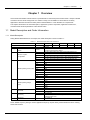
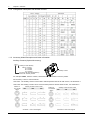
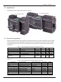
SERIES 230 B2ADTL Transfer Switch User Manual Version Revision Date BOM Code V1.6 Feb 25, 2013 31012636 Emerson Network Power provides customers with technical support. Users may contact the nearest Emerson Network Power sales office or service center. Copyright © 2012 by Emerson Network Power Co., Ltd. All rights reserved. The contents in this document are subject to change without any prior notice. Emerson Network Power Co., Ltd. Address: No.1 Kefa Rd., Science & Industry Park, Nanshan District 518057, Shenzhen China Website: www.emersonnetworkpower.com Customer Service Hotline: 4008-876-510 E-mail: [email protected] Contents Chapter 1 Overview ............................................................................................................................................................ 1 1.1 Model Description and Order Information ............................................................................................................. 1 1.1.1 Model Description ...................................................................................................................................... 1 1.1.2 Configuration Description and Number of Poles ........................................................................................ 2 1.1.3 Accessory Model Description and Order Information ................................................................................ 2 1.2 Appearance .......................................................................................................................................................... 3 1.3 Product Composition............................................................................................................................................. 3 1.4 Panel Description .................................................................................................................................................. 4 1.5 Application Environment ....................................................................................................................................... 4 1.6 Technical Parameters ........................................................................................................................................... 5 Chapter 2 Installation And Operation .................................................................................................................................. 6 2.1 Installation ............................................................................................................................................................. 7 2.1.1 Installation of Transfer Switch .................................................................................................................... 7 2.1.2 Wiring Power Terminals............................................................................................................................. 8 2.1.3 Terminal Shrouds ...................................................................................................................................... 8 2.1.4 Optional Accessory Installation .................................................................................................................. 9 2.2 Operation ............................................................................................................................................................ 15 2.2.1 Manual Operation .................................................................................................................................... 15 2.2.2 Auto Operation ........................................................................................................................................ 16 2.2.3 Padlock .................................................................................................................................................... 17 Chapter 3 Maintenance and Troubleshooting ................................................................................................................... 19 3.1 Start Up / Function Test ...................................................................................................................................... 19 3.2 Maintenance ....................................................................................................................................................... 21 3.3 Common Troubleshooting ................................................................................................................................... 21 Appendix 1 Surge Protection Device ................................................................................................................................. 22 Appendix 2 Glossary ......................................................................................................................................................... 23 Chapter 1 Overview 1 Chapter 1 Overview ASCO Series 230 B2ADTL transfer switch is a professional PC class dual power transfer switch. It adopts a reliable mechanism and an electric design built on a modular concept, and is suitable for various electric continuity applications. All Series 230 transfer switch products meet EN60947-6-1 and IEC60947-6-1 requirements. This chapter will introduce the model description, appearance, product composition, application environment , mechanical and electrical parameters of this transfer switch. 1.1 Model Description and Order Information 1.1.1 Model Description Taking B2ADTLB30160HD00 as an example, the model description is shown in Table 1-1. Table 1-1 Model Description and Order Information ① B2ADTL B3 0160 H D 0 0 ① ② ③ ④ ⑤ ⑥ ⑦ Series 230 B2ADTL transfer switch ② Number of poles, configuration ③ Rated operating current code ④ Rated operating voltage code ⑤ Controller ⑥ Accessory ⑦ Enclosure B2ADTL B1 02 B2 03 B3 0016 0020 0025 0032 0040 0050 0063 0080 0100 0125 0160 D E F H J K D E 0 X 0 Description Series 230 B2ADTL transfer switch Center-off (three-position design) 2 Poles (Sigle Phase 220V-240V, 2-Wire with Neutral Line) 2 Poles (Two Phase 220V-240V, 2-Wire without Neutral Line) 3 Poles (Two Phase 220V-240V, 3-Wire with Neutral Line) 3 Poles (Three Phase 380V-415V, 3-Wire without Neutral Line) 4 Poles (Three Phase 380V-415V, 4-Wire with Neutral Line) 16A 20A 25A 32A 40A 50A 63A 80A 100A 125A 160A 220V 230V 240V 380V 400V 415V C1000 Standard Controller C2000 Standard Controller No accessory With accessory,Such as :Auxiliary Contact 132A~132F and Bridging Busbar 132J No enclosure Notes: Default frequency setting is 50Hz.If application frequency requires 60Hz, please indicate this when ordering Series 230 Products. ASCO Series 230 B2ADTL Transfer Switch User Manual 2 Chapter 1 Overview 1.1.2 Configuration Description and Number of Poles 1.1.3 Accessory Model Description and Order Information Auxiliary Contacts (Optional Accessory) 132 A A Auxiliary Contact Quantity Blank: 1 Contact A: 2 Contacts B: 3 Contacts C: 4 Contacts Function Code (See Diagram Below) 132A-132F: Auxiliary Contact Auxiliary Contact For example: 132BA , means 2 contacts, closed when the ATS transfer to source II position. The Auxiliary Contact Code Definitions 132A-132C : The auxiliary contacts can be used to indicate positions with the CLOSE contact , see Schematic 1. 132D-132F: The auxiliary contacts can be used to indicate positions with the OPEN contact , see Schematic 2. Position of The transfer switch Auxiliary Contact Function Code Schematic 1 132A-132C Diagram Position of The transfer switch Auxiliary Contact Function Code Schematic 2 132D-132F Diagram ASCO Series 230 B2ADTL Transfer Switch User Manual Chapter 1 Overview 3 1.2 Appearance The appearance of the transfer switch is shown in Figure 1-1. Four poles transfer switch Two poles transfer switch Figure 1-1 Appearance 1.3 Product Composition Series 230 automatic transfer switch includes one transfer switch and one controller. The B2ADTL Size has multiple ampere rating options. Series 230 B2ADTL transfer switch unit can work with either the C1000 or C2000 controller. The following accessories are included as standard in the Series 230 B2ADTL automatic transfer switch package, see Table 1-2: Table 1-2 Series 230 B2ADTL Transfer Switch Standard Accessories Accessories Name Terminal Shrouds (two poles) Terminal Shrouds (four poles) Handle Connection Cable Fuse User Manual Model and Specification LDZ1F0160/2 LDZ1F0160/4 LHS2F Power Cable & Signal Cable 0215.500MXP/UDA.500 Series 230 B2ADTL Transfer Switch User Manual Part Number 63201585 63201502 21501781 04119032 19040344 2-Pole 4 pcs 1 pcs 1 set 2 pcs 3-Pole 4 pcs 1 pcs 1 set 2 pcs 4-Pole 4 pcs 1 pcs 1 set 2 pcs 31012636 1 copy 1 copy 1 copy The following accessories are included as optional in the Series 230 B2ADTL automatic transfer switch package, see Table 1-3: Table 1-3 Series 230 B2ADTL Transfer Switch Optional Accessories Function Code 132JA 132JB 132JC 132A,132AA,132AB,132AC 132B,132BA,132BB,132BC 132C,132CA,132CB,132CC 132D,132DA,132DB,132DC 132E,132EA,132EB,132EC 132F,132FA,132FB,132FC Accessories Name Bridging Busbar (two poles) Bridging Busbar (three poles) Bridging Busbar (four poles) Auxiliary Contact (NO) Auxiliary Contact (NO) Auxiliary Contact (NC) Auxiliary Contact (NC) Auxiliary Contact (NC) Auxiliary Contact (NO) Model and Specification LBS1F0160/2 LBS1F0160/3 LBS1F0160/4 LAP1F10 LAP1F10 LAP1F01 LAP1F01 LAP1F01 LAP1F10 Note: The optional accessories are an additional order item. ASCO Series 230 B2ADTL Transfer Switch User Manual Part Number 02356097 02357091 02355942 16021426 16021426 16021427 16021427 16021427 16021426 Quantity 1 1 1 1,2,3,or 4 1,2,3,or 4 2,4,6,or 8 1,2,3,or 4 1,2,3,or 4 2,4,6,or 8 4 Chapter 1 Overview 1.4 Panel Description For the transfer Switch panel description, see Figure 1-2. Source I Line Side Handle Source II Line Side Label Cover Auxiliary Contact Side Plate Arc Chamber Load Side Terminal Shrouds DIN Rail Mounting Snaps Drive Box Load Side Nameplate Position Indicator Window Label Manual Operation Hole AUTO / MANUAL / LOCK Indication Position Mark Pad Lock Pull Tab Figure 1-2 Panel Description 1.5 Application Environment Altitude: 2000 meter or less Temperature: -5°C to +40°C Humidity: Within 95%, No condensation Degrees of protection: IP20 Pollution Class: Class III Mounting Method: Horizontal or Vertical Product Standards Met: EN60947-6-1 and IEC60947-6-1 Environmental Standards Met: RoHS and WEEE ASCO Series 230 B2ADTL Transfer Switch User Manual Chapter 1 Overview 1.6 Technical Parameters For the technical parameters, see Table1-4. Table 1-4 Technical Parameters Item Rated Operating Voltage Ue (Vac) Parameter 220 / 230 / 240(2 poles) 380 / 400 / 415(3 poles / 4 poles) Ue=220 / 230 / 240 / 380 / 400 (0.7~1.2)× Ue Ue= 415 (0.7~1.15)× Ue Operating Voltage Range (V) Utilization Category AC-33B Rated Insulation Voltage Ui (V) 800 Rated Impulse Withstand Voltage Uimp (kV) 8 Rated Short-time Making Capacity Icm (peak) (kA) 17 Rated Short-circuit Withstand Current Icw (kA/0.1s) 10 Rated Conditional Short-circuit Current Iq (rms) (kA) 65 Operating Transfer Time (s) <3.5 ASCO Series 230 B2ADTL Transfer Switch User Manual 5 6 Chapter 2 Installation And Operation Chapter 2 Installation And Operation ! DANGER DANGER is used in this manual to warn of a hazard situation which, if not avoided, will result in death or serious injury. ! WARNING WARNING is used in this manual to warn of a hazardous situation which, if not avoided, could result death or serious injury. ! CAUTION CAUTION is used in this manual to warn of a hazardous situation which, if not avoided, could result in minor or moderate injury. NOTICE NOTICE is used in this manual to comments or suggestion of a fault situation which, if not avoided, could result in fault. An experienced licensed electrician must install the ATS. Each automatic transfer switch contains a rating label (Name plate) to define the loads (Ampere rating). Refer to the label on the transfer switch for specific values. ! DANGER Do not exceed the values on the rating label. Exceeding the rating can cause personal injury or serious equipment damage. ASCO Series 230 B2ADTL Transfer Switch User Manual Chapter 2 Installation And Operation 7 2.1 Installation 1. Connect with the controller See the corresponding controller user manual for controller installation details. 2. Connect Surge Protection Device The Automatic transfer switch is connected to an electronic circuit with a power supply, that is vulnerable to overvoltage damage, therefore, it is recommended that users install Class C Surge Protection Devices when using automatic transfer switches, and the right wiring methods. See Appendix 1 (Surge Protection Device) for additional details and recommended wiring methods. 2.1.1 Installation of Transfer Switch The B2ADTL transfer switch dimensions are shown in Figure 2-1. It must be installed in DIN35 Rail to the cabinet. First pull out the DIN35 Rail Mounting Snaps of transfer switch, Assemble transfer switch to DIN35 rail and then push the DIN35 Rail Mounting Snaps into place. The transfer switch has 3 DIN35 Rail Mounting Snaps. 151 105 78 slot 126 36 27 27 27 141.4 A 27 27 27 DIN35 Rail Mounting Snaps Pull out before mounting Push back in after mounting Figure 2-1 Mounting Dimensions (unit: mm) Product appearance (4 poles) with Terminal Shrouds and Bridging Busbar shown in Figure 2-2. A 110 112.5 110 29 185 126 58 ASCO Series 230 B2ADTL Transfer Switch User Manual 8 Chapter 2 Installation And Operation Bridging BusBar Optional Terminal Shrouds ) Figure 2-2 Mounting Dimension with accessories(unit:mm) Dimensions of A in Figure 2-1 and Figure 2-2 is shown in Table 2-1. Table 2-1 A Dimensions 2 Pole 241 A (mm) 3 Pole 349 4 Pole 349 2.1.2 Wiring Power Terminals 1. Remove the label cover and terminal shrouds. 2. Loosen the screw of wire plate using Hex Tool Allen 4. 3. Insert the end of the cable wire into power terminal using a six-sided Hex-Key Tool rotating clockwise, as shown in 2 Figure 2-3.The cross sectional area of the cable wire used to connect the transfer switch should not exceed 70mm . Tighten in clockwise direction Hex Tool Allen Size4 97.3lb-in / 11Nm 20mm/0.79" 2 2.5 to 70mm #13 to #00 AWG Figure 2-3 Wiring ! WARNING 1. 2. 3. The transfer switch inlet and outlet shall be properly connected. If a power is emergency power such as a generator or a battery, emergency power supply should be connected to the Source II. Cable ends bare wire length of 20±2mm,cannot be too long or too short. It is essential to tighten all the power terminals using screw torque M8:11Nm. 2.1.3 Terminal Shrouds The terminal shrouds are used to isolate and insulate the poles and ensure electrical safety. The installation procedures are as follows: 1. After wiring, insert the terminal shrouds in the slots between arc chambers from top to bottom. Make sure the terminal shroud hook slides all the way down to the bottom of the arc chamber beam. See inset drawing on Figure 2-4. ASCO Series 230 B2ADTL Transfer Switch User Manual Chapter 2 Installation And Operation Terminal Shroud Terminal Shroud Hook Insert Termina Shroud along the slot Beam on bottom of arc chamber slot Figure 2-4 Mounting Terminal Shrouds 2. When finished, snap each label cover back into its original position. Make sure that the correct label (LINE versus LOAD) is showing on the correct side. See Figure2-5. CLINEL3 NLINEN ALOADL1 BLOADL2 CLOADL3 NLOADN ALINEL1 BLINEL2 ALINEL1 BLINEL2 CLINEL3 NLINEN ALOADL1 BLOADL2 CLOADL3 NLOADN Figure 2-5 Label Cover Position Description ! CAUTION Make sure that the correct label (LINE versus LOAD) is showing on the correct side .See Figure 2-5. 2.1.4 Optional Accessory Installation Bridging Busbar (Optional Accessory) It is used to connect the switch I and II load side terminals together. ASCO Series 230 B2ADTL Transfer Switch User Manual 9 10 Chapter 2 Installation And Operation Source I Load Terminal Hex Tool Arc Chamber Bridging Busbar Source II Load Terminal Figure 2-6 Installation of Bridging Busbar The installation procedures are as follows: 1. Identify the transfer switch load side terminals. 2. As shown in Figure 2-6, first remove the label cover and terminal shrouds, then insert the bridging busbar between the Source I load side terminal and the Source II load side terminal. In order to install the bridging busbar, one might need to loosen each wiring plate (seeing Figure 2-7) in the power terminal using the Hex Tool. Because there is a spring inside each power terminal, one will need push the wiring plate down (using a screw driver or Hex Tool) to expose an opening to insert the bridging busbar into the slot insert (see Figure 2-8). This will need to be done one power terminal at a time, starting from far left or far right power terminal. When all eight Bridging Busbar terminals are inserted, then tighten each wiring plate in each Power Terminal 11Nm. Shown in Figure 2-6 and Figure 2-7, the bridging busbar is inserted between the static contact and power terminal. Bridging Bar Wiring Plate Static Contact Copper plate Power Terminal Arc Chamber Figure 2-7 Side View Bridging Busbar Detail When push the wire plate down, an opening occurs to insert the bridging busrbar into it Figure 2-8 The View Bridging Busbar inserted ASCO Series 230 B2ADTL Transfer Switch User Manual Chapter 2 Installation And Operation ! WARNING 1. The bridge busbar can only be used for the LOAD SIDE of the switch. 2. Recommended torque to be used for tightening the wiring plate : M8: 11N·m. 3.When transfer switch uses a bridging busbar, must first install bridging busbar and cable wire, and then install terminal shrouds and label cover. Terminal Shrouds (when load side is installed with bridging busbar) When load side is to be installed using a bridging busbar, the terminal shrouds must be installed as follows: 1. The terminal shrouds have knock-out blocks. When using the bridging busbar, need to remove knock-out blocks, as shown in Figure 2-9. Will need to use Industrial Grade Scissors to cut off along the edge to remove knock-out blocks. May need to clean edge with a knife. Figure 2-9 Terminal Shrouds 2. After finished installing bridging busbar and cable wiring, install terminal shrouds as indicated in chapter 2.1.3. Auxiliary Contacts (Optional Accessory) There are many different optional auxiliary contact configurations available for the B2ADTL TS unit, See the Figure 2-10 below for what options exists. ASCO Series 230 B2ADTL Transfer Switch User Manual 11 12 Chapter 2 Installation And Operation 132AA 132A Location I Location II Location I x1 132B Location I Location II 132E 132BB Location II Location I x2 x1 x1 x2 132CB Location II Location I Location II 132CC Location II Location I x2 x1 Location I Location II x2 x2 132DB Location II 132DC Location II Location I Location II x1 x1 x2 x1 x2 x2 132EB Location II Location I 132EC Location II Location I Location II x1 x1 x2 x1 x2 x2 132FA 132F Location II x2 Location I x1 132BC Location II Location I x1 132EA Location II x1 x2 Location I x1 LocationI x1 132DA Location II Location I x1 x1 x1 132D Location II x2 Location I x1 Location I x2 132CA 132C 132AC Location II x1 Location I x1 Location I Location I 132BA Location II LocationI 132AB Location II Location I 132FB Location II Location I x1 x1 132FC Location II Location I x1 x2 Figure 2-10 Auxiliary Contact Order Code and Installation The Auxiliary Contact Location as shown in Figure 2-11. ASCO Series 230 B2ADTL Transfer Switch User Manual Location II x2 x2 Chapter 2 Installation And Operation 13 Location I Auxiliary Contact Mounting Location II Auxiliary Contact Mounting Figure 2-11 Auxiliary Contact Location Definition The installation procedures are as follows: 1. With the auxiliary contact screw holes facing outward, snap the 4 claws into the corresponding 4 square holes on the transfer switch side plate, and then force it into position, as shown in Figure 2-12. (Pay special attention to the direction of the screw hole faces below) Screw hole face upward Screw hole face downward Figure 2-12 Auxiliary Contact Installation to Side Plate 2. When mounting an additional auxiliary contact on top of another contact, remove the sticker located in the center of the contact that is being mounted, then like before, with the screw holes facing outward, snap the 4 claws into the corresponding 4 square holes on the previously installed auxiliary contact and then force it into position, as shown in Figure 2-13. If installing an additional auxiliary contact on top of another, need to remove sticker on the base auxiliary contact, otherwise do not remove sticker to protect auxiliary contact from dust debris. ASCO Series 230 B2ADTL Transfer Switch User Manual 14 Chapter 2 Installation And Operation Square Hole Remove the sticker Do not remove sticker Figure 2-13 Auxiliary Contact Installation on Top of Another Contact NOTICE 1. The center sticker on the auxiliary contact that is in direct contact with the side plate must be removed before installation of the additional auxilary contact on top of it. 2. Keep the center sticker on the outer most auxiliary contact in place to avoid any debris or dust from getting inside. 3. The maximum auxiliary contacts that can be used on each side plate are 4 contacts, or 2 contacts per slot location. There are 4 total slot locations, 2 per side plate. 3. Next, insert the cable clamps into the small round holes on the transfer switch side plate. See figure 2-14. There should be 2 clamps packaged together with each optional auxiliary contact. Figure 2-14 Cable Clamp 4. After wiring the auxiliary contacts, affix the corresponding cable with the closest cable clamp using a cable tie to facilitate and optimize the wiring layout as shown in Figure 2-15. Insert Cable Clamp Figure 2-15 Schematic Diagram for Cable Routing ASCO Series 230 B2ADTL Transfer Switch User Manual Chapter 2 Installation And Operation 15 5. Auxiliary Contact Specifications: a) Ratings: Rated thermal current Ith /A Rated insulation voltage V Rated impulse withstand voltage Uimp/kV Degree of protection Pollution Class Maximum cable cross section 16 690 4 IP20 3 2.5mm2 b) Additional Information: Ue / V 230 400 690 AC-15 Ie / A 6 4 2 DC-12 Ue / V 24 72 125 250 Ie / A 10 4 2 0.55 DC-13 P/W 240 288 250 138 Ie / A 2 0.8 0.55 0.27 P/W 48 58 69 68 ! CAUTION In order to obtain higher reliability, the auxiliary contact circuit should meet the requirments: Current≥5mA 2.2 Operation 2.2.1 Manual Operation The procedures are as follows: 1. Turn the AUTO/MANUAL /LOCK to ‘MANUAL’ position, as shown in Figure 2-16. AUTO/MANUAL/LOCK switch AU TO MANUA L LO CK Indication Position Mark Figure 2-16 Switching the AUTO/MANUAL/LOCK to MANUAL ! CAUTION Make sure AUTO/MANUAL/LOCK SWITCH lines up with the correct indication position mark 2. Insert the operating handle into the handle hole, and rotate the handle according to the position and direction shown in the position indicator widow. The handle must be fully inserted into hole, or switch will not operate correctly. 1) When the window initially displays ‘OFF’ (Center-off Position), do the following operations as needed: ASCO Series 230 B2ADTL Transfer Switch User Manual 16 Chapter 2 Installation And Operation If you need to switch to Position I (Normal Source), rotate the handle 90 degrees counter-clockwise. After hearing a ‘click', and the window displays ‘I’, it indicates that the position has been successfully switched to Position I. If you need to switch to Position II (Emergency Source), rotate the handle 90 degrees clockwise. After hearing a ‘click', and the window displays ‘II’, it indicates that the position has successfully switched to Position II. 2) When the window initially displays ‘I’ (Normal Source), do the following operations as needed: If you need to switch it to the Position OFF (Center-Off Position), rotate the handle 90 degrees clockwise. After hearing a 'click', and the window displays ‘OFF’, it indicates that the position has successfully switched to Position OFF. If you need to switch it to Position II (Emergency Source), rotate the handle 180 degrees clockwise. After hearing a 'click’, and the window displays ‘II’, it indicates that the position has successfully switched to Position II. 3) When the window initially displays ‘II’ (Emergency Source), do the following operations as needed: If you need to switch it to the OFF Position (Center-off Position), rotate the handle 90 degrees counter-clockwise. After hearing a 'click', and the window displays ‘OFF’, it indicates that the position has successfully switched to the Position OFF. If you need to switch it to Position I (Normal Source), rotate the handle 180 degrees counter-clockwise. After hearing a 'click', and the window displays ‘I’, it indicates that the position has successfully switched to Position I. The detailed handle rotation positions are shown in Figure 2-17. AU T AU TO A UT O M AN UA L MA NUAL C LO K O MA NUAL C LO K C LO I (Normal source) OFF (Center-off-Position) If Initial Position is Position OFF If Initial Position is Position OFF II (Emergency Source) If Initial Position is Position OFF Figure 2-17 Switch Rotation Diagram ! CAUTION 1. 2. 3. 4. If the AUTO/MANUAL/LOCK switch is not in the right position (MANUAL), the handle cannot be inserted. If the handle is not inserted into the handle hole,the handle will not operate. The manual handle operation torque should more than 5Nm. Due to high torque of the handle during operation, the operator should be careful to avoid from getting injured from touching the AUTO/MANUAL/LOCK switch and padlock pull tab objects. 2.2.2 Auto Operation 1. Remove the operating handle from the handle hole. 2. Turn the AUTO/MANUAL/LOCK switch to ‘AUTO’ Position, as shown in Figure 2-18. ASCO Series 230 B2ADTL Transfer Switch User Manual Chapter 2 Installation And Operation 17 AUTO/MANUAL/LOCK Switch Indication Position Mark AU TO MA NUA L LO CK Figure 2-18 Switching AUTO/MANUAL/LOCK to AUTO ! CAUTION Make sure AUTO/MANUAL/LOCK switch lines up with the correct indication position mark 3. Once AUTO/MANUAL/LOCK switch is in the 'AUTO' Position, the switch will automatically transfer to the position that is currently set in the controller. (For a description of how to set the positions in the controller, refer to the Series 230 C1000 Controller User Manual or Series 230 C2000 Controller User Manual). ! WARNING 1.If the handle has not been removed, the AUTO/MANUAL/LOCK switch cannot be switched to the 'AUTO' Position. 2.After the manual operation, the operator must ensure that the AUTO/MANUAL/LOCK switch moves back to the 'AUTO' Position, and the Auto/Manual/Lock switch lines up with the 'AUTO' Position indicator mark. Otherwise, the transfer switch will not work in Automatic Mode. 2.2.3 Padlock In order for the Padlock Pull Tab to function properly, one must ensure that the switch is in Manual Mode AND the handle is in the Position OFF. To do this, do the following in this order: 1. Ensure that the AUTO/MANUAL/LOCK switch is in ‘LOCK’ position as shown in Figure 2-19. AUTO/MANUAL/LOCK Switch AU TO MA NUA L LO CK Indication Position Mark Figure 2-19 Switching AUTO/MANUAL/LOCK to LOCK ! CAUTION 1. If the transfer switch is not in OFF position,the AUTO/MANUAL/LOCK switch can’t be turned to ‘LOCK’ position. 2. If the AUTO/MANUAL/LOCK switch is not in LOCK position, the padlock pull-tab cannot be pulled up. 2. Pull the padlock pull-tab out and lift up to expose the lock hole. lock it. As shown in Figure 2-20. Then insert the proper padlock into the hole to ASCO Series 230 B2ADTL Transfer Switch User Manual 18 Chapter 2 Installation And Operation Figure 2-20 Padlock lift up ! CAUTION The specified diameter of the B2ADTL transfer switch padlock must be φ3mm to φ4mm. ASCO Series 230 B2ADTL Transfer Switch User Manual Chapter 3 Maintenance and Troubleshooting 19 Chapter 3 Maintenance and Troubleshooting This chapter describes the transfer switch installation, commissioning and common faults and maintenance methods. 3.1 Start Up / Function Test 1. To Test Manual Operation Two power supply Sources must be disconnected before manual testing can begin. Refer to chapter 2.2.1 to run Manual Operation mode. Operate the transfer switch from I position to II position and turn back to I position with handle. The operation should be smooth, without interruption. If so, switch is operating correctly in manual mode. 2. To Verify Voltage Detection First make sure the rated voltage of the transfer switch on the nameplate is the same as the dual-power supply rated voltages. Next, review the C2000 or the C1000 controller, to make sure the power is being supplied to transfer switch. Source I and Source II Auxiliary Indication LED lights are on (green), This should indicate your wiring is correct. If using the C2000 controller, Double-check and measure the dual-supply voltage, to make sure voltages are consistent to what is indicated on the C2000 controller . ! DANGER When measuring Voltage, pay attention to not touch the terminals and copper bars, otherwise it could result in death, or serious injury. 3. To Test Electric Operation This is used to test the controller in electric operation mode and operate the transfer switch electrically. Using C2000 controller: Menu Setting 2. Settings Control Up Menu Down Scrolling the main menu to “Setting” ,and press “Enter” button. Control Mode Scrolling the Setting menu to “Control Mode” ,and press “Enter” button. The Control Mode Menu will display the last settings.for example,the default control mode is S1 Prior. Control Mode Scrolling the Control Mode menu to “Manual Control” ,and press “Enter” button.and then setting is ok,system will be reset. Must press the “Enter” button when the Control Mode is setted,the contorller will be reset to complete the set. Control Mode S1 Prior Up Down Description Settings Enter 2.4 Operation Enter 2.4 Control Mode Manual Control Up Down Enter ASCO Series 230 B2ADTL Transfer Switch User Manual 20 Chapter 3 Maintenance and Troubleshooting Once you, successfully set up the manual control mode, the “Auto” LED on the controller panel will blink. (1) Electric Operation Test The transfer switch can now transfer and return. The operation should be smooth. Description of the operation is as follows. 7. Manu Control Manu Action Down Up Menu Manu Control Scrolling the main menu to “Manu Control” ,and press “Enter” button. Switch Ctrl Next,Scrolling the menu to “Switch Control” ,and press “Enter” button. Enter 7.1 Switch Ctrl Action Operation Description Down Up Enter 7.1 Switch Ctrl X->II Up Switch Ctrl Then Scrolling the menu to the target location,such as the transfer switch is in location I,scrolling the menu to “X→II” and press “Enter” button,the switch should be transferred to Location II. Down Enter Operate the switch again,it can be tansferred to Location I,Location OFF or Location II.If the switch is in Location I,scrolling the menu to “X→ I” and press Enter,the switch will not tranfer. (2) Return To The Original Control Mode After completing the electric operation test, you can return to the original control mode by using the menu settings. Using C1000 Controller: (1) According to The 230 Series Automatic Transfer Switch C1000 Intelligent Controller User Manual, the DIP 7-8 is set to ON, ON, the run LED will blink, and one of the switch’s Position Indication LED’s will blink, The controller is now in manual control mode. (2) The blinking LED is the target position that the switch will transfer to. Press the key less than 3 seconds, the position indication LED will blink alternately to show which position is target transfer. Choose a transfer target position. (3) Press the key 3 Sec, and the switch will transfer to the target position. (4) The switch can transfer and return by this method, and the operation should be smooth. (5) According to The 230 Series Automatic Transfer Switch C1000 Intelligent Controller User Manual, the DIP 7-8 is set to automatic or remote Mode, and the controller will exit manual control mode. ASCO Series 230 B2ADTL Transfer Switch User Manual Chapter 3 Maintenance and Troubleshooting 21 3.2 Maintenance To ensure consistent reliability of the transfer switch to make sure it is operating normally, regular maintenance testing should be conducted. It is recommended to do so once every three months. 3.3 Common Troubleshooting Table 3-1 Troubleshooting Guideline Troubleshooting Issues No response in auto mode The handle cannot be inserted in order to operate the switch manually. Once handle is inserted, one cannot operate the handle The AUTO/MANUAL/LOCK switch cannot be set to 'AUTO' Position The padlock pull-tab cannot be pulled up Recommended Action ·Check if the AUTO/MANUAL/LOCK switch is in 'AUTO' Position. ·Check if the wiring is routed correctly ·Check if the power supply meets the rated voltage range. ·Check if the fuse is properly installed and /or destroyed ·Check if the AUTO/MANUAL/LOCK switch is in 'MANUAL' Position ·Check if the transfer switch has been locked. ·Check if the handle is turning in the correct direction based on Chapter 2.2.1. ·Check if operator is applying enough force to handle (recommend operating torque is greater than5N·m but less than 16 N·m) ·Check to make sure the handle has been removed from the handle hole. ·Check to make sure the padlock pull-tab has been pushed all the way down to the original unlocked position. ·Check if ‘OFF’ is displayed in the position indicator window. ·Check to make sure the AUTO/MANUAL/LOCK switch is in 'LOCK' Position For all other issues, please contact Emerson Network Power. Check and Replace Fuse: 1. Before checking the condition of the fuse, the operator MUST switch the AUTO/MANUAL/LOCK switch to the 'MANUAL' Position. 2. Then, the operator can open the fuse housing cover, take out the fuse, and check the fuse resistance by ohmmeter or multi-meter to determine if fuse is blown out or not. 3. If fuse is blown out (damaged), then replace it using an equivalent rated fuse. 1-2. Finally, close the fuse housing cover. For more information, go to Table 4. After new fuse has been replaced, and if the operator wants to use Auto Mode, then switch the AUTO/MANUAL/LOCK switch back to the 'AUTO' Position. ! DANGER 1. Only a professional electrician should operate to check and replace the the fuse. Such a person MUST be equiped with insulated rubber boots, insulated gloves, and insulated tools. 2. Before removing the damaged fuse, the operator MUST switch the AUTO/MANUAL/LOCK switch to the 'MANUAL' Position. ASCO Series 230 B2ADTL Transfer Switch User Manual 22 Appendix 1 Appendix 1 Surge Protection Device 1. In order to run the Automatic Transfer Switch reliably, SPD’s are needed before connecting the Automatic Transfer Switch to Source I and Source II. It is recommended that the SPD wire connections use V shape wiring method shown in Appended Figure 1. When limited by practical conditions, and if it is difficult to adopt V shape wiring, one can also use routine direct-parallel-connection method shown in Appended Figure 2. The connection wire should be as short as possible (less than 0.5m) when using direct-parallel-connection method to achieve better protective performance. 2 2. The connection wires should be multi-core copper wire with a cross-sectional area greater than 10mm (AWG6). 3. Appropriate MCB or Fuse should be serial-connected to the front-end of the SPD for AC power supply. The MCB should have the ”C” tripping characteristic. 4. The power supply should be cut off when installing SPD’s. Live installation is prohibited. All the wires must be connected properly, and using correct wires. 5. While the SPD does not need special maintenance, it is recommended that one periodically checks whether the indicators of the SPD are functioning normally and to make sure the modules are not loose. 6. If either of the following situations appear, the SPD has failed and needs to be replaced. 1) The SPD indicator turns red. 2) The SPD remote signal contact becomes an open-circuit. 7. The Wiring method show in Appended Figure 3 is forbidden. If SPD is wired similar to Appended Figure 3, the wiring needs to be modified to Appended Figure 1 or Appended Figure 2. Connection Wiring Lenth≥1m L1 Source L2 I L3 N Series230 Transfer Switch Source I Load Connection Wiring Lenth≥1m MCB or Fuse MCB or Fuse Controller Grouding Cable Lenth ≤ 0.2m Cable line ≤ 2m Appended Figure 1: V Shape Wiring Method Connection Wiring Lenth≥1m L1 N Surge Protection Device Wiring from Main Circuit to Grand lenth ≤ 0 . 5 m MCB or Fuse Load Class C Surge Protection Device Connection Wiring Lenth≥1m L1 N MCB or Fuse Surge Protection Device Wiring from Main Circuit to Grand lenth≤0.5m Grouding Cable Lenth ≤ 0.2 m Cable Line ≤ 2m Appended Figure 2: Direct-Parallel-Connection Method Series230 Transfer Switch Surge Protection Device Wiring from Main Circuit to Grand lenth ≤0.5m Source L2 II L3 Controller Class C Surge Protection Device Class C Surge Protection Device Source L2 I L3 Connection Wiring Lenth ≥ 1 m L1 L2 Source L3 II N N Surge Protection Device Wiring from Main Circuit to Grand lenth≤0.5m Load Surge Protection Device Wiring from Main Circuit to Grand lenth ≤ 0 . 5 m Class C Surge Protection Device Class C Surge Protection Device L1 Series230 Transfer Switch MCB or Fuse MCB or Fuse Surge Protection Device Wiring from Main Circuit to Grand lenth≤0.5m Source L2 II L3 Connection Wiring Lenth ≥ 1 m L1 L2 L3 N Controller Grouding Cable Lenth ≤ 0.2m Cable Line ≤ 2m Class C Surge Protection Device Appended Figure 3: Wrong Connection Method ASCO Series 230 B2ADTL Transfer Switch User Manual Appendix 2 Appendix 2 Glossary ATS NC NO Automatic Transfer Switch Normally Closed Normally Open ASCO Series 230 B2ADTL Transfer Switch User Manual 23