1
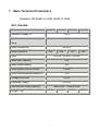
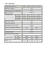
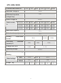
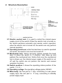
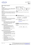
GuiLin GuangMing Technology Industry Ltd.
AT S
User Manual
Address: No.16 YiFeng South Road, Guilin, GuangXi, China
Post Code: 541004
Tel: +86 0773 5803731, +86 0773 5850657
Fax : +86 0773 5814532
E-mail:[email protected]
http://www.chinagmti.com
1. Main Technical Parameters
Standard: IEC60947-6-1/GB 14048.11-2002
ATS: 20A-80A
Promise heat current Ith
20A
40A
Insulation voltage Ui
Withstand
impulsion
63A
80A
750V
voltage
8KV
Uimp
Rated voltage Ue
Rated current Ie
AV440V
20A
Load
40A
63A
AC31A、AC35A、AC33A
Make-open capacity
10Ie
Make-break capacity
8Ie
Limiting short-circuit current
100KA
Short-time withstand capacity IS
7KA
Change-over time
0.45S
Operating voltage
AC220V
Electromotor energy wasting
Weight(kg)
80A
Start 300W、Normal 55W
4.2
1
4.3
4.4
4.5
ATS: 100A-250A
Promise heat current Ith
100A
125A
160A
Insulation voltage Ui
750V
Withstand impulsion voltage Uimp
8KV
AC440V
Rated voltage Ue
Rated current Ie
250A
AC-31A
100
125
160
250
AC-35A
100
125
160
250
AC-33A
100
125
160
250
Make-open capacity
10Ie
Make-break capacity
8Ie
Limiting short-circuit current
100KA
Short-time withstand capacity IS
7KA
9KA
Change-over time
0.45S
Operating voltage
AC220V
Electromotor energy wasting
start
300W
325W
natural
55W
62W
Rated voltage
Weight(kg)
7.5
2
7.5
8.8
9
ATS: 400A-1600A
Promise heat current Ith
400A
630A
800A
1000A
Insulation voltage Ui
1000V
Withstand impulsion
12KV
1250A
1600A
voltage Uimp
AC440V
Rated voltage Ue
Rated current
Ie
AC-31A
400
630
800
1000
1250
1600
AC-35A
400
630
800
1000
1250
1600
AC-33A
400
630
800
1000
1250
1600
Make-open capacity
10Ie
Make-break capacity
8Ie
Limiting
short-circuit
70KA
current
Short-time
100KA
withstand
13KA
capacity IS
Change-over time
26KA
50KA
0.6S
1.2S
Operating voltage
Electromotor
120KA
AC220V
energy
wasting
start
355W
400W
440W
natural
74W
90W
98W
Rated voltage
Weight(kg)
16.5
17
3
32
36
40
43
2. Structure Description
2.1 Electric control lock: It is used to control the internal power
supply circuit of the switch. When the electric lock is turned on,
the switch performs automatic and remote control operation;
when the electric lock is turned off, the switch can only perform
manual operation.
2.2 Operating hand lever: while the hand lever is used to operated
the switch, the electric lock must be turned off. ※
2.3 Mechanical lock: before servicing, please operate the hand
lever to place the switch to ‘0’ position, then draw up and
padlock the mechanical lock. Notice that once the mechanical
lock is drawn up, the internal power supply of the switch is cut
off and the switch can not perform the electric and manual
operation functions.
2.4 Switch position: it shows the operating status position of the
switch(I, 0, II).
2.5 Operating voltage: the operating voltage grade, 220VAC.
2.6 Main body: the fore part is ‘I’ way, connecting to main power
supply input; the rear part is ‘II’ way, connecting to standby
power supply input.
4
3. Fixing Dimensions
Hand lever
Size
mm
20A~
80A
100A
125A,160A
250A
400A
630A
800A
1000A
1250A
1600A
A
244.5
303
359
433
633
633
633
B
106
135.5
160
260
330
330
330
B1
106
135
135
228
250
250
250
C
160
251
251
319
370
370
370
E
133
195
195
262
321
321
321
G
145
190
190
190
470
470
470
J
227.5
280
339
415
611
611
611
K
84
95/110
95
180
220
220
220
L
7
7
7
9
11
11
11
N
74.5
86
86
89
85
85
85
O
153
194
253
324
524
524
524
P
30
36
50
65
120
120
120
R
14
20
25
40
63
63
80
T
2.5
3.5
3.0
5
7
7
15
V
10.5
20
27
37.5
60.5
60.5
60.5
W
126
152
162
180.5
188.5
188.5
188.5
X
6
9
11
13
Y
36
58
60.5
82.5
107
111
111
Y1
86
136.5
136.5
192.5
249
249
253
5
4. Operating Method
4.1 The wiring connection method for main switch
Attention to the sequence of the wiring.
4.2 Typical wiring connection method
※ HL1 is used for the indication of main power supply and HL2 is
for standby power supply.
HD1、HD2 are used to indicate the main power supply or
standby power supply is launched.
FU1、FU2、FU3 are 2A fuses.
6
※ SB1 is a manual button for launching the main power supply
(passive contactor).
SB2 is a manual button for launching the standby power supply
(passive contactor).
SB3 is a button pressed to set the switch to ‘0’ way
(passive contactor, self-lock).
4.3 Fixing method
(A)(B)(C)are correct.
(D)is wrong.
7