1
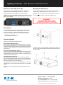
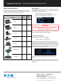
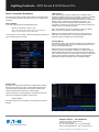
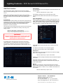
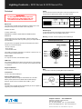
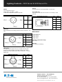
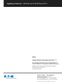
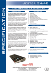
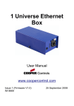
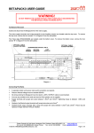
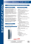
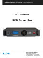
Lighting Controls – SCD Server & SCD Server Pro SCD Server SCD Server Pro Cooper Controls – Zero 88 Series Usk House, Lakeside, Llantarnam Park, Cwmbran, NP44 3HD. UK Tel: +44 (0)1633 838088 Fax: +44 (0)1633 867880 Email: [email protected] Web: www.zero88.com SCD Server & SCD Server Pro – 9850-000387-01 - Page 1 of 8 Lighting Controls – SCD Server & SCD Server Pro SCD Server and SCD Server Pro Mounting the SCD Server The SCD Server is a 2U high DMX generator, running the ZerOS Operating System and emulating an iCAN Source Controller The SCD Server is designed to be rack mounted into a standard 19” cabinet using 4 x M6 Cage Nuts and 4 x M6 x 16mm screws. Designed to be used in both entertainment and architectural situations, the SCD Server is able to backup ZerOS consoles, or work stand-alone, triggering entertainment style lighting via an architectural lighting control network. Ventilation must be provided in the rack such that the SCD Server can freely draw air from its front and rear ventilation slots. WARNING! INSUFFICIENT AIRFLOW WILL CAUSE OVERHEATING AND THE SCD SERVER WILL MALFUNCTION AND / OR SHUT DOWN This manual This manual describes the setup and operation of the SCD Server. An understanding of the ZerOS operating system from Zero 88, and/or iLight networks is assumed. For detailed instructions into these please visit their respective websites for further material. - zero88.com/software/zeros - ilight.co.uk/products-software.html Operation Modes SCD Server provides three operation modes: ZerOS Tracking Backup (Page 3) The SCD Server can operate as a tracking backup unit to consoles running the ZerOS Operating System. Changes made on the ZerOS console are automatically sent over a network and duplicated on the SCD Server, which will take over if communication from the master console is lost. Source Controller Emulation (Page 4) If the SCD Server is to be freestanding on a flat surface (rather than in a rack), rubber feet (included) should be attached to the bottom of the unit as shown. The ‘Source Controller Emulation’ allows DMX from the SCD Server to be controlled as ‘physical channels’ of one or more virtual source controllers. Normal source controller operations of programming and outputting scenes are supported. iCAN Desk Interface (Page 5) The ‘Desk Interface’ maps virtual Areas and Scenes to features within the ZerOS Operating System, such as cues, submasters and macros. This allows Architectural Lighting Control systems to trigger Entertainment Lighting Control style functions. The ‘Desk Interface’ and ‘Source Controller Emulation’ can be used simultaneously, using the ‘Highest Takes Precedence’ rule per DMX channel. These three modes are described in greater detail further into this manual. Cooper Controls – Zero 88 Series Usk House, Lakeside, Llantarnam Park, Cwmbran, NP44 3HD. UK Tel: +44 (0)1633 838088 Fax: +44 (0)1633 867880 Email: [email protected] Web: www.zero88.com SCD Server & SCD Server Pro – 9850-000387-01 - Page 2 of 8 Lighting Controls – SCD Server & SCD Server Pro Device Settings ZerOS Tracking Backup The SCD Server can operate as a tracking backup unit to consoles running the ZerOS Operating System. The below table shows which versions of the SCD Server support which consoles. SCD Server Console SCD Server Pro The first step of using the SCD Server as a Tracking Backup unit is to set the ‘desk type’ so the SCD Server can emulate the console you are backing up. This setting is within: SETUP > Desk Setup > System Settings (NB: To enter SETUP, either use the button on the ‘Programming’ desktop, or use the keyboard shortcut SHIFT+F10) ORB WARNING! ORB XF Solution Changing the Desk Type will run a full reset of the SCD Server – losing any data saved on the console, and requiring you to restart the device. In this screen you can also give your device a name – helpful when there are multiple consoles on the same network. Tracking Backup Settings Solution XL Tracking Backup can then be enabled within: SETUP > Network > Tracking Backup FROG 2 Leapfrog 48 Leapfrog 96 Change ‘Mode’ to ‘Backup’. SCD Server will search the network to find other ZerOS consoles waiting to be backed up. If there are more than one console on the network, choose which console to backup by selecting it from the list within ‘Master Desk’. If no consoles are found, choose ‘Manual Entry’ (in the ‘Master Desk’ drop down list) and then enter the IP address of the Master console. You can exit SETUP by clicking the cross in the top right of the screen. For more information on tracking backup, managing the network and other functionality, please refer to the manual of the console you are backing up. Cooper Controls – Zero 88 Series Usk House, Lakeside, Llantarnam Park, Cwmbran, NP44 3HD. UK Tel: +44 (0)1633 838088 Fax: +44 (0)1633 867880 Email: [email protected] Web: www.zero88.com SCD Server & SCD Server Pro – 9850-000387-01 - Page 3 of 8 Lighting Controls – SCD Server & SCD Server Pro Source Controller Emulation The ‘Source Controller Emulation’ allows DMX from the SCD Server to be controlled as ‘physical channels’ of one or more virtual source controllers. Device Settings To do this, CAN must first be enabled within setup: SETUP > Desk Setup > Inputs > CAN (NB: To enter SETUP, either use the button on the ‘Programming’ desktop, or use the keyboard shortcut SHIFT+F10) In the dropdown, choose ‘iCAN’, and then exit SETUP by clicking the cross in the top right of the screen. CAN Interface In the ‘CAN Interface’ window, virtual Source Controllers can be enabled and disabled. Each Source Controller is a group of 128 DMX channels (patched channels within ZerOS are ignored), and is labeled to reflect the universe and DMX addresses it’s controlling. By default, the four Virtual Source Controllers for Universe 1 are enabled, and all others are disabled. Only enable those Source Controllers you intend to use, as large channel counts can take long periods of time to be read into iCAN Soft. In the ‘CAN Interface’ window, the ‘Segment’, ‘Node’ and ‘Device Name’ can also be changed to suite the application. Behaviour from this point forward is as per any physical Source Controller on an iCAN network– scenes can be programmed via iCANsoft and can be triggered via iCAN messages. Intensity Mixing ZerOS fixtures, patch, and other fixture settings are not applied to the Source Controller Emulation. Source Controller Emulation only has access to direct DMX addresses. When both the Source Controller Emulation and ZerOS Desk Interface are being used together, operation is completely separate until the DMX is generated. At this point, ZerOS performs a Highest Takes Precedence (HTP) mix on the outputs. This means that a DMX channel will be outputted at whichever value is highest between ZerOS Desk Interface and CAN Source Controller Emulation. Desktop View By default, you will be presented with the ‘CAN Interface’ window across the top half of the monitor, and the ‘DMX Output’ window across the bottom half (the DMX universe being viewed can be changed using the tabs along the top of this window). If this is not the case, choose ‘Desktop 1’ in the bottom left corner, choose the ‘Programming’ desktop, and then type: VIEW 1 ENTER This will change the view on Desktop 1 to match the screenshot to the right. Cooper Controls – Zero 88 Series Usk House, Lakeside, Llantarnam Park, Cwmbran, NP44 3HD. UK Tel: +44 (0)1633 838088 Fax: +44 (0)1633 867880 Email: [email protected] Web: www.zero88.com SCD Server & SCD Server Pro – 9850-000387-01 - Page 4 of 8 Lighting Controls – SCD Server & SCD Server Pro Grand Master iCAN Desk Interface The ‘Desk Interface’ maps virtual Areas and Scenes to features within the ZerOS Operating System, such as cues, submasters and macros. The Grand Master can also be assigned a virtual Area Number. This setting is within: SETUP > Desk SETUP > Inputs > CAN. CAN must be enabled (see instructions under ‘Source Controller Emulation’) and the ‘Desk Interface’ must also be enabled, which is at the bottom of the list of Source Controllers in the ‘CAN Interface’ window. Scene Modify messages can be used to alter the current Grandmaster level (Latest Takes Precedence with the physical fader). Programming Each Cue Stack has the option of adding a CAN Virtual Area. This can be added once at least one cue has been recorded into a Cue Stack. Choose ‘Stack Setup’ (or use the syntax STACK x SETUP) and enter a number into ‘CAN Virtual Area’. Scene messages will trigger the relative cue within that stack (Scene 1 = Cue 1 etc.). When working as a Desk Interface, the SCD Server is designed to be programmed on a full console, and then have the showfile transferred onto the device either by USB or via Tracking Backup. However, direct programming and editing can be done via Mouse and Keyboard, or via a Touch Screen. Cues & Cue Stacks The first step of using the SCD Server like this is to set the ‘desk type’ so the SCD Server can emulate the console you are using. This setting is within: SETUP > Desk Setup > System Settings (NB: To enter SETUP, either use the button on the ‘Programming’ desktop, or use the keyboard shortcut SHIFT+F10) WARNING! Changing the Desk Type will run a full reset of the SCD Server – losing any data saved on the console, and requiring you to restart the device. An emulation of the front panel of the console can be found by clicking ‘Desktop 1’ in the bottom left of the screen, and choosing ‘Programming’. Whenever a key has to be held down (SHIFT for example), click (or touch) and hold shift for a few seconds to ‘lock’ it on. Select Next Scene and Get Current Scene commands are also supported. If an Alarm Set is received, Cue 132 will be triggered. If an Alarm Clear is received, Cue 1 will be triggered. Submasters Submasters can be given both Area and Scene numbers to trigger them. These settings are within: SETUP > Desk Setup > Inputs > Submasters Sending a Scene 0 message will release all the submasters assigned to that area. Submaster fade times are used when triggering a releasing submasters via the Desk Interface. These can be set by using the syntax SUB x SETUP. Macros Macros can be assigned a virtual Area Number. Macros will be triggered when receiving the relative Scene Number from within the defined Area (Scene 1 = Macro 1 etc.). The Macro Virtual Area can be set within: SETUP > Desk Setup > Inputs > CAN Cooper Controls – Zero 88 Series Usk House, Lakeside, Llantarnam Park, Cwmbran, NP44 3HD. UK Tel: +44 (0)1633 838088 Fax: +44 (0)1633 867880 Email: [email protected] Web: www.zero88.com SCD Server & SCD Server Pro – 9850-000387-01 - Page 5 of 8 Lighting Controls – SCD Server & SCD Server Pro Audio Technical The SCD Server has three audio ports on the rear panel (line in, line out and sound to light input) as stereo ¼ inch jack sockets. WARNING Audio Connector DO NOT REMOVE THE COVERS WITHOUT FIRST COMPLETELY DISCONNECTING THE SCD SERVER FROM THE MAINS SUPPLY Mains Inlet The SCD Server is fitted with an IEC60320-C14 Mains Inlet on the back panel and power on/off switch on the front panel. 90-264V AC ONLY Area Desc. Tip Left Channel Ring Right Channel Sleeve 0V Signal Ground Remote Input 47-63Hz, 200VA (2A) INTERNALLY FUSED. A GOOD EARTH CONNECTION IS ESSENTIAL An 8 pin DIN connector providing 6 remote switches (common ground). Short pin to 0v to simulate a button push. Warning – Do NOT connect anything to the undefined pin. The internal fuse is not user replaceable, contact an authorized service agent if the desk does not power up and you suspect that the fuse has failed. Pin Remote Switch 1 Switch 6 2 Switch 1 3 Switch 2 The supply cord must be protected to a maximum current of 10A. If in doubt consult a qualified electrician. 4 Switch 3 Video Output 5 Switch 4 6 Switch 5 7 Not Used 8 0V Common Ground Remote Input Connector The SCD Server is supplied with a bare ended mains lead, which should be connected as follows: - Brown: Live (Hot) - Blue: Neutral - Green/Yellow: Earth 2 x 15 pin D connector, XGA resolution output. USB Ports Four external USB ports are fitted on the SCD Server. Three located on the front panel and one on the rear panel. These support the USB 1.1 standard. Keyboard & Mouse Can be added via USB 1.1. MIDI 2 x 5 pin DIN connectors providing MIDI input and MIDI thru. Touchscreen Can be connected via USB port. MIDI Connector External Storage Devices The primary method of storage for the SCD Server is via USB Memory Sticks (also known as Flash Disks or Mass Storage Devices). These can be connected via the USB 1.1 ports. Pin In Thru 1 Not Used Not Used 2 Not Used Signal Ground Not Used Not Used 3 4 Ethernet The SCD Server is fitted with an RJ45 Ethernet port and is capable of supporting various Ethernet protocols. 5 Opto Isolated Input Opto Isolated Input Output Output Cooper Controls – Zero 88 Series Usk House, Lakeside, Llantarnam Park, Cwmbran, NP44 3HD. UK Tel: +44 (0)1633 838088 Fax: +44 (0)1633 867880 Email: [email protected] Web: www.zero88.com SCD Server & SCD Server Pro – 9850-000387-01 - Page 6 of 8 Lighting Controls – SCD Server & SCD Server Pro AV Port SMPTE The desk also has a 9 pin D-type RS232 – for future use. 3 pin XLR input and output. Output 0dBm. Input 0dBm +/- 10dBm. 47 kOhm input impedance. Maximum 50V RMS. RJ12 (CAN) Port SCD Server is fitted with an RJ12 socket for connectivity to iCAN networks. SMPTE Connector Pin Desc. 1 Signal Ground RJ12 (CAN) Connector 2 3 Output Input Pin Desc. 1 Not Used 2 +12V 3 CAN - H 4 CAN - L 5 0V 6 Not Used DMX Input 5 pin XLR isolated, with voltage protection. Data on channels 1 - 512 only. DMX Input Connector Pin Desc. 1 Signal Ground (0V) 2 DMX Drive Complement (1-) 3 DMX Drive True (1+) 4 Not Connected 5 Not Connected Mechanical - Height: 88mm (2U) - Width: 483mm - Depth: 301mm - Wight: 5.6KG Operating Temperature Range +5 to +40 °C Humidity 5% to 95% Non condensing DMX Output Two DMX universes (SCD Server) or four DMX universes (SCD Server Pro) each consisting of 5 pin XLR, isolated, with voltage protection and data output indicator. Data on channels 1 – 512 only. RDM Ready. DMX Input Connector Pin Desc. 1 Signal Ground (0V) 2 DMX Drive Complement (1-) 3 DMX Drive True (1+) 4 Not Connected 5 Not Connected Cooper Controls – Zero 88 Series Usk House, Lakeside, Llantarnam Park, Cwmbran, NP44 3HD. UK Tel: +44 (0)1633 838088 Fax: +44 (0)1633 867880 Email: [email protected] Web: www.zero88.com SCD Server & SCD Server Pro – 9850-000387-01 - Page 7 of 8 Lighting Controls – SCD Server & SCD Server Pro Notes Cooper Controls Ltd reserves the right to make changes to the equipment described in this manual without prior notice. This equipment is designed for professional stage lighting control, and is unsuitable for any other purpose. It should be used by, or under the supervision of, an appropriately qualified or trained person. E&OE. Cooper Controls Ltd reserves the right to change the specification without prior notice. © Cooper Controls Ltd Cooper Controls – Zero 88 Series Usk House, Lakeside, Llantarnam Park, Cwmbran, NP44 3HD. UK Tel: +44 (0)1633 838088 Fax: +44 (0)1633 867880 Email: [email protected] Web: www.zero88.com SCD Server & SCD Server Pro – 9850-000387-01 - Page 8 of 8