1
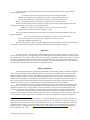
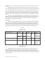
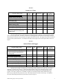
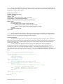
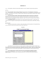
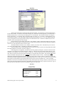
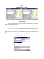
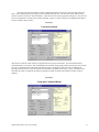
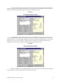
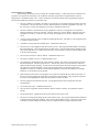
College of Business
Administration
Northern Arizona University
Box 15066
Flagstaff AZ 86011
A Design Tool for Novice
Programmers
Working Paper Series
Jo-Mae Maris
College of Business Administration
Northern Arizona University
Flagstaff, AZ 86011
(520) 523-7403; Fax (520) 523-7331
[email protected]
Craig VanLengen
College of Business Administration
Northern Arizona University
Flagstaff, AZ 86011
(520) 523-7392; Fax (520) 523-7331
[email protected]
Rick Lucy
College of Business Administration
Northern Arizona University
Flagstaff, AZ 86011
(520) 523-9185; Fax (520) 523-7331
[email protected]
00-01 — April 2000
College of Business
Administration
Northern Arizona University
Box 15066
Flagstaff AZ 86011
A Design Tool for Novice
Programmers
Jo-Mae B. Maris, Craig VanLengen and Rick Lucy
PROBLEM
Novice programming students frequently ask, “Where do I start?” How many times has the question been
asked after the teacher has presented structured-design, object-oriented design, or the universal modeling language?
Does the problem lie with the teacher or with the methods?
At least one method did not specify a starting place in its initial presentation. The method was stepwise
design:
“In each step, one or several instructions of the given program are decomposed into more detailed
instructions. This successive decomposition or refinement of specifications terminates when all instructions are
expressed in terms of an underlying computer or programming language, … “ [Wirth].
Wirth did provide more guidance in his Pascal User Manual and Report: “In the early stages, attention is
best concentrated on the global problems, and the first draft of the solution may pay little attention to the
details”[Jensen].
Most of the methods give starting points:
•
“The first step in actual class design is to find the primary objects”[Arnow].
•
“… make a model that defines the key domain classes in the system”[Erikkson].
•
“Identify the classes and objects at a given level of abstraction”[Booch].
•
“Investigate the problem domain: observe first-hand; listen actively; check previous OOA results;
check other systems; read, read, read; and prototype”[Coad].
•
“Rules for developing a proof or program:
1. Do the single option available in the simple case of only one option;
2. Choose the complex option;
3. Start on the most complicated side.
That is start with the hard job first”[Dijkstra].
•
“The first business of design is therefore to translate the specifications into the fixed formats of a set of
working documents (Data Flow Diagrams, Data Dictionary, Transform Descriptions, and Data
Structures Charts…)”[DeMarco]
The student programmer may be able to recite the definition of terms used in the preceding guidelines, but
to make use of the concepts may be beyond the level of learning programming for the student. A programmer
needs experience to grasp the hard job, level of abstraction, problem domain, and domain classes. For the novice,
all of the jobs are hard. Level of abstraction, problem domain, and domain classes are terms the novice has
memorized. Two sets of authors discussing object-oriented design recognized this problem. Rumbaugh, Blaha,
Premerlani, Eddy, and Lorensen acknowledge the problem directly:
“The content of an object model is a matter of judgment …”[Rumbaugh].
Judging is in the problem-solving level of the cognitive domain of learning [TIPS]. “The knowledge level
forms the base upon which the application level is built, and the application level forms the base for the problemsolving level”[TIPS, p.34]. Hence, beginning students, who are still memorizing terms, are in the knowledge level
that includes “define, recite, repeat, and restate” among its activities [TIPS, p.46].
CBA Working Paper 00-01 April 2000
2
Coad and Yourdon recognized the problem indirectly by pointing out that through experience objects
become readily apparent:
“As analysts experienced in applying OOA across widely divergent problem
domains, we recognize certain patterns across systems. And so at times it might seem
that the Class-&-Objects are ‘just there for the picking’” [Coad and Yourdon, p.52].
However, student programmers would not have the experience of Coad and Yourdon.
Another recognition of the need for experience to design programs using existing methods comes from
DeMarco in the chapter titled “Transition into the Design Phase”:
“When you’re done with this chapter you won’t know how to do a Structured
Design, unless you knew that already” [DeMarco, p.297].
Yet, more evidence of the need for experience in the use of some program-design methods comes from
Erikkson and Penker:
“… there is no “right” solution for all circumstances. Of course, some solutions will
prove better than others, but only experience and hard work will result in that
knowledge” [Erikkson and Penker, p.1].
We believe the problem is with the methods. Dijkstra articulates a problem that this and no other method
can overcome: “Not all teachable topics are learned by all students (enrollees)” [Dijkstra, Notes, p.1].
PROPOSAL
We believe that a novice programmer needs a simplified approach to program design. We propose using a
find, list, and order approach. The approach gives the student a place to start that he understands. The starting place
may be different for each student. This approach does not propose a new method. Rather the proposal is to provide
a tool that will guide identification of data needed by existing methods and to classify and organize that data so it
becomes information the student can use with existing methods. The student should switch to an existing method
when he or she comprehends the information the existing method uses.
DESIGN APPROACH
The driving force behind our approach is the old dictum, “Keep It Simple, Stupid,” also know as Ockham's
razor.1 Given the complexity of developing programs for an event-driven environment using an object-oriented
language, keeping it simple is essential. The simplicity of the approach also answers the novice programmer’s
question, “Where do I start?” Collecting data and listing data does not require experience. Sorting data requires
classifications and comparison. Classification is an application level skill. Comparison is a problem-solving level
skill. Using the progression from knowledge level skills to application level and then to problem-solving level
enables the student to progress in understanding so the data manipulated will become information.
This design approach has few strictly defined components or rules. The components are objects, events,
tasks, and data. The rule is work with the summary table and relationship sketches until you have identified the
information needed to use an existing method, such as pseudocode to specify the low-level functionality. The
simplicity in the approach is an intentional choice to minimize a student’s feeling of inadequacy and ignorance.
An object is an integrated package or bundle of properties and behaviors. Objects respond to events.
Properties describe the characteristics, qualities, appearance, values, or data built-in an object. Behaviors refer to the
actions, methods, processes, operations, or code built-in an object. The programmer can generate an object in a
1
“They followed the emperor to Munich (Germany) in 1330, where Ockham wrote fervently against the papacy in a
series of treatises on papal power and civil sovereignty. The medieval rule of parsimony, or principle of economy,
frequently used by Ockham came to be known as Ockham's razor. The rule, which said that plurality should not be
assumed without necessity (or, in modern English, keep it simple, stupid), was used to eliminate many pseudoexplanatory entities.” [Bechett, Dave. http://wotug.ukc.ac.uk/parallel/www/occam/occam-bio.html University of
Kent at Canterbury, UK, 1994.]
CBA Working Paper 00-01 April 2000
3
visual development environment or declare an object. The object created has the properties and methods intrinsic to
that object available without declaring them or coding them separate from the object.
Events are interactions between the user and objects, objects and objects, or code and objects. The objects
are usually in the user’s interface, but the objects may be system objects, such as printers. Events send messages to
the controlling module. The controlling module uses the event’s message (or signal) to determine which default
behaviors and event procedure to execute. The behaviors and event procedures are blocks of code that define tasks.
Tasks are work that needs to be done. The tasks may be performed by objects’ methods or by user-defined
code. When a task is an identifiable block of code, the task may be called a module, such as methods, event
procedures, or user-defined procedures. In this sense, a module is a coherent block of code, not just a convenient
container for holding coherent blocks of code, as are the modules in Visual Basic. In our approach, the term module
has more the meaning of the modules in a hierarchy diagram or a method of an object. When a task is small, it may
be a program statement or a portion of the code in a mo dule. Whether a task is large or small, eventually its
performance must be prescribed as ordered program statements or code.
A module can be a child (or called module) or it can be a parent module. There are two types of parent
modules: a controlling module and a calling module. A controlling module could be referred to as a controller,
kernel, core unit, primary logic, main module, or any similar term that conveys a software entity that is in control of
when subordinate modules are called. Frequently, the controlling module is predefined, such as the controlling logic
built into Visual Basic, the script interpretation features of an Internet browser, or services of an Internet server that
interprets ASP pages or invokes CGI programs. However, the controlling module could be user-defined, such as the
primary logic module in a procedural language program. A calling module launches or invokes another module. A
calling module may be a controlling module or a user-defined module.
Data are the numbers, details, specifics, or representations of facts manipulated in the performance of the
work.
Now that the terms have been defined, we present our approach in the stages of the system development
life cycle. Hoffer, George, and Valacich list the stages of the SDLC, as “Project Identification and Selection, Project
Initiation and Planning, Analysis, Logical Design, Physical Design, Implementation, and Maintenance”[Hoffer].
Our approach concentrates on selected portions of the SDLC:
•
Problem definition from the Project Identification and Selection stage,
•
Initial program and GUI design from the Logical Design stage,
•
Program and GUI design refinement from the Physical Design stage,
•
Program and GUI construction from the Implementation stage, and
•
Testing and debugging from the Implementation stage.
The approach we propose is for learning to design programs and their interactions with their interfaces. It
is not intended to cover the entire SDLC. The programs students develop tend to be small and rarely if ever used or
evaluated in the context of a changing business environment, so Project Initiation and Planning, Analysis 2 , and
Maintenance would not be relevant to the programming projects of novice programmers.
Problem Definition
In our approach, the problem definition is primarily a scaled down combination of Project Identification
and Selection, Project Initiation and Planning, Analysis stages performed by the teacher. The teacher provides the
requirements for the program. A simplified requirements document is the central tool for this stage. The emphasis
is on providing the students with the information necessary for developing a program. Using simplified
requirements documents for assignments allows the students to experience working from requirements documents.
The document used in our approach is called a formal problem definition [Computer Science Department,
University of Wisconsin—La Crosse, class notes during the early 1980’s].
A formal problem definition consists of five parts: Overview, Input Expected, Output Required, Normal
Example, and Unusual and Error Conditions. The “Overview” describes the general task the program is to
2
“Analysis” in the sense of developing the system requirements is not relevant to the design of novices’ programs.
In our approach, the instructor would supply the system requirements, so the students would begin working in the
Logical Design stage.
CBA Working Paper 00-01 April 2000
4
accomplish. The “Overview” should include any special aspects of the program and give formulas to be used in
computations.
The “Input Expected” section describes the data the program will receive. Since users do not always
supply the data that a program anticipates, the section is called “Input Expected,” rather than “Input Specifications.”
The “Output Required” section describes the reports, screens, or other output that the program is required
to produce.
The “Normal Example” may be the most important part of a formal problem definition. In the “Normal
Example,” the programmer can see the behavior the user expects from the program. The “Normal Example” should
detail a typical, simple session with the program. In the “Normal Example,” the user should include one sample of
each screen and report, a typical sequence of use, and at least one complete set of input data and correct output
solutions.
The last section of a formal problem definition is a list of conditions that are not covered by the “Normal
Example” and how the program should respond to each of the conditions. Even if the response to an error or
unusual condition is to do nothing and let the default behavior of the computer system occur, the condition should
still be included in the list of unusual and error conditions. The formal problem definition should provide an
adequate specification of the program to be produced.
Initial Design
The purpose of the initial program design is to give the student programmer a place to start. During this
stage of the design, the student studies the formal problem definition to recognize and record the tasks (high-level
functionality) and objects described in the formal problem definition. The tasks and objects are recorded in a
Summary Table. This stage could begin with listing the output required, and then identifying the data necessary to
produce the output. The Summary Table includes columns for listing the major tasks the program is to perform, the
data manipulated by the tasks, and the major objects. One layout of the Summary Table is shown in Figure 1.
FIGURE 1
Summary Table
Program’s Major Tasks
Input Data
Get
Output Data
{Cryptic description of task}
Item A
GUI
Item A
GUI &
File
Item B
Ask user
Item C
Print
Item D
GUI or
File
{Another cryptic description}
{Last cryptic description}
Put
Trigger
Obj/Event
New record
command
button /click
Form/load
Item D
File
Called by
Form/unload
and new record
command
button/click
SUMMARY TABLE
The summary table is composed of three areas: tasks, data, and triggers. The tasks’ column is labeled
“Program’s Major Tasks” in Figure 1. The tasks column gives students a place to list the tasks, behaviors, or
operations described in the formal problem definition. The label for this and any column in the table could be
changed, if a different label would be more useful to the student using the table. For example, if a student finds the
label “Model’s Behaviors” more descriptive than “Program’s Major Tasks,” then the student should be encouraged
to use the revised label.
CBA Working Paper 00-01 April 2000
5
The triggers area of the summary table is labeled “Triggers, Obj/Event” in Figure 1. The triggers’ column
provides an area for accumulating the object and event combinations that trigger behaviors or event procedures that
perform the tasks listed in the “Program’s Major Tasks” column. That is< the triggers represent the messages or
signals used by the controlling module to select what behaviors and event procedure to execute. If a student finds
identifying objects easier than identifying tasks or events, this column could be split into two columns: (1) Objects
and (2) Events. The new objects’ column could be the first column filled. The student would then need to identify
the behaviors (tasks) and events associated with the objects.
The data area contains four columns in Figure 1. The columns are “Input Data,” “Get,” “Output Data,” and
“Put.” The “Input Data” column provides a location for noting the data required to perform a task. The “Get”
column gives the source of the data used to perform a task, “Input Data.” The “Output Data” column provides a
location for noting the data produced by a task. The “Put” column specifies destination of the data produced by a
task, “Output Data.” The labels “Get” and “Put” were chosen because the labels are short. If a student prefers the
labels “Source” and “Destination,” then use “Source” and “Destination.” Some students may find the data area the
easiest to complete first since the formal problem definition contains sections for input and output. Again, the
student should start with the easiest column.
PROCESS USED WITH SUMMARY TABLE
The process described in this section is not rigidly structured. At any time during this process, the student
may switch to an existing design method. The purpose of the tool is to provide the student a means for collecting
data and converting the data to information that is useful in using existing methods. Thus, once the student has
obtained sufficient information to use an existing design method, the student should switch to developing the
program’s design with that method’s tools.
The first step in completing the table is to fill-in one column. The column would be the one the student
finds the easiest to identify its contents in the formal problem definition. For example, the students might find
identifying tasks the easiest column to complete. Figure 2 shows an example of a student starting with the
“Program’s Major Tasks” column.
Once the one column is completed, then the students would identify the content of another column. The
data entered in the second column should relate to the data in the completed column by row. For example, the
student might identify the output of each task. The data about the output would also be available in the formal
problem definition. For example, the user may want to be able to either enter a client’s address or have it retrieved
from a file.
The trigger column may be the most difficult for the students to complete because it may not be included in
the formal problem definition. The possible objects in some interfaces are limited, such as loading of a Web page
for some JavaScripts, or extensive, such as the wide array of controls and events that can trigger event procedures in
Visual Basic.
After completing the table, the user’s interface can be designed. Once the table is completed, the student
has identified the major objects to appear in the program and on the user’s interface. Then the user’s interface
design becomes a matter of arranging the objects in a productive and attractive manner.
Design Refinement
Once the user’s interface is designed, the student is ready to concentrate on the details of performing the
tasks. During the design refinement stage, the student moves from modeling the system as an abstraction to
modeling the details of the system. The tools used to develop this detail model may be pseudocode and a graphical
representation of the modules similar to a hierarchy chart, but modules may occur in the chart more than once and at
different levels in the tree. Figure 4 shows an example of a relation sketch that resembles a hierarchy chart, but is
not a hierarchy chart. Recall this graphic is a sketch to help a student visualize the calling relations among the
modules or behaviors. Some students may want to color a module that repeats, so the repeated module becomes
more obvious. Granted, repeating modules in a hierarchy chart is not allowed. However, this is not a hierarchy
chart.
The sketch is to help the student. If a graphic similar to an object diagram, a systems diagram, or a data
flow diagram does a better job of enlightening the student, then use it. However, do not let rules of a tool hinder the
student’s understanding. At this point the student is still trying to understand the relationships, so those
CBA Working Paper 00-01 April 2000
6
relationships can be represented in a more rigorous manner. It is important not to impose rigor before the student
understands the relationship.
The activities in this stage begin with identifying each module and its relationships with other modules.
This procedure was begun in the initial design stage by identifying the tasks and their triggers. Now the tasks and
the triggers need names. The names will become module, method, or subroutine names. The names can be written
on the Major Tasks’ Information form.
To clarify each module’s relationship with other modules, a chart or map of the modules can be drawn. For
a Web-based program, the drawing might resemble a site map that included code modules. For a single-form Visual
Basic program, the drawing would resemble a hierarchy chart. However, the graphic should emphasize the
relationships among task modules and controlling modules. Therefore, the graphic should include representations of
controlling modules, event procedures, and user-defined code. If the relationships are most easily represented and
understood by including a module more than once and at different levels of the tree, then do it. See the “Example”
section for an illustration of one possible graphic representation of the relationships among modules. The precise
appearance and presentation is not the imp ortant part of this step. The importance of this step is to solidify the
relationships among the task modules and controlling modules.
After establishing the relationships among modules, each module should be refined using pseudocode and
stepwise refinement. As new subroutines are identified, they should be added to the graphic. The utility subroutines
could be put in the relationships sketch a number of times or be represented as modules at the bottom of the sketch
with lines from calling modules leading to the utilities. These utility constructs are sometimes called octopuses
because the lines leading to a utility resemble tentacles reaching into the orderly structure of a hierarchy chart. Once
all of the modules are fully specified in pseudocode, the student is ready to proceed to the next stage, program
construction.
Program Construction
Constructing the program refers to creating the user’s interface and writing the code. The primary concern
of this method in this stage is the translation of design into language-specific and presentation-specific constructs.
For example, in Visual Basic a scrollable output area would be constructed using a text box control tool and setting
the text box properties so that Multiline is True, Scrollbars equals 2, and Locked is True. Another example of the
conversion would be to select the correct instruction syntax to construct a loop planned in the pseudocode while
keeping the code structured.
Testing and Debugging
This modeling approach does not have specific recommendations for testing and debugging.
EXAMPLE USING THE DESIGN APPROACH
This example shows the specification, design, and construction of a simple, two-form, Visual Basic
program. A simple example is appropriate because most beginning programs are simple. This program could be
implemented in one form if the file information were included on the main form or if a common dialog control were
used. However, some student computer labs prohibit common dialog controls and including the file objects on the
main form can cause confusion for the user, so the requirements will specify that a second form is required for
obtaining the file specifications. The example is presented in stages using the tools recommended for each stage.
This program would be a final project for an introductory programming course.
Formal Problem Definition
For this example, the instructor provides the formal problem definition. When this is done, all of the
students are developing the same program. Creating a formal problem definition is a project in itself. The formal
problem definition is shown in Appendix A.
Program Design
To begin this project, the student chooses to identify the tasks from the formal problem definition. The
student’s list of tasks has no particular order, as shown in Figure 2.
CBA Working Paper 00-01 April 2000
7
FIGURE 2
Initial List of Tasks
Input
Data
Program’s Major Tasks
Get
Output Data
Put
Trigger
Obj/Event
Rent snorkel equipment [p.21]
Initialize inventory from file [p.22]
Print preview equipment rental [p.23]
Print tickets [p.26]
Record rental in file [p.26]
Update inventory [p.26]
Return equipment [p.27]
Put ending inventory in file [p.27]
Make sure rental file exists [p.28] and
read file to determine starting ticket
number [p.33]
Next, the student wants to reorder the tasks into some logical order. However, we will assume this student
does not see any logical order. Therefore, the instructor could suggest that the student fill-in the trigger column to
help identify the tasks that can be grouped by the triggers that initiate the tasks. The triggers may in part be obtained
from the formal problem definition. An example of the task list with triggers used to rearrange the tasks is shown in
Figure 3.
FIGURE 3
Ordered Tasks with Triggers
Program’s Major Tasks
Initialize inventory from file [p.22]
Make sure rental file exists [p.28] and
read file to determine starting ticket
number [p.33]
Input Data
Get
Output Data
Put
Trigger
Obj/Event
Form/load
Form/load
Rent snorkel equipment [p.21]
Print preview equipment rental [p.23]
Rent/click
Print tickets [p.26]
Rent/click
Record rental in file [p.26]
Rent/click
Rental inventory update [p.26]
Rent/click
Return equipment [p.27]
Return/click
Put ending inventory in file [p.27]
Form/unload
Since the user’s interface is already given in the formal problem definition, the student does not see the
importance of looking at the data now. Instead, the student decides to skip to the relationship sketch. For the
relationship sketch, the trigger column helps, but the student must first identify the controlling module for the
program. Since this is going to be a Visual Basic program, the controlling module would be VB’s built-in logic.
This concept would have been presented in class. The student decides to call VB’s built-in logic, “VB Module.”
The initial relationship sketch drawn by the student is shown in Figure 4.
CBA Working Paper 00-01 April 2000
8
FIGURE 4
Initial Modules' Relationships
VB Module
Form_Load
ReadInv
cmdReturn_Click
ReadRent
PrtPreview
cmdRent_Click
PrtTickets
PutRental
Form_Unload
UpdateInv
VB Module
cmdOpen_Click
This student’s relationship sketch resembles a hierarchy chart. Figure 4 gives the student’s understanding
of the relationships. In Figure 4, the “VB Module” appears twice in the diagram and at different levels. The student
chose to make the box around the “VB Module” dashed because the code is built-in Visual Basic, so the student
doesn’t have to write it or call the module directly. In an orthodox hierarchy diagram, the “VB Module” would only
appear once at the root. All of the event procedures including those from the second form (frmFile) would be
children of the root. This may be how Visual Basic works, but it does not show the subordination of the second
form to the ReadRent module. The student chose not to identify the forms, although another student might find the
identification of forms helpful.
Once the relationships among the modules are established, the student is more interested in developing
pseudocode than deciding what data are used in which tasks. So once again, the student ignores the data columns in
the Summary Table to pursue his immediate interest. The student tries to develop the pseudocode for the
“Form_Unload” module and soon discovers he does not know where the inventory data are stored.
After grasping the need for understanding the data, the student’s interest is focused on the data. The student
completes the data columns in the Summary Table. The student must analyze where the data are stored, how the
data are obtained, and where the data are destined. As shown in Figure 5, the student identified scope and visibility
of each data item with the labels “global,” “form level,” and “local.” Global variables would be visible to the all
modules in the program. “Form level” variables would only be visible to modules on the form containing the
variable. “Local” variables would only be visible to the module containing the variable. The student could have
inserted a separate column for the data scope, but the student preferred not to add a column. The notation may not
be consistent, but that is not important. The organization of the data is important at this point.
CBA Working Paper 00-01 April 2000
9
Figure 5:
Completed Summary Table
Program’s Major Tasks
Initialize inventory from file
[p.22]
Input Data
Get
a:\inventory.txt
literal
tItem {local}
field
lQty {local}
field
Make sure rental file exists
[p.28]
tFName {global}
modJSS
tName {local}
field
and read file to determine
starting ticket number [p.33]
tAddress {local}
field
tDate {local}
field
iTNum {form level}
field
afEquip (1..4) {local}
field
tCardNum {local}
field
Now()
Output Data
txtInv (1..4)
Put
Trigger
Obj/Event
Form/load
GUI
Form/load
iTNum
frmJSS
VB func
tDate
local
iTNum {form level}
frmJSS
tNum
local
txtName
GUI
txtAddr
GUI
chkItem
GUI
Card number
Ask user
tCardNum
local
txtOut
GUI
Rent snorkel equipment
[p.21]
Print preview equipment
rental [p.23]
Print tickets [p.26]
txtOut
GUI
Record rental in file [p.26]
tFName {global}
modJSS
txtName
GUI
txtAddr
GUI
tDate
local
tNum
local
chkItem (1..4)
GUI
tCardNum
local
Rental inventory update
[p.26]
chkItem (1..4)
GUI
txtInv (1..4)
GUI
Return equipment [p.27]
chkItem (1..4)
GUI
txtInv (1..4)
GUI
a:\inventory.txt
literal
chkItem(1..4).Caption
GUI
item name
field
txtInv (1..4)
GUI
qty-on-hand
field
Put ending inventory in file
[p.27]
CBA Working Paper 00-01 April 2000
Printer
Rent/click
Rent/click
Rent/click
iTNum
frmJSS
txtInv (1..4)
GUI
Rent/click
Return/click
txtInv (1..4)
GUI
Form/unload
10
Having organized the data used by each of the major tasks, the student again attempts the pseudocode. As
before the student starts with the “Form_Unload” module. This time the effort is more successful. The pseudocode
for the “Form_Unload” is shown below.
Module: Form_Unload
Location: frmJSS code module
Parent: VB Module
Children: none
External data: chkItem control array, txtInv control array
Local variables: iI As Integer, iQty As Integer
Purpose: Store the ending inventory in the file “a:\inventory.txt”
Begin module
Open the inventory file
For each chkItem write a record. Use the counter iI.
Convert txtInv(iI).Text to a number and store in iQty
Write to inventory file the fields: chkItem(iI).Caption and iQty
End loop
Close the inventory file
End module
The documentation included in the example above may be more than most students are willing to make for
pseudocode, but it does show the possibilities. Each module would be refined in a similar manner. When all of the
modules were refined into pseudocode, the design would be complete.
Program Construction
The construction would consist of creating the GUI using the names listed in the major tasks’ information
table. Then the code would be written. If the student has included the “Location” documentation in the pseudocode,
the task of writing the code is simply a matter of going to that location and entering the code that implements the
pseudocode for the module.
For the “Form_Unload” module, the student would open the frmJSS form’s code in Visual Basic’s
Integrated Development Environment (VB IDE). From the object combo box the student would select “Form.”
From the event combo box, the student would select “Unload.” The VB IDE would produce the lines: “Private
Sub Form_Unload (Cancel As Integer)” and “End Sub.” In between the subroutine’s delimiters
generated by the VB IDE, the student would enter the code. The finished module would be similar to the one shown
below.
Private Sub Form_Unload(Cancel As Integer)
‘Store the ending inventory in a:\inventory.txt
‘LOCAL VARIABLES
Dim iI As Integer
Dim iQty As Integer
‘Begin subroutine
‘Open the inventory file
Open “a:\inventory.txt” For Output As #2
‘For each chkItem write a record. Use the counter iI.
For iI = 1 To 4
‘Convert txtInv(iI).Text to a number and store in iQty
Let iQty = Val(txtInv(iI).Text)
‘Write fields: chkItem(iI).Caption and iQty
Write #2, chkItem(iI).Caption, iQty
Next iI
‘End loop
‘Close the inventory file
Close #2
End Sub
CBA Working Paper 00-01 April 2000
11
Each of the modules would be converted to Visual Basic code in a similar manner. Once all of the modules
were translated, the code would be complete. The student might test the modules as he wrote them rather than
saving all of the debugging for last.
This completes the example of the design method proposed.
CONCLUDING REMARKS
Most program design methods are intended for experienced programmers rather than beginners. The
summary table and graphic relationships tools presented give the instructor additional means to help novice
programmers collect and organize the data used in existing design methods. Since the tools do not assume
programming experience, the instructor can assign students knowledge level tasks before requiring application or
problem-solving level tasks. By making, the tasks commensurate with the students’ level in learning frustration in
learning programming should be reduced. Thus, we posit that the tools presented herein improve instruction of
programming by facilitating students’ learning processes.
CBA Working Paper 00-01 April 2000
12
APPENDIX A
This appendix contains the formal problem definition for the “Example Using the Design Approach”
section.
Overview
Joe’s Snorkel Shack rents snorkel equipment for a day at a time. The rental business is located on a
popular snorkeling beach. Tourists rent masks, snorkels, and fins for a day. The equipment is all returned at the end
of the day. Joe has asked you to develop a program for him to keep track of the number of snorkels, masks, and fins
that are available to rent.
Joe’s current system is manual. He hires high school students during the high season to handout the
equipment after he takes the order and collects the deposit and daily rental fees. Currently he does all of the
computations by hand. Sometimes he forgets to reduce the current number on-hand by the number he has just
rented. Joe cannot see the equipment storage area from the counter, so his errors in inventory count can result in
stock-outs and angry customers.
Joe will be the only user of the computer. He records all of the rentals and returns. For this project, the
inventory has been simplified to include only four items: medium masks, standard snorkels, medium fins, and large
fins.
Input Expected
Joe wants to be able to enter a customer’s name, home address, method of payment, and equipment being
rented or returned. Figure 6 shows the input areas for each of these items.
FIGURE 6
Sample Screen Showing Columns
The numbers in the input areas show the width in number of columns. Both the name and address input
areas should be at least twenty-five columns wide. The address input area should be scrollable. Joe wants to be able
to just click to select the payment method and the equipment being rented or returned. Notice that the deposit and
rental fees do not have to use the same payment method. The large scrollable area on the right of the form is for
output.
The beginning inventory should be obtained from a file. The file is kept on a diskette. The file’s
specification is “a:\inventory.txt.” The file has four records. Each record has two fields: item name and
quantity on-hand. The initial file can be created using a text editor. The initial records are shown in Figure 7.
CBA Working Paper 00-01 April 2000
13
FIGURE 7
Initial Inventory
Item Name
“Medium mask”
“Standard snorkel”
“Medium fins”
“Large fins”
Quantity-on-hand
90
100
60
40
Output Required
This project has several forms of output. Two of the major outputs come from replicating the tickets (or
receipts) that are currently used in the manual system. In the manual system Joe uses triplicate receipt forms that he
calls tickets. The preprinted receipts have numbers starting with X, Y, and Z. Joe keeps the original, the X copy, as
a record of the transaction and gives the Y and Z copies to the customer. The customer presents the copies to
receive the rented equipment. Notes are put on the copies about condition of the equipment or refund due for a
stock-out. The Y copy is kept to document the condition and delivery of equipment, and the customer is given the Z
copy. The two major outputs that come from the tickets are a print preview of the tickets and printed hardcopy of
the tickets.
The different outputs to be produced by the program are the print preview of the tickets, hardcopy of the
tickets, rental records in the rental file, and ending inventory in the inventory file. Each of these outputs will be
explained in the subsections: “Print Preview,” “Print Tickets and Record Rental,” “Return Equipment,” and “Ending
Inventory.”
This prototype does not include a feature for clearing the form. Joe requested that the form not be cleared.3
He may decide to add a feature to clear the form in the future.
PRINT PREVIEW
The print preview shows the three tickets in the scrollable region on the right of the screen. The ticket
number and inventory should not be permanently updated until the tickets are printed. Before printing the tickets,
the program should ask the user to verify that the rental information is correct and give the user the option to cancel
the rental. If the rental is not cancelled, then the tickets are printed and the ticket number and inventory should be
permanently updated.
The print preview displays the three rental tickets that will be printed, if the rental is confirmed. The three
tickets have the same format, as shown in Figure 8 for the “X” ticket. The format for the tickets is based on having
twenty-five columns for printing.
3
Why would Joe want the old data to remain on the screen without a way to clear it? Why would this be a decision
Joe might want to change?
CBA Working Paper 00-01 April 2000
14
FIGURE 8
Sample Print Preview
The first line of the tickets contains the date and ticket number. The program is to generate both the date
and the ticket number. The date has the format four-digit year, month letter, and two-digit day. The month letter is
found by starting with “A” for January and ending with “L” for December. The months in between are assigned
letters consecutively. For example, June is the sixth month, so its letter is “F.” In Figure 8, the month letter is “B,”
so the month is February. The ticket number begins with the copy designation: X, Y, or Z. The number following
the copy designation is a three-digit number unique to the date of the ticket. Consecutive numbers may be used.
Numbers can be reused when the date changes.
The second line gives the name of the renter. Notice that the “Name:” label and the name are on the same
line. If the name is longer than the remaining nineteen columns after the label, then the name should be wrapped to
the next line. The wrap does not have to be at a space.
The address follows the name. The “Address:” label is on a line by itself. The address is just an echo of
the content of the address input. The address is followed by a blank line.
After the address is a list of the equipment rented. Each line in the list consists of a left justified item name
and a right justified cost of rental, as shown in Figure 8.
Following the list of equipment, the ticket has the total, payment, and deposit. The total is the sum of the
rental fees. The rental fee for each item is shown in Figure 9. After the total is the payment of the rental fees. The
rental fees can be paid by cash, traveler’s check, or credit card. Currency and traveler’s check are both considered
cash. When a credit card is used, the credit card number is on the line after the payment. The program asks for the
credit card number and requires the user to confirm that the number entered is correct. After the payment
information, the deposit information appears. The deposit can be cash, traveler’s check, or credit card. Again, the
card number should be displayed after the line indicating the deposit is a credit card. If a credit card is used for both
the rental fees and the deposit, the program should only ask for the credit card number once. The card number
should be stored for use in both the rental fee processing and the deposit processing. However, if the rental fees are
paid in cash, then the program should ask for card number for the deposit processing. Figure 8 shows an X copy of
the ticket when the rental fees are paid in cash and the deposit is a credit card.
FIGURE 9
Rental Fees
Item
Medium mask
CBA Working Paper 00-01 April 2000
Rental Fee
$3.00
Standard snorkel
$2.00
Medium fins
$5.00
Large fins
$5.00
15
The only difference between the X, Y, and Z copies is the letter in front of the ticket number. Copy Y
appears the same as copy X, except that the ticket number will start with Y instead of X. Copy Z has a ticket
number that starts with Z instead of X.
PRINT TICKETS AND RECORD RENTAL
After the user confirms the rental shown in the print preview is correct, the information in the print preview
area should be sent to the printer, the rental recorded, and the inventory permanently updated. The printing to the
ticket should merely reproduce the tickets in the print preview on the register tape of the twenty-five-column printer.
The testing can be done using an ordinary desktop print, but restrict the output to twenty-five columns wide.
When the rental is confirmed the information on the X ticket should be saved to the rental file. The name
and path for the rental file should be determined when the program begins. Only ask once for the file name and
path. See the “Normal Example” for a sample of the file specification screen. For each confirmed rental, the
program should add one record to the rental file. The records in the rental file have the fields shown in Figure 10.
The “yyyyLdd” date format is the same as the date on the tickets.
FIGURE 10
Rental File's Record Structure
Private Type RentRec
tName As String
tAddress As String
tDate As String
iNum As Integer
afEquip (1 to 4) As Boolean
tCardNum As String
End Type
‘Customer’s name
‘Customer’s address
‘Ticket date as yyyyLdd
‘Ticket number
‘Equipment rented
‘If blank, deposit was cash
Also following confirmation of the rental, permanently update the inventory. That is, decrease the
quantities on-hand by one for each item of equipment that was rented. If the program shows the decrease when the
print preview is displayed, then the decreases can be left. However, if the rental is cancelled and the inventory was
already decreased by the equipment shown in the print preview, then the equipment needs to be added back into
inventory. The new inventory does not have to be written to the inventory file. This would be a nice feature to
minimize the impact of a system crash, but updating the inventory file after every rental is not required.
RETURN EQUIPMENT
When equipment is returned, the selected equipment should be added back into the quantity-on-hand and
the on-screen display updated, as shown in Figure 11. The left hand image is before the update. The right hand
image is after the update. Notice that masks have gone from 49 to 50, snorkels from 60 to 61, and large fins from 15
to 16. The user deleted the text from the input areas. The program should clear neither the input areas nor the
ticket preview area.
CBA Working Paper 00-01 April 2000
16
FIGURE 11
Update of Inventory on Return
ENDING INVENTORY
When the program is closed, the ending inventory should be written to the inventory file. This is the same
file described in the “Input Expected” section.
Normal Example
In this example, snorkel and mask are going to be rented using a credit card. The snorkel and mask will
then be returned.
However, the program starts with the user specifying the rental file. Figure 12 shows an example of the file
specification screen. This form is available in the SimStop program. The form can be reused by adding the form to
the Joe’s Snorkel Shack project. On this form, the user can select the drive, folder, and file for the rental file. If the
file does not exist, the user can type the name desired at the end of the path for the drive and folder desired. Since
the location of the inventory file is known, the file specification form is not needed to open and read the inventory
file.
FIGURE 12
File Specification Form
CBA Working Paper 00-01 April 2000
17
Once the rental file exists and the inventory initialized from the inventory file, the rentals and returns can
begin. This example picks up with a typical rental sometime during the day. For this rental to Ms. Money Penny,
the user enters the customer’s name and address. Then the user selects type of payment and deposit. Next, the user
selects the equipment to rented, such as snorkel and mask. Figure 13 shows what the screen might look like before
the user clicks the “Rent” button.
FIGURE 13
Form before Rental
After the user clicks the “Rent” button, the program asks once for the card number. The card number must be
confirmed before it is accepted. After confirming the card number, the program produces the print preview and asks
the user to confirm the rental. The rental to Ms. Money Penny is confirmed. After the rental is confirmed, the
program prints the tickets, records the rental in the rental file, and updates the inventory. Figure 14 illustrates the
form after the rental is confirmed, the tickets are printed, the rental recorded to the rental file, and the inventory
updated.
FIGURE 14
Form after Confirmed Rental
CBA Working Paper 00-01 April 2000
18
In a little while Ms. Money Penny returns her mask and snorkel. The user selects the mask and snorkel
equipment in preparation for clicking the “Return” button. The prepared screen could appear as shown in Figure 15.
Notice the screen displays the name, address, and print preview from the last rental.
FIGURE 15
Form before Return Clicked
After clicking the “Return” button, the inventory would be updated as shown Figure 16. Notice that the
quantity of medium masks on-hand has increased from 63 to 64. The number of standard snorkels in inventory has
increased from 73 to 74. The remainder of the form’s contents has not changed. Ms. Money Penny’s record is not
displayed nor is her rental record updated. The name, address, and print preview from the last rental are still
displayed on the screen. Only the quantity on-hand is changed by the return process.
FIGURE 16
Form after Return Clicked
When rentals and returns are completed for the day, the user would exit the program. When the program is
exited the quantities on-hand at that time are recorded in the inventory file.
CBA Working Paper 00-01 April 2000
19
Unusual and Error Conditions
The following conditions are not covered by the “Normal Example.” Under some of these conditions, the
program is not expected to do anything. The conditions where the program has no required behavior will be
designated as, “Undefined results occur.” These conditions are to show the limits of the programming required.
The unusual conditions are listed in no particular order.
•
The user confirms a rental that is cancelled. The program is not required to backup and take the rental
out of the file. The user will have to use the “Return” button to return the equipment to inventory. If
the user does not return the equipment to inventory, undefined results occur.
•
The user confirms a rental when the wrong equipment is selected. The program is not required to
backup and take the rental out of the file. The user will have to use the “Return” button to return the
equipment to inventory. If the user does not return the equipment to inventory, undefined results
occur.
•
A name is longer than the space available for displaying the name. The name is to be wrapped around
to continue on the next line.
•
An address is longer than the available space. Undefined results occur.
•
The user tries to rent equipment when the inventory is zero. The program should “BEEP” and display
the critical message: “Not enough inventory for this rental.” The title of the message should give the
name of the item that is out. If more than one item is out, than the first item on the list should be used
in the title of the message.
•
The user does not enter a name or address. Undefined results occur.
•
The name or address is in error. Undefined results occur.
•
No equipment is checked before the “Rent” button is clicked. The rental is processed with zeroes for
the fees and deposit. This may not be an error. The user may want to record someone’s name and
address without renting anything. If credit card is selected for either the rental or deposit, the program
will ask for the credit card number. Notice only the deposit amount is affected by the lack of
equipment, so if the user confirms a rental without equipment, a record is still added to the rental file
and the X, Y, and Z tickets are still printed.
•
Items rented are not returned. The program is not required to confirm that any items are returned. In
this version of the program, all of the return verification is done manually. The program only updates
inventory for the equipment checked when the “Return” button is clicked.
•
The user specifies a file that does not exist. The program should create an empty file using the
specified path.
•
No inventory file exists. Undefined results occur.
•
The user has no equipment selected when the “Return” button is clicked. No quantities on-hand
change.
•
The program aborts. Undefined results occur and all inventory data is lost.
•
The user exits the program during the day and restarts it again. The program should read the rental file
to determine the starting ticket number. The inventory file should be correct. If the user creates a new
rental file, the ticket numbers for the day may have duplicates but the program should not abort.
CBA Working Paper 00-01 April 2000
20
WORKS CITED
[Wirth]
Wirth, Niklaus, “Program Development by Stepwise Refinement,” Communications of the ACM,
Vol. 14, No. 4 (Apr. 1971), pp. 221-227.
[Jensen]
Jensen, Kathleen and Niklaus Wirth. Pascal, 2nd ed. New York: Springer-Verlag, 1974, p.52.
[Arnow]
Arnow, David M. and Gerald Weiss. Introduction to Programming Using java TM: An ObjectOriented Approach. Menlo Park, California: Addison-Wesley, 2000, p.142.
[Erikkson]
Erikkson, Hans-Erik and Magnus Penker. “Design Java Apps with UML,” JavaPro, June/July
1998, p.2.
[Booch]
Booch, Grady. Object Oriented Design with Applications, Fort Collins, Colorado:
Benjamin/Cummings Publishing Company, Inc., 1991, p.190.
[Coad]
Coad, Peter and Edward Yourdon. Object-Oriented Analysis ,2nd ed. Englewood Cliffs, New
Jersey: YOURDON Press, Prentice Hall Building, 1991, p.58.
[Dijkstra]
Dijkstra, Edsger W. “Formal Derivation of Programs,” Notes from a workshop in Monroe, LA,
May 16-20, 1988, p.9.
[DeMarco]
DeMarco, Tom. Structured Analysis and System Specifications. Englewood Cliffs, New Jersey:
Prentice-Hall, 1979, p.24.
[Rumbaugh]
Rumbaugh, James, Michael Blaha, William Premerlani, Frederick Eddy, and William Lorensen.
Object-Oriented Modeling and Design. Englewood Cliffs, Jew Jersey: Prentice Hall, 1991, p.47.
[TIPS]
Daniell, Elizabeth O. TIPS: Teaching Improvement Project Systems for Health Care Educators.
Lexington, Kentucky: Center for Learning Resources, College of Health Professions, University
of Kentucky, 1990, p.46.
[Hoffer]
Hoffer, Jeffrey A., Joey F. George, and Joseph S. Valacich. Modern Systems Analysis and
Design. Menlo Park, California: Addison-Wesley, 1998, p.25.
CBA Working Paper 00-01 April 2000
21