1
Technical Reference Manual
Digital Microwave Radio
8800 series
Technical Reference Manual
Information in this manual is subject to change without notice. No part of this publication may be
reproduced or distributed in any form or by any means, electronic or mechanical, for any purpose,
without the express written permission of Codan Limited.
© Copyright 2005 by Codan Limited., All Rights Reserved.
TRADEMARKS
®
TM
Codan 8800 series series and MINet are registered trademarks of Codan Limited..
All other products or services referred to in this manual are the trademarks, service marks, or product
names of their respective holders.
DISCLAIMER: The products and specifications, configurations, and other technical information
regarding the products contained in this manual are subject to change without notice. All the
statements, technical information, and recommendations contained in this manual are believed to be
accurate and reliable but are presented without warranty of any kind, and users must take full
responsibility for the application of any products specified in this manual.
IN NO EVENT SHALL CODAN LIMITED. OR ITS SUPPLIERS BE LIABLE FOR ANY INDIRECT,
SPECIAL, CONSEQUENTIAL, OR INCIDENTAL DAMAGES, INCLUDING, WITHOUT LIMITATION,
LOST PROFITS OR LOSS OR DAMAGE TO DATA ARISING OUT OF THE USE OR INABILITY TO
USE THIS MANUAL, EVEN IF CODAN LIMITED. HAS BEEN ADVISED OF THE POSSIBILITY OF
SUCH DAMAGES.
NOTE: The equipment described in this manual has been tested and found to comply with the
limits for a Class a digital device, pursuant to part 15 of the FCC Rules. These limits are
designed to provide reasonable protection against harmful interference when the equipment is
operated in a commercial environment. This equipment generates, uses, and can radiate radio
frequency energy. If not installed and used in accordance with the instruction manual, may
cause harmful interference to radio communications. Operation of this equipment in a
residential area is likely to cause harmful interference, in which case, the users will be required
to correct the interference at their own expense.
II
Digital Microwave Radio
8800 series
Table of Contents
CHAPTER 1
1.1
1.2
1.3
1.4
1.5
ABOUT THIS ISSUE ................................................................................................................... 1
ASSOCIATED DOCUMENTS ........................................................................................................ 1
STANDARDS AND ICONS ........................................................................................................... 2
DEFINITIONS ............................................................................................................................ 3
UNITS OF MEASUREMENT .......................................................................................................... 5
CHAPTER 2
2.1
2.2
OVERVIEW ................................................................................................................... 6
INTRODUCTION TO THE CODAN 8800 SERIES SERIES DIGITAL MICROWAVE RADIO ...................... 6
BASIC STRUCTURE .................................................................................................................. 6
CHAPTER 3
3.1
3.2
3.2.1
3.2.2
3.3
3.3.1
3.3.2
3.3.3
3.4
3.4.1
3.4.2
ABOUT THIS MANUAL ................................................................................................ 1
INDOOR UNITS ............................................................................................................ 8
INDOOR UNIT OVERVIEW .......................................................................................................... 8
IDU PHYSICAL DESCRIPTION ................................................................................................... 9
The IDU Front Panel .......................................................................................................... 9
Digital Interface Unit .......................................................................................................... 9
IDU TECHNICAL DESCRIPTION – FRONT PANEL ...................................................................... 10
Interface Connections ...................................................................................................... 10
Control Panel ................................................................................................................... 12
Power and ODU Connections.......................................................................................... 13
IDU TECHNICAL DESCRIPTION – ARCHITECTURE .................................................................... 15
Digital MODEM ................................................................................................................ 16
Communications Processor............................................................................................. 17
CHAPTER 4
DATA INTERFACE UNITS ......................................................................................... 18
4.1
DATA INTERFACE UNIT OVERVIEW .......................................................................................... 18
4.1.1 ETSI ................................................................................................................................. 18
4.1.2 FCC.................................................................................................................................. 18
4.2
DIU PHYSICAL DESCRIPTION ................................................................................................. 18
4.2.1 Data Interface Unit: 4E1, BNC + EOW ............................................................................ 19
4.2.2 Data Interface Unit: 16 E1 + E3....................................................................................... 19
4.2.3 Data Interface Unit: 16 E1, SCSI ..................................................................................... 20
4.2.4 Data Interface Unit: 16 E1 + E3, SCSI ............................................................................ 20
4.2.5 Data Interface Unit: 10/100BaseT + 4 E1........................................................................ 21
4.2.6 Data Interface Unit: 16 DS1............................................................................................. 22
4.2.7 Data Interface Unit: 16 DS1, SCSI .................................................................................. 22
4.2.8 Data Interface Unit: 16 DS1 + DS3, SCSI ....................................................................... 23
4.2.9 Data Interface Unit: 10/100Base-T + 4 DS1 .................................................................... 23
4.3
DIU TECHNICAL DESCRIPTION – DESIGN ............................................................................ 24
4.3.1 E1/DS1 Design ................................................................................................................ 24
4.3.2 Ethernet Design ............................................................................................................... 28
CHAPTER 5
OUTDOOR UNITS ...................................................................................................... 31
5.1
OUTDOOR UNIT (ODU) – OVERVIEW ...................................................................................... 31
5.2
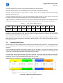
FREQUENCY BAND THEORY ................................................................................................... 33
5.2.1 Frequency Bands and ODU Relationships...................................................................... 34
5.3
OUTDOOR UNIT (ODU) – TECHNICAL DESCRIPTION................................................................. 39
5.3.1 Transmit IF....................................................................................................................... 41
5.3.2 Receive IF........................................................................................................................ 41
5.3.3
RF Up / Down Converter ................................................................................................ 41
5.3.4 RF Diplexer ...................................................................................................................... 41
III
Digital Microwave Radio
8800 series
5.3.5
5.3.6
5.3.7
5.3.8
5.3.9
5.3.10
CHAPTER 6
RF Local Oscillator .......................................................................................................... 41
Cable Multiplexer ............................................................................................................. 42
ODU Controller ................................................................................................................ 42
Power Supply................................................................................................................... 42
Telemetry ......................................................................................................................... 42
IF Cable ....................................................................................................................... 42
SOFTWARE ................................................................................................................ 44
6.1
THE OPERATING SYSTEM........................................................................................................ 44
6.1.1 PSOS ............................................................................................................................... 44
6.1.2 Plug and Play................................................................................................................... 45
6.1.3 Link Supervisory .............................................................................................................. 45
6.2
FEATURES NOT ACCESSIBLE TO THE END USER ....................................................................... 45
6.2.1 Adaptive Receiver Intermediate Frequency. ................................................................... 45
6.2.2 Adaptive Reed-Solomon Forward Error Correction......................................................... 46
6.2.3 The Configurable Parameters.......................................................................................... 47
6.2.4 Initial Power Up................................................................................................................ 47
6.3
LCD DISPLAY ........................................................................................................................ 48
6.3.1 Alarm Messages .............................................................................................................. 48
6.3.2 Self-Test Messages ......................................................................................................... 49
6.3.3 Configuration Messages .................................................................................................. 49
6.3.4 Communication Messages .............................................................................................. 49
6.3.5 Flags ................................................................................................................................ 49
6.3.6 Types of Parameters ....................................................................................................... 49
6.3.7 Types of Values ............................................................................................................... 50
6.3.8 Reset Operations ............................................................................................................. 50
6.4
THE CONTROL PANEL ............................................................................................................. 50
6.4.1 Control Panel Operation .................................................................................................. 51
6.4.2 ATPC, Tx Mute and Switch Over features....................................................................... 52
6.4.3 Tx Mute ............................................................................................................................ 55
6.4.4 Alarm browsing using the touch keys .............................................................................. 55
6.4.5 Changing IDU port capability ........................................................................................... 56
CHAPTER 7
ELEMENT MANAGEMENT ........................................................................................ 57
7.1
MINET OVERVIEW .................................................................................................................. 57
7.1.1 “Left” and “Right” Terminal Convention ........................................................................... 57
7.1.2 MINet Element Manager .................................................................................................. 58
7.1.3 MINet Features ................................................................................................................ 58
7.1.4 MINet Functions............................................................................................................... 58
7.2
APPLICATION CONCEPTS ........................................................................................................ 59
7.2.1 System Security and Password Protection...................................................................... 59
7.2.2 Active Configurations ....................................................................................................... 60
7.2.3 Configuration Files ........................................................................................................... 60
7.2.4 Modifying an Active Configuration ................................................................................... 61
7.2.5 Updating the Active Configuration ................................................................................... 61
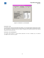
7.2.6 On-screen Save ............................................................................................................... 61
7.2.7 System Messages ........................................................................................................... 61
7.2.8 OFFLINE / ONLINE and NORMAL/CONFIG Modes....................................................... 63
7.3
POLLING ................................................................................................................................ 63
7.4
RESETTING THE LINK AND INDIVIDUAL TERMINALS .................................................................... 64
7.4.1 Reset Link ........................................................................................................................ 64
7.5
BANK SWITCHOVER ................................................................................................................ 64
7.6
SETTING THE FACTORY DEFAULT ............................................................................................ 65
7.7
FUNCTIONS MENU .................................................................................................................. 65
7.8
CONFIGURATION..................................................................................................................... 65
7.8.1 Link Settings .................................................................................................................... 65
7.8.2 Interfaces ......................................................................................................................... 67
7.8.3 Management .................................................................................................................... 70
IV
Digital Microwave Radio
8800 series
7.8.4
7.8.5
7.9.6
7.9.7
7.9.8
7.9.9
7.9.10
Relays .............................................................................................................................. 74
External Inputs ................................................................................................................. 75
Status............................................................................................................................... 76
Performance .................................................................................................................... 77
Alarms Status................................................................................................................... 80
Operations ....................................................................................................................... 81
TFTP Download........................................................................................................... 82
CHAPTER 8
NETWORK MANAGEMENT....................................................................................... 86
8.1
IDU PORTS AND IP ADDRESSES ............................................................................................. 86
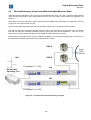
8.1.1 Out Of Band Management............................................................................................... 86
8.1.2 In-band Management....................................................................................................... 88
8.2
USING NMS-IN AND NMS-OUT PORTS .................................................................................. 89
8.2.1 NMS-IN ............................................................................................................................ 89
8.2.2 NMS- OUT ....................................................................................................................... 89
8.3
RIP (ROUTING INTERNET PROTOCOL) ..................................................................................... 89
8.3.1 The Advantages of RIP.................................................................................................... 89
8.3.2 RIP in a cascading configuration ..................................................................................... 89
8.3.3 Using RIP with protected system..................................................................................... 91
8.3.4 Enabling RIP on an Ethernet interface ............................................................................ 92
8.3.5 Configuring 1+1 management system............................................................................. 92
8.4
HP OPENVIEW SUPPORT ....................................................................................................... 93
8.4.1 Introduction to MINet-OV ................................................................................................. 93
8.4.2 MINet-OV Installation....................................................................................................... 93
8.4.3 MINet-OV Features.......................................................................................................... 94
8.4.4 Supported SNMP MIBs........................................................................................................ 95
CHAPTER 9
1+1 PROTECTED CONFIGURATION........................................................................ 96
9.1
1 + 1 COMMON FEATURES...................................................................................................... 96
9.2
HOT STANDBY MODE .............................................................................................................. 97
9.2.1 Configuration - Hot Standby ............................................................................................ 97
9.2.2 Operation - Hot Standby Mode ........................................................................................ 99
9.2.3 Switching Conditions – Hot Standby Mode ..................................................................... 99
9.3
SPACE DIVERSITY MODE ...................................................................................................... 100
9.3.1 Configuration – Space Diversity .................................................................................... 100
9.3.2 Operation – Space Diversity Mode ................................................................................ 100
9.3.3 Switching Conditions – Space Diversity Mode .............................................................. 101
9.4
PROTECTED SYSTEM COMMISSIONING ................................................................................... 102
9.4.1 Protection Mode............................................................................................................. 102
9.5
CONFIGURATION RULES FOR 1 + 1 MODE .............................................................................. 103
9.6
NMS CONFIGURATION FOR 1 + 1 MODE ................................................................................ 103
9.6.1 Hardware Connections .................................................................................................. 103
9.6.2 IDU IP address setting................................................................................................... 104
9.7
MANAGEMENT FOR THE 1 + 1 MODE ...................................................................................... 104
9.7.1 Loading a 1+1 Active Configuration............................................................................... 104
9.7.2 Updating a 1+1 Active Configuration ............................................................................. 105
9.7.3 1+1 Hot Stand-by Switch Over ...................................................................................... 105
9.8
ETHERNET REDUNDANCY VIA THE CODAN 8800 SERIES DIGITAL MICROWAVE RADIO .............. 106
9.7.1 Minimising Spanning Tree settling time......................................................................... 107
CHAPTER 10
FAULT FINDING................................................................................................... 109
10.1
SNMP TRAPS ...................................................................................................................... 109
10.2
EXTERNAL RELAYS ............................................................................................................... 109
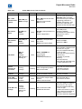
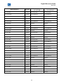
10.3
TROUBLESHOOTING .............................................................................................................. 109
10.4
ISOLATING PROBLEMS ........................................................................................................... 112
10.4.1
Basics ........................................................................................................................ 112
10.5
REPAIRING THE FAULT .......................................................................................................... 112
10.5.1
Make Backups ........................................................................................................... 112
V
Digital Microwave Radio
8800 series
10.5.2
10.5.3
CHAPTER 11
11.1
11.2
11.3
ALARM LIST ........................................................................................................ 114
FATAL ALARMS ..................................................................................................................... 114
USER DEFINED ALARMS........................................................................................................ 118
ADDITIONAL SNMP TRAPS SENT .......................................................................................... 118
CHAPTER 12
12.1
12.2
Safety ........................................................................................................................ 112
Verify the Repair........................................................................................................ 113
FACTORY DEFAULTS......................................................................................... 119
FACTORY DEFAULT SETTING ................................................................................................ 119
FACTORY DEFAULT PARAMETERS .......................................................................................... 119
CHAPTER 13
SPECIFICATIONS ................................................................................................ 122
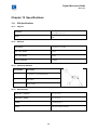
13.1
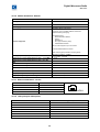
IDU SPECIFICATIONS............................................................................................................ 122
13.1.1
Physical ..................................................................................................................... 122
13.1.2
Electrical .................................................................................................................... 122
13.1.3
Power Port Definition................................................................................................. 122
13.1.4
Environmental............................................................................................................ 122
13.1.5
Platform Architecture ................................................................................................. 123
13.1.6
“N” Type Connector - Frequencies and Levels ......................................................... 123
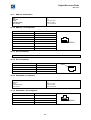
13.1.7
NMS IN - Port Definition ............................................................................................ 123
13.1.8
NMS IN – Pin Configuration ...................................................................................... 123
13.1.9
NMS Out - Port Definition .......................................................................................... 124
13.1.10 NMS Out – Pin Configuration .................................................................................... 124
13.1.11 Eth - Port Definition ................................................................................................... 124
13.1.12 Eth - Port Definition ................................................................................................... 124
13.1.13 Data (RS232) - Port Definition................................................................................... 124
13.1.14 Data (RS232) – Pin Configuration............................................................................. 124
13.1.15 DB25 - Output Relay Specifications .......................................................................... 125
13.1.16 DB25 – Input Specifications ...................................................................................... 125
13.1.17 DB25 – Pin Out.......................................................................................................... 125
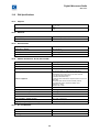
13.2
DIU SPECIFICATIONS............................................................................................................ 126
13.2.1
Physical ..................................................................................................................... 126
13.2.2
Electrical .................................................................................................................... 126
13.2.3
Environmental............................................................................................................ 126
13.24
Platform Architecture - E1, E3, DS1 and DS3........................................................... 126
13.2.5
E1 - Port Definition .................................................................................................... 126
13.2.6
DS1 - Port Definition.................................................................................................. 127
13.2.7
E3/DS3 - Port Definition ............................................................................................ 127
13.2.8
E1/DS1 – RJ45 Pin Out............................................................................................. 127
13.2.9
E1/DS1 – SCSI Pin Out............................................................................................. 127
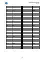
13.2.10 Platform Architecture - Ethernet ................................................................................ 129
13.2.11 Ethernet 10/100 Base-T – Pin out ............................................................................. 129
13.2.12 Latency Delay for PDH systems:............................................................................... 129
13.3
ODU SPECIFICATIONS .......................................................................................................... 130
13.3.1
Physical ..................................................................................................................... 130
13.3.2
Environmental............................................................................................................ 130
13.3.3
“N” Type Connector - Frequencies and Levels ......................................................... 130
13.3.4
Telemetry................................................................................................................... 130
13.4
TRANSMITTERS .................................................................................................................... 132
13.5
RECEIVER ............................................................................................................................ 133
13.5.1
Adjacent Channel Interference.................................................................................. 134
CHAPTER 14
14.1
COMPLIANCE AND STANDARDS ..................................................................... 135
COMPLIANCE ........................................................................................................................ 135
VI
Digital Microwave Radio
8800 series
List of Figures
Figure 1- Typical Codan 8800 series radio link ....................................................................................... 7
Figure 2 - Indoor Unit............................................................................................................................... 8
Figure 3 - IDU Front Panel ...................................................................................................................... 9
Figure 4 - IDU Interface Connections .................................................................................................... 10
Figure 5 - Relay Mapping ...................................................................................................................... 11
Figure 6 - Control Panel ........................................................................................................................ 12
Figure 7 - Front Panel Power and ODU Connections ........................................................................... 14
Figure 8 - Digital Portion Block Diagram. .............................................................................................. 15
Figure 9 - Digital MODEM Block Diagram............................................................................................. 16
Figure 10 - Data Interface Unit 4 E1 BNC + EOW ................................................................................ 19
Figure 11 - Data Interface Unit E3 + 16 E1 ........................................................................................... 19
Figure 12 - Data Interface Unit 16 E1, SCSI ......................................................................................... 20
Figure 13 - Data Interface Unit 16 E1 + E3, SCSI................................................................................. 20
Figure 14 - Data Interface Unit 10/100BaseT + 4E1 ............................................................................. 21
Figure 15 - Data Interface Unit DS3 + 16DS1....................................................................................... 22
Figure 16 - Data Interface Unit 16 DS1, SCSI....................................................................................... 22
Figure 17 - Data Interface Unit 16 DS1 + DS3, SCSI ........................................................................... 23
Figure 18 - Data Interface Unit 10/100BaseT + 4DS1 .......................................................................... 23
Figure 19 - PDH Interface Block Diagram ............................................................................................. 25
Figure 20 - Block Diagram of the Cirrus Logic CS61884-4 8E1/DS1 framer. ....................................... 26
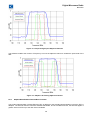
Figure 21 - E1 Pulse Mask .................................................................................................................... 27
Figure 22 - DS1 Pulse Mask.................................................................................................................. 27
Figure 23 - Transformer Coupled Ethernet Interface. ........................................................................... 28
Figure 24 - Ethernet Interface Block Diagram....................................................................................... 28
Figure 25 - Block Diagram of the Link Street 88E6063 7-port Ethernet Switch. ................................... 29
Figure 26 - Ethernet Interface Port Speed Control................................................................................ 30
Figure 27 - Outdoor Unit........................................................................................................................ 31
Figure 28 - Block Diagram of the ODU.................................................................................................. 32
Figure 29 -15 GHz Band ODU Relationships........................................................................................ 33
Figure 30 - 15 GHz ODU Example of Signal Flow ................................................................................ 40
Figure 31 - End-to-End Peer Communications ..................................................................................... 45
Figure 32 - Required Signal plus Adjacent Channel ............................................................................. 46
Figure 33 - Adaptive IF Filtering Adjacent Channel .............................................................................. 46
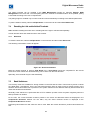
Figure 34 - Main LCD Screen example ................................................................................................. 47
Figure 35 - Receive Signal Level Fluctuations vs. Time ....................................................................... 54
Figure 36 - Link Settings Screen in MINet............................................................................................. 57
Figure 37 - MINet Zoom of LCD showing LED Status .......................................................................... 59
Figure 38 - MINet Initial Authorisations ................................................................................................. 59
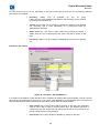
Figure 39 - MINet Load Active Configurations ...................................................................................... 60
VII
Digital Microwave Radio
8800 series
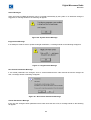
Figure 40 - System Action Message ..................................................................................................... 62
Figure 41 - Illegal Action Message ........................................................................................................ 62
Figure 42 - Non-Critical Parameters Message ...................................................................................... 62
Figure 43 - Critical Parameters Message.............................................................................................. 63
Figure 44 - Reset Confirmation ............................................................................................................. 64
Figure 45 - Interfaces - E1/E3 Tab ........................................................................................................ 67
Figure 46 - Interfaces - Eth 10/100Base-T ............................................................................................ 68
Figure 47 - Interfaces - Services ........................................................................................................... 69
Figure 49 - Management – IP Tab ........................................................................................................ 70
Figure 51 - Management – Peer IP ....................................................................................................... 71
Figure 52 - Management – Routing Table............................................................................................. 72
Figure 53 - Management – Community and Traps Tab ........................................................................ 72
Figure 54 - NMS Management – Change Front Panel Sequence Tab ................................................. 73
Figure 55 - Configuration, Relays - Control Tab.................................................................................... 74
Figure 56 - Configuration, Relays – Mapping Tab ................................................................................ 75
Figure 57 - External Inputs Window ...................................................................................................... 76
Figure 58 - Performance – Link ............................................................................................................. 78
Figure 59 - Performance – Link Thresholds .......................................................................................... 79
Figure 60 - Performance – Eth 10/100 Statistics .................................................................................. 80
Figure 61 - Alarm Status Opening Window – Summary Tab ................................................................ 81
Figure 62 - Loop back test Window....................................................................................................... 82
Figure 63 - TFTP Screen....................................................................................................................... 84
Figure 64 - Out of Band Management via the Eth Port ......................................................................... 87
Figure 65 - In Band Management via 4 x LAN + 4E1/DS1 DIU ............................................................ 88
Figure 66 - Cascaded management using RIP ..................................................................................... 90
Figure 67 - IP Configuration for protected system................................................................................. 91
Figure 68 - MINet – OV Screen ............................................................................................................. 95
Figure 69 - IDU Redundancy................................................................................................................. 96
Figure 70 - SCSI to RJ45 Breakout Panel............................................................................................. 97
Figure 71 - 16E1/E3, 1 + 1 with RJ45 Breakout Panel and Management Redundnacy ....................... 97
Figure 72 - Hot Stand-by configuration. ............................................................................................... 98
Figure 73 - Unequal Redundancy Splitter ............................................................................................. 98
Figure 74 - The RSL Threshold and BER Alarm are configurable items. ............................................. 99
Figure 75 - Space Diversity configuration. .......................................................................................... 100
Figure 76 - The RSL Threshold and BER Alarm are configurable items. ........................................... 102
Figure 77 - Left Hand Terminal IP addressing example...................................................................... 106
Figure 78 - Right Hand Terminal IP addressing example ................................................................... 107
Figure 79 - Ethernet Interfaces Port Configuration ............................................................................. 108
VIII
Digital Microwave Radio
8800 series
List of Tables
Table 3-1
IDU Control Panel Indications.......................................................................................... 13
Table 3-2
Power and ODU Connections.......................................................................................... 14
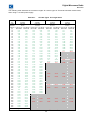
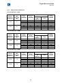
Table 5-1
RSL Volts at BNC connector ........................................................................................... 33
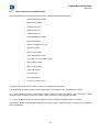
Table 5-2
ITU – 7 GHz – Standard Power ....................................................................................... 35
Table 5-3
ITU – 7 GHz – High Power .............................................................................................. 35
Table 5-4
ITU – 8 GHz – Standard Power ....................................................................................... 36
Table 5-5
ITU – 8 GHz – High Power .............................................................................................. 36
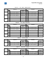
Table 5-6
ITU – 10.5 GHz ................................................................................................................ 36
Table 5-7
ACA, FCC – 10.5 GHz..................................................................................................... 36
Table 5-8
ITU – 13 GHz ................................................................................................................... 37
Table 5-9
ITU, ACA – 15 GHz ......................................................................................................... 37
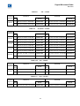
Table 5-10
ITU – 18 GHz ................................................................................................................... 37
Table 5-11
FCC – 18 GHz ................................................................................................................. 37
Table 5-12
ITU – 23 GHz ................................................................................................................... 38
Table 5-13
FCC – 23 GHz ................................................................................................................. 38
Table 5-14
ITU – 26 GHz ................................................................................................................... 38
Table 5-15
ITU – 38 GHz ................................................................................................................... 38
Table 5-16
FCC – 38 GHz ................................................................................................................. 38
Table 5-17
IF Cable Types Vs. Length Chart ................................................................................... 43
Table 6-1
Table of Maximum FEC Performance ............................................................................ 47
Table 6-2
Default Authorisations..................................................................................................... 51
Table 6-3
Table of ATPC definable parameters ............................................................................. 54
Table 6-4
Table of Alarm key functions .......................................................................................... 55
Table 9-1
Protected Terminal Requirements ............................................................................... 103
Table 10-1
Codan 8800 series Fault Conditions ........................................................................... 110
Table 11-1
Fatal Alarms................................................................................................................. 114
Table 11-2
Error Alarms................................................................................................................. 115
Table 11-3
Warning Alarms ........................................................................................................... 116
Table 11-4
User Defined Alarms.................................................................................................... 118
Table 12-1
Data Interface Unit factory default ............................................................................... 120
Table 12-2
Codan 8800 series Terminal Factory Default .............................................................. 120
Table 12-3
Codan 8800 series Software Factory Defaults ............................................................ 121
IX
Digital Microwave Radio
8800 series
Chapter 1
1.1
About this manual
About this issue
This is the first issue of the technical specifications for the Codan 8800 series DMR.
This manual provides a detailed technical description of the Codan 8800 series DMR
components, assemblies software and management topics.
1.2
®
system
Chapter 1
About this manual – explains terms, abbreviations and standards
used in this manual.
Chapter 2
Overview - System building blocks
Chapter 3
System description – Indoor Unit
Chapter 4
System description – Data Interface Units
Chapter 5
System description – Outdoor Units
Chapter 6
Software
Chapter 7
Element Management
Chapter 8
Network Management
Chapter 9
1 + 1 Protected Configuration
Chapter 10
Fault Finding
Chapter 11
Alarm List
Chapter 12
Factory Defaults
Chapter 13
Specifications
Chapter 14
Compliance and Standards
Associated documents
The associated documents are:
Quick Install Guide
Codan 8800 series Reference Manual
MINet Reference Manual
1
Digital Microwave Radio
8800 series
1.3
Standards and icons
The following standards and icons are used in this manual:
This typeface
means
Bold
the name of a button, knob or LED and a segment of text from the display
Bold Times
text that is typed in as a command, or the name of a key on a computer keyboard
Bold times
acceptable command abbreviations
Courier
text that is displayed on a computer screen or in response to a
command
Italic
a cross-reference or text requiring emphasis
This icon
Means
Warning: It is possible that you will seriously damage yourself or the
equipment
Caution: Proceed with caution as your actions may lead to a loss of
data, privacy or signal quality
Note: The text provided next to this icon may be of interest to you
2
Digital Microwave Radio
8800 series
1.4
Definitions
Acronyms and abbreviations
Acronym
Means
AGC
automatic gain control
AIS
alarm indication signal
ANSI
American National Standards Institute
BER
bit error rate
DC
direct current
DIU
data interface unit
DMR
digital microwave radio
DS1
data series 1 (ANSI 1.544 Mbps)
DS3
data series 1 (ANSI 44.736 Mbps)
E1
Electrical data standard 1 (ETSI 2.048 Mbps)
E3
Electrical data standard 3 (ETSI 34.638 Mbps)
EIA
Electronics Industry Alliance
ESR
errored second ratio
ETSI
European Telecommunications Standards Institute
FCC
Federal Communications Commission
GUI
graphical user interface
HPA
high power amplifier
I/O
input/output
IDU
indoor unit
IF
intermediate frequency or inter-facility
ISP
Internet service provider
ITU
International Telecommunications Union
LAN
local area network
LEC
local exchange carrier
LED
light emitting diode
LOS
line-of-sight
3
Digital Microwave Radio
8800 series
Acronym
Means
MIB
management information base
MINet
microwave intelligent network
Mux
multiplexer
N/A
not applicable
NMS
network management system
ODU
outdoor unit
OPA
ODU protected assembly
PCN
personal communications network
PCS
personal communications service
ppm
parts per million
RIP
routing information protocol
RU
rack unit
Rx
receive
SAW
surface acoustic wave
SES
severely errored second
SLIP
serial link Internet protocol
SNMP
simple network management protocol
TCP/IP
transport control protocol/Internet protocol
TFTP
trivial file transfer protocol
TTL
transistor-transistor logic
Tx
transmit
UPS
Un-Interruptable power supply
UTP
unshielded twisted pair
WAN
wide area network
10Base-T
10 Mbps Ethernet via twisted pair
100Base-T
100 Mbps Ethernet via twisted pair
4
Digital Microwave Radio
8800 series
1.5
Units of measurement
Measurement
Unit
Abbreviation
Attenuation
decibel
dB
Current
Ampere
A
Data rate
bits per second
bps
Frequency
Hertz
Hz
Impedance
Ohm
Ω
Length
metre
m
Power
decibels relative to 1 mW
dBm
Power
watt
W
Temperature
degrees Celsius
°C
Voltage
Volts
V
Weight
gram
g
Unit Multipliers
Unit
Name
Multiplier
m
milli
10
d
deci
10
k
kilo
10
M
Mega
10
G
Giga
10
-3
-1
3
6
9
5
Digital Microwave Radio
8800 series
Chapter 2
2.1
Overview
Introduction to the Codan 8800 series series Digital Microwave Radio
The Codan 8800 series is line-of-sight DMR operating in microwave frequency bands between 7 and
38 GHz.
The system supports a wide range of data rates from 3.0 Mbps to 52Mbps.
The modulation format is a form of Continuous Phase Modulation. This modulation provides a high
spectrum efficiency of 1.45 b/Hz and is extremely robust in the presence of interference and multi path
propagation.
The Codan 8800 series provides interfaces to ETSI standard signalling at 2E1 to 16E1 and E3 or
North American digital signalling at 2 DS1 to 16DS1 and DS3. The Codan 8800 series can also
provide a wireless connection for Ethernet 10/100Base-T.
The Codan 8800 series product line serves the following communication markets:
•
Internet Access Systems: Used by Internet Service Providers (Sips).
•
Private Networks: Wireless Bridged LANs.
•
PCS/PCN and Cellular Networks: High-speed links between base stations.
•
Wireless Local Loop Networks: Fixed wireless systems of Local Exchange Carriers
®
The Codan 8800 series terminal/network can be managed by a Windows 98/NT/2000/XP compatible
SNMP network management application called thee Microwave Intelligent Network or MINet.
The Codan 8800 series system has a standard MIB interface that can be managed by HP OpenView
and other similar management platforms.
The Codan 8800 series network management communications are an open system that uses the
TCP/IP protocol to manage all elements of the link
2.2
Basic Structure
The DMR includes two Codan 8800 series terminals. The IDU is installed inside a 19” wiring rackmount, and the ODU and the antenna are mounted outdoors on a tower or rooftop. A single coaxial
cable connects the IDU to the ODU that is directly connected to the antenna.
6
Digital Microwave Radio
8800 series
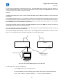
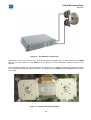
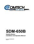
Figure 1- Typical Codan 8800 series radio link
Digital data, service channels, radio overheads and network management information at the local
terminal are fed to the IDU. The IDU converts the digital data to TTL level signals and multiplexes
them with the service channels onto an aggregate data stream.
The IDU digital modem modulates the aggregate signal to create an Intermediate Frequency (IF)
signal. The IF signal is superimposed with DC power and sent to the ODU on a coaxial cable.
The ODU converts the IF signal to a Radio Frequency (RF) signal that is sent to the antenna of the
remote terminal.
At the remote terminal ODU, the received signal is converted back to an IF signal. The IF signal is fed
through the coaxial cable to the IDU, where it is demodulated and de-multiplexed into digital data and
the appropriate service channels.
The link is full duplex (bi-directional), fully symmetrical and transparent to the data stream.
In order to establish a DMR connection, an Codan 8800 series terminal is installed at each site.
These sites designated as the Local site and Remote site as shown in Figure 1, must have a clear line
of sight between each other. The achievable maximum range is determined by the availability
requirements, operating frequency and antenna size.
Each Codan 8800 series terminal is normally mounted to an appropriate microwave parabolic dish
antenna that provides the mounting and alignment devices.
The Link consists of an Indoor Unit (IDU), an Outdoor Unit (ODU) and an antenna as shown in Figure
1. In a typical installation, the IDU is mounted inside a standard 19” rack enclosure and the ODU and
the antenna are mounted on a tower, mast or rooftop.
A single coaxial cable connects the IDU to the ODU; the ODU is mounted directly to the antenna.
Note: The terms ‘Local’ and ‘Remote’ are relative, and depend on the
location from where the system is operated. The ‘Local’ terminal is at
the same location as the operator, The ‘Remote’ terminal becomes
‘Local’ terminal when the operator is at the other site
7
Digital Microwave Radio
8800 series
Chapter 3
3.1
Indoor Units
Indoor Unit Overview
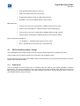
The Indoor Unit (IDU) performs the following functions:
•
Multiplexes and de-multiplexes the customer data channels with the service and supervisory
channels
•
Terminates the coaxial cable from the ODU
•
Provides operator control interface
•
Provides external alarm interface
The indoor unit is housed in a standard 19” rack and is powered by a DC supply voltage of between ± 22 and 60
Volts.
All interfaces are located on the front panel.
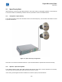
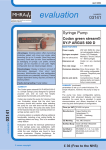
Figure 2 - Indoor Unit
On the front panel, the IDU contains the tributary interfaces, service channels, control panel, DC supply and
network management interfaces. The tributaries and service channels are multiplexed, modulated, converted to
IF, passed along with the DC voltage and telemetry channel on a single cable to the ODU.
A plug-in Digital Interface Unit, located within the IDU, is used to interface various transmission systems with the
IDU. The IDU comprises the modem, tributary multiplexer, power supply and some additional hardware.
The IDU is a software-driven device that operates unattended. The link is configured, operated and monitored
through a user interface. The user can access the system locally through the Control Panel, or from a computer
with MINet installed which may be directly connected to the IDU or remotely through an Ethernet LAN or via a
modem connection.
From the IDU, each segment of the link can be tested, including the tributary, the IDU, the ODU and the
telemetry connection. The remote terminal can also be tested using the local IDU front panel control panel.
Two IDU models are available for international data connections:
The ETSI standard, (European Telecommunications Standards Institute) Codan Part Number 08-06305-001.
The FCC standard, (Federal Communications Commission). Codan Part Number 08-06305-002.
8
Digital Microwave Radio
8800 series
3.2
3.2.1
IDU Physical Description
The IDU Front Panel
Serves as an interconnection panel for interfacing to external equipment by providing access to all the physical
cable connections.
Provides a user interface to the Network Management System through the Control Panel and via a PC
connection with Network Management System software installed
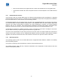
Figure 3 - IDU Front Panel
The IDU contains four functionally distinct areas as follows (from left to right):
{A}
Plug-In Unit that contains Tributary interfaces (E1, E3, DS1, DS3, 10/100Base-T, EOW,
and Redundancy Information)
{B, C, D}
Interface Connections
{B}
Service channels, Data, NMS IN/OUT (asynchronous over TCP/IP),
{C}
Relays and external input connector
{D}
Eth (NMS to LAN) and Test (Factory Use Only)
{E}
Control Panel that contains LCD, keypad, and LED’s
{F}
Power and ODU Connections, DC supply, IDU to ODU connector
Grounding Lug, Reset button and fuse
3.2.2
Digital Interface Unit
The following list details the plug-in DIU models that are currently available.
ETSI
•
4E1, BNC type, 75Ω, plus EOW
•
16E1, RJ45, 120 Ω plus E3, BNC. Used as 2E1 to 16E1, or E3 or E3 + 1E1
•
16E1, SCSI, 75Ω/120 Ω. Used for 2E1 to 16E1 protected configurations
•
16E1, SCSI, 75Ω/120 Ω plus E3, BNC plus EOW. Used for 2E1 to 16E1, or E3 for protected
configurations
•
Four 10/100Base-T plus 4E1
9
Digital Microwave Radio
8800 series
FCC
•
16DS1, RJ45, 100 Ω plus DS3, BNC. Used as 2DS1 to 16DS1, or DS3 or DS3 + 4DS1
•
16DS1, SCSI, 100 Ω. Used for 2DS1 to 16DS1 protected configurations
•
16DS1, SCSI, 100 Ω, plus DS3, BNC plus EOW. Used for 2DS1 to 1DSE1, or DS3 for protected
configurations
•
Four 10/100Base-T plus 4DS1
3.3
IDU Technical Description – Front Panel
3.3.1
Interface Connections
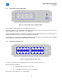
Figure 4 - IDU Interface Connections
The interface connections shown in Figure 4 provide the following:
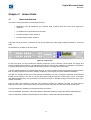
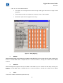
1.
Alarms (DB25 connector - I/O):
Outputs
•
Five user-definable change over relays that can be configured using the MINet software.
•
Any of the equipment alarms can be mapped to any of the relays.
•
Each relay provides normally closed or normally open contacts.
•
A configurable internal audible alarm is also available.
Inputs
•
Four external optically coupled protected inputs at TTL level signals of 2.4 to 9 VDC.
10
Digital Microwave Radio
8800 series
•
With the use of the MINet software:
•
The inputs can be configured to sense low to high level, high to low level or change of state
transitions.
•
The severity level can be configured as a warning, error or fatal condition.
•
All external inputs can be mapped to the relays.
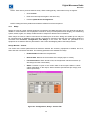
Figure 5 - Relay Mapping
2.
NMS IN:
Network Management System RS232 port cabled to the “NMS Out” port on another IDU for “daisy chaining” the
links or to connect NMS data of multiple IDUs at a common location to manage the network via the SNMP
Protocol.
3.
NMS Out:
Network Management System RS232 port cabled to the “NMS In” port on another IDU for “daisy chaining” the
links or to connect NMS data of multiple IDUs at a common location to manage the network via the SNMP
Protocol.
4.
TEST:
Test port for Codan Limited factory personnel only.
11
Digital Microwave Radio
8800 series
5.
Eth:
Ethernet port for SNMP management via LAN
6.
Data:
RS232 port.
7.
Blank:
Not Used.
3.3.2
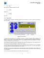
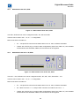
Control Panel
The Control Panel contains the LCD display, keypad and LED indicators. It serves as both the user interface
and Control Panel.
Figure 6 - Control Panel
A stand-alone IDU operating can be configured, monitored, controlled and display system messages and
indications on the Control Panel. An NMS application such as MINet integrated into a Network Management
Station is another means of communicating with the Codan 8800 series terminal and configuring, monitoring,
controlling and displaying system messages.
The Control Panel enables easy system configuration of the local and remote terminals. It also displays the local
and remote terminals status and alarms, statistics and test results.
Current/working parameters and system messages are displayed on the 16 character, two-row, LCD display.
The menu options are grouped and presented on the LCD in a tree structure. The root of each group leads to
the next branch (menu option), descending from top to bottom.
Alarm messages are short messages that are produced by the system and indicate a fault condition. The
messages are displayed in the Control Panel's status information window, and can also be read in the Alarms
Log tab dialog box.
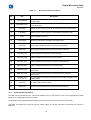
The Control Panel keys and indications are described in the following table.
12
Digital Microwave Radio
8800 series
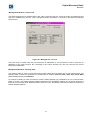
Table 3-1
IDU Control Panel Indications
No
Key
Description
1
Forward Arrow
Scroll forward to choose a command parameter at the same level, or
to edit a digit
2
Backward Arrow
Scroll backward to choose a command parameter at the same level,
or to edit a digit
3
SEL/SAVE
Select or save groups or individual parameters and to enter menus
4
LOC/REM
Select local or remote terminal. LOC/REM LED indicates state
5
ESC
6
LCD Display
7
LOC LED
Green light indicates that the local terminal is selected
8
REM LED
Green light indicates that the remote terminal is selected
9
LOC IDU LED
Yellow indicates malfunction of the local side
10
LOC ODU LED
Yellow indicates malfunction of the local ODU
11
LOC CBL LED
Yellow indicates disconnection or failure of local terminal
12
REM IDU LED
Yellow indicates malfunction of the remote side
13
REM ODU LED
Yellow indicates disconnection or failure of remote terminal
connection
14
REM CBL LED
Yellow indicates disconnection or failure of remote terminal
connection
15
ALARMS LEDs
1, 2, 3, 4, 5
A yellow alarm LED alerts the operator that the Relay mapped to this
LED is active
16
LINK LED
A yellow LED indicates a fault
17
PWR LED
A green LED indicates that the terminal is powered ON
3.3.3
Move upward in the tree
Displays LINK status, messages and parameters
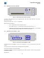
Power and ODU Connections
The IDU can be powered by ±22 - 60 VDC according to the on site services. This can be supplied from either
batteries or a safety approved power supply.
An externally located replaceable fuse protects the power input and is located on the front panel.
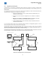
The ODU is powered from the IDU via the coaxial cable. The power and ODU connections are shown in
following:
13
Digital Microwave Radio
8800 series
1
5
2
3
4
Figure 7 - Front Panel Power and ODU Connections
Warning: Always unplug the power cord from the socket before checking the line
fuse to avoid electrical shock.
The IDU power socket has 3 connecting pins. The left connection pin is marked with "V". The centre pin is GND
and marked with an earth symbol, and the right side pin is not used.
When the terminal is rack mounted or two terminals are connected to the same power source, the connection to
the power source must be as following:
The "V" point can be connected to either the positive pole or the negative pole of the power supply.
In the case of two or more IDUs being connected to the same power source, the
polarity of all terminals must be kept the same.
In case of rack mount installation the polarity of the centre or ground point of the
terminal must be the same as the GND point of the power supply.
The following table gives a description of the power and ODU connections.
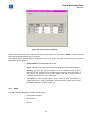
Table 3-2
No
Designation
Power and ODU Connections
Component
Description
1
ODU
Coaxial N-type female connector
2
DC PWR
3-pin receptacle
3
RST
Pushbutton
4
FUSE
FUSE
5
Earth Symbol
Grounding lug
14
Connection to ODU
DC Power IN
(±22 - 60 VDC) -48V typical
Terminal Reset
Amp for –48 VDC
3 Amp for +24 VDC
Ground
Digital Microwave Radio
8800 series
Codan provides a power cable (2 metres long) with colour identifiers. The wire with the RED sleeve should be
connected to the "V" and the plain BLACK wire should be connected to the ground.
As the IDU supports ±22 to 60 VDC, two types of fuses are provided with each IDU to cover the ranges of 22-36
V DC and 36-60 V DC.
When using supply voltage of 22-36 VDC, a 3A fuse should be used. When using supply voltage of 36-60 V DC,
a 1.6A fuse should be used in the IDU.
The Codan 8800 series is shipped with a 1.6 Amp fuse installed, to support 36-60 V DC. An additional fuse, to
support 22-36 V DC, (3 Amp) is also provided.
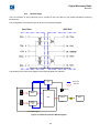
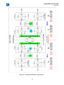
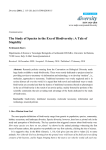
3.4
IDU Technical Description – Architecture
The Codan 8800 series Indoor Unit uses a fully digital architecture, which allows advanced features like digital
bandwidth selection and dynamic Forward Error Correction, and exceptionally low residual BER.
No calibration of any component is required in any stage of the installation and the operation of the radio. The
radio is self-learning based on DSP Processors and programmable logic. In order to maximize performance
Strong FEC is implemented.
The Codan 8800 series is modular, in a way that allow various system configurations, by adding or exchanging
basic blocks.
CLOCK
RAM
Flash
TEMP
CNTRL
DATA
ADDRESS
TEST
D
NMS-IN
D
NMS-OUT
SERIAL
EEPROM
CPU
D
1+1
CONTROL
Reset &
Watchdog
Orderwire
Interf.
LCD
ID
ALARM
RELAYS
KB
Peer
&
NMS
LEDs
Front
Panel
Interf.
Telemetry
Modem
clk
D
RS232
CS
Generator
8530
D
Transparent
Data
A/D
Data
MUX
BERT
MODEM
FEC
ALARM
IN
IB
Interf.
USER TRAFFIC
T1/E1/T3/E3/LAN
Figure 8 - Digital Portion Block Diagram.
15
D/A
ODU
Interf.
Digital Microwave Radio
8800 series
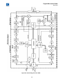
3.4.1
Digital MODEM
The core of the Codan 8800 series is the proprietary Codan ASIC, which is interfaced to the communications
processor.
The result is an advanced digital modem.
A/D
-data
Data
out to
MODEM
BW
Select
AGC
BW
Select
A
RSSI
40.5 MHz
Vref.
180.5 MHz
Serial
D/A
Gain
Control
Limiter
AMP
BPF
Fo=140
Loop Back Circuitry
108MHz
Clock
(3Flb-Ftx)
-45dBm
+5V
Supply
Synth.-RX
13.5 MHz
Sinus
4
13.5 MHz
Ref.
LPF
-30 dBm.
Nom.
140 MHz
LB
Enable
Switch
Tel.-TX Data
Atten.
0dBm
Nom.
400
MHz
4
AM
detector
IDU
MUX
DC
to
ODU
Controller
MPC860
Tel.-TX Data
AM Modulator
Telemetry
TX / RX
Mute
Control
Tel.-RX Data
TX / RX
SW
Synth.-TX
Telemetry Module
A/D
400 MHz
I Data
From
TX
MODEM
Q Data
8
8
D/A
D/A
1 Vptp
I
LPF
LPF
1 Vptp
Q
I &Q
Modulator
P
BPF
A1
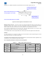
Figure 9 - Digital MODEM Block Diagram.
The digital modem performs the following terminal functions:
Transmit:
o
Scrambles the incoming data from the MUX on the Data Interface Unit
o
Builds the data frame including the addition of FEC
o
Generates the I and Q phases
o
Sets the required transmit bandwidth
o
Generates the Continuous Phase Modulation on the 400 MHz carrier.
o
Sets the required receive bandwidth
o
Demodulates the incoming Continuous Phase Modulated signal.
o
Receives the incoming I and Q phases and converts them to a single serial data stream
Receive:
16
To
ODU
Digital Microwave Radio
8800 series
3.4.2
o
Removes and measures the applied amount of FEC and dismantles the incoming data frame
o
Unscrambles the data and sends composite frames to the de-multiplexer on the Data Interface
Unit.
Communications Processor
The processor used in the Codan 8800 series is a Motorola 32-bit MPC860 series PowerQUICC™ Integrated
Communications Processor which is a versatile one-chip integrated microprocessor and peripheral combination
that excels particularly in communications and networking products.
The MPC860 integrates two processing blocks. One block is the embedded MPC8xx core and the second block
is a Communication Processor Module (CPM) based on the MC68360 CPM. The CPM supports eight serial
channels—four serial communications controllers, two serial management controllers, one serial peripheral
2
interface, and one I C interface. This dual-processor architecture provides lower power consumption than
traditional architectures because the CPM off-loads peripheral tasks from the embedded MPC8xx core.
The MPC860 is supported by 4 MByte of memory, which is configured as two banks of 2 MByte in each bank.
Only one bank of memory is used to support the terminal at any given time.
The Indoor Unit is dispatched from the factory with the most recent version of firmware loaded into each bank of
memory. Each bank of memory can be configured with different versions of firmware, which allows a firmware
upgrade to be carried out whilst the Indoor Unit continues to function with a previous version of firmware.
3.4.3
Operating System
The operating system chosen for the Codan 8800 series of Digital Microwave Radios is PSOS or Proverbially
Secure Operating System.
This system is extremely robust and efficient in network communications devices.
The software supports “Plug and Play” automatic identification and configuration of Data Interface Units and
Outdoor Unit frequency bands.
17
Digital Microwave Radio
8800 series
Chapter 4
4.1
Data Interface Units
Data Interface Unit Overview
The architecture of the Codan 8800 series is designed to make the product very flexible.
The personality of the DMR terminal is determined by choosing one, of several Data Interface Units (DIU).
The Data Interface Units available are:
4.1.1
4.1.2
4.2
ETSI
•
4E1, BNC type, 75Ω, plus EOW for unprotected configurations– Codan part number 08-06306-001
•
16E1, RJ45, 120 Ω plus E3, BNC. Used as 2E1 to 16E1, or E3 or E3 + 1E1 for unprotected
configurations – Codan part number 08-06307-001
•
16E1, SCSI, 75Ω/120 Ω. Used for 2E1 to 16E1 for unprotected or protected configurations – Codan
part number 08-06309-001
•
16E1, SCSI, 75Ω/120 Ω plus E3, BNC plus EOW. Used for 2E1 to 16E1, or E3 for unprotected or
protected configurations – Codan part number 08-06309-003
•
Four 10/100Base-T plus 4E1 – Codan part number 08-06308-001
FCC
•
16DS1, RJ45, 100 Ω plus DS3, BNC. Used as 2DS1 to 16DS1, or DS3 or DS3 + 4DS1 for
unprotected configurations – Codan part number 08-06307-002
•
16DS1, SCSI, 100 Ω. Used for 2DS1 to 16DS1 for unprotected or protected configurations – Codan
part number 08-06309-002
•
16DS1, SCSI, 100 Ω, plus DS3, BNC plus EOW. Used for 2DS1 to 1DSE1, or DS3 for unprotected
or protected configurations – Codan part number 08-06309-004
•
Four 10/100Base-T plus 4DS1 – Codan part number 08-06308-002
DIU Physical Description
Data Interface Units (DIU’s) consist of a small front panel mounted on a circuit board and are described in this
section. The DIU plugs into the recess on the left side front of the Codan 8800 series Indoor Unit.
18
Digital Microwave Radio
8800 series
4.2.1
Data Interface Unit: 4E1, BNC + EOW
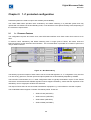
Figure 10 - Data Interface Unit 4 E1 BNC + EOW
The 4 E1 BNC + EOW type DIU can be configured as 2E1 or 4E1.
The inputs support 75 ohm unbalanced. Each channel has a green LED to indicate that the receive path is
active. This DIU can only be used in the 1 + 0 configuration.
This DIU also features an RJ-11 connector for a telephone handset and push button to call the remote side. The
EOW facility enables telephone communications between two terminals.
The handset is a “k” style unit. It incorporates a low-level electric microphone and a dynamic receiver equipped
with a hearing aid coil and a varistor for limiting the receive level.
4.2.2
Data Interface Unit: 16 E1 + E3
Figure 11 - Data Interface Unit E3 + 16 E1
The 16E1 + E3 DIU unit can be configured as 2E1, 4E1, 8E1, 16E1, E3, and E3+1E1.
Data connections are made via
•
E1 – Shielded RJ45 connectors (x 16), 120 Ω
•
E3 – Tx / Rx BNC connectors (x 2), 75 Ω unbalanced
This DIU can only be used in the 1 + 0 configuration.
19
Digital Microwave Radio
8800 series
4.2.3
Data Interface Unit: 16 E1, SCSI
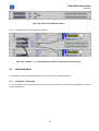
Figure 12 - Data Interface Unit 16 E1, SCSI
The 16E1, SCSI DIU unit can be configured as 2E1, 4E1, 8E1 and 16E1.
This DIU can be used in the 1 + 0, or 1 + 1 configuration.
Data connections are made via:
4.2.4
•
E1 – 100-pin SCSI connector and cable at either 75 Ω or 120 Ω, software selectable.
•
Cables with a SCSI plug to various cable configurations (Open Tail, DB37, etc) are available
and breakout boxes with BNC, DB25, Krone and RJ45 can be supplied.
Data Interface Unit: 16 E1 + E3, SCSI
Figure 13 - Data Interface Unit 16 E1 + E3, SCSI
The 16 E1 + E3, SCSI DIU unit can be configured as 2E1, 4E1, 8E1, 16E1, E3 and E3 + 1E1.
This DIU can be used in the 1 + 0, or 1 + 1 configuration.
Data connections are made via:
•
E1 – 100-pin SCSI connector and cable at either 75 Ω or 120 Ω, software selectable.
•
E3 – BNC at 75 Ω for 1 + 0, 100-pin SCSI connector and cable at 75 Ω for 1 + 1.
•
Cables with a SCSI plug to various cable configurations (Open Tail, DB37, etc) are available
and breakout boxes with BNC, DB25, Krone and RJ45 can be supplied.
20
Digital Microwave Radio
8800 series
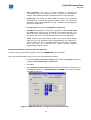
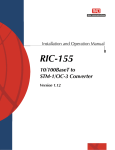
4.2.5
Data Interface Unit: 10/100BaseT + 4 E1
Figure 14 - Data Interface Unit 10/100BaseT + 4E1
The Data Interface Unit 10/100BaseT + 4E1 can be configured as 1, 2, 3 or 4 x LAN plus 0E1, 1E1, 2E1 or 4E1.
The LAN ports can be configured for full or half duplex with auto negotiation.
Each of the 10/100 Base-T ports is fully scalable.
The Ethernet 10/100BaseT connection is equipped with on-line status indications. 2 LED’s on each port perform
the indication as follows:
Left Side LED:
•
HDX Off Half-Duplex while the LED is off
•
FDX G Full-Duplex while the LED is green
•
Collision BG Collisions while the LED is blinking green
•
Disabled Y The Port is disabled while the LED is yellow
Right Side LED:
•
Connect 10 G The port is configured to 10Mbps while the LED is green
•
Activity 10 BG Throughput is 10Mbps while the LED is blinking green
•
Connect 100 Y The port is configured to 100Mbps while the LED is yellow
•
Activity 100 BY Throughput is 100Mbps while the LED is blinking yellow
Data connections are made via:
•
10 / 100Base-T – Shielded RJ45 connectors (x2), 100 Ω
•
E1 – Shielded RJ45 connectors (x4), 120 Ω balanced
21
Digital Microwave Radio
8800 series
4.2.6
Data Interface Unit: 16 DS1
Figure 15 - Data Interface Unit DS3 + 16DS1
The 16DS1 + DS3 DIU unit can be configured to 2DS1, 4DS 1, 8DS 1, 16DS 1, DS3, DS3 +1DS1, DS3
+2DS1and DS3 + 4DS1.
Data connections are made via:
4.2.7
•
DS1 – Shielded RJ45 connectors (x 16), 100 Ω
•
DS3 – Tx / Rx BNC connectors (x 2), 75 Ω unbalanced
Data Interface Unit: 16 DS1, SCSI
Figure 16 - Data Interface Unit 16 DS1, SCSI
The 16DS1, SCSI DIU unit can be configured as 2DS1, 4DS1, 8DS1 and 16DS1.
This DIU can be used in the 1 + 0, or 1 + 1 configuration.
Data connections are made via:
•
E1 – 100-pin SCSI connector and cable at 100 Ω.
•
Cables with a SCSI plug to various cable configurations (Open Tail, DB37, etc) are available
and breakout boxes with DB25, Krone and RJ45 can be supplied.
22
Digital Microwave Radio
8800 series
4.2.8
Data Interface Unit: 16 DS1 + DS3, SCSI
Figure 17 - Data Interface Unit 16 DS1 + DS3, SCSI
The 16DS1 + DS3, SCSI DIU unit can be configured as 2DS1, 4DS1, 8DS1, 16DS1, DS3, DS3 + 1DS1, DS3 +
2DS1 and DS3 + 4DS1.
This DIU can be used in the 1 + 0, or 1 + 1 configuration.
Data connections are made via:
4.2.9
•
DS1 – 100-pin SCSI connector and cable at 100 Ω.
•
DS3 – BNC at 75 Ω for 1 + 0, 100-pin SCSI connector and cable at 75 Ω for 1 + 1.
•
Cables with a SCSI plug to various cable configurations (Open Tail, DB37, etc) are available
and breakout boxes with BNC, DB25, Krone and RJ45 can be supplied.
Data Interface Unit: 10/100Base-T + 4 DS1
Figure 18 - Data Interface Unit 10/100BaseT + 4DS1
The Data Interface Unit 10/100BaseT + 4DS1 can be configured as 1, 2, 3 or 4 x LAN plus 0DS1, 1DS1, 2DS1
or 4DS1.
The LAN ports can be configured for full or half duplex with auto negotiation.
Each of the 10/100 Base-T ports is fully scalable.
The Ethernet 10/100BaseT connection is equipped with on-line status indications. 2 LED’s on each port perform
the indication as follows:
Left Side LED:
23
Digital Microwave Radio
8800 series
•
HDX Off Half-Duplex while the LED is off
•
FDX G Full-Duplex while the LED is green
•
Collision BG Collisions while the LED is blinking green
•
Disabled Y The Port is disabled while the LED is yellow
•
Connect 10 G The port is configured to 10Mbps while the LED is green
•
Activity 10 BG Throughput is 10Mbps while the LED is blinking green
•
Connect 100 Y The port is configured to 100Mbps while the LED is yellow
•
Activity 100 BY Throughput is 100Mbps while the LED is blinking yellow
Right Side LED:
Data connections are made via:
4.3
•
10 / 100Base-T – Shielded RJ45 connectors (x2), 100 Ω
•
DS1 – Shielded RJ45 connectors (x4), 100 Ω balanced
DIU Technical Description – Design
The Codan 8800 series of Data Interface Units are based on advanced E1/DS1 or Ethernet chip sets.
These chipsets are the interface between the user traffic and the digital modem.
Irrespective of the type of model of the Data Interface Unit selected the chip sets used are the same across the
range for the same functionality.
4.3.1
E1/DS1 Design
The Line Interface of every E1/DS1 port is coupled to the user data by high quality impedance matching
transformers. The correct impedance is set in the factory for the Data Interface Units, which use the RJ45 or
BNC connectors, whilst the impedance of the Data Interface Units, which use the SCSI connector, can be set
via the MINet software, by the end user.
24
Digital Microwave Radio
8800 series
CPU
Control Flow
Data Flow
10 Mb port
MUX
PDH E1/DS1
MODEM
Line
Interface
Unit
Terminal 1
MODEM
Terminal 2
PDH Data Interface Unit
Figure 19 - PDH Interface Block Diagram
The PDH ports of the Data Interface Units are based on the Cirrus Logic CS61884-4 8E1/DS1 framer.
This chip set provide a number of advanced features for the PDH interface:
•
Internal AMI, B8ZS, or HDB3 Encoding/Decoding
•
LOS Detection per T1.231, ITU G.775, ETSI 300-233
•
G.772 Non-Intrusive Monitoring
•
G.703 BITS Clock Recovery
•
Crystal-less Jitter Attenuation
•
Serial/Parallel Microprocessor Control Interfaces
•
Transmitter Short Circuit Current Limiter (<50mA)
•
TX Drivers with Fast High-Z and Power Down
•
JTAG Boundary Scan compliant to IEEE 1149.1
25
Digital Microwave Radio
8800 series
Figure 20 - Block Diagram of the Cirrus Logic CS61884-4 8E1/DS1 framer.
The CS61884 is a full-featured Octal E1/T1/J1 short-haul LIU that supports both 1.544 Mbps and 2.048 Mbps
data transmission. Each channel provides crystal-less jitter attenuation that complies with the most stringent
standards.
Each channel provides internal AMI/B8ZS/HDB3 encoding/decoding. To support enhanced system diagnostics.
The chipset can be configured for G.772 non-intrusive monitoring of any of the receive or transmit paths.
The chipset makes use of ultra low power matched impedance transmitters and receivers. By achieving a more
precise line match, this technique also provides superior return loss characteristics.
All transmitters have controls for independent power down and high impedance.
Each receiver provides reliable data recovery with over 12 dB of cable attenuation.
The receiver also incorporates LOS detection compliant to the most recent specifications.
Both the E1 and DS1 interfaces conform to the standard pulse masks.
26
Digital Microwave Radio
8800 series
Figure 21 - E1 Pulse Mask
Figure 22 - DS1 Pulse Mask
27
Digital Microwave Radio
8800 series
4.3.2
Ethernet Design
The Line Interface of every Ethernet port is coupled to the user data by high quality impedance matching
transformers.
The configuration of the Ethernet port is shown in the following diagram:
User Data
8800 DIU
Figure 23 - Transformer Coupled Ethernet Interface.
The following is the basic block diagram of the Ethernet Data Unit Interface:
.
CPU
Control Flow
Data Flow
10 Mb port
SWITCH
10/100 BASE-T
MUX
PDH (4*E1/4*DS1)
MODEM
Line
Interface
Unit
Terminal 1
10/100 ETH Plug-In
Figure 24 - Ethernet Interface Block Diagram.
28
MODEM
Terminal 2
Digital Microwave Radio
8800 series
The Ethernet ports of the Data Interface Units are based on the Marvell Link Street 88E6063 7-port switch.
This 88E6063 device is a 7-port Quality of Service (QoS) switch integrating a high-performance switching fabric
with four priority queues, a high-speed address look-up engine, five 10/100 Ethernet digital PHY ports, two MII
ports, seven independent Media Access Controllers (MACs), Virtual Cable Tester (VCT) technology for
advanced cable diagnostics, 1Mb of memory.
Other advanced features include 802.1p/IPv4/IPv6 traffic classification, 802.1Q VLAN, extensive RMON
counters and special power management techniques for lowest power dissipation.
The 88E6063 switch is optimised for fastest packet routing.
Figure 25 - Block Diagram of the Link Street 88E6063 7-port Ethernet Switch.
The Codan 8800 series Ethernet Data Interface Units support full scalability on each of the Ethernet ports. This
is managed via the MINet software.
29
Digital Microwave Radio
8800 series
Figure 26 - Ethernet Interface Port Speed Control
30
Digital Microwave Radio
8800 series
Chapter 5
5.1
Outdoor Units
Outdoor Unit (ODU) – Overview
The Outdoor Unit (ODU) is a single compact, lightweight unit containing the transmitter, the receiver and the
duplex branching filter.
The housing is common to all frequency bands and is designed to mount directly to antennas up to 1800 mm in
diameter.
The ODU is pressure tested in the factory and then a small plug seals the pressure gland.
The conical profile of the heat sink elements means that high passive cooling efficiency is achieved. An internal
temperature rise of only 8º C with maximum transmit power is noted.
Figure 27 - Outdoor Unit
31
Digital Microwave Radio
8800 series
Figure 28 - Block Diagram of the ODU
32
Digital Microwave Radio
8800 series
The ODU contains the RF section of the link and generates all of the RF signals.
Monitoring and RF status is conveyed between the IDU and ODU via half duplex telemetry.
The ODU can be mounted on a mast, tower or rooftop, and it can be removed from the antenna without
affecting antenna alignment.
The ODU is installed in with the “N” Type connector towards the down position, 45º from vertical. The ODU can
be rotated 90º thus both horizontal polarisation and vertical polarisation are supported.
A BNC connector is provided to monitor the receiver level during antenna alignment. The voltage provided is
linearised such that each 10 dB of receive signal is approximately 600 mV DC. Refer to the following table:
Table 5-1
RSL Volts at BNC connector
RSL
-10
-20
-30
-40
-50
-60
-70
-80
-85
Volts DC
4.9
4.3
3.8
3.2
2.7
2.1
1.6
1.1
0.8
A single low cost coaxial cable is used to communicate between the IDU and the ODU This cable carries the
transmit IF signal from the IDU to the ODU, the receive IF signal back from the ODU to the IDU and the
telemetry signals being passed in both directions.
Power for the ODU is derived from the IDU and is the same supply voltage and polarity as feeds the IDU. A
power supply in the ODU generates the appropriate voltages required. The IF cable also provides DC power to
the ODU from the IDU.
5.2
Frequency Band Theory
Both ETSI and FCC radio standards define Transmit (Tx), and Receive (Rx) frequencies. The spacing between
the Tx and Rx frequencies is fixed, and varies depending on the frequency band in use and the applicable local
standards.
The Codan 8800 series divides most frequency bands into four sub bands, or one ODU per sub band. In some
instances, where the band plan allows a large duplex frequency separation (15 GHz with a 720 MHz split), then
a single pair of Codan 8800 series ODU’s will manage the whole band.
An Codan 8800 series local terminal that transmits on sub-band 1 receives a signal transmitted in sub-band 3
from the remote terminal and vice versa. By the same token, an Codan 8800 series terminal that transmits in
sub-band 4 receives a signal transmitted in sub-band 2 and vice versa.
Shown below is an example of the 15 GHz band with a 420 MHz Duplex Frequency.
Figure 29 -15 GHz Band ODU Relationships
33
Digital Microwave Radio
8800 series
5.2.1
Frequency Bands and ODU Relationships
The Codan 8800 series complies with the following communications/radio standards:
o
CEPT/ERC/REC 12-08E,
o
REC ITU-R F.386-6,
o
ETSI EN 301 Z16
o
REC ITU-R F.747,
o
ETSI EN 301 128
o
CEPT/ERC/REC 12-02E,
o
REC ITU-R F497-5
o
Mexico / ETSI EN 301 128
o
ACA RALI – FX3:
o
REC ITU-R F.636-3,
o
CEPT/ERC/REC/12-07E,
o
FCC Part 101 & Part 15/B & Part 2
o
CEPT/REC/ 12-03E,
o
REC ITU-R F.595-6,
o
ETSI T/R 13-02E,
o
ITU-R F.637-3,
o
ETSI T/R 13-02E,
o T/R 12-01/ITU-R F.749-1,
To achieve full duplex communications, ODU’s are supplied in partner pairs.
The Codan 8800 series will require an ODU partnership of sub bands 1 and 3 or sub bands 2 and 4.
A 1 + 0 link will always have a matched pair of ODU’s, with one of each sub bands 1 and 3 or 2 and 4. These
will always have an odd and even part number. The lowest part number will always be odd.
A 1 + 1 link will always have a two matched pairs of ODU’s, with two sub bands 1 and 3 or 2 and 4.
The following tables show this relationship for the various frequency bands, and the coverage of the respective
ODU combinations.
34
Digital Microwave Radio
8800 series
Terminal “A”
Terminal “B”
Sub-Bands 1 or 2
Sub-Bands 3 or 4
Table 5-2
Frequency
Separation Sub
Band
ITU – 7 GHz – Standard Power
Terminal A
Terminal B
Part No
Sub
Band
Part No
1
ODU, ITU, Tx 7.128 - 7.212 GHz
08-06310-001
3
ODU, ITU, Tx 7.282 - 7.366 GHz
08-06310-002
2
ODU, ITU, Tx 7.212 - 7.268 GHz
08-06310-003
4
ODU, ITU, Tx 7.366 - 7.422 GHz
08-06310-004
1
ODU, ITU, Tx 7.428 - 7.512 GHz
08-06310-009
3
ODU, ITU, Tx 7.582 - 7.666 GHz
08-06310-010
2
ODU, ITU, Tx 7.512 - 7.568 GHz
08-06310-011
4
ODU, ITU, Tx 7.666 - 7.722 GHz
08-06310-012
1
ODU, ITU, Tx 7.1245 - 7.2085 GHz
08-06310-005
3
ODU, ITU, Tx 7.2855 - 7.3695 GHz
08-06310-006
2
ODU, ITU, Tx 7.2085 - 7.265 GHz
08-06310-007
4
ODU, ITU, Tx 7.3695 - 7.4255 GHz
08-06310-008
1
ODU, ITU, Tx 7.253 - 7.358 GHz
08-06310-021
3
ODU, ITU, Tx 7.414 - 7.519 GHz
08-06310-022
2
ODU, ITU, Tx 7.358 - 7.477 GHz
08-06310-023
4
ODU, ITU, Tx 7.519 - 7.631 GHz
08-06310-024
1
ODU, ITU, Tx 7.4245 - 7.4945 GHz
08-06310-013
3
ODU, ITU, Tx 7.5855 - 7.6555 GHz
08-06310-014
2
ODU, ITU, Tx 7.4945 - 7.5645 GHz
08-06310-015
4
ODU, ITU, Tx 7.6555 - 7.7255 GHz
08-06310-016
1
ODU, ITU, Tx 7.428 - 7.540 GHz
08-06310-017
3
ODU, ITU, Tx 7.673 - 7.785 GHz
08-06310-018
2
ODU, ITU, Tx 7.540 - 7.7652 GHz
08-06310-019
4
ODU, ITU, Tx 7.785 - 7.897 GHz
08-06310-020
154 MHz
161 MHz
245 MHz
Table 5-3
Frequency
Separation Sub
Band
ITU – 7 GHz – High Power
Terminal A
Terminal B
Part No
Sub
ODU, ITU, Tx 7.6555 - 7.7255 GHz
Band
Part No
1
ODU, ITU, Tx 7.128 - 7.212 GHz
08-06311-001
3
ODU, ITU, Tx 7.282 - 7.366 GHz
08-06311-002
2
ODU, ITU, Tx 7.212 - 7.268 GHz
08-06311-003
4
ODU, ITU, Tx 7.366 - 7.422 GHz
08-06311-004
1
ODU, ITU, Tx 7.428 - 7.512 GHz
08-06311-009
3
ODU, ITU, Tx 7.582 - 7.666 GHz
08-06311-010
2
ODU, ITU, Tx 7.512 - 7.568 GHz
08-06311-011
4
ODU, ITU, Tx 7.666 - 7.722 GHz
08-06311-012
1
ODU, ITU, Tx 7.1245 - 7.2085 GHz
08-06311-005
3
ODU, ITU, Tx 7.2855 - 7.3695 GHz
08-06311-006
2
ODU, ITU, Tx 7.2085 - 7.265 GHz
08-06311-007
4
ODU, ITU, Tx 7.3695 - 7.4255 GHz
08-06311-008
1
ODU, ITU, Tx 7.253 - 7.358 GHz
08-06311-021
3
ODU, ITU, Tx 7.414 - 7.519 GHz
08-06311-022
2
ODU, ITU, Tx 7.358 - 7.477 GHz
08-06311-023
4
ODU, ITU, Tx 7.519 - 7.631 GHz
08-06311-024
1
ODU, ITU, Tx 7.4245 - 7.4945 GHz
08-06311-013
3
ODU, ITU, Tx 7.5855 - 7.6555 GHz
08-06311-014
2
ODU, ITU, Tx 7.4945 - 7.5645 GHz
08-06311-015
4
ODU, ITU, Tx 7.6555 - 7.7255 GHz
08-06311-016
154 MHz
161 MHz
35
Digital Microwave Radio
8800 series
Table 5-4
Frequency
Separation Sub
Band
ITU – 8 GHz – Standard Power
Terminal A
Terminal B
Part No
Sub
Band
Part No
1
ODU, ITU, Tx 8.279 - 8.335 GHz
08-06312-005
3
ODU, ITU, Tx 8.398 - 8.454 GHz
08-06312-006
2
ODU, ITU, Tx 8.321 - 8.377 GHz
08-06312-007
4
ODU, ITU, Tx 8.440 - 8.496 GHz
08-06312-008
1
ODU, ITU, Tx 8.279 - 8.328 GHz
08-06312-009
3
ODU, ITU, Tx 8.405 - 8.454 GHz
08-06312-010
2
ODU, ITU, Tx 8.321 - 8.370 GHz
08-06312-011
4
ODU, ITU, Tx 8.447 - 8.496 GHz
08-06312-012
1
ODU, ITU, Tx 7.725 - 7.852 GHz
08-06312-001
3
ODU, ITU, Tx 8.036 - 8.164 GHz
08-06312-002
2
ODU, ITU, Tx 7.844 - 7.971 GHz
08-06312-003
4
ODU, ITU, Tx 8.155 - 8.283 GHz
08-06312-004
119 MHz
126 MHz
311.32
MHz
Table 5-5
Frequency
Separation Sub
Band
ITU – 8 GHz – High Power
Terminal A
Terminal B
Part No
Sub
Band
Part No
1
ODU, ITU, Tx 8.279 - 8.335 GHz
08-06313-005
3
ODU, ITU, Tx 8.398 - 8.454 GHz
08-06313-006
2
ODU, ITU, Tx 8.321 - 8.377 GHz
08-06313-007
4
ODU, ITU, Tx 8.440 - 8.496 GHz
08-06313-008
1
ODU, ITU, Tx 8.279 - 8.328 GHz
08-06313-009
3
ODU, ITU, Tx 8.405 - 8.454 GHz
08-06313-010
2
ODU, ITU, Tx 8.321 - 8.370 GHz
08-06313-011
4
ODU, ITU, Tx 8.447 - 8.496 GHz
08-06313-012
1
ODU, ITU, Tx 7.725 - 7.852 GHz
08-06313-001
3
ODU, ITU, Tx 8.036 - 8.164 GHz
08-06313-002
2
ODU, ITU, Tx 7.844 - 7.971 GHz
08-06313-003
4
ODU, ITU, Tx 8.155 - 8.283 GHz
08-06313-004
119 MHz
126 MHz
311.32
MHz
Table 5-6
Frequency
Separation Sub
Band
ITU – 10.5 GHz
Terminal A
Terminal B
Part No
Sub
Band
Part No
1
ODU, ITU, Tx 10.504 – 10.548 GHz
08-06443-001
3
ODU, ITU, Tx 10.592 – 10.636 GHz
08-06443-002
2
ODU, ITU, Tx 10.548 – 10.592 GHz
08-06443-003
4
ODU, ITU, 10.636 –10.680 GHz
08-06443-004
91 MHz
Table 5-7
Frequency
Separation Sub
Band
ACA, FCC – 10.5 GHz
Terminal A
Terminal B
Part No
Sub
Band
Part No
1
ODU, ACA, Tx 10.550 – 10.583 GHz
08-06442-001
3
ODU, ACA, Tx 10.615 – 10.648 GHz
08-06442-002
2
ODU, ACA, Tx 10.582 – 10.615 GHz
08-06442-003
4
ODU, ACA, 10.647 –10.680 GHz
08-06442-004
65 MHz
36
Digital Microwave Radio
8800 series
Table 5-8
Frequency
Separation Sub
Band
ITU – 13 GHz
Terminal A
Terminal B
Part No
Sub
Band
Part No
1
ODU, ITU, Tx 12.751 - 12.863 GHz
08-06433-001
3
ODU, ITU, Tx 13.017 - 13.129 GHz
08-06433-002
2
ODU, ITU, Tx 12.863 - 12.975 GHz
08-06433-003
4
ODU, ITU, Tx 13.129 - 13.241 GHz
08-06433-004
266 MHz
Table 5-9
Frequency
Separation Sub
Band
ITU, ACA – 15 GHz
Terminal A
Terminal B
Part No
Sub
Band
Part No
1
ODU, ITU, Tx 14.628 - 14.767 GHz
08-06315-001
3
ODU, ITU, Tx 14.943 - 15.082 GHz
08-06315-002
2
ODU, ITU, Tx 14.760 - 14.911 GHz
08-06315-003
4
ODU, ITU, Tx 15.075 - 15.226 GHz
08-06315-004
1
ODU, ITU, Tx 14.501 - 14.725 GHz
08-06315-005
3
ODU, ITU, Tx 14.921 - 15.145 GHz
08-06315-006
2
ODU, ITU, Tx 14.718 - 14.928 GHz
08-06315-007
4
ODU, ITU, Tx 15.138 - 15.348 GHz
08-06315-008
1
ODU, ITU, Tx 14.403 - 14.634 GHz
08-06315-013
3
ODU, ITU, Tx 14.893 - 15.124 GHz
08-06315-014
2
ODU, ITU, Tx 14.627 - 14.858 GHz
08-06315-015
4
ODU, ITU, Tx 15.117 - 15.348 GHz
08-06315-016
1
ODU, ACA, Tx 14.500 - 14.7125 GHz
08-06315-009
3
ODU, ACA, Tx 14.925 - 15.1375 GHz
08-06315-010
2
ODU, ACA, Tx 14.7125 - 14.925 GHz
08-06315-011
4
ODU, ACA, Tx 15.1375 - 15.350 GHz
08-06315-012
315 MHz
420 MHz
490 MHz
644 MHz
Table 5-10
Frequency
Separation Sub
Band
ITU – 18 GHz
Terminal A
Terminal B
Part No
Sub
Band
Part No
1
ODU, ITU, Tx 17.714 – 18.190 GHz
08-06316-001
3
ODU, ITU, Tx 18.724 – 19.200 GHz
08-06316-002
2
ODU, ITU, Tx 18.190 – 18.666 GHz
08-06316-003
4
ODU, ITU, Tx 19.200 – 19.626 GHz
08-06316-004
1010 MHz
Table 5-11
Frequency
Separation Sub
Band
1560 MHz
1
FCC – 18 GHz
Terminal A
ODU, FCC, Tx 17.700 – 18.140 GHz
Terminal B
Part No
Sub
Band
08-06316-005
3
37
Part No
ODU, FCC, Tx 19.260 – 19.700 GHz
08-06316-006
Digital Microwave Radio
8800 series
Table 5-12
Frequency
Separation Sub
Band
1008 MHz
ITU – 23 GHz
Terminal A
Terminal B
Part No
Sub
Band
Part No
1
ODU, ITU, Tx 22.000-22.592
08-06317-001
3
ODU, ITU, Tx 23.008-23.600
08-06317-002
1
ODU, ITU, Tx 21.20-21.80
08-06317-003
3
ODU, ITU, Tx 22.40-23.00
08-06317-004
2
ODU, ITU, Tx 21.80-22.40
08-06317-005
4
ODU, ITU, Tx 23.00-23.60
08-06317-006
1
ODU, ITU, Tx 21.224-21.784
08-06317-007
3
ODU, ITU, Tx 22.456-23.016
08-06317-008
2
ODU, ITU, Tx 21.784-22.344
08-06317-009
4
ODU, ITU, Tx 23.016-23.576
08-06317-010
1200 MHz
1232 MHz
Table 5-13
Frequency
Separation Sub
Band
FCC – 23 GHz
Terminal A
Terminal B
Part No
Sub
Band
Part No
1
ODU, FCC, Tx 21.20-21.80
08-06317-011
3
ODU, FCC, Tx 22.40-23.00
08-06317-012
2
ODU, FCC, Tx 21.80-22.40
08-06317-013
4
ODU, FCC, Tx 23.00-23.60
08-06317-014
1200 MHz
Table 5-14
Frequency
Separation Sub
Band
ITU – 26 GHz
Terminal A
Terminal B
Part No
Sub
Band
Part No
1
ODU, ITU, Tx 24.549 - 24.997 GHz
08-06318-001
3
ODU, ITU, Tx 25.557 - 26.005 GHz
08-06318-002
2
ODU, ITU, Tx 24.997 - 25.445 GHz
08-06318-003
4
ODU, ITU, Tx 26.005 - 26.453 GHz
08-06318-004
1008 MHz
Table 5-15
Frequency
Separation Sub
Band
ITU – 38 GHz
Terminal A
Terminal B
Part No
Sub
Band
Part No
1
ODU, ITU, Tx 37.506 - 37.842 GHz
08-06319-001
3
ODU, ITU, Tx 38.766 – 39.102 GHz
08-06319-002
2
ODU, ITU, Tx 37.842 - 38.178 GHz
08-06319-003
4
ODU, ITU, Tx 39.102 – 39.438 GHz
08-06319-004
1260 MHz
Table 5-16
Frequency
Separation Sub
Band
FCC – 38 GHz
Terminal A
Terminal B
Part No
Sub
Band
Part No
1
ODU, FCC, Tx 38.600 - 38.950 GHz
08-06319-005
3
ODU, FCC, Tx 39.300 - 39.650 GHz
08-06319-006
2
ODU, FCC, Tx 38.950 - 39.300 GHz
08-06319-007
4
ODU, FCC, Tx 39.650 - 40.000 GHz
08-06319-008
700 MHz
38
Digital Microwave Radio
8800 series
5.3
Outdoor Unit (ODU) – Technical Description
The ODU consists of the following functions:
•
Transmit IF
•
Receive IF
•
RF Head Up/Down Converter
•
RF Duplexer
•
RF Local Oscillator
•
The Cable Multiplexer
•
ODU Controller
•
Power Supply
•
Telemetry
•
IF Cable
39
Digital Microwave Radio
8800 series
Figure 30 - 15 GHz ODU Example of Signal Flow
40
Digital Microwave Radio
8800 series
5.3.1
Transmit IF
The transmit IF module converts the 400 MHz input signal received from the Indoor Unit (IDU) to a conditioned
IF signal in 1.0 to 3.0 GHz frequency range. This IF signal is then transferred to the RF Head up converter.
The transmit IF consists of an input buffer amplifier, a monolithic limiter, a low pass filter, a 30dB variable
attenuator to control the output power (P/C), an up-converter mixer driven by its transmit IF LO synthesiser and
finally an output stage.
The transmit IF output stage consists of two serial band pass filters and a switched bypass utilised during ODU
Loop-Back.
5.3.2
Receive IF
The receive IF module converts the IF input signal coming from the RF Head to a frequency in the 1.5 to 3.0
GHz range down to a nominal 140 MHz output to be transferred to the IDU.
It consists of an input stage, down-converter including receive IF synthesiser, low pass filter, limiter and buffer
amplifier. The limiter also provides the RSSI information required to display Received Signal Level (RSL) during
service and antenna alignment.
The input stage consists of variable Attenuator, an amplifier and two serial band pass filters for image rejection.
5.3.3
RF Up / Down Converter
This microwave module includes both transmit and receiver sections.
The transmit section consists of an up-converter from S band to the microwave band with an incorporated LO
frequency multiplier, a power amplifier (PA), a power detector with a closed loop level control.
The receiver down converter section consists of a low noise amplifier (LNA) and a down-converter IRM mixer
from the microwave band to S band. The receiver has its own LO frequency multiplier.
5.3.4
RF Diplexer
The diplexer consists of two band pass filters. One band pass filter for the receiver band and the other for the
transmit band.
Both filters have a common port, which is connected to the antenna.
An additional band pass filter covering the same band as the transmitter is incorporated in the same enclosure.
This filter is connected between the mixer output in RF Head up converter, and the PA input to reduce local
oscillator leakage.
5.3.5
RF Local Oscillator
The RF local oscillator includes an S band synthesiser (~2 GHz) followed by an x2, ×3 or x4 frequency multiplier
(depending on the required RF frequency and the choice of IF).
The multiplied output is typically in the range of 7 to 11 GHz.
41
Digital Microwave Radio
8800 series
5.3.6
Cable Multiplexer
The cable multiplexer is a passive device which separates or combines all to signals on the IF cable and
handles the IF to and from the IDU, DC power supply and telemetry signals.
5.3.7
ODU Controller
The ODU Controller includes the digital circuitry and micro controller and performs the task of interfacing to the
IDU commands and controls and monitors the functions of the ODU hardware –(Synthesisers, Attenuators,
Telemetry, Mute … etc.).
5.3.8
Power Supply
The Power supply consists of a DC/DC converter and some additional voltage regulators.
The IDU supply voltage of +/- 22 to +/- 62 Volts to the DC/DC input is converted to the following output voltages:
•
+15 Volts,
•
+8 Volts and
•
+3.3 Volts
Voltage regulators following the DC/ DC converter produce the following additional output voltages:
•
+5 Volts,
•
-5 Volts and
•
+6 Volt
These voltages are used for common digital circuitry and the RF Head up/down converter.
The overall power handling of the power supply is 30Watts.
5.3.9
Telemetry
The ODU communicates with the IDU via a telemetry modem. Control signals are sent up from the IDU and
status reports are sent down from the ODU. The control signals are sent on a 13.5 MHz Amplitude Modulated
carrier, and the status reports are sent on a 10 MHz Amplitude Modulated carrier.
The ODU is an RFI shielded enclosure having one functional “N” type interface connector for the signals
between the IDU and the ODU and one BNC connector that is used during the antenna alignment procedure.
The ODU can be mounted directly to antennas up to 1800 mm in diameter or remotely mounted using a remote
mount kit and flexible waveguide.
5.3.10
IF Cable
The design of the Outdoor Unit allows low cost coaxial cable to be used to interconnect the IDU to the ODU.
Note: Codan recommends the use of low loss, 100% shield
coaxial cable with an Ultra Violet stabilised outer jacket.
42
Digital Microwave Radio
8800 series
The following table indicates the maximum lengths for various types of Times Microwave® coaxial cable,
when using a –48 VDC power supply.
Table 5-17
K1
K2
0.24788
0.00085
IF Cable Types Vs. Length Chart
0.40123
0.00085
0.79426
0.00108
1.17086
0.00154
Cable
LMR-600
LMR-400
LMR-240
LMR-200
Diameter
15 mm
10.3 mm
6.1 mm
4.95 m
Distance Loss @ 140 Loss @ 400 Loss @ 140 Loss @ 400 Loss @ 140 Loss @ 400 Loss @ 140 Loss @ 400
(m)
MHz in dB MHz in dB MHz in dB MHz in dB
MHz in dB
MHz in dB MHz in dB
MHz in dB
10
0.31
0.53
0.49
0.84
0.95
1.63
1.41
2.4
20
0.61
1.06
0.97
1.67
1.91
3.26
2.81
4.81
30
0.92
1.59
1.46
2.51
2.86
4.9
4.22
7.21
40
1.22
2.12
1.95
3.35
3.82
6.53
5.63
9.61
50
1.53
2.65
2.43
4.18
4.77
8.16
7.03
12.02
60
1.83
3.18
2.92
5.02
5.73
9.79
8.44
14.42
70
2.14
3.71
3.41
5.86
6.68
11.42
9.85
16.82
80
2.44
4.24
3.89
6.69
7.64
13.05
11.26
19.23
90
2.75
4.77
4.38
7.53
8.59
14.69
12.66
21.63
100
3.05
5.3
4.87
8.36
9.55
16.32
14.07
24.03
110
3.36
5.83
5.35
9.2
10.5
17.95
15.48
26.44
120
3.66
6.36
5.84
10.04
11.46
19.58
16.88
28.84
130
3.97
6.89
6.33
10.87
12.41
21.21
18.29
31.24
140
4.27
7.42
6.81
11.71
13.37
22.84
19.7
33.65
150
4.58
7.95
7.3
12.55
14.32
24.48
21.1
36.05
160
4.88
8.48
7.79
13.38
15.28
26.11
22.51
38.45
170
5.19
9.01
8.27
14.22
16.23
27.74
23.92
40.86
180
5.49
9.54
8.76
15.06
17.19
29.37
25.32
43.26
190
5.8
10.07
9.25
15.89
18.14
31
26.73
45.66
200
6.1
10.6
9.73
16.73
19.1
32.63
28.14
48.07
210
6.41
11.12
10.22
17.57
20.05
34.27
29.55
50.47
220
6.71
11.65
10.71
18.4
21.01
35.9
30.95
52.87
230
7.02
12.18
11.19
19.24
21.96
37.53
32.36
55.28
240
7.32
12.71
11.68
20.08
22.92
39.16
33.77
57.68
250
7.63
13.24
12.17
20.91
23.87
40.79
35.17
60.08
260
7.94
13.77
12.65
21.75
24.83
42.42
36.58
62.49
270
8.24
14.3
13.14
22.58
25.78
44.06
37.99
64.89
280
8.55
14.83
13.63
23.42
26.74
45.69
39.39
67.29
290
8.85
15.36
14.11
24.26
27.69
47.32
40.8
69.7
300
9.16
15.89
14.6
25.09
28.65
48.95
42.21
72.1
310
9.46
16.42
15.09
25.93
29.6
50.58
43.62
74.5
320
9.77
16.95
15.57
26.77
30.56
52.22
45.02
76.91
330
10.07
17.48
16.06
27.6
31.51
53.85
46.43
79.31
340
10.38
18.01
16.55
28.44
32.47
55.48
47.84
81.71
350
10.68
18.54
17.03
29.28
33.42
57.11
49.24
84.12
360
10.99
19.07
17.52
30.11
34.38
58.74
50.65
86.52
370
11.29
19.6
18.01
30.95
35.33
60.37
52.06
88.92
380
11.6
20.13
18.49
31.79
36.29
62.01
53.46
91.33
390
11.9
20.66
18.98
32.62
37.24
63.64
54.87
93.73
400
12.21
21.19
19.47
33.46
38.2
65.27
56.28
96.13
410
12.51
21.72
19.95
34.29
39.15
66.9
57.68
98.54
420
12.82
22.25
20.44
35.13
40.11
68.53
59.09
100.94
430
13.12
22.78
20.93
35.97
41.06
70.16
60.5
103.34
440
13.43
23.31
21.41
36.8
42.02
71.8
61.91
105.75
450
13.73
23.84
21.9
37.64
42.97
73.43
63.31
108.15
460
14.04
24.37
22.39
38.48
43.93
75.06
64.72
110.55
470
14.34
24.9
22.87
39.31
44.88
76.69
66.13
112.96
480
14.65
25.43
23.36
40.15
45.84
78.32
67.53
115.36
490
14.95
25.96
23.85
40.99
46.79
79.95
68.94
117.76
500
15.26
26.49
24.33
41.82
47.75
81.59
70.35
120.17
Green – Length is acceptable
Red – Length is unacceptable
43
Digital Microwave Radio
8800 series
Chapter 6
Software
The software architecture consists of four elements:
1
The operating system,
2
Features not accessible to the end user
3
The configurable parameters, accessible to the end user,
4
The Control Panel,
6.1
The Operating System
6.1.1
PSOS
The operating system used in the Codan 8800 series is the Proverbially Secure Operating System or PSOS.
The capabilities of PSOS provide a flexible naming and protection mechanism, and are used to implement
arbitrarily complex subsystems efficiently fulfilling the wide variety of requirements of the Codan 8800 series
The properties of PSOS that make this possible are summarised as follows.
1. The capability mechanism is extremely simple, with only two operations involving the creation of
capabilities, and none permitting the alteration of capabilities.
2. The operations on capabilities can be completely controlled at the most primitive conceptual level of the
system design and implemented in hardware, and the protection provided is not by passable.
3. Capabilities and other PSOS facilities encourage strong modularity via the creation of data and
procedure abstractions.
4. No special protection mechanisms are necessary to protect system programs.
5. Mechanisms for initialization, backup and recovery, and auditing for both PSOS and its subsystems
can be constructed without subverting the protection mechanism.
6. The access rights of the given capability limit the operations permitted upon the particular object
designated by a given capability.
7. The proper hardware support for PSOS can be implemented using established techniques. The
formal techniques used to design PSOS make implementation straightforward and make formal
verification of correct operation possible.
All of the advantages summarised here makes PSOS and subsystems implemented on PSOS far more secure
and reliable than contemporary operating systems.
44
Digital Microwave Radio
8800 series
6.1.2
Plug and Play
Only one version of the operating system is released from the factory at any time with the software supporting
the “plug and play” approach, automatically recognising the installed DIU and the band plan of the connected
ODU.
The factory releases updated software revisions when new frequency bands are introduced or now software
features are released. Provided the features of the updated software are supported by the hardware, the
firmware in the terminal can be easily upgraded by a Trivial File Transfer Protocol (TFTP) session.
6.1.3
Link Supervisory
Communication between each end of a link is via an overhead 64 kbps peer-to-peer channel using the TCP/IP
protocol.
Peer - 64 Kbps
Channel Bandwidth - from 3.5 Mbps to 52 Mbps
Data
Peer
LAN 10M
Figure 31 - End-to-End Peer Communications
6.2
Features not Accessible to the End User
6.2.1
Adaptive Receiver Intermediate Frequency.
The Codan 8800 series Digital Microwave Radio ODU may use either a 28 MHz or 44 MHz SAW filter.
To overcome the problems of Adjacent Channel rejection, an algorithm in the software determines which side of
the required channel is the adjacent channel or interference signal.
45
Digital Microwave Radio
8800 series
Figure 32 - Required Signal plus Adjacent Channel
The software modifies the receiver IF frequency to move the adjacent channel to outside the pass band of the
filter.
Figure 33 - Adaptive IF Filtering Adjacent Channel
6.2.2
Adaptive Reed-Solomon Forward Error Correction
The Codan implementation of Reed-Solomon FEC is different to the standard implementation in that the FEC is
adaptive. The terminal sets the maximum available bandwidth, and as conditions worsen, the terminal applies a
greater amount of FEC up to the limit of the bandwidth.
46
Digital Microwave Radio
8800 series
Conversely as conditions improve, the amount of FEC required is reduced. Thus the amount of FEC required is
automatically and dynamically applied. This sustains bandwidth for the user data.
The maximum amount of FEC applied will correct up to 20 errored bytes in a 255-byte frame.
This dynamic FEC is available for the entire range plug in Data Interface Units with the exception of the Ethernet
plug in module.
Table 6-1
Table of Maximum FEC Performance
Capacity
Bandwidth
2E1
3.5 MHz
Maximum Errored Bytes
corrected
20 bytes
4E1
7 MHz
20 bytes
8E1
14 MHz
16 bytes
16E1
28 MHz
12 bytes
Ethernet traffic, by nature is bandwidth variable, so the requirement to sustain bandwidth for the user data is not
necessary. In this case for the 4 x LAN + 4E1/DS1 DIU, the degree of FEC available in the Codan 8800 series
DMR is selectable by the end user. The end user can define a fixed level of FEC of either 10 bytes or 20 bytes.
6.2.3
The Configurable Parameters
The basic configuration is done using the IDU Control Panel. The user is guided through the main system
parameters with the assistance of the Quick Configuration menu.
The configuration involves navigation through the IDU Control Panel menus and setting the various parameters.
6.2.4
Initial Power Up.
Initially configure the Codan 8800 series system using the IDU Control Panel.
•
•
•
•
6.2.5
Configuring Link Capacity
Setting Tx Frequency (Channel #)
Setting Channel Spacing
Setting Tx Power
Power Up
When the IDU is connected to power, the unit performs a self-test.
Initialisation messages appear on the Control Panel LCD.
At the end a of the sequence, a “Self Test Passed Successfully” message will be displayed and then, the
following information will be displayed.
BER
RSL
1.000 E-15
-031 PWR +20
Figure 34 - Main LCD Screen example
47
Digital Microwave Radio
8800 series
The screen described in the above is an example only. The actual values may be different from those displayed
above.
The main menu is a display of information on:
•
Current Bit Error Rate (BER) 1.0 E-15 value means: No errors.
•
Receive Signal Level (RSL) in dBm, and
•
Transmit Power Level (PWR) in dBm. The displayed power level presents
the actual working terminal power level.
An alarm screen, over-riding the main LCD screen, may also appear. Since the terminal is not yet configured,
the performance and alarm messages described above may be ignored.
6.3
LCD Display
The Liquid Crystal Display (LCD) has a sixteen character, two-row display on which all messages appear (one
at a time).
The LCD is used to show the following types of messages:
6.3.1
•
Current Operation
•
Alarm
•
Self-test
•
Configuration
•
Communication
•
Flags
•
Parameters
•
Values
•
Reset
Alarm Messages
Alarm messages take priority over all other LCD screens. If an alarm message has been received, it will
override the main LCD screen and will always relate to the most recent alarm detected.
The Codan 8800 series is capable of accumulating up to the last 15 alarm events.
To view the alarms, the user must enter the alarm log branch:
Pressing on the SEL/SAVE key will start an editing session by entering the menu
tree.
Pressing the ◄ and ► keys will navigate to the alarm log.
Pressing on the ESC key will return to the Main LCD Screen.
48
Digital Microwave Radio
8800 series
6.3.2
Self-Test Messages
After a power-on, hard reset, or self-test activation, the “SELF-TEST” running message will appear on the LCD.
If a specific test has failed, the system will display a “SELF-TEST failed” message and wait for the operator’s
confirmation.
If the “SELF-TEST” passed successfully, an appropriate message will be displayed for a few seconds, and then
the Main LCD Screen will automatically open.
6.3.3
Configuration Messages
Configuration involves parameters that apply to an individual terminal and parameters that pertain to both
terminals (local and remote terminals).
During configuration, if the user has changed a parameter that pertains to both terminals of the link, he is
prompted to apply configuration modifications to the other terminal as well.
6.3.4
Communication Messages
When communication problems occur with the remote link terminal, or with the Outdoor Unit over the coax
cable, remote parameters may be unavailable and a “Communication Timeout” message is displayed.
If the Remote Side becomes unavailable during an editing session, the current session must be terminated and
a new editing session attempted later.
6.3.5
Flags
When using the Control Panel, the user must distinguish between the symbols that are displayed as flags to
indicate various parameter conditions.
*
#
6.3.6
Active Values of parameters – those with which the Terminal is currently working – are
indicated by the asterisk symbol.
Parameters that have been saved but which have not yet been activated as current are
indicated by the hash symbol. These parameters are stored in a temporary memory. The user
will be asked to confirm the activation of these parameters in a later stage of the editing
session.
Types of Parameters
There are several types of parameters: read/write, read only or operation parameters.
The Read/Write parameters type are classified to:
•
Action parameters type
•
Static parameters type
Action Parameters are configurable values that are instantaneously effective on the operating Codan 8800
series terminal and not updated and saved in the system configuration. A typical example for this type of
parameter is the “System Reset” under the sub menu “Configuration - Operation”.
Static Parameters are saved in the temporary IDU memory until the Update Configuration operation occurs,
after which the updated configuration becomes active.
49
Digital Microwave Radio
8800 series
A typical example for this type of parameter is the Tx Power under the sub menu “Configuration – Link”.
Read/write parameters can either be selected from a pre-defined system list or a parameter that can be edited
character-by-character. An example of a list-type of parameter is the “Link Capacity”. An example of a
character-by-character edited parameter is the “IP Address”.
6.3.7
Types of Values
Parameter fields require entering different types of values, depending on the parameter. These values may be
integer or IP-type characters.
Integer Values
Integer values are generally displayed in decimal format (some may be hexadecimal).
Numbers may be positive or negative. The +/- sign can also be modified when necessary (Tx Power in dBm
values). The number of digits displayed is automatically determined to enable setting the parameter to values
within the Min-Max value range defined for that parameter.
For a read/write leaf, the number is modified by successively editing each digit of the number.
(IP Addresses).
When the on-the-fly parameters are modified, the system prompts the user to activate the modification
immediately. IP Addresses are an example of such a parameter. IP addresses and IP Subnet Mask definitions
are always displayed in the following standard format (four bytes in decimal format, separated by a stop):
•
000.000.000.000 and where each byte value is in the range of 0 to 255.
These parameters are edited by successively editing each of the digits. The IP’s can be on-line modified without
any effect on the Link operation.
6.3.8
Reset Operations
The Terminal can be manually reset by either software or hardware. Software reset is performed via the IDU
control panel System Reset (Cold reset), or by pressing the IDU RESET pushbutton (Hardware reset). Some of
the parameters like link capacity will automatically perform a reset after modification.
The Factory Default configuration via the IDU control panel is a fixed manufacturer setting of parameters and
values that can be useful for initial operation of a virgin terminal. This Codan 8800 series option might be useful
in faultfinding or when the Link is down due to the mismatch of the configuration programming.
Generally, a new 8800 system is supplied with its virgin ‘Factory Default’ parameters set.
6.4
The Control Panel
For security, access to the terminal is limited by password. Any attempt to read or change parameters from the
Control Panel will activate a screen requesting the appropriate password. There are three types of access
privileges:
•
User (read only)
•
Administrator (read and write access, but no functions that may
affect traffic over the Link)
•
Supervisor (full read/write privileges).
50
Digital Microwave Radio
8800 series
The following table shows the factory set passwords for accessing the Control Panel:
Table 6-2
Default Authorisations
Authorisation
Level
6.4.1
Touch keys
User
ESC
ESC
ESC
ESC
ESC
Administrator
ESC
ESC
SEL/SAVE
SEL/SAVE
SEL/SAVE
Supervisor
ESC
ESC
►
►
►
•
User level authorisation provides read only access.
•
Administrator level authorisation provides read/wrote access to configuration
options that can not stop the link from operating
•
Supervisor level authorisation provides full read/wrote access to all
configuration options
Control Panel Operation
Configuration Editing Session Overview
After the Codan 8800 series system has been powered ON and completed its initialisation process, the Control
Panel shows the Main Menu Screen.
Before starting an editing session, press the LOC/REM Control Panel key, while the main menu screen is
displayed. This selects the local or remote terminal whose configuration is to be viewed/edited.
Start the editing session by pressing the SEL/SAVE key. The system copies the Active Configuration of the
currently selected terminal to the Image Configuration Area (RAM) of the Front Panel, enabling the user to
browse the Configuration.
Scrolling horizontally through tree branches at the same level is done using the forward and backward arrows.
SEL/SAVE is used to select a branch and or choose a sub-branch from within a branch. Clicking SEL/SAVE on
any sub-branch will open the parameters of that sub-branch.
When a parameter is displayed, clicking SEL/SAVE will activate the “edit” mode for that parameter. ESC is used
to exit the “edit” mode and move up the tree up to the highest level.
To end a Control Panel editing session and return to the main branch of the configuration tree, successively
press the ESC key. If at least one parameter value has been modified, the user is prompted to activate the new
configuration, with the update confirmation message.
If the user selects YES with the arrow keys and confirms with the SEL/SAVE key, then the new configuration
that includes all the modifications that has been saved in temporary image memory of the Front Panel, is
immediately activated.
If the user selects NO then the system allows the user to either continue the editing session or exit. If the user
exits at this point then all previously made changes are erased.
51
Digital Microwave Radio
8800 series
Some parameters apply to both terminals. If the parameter is link specific, the user is prompted to save the
changes to both terminals and the update 2 sides message appears.
•
Some parameter changes may cause system reset when activated.
Modification will cause reset of the tributary lines.
•
The user is prompted to activate on-the-fly parameters immediately upon
exiting the editing parameter screen.
To save the configuration, the user is required to return to the main branch of the Configuration tree by
successively pressing the ESC key.
How to Select Values from a List
Values for some parameters can be selected from a predefined list. The Link Capacity parameter is an example.
From the Configuration branch, press SEL/SAVE and scroll to the LINK sub branch using the forward and
backward arrow keys. Press SEL/SAVE again, and scroll to the Link Capacity parameter. Press SEL/SAVE, the
first digit in the second row will be underlined. Using the forward and backward arrow keys scroll until you arrive
at the desired value.
Press ESC to go up the configuration tree.
How to edit character by character
Some of the parameters can be edited on a character-by-character basis. The Link ID parameter is an example.
To access the Link ID parameter, press SEL/SAVE from the Configuration branch. Press SEL/SAVE again for
the LINK sub-branch.
Press SEL/SAVE, and scroll to the Link ID parameter. Press SEL/SAVE again to enter the editing mode. The
first character in the second row will be underlined. Use the forward and backward arrow keys to scroll from 0 to
9. Press SEL/SAVE, and the underline will move to the second character. Edit this parameter in the same
manner. Continue with the same for all next characters.
When finished, press ESC to go up the Configuration tree.
6.4.2
ATPC, Tx Mute and Switch Over features
ATPC
Each terminal of a link controls the transmit level of the other terminal to ensure the receive signal stays within
its own preset limits.
The purpose of Automatic Transmitter Power Control (ATPC) is to make the transmit power more efficient
relative to specific site conditions. The concept is based on obtaining the measured Tx and the RSL values of
both terminals and calculating the differences between the measured powers of each. The algorithm then
decides whether to increase or decrease the Tx value of the other terminal to comply with the preset RSL value
of the first terminal.
The Control Panel parameters that deal with the ATPC are:
•
ATPC Control
•
RSL Optimal
•
RSL Upper Threshold
52
Digital Microwave Radio
8800 series
•
RSL Lower Threshold
•
ATPC Timer
•
ATPC Alarm
It is recommended to allow at least 5dB difference between the Upper, Optimal and Lower RSL parameters.
Main Benefits/Features
•
Reduced frequency “reuse distance” for digital-to-digital and digital-to-analogue links
based on propagation protection models.
•
Reduced interference between hops, for hops that re-use the same frequencies;
•
Improved compatibility with analogue and digital systems at nodal stations;
•
Reduced interference between neighbouring systems or adjacent channels of the same
system;
•
Reduced up-fading problems;
•
Reduced terminal power consumption;
•
Extended equipment MTBF due to lower thermal dissipation
•
Dynamically increase system gain as a countermeasure against rainfall attenuation.
•
Maximum power disabled after a user definable “time out” timer
•
Definable window between lower and upper thresholds.
RSL Optimal Value - the local receive power level that the remote radio’s internal ATPC system will attempt to
maintain over the link. This value is the calculated receive signal level, based on a nominal Tx power output at
the remote end, path loss, and antenna gains.
The other two settings define the range in which the receive level can vary before the remote radio’s internal
ATPC system attempts to take corrective action to bring the signal back to the calculated receive power level.
RSL Upper Threshold - the highest receive power value before the radio attempts corrective action. The
received level must exceed this value for more than 10 seconds before the ATPC action commences.
RSL Lower Threshold - the lowest receive power value before the radio attempts corrective action. The
received level must be lower than this value for more than 10 seconds before the ATPC action commences.
53
Digital Microwave Radio
8800 series
Example, for a -45 dBm normal RSL, the low RSL limit is set at -50 and the high is set at -40.
The receiver would request ATPC of
the remote transmitter to decrease
the Tx power in order to bring the
receive level back into the specified
range.
Upper Threshold Rx Signal Level -40 dBm
Clear Sky Signal Level -45 dBm
Time
The receiver would request
ATPC of the remote
transmitter to increase the
Tx power in order to bring
the receive level back into
Lower Threshold Rx Signal Level -50 dBm
Figure 35 - Receive Signal Level Fluctuations vs. Time
Maximum Power Time Out – As ATPC is used to give protection against path fading, and path fading is a
propagation property, which changes in both time and geographic location, the Codan 8800 series has the
ability to disable ATPC after maximum power has been applied for a user definable amount of time.
The Tx power will default back to the clear sky level. This gives added protection to the network, when
abnormalities may cause Tx power to go to, and remain at maximum.
A user definable alarm can also be generated when maximum power has been applied for the defined time.
Software
The ATPC parameters are configured in software and can be set either via the front panel keypad or via the
MINet Element Manager or the SNMPc based NMS.
The algorithm used to determine when to apply ATPC is based on a perceived fade condition. High BER is only
considered if it occurs simultaneously with a fade condition.
User configurable parameters are defined in the following table:
Table 6-3
Parameter
Tx Power
ATPC?
RSL Optimal
Value
Table of ATPC definable parameters
Description
Range
Default
Set Tx power to maximum allowable to
meet License conditions.
-10 dBm to maximum up to
35 dB in 1 dB increments.
Maximum
Enable/disable ATPC
Yes/No
RSL value calculated for clear sky
conditions
-15 dBm to –90 dBm in
1 dB increments.
54
No
-45 dBm
Digital Microwave Radio
8800 series
RSL Upper
Threshold
RSL Lower
Threshold
ATPC Time
Out?
Timer
Time out timer
Alarm?
Alarm Level
6.4.3
RSL maximum level. Must be at least 1 dB
above optimum value. This value must be
exceeded for more than 10 seconds to
activate ATPC
RSL minimum level. Must be at least 1 dB
below optimum value. This value must be
exceeded for more than 10 seconds to
activate ATPC
-15 dBm to –90 dBm in
1 dB increments.
-40 dBm
-15 dBm to –90 dBm in
1 dB increments.
-50 dBm
Enable/disable ATPC time out
Yes/No
Set time out timer
1 minute to 60 minutes in
1-minute increments.
Enable/disable ATPC time out timer alarm
Yes/No
Define the level of alarm for NMS
Low, Medium, High
No
5 minutes
No
High
Tx Mute
The purpose of Tx Mute is for Link diagnostics and testing verification. The Control Panel parameters are:
•
Tx Mute
•
Pause Tx control
•
Pause Tx period
The pause Tx mechanism activates the Tx Mute for a predefined time, which is set using the Pause Tx period
parameter (up to 36000 sec with a default time of 60 sec.).
6.4.4
Alarm browsing using the touch keys
In the ALARM LOG menu, the touch keys function somewhat differently than in other Control Panel menus
because of the added capability to erase alarms from the queue. Figure 39 shows a description of touch key
operation in the Alarms Menu.
Table 6-4
Key
►
◄
SEL/SAVE
ESC
Table of Alarm key functions
Function
Browse to next alarm. This key does not erase the alarm from the
ALARM LOG queue
Browse to previous alarm. This key does not erase the alarm from
the ALARM LOG queue
Erases the alarm from the ALARM LOG queue.
The message, “Alarm Log Empty” appears when all of the
alarms have been erased.
Exits alarm browsing
55
Digital Microwave Radio
8800 series
For all alarms, a time stamp (in minutes) is displayed on the second row of the LCD.
Viewing the Alarm log in the remote terminal is not possible since each of the terminals reports the Local and
the Remote end problems, and these can be viewed only from the Local terminal.
Each Alarm massage contains its REM or LOC prefix.
6.4.5
Changing IDU port capability
Note: Only a Supervisor with full read/write privileges is authorised to
modify port capacity.
To update the IDU capabilities, the Supervisor must perform the following sequence of tasks:
1. In the Control Panel, scroll using ◄ or ► until Configuration is displayed.
2. Press SEL/SAVE to select Configuration.
3. Scroll using ◄ or ► until Operations is displayed.
4. Press SEL/SAVE to select Operation.
5. Scroll using ◄ or ► until Link Capacity is displayed.
6. Press SEL/SAVE to select Link Capacity
7. Scroll using ◄ or ► until the required Link Capacity is displayed.
8. Press SEL/SAVE to save the new capacity displayed in the LCD. (If an error
occurred, Invalid Value will appear. Press ESC to continue.).
9. Press ESC until Update Changes are displayed.
10. Press Y (Yes). The display will show Changes Updated OK.
11. Continue to press ESC to exit from menu.
56
Digital Microwave Radio
8800 series
Chapter 7
7.1
Element Management
MINet Overview
MINet is an element manager or network management system (NMS) that monitors the status of elements
within a given network. It adjusts their parameters as necessary to ensure proper communications and displays
network elements and their attributes.
Using MINet, operators can configure an Codan 8800 series system, monitor and analyse events, make
adjustments and report network events based on displayed information.
MINet uses the familiar Microsoft Windows environment and the Simple Network Management Protocol (SNMP)
to communicate and manage links having management platforms based on TCP/IP.
7.1.1
“Left” and “Right” Terminal Convention
A few conventions are used in MINet to describe the terminals of a link. In this manual, reference is often made
to the “left terminal” and “right terminal.” Both terminals of a link are symmetrical.
“Left” is the convention used for the terminal whose parameters are displayed on the left hand panel of the main
window. The “left” terminal will have a pink-coloured title bar and a pink-coloured button on the left side of the
IDU image.
“Right” is the convention used for the terminal whose parameters are displayed on the right hand panel of the
main window The “right” terminal will have a blue coloured title bar and a blue coloured button on the left side of
the IDU image. “Right” is the convention used for the terminal displayed in the right panel, which is coloured
blue and has a blue button.
Another convention is “Peer Terminal”. When working with one terminal, “peer” refers to the other terminal of the
same link. For instance, the user can get IP information of the “peer” terminal, by viewing its parameters in the
Peer IP.
Figure 36 - Link Settings Screen in MINet
57
Digital Microwave Radio
8800 series
7.1.2
MINet Element Manager
The Codan 8800 series is equipped with a network management system (NMS).
The Codan 8800 series NMS contains two components:
•
An SNMP-based management system called MINet that is installed on a PC
•
An SNMP agent that is physically embedded in the IDU.
The element manager and agent communicate with one another using the SNMP protocol over TCP/IP. The
SNMP agent contains a database of standard and private SNMP Management Information databases (MIBs).
To acquire information, the management communicates with the agent’s database. Thus, the management
system generally functions as a master and the agent as a slave.
An exception to this master-slave relationship is the handling of important alarm notifications. These agentinitiated messages or alarms, which are sent to the management system, are called traps.
Note that MINet does not have a capability to receive the traps itself
directly but rather re-directs the traps to specific user-determined trap
recipient IP addresses. HP OpenView and some Windows Operating
Systems, for example, have in-built trap manager capabilities.
7.1.3
MINet Features
MINet, provides the following features:
7.1.4
•
A Graphical User Interface (GUI) based windows environment
•
Ability to configure and set a terminal’s properties
•
Ability to view all data port information
•
Remote access over the Internet
•
Traffic monitoring
•
Alarm, status, security, performance, test and configuration management
•
Ability to up load firmware upgrades to local, remote and network terminals
MINet Functions
This section covers the following topics:
•
Defines basic MINet concepts
•
Describes the menu bar.
•
Describes the tollbar and status bar
•
Presents the zoom function of the IDU image
58
Digital Microwave Radio
8800 series
7.2
Application Concepts
MINet enables interrogation of several links, however, only a single link can be active and polled at a time from
a single PC unless MINet integrated into HP OpenView or similar Network Management package is being used.
The parameters of the two terminals of a link are visually represented on screen by left and right panels. MINet
displays a variety of link parameters for purposes of monitoring, configuration and control.
A visual representation of both IDUs of a link can be displayed to show the status of IDU tributary ports and the
IDU’s Front Panel LEDs.
Figure 37 - MINet Zoom of LCD showing LED Status
The parameter windows as well as the Codan 8800 series IDU image are colour coded to display their status at
a glance: green for OK, yellow for warnings, orange for user control, red for fatal errors.
7.2.1
System Security and Password Protection
MINet provides three levels of system access:
•
User (Factory Default Password User)
•
Administrator (Factory Default Password Admin)
•
Supervisor. (Factory Default Password Super)
Figure 38 - MINet Initial Authorisations
59
Digital Microwave Radio
8800 series
System security is automatically activated when there is any unauthorised attempt to modify system
parameters. An authorised user’s attempt to access a function that is not included in the access level for that
user is considered an unauthorised activity. A further level of protection is SNMP Community, which determines
the user’s read/write or read only authorisation.
7.2.2
Active Configurations
Each terminal contains a factory default setting (that cannot be changed by the user), and the factory default is
stored in memory.
When a new terminal is initially booted, the factory settings are loaded as the Active Configuration.
Figure 39 - MINet Load Active Configurations
When a link is initially accessed the parameters of the factory setting can be modified, and this new
configuration becomes the IDU’s Active Configuration.
Each IDU contains an Active Configuration in dedicated non-volatile memory, and this is the actual
configuration that operates the terminal. It is this configuration that is loaded when the user performs Load
Active Configuration. This Active Configuration is also used by the IDU when it is necessary to re-boot the
terminal.
7.2.3
Configuration Files
MINet can work in three modes:
•
OFFLINE mode.
In off line mode, configuration files or parameters are set and stored in a
PC memory as the default. The basic practical use of off line mode is to
set and save a backup of a configuration for future use
•
ONLINE mode.
On line mode is used when MINet communicates with the terminal for
up-loading files from a PC or downloading the Active Configuration that
is stored in the Codan 8800 series terminal.
60
Digital Microwave Radio
8800 series
•
File Mode.
File Mode is used to save an Active Configuration file from the Codan
8800 series terminal to a PC for backup purposes or to make changes
updating the radio. A configuration file can be transmitted to Codan for
technical support. To save .cfg files to a PC file, select Save As from the
File menu.
7.2.4
Modifying an Active Configuration
User capability to modify link parameters depends on the level of access authorisation. This section assumes
that the user has logged on with supervisor authorisation and can change all system parameters.
In MINet, parameters can be changed by entering values or text in fields or by selection from a pull-down menu,
depending on the parameter type. After a selection is made, the modified field will be coloured blue. The blue
colour signifies that the parameter value in the field has been changed on screen. These changes have not yet
been updated to the Active Configuration.
Most parameters have black writing on a white background, ie. these fields can be modified. Other parameters
are displayed for information purposes only and are greyed out.
Some parameters have pull-down list to open, from which the user can select the appropriate value.
7.2.5
Updating the Active Configuration
This section assumes that the Active Configuration has been modified. To update the active configuration
click on Link Operations, Update Active Configuration on the menu bar.
When the Update Active Configuration screen appears select Update First option for the remote terminal.
This is an important precautionary measure. If the remote terminal has been set to update first and it cannot be
updated for some reason, troubleshooting can be done from the local terminal, which is operating. Click OK.
Note: From a Network Management perspective, the Remote Terminal is
the one furthermost down the network. It is not necessarily a
geographical location.
After the link is updated, navigate to the window where the changes have been made, and verify that the
changes are no longer blue. This means that they have been included in the Active Configuration.
7.2.6
On-screen Save
MINet provides a mechanism to ensure that parameter changes are not inadvertently lost. If the user makes
changes in one window (remember, the changes are coloured blue) and opens another window without
updating the Active Configuration or saving to file, then a confirmation message will appear to prompt the
operator to save the changes that have been made.
Click Yes to save these changes temporarily before updating the Active Configuration or saving to a file. If this
is done, the changes will be saved on-screen and other changes can also be made.
7.2.7
System Messages
MINet has a system of messages that prompts the user if parameter changes need further attention. The user is
prompted to confirm the changes and/or perform the designated activity.
61
Digital Microwave Radio
8800 series
Action Messages
Some incorrectly modified parameters can be corrected automatically by the system. If an automatic change is
suggested, a message similar to the following will appear.
Figure 40 - System Action Message
Illegal Action Message
If an attempt is made to save or update an illegal modification, a message similar to the following will appear:
Figure 41 - Illegal Action Message
Non-Critical Parameters Message
If non-critical parameters are changed, and it is recommended that the other terminal should be changed as
well, a message similar to following will appear.
Figure 42 - Non-Critical Parameters Message
Critical Parameters Message
If the user has changed critical parameters that could cause the link to fail, a message similar to the following
will appear.
62
Digital Microwave Radio
8800 series
Figure 43 - Critical Parameters Message
Changes made to certain parameters on one terminal but not the other can cause the link to fail. It is
recommended that the operator should click on the Yes button.
7.2.8
OFFLINE / ONLINE and NORMAL/CONFIG Modes
MINet enables OFFLINE and ONLINE operations.
After the system is powered on and communication between the PC and the Codan 8800 series terminal has
been established, ONLINE is displayed on the status bar. Active Configuration parameters can be updated,
and status and performance can be polled only in the ONLINE mode.
When a parameter is modified in ONLINE mode, the status bar automatically switches from NORMAL to
CONFIG mode. After updating the Active Configuration, the status bar switches back from CONFIG to
NORMAL mode.
In FILE mode, the user can work only with configuration files (.cfg) that have been previously saved from the
terminal while ONLINE mode was active. If a configuration file is saved when the system is on-line, three files
are created. These are:
*.cfg (Link configuration file)
*LU.cfs (Left Terminal status file)
*RU.cfs (Right Terminal status file)
* = Link Name.
In OFFLINE mode, configurations can only be saved as *.cfg and *LU.cfs and *RU.cfs files.
To update an Active Configuration with a configuration file, the system must be in ONLINE mode.
7.3
Polling
Polling status and configuration are activities that are performed when MINet is running and the system is
online. Three different types of polling can be performed:
•
Status polling – polls asynchronous events such as alarms, counters and
status. When status polling is in process, a message will appear on the lefthand side of the status bar.
•
•
Configuration polling – polls all user-changeable configuration parameters.
Performance polling – polls the results of performance indicators such as
BER RSL, Unavailable Time, etc.
63
Digital Microwave Radio
8800 series
The polling intervals can be modified in the NMS Management window by selecting Options, NMS
Management on the menu bar. The initial polling interval in seconds is the default value. Once updated, polling
is executed according to the user’s requirements.
The polling engine is enabled only in online mode and runs automatically according to the defined parameters.
To poll the status manually, select Link Operations on the menu bar and select Poll Status Now.
7.4
Resetting the Link and Individual Terminals
MINet enables resetting the entire link or resetting either the right or left terminal separately.
A reset will shut down and restart the link or the terminal.
7.4.1
Reset Link
To reset the entire link, select Link Operations on the menu bar and then select Reset Link.
The following confirmation screen will appear.
.
Figure 44 - Reset Confirmation
Mark the remote terminal to perform Cold Reset first. If Cold Reset cannot be completed for the remote
terminal for some reason then troubleshooting can be done from the local terminal.
Optionally, each terminal may be reset individually.
7.5
Bank Switchover
Two memory areas are available for storing firmware in the IDU and the ODU. These memory areas or banks
are called Bank 1 and Bank 2. One is the active bank and the other is used to store a backup version of the
firmware. When bank switchover is performed, the system switches to the alternate stand-by firmware bank and
resets the hardware and software.
Generally, bank switchover is performed after a TFTP software up-load or after a system irregularity when the
backup firmware is needed.
For the IDU, the current firmware revisions present in the active and alternate banks are displayed in the
Components Revisions window. For the ODU, only the active firmware version is displayed in the
Components Revisions window.
Performing bank switchover will cause the link to reset. Mark the remote terminal to perform bank switchover
first.
64
Digital Microwave Radio
8800 series
7.6
Setting the Factory Default
A factory default configuration is stored in the IDU memory and enables returning the Active Configuration to
its factory default configuration.
Setting the link to return to factory default configuration will cause the link to reset and the configured IP
addresses and link parameters will be lost. This activity should be performed only after all precautionary
measures have been taken. It is recommended that all current configurations be saved before implementing the
factory default configuration. This is done to prevent the loss of complex configurations.
To set the link to factory default configuration
•
Select Link Operations,
•
Set Factory Default on the menu bar.
Verify that the REMOTE terminal is selected to be activated first.
7.7
Functions Menu
This menu includes all the fields necessary to perform configuration and evaluate status as well as system
testing and up-loading upgrades of system firmware.
The following topics are covered:
•
Performing configuration of the following: link settings, interfaces, agent
management relays and external inputs
•
Evaluating status – examining component revisions, evaluating performance
parameters and viewing system alarms
•
Performing operations such as system testing, TFTP software up-load and bank
switchover
7.8
Configuration
7.8.1
Link Settings
The Link Settings window is the initial parameters window that opens when MINet is started. It can also be
accessed from Functions, Configuration on the menu bar by choosing Link Settings. The window contains 2
tabs.
•
Link Settings – Main Tab
•
Link Settings – Extended tab
Link Settings – Main Tab.
This window contains the basic link data. Some parameters are derived from the hardware and will be read only
as shown by a grey background. Other parameters, which are more performance-oriented, can be modified
from the windows and have a white background. If crucial parameters such as link capacity or channel number
are modified, it is recommended to set the remote terminal to Update First.
The following parameters appear in this tab:
•
Link Name. Text field for the user to enter relevant information.
65
Digital Microwave Radio
8800 series
•
Link IP. Text field for the user to enter relevant information.
•
Plug-in Part Number. Read only field with information read from the IDU. Can
be changed in offline mode.
•
Plug-in Description. Read only field with information read from the IDU.
•
ODU Part Number. Read only field with information read from the ODU. Can be
changed in offline mode.
•
ODU Description. Read only field with information read from the ODU.
•
Link Capacity. Current link capacity. Clicking on the field opens a pull-down list
from which the user can select the relevant link capacity.
•
Channel Spacing. Enables setting the bandwidth for systems that have an Eth
10/100 plug-in. For PDH, channel spacing is automatically determined by link
capacity and therefore does not display on screen.
•
Channel Number. Clicking on the field opens a pull-down list from which the
user can select the appropriate frequency. These channels are listed by an
internal Codan index number with the frequency for the indexed channel
indicated in parenthesis (MHz).
Both terminals must operate on the same channel. If a channel is being
modified, then it is important to update the remote terminal first. Frequency
synthesiser steps for all Codan 8800 series radios are 0.25 MHz except, when
the T/R spacing is 311.32 MHz, which has a step size of 0.1186 MHz.
•
Tx Power Transmission Power. Enables the user to set the transmit power of
the specific ODU. Clicking on the field opens a pull-down list from which the user
can select the relevant transmission power (dBm).
•
System Up-Time. Time that elapsed since the system was last reset.
Link Settings – Extended Tab.
•
Terminal Name. Text field for the user to enter relevant information.
•
Terminal Location. Text field for the user to enter relevant information.
•
Contact Details. Text field for the user to enter relevant information.
•
Force AIS on all E1s. This parameter enables the transmission of AIS as
follows:
•
-
Never,
-
On BER warning,
-
On BER error,
-
Always
FEC Correctable Bytes. The level of FEC for PDH DIU’s is automatically
calculated. For PDH, this is determined automatically according to link capacity.
For PDH DIU’s, the capacity is known and identical capacities always occupy
66
Digital Microwave Radio
8800 series
the same bandwidth. The rest of the bytes of the link are used to carry the FEC
information.
For a LAN DIU, the capacity is variable. Forward Error Correction Adjustment is
available only with the Ethernet LAN DIU. FEC of 10 or 20 bytes of a 255 bytes
frame can be selected. Therefore, 10 bytes of FEC or 20 bytes of FEC, which
occupy about 3 Mbps and are subtracted from Ethernet throughput, can be used
to improve system gain by approximately 1.6 dB. Modifying this parameter
requires resetting the link.
7.8.2
•
ODU Temperature. A built-in feature read from a sensor physically located on
the ODU.
•
Tx Power Level. Actual transmission level as read from the RF head. The user
can compare actual power level with the configured power to which the ODU
was set in the Main tab.
•
ATPC Control Automatic Transmit Power Control. Enables controlling the
transmit power of the terminal according to the remote terminal RSL. It can be
enabled or disabled by clicking on the field. If ATPC is enabled three parameters
can be set:
-
RSL upper threshold,
-
RSL optimal threshold,
-
RSL lower threshold.
Interfaces
Interfaces are hardware with which the system operates and include the service channels and data tributaries.
The Interfaces window is accessed from Functions, Configuration, and Interface on the menu bar.
Interfaces – E1/E3
Figure 45 - Interfaces - E1/E3 Tab
67
Digital Microwave Radio
8800 series
For each E1/DS1 line (up to 16, depending on the type of IDU plug-in) and one E3, the following tributary
parameters are available:
•
Encoding.
HDB3
only
is
available
for
the
E1
ports.
If DS1 ports are being implemented, B3ZS or AMI encoding can be selected
by clicking on the desired cell.
•
Control. Port Control can be enabled or disabled by clicking on the desired
cell. Generally, this is done individually on a port-by-port basis for
administrative purposes.
•
Status Read only. This field is colour coded and provides port status. If
alarms such as Loss of Signal (LOS) are active, they will be shown in this
field.
•
Inv Alarms. Alarms can be enabled or disabled by clicking on the desired
cell.
Interfaces – Eth 10/100
Figure 46 - Interfaces - Eth 10/100Base-T
If an Ethernet 10/100Base-T Data Interface Unit is installed, an Ethernet tab will be available. This tab controls
Ethernet the port parameters of flow control, port control, auto negotiation, port throughput and force disconnect
and provides Ethernet status information on port status, speed status and duplex status.
•
Flow Control can be set to On or Off by clicking on the field. This parameter
must be set to On in order to prevent frames loss. The external port that is
connected to the Eth 10/100 DIU port should also be set to Flow Control On as
the link cannot transmit a full 100 Mbps.
•
Port Control can be set to Enable or Disable by clicking on the field.
68
Digital Microwave Radio
8800 series
•
Port Status is a read only field. If port control is set to enable, alarm status will
be colour coded to indicate actual status.
•
Auto Negotiation. When auto negotiation is set to Off, the user can manually
configure the Speed Control and Duplex Control fields.
•
Speed Control. When auto negotiation is set to Off, Speed Control can be set
to 10 Mbit/s or 100 Mbit/s.
•
Speed Status displays the actual speed that the port detected.
•
Duplex Control. When auto negotiation is set to Off, Duplex Control can be set
to full duplex or half duplex.
•
Duplex Status displays the actual duplex that the port detected.
•
Force Disconnect can be set to Never or On Link Down by clicking on the
field. This will connect or disconnect the port accordingly.
•
Port Throughput can be set to 128 kbps, 256 kbps, 512 kbps, 1 Mbps, 2
Mbps, 4 Mbps, 8 Mbps or unlimited.
Interfaces - Services
Figure 47 - Interfaces - Services
69
Digital Microwave Radio
8800 series
Configuring Services
The Services tab provides access to service channels. Service channels refer to parameters
governing the NMS, Ethernet and Data (serial) ports of the IDU.
The Services tab contains two panels. The upper panel is always read only and shows the Ethernet port MAC
address for IP address management purposes The Eth 10/100 MAC address appears only when using the 4 x
LAN + 4E1/DS1 Data Interface Unit.
The lower panel contains parameters for RS-232 communication: NMS-In, NMS-Out, Data, and Test. It is here
that the user determines the serial communication parameters and whether these ports are enabled or disabled.
7.8.3
Management
The Management window is accessed from Functions, Configuration, and Management on the menu bar.
From this window the Left and Right Terminal IP addresses are defined as well as the routing table. Other
features in this window are definitions of SNMP Community and Traps, as well as software access to the IDU
Front Panel Password Function.
Management Window - IP
The IP tab contains all the terminal’s IP addresses. This tab lists IP and local Subnet Mask addresses for NMS
In (SLIP), NMS Out (SLIP), Link and ETH connection, NMS In (SLIP) Dest, NMS Out (SLIP) Dest.
Figure 48 - Management – IP Tab
70
Digital Microwave Radio
8800 series
Management Window - Peer IP Tab
This option displays the IP address table of the “other” terminal of the link. These are read-only parameters and
cannot be modified from this tab. “Peer” indicates that this information is received by the internal proprietary
peer protocol.
Figure 49 - Management – Peer IP
The Peer IP tab is useful when the user knows the IP addresses of one terminal but wants to know the IP
addresses of the other terminal. By connecting to the known terminal, the user can discover the remote
terminal’s IP addresses.
Management Window - Routing Table
The Routing Table is used to route data among Codan 8800 series terminals and to the outside world. The
Routing Table contains the parameters of Destination IP address (Dest IP Addr), Next Hop, Route Mask
(Subnet Mask number) and Interface.
An example of adding a route command is to add a default gateway (eg. Destination IP is 0.0.0.0 and Route
Mask is 0.0.0.0). The default gateway address determines the destination address for all frames leaving the
terminals to the outside world. When the Dest IP Addr is 0.0.0.0, the address entered in the Next Hop field is the
Default Gateway address.
71
Digital Microwave Radio
8800 series
Figure 50 - Management – Routing Table
Management Window - Community and Traps
Figure 51 - Management – Community and Traps Tab
72
Digital Microwave Radio
8800 series
•
Trap Recipients. The Trap IP recipient address is important for
accumulating system messages that can be utilised for performance
analysis. All IP addresses listed in the table will receive trap messages.
•
Community. Community is a basic SNMP convention and is generally
implemented in a manner that provides system security. The community
designation can be any alphanumeric string. In addition, the privilege type
can also be determined.
•
Privilege types may be set to Read/Write or Read Only.
•
Heart Beat. Heart Beat is a “keep alive” signal plus an optional RSL, BER
and UAS status report that is generated at predefined intervals. The
status report can be generated at 1,10, 30, 60, or 120 minute intervals.
The data is then sent to the trap IP addresses listed in Trap Recipients.
•
Traps. Traps are sent when specific events occur on the network. SNMP
traps are sent to IP addresses that are designated as trap recipients. A
specific SNMP trap can be enabled/disabled by marking the appropriate
check box from the scroll-down list. MINet currently supports
approximately 50 types of traps.
Management Window - Change Front Panel Sequence
In order to gain access to the Front Panel, a five-key PASSWORD must be pressed.
The Front Panel password sequence can be set through MINet as follows.
•
From the Change Front Panel Sequence tab, select the Security Level to be
modified, User, Administrator or Supervisor.
•
Click New
•
In the Change Front Panel Sequence tab, click in a sequence of exactly five of
the following buttons: <, >, SEL/SAVE, ESC, LOC/REM. If you make a mistake,
use Clear to start over.
Figure 52 - NMS Management – Change Front Panel Sequence Tab
73
Digital Microwave Radio
8800 series
NOTE: Take care to press the buttons slowly. When clicking quickly, some buttons may not register.
•
Click Confirm
•
Enter the exact sequence again in the same way.
•
Perform Update Active Configuration.
NOTE: Setting the factory default will reload the default Front Panel sequence.
7.8.4
Relays
Relays are used to control external equipment connected to the 8800 terminals, which are generally not directly
related to communications. Such equipment could be a UPS (Un-Interruptable Power Supply), air conditioning
system, buzzer, lights, etc. Relays enable the IDU to respond to defined sets of conditions.
When relays are used, a cable is connected to the Alarms port on the IDU. Wiring can enable up to 5 relays to
be connected plus an additional relay internally connected to a buzzer inside the IDU. The Relays window is
accessed from Functions, Configuration, and Relays on the menu bar. Alarms are generated for the
equipment in accordance with the parameters in the Control and Mapping tabs of the Relays window.
Relays Window - Control
The Control tab contains parameters that determine whether the accessory equipment is enabled, and if so,
when and how it should be activated. The following parameters are available for relays:
•
Enable/Disable: Enables the relays/buzzer.
•
Normal State: Defines the normal state of the output (open or closed).
•
Forced Activation: When turned to ON, the relay/buzzer will become active (ie.
will change from the normal state).
•
Status: Provides a report of the current state of each output. Status is colourcoded. Depending on the output, status could be Open/Closed (for relays), and
Off/On (for buzzer).
Figure 53 - Configuration, Relays - Control Tab
74
Digital Microwave Radio
8800 series
Relays Window - Mapping
The Mapping tab enables setting the mapping of alarms that will apply to a maximum of five relays and one
buzzer. The actual number of events depends on the IDU configuration and the number of supported tributary
lines.
If check boxes are marked, they define the events or alarms for which the relay and buzzer outputs will be
activated. For any output, mark the check box for the appropriate event. After marking the desired check boxes,
perform Update Active Configuration.
For example, after the RSL Low alarm is marked for relay #1, this relay can be configured and connected to an
external bell. In addition, Alarm LED #1 on the IDU Front Panel will light when activated.
Figure 54 - Configuration, Relays – Mapping Tab
7.8.5
External Inputs
This section describes configuring external sensors. External inputs in an analogue signal range of 2.5V to 9V
are used to alert the Codan 8800 series terminal of events occurring outside the terminal. MINet enables
activating external inputs and viewing their status in the External Inputs window.
For example, a door can be connected to an external input so that when it is opened, an alarm is generated and
appears on screen with a user-defined severity indication.
The External Inputs window is accessed from Functions, Configuration, and External Inputs on the menu
bar.
75
Digital Microwave Radio
8800 series
Figure 55 - External Inputs Window
When external inputs are used, a cable is connected to the Alarms port on the IDU. A DB-25 connector includes
both relays and external input DIU connections.
The External Inputs window displays parameters for up to 4 inputs. For each external input, the following
parameters can be defined:
7.9.6
•
Enable/Disable: Enables/disables the input.
•
Sense: The input can sense Low, High or Any Change to user-defined settings.
•
Severity: The user can set the severity level of the activated input to either
Warning or Fatal. Active inputs can be filtered and sorted by levels of severity. In
this manner, for example, inputs whose voltage level has a severity level of
“Warning” can be ignored, even when active.
•
The status of each external input is colour coded for user convenience as
follows: green (OK – input not activated), yellow (warning), orange (user control),
red (fatal). Otherwise, it will be greyed out.
Status
This menu includes the following system status options:
•
Components revisions
•
Performance
•
Alarms
76
Digital Microwave Radio
8800 series
Components Revisions Status
This option displays information about the hardware and software of system components. For each main system
component (IDU, ODU, DIU), the following information is displayed:
•
Part number
•
Serial number
•
Hardware revision
•
Software revision
•
Alternate software revision, and
•
Boot revision.
The information is especially important for maintenance purposes. The Components Revisions window is
accessed from Functions, Status, and Components Revisions on the menu bar.
7.9.7
Performance
The Performance window contains a large number of performance parameters in three tabbed windows: Link,
Link Thresholds and RSL (Receive Signal Level). If an Ethernet Data Interface Unit is being used, then two
additional tabs are displayed: Eth10/100 Statistics and Eth100 Utilisation.
The user sets some parameters, others are calculated by the system on the basis of user settings, and still
others are calculated by the system independent of user settings.
The Performance window is accessed from Functions, Status, and Performance on the menu bar.
Performance – Link
The Link Tab displays major link statistics for performance indicators and is a performance results window. A
performance value is displayed for each parameter, as well as its percentage relative to the elapsed time. By
using the Period Mode field, the user can choose to sample data in a 24-hour period, since the last reset or for
the current 15-minute period.
By default, MINet colour codes major parameters.
77
Digital Microwave Radio
8800 series
Figure 56 - Performance – Link
Performance - Link Thresholds
This window enables setting the thresholds for link performance parameters. The operator is able to define the
performance parameter when the link switches bot into and out of alarm for4 the following parameters:
•
Unavailable time
•
Errored seconds
•
Severely errored seconds
•
Corrected block rate
•
Background block errors
•
BER warning
•
BER fatal, and
•
Current RSL
78
Digital Microwave Radio
8800 series
Figure 57 - Performance – Link Thresholds
Performance – RSL
This window shows read only RSL performance statistics. The Current dBm Receive Signal Level is colour
coded according to the defined Current RSL threshold setting. The Average, Maximum and Minimum RSL are
also calculated by the system and cannot be changed. The Elapsed Time shows the amount of time that has
elapsed since the last radio restart.
Performance – Eth 10/100 Statistics
This window shows statistics for various Ethernet parameters. This tab is available only if an Ethernet
10/100Base-T DIU is used in the system.
79
Digital Microwave Radio
8800 series
Figure 58 - Performance – Eth 10/100 Statistics
Performance – Eth 10/100 Utilisation
This window shows figures for Ethernet port usage. It will be available only if a 4 x LAN + 4E1/DS1 Data
Interface Unit is used in the system. The displayed parameters comply with the Ethernet MIB standard.
Utilisation is based on the current link throughput available as 100%. For example, if link capacity is Ethernet
only and channel spacing is 28 MHz, then 100% represents 36 Mbps, which is the maximum available
throughput for this configuration.
7.9.8
Alarms Status
MINet enables monitoring the alarm status for all the major components of the Codan 8800 series system being,
Link, ODU, IDU, E1/DS1 (tributaries), (and Eth 10/100). The Alarm Log tab provides a full list of accumulated
alarm messages.
The alarm status of each parameter in each tab is colour coded for user convenience as follows:
•
Green (OK),
•
Yellow (warning),
•
Orange (user control),
•
Red (fatal).
The Alarm Status tabs are accessible from Functions, Status, and Alarms on the menu bar.
80
Digital Microwave Radio
8800 series
Figure 59 - Alarm Status Opening Window – Summary Tab
Clicking on the Save File icon can save the log file. The Save As window will appear and normal windows
conventions apply to save the file to the PC. This function saves the log file as a text file.
7.9.9
Operations
Tests
For link maintenance, several tests have been provided.
To access MINet link tests, select Functions, Tests on the menu bar. The parameters of each test appear in
the test’s tabbed window.
Loopback
Loop back tests can be performed for the local IDU port and the remote IDU port. Although the individual
tributaries of the local IDU port may be looped back, the loop back function does not affect traffic on other ports.
This feature is used to verify whether the designated port is operating correctly.
In this window, the user designates the location of the loop back and the desired tributary or tributaries.
Attaching standard test equipment to one of the IDUs performs the testing. Test results are received at the test
equipment.
81
Digital Microwave Radio
8800 series
Figure 60 - Loop back test Window
Operations
Operations tests enable turning Tx Mute on/off, with or without a timeout period. This feature is used to block
transmission during installation or when interference is being checked on site.
In normal Tx Mute, the user initiates on/off by changing the Value field. Pause Tx functions like normal Tx Mute
except that a timeout period (Pause Tx Period) is set by the user. Pause Tx is typically intended for use with a
remote terminal that is being set to mute, so that a remote terminal will automatically become active again after
the designated time period has elapsed.
7.9.10
TFTP Download
Introduction
The IDU as well as the ODU includes two memory banks to hold the Codan 8800 series firmware. Each bank
can hold identical or different versions of firmware. Typically these versions are the latest up-loaded revision
and the previously up-loaded revision
Either memory bank can be switched to be the active, running a version of firmware.
TFTP (Trivial File Transfer Protocol) is used to upgrade the Codan 8800 series firmware revision. Any TFTP
server can be used for this purpose. The TFTP client/server Codan suggests a freeware program called
Pumpkin from Klever Group, Inc., which can be downloaded from the Internet at the following URL:
http://www.klever.net/kin/index.html
82
Digital Microwave Radio
8800 series
Main Procedural Steps
1.
Establishing an Ethernet connection.
2.
Performing the TFTP process.
Step 1: Establishing an Ethernet Connection
•
Ensure that the terminal is powered-up and working properly.
•
Configure ETH IP on the IDU to be on the same Subnet as the PC.
Example:
PC ETH Mask IP:
255.255.255.000
PC ETH IP:
192.168.1.10
Terminal ETH Mask IP:
255.255.255.000
Terminal ETH IP:
192.168.1.1
•
Connect a crossover cable from the PC ETH port to the IDU ETH port.
•
Ping the IDU from the PC in order to verify communication.
Step 2. TFTP Procedure
•
Start MINet with Supervisor access authorisation
•
It is possible to perform TFTP for one terminal only. When downloading
only to the local terminal clicking the Display button can hide the remote
terminal. This is also true when performing a TFTP download for only the
remote terminal. When a terminal is hidden, polling is turned off for that
terminal, thus the procedure is performed faster
•
Click the Display button to turn off the terminal
•
Click the Load Active Configuration button from the toolbar
•
Enter the IDU IP address, and load the configuration
•
Click OK, and wait until it has loaded
•
Select the TFTP (S/W Download) from the toolbar or from the menu bar
•
Enter the Server IP Address by typing the Server IP Address in the field
provided. The entered IP address is the same PC ETH IP address that was
previously set in step 1.
•
Type the File Name in the appropriate field. (Record either the ODU*.bin
file name or the IDU*.bin file name. Only one is downloaded at a time.)
•
Click Apply Now.
83
Digital Microwave Radio
8800 series
Figure 61 - TFTP Screen
While the TFTP client/server data transfer is in progress, observe that the firmware
file is being transferred to the Codan 8800 series terminal. The PC screen will display
Last Operation: In Process
The In Process message is displayed as for long as the procedure takes to
complete. An up-load to the IDU usually takes only a few seconds. . An up-load to the
ODU can last about 5 minutes.
On completion of the data transfer The TFTP window message shows Last
Operation: Success.
The time to wait for the appearance of the Success message depends on the current
polling interval. If the polling interval had been set to a relatively long time, polling can
be immediately activated by pressing Poll Status Now from the toolbar or from Link
Operations on the menu bar.
Step 3:
Complete the TFTP process as follows.
•
Wait until the Last Operation message shows: Success
•
Proceed with up-loading the IDU*.bin or ODU*.bin file depending on which was
already up-loaded.
After up-loading both the IDU*.bin or ODU*.bin files, a bank switchover may be performed.
Bank Switchover
To perform bank switchover, carry out the following procedure:
•
•
From Link Operations on the menu bar, select Bank Switchover.
Mark the IDU and/or the ODU check boxes, and indicate which terminal, left or
right to switch first.
84
Digital Microwave Radio
8800 series
•
Click OK to finish.
Performing bank switchover will cause the link to reset.
Mark the remote terminal to perform Bank Switchover first. If Bank
Switchover cannot be performed for the remote terminal for some
reason, troubleshooting can be done from the local terminal, which is
still operating.
Do not power down the IDU or the ODU during a firmware up-grade.
85
Digital Microwave Radio
8800 series
Chapter 8
Network Management
This section is intended to convey the basic principles involved in implementing link management using the
different options available for all Codan 8800 series configurations.
Dependant upon which Data Interface Unit is used, link management is performed by assigning IP addresses to
the IDU plug-in ports or by using built-in ports on the standard IDU itself. Typically, a PC with MINet is
connected to one of the terminals. MINet is capable of managing both terminals even if one or both terminals
are remotely installed.
Actual networks may be quite complex. A LAN or the Internet may separate the management PC on which
MINet is installed from the local IDU.
Configurations that have either E1 or DS1 type Data Interface Units use out of band management only. 4 x LAN
+ 4E1/DS1 Data Interface Units have the option to use either in band or out of band management.
8.1
IDU Ports and IP Addresses
The Codan 8800 series architecture provides for the two basic types of management implementations of In
Band and Out Of Band.
An Out Of Band network refers to a link management system in which a dedicated network for link
management purposes connects the terminals.
An In Band network refers to a link management system in which some of the link’s bandwidth used for
customer traffic is allocated for management purposes.
The Codan 8800 series reserves a 64K bandwidth slice for management and other proprietary purposes.
The user can implement In Band or Out Of Band management depending on the link hardware that is used.
The ports of a link are assigned IP addresses, which enable them to find and communicate with one another.
The following ports are available for assigning IP addresses for management purposes.
ETH port.
Out Of Band. This Ethernet 10 Mbit port is the IDU’s main
management port. If the ETH port is implemented as the management
port, it has to be configured for every managed terminal. Each IP
address will have a different Subnet for each terminal.
Ethernet 10/100.
In Band. Available only on terminals where a 4 x LAN + 4E1/DS1 DIU
is installed. Implemented with different IP addresses on the same
Subnet.
NMS-IN (Out Of Band)
Used to manage remote links via modem and telephone or to cascade
terminals at a site.
NMS-OUT (Out Of Band)
Used to cascade terminals at a site.
8.1.1
Out Of Band Management
The ETH port is a 10 Mbit Ethernet port intended for management purposes. It is located on front panel of the
IDU. In some cases, the ETH port would be the only one available for management purposes. The only
constraint is that the input to the ETH port is via an Ethernet protocol and that the ETH port has a designated IP
address.
86
Digital Microwave Radio
8800 series
In cases where management is performed via the link, a 64K bandwidth segment known as a peer channel, is
used for management purposes. The information that enters the local terminal at the IDU ETH port is also used
to manage the remote terminal via the peer channel.
Example
The ETH port behaves like a router in that it enables terminals with two different subnets to communicate with
one another.
The example assumes that a PC is connected to an IDU at one terminal and the PC and the local IDU are on
the same Subnet with different IP addresses. Since the IDU is connected to a remote IDU with another Subnet,
the local ETH port must be informed of the destination to which it should direct remote traffic. Use of a routing
table embedded in the smart IDU ETH port achieves this.
The routing information, which is input from the MINet workstation into the local ETH port, instructs it to direct all
remote traffic that it receives to the remote terminal.
In live implementations, access to the ETH port may be through a LAN, and the addressing scheme is likely to
be more complicated than that presented here.
To be able to manage both terminals, a static route on the management PC must be added. A static route is a
path in a PC’s routing table that is manually configured by a network administrator.
IDU No.1
IDU No.2
Eth Port
Eth Port
IP address
192.168.1.1
Same subnet
IP address
192.168.3.1
Different subnet on
each terminal
IP address
192.168.1.100
Figure 62 - Out of Band Management via the Eth Port
To add a static route, perform the following:
•
Open a DOS session on the management PC.
•
At the command line, use the following syntax to add a static route for the remote terminal.
route add <remote network address>
87
<local network address>
Digital Microwave Radio
8800 series
For example, to add a route for the remote terminal with the address of 192.168.3.1 through local Ethernet IP
address at 192.168.1.1, the following line should be entered:
route add 192.168.3.1 192.168.1.1
This command informs the PC that communication with 192.168.3.1 should be established through 192.168.1.1.
All frames sent to the remote terminal, 192.168.3.1 would be directed to the local terminal.
Use the <route print> command to verify that the route was properly added to the routing table.
8.1.2
In-band Management
In-band management refers to link management that is performed within the customer’s bandwidth range in a
dynamic manner. It can only be used when 4 x LAN + 4E1/DS1 DIU is installed.
The bandwidth for link management purposes expands and contracts depending on the volume of management
traffic involved. This is called In Band because management it is performed using the customer’s traffic
channel. Link management is performed inside of the customer’s traffic. In this case, 64K is still set aside for
Codan 8800 series proprietary use.
Example
In-band management is one option to manage a link. The intention of the 4 x LAN + 4E1/DS1 DIU is to emulate
a simple switching device in which one terminal is connected to the other by an Ethernet cable.
In band management is done as part of the main payload. This means the management PC is part of the same
global network and Ethernet traffic between the two terminals.
According to the standards set for switching, such a network requires that both terminals belong to the same IP.
IDU No.1
IDU No.2
Ethernet Plug in Unit
10/100 BaseT Port
Ethernet Plug in Unit
10/100 BaseT Port
IP address 192.168.36.1
Mask 255.255.255.0
IP address 192.168.36.2
Mask 255.255.255.0
Same subnet
IP address
192.168.36.100
Figure 63 - In Band Management via 4 x LAN + 4E1/DS1 DIU
88
Digital Microwave Radio
8800 series
In this case, adding a static route is unnecessary.
8.2
Using NMS-IN and NMS-OUT Ports
8.2.1
NMS-IN
The NMS-IN port is located on the IDU and is allocated an IP address for the purpose of managing the link and
remote terminals via a modem and standard dial-up telephone line. In this case, management is performed Out
Of Band.
This port is also used for cascading terminals via SLIP (Serial Link IP), the protocol that runs on the NMS-IN
port.
8.2.2
NMS- OUT
The NMS-OUT port connects to an NMS-IN port and is intended only for cascading IDU units.
8.3
RIP (Routing Internet Protocol)
8.3.1
The Advantages of RIP
In large and complicated networks, dynamic routing is used instead of static routing.
When several links are cascaded, or configured in a 1+1 System, additional IP and routing tables needs to be
configured. By using a dynamic routing table, which is supported by the RIP protocol, the routing configuration
process is simplified.
With the RIP implementation, all the internal interfaces (NMS-IN, NMS-OUT, Link) are automatically assigned
with an IP address. Only the external Ethernet interface has to be manually assigned an IP address.
A routing statement is added in the management PC for the first remote network. The dynamic RIP table
controls and updates the all network IP addresses. This enables the network to be dynamically adjusted to
changing conditions otherwise all routing decisions have to be predetermined and remain static.
8.3.2
RIP in a cascading configuration
Cascading several links using RIP saves time for the operator by eliminating the need to manually configure the
routing statements and enter all of the network IP addresses.
89
Digital Microwave Radio
8800 series
ro u te a d d 1 0 .1 .1 .3 1 9 2 .1 6 8 .1 .1 0
L in k IP
1 0 .1 .1 .1
L in k IP
1 0 .1 .1 .3
ID U N o .1
W o rk s ta tio n N o . 1
1 9 2 .1 6 8 .1 .1 1
R IP
D is a b le d
E th P o rt
ID U N o .2
1 0 /1 0 0 B a s e T P o rt
R IP E n
E n a b le d
E th P o rt
1 0 /1 0 0 B a s e T P o rt
1 9 2 .1 6 8 .2 .2
1 9 2 .1 6 8 .1 .1 0
E th e rn e t
C ro s s O v e r C a b le
L in k IP
1 0 .3 .3 .4
L in k IP
1 0 .3 .3 .2
ID U N o .1
1 9 2 .1 6 8 .1 .1 1
R IP E n
E n a b le d
E th P o rt
1 0 /1 0 0 B a s e T P o rt
ID U N o .2
R IP E n
E n a b le d
E th P o rt
1 9 2 .1 6 8 .2 .3
C ro s s O v e r C a b le
L in k IP
1 0 .5 .5 .3
L in k IP
1 0 .5 .5 .1
ID U N o .1
R IP E n
E n a b le d
E th P o rt
1 0 /1 0 0 B a s e T P o rt
1 9 2 .1 6 8 .3 .4
ID U N o .2
1 0 /1 0 0 B a s e T P o rt
1 9 2 .1 6 8 .3 .1
E th P o rt
1 0 /1 0 0 B a s e T P o rt
1 9 2 .1 6 8 .4 .3
Figure 64 - Cascaded management using RIP
The above figure describes the cascading configuration for three links using RIP.
The connections between links use the Ethernet ports with a crossover cable. Only one static routing statement
needs to be added to the management PC.
The example configuration relates to a private network management configuration. All IP subnet masks used in
this example are 255.255.255.0 (class C).
The Codan 8800 series default is to have RIP disabled on all the Ethernet Ports. This is done to prevent RIP
information from being propagating back to the local public Ethernet network.
When using cascading or with a 1+1 System, the RIP should be enabled for Ethernet ports as shown.
NOTE: When managing links over the Internet, public IP addresses must be used. To access the remote links in
the cascading configuration (as shown above), a public IP address has to be assigned to ALL Ethernet
interfaces on those links that need to be accessed.
90
Digital Microwave Radio
8800 series
8.3.3
Using RIP with protected system
A protected link in a Hot-stand-by configuration system includes four terminals. The system is configured with
two active and two non-active terminals. The system will switch automatically in case of failure by link or by a
single terminal.
For management purposes all four terminals are assigned with IP addresses. There are issues that need to be
emphasized when configuring the IP addresses of the system:
1. Each pair of terminals (i.e., local or remote) should be assigned with an IP
address of the same subnet.
2. Each side of the link should be assigned with an IP address of a different
subnet.
3. RIP has to be enabled on the Ethernet interfaces to exchange information
only when not connected to the local public Ethernet network.
4. If RIP is disabled between a pair of terminals, backup IP addresses need to be
assigned for both terminals.
In a four terminal system routing must be assigned between terminals for management purposes. It can be
done by using either static routing or with dynamic routing (RIP).
Communication between the protected terminals uses an Ethernet connection. When using an Ethernet
connection, the two terminals can be connected via HUB \ Switch, using a straight through CAT 5 cable or a
direct connection between the terminals using a crossover UTP cable.
The following figure describes the IP configuration of the 1+1 System when one side is connected via a hub and
the other side with a crossover cable. All IP masks are class C masks (255.255.255.0)
route add 10.1.1.3 192.168.1.10
Link IP
10.1.1.1
RF
Splitter
Link IP
10.1.1.3
RF
Splitter
Backup IP 192.168.1.2
IDU No.1
Workstation No. 1
192.168.1.11
192.168.1.10
Eth Port
IDU No.2
10/100 BaseT Port
10/100 BaseT Port
X over cable
Ethernet
192.168.2.2
Eth Port
RIP
Disabled
Link IP
10.3.3.4
Eth Port
192.168.2.3
IDU No.3
192.168.1.11
Link IP
10.3.3.2
IDU No.4
10/100 BaseT Port
10/100 BaseT Port
Backup IP 192.168.1.1
Figure 65 - IP Configuration for protected system
91
Eth Port
192.168.3.4
RIP
Enabled
Digital Microwave Radio
8800 series
Since the RIP is disabled for IDUs 1 & 3 as shown above, information regarding the protected terminal must be
exchanged between the two terminals on each side. This information is needed for management purposes in
case one of the terminals fails. This information is called a Backup IP address and it has to be manually
assigned to each terminal with the IP address of the protected terminal.
Using the configuration above as an example, IDU 1 will receive the IP address of 192.168.1.2 as a backup IP
address and IDU 3 will receive the IP address of 192.168.1.1 as a backup IP address. This way, if one of the
terminals fails to communicate because of hardware or software failure, the IP address of the other IDU will be
available for the host PC.
When the RIP is enabled (in IDUs 2 & 4), the RIP exchanges information regarding the IP addresses of the
primary and the secondary (upper and lower) units.
8.3.4
Enabling RIP on an Ethernet interface
The RIP on the Ethernet interfaces of the Codan 8800 series is disabled by default. Enabling the RIP is done via
the Control Panel.
The following procedure describes the steps to enable RIP on an Ethernet interface from the Front Panel:
1. Press SEL/SAVE, the ‘Please Wait…’ message will be displayed.
2. When ‘Quick Config’ is displayed, press SEL/ SAVE to enter password.
3. The ‘Enter password’ message will be displayed.
4. Enter the supervisor password (ESC, ESC ►►►).
5. Scroll with the ‘ESC’ and arrows ◄► until ‘ETH IP RIP’ is displayed.
6. Using SEL/SAVE and the ◄►, change the displayed value from ‘Disabled’ to
‘Enabled’.
7. Press SEL/SAVE and the # sign will be displayed on the LCD.
8. Press ‘ESC’ to update and save changes.
9. Follow instructions on the LCD to save changes.
8.3.5
Configuring 1+1 management system
When using the 1+1 System, The Management System needs to be configured with all of the IP addresses of
the four terminals. This process is done in two steps. In the first step, the active pair is loaded to the MINet
software. In the second step, the protected pair is loaded.
Step 1. Load the configuration of the first set of terminals as if it is a single link
Step 2. The MINet detects a 1+1 System and loads the system screen. MINet
prompts to load the 1+1 link.
Step 3. Enter the IP address of the protected link. Click OK and MINet will load the
system configuration of the second link.
Final Status: Link configuration has been loaded and displayed by MINet.
92
Digital Microwave Radio
8800 series
8.4
HP OpenView Support
MINet-OV enables the use of MINet’s Graphical interface with HP OpenView to monitor more than one link at a
time.
This section contains the following:
8.4.1
•
Introduction to MINet-OV
•
MINet-OV installation procedure
•
MINet-OV features
Introduction to MINet-OV
MINet OpenView is Codan’s premiere network management system and is designed to provide open standard
management capabilities for large Codan 8800 series radio networks.
MINet-OV can manage multi-regional networks containing Codan 8800 series point-to-point radios.
MINet-OV is based on the industry’s leading network management platform of HP® OpenView Professional
Suite, Version D.01.02 or Network Node Manager 7.5, running on a Windows 2000, NT or later version server.
The MINet-OV system uses the industry standard Simple Network Management Protocol (SNMP) to manage
Codan equipment furnished with an integrated SNMP agent.
8.4.2
MINet-OV Installation
Please verify that MINet-OV support has been purchased by your organisation. Otherwise, you will not be able
to install this application.
To install MINet-OV, carry out the following steps:
Step 1.
Place the CDROM in the PC CDROM drive
Step 2.
Access the CD, and open the Install folder
Step 3.
Click the Setup.exe icon
After a moment, the Setup window opens.
Note the MINet version number that appears in the upper left-hand corner of the window. A reminder message
is displayed to exit any active HP OpenView and/or MINet sessions.
Step 4.
Click OK. The Install Shield Wizard Setup window opens.
Step 5.
Click Next to open a window in which all customer information must be
entered. The serial number is located on the CD cover. It must be copied
precisely as it appears.
Step 6.
Click Next to continue and enter the desired location for the program to be
stored on your PC The default installation directory can be accepted, or use the
Browse button to choose another directory.
93
Digital Microwave Radio
8800 series
8.4.3
Step 7.
Click Next to continue. A window appears asking you to select the required
components. All components available for installation will be shown in the
Select Components window. Select the installation components by marking
the check box. Note that a description of each component is given in the
Description box. Verify that there is enough space available on the installation
disk drive. Click Next to continue.
Step 8.
A progress bar appears indicating that all programs required for MINet-OV are
being registered for proper application operation.
Step 9.
After registration, a window will appear requesting installation of public and
private MIBs on the computer.
Step 10.
Click Yes to install the MIBs
Step 11.
After MIB installation, click Finish to complete installation and exit the
installation wizard.
MINet-OV Features
The HP OpenView user manual should be consulted for a full description of HP OpenView functions. This
section is intended to describe features available when working with MINet-OV and HP OpenView.
When HP OpenView is opened after MINet-OV installation, HP OpenView builds a network map that includes
the Codan 8800 series as an SNMP object. This building process can take a long time for large networks. The
map displays Codan icons to show Codan 8800 series radios in their relative position according to network
subnets.
By navigating down to a sub-map, an individual segment and its networked elements can be viewed. Right
clicking on a Codan icon activates a pop-up window. This window enables running MINet-OV and performing
other functions such as making an RSL query, power query, etc
To activate MINet, select a radio link icon by left clicking, Open the sub-menu by right clicking and then choose
Run EM Configuration from the pop-up menu.
To activate MINet-OV with both terminals of a link, select the two terminals using Ctrl + Shift key combination,
and choose Run EM Configuration from the pop-up menu.
The actual operation of MINet-OV is similar to that of MINet as explained earlier in this manual.
Every alarm implemented by either a public or private MIB is sent to and is displayed in the HP OpenView alarm
log according to its alarm category. With regard to traps, the Codan 8800 series can be configured using MINetOV to send traps to the HP OpenView trap manager. In this case, the trap message will appear in HP
OpenView Alarm Browser window.
94
Digital Microwave Radio
8800 series
Figure 66 - MINet – OV Screen
8.4.4 Supported SNMP MIBs
Recommended public MIBs:
•
RFC 1213.MIB
•
RFC 1253.MIB
•
RFC 1406.MIB
•
RFC1407.MIB
•
RFC 1643.MIB
•
RFC 1659.MIB
Recommended private MIBs
•
Codan-SMI.MY
•
Codan_8800.MIB
95
Digital Microwave Radio
8800 series
Chapter 9
1+1 protected configuration
Protected systems are used to improve link reliability and availability.
The Codan 8800 series provides 100% redundancy and hitless switching in a protected system and may
operate with one antenna in the Hot Standby mode, or two antennas in the Space Diversity mode, depending on
the customer’s requirements.
9.1
1 + 1 Common Features
The configuration requires two Indoor Units, with SCSI Data Interface Units. Each Indoor Unit connects to an
ODU.
To achieve 100% redundancy and hitless switching with no single point of failure, the Indoor Units are
interconnected to provide intra IDU communication. This communication is provided on a number of pins on the
100-pin SCSI connector.
Figure 67 - IDU Redundancy
The tributary inputs and outputs of each Indoor Unit are connected together in a “Y” configuration. Only one IDU
is on line at any given time, and the input and output impedances are automatically adjusted by software.
This inter-IDU communication, the “Y” cable configuration which is typically terminated in a pair of “D37 female
connectors” and the advanced software algorithm used to support redundancy, means that the objectives of full
redundancy and no single point of failure are achieved.
The output of each ODU can be connected to distribution equipment e.g. a Krone Block or a break out panel.
The Codan 8800 series supports a number of breakout panels. These are:
SCSI to RJ45 (16E1/DS1)
SCSI to Krone (16E1/DS1)
SCSI to BNC (16E1/DS1)
SCSI to DB25 (16E1/DS1)
96
Digital Microwave Radio
8800 series
Figure 68 - SCSI to RJ45 Breakout Panel.
The “Y” configuration is in built in the breakout panel.
Figure 69 - 16E1/E3, 1 + 1 with RJ45 Breakout Panel and Management Redundnacy
9.2
Hot Standby Mode
Hot Standby is used to provide protection to the service in case of a hardware failure.
9.2.1
Configuration - Hot Standby
In the hot standby mode, both terminals are set to the same frequency. One terminal’s transmitter is muted to
prevent interference.
97
Digital Microwave Radio
8800 series
Figure 70 - Hot Stand-by configuration.
The ODU’s connect to the antenna via a three port Redundancy Splitter with one ODU attached to the MAIN
port and one ODU attached to the STBY port. The third port of the Redundancy Splitter connects to the
antenna.
The Redundancy Splitter is of the unequal split type with a loss of 1.5 dB from the Main ODU to antenna and a
loss of 6 dB from the Stand-by ODU to antenna. The isolation from the MAIN port and the STBY port is greater
than 20 dB.
Figure 71 - Unequal Redundancy Splitter
98
Digital Microwave Radio
8800 series
9.2.2
Operation - Hot Standby Mode
In the Hot Standby mode, each ODU transmits and receives. One ODU is active (transmits and receives). The
other ODU has its transmitter muted, and only its receiver is active.
When there is a problem with the active (Main) terminal, the ODU’s transmitter is muted and the stand by
terminal begins to transmit. In the hot standby configuration, both transmitters operate on the same frequency,
9.2.3
Switching Conditions – Hot Standby Mode
The Hot Standby protected system provides link continuity in the event that a fault occurs in the primary link.
The switch over to the Standby terminal is activated by an alarm condition in a terminal of the primary link. The
terminal with the alarm condition signals the alternate terminal that it has a problem. The alternate terminal
decides (using a software algorithm) whether to take control. Taking control involves signaling between the
Indoor Units to switch the traffic from the previously active IDU to the inactive IDU, which then delivers the
traffic. The switching is hitless and transparent.
The following alarm conditions will automatically trigger a switch from the primary to the alternate terminal:
•
DC power loss
•
Modem/Mux or any other link failure alarm
•
Receive Frame loss
•
Loss of lock on transmit signal
•
Loss of transmit power
•
RSL alarm bypassing the RSL lower threshold level
•
BER alarm bypassing the BER upper threshold level
•
Telemetry fail between IDU and ODU
Figure 72 - The RSL Threshold and BER Alarm are configurable items.
99
Digital Microwave Radio
8800 series
9.3
Space Diversity Mode
Space Diversity is used to provide path protection in the event of path or propagation problems. It also behaves
in a manner similar to Hot Standby in that the service is protected in case of a hardware failure.
9.3.1
Configuration – Space Diversity
In the Space Diversity mode, both terminals are set to the same frequency. One terminal’s transmitter is muted
to prevent interference.
Figure 73 - Space Diversity configuration.
Each ODU is connected to individual antennas. A pre-calculated distance separates the antennas vertically.
9.3.2
Operation – Space Diversity Mode
In the Space Diversity mode, each ODU transmits and receives. One ODU is active (transmits and receives).
The other ODU has its transmitter muted, and only its receiver is active.
The incoming receive signal includes Forward Error Correction (FEC) in the Data frames.
100
Digital Microwave Radio
8800 series
As each receiver is active, and the receive signals are originating from the same transmitter, any difference in
the receive signals can be attributed to propagation or path anomalies. The algorithm in the software in each
IDU, determines which of the IDU receive frames has the least amount of FEC applied, or which frame most
closely resembles the frame originally sent by the remote transmitter.
The frame with the least amount of FEC applied is the frame, which is sent to the external equipment.
This frame-by-frame voting gives a System Gain increase of 4 dB over an unprotected system.
When there are hardware problems, the Space Diversity mode also behaves link a Hot Standby installation in
that if a problem with the active (Main) terminal is detected, the ODU’s transmitter is muted and the stand by
terminal begins to transmit. In the hot standby configuration, both transmitters operate on the same frequency,
9.3.3
Switching Conditions – Space Diversity Mode
The Space Diversity protected system provides link continuity in the event that either a path problem is
encountered or a fault occurs in the primary link equipment.
The voting between the IDU’s is activated by the amount of FEC applied in each incoming data frame.
The switch over to the Standby terminal in the event of a hardware problem is activated by an alarm condition in
a terminal of the primary link. The terminal with the alarm condition signals the alternate terminal that it has a
problem. The alternate terminal decides (using a software algorithm) whether to take control. Taking control
involves signaling between the Indoor Units to switch the traffic from the previously active IDU to the inactive
IDU, which then delivers the traffic. The switching is hitless and transparent.
The following condition will automatically toggle the IDU’s:
•
The amount of applied FEC is lower in one IDU when compared to the other
IDU.
The following alarm conditions will automatically trigger a switch from the primary to the alternate terminal:
•
DC power loss
•
Modem/Mux or any other link failure alarm
•
Receive Frame loss
•
Loss of lock on transmit signal
•
Loss of transmit power
•
RSL alarm bypassing the RSL lower threshold level
•
BER alarm bypassing the BER upper threshold level
•
Telemetry fail between IDU and ODU
101
Digital Microwave Radio
8800 series
Figure 74 - The RSL Threshold and BER Alarm are configurable items.
9.4
Protected system commissioning
Before applying power to the system, verify that all cables are properly connected and that a “Y” configuration
exists in the cabling or the breakout panel.
9.4.1
Protection Mode
The following specific instructions apply and should be read in full before commencing commissioning:
Step 1.
Verify that all interconnect cables are installed.
Step 2.
Power up both IDUs.
Step 3.
Access the Upper IDU LCD Front Panel and configure the basic
parameters using the Quick Config.
Step 4.
Access the Lower IDU LCD Front Panel and configure the basic
parameters using the Quick Config.
Step 5.
Without logging out from the LCD password protected menu, choose
the primary terminal and the Hot Standby mode or the Space
Diversity mode.
Step 6.
Align the antenna using the guidelines given in Codan 8800 series
Reference Manual.
Step 7.
Assure proper operation of both links (primary and secondary), by
individually failing the upper and lower IDU’s. Removing DC power
will achieve this.
Step 8.
The link and power LEDs for the upper and lower IDU should be solid
green.
Step 9.
Repeat steps 1 to 8 in order to configure the other terminal.
Step 10.
The Protected System is now ready to carry traffic.
102
Digital Microwave Radio
8800 series
9.5
Configuration Rules for 1 + 1 mode
Setting the protected terminal parameters requires the user to follow some basic rules.
Setting configuration parameters requires the configuration indicated in the following table.
Identical indicates that both IDUs of the same protected terminal should be configured identically for the specific
parameters.
In addition to the requirements stated in the table, it is necessary to verify that the link terminals’ (Remote and
Local) parameters comply with the Codan 8800 series parameters requirement. Link ID, Link Capacity, and
Frequency and Channel should be identical on both sides of the Link.
Table 9-1
Protected Terminal Requirements
Parameter
Hot Standby Mode
Link ID
Identical
Link Capacity
Identical
Frequency (Ch #)
Identical
Tx Power
Installation requirements
ETH IP Address & Mask
Different
NMS IN IP Address & Mask
Identical
NMS IN Dest IP Address & Mask
Identical
NMS OUT IP Address & Mask
Identical
NMS OUT Dest IP Address & Mask
Identical
LINK IP Address & Mask
Identical
9.6
NMS Configuration for 1 + 1 mode
Configuring and managing the Codan 8800 series Protected links can be performed using the LCD Front Panel
or the MINet software. Using the MINet software requires the following:
9.6.1
•
IP Connection to the two IDUs.
•
SLIP connection to one of the Protected Terminals from the NMS-IN input
•
IDUs’ IP address setting.
•
IP routing tables setting.
Hardware Connections
Two methods to access and manage the protected terminals are available:
• Ethernet – Using the 10M Base-T ports for fast and efficient management with
Ethernet segment as Switch and HUB.
•
SLIP – Connecting Laptop or Desktop PC serial port to the NMS-In port for
direct or remote out-of-band management.
103
Digital Microwave Radio
8800 series
Ethernet Connection
Step 1. At the remote side, connect between the two Ethernet 10Mbps ports of the
two IDUs, with a crossover Ethernet cable
Step 2. At the local side, connect the two Ethernet 10Mbps ports of the two IDUs,
to an Ethernet segment (via Hub or Switch).
Step 3. At the local side, (to the same Ethernet segment) connect the
management PC equipped with MINet software.
SLIP Connection
Step 1. At the remote side, connect between the two Ethernet 10Mbps ports of
the two IDUs, with a crossover Ethernet cable
Step 2. At the local side, connect between the two Ethernet 10Mbps ports of
the two IDUs, with a crossover Ethernet cable
Step 3. At the local side, connect the NMS-IN port directly to the PC serial
connection using an RS232 cable. An External Modem connection is
also available via this port.
9.6.2
IDU IP address setting
Each Protected Terminal (2 IDU’s) has the following IP interfaces, which need to be initially configured using the
LCD Panel:
•
Ethernet IP Upper Link – This is the Upper Link Access IP address. The
network system administrator should assign this IP address.
•
Ethernet IP Lower Link – This is the Lower Link Access IP address. The
network system administrator should assign this IP address.
•
NMS IN/OUT IP address – This is the SLIP IP address, which is required for
daisy-chain configuration or for modem connection. This type of connection
requires configuring the NMS IN destination IP (the SLIP target IP address).
9.7
Management for the 1 + 1 mode
9.7.1
Loading a 1+1 Active Configuration
To load a 1+1 Protected System Active configuration carry out the following steps:
Step 1.
Select Link Operations on the menu bar, and choose Load Active
Configuration
Step 2.
Fill in the IP addresses as you would for a standard link. Click OK.
Step 3.
The link will begin to load. After the loading of one pair of terminals a
message will appear prompting the operator to “Load Alternate 1+1 Link”
Step 4.
Click YES and the load active configuration appears again
Step 5.
Fill in the IP addresses for the other pair of IDUs. Click OK to continue.
104
Digital Microwave Radio
8800 series
Step 6.
Select either the Hot Stand-by or Space Diversity
MINet loads each pair of IDUs consecutively and finishes with the second pair not with the first. The (1+1)
screen will appear when the load process completes.
9.7.2
Updating a 1+1 Active Configuration
The windows of a 1+1 system are identical to those of a single IDU-to-IDU link. Navigation is by the menu bar or
by activating toolbar functions. However, it is possible to navigate only through the displayed menus of an IDU.
Switching between the display of “upper” and “lower” IDU of a terminal can be done by clicking on the buttons
right and left sides of the IDU picture.
In this manner, each individual IDU of a terminal can be separately configured as necessary. Obviously, key
communications parameters like frequency and capacity must be identical to both sides of the link and between
the IDUs of a terminal for the redundancy function to operate effectively.
The configuration windows operate in the same way as in a single IDU-to-IDU terminal, and appropriate
messages prompt the user as necessary.
After changes are made in the configuration, moving to another window will generate a Save confirmation
message. In this case, if Yes is chosen, then the configuration will be saved “on screen” for the first “pair” of
IDUs. After the process finishes, a confirmation message will appear for changing the second pair of IDUs.
In order to update the configuration to the Active Configuration, select Link Operations on the menu bar and
choose Update Active Configuration.
9.7.3
1+1 Hot Stand-by Switch Over
This function enables manual switching from the currently active IDU of one terminal to the other IDU at the
same terminal. In other words, if the “top” terminal was the active terminal before Switch Over, then the “bottom”
terminal will be the active terminal after Switch Out and vice versa.
To perform 1+1 Switch Out, Carry out the following steps:
Step 1.
If performing Switch Out for the entire link, select Link Operations on the
menu bar and click 1+1 Switch Out Link.
i. A confirmation screen will appear.
ii. Select the remote terminal to switch first. Click OK
Step 2.
If performing Switch Over for one terminal only, select Link Operations on
the menu bar. For purposes of this example, we assume that Switch Over is
being performed for the left terminal only.
i.
Click 1+1 Switch Over Terminal and choose Left.
ii.
A confirmation screen will appear. Click Yes to continue.
After the Switch Over process has been completed for the left terminal, the configuration window appears.
105
Digital Microwave Radio
8800 series
9.8
Ethernet Redundancy via the Codan 8800 series Digital Microwave Radio
Achieving Ethernet redundancy will require two Codan 8800 series links, four LAN + 4E1/DS1 Data Interface
Units, two high performance cross polar antennas and two low cost routers, which support the spanning, tree
protocol.
Alternatively, two ports of the prime router could be used if available and if spanning tree is supported, with only
a single low cost router used at one end.
The two Codan 8800 series Ethernet Links are actually configured as 1+ 0 links but used in parallel.
The links use the same frequencies and the Outdoor Units are connected to cross-polar antennas. This means
that one link path has horizontal polarisation and the other path has vertical polarisation. The use of high
performance cross-polar antennas gives at least 30 dB of isolation between the paths.
Each terminal is assigned its own unique IP address via MINet or the front panel keypad prior to connection to
the LAN and the Ethernet ports required are connected to the routers.
ODU A
Cross
Polar
Antenna
LAN
ODU B
IP address 10.1.1.100
IDU
Router with
Spanning Tree
IDU
IP address 10.1.2.100
Figure 75 - Left Hand Terminal IP addressing example
106
Digital Microwave Radio
8800 series
Cross Polar
ODU A
ODU B
Router with
Spanning Tree
IP address 10.1.1.101
IDU
IDU
IP address 10.1.2.101
Fi
g
ur
e
7
6
LAN
- Right Hand Terminal IP addressing example
These routers are then connected to the LANs.
The routing tables in the routers then learn the various paths to the remote end.
9.7.1
Minimising Spanning Tree settling time
To minimise the amount of time taken to recalculate the port paths, in the event of hardware or path failure, the
Ethernet ports on the Data Interface Units should be configured to “Force Disconnect on Link Down”.
This is achieved via the “Interfaces” button on the MINet tool bar.
107
Digital Microwave Radio
8800 series
Figure 77 - Ethernet Interfaces Port Configuration
Finally the Spanning Tree “default time” of 30 seconds to recalculate the spanning tree decision should be
adjusted to the shortest time possible, which will allow reliable performance.
108
Digital Microwave Radio
8800 series
Chapter 10 Fault Finding
10.1
SNMP Traps
SNMP Traps are messages sent by the agent to a number of IP Addresses. The messages include information
about alarms, system status, and information in general.
The Codan 8800 series includes a number of defined trap parameters in the MIB, which the user can configure
such as the IP, Alarm selection, condition for activation, and content.
The Codan 8800 series does not include a default IP Address configuration.
Alarms can be mapped to external relays or selected to send SNMP Traps.
NOTE: Traps are asynchronous generated Alarms. Alarms can also be polled by means
of the Network Management System (NMS).
10.2
External relays
External relays are used to control additional equipment connected to the Codan 8800 series terminal, which
are generally not directly related to communications.
Such equipment could be a UPS (Un-interruptible Power Supply), buzzer, lights, etc. Relays enable the IDU to
respond to defined internal conditions within the network.
10.3
Troubleshooting
The following table describes how to interpret messages, LED indicators, and Severity levels in order to help
isolate fault conditions and the steps required to correct them.
The indications are shown on the Control Panel, Element Manager, and included in MIBs.
109
Digital Microwave Radio
8800 series
Table 10-1
Event
Codan 8800 series Fault Conditions
Indication
Severity
Possible Cause
Corrective Action
Fatal
IDU - ODU Connection fault
Link down
Remote not accessible
RSL low level
Check to make sure that the
IDU-ODU cable is properly
connected and up to standard.
If lightening protection is
installed, disconnect it, and
connect the cable directly
between the IDU and the ODU
IDU internal
failure
IDU LED plus
SNMP*
message
Fatal
IDU Rx or Tx synthesizer out
of lock
Power supply failure
Check DC power
Set factory defaults
Re-initialize the system before
setting all the correct
parameters
ODU Internal
Failure
ODU LED plus
SNMP*
message
Fatal
ODU Rx or Tx synthesizer
out of lock
ODU power supply failure
Reboot the ODU
Replace the ODU
MUX or MODEM not
synchronized
Power failure
Frequency interference
Check weather conditions such
as snow, rain, fog etc.
Check for obstacles blocking
the line of sight.
Verify that the remote terminal
is functioning.
If possible, try another
frequency.
Check the link’s ID
Verify that both terminals have
the same parameters set
Warning
Peer management problem
Remote link failed
Verify that the remote terminal
is operating properly
Verify IP connection
Message
Invalid password entered
Re-enter password
Telemetry failure
ODU doesn’t respond after
timeout
Cable is disconnected
Check that the IDU is
connected to the ODU
RSL is below the initial
predefined threshold
Check the weather conditions
such as snow, rain, fog etc
Check for obstacles blocking
the line of sight
Increase the remote Tx power
to the maximum permitted, or
enable the ATPC function
Check the antenna’s alignment
IDU – ODU
communicatio
n failure
LINK LED plus
SNMP message
Link Down
LED plus
SNMP*
message
LCD displays a
pulsating ‘X’
Remote
terminal not
accessible
Warning
message
Security
violation
SNMP*
message
Warning
Local ODU
message
not accessible No RSL
indication
Local RSL out
of range
Warning
message
Low RSL is
displayed on
the LCD
Fatal
Fatal
Warning
110
Digital Microwave Radio
8800 series
Event
Tributary port
Data Interface
Unit LOS
detection
(local).
Indication
SNMP*
SNMP*
Local BER out Warning
of range
message
External input
doesn’t
function
No input signal
SNMP message
TFTP failure
SNMP*
Local ODU
temperature
out of range
Warning
message
SNMP*
message
MUTE
transmitter
Warning
message
SNMP*
message
Temporary
communicatio
n break
Severe Errored
Seconds
SNMP*
LCD message
Severity
Possible Cause
Corrective Action
Warning
Indicates that there is an AIS
on the specified line
Perform a signal check to see if
the line is working
Use an external testing device
Warning
A warning message indicates
that there is a LOS on the
specified line
Data transfer is blocked
Check the line for proper
connections
Check another port
Warning
BER is below the initial
predefined threshold
Internal data transfer problem
between the Rx and the Tx
Check the weather conditions
such as snow, rain, fog etc
Check for obstacles blocking
the line-of-sight
Check to see if the RSL is low
Message
Message
Warning
Incorrectly defined user
definition
Faulty connection
External connection signal is
not at the correct level
TFTP failed:
Connectivity – Physical
indication or logical – TCP/IP
connectivity between TFTP
server and client
Operational – Incorrect TFTP
process
Hardware – flash, checksum,
or corrupt file
Check user definitions
Check connections
Check specifications
Verify IP connection between
the terminal and the TFTP
server
Check the TFTP procedure
Check that the outside
The local ODU temperature is
temperature is within the ODU
outside the acceptable
operational range as defined in
temperature range
the technical specification
Warning
The ODU transmitter is in the
mute mode
User initiated
IDU sends a mute command
If a user command is the
cause, check the IDU-ODU
connectivity (physical, logical,
or loop back).
NOTE:
The 1+1 Hot Standby mode
requires one transmitter to be
muted to prevent frequency
interference
Error
SNMP*
message
Severe Error Seconds are
below the initial predefined
threshold
Check weather conditions such
as snow, rain, fog etc
Check if the RSL is close to the
lower limit
111
Digital Microwave Radio
8800 series
10.4
Isolating problems
10.4.1
Basics
Narrowing down, or identifying the possible sources of a problem is the most efficient way to fix a fault.
Getting answers to questions you ask yourself and from the Codan 8800 series terminal achieves this.
Identifying a problem can be difficult and time consuming. Therefore, it advisable to proceed logically and
gradually narrow down all the possible sources until at last there is only one source left to examine.
Many times it helps to determine what a problem isn’t rather than what it is. Performing and verifying tests on
specific parts of the system to make sure they are function properly is a step towards narrowing down the
possible sources.
Take notes during every phase of your testing including the results. This is to prevent re-testing the same
component.
Hints for Questions:
10.5
•
Failure description at the time the problem first appeared.
•
Terminal configuration and status at the time the problem was detected.
•
Firmware version. Newer versions of software may change alarm status
•
Commands or memory location.
•
Corrective action that has already been carried out.
•
The period between the last time the system worked normally and the time the
fault occurred.
•
The operation of the Codan 8800 series broadly consists of three stages being
startup, operation, and shutdown. The stage during which the fault occurs may
help isolate it.
•
Is the fault repeatable, consistent or random Try to simulate it.
Repairing the Fault
Once the fault has been identified, repairing it should be fairly straightforward. There are some additional
considerations such as backing up configurations and equipment safety.
10.5.1
Make Backups
Backup all critical data, including configuration files if it’s a software fault.
Have both a copy of the software version of the program being checked, and the latest version of the program
on site. Sometimes the latest version corrects a bug that was within the previous version.
If there is a requirement to upgrade to a newer version of the firmware, ensure that the latest version is
compatible with the hardware before installation.
10.5.2
Safety
Avoid connecting and disconnecting cables while the power is on.
112
Digital Microwave Radio
8800 series
Avoid all short circuits on the coaxial cable between the ODU and the IDU.
10.5.3
Verify the Repair
Repairing a fault doesn’t necessarily mean that the system is functional.
After fixing the specific fault, test the system to make sure that full functionality has been restored.
Test a range of functionality to be sure that:
•
The entire problem has been solved.
•
No new problems have been introduced.
113
Digital Microwave Radio
8800 series
Chapter 11 Alarm List
11.1
Fatal Alarms
Table 11-1
Alarm Definition
Fatal Alarms
SNMP Traps Sent
for event ON
Severity
SNMP Traps Sent
for event OFF
IDU Not Operational
Fatal
IDU Internal Fail
ODU Internal Restore
IDU ODU Cable Fault
Fatal
IDU-ODU Connection Fail
IDU-ODU Connection Restore
IDU Power Supply Low Value
Fatal
IDU Internal Fail
IDU Internal Restore
IDU Rx Synthesiser Out of Lock
Fatal
IDU Internal Fail
IDU Internal Restore
IDU Tx Synthesiser Out of Lock
Fatal
IDU Internal Fail
IDU Internal Restore
Link Down
Fatal
Link Down
Link Up
ODU Power Supply Out of Range
Fatal
ODU Internal Fail
ODU Internal Restore
ODU RF Synthesiser Out of Lock
Fatal
ODU Internal Fail
ODU Internal Restore
ODU Rx Synthesiser Out of Lock
Fatal
ODU Internal Fail
ODU Internal Restore
ODU Tx Synthesiser Out of Lock
Fatal
ODU Internal Fail
ODU Internal Restore
Operating System Failure
Fatal
IDU Internal Fail
IDU Internal Restore
Remote Terminal Not Responding
Fatal
Remote Not Accessible
Remote Accessible
Telemetry Not Operational
Fatal
ODU Not Accessible
ODU Accessible
Tx Failure
Fatal
ODU Internal Fail
ODU Internal Restore
114
Digital Microwave Radio
8800 series
13.2
Error Alarms
Table 11-2
Alarm Definition
Error Alarms
SNMP Traps Sent
for event ON
Severity
SNMP Traps Sent
for event OFF
Link BBER Alarm
Error
BER Warning Start
BER Warning Restored
Link BER Failure Alarm
Error
BER Warning Start
BER Warning Restored
Link BLER Alarm
Error
BER Warning Start
BER Warning Restored
Link Degraded Minutes (DM) Alarm
Error
BER Warning Start
BER Warning Restored
Link Errored Seconds (ES) Alarm
Error
BER Warning Start
BER Warning Restored
Link ID Violation
Error
Link ID Violation
Link ID Validation
Link NCBLER Alarm (Not Corrected)
Error
BER Warning Start
BER Warning Restored
Link Severely Errored Seconds (SES) Alarm
Error
BER Warning Start
BER Warning Restored
Link Unavailable Seconds (UAS) Alarm
Error
BER Fatal Start
BER Fatal Restored
ODU Not Responding
Error
ODU Not Accessible
ODU Accessible
ODU Temperature Violation
Error
ODU Temperature High
ODU Temperature Restored
Remote Terminal Failure
Error
Remote Not Accessible
Remote Accessible
Rx Failure
Error
ODU Internal Fail
ODU Internal Restore
Self Test Fault
Error
IDU Internal Fail
IDU Internal Restore
Slip Modem Failure
Error
IDU Internal Fail
IDU Internal Restore
Telemetry Failure
Error
ODU Not Accessible
ODU Accessible
TFTP Download Access Violation
Error
TFTP Failed
Nil
TFTP Download Checksum Error
Error
TFTP Failed
Nil
TFTP Download Configuration Incompatible Image
Error
Configuration Mismatch
Nil
TFTP Download Failure
Error
TFTP Failed
Nil
TFTP Download File Not Found
Error
TFTP Failed
Nil
TFTP Download General Error
Error
TFTP Failed
Nil
TFTP Download No Response From Server
Error
TFTP Failed
Nil
TFTP Download Software Incompatible Image
Error
Configuration Mismatch
Nil
115
Digital Microwave Radio
8800 series
11.3
Warning Alarms
Table 11-3
Alarm Definition
Warning Alarms
SNMP Traps Sent
for event ON
Severity
SNMP Traps Sent
for event OFF
E3 Line-01-LOOP
Warning
Port Loop Back On
Port Loop Back Off
E3 Line-01-LOS
Warning
LOS Start
LOS Stop
E3 Line-AIS
Warning
Tx or Rx AIS Start
Tx or Rx AIS Stop
E1 Line-01-AIS
Warning
Tx or Rx AIS Start
Tx or Rx AIS Stop
E1 Line-01-LOOP
Warning
Port Loop Back On
Port Loop Back Off
E1 Line-01-LOS
Warning
LOS Start
LOS Stop
E1 Line-02-AIS
Warning
Tx or Rx AIS Start
Tx or Rx AIS Stop
E1 Line-02-LOOP
Warning
Port Loop Back On
Port Loop Back Off
E1 Line-02-LOS
Warning
LOS Start
LOS Stop
E1 Line-03-AIS
Warning
Tx or Rx AIS Start
Tx or Rx AIS Stop
E1 Line-03-LOOP
Warning
Port Loop Back On
Port Loop Back Off
E1 Line-03-LOS
Warning
LOS Start
LOS Stop
E1 Line-04-AIS
Warning
Tx or Rx AIS Start
Tx or Rx AIS Stop
E1 Line-04-LOOP
Warning
Port Loop Back On
Port Loop Back Off
E1 Line-04-LOS
Warning
LOS Start
LOS Stop
E1 Line-05-AIS
Warning
Tx or Rx AIS Start
Tx or Rx AIS Stop
E1 Line-05-LOOP
Warning
Port Loop Back On
Port Loop Back Off
E1 Line-05-LOS
Warning
LOS Start
LOS Stop
E1 Line-06-AIS
Warning
Tx or Rx AIS Start
Tx or Rx AIS Stop
E1 Line-06-LOOP
Warning
Port Loop Back On
Port Loop Back Off
E1 Line-06-LOS
Warning
LOS Start
LOS Stop
E1 Line-07-AIS
Warning
Tx or Rx AIS Start
Tx or Rx AIS Stop
E1 Line-07-LOOP
Warning
Port Loop Back On
Port Loop Back Off
E1 Line-07-LOS
Warning
LOS Start
LOS Stop
116
Digital Microwave Radio
8800 series
Alarm Definition
SNMP Traps Sent
for event ON
Severity
SNMP Traps Sent
for event OFF
E1 Line-08-AIS
Warning
Tx or Rx AIS Start
Tx or Rx AIS Stop
E1 Line-08-LOOP
Warning
Port Loop Back On
Port Loop Back Off
E1 Line-08-LOS
Warning
LOS Start
LOS Stop
E1 Line-09-AIS
Warning
Tx or Rx AIS Start
Tx or Rx AIS Stop
E1 Line-09-LOOP
Warning
Port Loop Back On
Port Loop Back Off
E1 Line-09-LOS
Warning
LOS Start
LOS Stop
E1 Line-10-AIS
Warning
Tx or Rx AIS Start
Tx or Rx AIS Stop
E1 Line-10-LOOP
Warning
Port Loop Back On
Port Loop Back Off
E1 Line-10-LOS
Warning
LOS Start
LOS Stop
E1 Line-11-AIS
Warning
Tx or Rx AIS Start
Tx or Rx AIS Stop
E1 Line-11-LOOP
Warning
Port Loop Back On
Port Loop Back Off
E1 Line-11-LOS
Warning
LOS Start
LOS Stop
E1 Line-12-AIS
Warning
Tx or Rx AIS Start
Tx or Rx AIS Stop
E1 Line-12-LOOP
Warning
Port Loop Back On
Port Loop Back Off
E1 Line-12-LOS
Warning
LOS Start
LOS Stop
E1 Line-13-AIS
Warning
Tx or Rx AIS Start
Tx or Rx AIS Stop
E1 Line-13-LOOP
Warning
Port Loop Back On
Port Loop Back Off
E1 Line-13-LOS
Warning
LOS Start
LOS Stop
E1 Line-14-AIS
Warning
Tx or Rx AIS Start
Tx or Rx AIS Stop
E1 Line-14-LOOP
Warning
Port Loop Back On
Port Loop Back Off
E1 Line-14-LOS
Warning
LOS Start
LOS Stop
E1 Line-15-AIS
Warning
Tx or Rx AIS Start
Tx or Rx AIS Stop
E1 Line-15-LOOP
Warning
Port Loop Back On
Port Loop Back Off
E1 Line-15-LOS
Warning
LOS Start
LOS Stop
E1 Line-16-AIS
Warning
Tx or Rx AIS Start
Tx or Rx AIS Stop
E1 Line-16-LOOP
Warning
Port Loop Back On
Port Loop Back Off
E1 Line-16-LOS
Warning
LOS Start
LOS Stop
117
Digital Microwave Radio
8800 series
11.2
User Defined Alarms
Table 11-4
Alarm Definition
User Defined Alarms
Severity
SNMP Traps Sent
for event ON
SNMP Traps Sent
for event OFF
Eth 10-100 Rx Link Usage High
User Defined Eth Rx Usage High Start
Eth Rx Usage High Stop
Eth 10-100 Rx Link Usage Low
User Defined Eth Rx Usage Low Start
Eth Rx Usage Low Stop
Eth 10-100 Tx Link Usage High
User Defined Eth Tx Usage High Start
Eth Tx Usage High Stop
Eth 10-100 Tx Link Usage Low
User Defined Eth Tx Usage Low Start
Eth Tx Usage Low Stop
External Input 1 Active
User Defined External Input On
External Input Off
External Input 2 Active
User Defined External Input On
External Input Off
External Input 3 Active
User Defined External Input On
External Input Off
External Input 4 Active
User Defined External Input On
External Input Off
11.3
Additional SNMP Traps Sent
• Heart Beat (Interval period is user defined)
• Relay On
• Relay Off
• Configuration Bank Switch
118
Digital Microwave Radio
8800 series
Chapter 12 Factory Defaults
12.1
Factory Default Setting
Factory default settings are provided to ensure communications between both sides of a link.
These settings are especially useful when local adjustments are made that do not provide the desired
communication result. The technician can always rely on the default settings for communications and
check it with local customised settings for debugging purposes.
Default settings are general and provide the basic parameters to ensure proper functionality.
When a link is in the field and there is a need to implement a factory default setting it will normally be
for one of the following reasons:
1. Link is not operating.
Manually perform the factory default on each terminal. Either the local
or the remote terminal may be the first to apply defaults.
2. Link is operating.
Even though communication exists between two terminals
implementing factory default may still be required when a management
mismatch situation occurs and you have to reset the IP addresses
When a link is operating, and you need to implement a default for any
reason, first perform the action on the remote terminal, and then on the
local terminal.
12.2
Factory default parameters
The following tables list the factory default parameters for the Data Interface Units and the 8800 IDU
and ODU.
119
Digital Microwave Radio
8800 series
Table 12-1
Data Interface Unit factory default
Data Interface Unit Type
Default Link Capacity
4E1 BNC
4E1
7 MHz
E3 + 16E1
E3+1E1
28 MHz
4 x LAN + 4 E1
10/100 BaseT + 4 E1
28 MHz
DS3 + 16DS1
DS3 + 4DS1
24 MHz
10/100 BaseT + 4 DS1
10/100 BaseT + 4 DS1
50 MHz
Table 12-2
Control Panel parameter
Default Channel Spacing
Codan 8800 series Terminal Factory Default
Default Parameter
Frequency (Ch#)
Middle frequency (Depends on the ODU type)
Tx Power
Max power and Tx range (Depends on the ODU maximum power)
Link ID
1
ATPC Control
Disabled
RSL Optimal Val
-45
RSL Upper Thr
-40
RSL Lower Thr.
-50
ETH IP Mask
255.255.255.0
ETH IP
192.168.X.1
ETH IP RIP
Disabled
NMS-In IP
Determined by the system
NMS-In Dest IP
10.1.1.1
NMS-Out IP
NMS-In IP + 1
NMS-Out Dest IP
NMS-In Dest IP + 1
LINK IP
NMS-Out IP + 1 (or NMS-In + 2)
NMS-IN & OUT
Baud Rate
Flow Control
Data Bits
Stop Bits
Parity
19200
NONE
8 Bits
1 Stop Bit
None
120
Digital Microwave Radio
8800 series
Table 12-3
Control Panel parameter
Tx Mute
Pause TX control
Pause TX period
System
Load Config
Mode CW
ODU Serial Num
ODU Type
ODU Frequency
ODU Band
ODU Duplex
ODU Temperature
IDU Serial Num
IDU Type
ETH MAC Address
Sys Up Time
Port State
IDU HW Revisions
IDU Software
IDU Alternate SW
ODU Hardware
ODU Software
Codan 8800 series Software Factory Defaults
Default Parameter
Off
Disabled
600 (Sec)
None
Factory Default
Off
ODU serial number
ETSI
Operating frequency (GHz)
Bands from 1 to 4
According to frequency standard type
Internal ODU temperature (Cº and Fº)
IDU’s serial number
ETSI
IDU’s ETH MAC Address
HH:MM:SS (Operational System Time)
Active data ports
Rev x.x / x.x
Rev xx.xx
Rev xx.xx
Rev xx.xx
Rev xx.xx
Plug-In Hardware
Rev x.xx
Boot Software
Rev xx.xx
121
Digital Microwave Radio
8800 series
Chapter 13 Specifications
13.1
IDU Specifications
13.1.1
Physical
Dimensions
44.5 mm (1RU) x 430 mm x 305 mm
1.75” (1RU) x 19 “ x 12 “
Weight
4.6 kg
10 lbs.
13.1.2
Electrical
Power Supply
+/- 22 VDC to +/- 62 VDC
Fuse – 22 to 36 VDC
3.0 Amp
Fuse – 36 to 62 VDC
1.6 Amp
Power Consumption
11.5 Watts
13.1.3
Power Port Definition
Pin Number
Pin name
1
+/- 22 VDC to +/- 62 VDC DC Power
2
NOT USED
3
Earth (0 Volts)
13.1.4
Environmental
Temperature - Operation
-10 o C to + 45 o C
Temperature - Storage
-40 o C to +55 o C
Humidity
Up to 95% @ 40o C
Altitude
5,000 metres Above Sea Level
122
Digital Microwave Radio
8800 series
13.1.5
Platform Architecture
Processor
Motorola MPC860 – 32 bit Integrated Communications
Processor
Clock Speed
143 MHz
Memory
2 Banks x 2 Mb each
Operating System
PSOS
13.1.6
“N” Type Connector - Frequencies and Levels
Tx IF
400 MHz @ 0 dBm ±3 dBm
Rx IF
140 MHz @ -10 dBm ±3 dBm
Modulation
Continuous Phase Frequency Shift
Up-link Telemetry – Half Duplex
13.5 MHz, AM, -15 dBm ±3 dBm
Down-link Telemetry – Half Duplex
10 MHz, AM, -15 dBm ±3 dBm
DC Voltage
Supply voltage and Polarity
13.1.7
NMS IN - Port Definition
Bits
Stop Bits
Parity
Data (Baud) Rate
Flow Control
13.1.8
8
1,2
none, odd, even
1200 to 38,400
none, X-On/X-Off
NMS IN – Pin Configuration
Pin Number
Pin name
1
NOT USED
2
NOT USED
3
NOT USED
4
GND
5
RS-232 TXD
6
RS-232 RXD
7
NOT USED
8
RS 232 RTS
123
PIN 1
Digital Microwave Radio
8800 series
13.1.9
NMS Out - Port Definition
Bits
Stop Bits
Parity
Data (Baud) Rate
Flow Control
8
1,2
none, odd, even
1200 to 38,400
none, X-On/X-Off
13.1.10 NMS Out – Pin Configuration
Pin Number
Pin name
1
NOT USED
2
NOT USED
3
NOT USED
4
GND
5
RS-232 TXD
6
RS-232 RXD
7
NOT USED
8
RS 232 CTS
PIN 1
13.1.11 Eth - Port Definition
Port: 10 Base-T (10Mbps), 100 Ω
13.1.12 Eth - Port Definition
Pin Number
Pin name
1
TX+
2
TX-
3
RX+
6
RX-
PIN 1
13.1.13 Data (RS232) - Port Definition
Bits
Stop Bits
Parity
Data (Baud) Rate
Flow Control
8
1,2
none, odd, even
1200 to 38,400
none, X-On/X-Off
13.1.14 Data (RS232) – Pin Configuration
Pin Number
Pin name
1
RXRING
2
RXTIP
4
TXRING
5
TXTIP
124
PIN 1
Digital Microwave Radio
8800 series
13.1.15 DB25 - Output Relay Specifications
Maximum Switching Voltage
Maximum Switching Power
Maximum Switching Current
Maximum Carrying Current
Maximum Break-down Voltage Between open contacts
220VDC, 250VAC
30W/62.5VA
1A
2A
1000VAC
13.1.16 DB25 – Input Specifications
Voltage Range - TTL
2.4 to 9 VDC
Current Range - TTL
1 mA to 10 mA
13.1.17 DB25 – Pin Out
Pin Number
Pin name
1
EXT INPUT 1A
2
EXT INPUT 1B
3
EXT INPUT 2A
4
EXT INPUT 2B
5
RELAY 2 – N/O
6
RELAY 2 – C
7
RELAY 1 – N/C
8
RELAY 5 – C
9
RELAY 5 – N/O
10
RELAY 4 – N/C
11
RELAY 3 – N/O
12
NOT USED
13
GND
14
EXT INPUT 3A
15
EXT INPUT 3B
16
EXT INPUT 4A
17
EXT INPUT 4B
18
RELAY 2 – N/C
19
RELAY 1 – N/O
20
RELAY 1 – C
21
RELAY 5 – N/C
22
RELAY 4 – N/O
23
RELAY 4 – C
24
RELAY 3 – N/C
25
RELAY 3 – C
125
Digital Microwave Radio
8800 series
13.2
DIU Specifications
13.2.1
Physical
38 mm x 180 mm x 130 mm
1.5” x 7 “ x 5 “
250 g
10 oz.
Dimensions
Weight
13.2.2
Electrical
Power Supply
Required voltages supplied by DIU
Power Consumption
2 Watts maximum
13.2.3
Environmental
Temperature - Operation
-10 o C to + 45 o C
Temperature - Storage
-40 o C to +55 o C
Humidity
Up to 95% @ 40o C
Altitude
5,000 metres Above Sea Level
13.24
Platform Architecture - E1, E3, DS1 and DS3
Interface Processor
Cirrus Logic CS61884
Clock Speed
1.544 MHz (FCC) or 2.048 MHz (ETSI)
MUX
Altera MAX II CPLD
Operating System
PSOS (from IDU)
Features supported
Internal AMI, B8ZS, or HDB3 Encoding/Decoding
LOS Detection per T1.231, ITU G.775, ETSI 300-233
AIS Detection per T1.231, ITU G.775, ETSI 300-233
G.772 Non-Intrusive Monitoring
G.703 BITS Clock Recovery
Crystal-less Jitter Attenuation compliant with G.735, G.742
and G.783
Transmitter Short Circuit Current Limited (<50mA)
JTAG Boundary Scan compliant to IEEE 1149.1
Digital Loop – back
Remote Loop – back.
Allowable E1/DS1 cable attenuation
12 dB
Input Common Mode Rejection Ratio
> 50 dB @ 1 MHz
Cross Talk between adjacent connectors
> 65 dB @ 1 MHz
Return Loss - Transmit
15 dB for E1 and DS1
Return Loss - Receive
18 dB for E1 and DS1
Surge Capability – Metallic Voltage
800 V peak, 10/560 µsec
Surge Capability – Longitudinal Voltage
2400 V peak, 10/700 µsec
13.2.5
E1 - Port Definition
BNC
75 Ω - Unbalanced
RJ45
120 Ω - Balanced
Encoding
HDB3
126
Digital Microwave Radio
8800 series
13.2.6
DS1 - Port Definition
RJ45
100 Ω - Balanced
Encoding
B3ZS
AMI
13.2.7
E3/DS3 - Port Definition
BNC
75 Ω - Unbalanced
Maximum DS3 Cable Length
68 metres
13.2.8
E1/DS1 – RJ45 Pin Out
13.2.9
Pin Number
Pin name
1
RXRING
2
RXTIP
4
TXRING
5
TXTIP
PIN 1
E1/DS1 – SCSI Pin Out
SCSI100
SCSI100
Pin Name
Pin Name
Pin 1
L_TEST16 (1+1 only)
Pin 51 (1+1 only)
L_ONE4
Pin 2
L_TEST18 (1+1 only)
Pin 52 (1+1 only)
L_ONE0
Pin 3
L_TEST17 (1+1 only)
Pin 53 (1+1 only)
L_ONE5
Pin 4
L_TEST19 (1+1 only)
Pin 54 (1+1 only)
L_ONE1
Pin 5
L_TEST22 (1+1 only)
Pin 55 (1+1 only)
L_ONE6
Pin 6
E3/T3_TXTIP
Pin 56 (1+1 only)
L_ONE2
Pin 7
E3/T3_TXRING (1+1 only)
Pin 57 (1+1 only)
L_ONE7
Pin 8
GND (1+1 only)
Pin 58 (1+1 only)
L_ONE3
Pin 9
RXTIP16
Pin 59 (1+1 only)
E3/T3_RXTIP
Pin 10
RXRING16
Pin 60 (1+1 only)
E3/T3_RXRING
Pin 11
TXTIP16
Pin 61
GND
Pin 12
TXRING16
Pin 62
RXTIP15
Pin 13
(1+1 only)
Pin 63
RXRING15
Pin 14
RXTIP14
Pin 64
TXTIP15
Pin 15
RXRING14
Pin 65
TXRING15
Pin 16
TXTIP14
Pin 66
(1+1 only)
Pin 17
TXRING14
Pin 67
RXTIP13
Pin 18
(1+1 only)
Pin 68
RXRING13
Pin 19
RXTIP12
Pin 69
TXTIP13
127
Digital Microwave Radio
8800 series
Pin 20
RXRING12
Pin 70
TXRING13
Pin 21
TXTIP12
Pin 71
(1+1 only)
Pin 22
TXRING12
Pin 72
RXTIP11
Pin 23
(1+1 only)
Pin 73
RXRING11
Pin 24
RXTIP10
Pin 74
TXTIP11
Pin 25
RXRING10
Pin 75
TXRING11
Pin 26
TXTIP10
Pin 76
GND
Pin 27
TXRING10
Pin 77
RXTIP9
Pin 28
GND
Pin 78
RXRING9
Pin 29
RXTIP8
Pin 79
TXTIP9
Pin 30
RXRING8
Pin 80
TXRING9
Pin 31
TXTIP8
Pin 81
GND
Pin 32
TXRING8
Pin 82
RXTIP7
Pin 33
GND
Pin 83
RXRING7
Pin 34
RXTIP6
Pin 84
TXTIP7
Pin 35
RXRING6
Pin 85
TXRING7
Pin 36
TXTIP6
Pin 86
GND
Pin 37
TXRING6
Pin 87
RXTIP5
Pin 38
GND
Pin 88
RXRING5
Pin 39
RXTIP4
Pin 89
TXTIP5
Pin 40
RXRING4
Pin 90
TXRING5
Pin 41
TXTIP4
Pin 91
GND
Pin 42
TXRING4
Pin 92
RXTIP3
Pin 43
GND
Pin 93
RXRING3
Pin 44
RXTIP2
Pin 94
TXTIP3
Pin 45
RXRING2
Pin 95
TXRING3
Pin 46
TXTIP2
Pin 96
GND
Pin 47
TXRING2
Pin 97
RXTIP1
Pin 48
VCC (1+1 only)
Pin 98
RXRING1
Pin 49
VCC (1+1 only)
Pin 99
TXTIP1
Pin 50
VCC (1+1 only)
Pin 100
TXRING1
128
Digital Microwave Radio
8800 series
13.2.10 Platform Architecture - Ethernet
Interface Processor
Link Street 88E6063 7-Port Ethernet Switch
Clock Speed
25 MHz
MUX
Altera MAX II CPLD
Operating System
PSOS (from IDU)
Integrated 1 Mb on-chip memory
Support for up to 2,048 MAC address entries with
automatic learning and aging
QoS determined by
•
Destination MAC address,
•
Port ID,
•
IEEE 802.1p,
•
IPv4 Type of Service (TOS),
•
Differentiated Services
Features Supported
802.1Q VLAN support for up to 64 VLANs
Extensive RMON statistics counters
IGMP snooping (IPv4) and MLD snooping (IPv6)
Throughput per Port (one port enabled)
128 Kbps to 16 Mbps – scalable
Up to 48 Mbps - unlimited
Differential to Common Mode Rejection Ratio – 1 to 60 MHz
<- 37 dB
Differential to Common Mode Rejection Ratio – 60 to 200
MHz
<- 25 dB
Cross Talk between adjacent connectors – 10 MHz
> 60 dB
Cross Talk between adjacent connectors – 100 MHz
> 35 dB
Return Loss – 2 to 30 MHz
> 18 dB
Return Loss – 60 to 100 MHz
> 12 dB
Surge Capability – Metallic Voltage
800 V peak, 10/560 µsec
Surge Capability – Longitudinal Voltage
2400 V peak, 10/700 µsec
13.2.11 Ethernet 10/100 Base-T – Pin out
Pin Number
Pin name
1
RX+
2
RX-
3
TX+
6
TX-
PIN 1
13.2.12 Latency Delay for PDH systems:
Mode
Delay (msec)
4E1
1.2
8E1
1.0
16E1 / E3 / E3+1E1
0.9
4DS1
1.2
8DS1
1.0
16DS1
0.8
DS3 / DS3+2DS1 / DS3+4DS1
0.6
129
Digital Microwave Radio
8800 series
13.3
ODU Specifications
13.3.1
Physical
Dimensions
44.5 mm (1RU) x 430 mm x 305 mm - 1.75” (1RU) x 19 “ x 12 “
Weight
4.6 kg - 10 lbs.
13.3.2
Environmental
Temperature Range
-33º C to + 55º C
Humidity
100% condensing
Altitude
5,000 metres above sea level
13.3.3
“N” Type Connector - Frequencies and Levels
Tx IF
400 MHz @ -35 dBm ±3 dB (@ ODU Input)
Rx IF
140 MHz @ -10dBm ± 3 dB (@ODU output)
Information Bandwidth (-3db)
54 MHz
Up-link Telemetry – Half Duplex
13.5 MHz, AM, -15 dBm ±3 dBm
Down-link Telemetry – Half Duplex
10 MHz, AM, -15 dBm ±3 dBm
DC Voltage
Supply Voltage and Polarity
Power Consumption- Standard Power
22 Watts
Power Consumption - High Power
27 Watts
13.3.4
Telemetry
Initialisation
Control
Protocol
Telemetry Commands
Telemetry Status Displays
Configuration
ODU initiated by IDU during start-up / reset
Full control of ODU from IDU LCD/Keypad or via MINet (NMS
applications)
Proprietary including check sum.
19200 baud, 8 bits, 1 stop bit, no parity (RS232 on AM modulated
carrier)
1. TX Power Mute
2. TX Power level
3. TX-IF Attenuation
4. TX-IF frequency
5. TX-IF LO Frequency
6. RX-IF Attenuation
7. RX-IF frequency
8. RX-IF LO Frequency
9. RX-IF LO Frequency
10. Mode of operation: Normal/Loop-Back
1. TX Power level
2. RX Power level
3. Synthesisers Freq. Lock Indications
4. BITE Indications
IDU is Master, ODU is slave
Hardware
CPU,
128k RAM (code/data),
500 K Flash (Boot, Bank A/B code for downland, non-volatile
memory for parameters)
Telemetry Hand-shaking
Acknowledge every IDU request after maximum 30 msec
130
Digital Microwave Radio
8800 series
13.4
Transmitters
Frequency Range (GHz)
Tx/Rx Spacing (MHz)
Tx Output Power – Std Power (dBm)
(-0 / + 2 dB over temperature)
Tx Output Power – High Power (dBm)
(-0 / + 2 dB over temperature)
7 GHz
8 GHz
10.5 GHz
13 GHz
15 GHz
18 GHz
23 GHz
26 GHz
38 GHz
7.1 – 7.9
7.7 – 8.5
10.5 – 10.7
12.7 – 13.3
14.5 – 15.4
17.7 – 19.7
21.2 – 23.6
24.5 – 26.5
37.5 – 40.0
1010
1560
1008
1200
1232
1008
700
1260
+22
+22
+22
+19
154
161
245
116
126
311.32
65
91
266
315
420
490
644
+24
+24
+25
+27
+27
+28
+28
N/A
Tx Output Power Control Range
-10 dBm to Maximum Power
Tx Output Power Step Size
1 dB
Tx Output Mute Level
<-45 dBm
Tx Output Mute Activation Time
<1 msec
Flatness: Entire band
± 2 dB
Flatness: Over 65 MHz
± 0.5 dB
Flatness: Over 20 MHz
± 0.2 dB
Frequency Stability
± 5 parts per million including aging
Spectral Purity (spurii): - 1 GHz
< -50 dBm
Spectral Purity (spurii): + 1 GHz
< -30 dBm
SSB Phase Noise @ ∆F=10 kHz
-70 dBc/Hz
SSB Phase Noise @ ∆F=100 kHz
-85 dBc/Hz
SSB Phase Noise @ ∆F=1 MHz
-100 dBc/Hz
134
Digital Microwave Radio
8800 series
13.5
Receiver
Frequency Range (GHz)
Tx/Rx Spacing (MHz)
Receiver Threshold @ BER 10-3
– 7 MHz Channel (±
± 2 dB over temperature)
Receiver Threshold @ BER 10-3
– 14 MHz Channel (±
± 2 dB over temperature)
Receiver Threshold @ BER 10-3
– 28 MHz Channel (±
± 2 dB over temperature)
Receiver Threshold @ BER 10-6
– 7 MHz Channel (±
± 2 dB over temperature)
Receiver Threshold @ BER 10-6
– 14 MHz Channel (±
± 2 dB over temperature)
Receiver Threshold @ BER 10-6
– 28 MHz Channel (±
± 2 dB over temperature)
Noise Figure (Maximum Over Temp.)
7 GHz
8 GHz
10.5 GHz
13 GHz
15 GHz
18 GHz
23 GHz
26 GHz
38 GHz
7.1 – 7.9
7.7 – 8.5
10.5 – 10.7
12.7 – 13.3
14.5 – 15.4
17.7 – 19.7
21.2 – 23.6
24.5 – 26.5
37.5 – 40.0
1010
1560
1008
1200
1232
1008
700
1260
154
161
245
116
126
311.32
65
91
266
315
420
490
644
-87 dBm
-86 dBm
-86 dBm
-86 dBm
-86 dBm
-85 dBm
-87 dBm
-85.5 dBm
-82 dBm
-84 dBm
-83 dBm
-83 dBm
-83 dBm
-83 dBm
-82 dBm
-82.5 dBm
-82.5 dBm
-80 dBm
-81 dBm
-80 dBm
-80 dBm
-80 dBm
-80 dBm
-79 dBm
-79.5 dBm
-79.5 dBm
-77 dBm
-84 dBm
-83 dBm
-83 dBm
-83 dBm
-83 dBm
-82 dBm
-82.5 dBm
-82.5 dBm
-80 dBm
-81 dBm
-80 dBm
-80 dBm
-80 dBm
-80 dBm
-79 dBm
-79.5 dBm
-79.5 dBm
-77 dBm
-78 dBm
-77 dBm
-77 dBm
-77 dBm
-77 dBm
-77 dBm
-76.5 dBm
-76.5 dBm
-74 dBm
<4.2 dB
<4.2 dB
<4.5 dB
<4.5 dB
<4.8 dB
<5.0 dB
<5.3 dB
<5.7 dB
<6.2 dB
Input Power Range
-90 dBm to 0 dBm
Information Bandwidth (-3dB)
54 MHz
IF Centre Frequency
140 MHz
IF Bandwidth (-1 dB)
100 MHz
IF Output Power
0 dBm ± 3 dB
Power Flatness over IF band
± 1 dB
Receive Power Resolution
1dB
Receive Power Accuracy
± 2 dB
Spectral Purity: Harmonics Of The Input Freq.
< -15 dB
Spectral purity: Spurious, |∆F||<0.5 MHz
< -40 dBc
Spectral purity: Spurious, |∆F||>0.5 MHz
< -60 dBc
SSB Phase Noise @ ∆F=10 kHz
-70 dBc/Hz
SSB Phase Noise @ ∆F=100 kHz
-85 dBc/Hz
133
Digital Microwave Radio
8800 series
13.5.1
Adjacent Channel Interference
Channel Spacing = 7 MHz.
Adjacent
Channel
Frequency
Difference
Receiver
BER
Threshold,
dBm
+7 MHz
-81
- 7 MHz
-81
Carrier
Signal
Level, dBm
Interference
Signal
Level, dBm
-80
-80
-78
-78
-80
-80
-78
-78
-80
-75.6
-74
-72.8
-80
-77.1
-74
-73.8
Carrier
Signal
Level, dBm
Interference
Signal
Level, dBm
-77
-77
-75
-75
-77
-77
-75
-75
-77
-72
-71
-69.1
-77
-72.4
-71
-69
Carrier
Signal
Level, dBm
Interference
Signal
Level, dBm
-74
-74
-72
-72
-74
-74
-72
-72
-74
-65.7
-68
-631
-74
-65.7
-68
-62.5
C/I ratio, dBm
Measured
for
-6
BER=10
0
-4.4
-4.0
-5.2
0
-2.9
-4.0
-4.2
Limit
BER at
required
C/I ratio
+1
-3
+1
-3
No Errors
-6
10
No Errors
-6
10
No Errors
-6
10
-7
10
-6
10
Channel Spacing = 14 MHz.
Adjacent
Channel
Frequency
Difference
Receiver
BER
Threshold,
dBm
+14 MHz
-78
- 14 MHz
-78
C/I ratio, dBm
Measured
for
-6
BER=10
0
-5
-4.0
-5.9
0
-4.6
-4.0
-6.0
Limit
BER at
required
C/I ratio
+1
-3
+1
-3
No Errors
-6
10
No Errors
-6
10
No Errors
-6
10
No Errors
-6
10
Channel Spacing = 28 MHz.
Adjacent
Channel
Frequency
Difference
Receiver
BER
Threshold,
dBm
+28 MHz
-75
- 28 MHz
-75
134
C/I ratio, dBm
Measured
for
-6
BER=10
0
-8.3
-4.0
-9.0
0
-8.3
-4.0
-9.5
Limit
BER at
required
C/I ratio
+1
-3
+1
-3
No Errors
-6
10
No Errors
-6
10
No Errors
-6
10
No Errors
-6
10
Digital Microwave Radio
8800 series
Chapter 14 Compliance and Standards
14.1
Compliance
The Codan 8800 series of Digital Microwave Radio products are fully compliant with the following
international standards and recommendations:
ITU-R Recommendation F.746-4: "Radio-frequency channel arrangements for radio-relay systems".
ITU-R Recommendation F.1092-1: "Error performance objectives for constant bit rate digital path at
or above the primary rate carried by digital radio-relay systems which may form part of the
international portion of a 27 500 km hypothetical reference path".
ITU-R Recommendation F.1189-1: "Error performance objectives for constant bit rate digital paths at
or above the primary rate carried by digital radio-relay systems which may form part or all of the
national portion of a 27 500 km hypothetical reference path".
ITU-R Recommendation F.557-4: "Availability objective for radio-relay systems over a hypothetical
reference circuit and a hypothetical reference digital path".
ITU-T Recommendation G.826: "Error performance parameters and objectives for international,
constant bit rate digital paths at or above the primary rate".
ITU-T Recommendation G.827: "Availability parameters and objectives for path elements of
international constant bit-rate digital paths at or above the primary rate".
ITU-R Recommendation F.752-1: "Diversity techniques for radio-relay systems".
ITU-R Recommendation F.1093-1: "Effects of multi-path propagation on the design and operation of
line-of-sight digital radio-relay systems".
ITU-R Recommendation F.385-6: “Radio Frequency Channel Arrangements for Radio Relay
Systems operating in the 7 GHz Band”.
ITU-R Recommendation F.386-4: “Radio Frequency Channel Arrangements for Radio Relay
Systems operating in the 8 GHz Band”.
ETSI EN 301 216: “Fixed Radio Systems; Point-to-point equipment; Pleisiochronous Digital Hierarchy
(PDH); Low and medium capacity digital radio systems operating in the frequency bands between 3
GHz and 11 GHz.
ETSI EN 301 128: “Fixed Radio Systems; Point-to-point equipment; Pleisiochronous Digital Hierarchy
(PDH); Low and medium capacity digital radio systems operating in the 13 GHz, 15 GHz and 18 GHz
frequency bands”
ETSI EN 300 198: “Fixed Radio Systems; Point-to-point equipment; Parameters for radio systems for
the transmission digital signals operating at 23 GHz”
ITU-R Recommendation F.1101: "Characteristics of digital radio-relay systems below about 17 GHz".
135
Digital Microwave Radio
8800 series
ETSI ETS 300 019 (Parts 1 and 2): "Equipment Engineering (EE); Environmental conditions and
environmental tests for telecommunications equipment; Part 1: Classification of environmental
conditions; Part 2: Specification of environmental tests".
ETSI ETS 300 132 (Part 2): "Equipment Engineering (EE); Power supply interface at the input to
telecommunications equipment; Part 2: Operated by direct current (dc)".
ETSI EN 300 385: "Electromagnetic compatibility and Radio spectrum Matters (ERM); ElectroMagnetic Compatibility (EMC) standard for fixed radio links and ancillary equipment".
ITU-T Recommendation G.773: "Protocol suites for Q-interfaces for management of transmission
systems".
IEC 60154: "Flanges for waveguides".
ITU-T Recommendation G.703: "Physical/electrical characteristics of hierarchical digital interfaces".
ITU-T Recommendation G.704: "Synchronous frame structures used at 1544, 6312, 2048, 8488 and
44736 Kbit/s hierarchical levels".
ITU-R Recommendation F.1191-1: "Bandwidth and unwanted emissions of digital radio-relay
systems"
ETSI ETS 300 119: "Equipment Engineering (EE); European telecommunication standard for
equipment practice".
ETSI TR 101 036-1: "Fixed Radio Systems; Point-to-point equipment; Generic wordings for standards
on digital radio systems characteristics; Part 1: General aspects and point-to-point equipment
parameters".
CEPT/ERC Recommendation 74-01: "Spurious emissions".
ETSI EN 301 489-4: "Electromagnetic compatibility and Radio spectrum Matters (ERM); ElectroMagnetic Compatibility (EMC) standard for radio equipment and services; Part 4: Specific conditions
for fixed radio links and ancillary equipment and services".
EEU R&TTE Directive 1999
EN60950: "ETSI CE".
NTRL ANSI/UL 1950: FCC
FCC Part 15
-0-
136