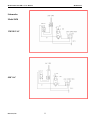
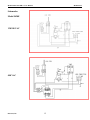
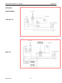
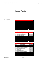
1
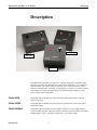
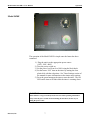
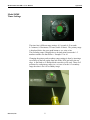
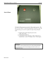
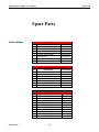
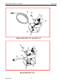
Model 5420 User’s Manual
Publication #: 107399-001 Rev. 1
May 2005
Another quality product from:
7128 Shady Oak Road, Eden Prairie, MN 55344
Phone: (952) 949-9009
Fax: (952) 949-9559
E-mail: [email protected]
www.researchinc.com
Dear Valued Customer:
Thank you for purchasing a Model 5420 ControlIR® power controller. We believe it is the finest power controller
of its type and are confident you will think so also.
This instruction manual has been carefully prepared to ensure you will be able to easily install and operate the
Model 5420 power controller and to fully realize all its inherent capabilities. We invite your comments as well as
any issues you may have regarding this manual or the Model 5420.
Requirement
Appropriate Contact
Additional information regarding application
of the Model 5420 system or other Research Inc.
products.
Your local sales representative.
Ordering additional Research Inc. products or Manuals.
Your local sales representative
or
Research, Inc. Customer Service (952) 949-9009
Technical assistance and training.
Research Inc. Factory Service
(952) 949-9009
Once again, let us welcome you to the growing family of Research Inc. customers. We look forward to working
with you in the future.
Sincerely,
Terry Nigon
Terry Nigon
President
Research Inc.
Model 5420 ControlIRTM User Manual
Section
Contents
Page
SAFETY
1
DESCRIPTION
2
3
Dimensions
INSTALLATION
Load Wiring Connections
Control Wiring Connections 5420mA
4
5
OPERATING INSTRUCTIONS
Model 5420
Model 5420E
Timer Settings
Model 5420mA
MAINTENANCE AND
TROUBLE SHOOTING
Schematics Model 5420
Schematics Model 5420E
Schematics Model 5420mA
6
7
8
9
10
11
12
13
SPARE PARTS LIST
Model 5420
Model 5420E
Model 5420mA
Exploded Parts View
14
15
16
17
Model 5420 ControlIRTM User Manual
Safety
Safety
General
Electrical
Safety
The Model 5420 Power Controller is designed for safe operation. Nevertheless,
installation, maintenance, and operation of the heater can be dangerous for a careless
operator or maintenance person. For your safety and the safety of others, read the
instructions in this manual and follow these warnings to help prevent accident or injury.
There is a danger of electrical shock when servicing this power controller or the attached
heating unit. Always disconnect the power cord when servicing the power controller or
the heating unit. Never operate the 5420 power controller with the cover removed or with
the heating unit cover removed. The covers have been design to protect the operator
from the high voltage present inside the unit.
WARNING!
Always disconnect the power cord when servicing the power controller or the
connected heater.
WARNING!
NEVER operate the power controller with the cover removed or the heater cover
removed.
Heater
Safety
The heating unit connected to the 5420 also requires special safety precautions. Parts of
the various heating units may exceed 500°F (260°C). Contact with the lamps, reflector, or
metal parts near the lamps can cause severe burns.
INFRARED RADIATION - CAUTION! Continuous exposure to highintensity infrared radiation at close proximity could be harmful to eyes or skin. Although
infrared lamps emit negligible ultra violet electromagnetic radiation, harmful burns can
still result if an operator is in close contact with lamps being operated at high intensity.
Because of the brilliant light emitted by infrared lamps at full intensity, it is recommended
that eyes be shielded from the glare if observing the lamps for an extended period of time.
Use suitable shaded lenses or dark glasses.
Research Inc.
1
Model 5420 ControlIRTM User Manual
Description
Description
Model 5420mA
Model 5420E
Model 5420E
Model 5420
The Model 5420 ControlIR is a 15 amp power controller designed to control the voltage
supplied to one of the many Research Inc. single lamp infrared heaters. It is available for
120, 240 and 480 volt control with an 8 foot power cord. Control features are either: a
manually set potentiometer, a manually set potentiometer with timer, or a 4-20mA external
control signal. The 5420 uses a phase angle fired Solid State Relay (SSR) to provide
precise voltage control to the heater.
Model 5420
Configured with an ON/OFF power switch and a one turn potentiometer to adjust the
voltage to the heater.
Model 5420E
Configured with an ON/OFF power switch, one turn potentiometer, and a timer with an
integral start switch.
Model 5420mA
Configured with an ON/OFF power switch and a connector for a user supplied remote
4-20 mA command signal. The output voltage to the heater increases linearly to the input
milliamp signal. (4 mA = 0% output voltage, 8mA = 25% output voltage)
Research, Inc.
2
Model 5420 ControlIRTM User Manual
Description
Dimensions
120 and 240 VAC
Model 5420
Model 5420E
Model 5420mA
7.06
120 AND 240 VAC
5420
8.13
4.72
480 VAC
Model 5420
Model 5420E
Model 5420mA
7.06
480 VAC
5420
10.06
Research, Inc.
3
4.72
Model 5420 ControlIRTM User Manual
Installation
Installation
Load Wiring
Connections
Research, Inc.
Connect the load wiring as follows:
1. Unplug the Model 5420 from the power source.
2. Remove the 4 screws that secure the cover to the base.
2 of the screws are on the back of the 5420 where the cord
exits the base and the other 2 are on the bottom next to the
front feet.
3. Carefully lift the cover up and tilt toward the front of the
unit. Note: There are wires that connect the components on
the cover to the components on the base.
4. Strip the insulation back on the heater wires ¼ inch.
5. Insert the wire from the heater through the strain relief.
6. Connect the heater wires to the LOAD CONNECTION
terminal block. Many of Research Inc. heaters use a High
Temperature Teflon wire that gets connected as follows:
Black – L1
White – L2
Red - GND
7. Finish the installation by tightening the strain relief around
the heater wires and installing the cover back on the base
with the 4 screws. DO NOT OPERATE WITHOUT
COVER PROPERLY INSTALLED.
4
Model 5420 ControlIRTM User Manual
Model 5420mA
Control Wiring
Installation
To connect the wires for the 4-20mA input on the Model 5420mA
unit follow these steps:
1.) Remove the 90° connector from the top of the 5420mA.
2.) Remove the (1) larger screw to take the connector apart.
3.) Install wires through the rubber strain relief on the top half of
the connector. Loosen the 2 screws of the cable clamp and
slide the cable through.
4.) Strip the wires and solder into pins 1 and 3. Pin 1 is + pin 3
is -.
5.) Reassemble the connector when complete, tightening the
cable clamp when complete.
+
Research, Inc.
5
-
Model 5420 ControlIRTM User Manual
Operation
Operation
Model 5420
The operation of the basic Model 5420 is simple once the heater has been
connected.
1.) Plug the unit in to the appropriate power source.
(120V, 240V, 480V)
2.) Turn the power switch on.
3.) Set the power level from 0 to 100% using the potentiometer
(black knob).
WARNING!
Infrared heaters can get extremely hot; do not leave them operating unattended.
Always turn the power switch off when shutting the unit down, do not rely on
setting the power to 0%.
Research, Inc.
6
Model 5420 ControlIRTM User Manual
Operation
Model 5420E
The operation of the Model 5420E is simple once the heater has been
connected.
1.) Plug the unit in to the appropriate power source.
(120V, 240V, 480V)
2.) Turn the power switch on.
3.) Set the power level from 0 to 100% using the black knob.
4.) Set the heater “ON” time on the timer by turning the clear
plastic dial with the red pointer. See Timer Settings section of
the manual for more information on the timers range settings.
5.) Press the green button on the timer to start the timer. The red
LED on the timer will flash while the timer is counting down.
WARNING!
Infrared heaters can get extremely hot; do not leave them operating unattended.
Always turn the power switch off when shutting the unit down, do not rely on
setting the power to 0%.
Research, Inc.
7
Model 5420 ControlIRTM User Manual
Operation
Model 5420E
Timer Settings
The timer has 6 different range settings: 0-5 seconds, 0-50 seconds
0-5 minutes, 0-50 minutes, 0-5 hours, and 0-50 hours. The primary range
is displayed below the green push button as: sec, min, or hrs.
The secondary range is displayed as a decimal point between the 1-5
numbers and the zero that follows. Example 1.0 or 10
Changing the primary and secondary range settings is done by inserting a
screwdriver in the hole on the front side of the 5420 just below the top
edge. A flat blade or #2 Philips blade screwdriver will work. There are 2
positions for each primary range (sec, sec) one is for the 0-5 secondary
range the other is for 0-50 secondary range.
Research, Inc.
8
Model 5420 ControlIRTM User Manual
Operation
Model 5420mA
The Model 5420mA requires an external 4-20mA signal to operate. This
unit will work with PLC’s and other programmable controllers to start and
stop the heating cycle as well as regulate the output voltage during the
cycle.
1.) Plug the unit in to the appropriate power source.
(120V, 240V, 480V)
2.) Turn the power switch on.
3.) Set the power level by supplying a 4-20mA signal from an
external source. (4 mA = 0% output, 20 mA = 100% output)
WARNING!
Infrared heaters can get extremely hot; do not leave them operating unattended.
Always turn the power switch off when shutting the unit down, do not rely on
setting the power to 0%.
Research, Inc.
9
Model 5420 ControlIRTM User Manual
Maintenance
Maintenance and
Trouble Shooting
Maintenance
No routine maintenance is required. The 5420 should be kept clean and
dry. If cleaning is required, unplug unit before cleaning.
Troubleshooting
Troubleshooting should be done by Qualified Personnel especially if the
5420 needs to be opened up.
SYMPTON
ACTION
Heater will not turn on.
- unit is plugged into an energized receptacle
- on/off switch is in the ‘On’ position.
- On 5420 and 5420E versions with
potentiometer control, verify control is not
set to 0.
- On 5420E make sure the timer is not set to
0 when pressing the green button,
additionally the red LED should be flashing
as the timer counts down.
- Heater properly connected to the 5420.
- Lamp burned out in the heater.
- 480 volt 5420E and 5420mA check fuses.
Heater will not turn off.
- Shorted SCR unit always runs at 100%
power. Can be checked: with unit
unplugged, open unit disconnect heater
wires and put an ohm meter across L1 and
L2 if it reads 0 or a small value, the SCR is
defective.
- On the 5420E check for the correct time
range, and LED flashing.
Research, Inc.
10
Model 5420 ControlIRTM User Manual
Maintenance
Schematics
Model 5420
120/240 VAC
480 VAC
Research, Inc.
11
Model 5420 ControlIRTM User Manual
Maintenance
Schematics
Model 5420E
120/240 VAC
480 VAC
Research, Inc.
12
Model 5420 ControlIRTM User Manual
Maintenance
Schematics
Model 5420mA
120/240 VAC
480 VAC
Research, Inc.
13
Model 5420 ControlIRTM User Manual
Spare Parts
Spare Parts
Model 5420
Model 5420-120 Replacement Parts
Item
Description
Part Number
1 150 k Ohm Potentiometer
067156-003
2 Solid State Relay Kit
107593-001
3 Two Position Rocker Switch
106820-003
4 Knob with White Pointer
055770-001
5 Terminal Strip
107353-001
6 Line Cord and Plug
086822-001
Model 5420-240 Replacement Parts
Item
Description
Part Number
1 1 Meg Ohm Potentiometer
067156-001
2 Solid State Relay Kit
107593-002
3 Two Position Rocker Switch
106820-003
4 Knob with White Pointer
055770-001
5 Terminal Strip
107353-001
6 Line Cord and Plug
106821-003
Model 5420-480 Replacement Parts
Item
Description
Part Number
1 1 Meg Ohm Potentiometer
067156-001
2 Solid State Relay Kit
107593-003
3 480 VAC/20 amp 2 Pole Switch
107406-001
4 Knob with White Pointer
055770-001
5 Terminal Strip
107353-001
6 Line Cord and Plug
103570-002
8 Black Switch Handle
107406-002
Research, Inc.
14
Model 5420 ControlIRTM User Manual
Spare Parts
Spare Parts
Model 5420E
Model 5420E-120 Replacement Parts
Item
Description
Part Number
1 150 k Ohm Potentiometer
067156-003
2 Solid State Relay Kit
107593-001
3 Two Position Rocker Switch
106820-003
4 Knob with White Pointer
055770-001
5 Terminal Strip
107353-001
6 Line Cord and Plug
086822-001
7 Interval Timer with Push Button
107407-001
Model 5420E-240 Replacement Parts
Item
Description
Part Number
1 150 k Ohm Potentiometer
067156-001
2 Solid State Relay Kit
107593-002
3 Two Position Rocker Switch
106820-003
4 Knob with White Pointer
055770-001
5 Terminal Strip
107353-001
6 Line Cord and Plug
106821-003
7 Interval Timer with Push Button
107407-001
Model 5420E-480 Replacement Parts
Item
Description
Part Number
1 1 Meg Ohm Potentiometer
067156-001
2 Solid State Relay Kit
107593-003
3 480 VAC/20 amp 2 Pole Switch
107406-001
4 Knob with White Pointer
055770-001
5 Terminal Strip
107353-001
6 Line Cord and Plug
103570-002
7 Interval Timer with Push Button
107407-001
8 Black Switch Handle
107406-002
9 .3 amp 600 volt Time Delay Fuse
086445-002
11 Transformer 25 VA
099390-001
Research, Inc.
15
Model 5420 ControlIRTM User Manual
Spare Parts
Spare Parts
Model 5420mA
Model 5420ma-120 Replacement Parts
Item
Description
Part Number
1 150 k Ohm Potentiometer
067156-003
2 Solid State Relay Kit
107593-004
3 Two Position Rocker Switch
106820-003
4 Knob with White Pointer
055770-001
5 Terminal Strip
107353-001
6 Line Cord and Plug
086822-001
10 4-20 mA Receptacle
083618-002
Item
1
2
3
4
5
6
10
Model 5420ma-240 Replacement Parts
Description
Part Number
1 Meg Ohm Potentiometer
067156-001
Solid State Relay Kit
107593-004
Two Position Rocker Switch
106820-003
Knob with White Pointer
055770-001
Terminal Strip
107353-001
Line Cord and Plug
106821-003
4-20 mA Receptacle
083618-002
Model 5420ma-480 Replacement Parts
Item
Description
Part Number
1 1 Meg Ohm Potentiometer
067156-001
2 Solid State Relay Kit
107593-005
3 480 VAC/20 amp 2 Pole Switch
107406-001
4 Knob with White Pointer
055770-001
5 Terminal Strip
107353-001
6 Line Cord and Plug
103570-002
8 Black Switch Handle
107406-002
9 .3 amp 600 volt Time Delay Fuse
086445-002
10 4-20 mA Receptacle
083618-002
11 Transformer 25VA
099390-001
Research, Inc.
16
Model 5420 ControlIRTM User Manual
Spare Parts
6
10
3
4
1
7
5
2
Model 5420 120 VAC and 240 VAC
10
4
8
1
3
7
9
6
5
2
Model 5420 480 VAC
Research, Inc.
17