1
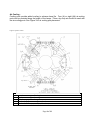
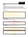
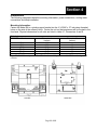
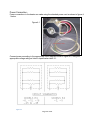
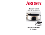
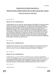
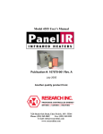
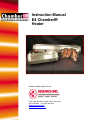
Instruction Manual
E4 ChamberIR
Heater
Another quality product from:
7128 Shady Oak Road • Eden Prairie, MN 55344
(952) 949-9009 Fax (952) 949-9559
www.researchinc.com
[email protected]
Contents
Contents
Contents ................................................................................................................................................ 2 Introduction .................................................................................................................................................. 4 Description ............................................................................................................................................... 4 Benefits ..................................................................................................................................................... 4 Applications ............................................................................................................................................ 5 Specifications ............................................................................................................................................... 6 General – .................................................................................................................................................. 6 Options and Accessories ........................................................................................................................ 7 Lamps - ................................................................................................................................................. 7 Quartz Liner - ....................................................................................................................................... 7 Observation Window - ......................................................................................................................... 7 Purging Ports - ...................................................................................................................................... 7 Air Cooling - ........................................................................................................................................ 8 Safety ............................................................................................................................................................ 9 General .................................................................................................................................................... 9 Infrared Radiation - .............................................................................................................................. 9 High Temperatures - ............................................................................................................................. 9 Electrical Safety - ................................................................................................................................. 9 Fire Safety - ........................................................................................................................................ 10 Installation .................................................................................................................................................. 11 Mounting Information - ...................................................................................................................... 11 Power Connection - ................................................................................................................................ 12 Cooling Water Connections - ................................................................................................................. 13 Lamp Installation (E4-5, 10, 16, 25 and 38) ....................................................................................... 13 Lamp Installation (E4-02, -06) ............................................................................................................ 14 Operation .................................................................................................................................................... 16 General ................................................................................................................................................... 16 Principals of Infrared Heating ................................................................................................................ 16 Operating Procedures ............................................................................................................................. 17 Maintenance ............................................................................................................................................... 18 Cleaning Procedures ............................................................................................................................... 18 Page 2 of 19
Page 3 of 19
Section 1
Introduction
The Model E4 elliptical chamber is designed for rapid heating of small size continuous materials
such as tube, cable, and wire with an outer diameter from 0.25 to 0.125 inches in diameter. It
may also be used as a high temperature furnace in test applications. The E4 is available in
seven different lengths. Typical applications for these heaters
include:
•
•
•
•
•
•
Curing small-diameter silicone tubing
Re-glossing small-diameter plastic tubing
Burning lubricant off extruded wire
Curing coatings or adhesives on wire or cable
Drying water from wire or cable
Preheat wire or cable
Description
The Model E4 focuses high-density infrared energy, generated by 'T3-style', halogen lamps,
onto a cylindrically shaped target area. The heater is hinged so it can open and close in a
clamshell style, for easy access.
Reflectors
Four elliptical reflectors (see Figure 1) focus the infrared
energy supplied by T3 lamps toward the heater center axis.
The reflectors are constructed from aluminum polished to a
specular finish and are available in heated lengths of 2, 5, 6,
10, 16, 25, and 38 inches (51,127, 152, 254, 406, 635, and
965 mm).
Figure 1: E4 Reflector
Configuration
Lamps
Included are four high intensity, short wave, 'T3-style', infrared
lamps. The tungsten emitter in the lamps has an operating
temperature of 2500 °K with a spectral energy peak
wavelength of 1.15 microns. Each Model E4 requires four lamps to operate. The lamps are
included with the Model E4.
Water Cooling
The Model E4 requires an external water-cooling supply to cool the reflectors. Refer to table 1
for flow rates depending upon model.
Benefits
Fast
T3 lamps heat up and cool down instantly in response to power control signals. They reach 90
percent of full operating temperature within three seconds from a cold start. The radiant energy
Page 4 of 19
dissipates to ten percent within five seconds after power is removed. The instant on/off feature
offers a great number of benefits to the user including reduced warm up and cool down times.
Focused T3 lamps have a small filament, which allows the energy to be focused towards a target. By
focusing the IR, the concentration of heat is greatly increased, which allows small targets to see
more thermal energy and allows higher process line speeds.
Figure 2 – Silicone Jacketed Wire Heating
300
250
Temp (ºC)
Controlled The ability to control the direction of the infrared heat,
along with rapid response, allows higher heat transfer
rates than with other infrared and convection systems.
Figure 2 shows the heating of a silicone-jacketed wire.
Using an E4, the wire is heated to curing temperature
in several seconds, as compared to 2 to 5 times longer
with other systems.
200
150
100
50
0
0
1
2
3
4
5
Time (sec)
Applications
0.1” (2.5 mm) OD Silicone Wire - 275º C
Cure
Low Temperature ApplicationsE4-25 with 2500-watt lamps
Most pre- and post- plastics and rubber extrusion
applications are low temperature (under 400 °C). Under these conditions, it is only necessary
to provide water-cooling to the reflectors to allow the heaters to run continuously. The
recommended maximum product diameter in these applications is 0.25 inch (6 mm). The
heater will accommodate product size up to 2.5 inches in OD, however the heating will not be
uniform around the circumference if the OD is greater than 0.25 inch (6 mm). Refer to the
Model 4069 product data sheet for uniform heating of larger materials.
High Temperature Applications The Model E4 may also be operated as a high temperature furnace. Transient product
temperatures to 2000°F (1100°C) and continuous product temperatures to 1500°F (815°C) can
be achieved with the Model E4. Air-cooling options (A/AA) are recommended if operated in this
mode.
Specimen Sizes The Chamber will accommodate specimens up to 2.50 inches in diameter. When operating at
high heat flux outputs (lamp rated voltage or greater) the specimen should be no less than 1/8th
inch in diameter and of a length equal to lamp lighted length, to prevent lamp damage.
Specimen Temperature Transient temperature up to 3000˚F can be reached and higher specimen temperatures may be
reached but at a risk of premature lamp failure. A continuous set point of up to 2000˚F may be
achevied. Shorter periods at constant temperature apply as specimen approaches maximum.
For highest specimen temperatures and heating rates, specimen surface should be blackened
to increase the absorptive characteristics.
Page 5 of 19
Section 2
Specifications
General –
Refer to the table 2-1 below for general specifications and ratings on the various models of E4.
Table 2-1
Model No:
Weight (lbs) Lamp P/N Lighted Length (in) Lamp Rated Voltage Current (Amps) Rated Power (KW) Water Flow (gpm) Operating Voltage E4-2
E4-5
E4-6
E4-10
13 057550‐002 057550‐003 2.37 18 057541‐001 5.0 22 057550‐004 6.75 27 057544‐002 057544‐005 10.00 120 120 120 240 240 240 16.67 33.33 16.67 25.00 16.67 33.33 2.0 4.0 2.0 6.0 4.0 8.0 .25 .49 .25 .74 .49 .98 240 240 240 240 240 240 Model
No:
Weight (lbs) Lamp P/N Lighted Length (in) Lamp Rated Voltage Current (Amps) E4-16
E4-25
38 057541‐004 057541‐008* 16.0 54 057549‐001 25.0 240 240 480 26.67 50.0 20.83 Rated Power (KW) 6.4 Water Flow (gpm) Operating Voltage .79 1.47 240 240 12.0 10.0 E4-38
057544‐008* 77 057549‐002 38.0 600 570 33.33 26.67 (29.55 @ 480V) (24.30 @ 480V)
20.0 15.2 (14.18 @ 480V)
(11.67 @ 480V)
1.23 1.74 1.43 480 480 480 * Indicates Horizontal Operation Only
Page 6 of 19
Options and Accessories
Lamps Lamps for the Model E4 are included with the heater. Table 2-2 displays available lamps for
replacement ordering.
Table 2-2: Lamps
Heated
Model (P/N)
Length
Volts
Watts
057550-002
2 Inches
120
500
057550-003
2 Inches
120
1000
057541-001
5 Inches
120
500
057550-004
6 Inches
120
1500
057544-002
10 Inches
240
1000
057544-005
10 Inches
240
2000
057541-004
16 Inches
240
1600
057541-008
16 Inches
240
3000
057541-005
25 Inches
480
2500
057549-001
25 Inches
480
2500
057544-008
25 Inches
600
5000
057541-006
38 Inches
570
3800
057549-002
38 Inches
570
3800
(*) Standard lamp that ships in heater
(**) Lamps are for Horizontal Operation Only
Lamp Description
Q500T3/CL
Q1000T3/4CL (*)
500T3/CL (*)
Q1500T3/CL (*)
1000/T3/2CL/HT
2000/T3/CL/HT (*)
1600T3/CL
3000T3/CL (*) (**)
2500T3/CL (**)
2500T3/VB/CL (*)
5MT3/1CL/HT (**)
3800T3/CL (**)
3800T3/VB/CL (*)
Quartz Liner A quartz liner can be provided to protect the reflectors in the heater from contaminants, to
maintain the reflectors at their maximum efficiency. It has a 2.24 inch (57 mm) outer diameter
and a 2.09 inch (53 mm) inner diameter.
Observation Window A 0.5 inch diameter window (W) with a quartz cover can be provided in the center of the
chamber side wall, to permit product viewing. With the quartz cover removed, product
temperature can be measured with a suitable optical pyrometer. The observation window is not
available on models ordered with four purging ports. See Figure 3 for Window placement.
Purging Ports Purging ports can be provided on two (P) or four (PP) opposing sides of the chamber wall. This
feature allows the heating environment to be force-cooled or inert gas-purged. Purging ports
will not function with a quartz liner installed. See Figure 3 for purge port placement.
Page 7 of 19
Air Cooling Cooling ports provide added cooling to enhance lamp life. Four (A) or eight (AA) air-cooling
ports can be provided along the length of the lamps. Clean, dry shop air should be used with
the air-cooling ports. See Figure 3 for air cooling port placement.
Figure 3 Option Location
Option Codes (additional machining required)
A Four port Air Cooling (lamp cooling)
AA Eight port Air Cooling (lamp cooling)
P Two port purge (process cooling/atmosphere)
PP Four port purge (process cooling/atmosphere)
W Observation Window (Pyromter port, ½” diameter)
Page 8 of 19
Section 3
Safety
General
The E4 ChamberIR Heater is designed for safe operation. Nevertheless, installation,
maintenance and operation of the heater can be dangerous for a careless operator or
maintenance person. For your safety and the safety of others, please read the instructions in
this INSTRUCTION MANUAL and follow these safety practices that will help to prevent accident
or injury.
Infrared Radiation !CAUTION!
Continuous exposure to high intensity infrared radiation at close proximity could be
harmful to eyes or skin. Although infrared lamps are not emitting ultra violet
electromagnetic radiation, harmful burns could still result if an operator is in close
contact with lamps being operated at high intensity.
Because of the brilliant light emitted by infrared lamps at full intensity, it is
recommended that the eyes be shielded from the glare if observing the lamps or radiant
heat chamber for an extended period of time. Use suitable shaded lenses or dark
glasses.
High Temperatures Parts of the heater may exceed 500°F (260°C). Contact with the lamps, reflectors, or metal
parts near the lamps may cause severe BURNS.
!WARNING!
NEVER place hands under the heating elements.
ALWAYS allow heating element to cool at least 5 minutes before touching the lamps or
adjacent parts.
Electrical Safety There is danger of electrical shock when servicing the heater.
!CAUTION!
Observe that all applicable local and national electrical codes are met and a safe
electrical ground system is installed before
attempting to operate the heater. Refer to
WARNING!
the Section 4 for proper installation procedures.
ALWAYS disconnect the external power lines prior to servicing the heater.
ALWAYS disconnect the power lines AND any optional interlock circuits before installing
or changing lamps.
NEVER operate the heater with the heater end covers removed.
Page 9 of 19
Fire Safety 1. Obey the same fire-safety rules you observe when you work with hot plates, high
intensity infrared heaters, propane or acetylene torches, soldering irons, and other
equipment that operates at high temperatures.
2. Remove all solids, liquids, and gases that burn easily from the area around the heater.
3. Know where the nearest fire extinguisher is located and how to use it.
4. Know how to put out fire from all the types of material near the Model E4 Heater.
Page 10 of 19
Section 4
Installation
The following paragraphs describe mounting information, power connections, cooling water
connections and lamp installation.
Mounting Information Fasten the Model E4 to a sturdy support bracket via the 4 ¼-20NC x .37 inch deep threaded
holes on the side of the reflector block. Center the unit so that specimens will be located in the
focal axis. Physical dimensions for all units are listed in table 4-1, Dimensions A and B.
Table 4-1
Model Number
E4-2
E4-5
E4-6
E4-10
E4-16
E4-25
Dimension A
(inches)
2.50
5.50
7.40
10.50
16.50
25.50
Dimension B
(inches)
--3.0
3.0
5.0
5.0
5.0
Note: The E4-02 has only two ¼-20 x .37 holes that are 1” apart, centered 1.25” from the edge of the
reflector
Page 11 of 19
Power Connection Power connections to the heater are made using the attached power cord as shown in figure 41 below.
Figure 4-1
Connect power according to the appropriate circuit diagram shown in figure 4-2, using the
appropriate voltage rating as listed in specification table 2-1.
Figure 4-2
Page 12 of 19
Cooling Water Connections 1/8” NPT tapped holes are provided for lamp reflector cooling water connections. Clean water
at 100˚F maximum, less than 100 psi must be supplied to the unit, at flow rates indicated in
specification table 2-1 for the appropriate sized Model E4 heater. Deionized water is preffered
Connect cooling water lines to water inlet and outlet ports such that water flows thru both halves
of the unit at minimum flow rates given in specification table 2-1.
!CAUTION!
Cooling Water exit temperatures not to exceed 150˚ F
NOTE
Cooling Flow is optional during short/ transient heating tests where reflector body
temperatures will not exceed 350˚F
Lamp Installation (E4-5, 10, 16, 25 and 38)
NOTE
The 2000 watt per inch lamps (2000T3 and 5MT3) should be used for intermittent operation
only with 50% duty cycle at rated voltage and a maximum on-time of three minutes, or if it is
determined that the exit water temperature remains at 150˚F or less during experimental runs,
higher duty cycles or maximum on-times may be increased accordingly. At no time should the
reflector body exceed 350˚F.
1. Remove power to the heater. Turning down the voltage to 0 VAC on a SCR controller does
not remove power from the lamps.
2. Remove both covers for the heater half that has the burned out lamp.
3. With a volt meter check to insure voltage is removed from the heater.
4. Loosen the screws on the bus bar that the lamp lead wires are wrapped around and remove wires
from the screws.
Page 13 of 19
5. Remove the lamp.
6. Install a new lamp and center the lamp in the heater. Wrap the lamp lead wires around the screws
as shown in the picture. Tighten bus bar screws and trim off the excess wire.
7. Using a meter Ohm between the bus bar and ground checking for a short.
8. Install the lamp end covers.
NOTE:
Should lamp surfaces become contaminated with smoke,
dust, fingerprints or other foreign material, wipe clean before continuing
operation or installation
Lamp Installation (E4-02, -06)
1. Remove power to the heater. Turning down the voltage to 0 VAC on a SCR controller does
not remove power from the lamps.
2. Remove both covers for the heater half that has the burned out lamp.
3. With a volt meter check to insure voltage is removed from the heater.
4. Locate the leaf spring style contact and remove the screw from the leaf spring that is closest to the
lamp. Loosen the remaining screw in the leaf spring so that it can be turned out of the way of the
lamp.
Page 14 of 19
5. Remove the lamp. Inspect the lamp contact points on both ends of the heater for damage.
Replace as needed.
6. Install a new lamp and install the screw removed from the lamp contact in step #2. Tighten both
screws.
7. Make sure the metal contacts of the lamp are in contact with the button contacts of the heater.
8. Install the lamp end covers
Page 15 of 19
9.
Section 5
Operation
General
The following paragraphs describe the general principles of Infrared Heating and the detailed
operation procedures for the Model E4 Quad Elliptical Heating Chamber.
Principals of Infrared Heating
General Heat energy from a resistance element is transformed into infrared radiant energy at the
surface of the heating element. Infrared radiant energy passes through the air (without heating
it) to the receiving object where it is absorbed and converted back into heat energy. The
receiving object then heats up. (Actually in an infrared installation, the air does heat up, but this
is due to convection heating from the work piece, reflector and lamp walls)
A substance ideally transparent to infrared energy converts none of the radiant energy to heat,
since the infrared energy passes through the substance. A surface with high infrared
absorptance characteristics converts almost all the infrared energy striking it into heat energy. A
surface having a low infrared absorptance characteristics reflect most of the radiant energy
striking it.
All materials absorb some infrared energy, and usually their absorptivity can be increased by
coating the surface with a material which is a good infrared absorber.
Temperature Maximum workpiece temperature is dependent on:
1. Heat Input Factors: Radiation to workpiece, area of workpiece being irradiated, and
absorptivity of workpiece.
2. Heat Loss Factors: Conduction to unheated masses, convection losses and radiation to
non-reflective surface.
Highest workpiece temperatures are attained when heat input factors are high, and heat loss
factors are held to a minimum. Overall efficiency is improved by blackening the heated side and
insulating the unheated side of the workpiece.
Workpiece For highest efficiency, the workpiece should have a dark, non-reflective (high absorptance to
infrared energy) surface; The workpiece should be located as close as possible to the focal line
of the heater.
Instrumentation Workpiece temperature can be monitored by a thermocouple attached directly to the specimen.
For measuring temperature on a moving web workpiece an optical pyrometer may be used.
Power Controls Page 16 of 19
To control rapid rates in high response application a closed loop temperature controller should
be used. To reduce excessive inrush current, always preheat lamp filament for at least ½
second before applying full voltage.
Operating Procedures
The following procedures are used to operate the Model E4 Quad Elliptical Heating chamber.
Warning
Prior to operation, ensure all installation procedures are
performed as described in section 4, Installation
1. Unlock hinge fastener and open up unit
2. Center and locate specimen within Heating Chamber opening, and if desired, attach
thermocouples to specimen.
3. Close unit and lock hinge fastener
4. Turn on coolant water. Check for leaks and obstructions in coolant flow lines.
5. Select appropriate voltage level on power controller or input power source and switch
power to On. (See table 2-1 for input voltage ratings for lamps used in appropriate model
E4)
6. Control heating rate for desired time interval and switch power to off.
7. Allow heat to dissipate from heating chamber and specimen, then open unit and remove
specimen.
8. Visually inspect lamps and interior reflector surfaces of heating chamber for foreign
matter and contamination. Clean (if required) before installing another specimen. (Refer
to section 5, Maintenance, for proper cleaning procedures.)
Maximum specimen temperature depends on:
a) Conduction and convection heat loss
b) Surface area;
c) Reflectivity of specimen. Up to 3000˚F for short periods, i.e., a few seconds, is permissible
where above parameters are relatively small.
Warning
Do not exceed 2000˚F continuous specimen setpoint temperatures
Page 17 of 19
Section 6
Maintenance
Periodic inspection and removal of dirt and contaminants will ensure that equipment can be
operated safely.
In dirty environments or heating operations the lamps & reflectors may become contaminated
with smoke, dust, fingerprints or other foreign matter. When this occurs it is recommended that
the lamp be cleaned. Doing so will extend the life of the lamp and improve the heater’s overall
performance. Use the following procedure:
!WARNING!
Disconnect the power cable from the power source and
allow the heater to cool before continuing.
!CAUTION!
Wear soft, clean, oil-free flannel or plastic gloves when handling
quartz lamps. If skin oils come in contact with the quartz tube, the
lamp will fail prematurely.
Cleaning Procedures
Lamp Surfaces With a soft, dry cloth or tissue, wipe the residue from the lamps. Household strength ammonia
can be used to clean the lamps if necessary.
Reflector Surfaces With a soft, dry cloth or tissue, wipe the residue from the lamps. Household strength ammonia
can be used to clean the lamps if necessary. In the event of high concentrations of
contaminants it may be necessary to disassemble the unit, clean, and repolish the reflector
surfaces to a specular finish. Contact Research Inc. Service for this.
Exterior Surfaces Periodic inspection for dirt and contaminations and a visual check of all water connections to
assure they are leak proof, will insure that equipment can be operated safely
Page 18 of 19