1
Radiocrafts
Embedded Wireless Solutions
RC1180-MBUS
Wireless M-Bus Multi-Mode RF Transceiver Module
(EN 13757-4:2005)
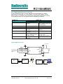
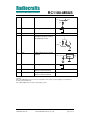
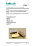
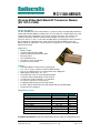
Product Description
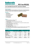
The RC1180-MBUS RF Transceiver Module is a compact surface-mounted high performance
module with embedded Wireless M-Bus protocol. The module has a UART interface for serial
communication and configuration, and a one-pin antenna connection. The module is precertified for operation under the European radio regulations for license-free use and
measures only 12.7 x 25.4 x 3.3 mm with shielding. When used with quarter-wave antennas a
line-of-sight range of 500-600 meter can be achieved. The RC1180-MBUS meets the
Wireless M-Bus specification S, T and R2 modes, and operates in 12 channels in the 868
MHz frequency band.
Applications
• Wireless M-Bus
• Automatic Meter Reading (AMR)
• Advanced Metering Infrastructure (AMI)
• Electricity meters
• Gas and Water meters
• Heat meters, Heat cost allocators
• Readers and concentrators
Features
• Embedded Wireless M-Bus protocol supporting EN 13757-4:2005 mode S, T and R2
• 12.7 x 25.4 x 3.3 mm compact module for SMD mounting
• Easy to use UART interface for communication and configuration
• Wide supply voltage range, 2.0 – 3.6 V
• Ultra low power modes for extended battery lifetime
• 2 channels (868.3, 868.95 MHz) in mode S and T
• 10 channels in mode R2 (868.03 + n x 0.06 MHz)
• No external components except antenna
• Configurable Manufacturer ID and serial number
• Conforms with EU R&TTE directive (EN 300 220, EN 301 489, EN 60950)
• Designed for EX compliance
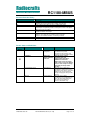
Quick Reference Data
Parameter
Frequency bands
Number of channels
Data rate
Max output power
Sensitivity, R/S/T
Supply voltage
Current consumption, RX / TX
Current consumption, SLEEP
Temperature range (S and T mode)
RC1180-MBUS
868.0 – 870.0
12
4.8, 32.768, 100
9
-106/-102/-101
2.0 – 3.6
24 / 37
Typ 0.3
-40 to +85
Unit
MHz
kchip/s
dBm
dBm
Volt
mA
uA
°C
PRELIMINARY INFORMATION. Specifications and information herein are subject to change without notice.
2008 Radiocrafts AS
RC1180-MBUS Data Sheet (rev. 2.00)
Page 1 of 16
Radiocrafts
Embedded Wireless Solutions
RC1180-MBUS
RC1180-MBUS Embedded Firmware Solutions
The RC1180-MBUS module is available with different embedded firmware solutions,
implementing specific feature sets. The hardware is the same for all solutions, and the
different feature sets available are listed in the table below. Detailed information on how to
use the different feature set is described in the RC1180-MBUS User Manual.
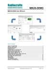
Feature List
Feature set
RC1180-MBUS2
Added features for NTA
8130 compliance (for use in
the Netherlands)
Master or Slave
Master or Slave
S1, S2, T1, T2, R2
S1, S2, T1, T2, R2
No, must be handled
AES-128 according to
externally
NTA8130
No, must be handled
Yes, according to NTA 8130
externally
No, receives any M-Bus
Master receives only
packet. Filtering must be
messages from
handled externally
installed/registered meters
No, must be handled
Yes, according to NTA 8131
externally
RC1180-MBUS1
Basic Wireless M-Bus
functions
General
Network role
Modes
Encryption
Installation mode
Filter function
Automatic acknowledge in T2
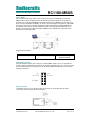
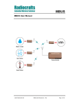
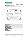
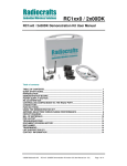
Typical application circuit
2.0 – 3.6 V
Optional
GND
RTS
CTS
CONFIG
TXD
RXD
GND
{
To host meter or
RS232/422/485
driver
RXD
Meter
TXD
RC1180-MBUS
(modem)
GND
VCC
RESET
NC
GND
RF
GND
RC1180-MBUS
(modem)
UART
2008 Radiocrafts AS
RC1180-MBUS Data Sheet (rev. 2.00)
Antenna
NC
NC
UART to:
RS232
RS485
USB
Ethernet
Page 2 of 16
Radiocrafts
RC1180-MBUS
Embedded Wireless Solutions
Quick Product Introduction
How do I transmit data?
Send your data to the RXD pin on the module. Use the UART format with settings (19200, 8,
1, N, no flow control). Up to 128 bytes are buffered in the module. The first byte of the
message should contain the message length. The module will transmit the data when the
whole packet is received.
How do I receive data?
Any received data packet with correct M-Bus format and check sums will be sent on the TXD
pin. Optionally the meter address (first M-Bus block) is added to the data string. The RSSI
value (received signal strength) can optionally be added to the message.
What about the antenna?
In most cases a simple quarter wavelength wire or a PCB track will do. Connect a piece of
wire to the RF pin with length corresponding to the quarter of a wavelength. For space limited
products, contact Radiocrafts and we will recommend the best antenna solution for your
application.
How do I change the M-Bus mode, RF channel or any other parameter?
To change configurable parameters, send one byte to the module with the value 0x00. This
will take the module into configuration mode. Special commands are then used to access the
configuration registers and test modes. Exit from configuration mode by sending the ‘X’
command. Parameters can be changed permanently and stored in non-volatile memory in the
module.
Wireless M-Bus Modem
The standard RC1180-MBUS module acts like a wireless M-Bus modem with a UART
interface. The embedded protocol transmits and receives the wireless M-Bus data packets
based on application messages from an external source (the meter or the concentrator). The
module automatically adds the Command field, the Manufacturer ID and the unique Address
based on parameters configured in the module. The UART data can easily be converted to
USB or RS485/232 to interface external equipment. The module is configured through its
UART interface using a simple command set. Configuration parameters are stored in nonvolatile memory. The module can be set in Sleep mode with very low current consumption,
and wake up on a UART command. The protocol for UART application messages (see MBUS
User Manual for details) is as follows:
From meter to module:
1 byte
1 byte
n bytes
Length
CI
APP_LAYER
From module to other (with meter address):
1 byte
1 byte
2 bytes
6 bytes
1 byte
n bytes
1 byte
Length
CI
APP_LAYER
RSSI (opt)
C
ManID
Address
From module to other (without meter address):
1 byte
1 byte
n bytes
1 byte
Length
RSSI (opt)
CI
APP_LAYER
Similar commands are available for configuration via the UART interface.
2008 Radiocrafts AS
RC1180-MBUS Data Sheet (rev. 2.00)
Page 3 of 16
Radiocrafts
Embedded Wireless Solutions
RC1180-MBUS
RF Frequency, Output Power Levels and Data Rates
The following table shows the available RF channels and their corresponding frequencies,
nominal output power levels and available data rates. The combination of frequency and data
rate is determined by the M-Bus mode. For R mode the RF channel selection must be
selected between 1-10.
Model
RF channel
RC1180- 1-10:
MBUS
fRF=868.03+(N-1)*0.06 MHz
where N is the channel number
11 (used in S and T2 mode):
fRF=868.300 MHz
Output power
1: -20 dBm
2: -10 dBm
3: 0 dBm
4: 5 dBm
5: 9 dBm
Data rate
1: 4.8 kchip/s
2: 32.768 kchip/s
3: 100 kchip/s
12 (used in T1 and T2 mode):
fRF=868.950 MHz
Factory setting: 1: 868.030 MHz
(apply for R mode only)
For more details on changing the RF channel, output power or M-Bus mode, refer to the
MBUS User Manual.
RSSI Reading
The module provide a digital Received Signal Strength Indicator (RSSI) through the ‘S’
command, or attached to the received messages. The RSSI value appended to a received
message is the signal strength of that received packet. The RSSI value is a 8 bit character
(one byte) indicating the current input signal strength or the signal strength of the received
message. The signal strength can be used as an indication of fading margin, or as a carrier
sense signal to avoid collisions.
The RSSI value increases with increased input signal strength in 0.5 dB steps. Input signal
strength is given by (typ.):
P = - RSSI / 2 [dBm]
2008 Radiocrafts AS
RC1180-MBUS Data Sheet (rev. 2.00)
Page 4 of 16
Radiocrafts
Embedded Wireless Solutions
RC1180-MBUS
Full wireless M-Bus application (optional custom specific version)
As an option, a full wireless M-Bus application layer can be integrated in the module based on
customer specification. In this case all the application layer protocol and timing will be
handled internally by the module. An S0 (1-pin) pulse interface and/or a serial interface can
be used to read out values from any meter. Since the protocol for reading out meter
information may differ from meter to meter, the embedded firmware is customized for each
different meter and application.
These are some of the features that can be used in a customized application:
• 4 kB EEPROM for storing meter data
• 32 kHz oscillator for real time clock time stamps
• AES-128 encryption
• Sleep timers
• Message acknowledgement and re-transmissions
• Digital I/O pins for tamper detection, alarms and installation
• A/D converter for analogue sensors
Please see chapter “Programming Interface” for a description of how to include a
programming connector in your PCB layout to be able to receive updated firmware code from
Radiocrafts in a pilot product phase.
One-Button Installation (optional custom specific version)
Due to the two-way transceiver capability of the RC1180-MBUS module, a simple and robust
installation procedure can be used even for S1 and T1 (one-way) operation modes.
In a full M-Bus application, the Radiocrafts unique “one-button” installation feature simplifies
the installation and reduces installation time substantially. Using an external push-button and
a LED connected to dedicated pins on the module, the installation procedure is very simple:
•
•
•
•
Press the install button on concentrator
Press the install button on meter
Wait 5 seconds for two way communication between meter and concentrator
See installation LED go on for OK installation (Blinking for error during installation)
Please contact Radiocrafts for custom specific requests.
2008 Radiocrafts AS
RC1180-MBUS Data Sheet (rev. 2.00)
Page 5 of 16
Radiocrafts
RC1180-MBUS
Embedded Wireless Solutions
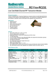
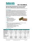
Block Diagram
2.0 - 3.6 V
8-bit MCU
Pulse input (option)
M-Bus Application
(option)
Wireless M-Bus
RF Tranceiver
UART interface
Wireless M-Bus
protocol
32 kHz
Real Time Clock
(option)
32 MHz
clock
4kB EEPROM
(option)
Circuit Description
The module contains a communication controller with embedded Wireless M-Bus protocol
software and a high performance RF transceiver. As an option the module can support a real
time clock oscillator and EEPROM memory.
The communication controller handles the radio packet protocol, the UART interface and
controls the RF transceiver. Data to be sent by the host is received at the RXD pin and
buffered in the communication controller. The data packet is then assembled with preamble,
start-of-frame delimited (SOF), manufacturer ID, unique address information and CRC check
sums before it is transmitted on RF.
The RF transceiver modulates the data to be transmitted on RF frequency, and demodulates
data that are received. Digital signal processing technology is used to enhance sensitivity and
selectivity.
Received data are checked for correct CRC by the communication controller. If no CRC
errors were detected, the data packet is sent to the host on the TXD line. The data format is
configurable, and optionally an RSSI value (signal strength of received packet) can be added
to the message.
The asynchronous UART interface consists of RXD and TXD. Optionally CTS or RTS can be
used for hardware handshake flow control.
When a 00h value is sent as the first byte (replacing the Length byte), or the CONFIG pin is
asserted, the module enters configuration mode and the communication controller interprets
data received on the RXD pin as configuration commands. There are commands to change
the radio channel, the output power, etc. Permanent changes of the configuration is also
possible and are then stored in internal non-volatile memory (Flash).
The supply voltage is connected to the VCC pin. The module contains an internal voltage
regulator for the RF transceiver and can therefore operate over a wide supply voltage range.
2008 Radiocrafts AS
RC1180-MBUS Data Sheet (rev. 2.00)
Page 6 of 16
Radiocrafts
RC1180-MBUS
Embedded Wireless Solutions
The module can be set in Sleep mode to reduce the power consumption to a minimum. The
module is then woken up by sending a FFh byte on the UART. Sleep mode can be entered by
sending a sleep command, or by configuring the module to always return to Sleep mode after
data transmission (S1 and T1 modes).
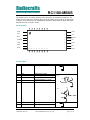
Pin Assignment
30
GND
29
28
27
26
25
24
23
1
14
GND
2
13
VCC
3
12
RESET
CONFIG
4
11
NC
TXD
5
10
GND
RXD
6
9
GND
7
8
CTS
RTS
15
16
17
18
19
20
21
RF
GND
22
Pin Description
Pin no Pin name
1
GND
Description
System ground
2
3
4
CTS
RTS
CONFIG
5
6
TXD
RXD
UART Clear to Send
UART Request to Send
Configuration Enable. Active low.
Should normally be set high
UART TX Data
UART RX Data
Equivalent circuit
GND
VCC
Input:
20k
VCC
Output:
7
8
GND
GND
2008 Radiocrafts AS
System ground
System ground
RC1180-MBUS Data Sheet (rev. 2.00)
GND
Page 7 of 16
Radiocrafts
Embedded Wireless Solutions
9
RF
RC1180-MBUS
RF I/O connection to antenna
RF
10k
10
GND
System ground
11
12
NC
RESET
Not connected
Main reset (active low). Should
normally be left open. Internal
100 kΩ pull-up resistor.
GND
VCC
12k
RESET
13
VCC
Supply voltage input. Internally
regulated.
1.8 V
VREG
VCC
2u2
14
GND
System ground
15-22
RESERVED
23-30
RESERVED
Test pins or pins reserved for
future use. Do not connect!
Test pins or pins reserved for
future use. Do not connect!
GND
Note 1: For UART communication the TXD and RXD are used for serial data, and CTS and RTS for flow control
(optional).
Note 2: The CONFIG pin can be used to enter configuration mode (change of default settings) as an alternative to
the 0x00 command. Active low.
Note 3: Other digital interfaces may be specified upon request.
2008 Radiocrafts AS
RC1180-MBUS Data Sheet (rev. 2.00)
Page 8 of 16
Radiocrafts
RC1180-MBUS
Embedded Wireless Solutions
Power Supply
Noisy external circuitry may under certain scenarios affect the transmitted signal on RC1180MBUS and precaution should be taken for EU R&TTE conformity. Example of circuits that can
generate noise on the RC1180-MBUS transmitted spectrum may be DC/DC converters and some
level converters like RS232 and RS485. To increase spectrum margin it is important to add an EMI
filter bead on the VCC pin of the RC11XX-RC232 module. Alternatively the RC1180-MBUS may
be powered form a separate voltage regulator. This will ensure that potential switching noise is
filtered out from the power supply to the RC1180-MBUS. A block diagram of a typical PC serial
port interface is illustrated below.
Suggested part numbers:
Component
EMI filter bead
Manufacturer
Murata
Part number
BLM11A102S, ordering code
BLM18xx102xN1D
Programming Interface
For future firmware updates and to change to a different MBUs feature set it is recommended to
include a 2x5 pins programming connector to the module programming pins. The connector should
be a 2.54 mm pitch pin-row (same pitch in both directions), SMD or through-hole version, with the
following connections:
GND
RC11xx Pin 20
Pin 12, RESET
1
2 To VCC
3
4 RC11xx Pin 19
7
Reset connection
To minimize effect of noise on the Reset-line, the Reset pin on the module (pin 12) must be
connected to external circuitry via an RC-network.
2008 Radiocrafts AS
RC1180-MBUS Data Sheet (rev. 2.00)
Page 9 of 16
Radiocrafts
Embedded Wireless Solutions
RC1180-MBUS
Antenna Connection
The antenna should be connected to the RF pin. The RF pin is matched to 50 Ohm. If the
antenna connector is placed away from the module at the motherboard, the track between the
RF pin and the connector should be a 50 Ohm transmission line.
On a two layer board made of FR4 the width of a microstrip transmission line should be 1.8
times the thickness of the board, assuming a dielectric constant of 4.8. The line should be run
at the top of the board, and the bottom side should be a ground plane.
Example: For a 1.6 mm thick FR4 board, the width of the trace on the top side should be 1.8 x
1.6 mm = 2.88 mm.
The simplest antenna to use is the quarter wave whip antenna. A quarter wave whip antenna
above a ground plane yields 37 Ohm impedance and a matching circuit for 50 Ohm are
usually not required.
A PCB antenna can be made as a copper track where the ground plane is removed on the
back side. The rest of the PCB board should have a ground plane as large as possible,
preferably as large as the antenna itself, to make it act as a counterweight to the antenna. If
the track is shorter than a quarter of a wavelength, the antenna should be matched to 50
ohms.
The lengths of a quarter wave antenna for different operational frequencies are given in the
table below.
Frequency
[MHz]
868
Length
[cm]
8.2
Regulatory Compliance Information
The use of RF frequencies and maximum allowed RF power is limited by national regulations.
The RC1180-MBUS has been designed to comply with the R&TTE directive 1999/5/EC.
According to R&TTE directives, it is the responsibility of Radiocrafts’ customers (i.e. RC1180MBUS end user) to check that the host product (i.e. final product) is compliant with R&TTE
essential requirements. The use of a CE marked radio module can avoid re-certification of the
final product, provided that the end user respects the recommendations given by Radiocrafts.
A Declaration of Conformity is available from Radiocrafts on request.
The relevant regulations are subject to change. Radiocrafts AS do not take responsibility for
the validity and accuracy of the understanding of the regulations referred above. Radiocrafts
only guarantee that this product meets the specifications in this document. Radiocrafts is
exempt from any responsibilities related to regulatory compliance.
2008 Radiocrafts AS
RC1180-MBUS Data Sheet (rev. 2.00)
Page 10 of 16
Radiocrafts
Embedded Wireless Solutions
RC1180-MBUS
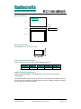
PCB Layout Recommendations
The recommended layout pads for the module are shown in the figure below. All dimensions
are in thousands of an inch (mil). The circle in upper left corner is an orientation mark only,
and should not be a part of the copper pattern.
A PCB with two or more layers and with a solid ground plane in one of the inner- or bottom
layer(s) is recommended. All GND-pins of the module shall be connected to this ground plane
with vias with shortest possible routing, one via per GND-pin.
On the back side of the module there are several test pads. These test pads shall not be
connected, and the area underneath the module should be covered with solder resist. If any
routing or vias is required under the module, the routing and vias must be covered with solder
resist to prevent short circuiting of the test pads. It is recommended that vias are tented.
Reserved pins should be soldered to the pads but the pads must be left floating.
2008 Radiocrafts AS
RC1180-MBUS Data Sheet (rev. 2.00)
Page 11 of 16
Radiocrafts
RC1180-MBUS
Embedded Wireless Solutions
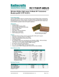
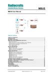
Mechanical Drawing
Radiocrafts
Embedded Wireless Solutions
Top view
RC10x0
CE
Shield can
Side view
End view
Bottom view
Drawings are not to scale
1.0" / 25.4 mm
0.5" / 12.7 mm
Mechanical Dimensions
The module size is 12.7 x 25.4 x 3.3 mm.
Carrier Tape and Reel Specification
Carrier tape and reel is in accordance with EIA Specification 481.
Tape width
44 mm
Component Hole pitch
pitch
16 mm
4 mm
Reel
diameter
13”
Units per
reel
Max 1000
Soldering Profile Recommendation
JEDEC standard IEC/JEDEC J-STD-020B (page 11 and 12), Pb-Free Assembly is
recommended.
The standard requires that the heat dissipated in the "surroundings" on the PCB is taken into
account. The peak temperature should be adjusted so that it is within the window specified in
the standard for the actual motherboard.
2008 Radiocrafts AS
RC1180-MBUS Data Sheet (rev. 2.00)
Page 12 of 16
Radiocrafts
RC1180-MBUS
Embedded Wireless Solutions
Absolute Maximum Ratings
Parameter
Min
Supply voltage, VCC
-0.3
Voltage on any pin
-0.3
Input RF level
Storage temperature
-50
Operating temperature
-40
Max
3.9
3.9
10
150
85
Unit
V
V
dBm
°C
°C
Caution ! ESD sensitive device.
Precaution should be used when handling
the device in order to prevent permanent
damage.
Under no circumstances the absolute maximum ratings given above should be violated.
Stress exceeding one or more of the limiting values may cause permanent damage to the
device.
Electrical Specifications
T=25°C, VCC = 3.0V if nothing else stated.
Parameter
Min
Operating frequency
868.0
Typ.
Max
Unit
870.0
MHz
Condition / Note
Number of channels
12
Input/output impedance
Ohm
50
Chip rate
S-mode
T-mode
R2-mode
32.768
100
4.8
kchip/s
Data rate
S-mode
T-mode
R2-mode
16.384
66.67
2.4
kbit/s
S and R2 mode use
Manchester coding. T mode
uses 3-of-6 coding. T2 use
a combination of both.
+/-40
+/-20
ppm
1
ppm/year
10
dBm
Including 10 years of aging.
TBD limited temperature
range for R2 mode
Starting after 10 years
Typical values are for
default settings
Frequency stability
S and T mode
R2 mode
Frequency stability aging
Transmit power
-20
9
FSK deviation
S-mode
T-mode
R2-mode
Adjacent channel power
+/- 50
+/- 50
+/- 6
TBD
kHz
dBc
Occupied bandwidth
TBD
kHz
99.5%
Spurious emission, TX
< 1 GHz
> 1 GHz
Sensitivity
S-mode
T-mode
R2-mode
Adjacent channel rejection
2008 Radiocrafts AS
-36
-30
-100
-100
-105
dBm
-102
-101
-106
dBm
29
dB
RC1180-MBUS Data Sheet (rev. 2.00)
Page 13 of 16
Radiocrafts
RC1180-MBUS
Embedded Wireless Solutions
Alternate channel selectivity
53
dB
Image channel rejection
28
dB
Blocking / Interferer rejection /
desensitization
+/- 1 MHz
+/- 2 MHz
+/- 5 MHz
+/- 10 MHz
dB
30
35
50
60
43
49
68
72
Saturation
-14
dBm
Input IP3
TBD
dBm
Wanted signal 3 dB above
sensitivity level, CW
interferer.
Minimum numbers
corresponds to class 2
receiver requirements in
EN300220.
Spurious emission, RX
Supply voltage
2.0
-57
dBm
3.6
V
Current consumption, RX/IDLE
Current consumption, TX
RF_POWER=5, 9 dBm
RF_POWER=4, 5 dBm
RF_POWER=3, 1 dBm
RF_POWER=2, -10 dBm
RF_POWER=1, -20 dBm
Current consumption, SLEEP
Digital I/O
Input logic level, low
Input logic level, high
Output logic level, low (1µA)
Output logic level, high(-1µA)
RESET pin
Input logic level, low
Input logic level, high
2008 Radiocrafts AS
mA
Apply over entire supply
voltage range
37
32
24
19
18
0.1
mA
Apply over entire supply
voltage range
70 %
0
TBD
1.0
uA
30 %
V
Of VCC
Of VCC
TBD
VCC
30 %
V
Minimum 250 ns pulse
width
70 %
UART Baud Rate tolerance
Configuration memory write
cycles
24
+/- 2
%
1000
RC1180-MBUS Data Sheet (rev. 2.00)
UART receiver and
transmitter
The guaranteed number of
write cycles using the ‘M’
command is limited
Page 14 of 16
Radiocrafts
Embedded Wireless Solutions
RC1180-MBUS
Document Revision History
Document Revision
1.0
1.1
Changes
First release
Pin Assignment and Pin Description: Pin 2 = RTS, Pin 3 = CTS. Changed
equivalent circuit to be pulled to VCC not VDD on relevant pins
Power supply chapter added. Frequency stability aging added.
Pin Assignment for Pin 2 and Pin 3 swapped, Pin 2 = CTS.
Added chapter “Programming interface”. Changed Test mode 2 description,
added Test mode 3 description.
UART_BAUD _RATE settings corrected.
Added R-C network on Reset-pin
Apply for firmware revision 1.15 and above (1.xx)
Added ‘F’ (set C-field) and ‘G’ (set M-Bus mode) commands
Added ‘T’ (set Destination Address / module ID) command
Minor corrections
MBUS protocol info separated into a User Manual
1.2
1.3
1.4
1.5
1.6
2.0
Product Status and Definitions
Current
Data Sheet Identification
Status
Product Status
Advance Information
Planned or under
development
Preliminary
Engineering
Samples and First
Production
No Identification Noted
Full Production
Obsolete
Not in Production
X
2008 Radiocrafts AS
RC1180-MBUS Data Sheet (rev. 2.00)
Definition
This data sheet contains the design
specifications for product
development. Specifications may
change in any manner without notice.
This data sheet contains
preliminary data, and
supplementary data will be
published at a later date.
Radiocrafts reserves the right to
make changes at any time without
notice in order to improve design
and supply the best possible
product.
This data sheet contains final
specifications. Radiocrafts reserves
the right to make changes at any time
without notice in order to improve
design and supply the best possible
product.
This data sheet contains
specifications on a product that has
been discontinued by Radiocrafts.
The data sheet is printed for
reference information only.
Page 15 of 16
Radiocrafts
Embedded Wireless Solutions
RC1180-MBUS
Disclaimer
Radiocrafts AS believes the information contained herein is correct and accurate at the time of this printing. However,
Radiocrafts AS reserves the right to make changes to this product without notice. Radiocrafts AS does not assume
any responsibility for the use of the described product; neither does it convey any license under its patent rights, or
the rights of others. The latest updates are available at the Radiocrafts website or by contacting Radiocrafts directly.
As far as possible, major changes of product specifications and functionality, will be stated in product specific Errata
Notes published at the Radiocrafts website. Customers are encouraged to check regularly for the most recent
updates on products and support tools.
Trademarks
RC232™ is a trademark of Radiocrafts AS. The RC232™ Embedded RF Protocol is used in a range of products from
Radiocrafts. The protocol handles host communication, data buffering, error check, addressing and broadcasting. It
supports point-to-point, point-to-multipoint and peer-to-peer network topologies.
All other trademarks, registered trademarks and product names are the sole property of their respective owners.
Life Support Policy
This Radiocrafts product is not designed for use in life support appliances, devices, or other systems where
malfunction can reasonably be expected to result in significant personal injury to the user, or as a critical component
in any life support device or system whose failure to perform can be reasonably expected to cause the failure of the
life support device or system, or to affect its safety or effectiveness. Radiocrafts AS customers using or selling these
products for use in such applications do so at their own risk and agree to fully indemnify Radiocrafts AS for any
damages resulting from any improper use or sale.
© 2008, Radiocrafts AS. All rights reserved.
Contact Information
Web site: www.radiocrafts.com
Address:
Radiocrafts AS
Sandakerveien 64
NO-0484 OSLO
NORWAY
Tel:
+47 4000 5195
Fax:
+47 22 71 29 15
E-mail: [email protected]
[email protected]
[email protected]
2008 Radiocrafts AS
RC1180-MBUS Data Sheet (rev. 2.00)
Page 16 of 16