1
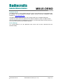
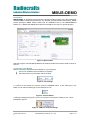
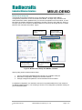
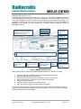
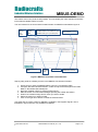
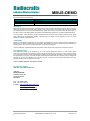
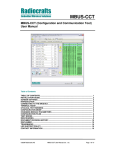
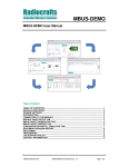
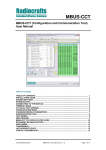
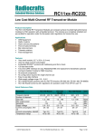
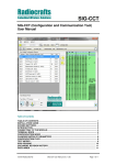
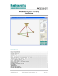
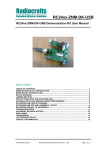
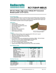
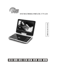
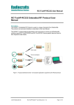
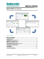
Radiocrafts
Embedded Wireless Solutions
MBUS-DEMO
MBUS-DEMO User Manual
Table of Contents
TABLE OF CONTENTS ............................................................................................................ 1
INSTALLATION GUIDE ............................................................................................................ 2
SCREEN SETTINGS ................................................................................................................. 2
INTRODUCTION ....................................................................................................................... 3
CONNECTING TO THE MODULE............................................................................................ 3
MODULE QUICK SETUP TAB ................................................................................................. 4
MBUS PACKET GENERATOR TAB ........................................................................................ 5
MBUS PACKET SNIFFER TAB ............................................................................................... 6
CONCENTRATOR INSTALL EMULATOR TAB ...................................................................... 7
ENCRYPTION KEY GENERATOR......................................................................................... 10
DOCUMENT REVISION HISTORY......................................................................................... 12
DISCLAIMER .......................................................................................................................... 12
TRADEMARKS ....................................................................................................................... 12
LIFE SUPPORT POLICY ........................................................................................................ 12
CONTACT INFORMATION ..................................................................................................... 12
2008 Radiocrafts AS
MBUS-DEMO User Manual (rev. 1.30)
Page 1 of 12
Radiocrafts
Embedded Wireless Solutions
MBUS-DEMO
Installation Guide
The MBUS-DEMO is a part of Radiocrafts’ RCTools PC suite tailored for use with Radiocrafts’
RF Modules. For full installation procedure please read the RCTools Installation Guide
available at www.radiocrafts.com.
The MBUS-DEMO requires access to the modules UART via an available COM-port.
Typically the UART-access is obtained via an UART-to-RS232 or UART-to-USB converter.
The Demo Boards (DB) from Radiocrafts contain an on-board level shifter for direct plug-in to
a PC and further access to the related COM-port.
Screen Settings
It is recommended to run the application with screen size at least 1024x768 and font
resolution 96dpi.
2008 Radiocrafts AS
MBUS-DEMO User Manual (rev. 1.30)
Page 2 of 12
Radiocrafts
Embedded Wireless Solutions
MBUS-DEMO
Introduction
MBUS-DEMO, is designed to demonstrate a Wireless M-Bus system using the Radiocrafts
Wireless MBUS module development kit. The program provides Module Quick setup, MBUS
Packet generator, MBUS Packet Sniffer and an Installation tool for the MBUS2/MBUS3
feature set. A Radiocrafts MBUS Demo Board is needed for this demo to operate properly.
Figure 1. Main window
Start the program, and the MBUS-DEMO main window should look similar to what is shown in
Figure 1.
Connecting to the Module
Before connecting, select the proper settings for your serial port:
name of an available communication port (COMx)
baud rate used to communicate with the module
Figure 2. Port settings
To connect to the module you need to press the connect button. If your COM port is not
listed you can also manually type in the COM port to use.
Figure 3. Connect button
A warning message will pop-up if you try to connect to a port that is already in use. This is
illustrated in figure 4.
Figure 4. COM port conflict message
2008 Radiocrafts AS
MBUS-DEMO User Manual (rev. 1.30)
Page 3 of 12
Radiocrafts
Embedded Wireless Solutions
MBUS-DEMO
Module Quick Setup Tab
The Module Quick setup Tab allows you to read back and configure basic MBUS
configuration parameters on the connected Demo Board. The input entry selections and
status information will be updated when you read the configuration from the module. A readback from the module should be the first thing to do after connect to the COM port. Some of
the input entries are not valid for all MBUS feature set, and they will be greyed out or hidden
based on the read back information. Figure
Update module setting
based on input entry
selection
Input entry selections
to store in module
Non-Volatile memory
MBUS mode and ID
status information
based on module read
Read module setting
and update input entry
and status.
Connected module
details
Figure 5. Module Quick Setup after MBUS3 read back
Step-by-step guide for Module Quick Setup:
1. Connect the Radiocrafts MBUS Demo Board to an available COM port
2. Read back configuration settings from the Demo Board
3. Change settings and update the connected Demo Board if needed.
For detailed configuration it is advised to use the more powerful MBUS-CCT tool instead of
the MBUS-DEMO software. You will then get access to all configuration parameter settings of
your connected module.
2008 Radiocrafts AS
MBUS-DEMO User Manual (rev. 1.30)
Page 4 of 12
Radiocrafts
Embedded Wireless Solutions
MBUS-DEMO
MBUS Packet Generator Tab
The MBUS Packet Generator Tab allows you to set up one of the RC1180-MBUS modules as
a meter that sends meter status on request or periodically. The UART package from the PC
to the RC1180-MBUS is listed, and part of the message can be changes by the user. This
package is received from the meter via the UART interface directly to the RC1180-MBUS as
illustrated in the picture. The user entries for the MBUS Packet Generator window is
illustrated in figure 6.
Start periodic send
Send a 0xFF wake-up byte before
the packet. Should be enabled when
MBUS2/MBUS3 is configured for
Auto sleep in quick-setup.
Set time resolution
for Packet rate
setting
Stop periodic send
Reset counter
Packet rate setting
for periodic TX
Total packet to
send for the
periodic TX
Select a packet
type to send to the
module
Number of packet
sent
UART Packet
format to the
module
Type the name of
the added packet
in the list
C-field stored in
Module volatile
Memory
Send the selected
packet to the module
once
Send the selected
packet to the module
Mailbox (MBUS3
only)
Select
Mailbox
Add the selected
packet to the packet
list selection
Figure 6. MBUS Packet Generator
Step-by-step guide for setting up the MBUS Packet Generator in periodic TX mode:
1.
2.
3.
4.
5.
6.
7.
Configure the Demo Board as Slave in the Module Quick Setup tab
Select the MBUS Packet Generator tab
Set the Packet rate that gives the periodical interval in ms (optional)
Set the total packets to transmit in the periodic test (optional)
Select a packet to transmit.
Change the packet payload if needed (optional)
Start the periodic transmit from the toolbar start button
The packet counter will now increment and send the UART packet periodically according to
the Packet rate until the total packets has been transmitted. The user can stop and reset the
periodic transmission from the toolbar.
2008 Radiocrafts AS
MBUS-DEMO User Manual (rev. 1.30)
Page 5 of 12
Radiocrafts
Embedded Wireless Solutions
MBUS-DEMO
MBUS Packet Sniffer Tab
The MBUS Packet Sniffer tab allows you to set up one of the RC1180-MBUS modules as a
Wireless M-Bus Collector. This board will act as a Wireless M-Bus packet sniffer, that
receives and lists all incoming Wireless M-Bus packets for the selected MBUS mode. The
user window for the MBUS Packet Sniffer is illustrated in figure 7.
Reset Packet Sniffer
Number of
packets Received
Stop Packet Sniffer
Start Packet Sniffer
Auto clear log to
recude the log list.
The packet counter
will not be cleared
MBUS
Packets
received log
Mouse-over tool-tip if
Data field larger than
window size
Send a packet from the MBUS
Packet generator Tab. To be
used to verify Auto-ACK feature
for MBUS2/MBUS3.
Select all packets in
the log. To be used for
Copy-paste into Excel
sheet.
Timestamp
when
received
Figure 7. MBUS Packet Sniffer
Step-by-step guide for setting up the MBUS Packet Sniffer:
1. Configure the Demo Board as Master, enable accept all messages and include RSSI
in the Module Quick Setup tab
2. Select the MBUS Packet Sniffer Tab
3. Start the MBUS Packet Sniffer from the toolbar start button
The MBUS Packet Sniffer will now count the total number of received MBUS packets and list
them in the Meter Collector data field including RSSI and packet ID for each new packet. The
meter collector will continue to search for MBUS packets until the Sniffer is stopped using the
stop button on the toolbar. All collector data can be selected in order to copy-paste the
information to an Excel spreadsheet for further analysis. The reset button will empty the
logger and set the packet receive counter to zero.
2008 Radiocrafts AS
MBUS-DEMO User Manual (rev. 1.30)
Page 6 of 12
Radiocrafts
Embedded Wireless Solutions
MBUS-DEMO
Concentrator Install Emulator Tab
The Concentrator Install Emulator tab is a tool for installing and binding meters to the
RC1180-MBUS module. The module will act as a Wireless M-Bus concentrator that only
accepts installed meters. This tab is not in use for MBUS1 and different for MBUS2 and
MBUS3. The user window for the Concentrator Install Emulator for MBUS2 is illustrated in
figure 8.
Start seach
for new
meters
Stop seach
for new
meter
Reset Install list. Will not clear the
installed meters in the module. To clear
installed meter go to quick setup tab.
Install selected meters
from the list
Avilable meters to install
Meter details
Select
to install
meter
Select to send a new packet
typ 100 ms after first ACK.
The selected packet form the
Packet Generator tab is
used.
Select to enable Auto ACK.
Will be auto cleared if
emulator started and a new
packet received from meter.
Enable
encryption
Read pre-installed
meters from module
Figure 8. MBUS2 Concentrator Install Emulator
Step-by-step guide for installing a meter to the MBUS2 Concentrator Emulator:
1. Ensure that you have the MBUS2 feature set on the connected module.
2. Configure the Demo Board as Master, enable accept Install messages and include
RSSI, in the Module Quick Setup tab.
3. Read pre-installed meters by pressing left-arrow key.
4. Start the search for new install messages pressing the toolbar start button.
5. Wait for the install message from a meter you want to install.
6. Select the meters you want to install
7. Click on the right-arrow button to install the selected meter.
If Auto ACK is enabled the Master will automatically send an ACK when receiving a new
message from the installed slave. The Auto ACK flag will be cleared after the Master send
this ACK. You may also enable to send a packet from the packet Generator tab after this first
ACK according to NTA8130.
You can change mode to normal mode and use the packet sniffer to receive messages from
installed meters only after the installation is completed. The Install Emulator will only list up
2008 Radiocrafts AS
MBUS-DEMO User Manual (rev. 1.30)
Page 7 of 12
Radiocrafts
Embedded Wireless Solutions
MBUS-DEMO
new meters even if they send several packets. This will simplify the meter selection and easily
inform about available meters to install.
The user window for the Concentrator Install Emulator for MBUS3 is illustrated in figure 9.
Start
seach for
new
meters
Stop seach
for new
meter
Reset Install list. Will not clear the
installed meters in the module. To clear
installed meter go to quick setup tab.
Avilable meters to
install
Select
to install
meter
Meter details
Install selected meters
from the list
Read pre-installed
meters from module
Figure 9. MBUS3 Concentrator Install Emulator
Step-by-step guide for installing a meter to the MBUS3 Concentrator Emulator:
1. Ensure that you have the MBUS2 feature set on the connected module.
2. Configure the Demo Board as Master, enable accept Install messages and include
RSSI, in the Module Quick Setup tab.
3. Read pre-installed meters by pressing left-arrow key.
4. Start the search for new install messages pressing the toolbar start button.
5. Wait for the install message from a meter you want to install.
6. Select the meters you want to install
7. Click on the right-arrow button to install the selected meter.
Auto ACK and encryption setting for MBUS3 is available in the Register flag tab. This is
illustrated in figure 10 and is only available for MBUS3.
2008 Radiocrafts AS
MBUS-DEMO User Manual (rev. 1.30)
Page 8 of 12
Radiocrafts
Embedded Wireless Solutions
MBUS-DEMO
Select the installed
slave to configure
Selection of Standard
message reply from
master
Update module flag
register for selected
slave
Encryption setting for
Master and Slave.
Select a Master reply
message from the
mailbox
Read module flag
register for selected
slave
Figure 10. MBUS3 Flag Register
The mailbox feature for MBUS3 can be read from the Mailbox tab. In figure 11 is illustrated a
readout when mailbox 1 and 3 is in use. To write to the mailbox use the packet generator tab
as shown in figure 6.
Figure 11. MBUS3 Mailbox readout
2008 Radiocrafts AS
MBUS-DEMO User Manual (rev. 1.30)
Page 9 of 12
Radiocrafts
Embedded Wireless Solutions
MBUS-DEMO
Encryption Key Generator
The Encryption Key Generator tab is a tool for MBUS2 and MBUS3 to calculate and update
the connected module with encryption keys. The view is different for MBUS2 and MBUS3 and
figure 12 shows MBUS3 Encryption key generator Tab.
Select this to get a
default test key for
master and slave
If Master select installed
slave register. If Slave use
installation register 1.
Update Master slave
with key
Calculates a random
Master and Slave key
on each button click.
Figure 12. MBUS3 Encryption Key Generator
Step-by-step guide for enable Encryption for MBUS3 Master:
1. Install a meter to a register 1-64.
2. Calculate an encryption key and update Master with key to installed slave register.
3. Enable encryption in the Concentrator Install Emulator / Flag Register (see figure 9 )
Step-by-step guide for enable Encryption for MBUS3 Slave:
1. Update Slave with same encryption key as the Master to slave register 1.
2. Enable encryption in the Concentrator Install Emulator / Flag Register 1 (see figure
10 )
2008 Radiocrafts AS
MBUS-DEMO User Manual (rev. 1.30)
Page 10 of 12
Radiocrafts
Embedded Wireless Solutions
MBUS-DEMO
Figure 13 shows MBUS2 Encryption key generator Tab.
Select to get a default
test key for master
and slave
Calculates a random
Master and Slave key
on each button click.
If Master select installed
slave register.
Update Master slave with key
Update Slave with key
Slave encryption enable. If
Master enable encryption in
the Consentrator Emulator
Option to add Slave key to packet list in the
packet generator tab. Usefull if you want to
include the slave key in a message from a
Master.
Figure 13. MBUS2 Encryption Key Generator
Step-by-step guide for enable Encryption for MBUS3 Master:
4. Install a meter to a register 1-8.
5. Calculate an encryption key and update Master with key to installed slave register.
6. Enable encryption in the Concentrator Install Emulator (see figure 8 )
Step-by-step guide for enable Encryption for MBUS3 Slave:
3. Update Slave with the encrypted Master Key.
4. Enable encryption in the Encryption Key Generator tab
2008 Radiocrafts AS
MBUS-DEMO User Manual (rev. 1.30)
Page 11 of 12
Radiocrafts
Embedded Wireless Solutions
Document Revision History
Document Revision
1.0
1.1
1.30
MBUS-DEMO
Changes
New Revision
Upgraded with MBUS2 feature set functions (MBUS-DEMO rev 1.10)
Upgrades with MBUS3 features (MBUS-DEMO 1.33)
Disclaimer
Radiocrafts AS believes the information contained herein is correct and accurate at the time of this printing. However,
Radiocrafts AS reserves the right to make changes to this product without notice. Radiocrafts AS does not assume
any responsibility for the use of the described product; neither does it convey any license under its patent rights, or
the rights of others. The latest updates are available at the Radiocrafts website or by contacting Radiocrafts directly.
As far as possible, major changes of product specifications and functionality, will be stated in product specific Errata
Notes published at the Radiocrafts website. Customers are encouraged to check regularly for the most recent
updates on products and support tools.
Trademarks
RC232™ is a trademark of Radiocrafts AS. The RC232™ Embedded RF Protocol is used in a range of products from
Radiocrafts. The protocol handles host communication, data buffering, error check, addressing and broadcasting. It
supports point-to-point, point-to-multipoint and peer-to-peer network topologies.
All other trademarks, registered trademarks and product names are the sole property of their respective owners.
Life Support Policy
This Radiocrafts product is not designed for use in life support appliances, devices, or other systems where
malfunction can reasonably be expected to result in significant personal injury to the user, or as a critical component
in any life support device or system whose failure to perform can be reasonably expected to cause the failure of the
life support device or system, or to affect its safety or effectiveness. Radiocrafts AS customers using or selling these
products for use in such applications do so at their own risk and agree to fully indemnify Radiocrafts AS for any
damages resulting from any improper use or sale.
© 2010, Radiocrafts AS. All rights reserved.
Contact Information
Web site: www.radiocrafts.com
Address:
Radiocrafts AS
Sandakerveien 64
NO-0484 OSLO
NORWAY
Tel: +47 4000 5195
Fax: +47 22 71 29 15
E-mails: [email protected]
[email protected]
[email protected]
2008 Radiocrafts AS
MBUS-DEMO User Manual (rev. 1.30)
Page 12 of 12