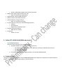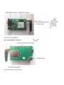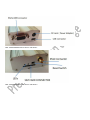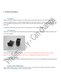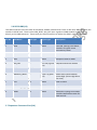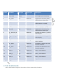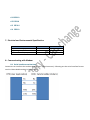
1
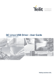
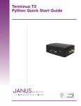
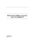
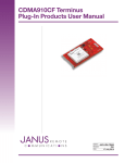
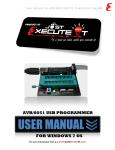
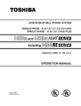
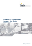
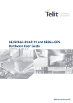
Calixto-Telit xE910 MODEM
User Manual
© 2014 Calixto Systems Pvt Ltd.
All Rights Reserved. No part of this document may be photocopied, reproduced, stored in a retrieval
system, or transmitted, in any form or by any means whether, electronic, Mechanical, or otherwise
without the prior written permission of Calixto Systems. No warranty of accuracy is given concerning the
contents of the information contained in this publication. To the extent permitted by law no liability
(including liability to any person by reason of negligence) will be accepted by Calixto Systems or
employees for any direct or indirect loss or damage caused by omissions from or inaccuracies in this
document.
Calixto Systems reserves the right to change details in this document without notice. Product and
company names herein may be the trademarks of their respective owners.
#111, First Floor, 2H Main Road, Kasturi Nagar, Bangalore, India -560 043.
Web: www.calixtosystems.com Email: [email protected]
___________________________________________________________________________________
Revision History
Date
08/02/2014
Revision
0.1
Remarks
First version created
Table of Contents
1.
Introduction ................................................................................................... 5
2.
CST-xE910-MODEM General Features: .......................................................... 5
3.
Calixto CST-xE910-XX-MODEM ordering Info ................................................. 6
3.1
Product Variants ....................................................................................................................... 6
4.
Product details ............................................................................................... 6
5.
Hardware Description .................................................................................... 9
5.1
Antenna.................................................................................................................................... 9
5.2
Power Jack................................................................................................................................ 9
5.3
LED Indications ......................................................................................................................... 9
5.4
Battery connector ..................................................................................................................... 9
5.5
USB – Mini USB connector: ....................................................................................................... 9
5.6
RS232-DB9 (J3) ....................................................................................................................... 10
5.7
Expansion Connector Slot (J14) ............................................................................................... 10
6.
Telit Module Details: ................................................................................... 11
6.1
HE910 ..................................................................................................................................... 12
6.2
UE910..................................................................................................................................... 12
6.3
GE910 ..................................................................................................................................... 12
6.4
CE910 ..................................................................................................................................... 12
7.
Electrical and Environmental Specification .................................................. 12
8.
Communicating with Modem....................................................................... 12
8.1
Serial Interface mechanism..................................................................................................... 12
8.2
9.
Communication Software ....................................................................................................... 13
Legal Notice ................................................................................................. 15
9.1
Customer Support: ................................................................................................................. 15
9.2
Usage Restriction: ................................................................................................................... 15
10.
Warranty and Return Policy ..................................................................... 15
10.1
Warranty Period: .................................................................................................................... 15
10.2
Warranty Coverage:................................................................................................................ 15
10.3
Product Repair:....................................................................................................................... 16
10.4
RMA (Return Merchandise Authorization) .............................................................................. 16
1. Introduction
This document talks about details of Calixto’s Telit xE910 family based modems.
Telit offers its customers a form factor and family concept. Part of this concept is the xE910 family of
wireless modules featuring a single, compact form factor that is interchangeable on any regional cellular
network, delivering ubiquitous, cost-effective coverage for M2M applications and consumer electronics
devices worldwide.
Based on a Land-Grid-Array (LGA) form factor with a footprint of just 795mm2 and a total size of 28.2 x
28.2 x 2.2mm, the Telit xE910 family's uniform design gives customers the ability to choose between global
or regional cellular technologies depending upon the location and requirements of a specific application
for optimum data rates and module costs.
Supporting GSM/GPRS, UMTS/HSPA+ and CDMA/EV-DO cellular technologies, the xE910 family also allows
applications to be easily upgraded, such as when migrating from 2G to 3.5G, while maintaining the core
design of an application or device throughout its lifecycle. This allows M2M developers and device
manufacturers to easily customize their applications by enabling simple module integration and upgrades.
Calixto xE910 modems are optimum, ready to use solution for customers of Machine to Machine (M2M)
applications. This module is based on Telit xE910 family of modules. Calixto provides optional battery
charging feature and GPS support for selected modules.
These modems can also be used as ideal evaluation platform to evaluate xE910 modules from Telit.
Some key application areas include:
• Industrial M2M communications
• Remote Monitoring and Control
• Point of Sale Terminals
• Metering
• Warehousing
• Logistics and Freight Management
.Note: There is optional rugged, yet lightweight aluminum enclosure available for this modem.
2. CST-xE910-MODEM General Features:
•
•
Based on Telit xE910 family of Modules
Currently supported modules are
o HE910: 3G UMTS, HSPA+ with GPRS/EDGE and optional GPS
o UE910: 3G UMTS, HSPA modules
o CE910_SC: Single Band CDMA 1xRTT module.
•
•
•
•
•
•
•
o GE910: GSM/GPRS modem with USB 2.0 interface.
Wide power input range from 9 to 24 Volt
o Ideal for automotive applications.
USB Interface with miniUSB connector.
RS232 interface with DB9 connector
Optional battery charger feature
o Ideal for remote monitoring
14 pin Expansion connector with following interfaces
o 3 GPIOS
o SPI Interfaces
o Digital Voice Interfaces (DVI)
Antenna connector options
o SMA and uFL options
Dimension
o 50mm x 75 mm
3. Calixto CST-xE910-XX-MODEM ordering Info
3.1 Product Variants
There are many variants of the module available:
• Standard modem with xE910 modules varieties are:
o CST-HE910-XXX-MODEM (XXX is for different variation of HE910-EUD, EUG etc).
o CST-CE910-SC-MODEM
o CST-GE910-XX-MODEM
• CST-xE910 with battery charging interface: CST-xE910-XX-MODEM-BC
4. Product details
The figures below shows pictures of CST-GL868-MODEM-BC with important components marked. SIM card
holder is in the other side of the board as in second picture.
FIG1: xE910 MODEM: TOP VIEW
FIG2: xE910 MODEM: BOTTOM VIEW
FIG3: xE910 MODEM with Enclosure: Side View 1
FIG4: xE910 MODEM with Enclosure: Side View 2
5. Hardware Description
5.1 Antenna
Antenna connector allows transmission of radio frequency (RF) signals between the modem and an external
customer-supplied antenna. Calixto provides option one of the two antenna connectors. One is uFL and other
one is 50ΩFME male coaxial jack. As an option Calixto provides WIP Antenna with 50ΩFME male coaxial jack
connector.
For modules with GPS functionality, there is a provision for uFL and SMA connector.
5.2 Power Jack
The power Jack supported is 2mm DC power jack with locking option. The figure below shows the power jack
used in the modem.
5.3 LED Indications
There are two LEDs in the xE910 modem. The LED1 (at D3) is POWER indicator LED The LED1 (at D8) is
MODULE status LED. For CST-xE910-xx- BC, there is an additional Charging Indicator LED (D4).
5.4 Battery connector
CST-xE910-MODEM-BC modem has additional battery connector. This is a 2 pin RELIMATE connector (location
B1).
5.5 USB – Mini USB connector:
Calixto xE910 modems come with USB device connector (at J4). USB is directly connected to USB signals of modules.
Please note that GE910-QUAD-V3 does not have USB interface.
5.6 RS232-DB9 (J3)
This DB9 connector has main UART of the xA910 module in RS232 level. There is also DCD, RING pins from the
module in RS232 level. There is also GSM_RESET, ON_OFF input signals to GL86x module at 0-3.6 V level
directly to this DB9 connector. These extra pins allow customers to utilize the xE910 module completely.
Pin No
PIN Name
Pin Type
Signal Type
Description
1
DCD
O
RS232
DCD PIN. Coming from xE910
module. This gives server
connectivity status.
2
TXD
O
RS232
Transmit Data of RS232
3
RxD
I
RS232
Reception Data for UART
4
ON_OFF
I
0 to 3.6 (Typical
3.3)
ON/OFF PIN OF the module
5
GND
Gnd
6
MODULE_RESET
I
0-3.6 V (Typical
3.3)
Reset PIN of xE910 module.
Active High. (20 ms High Pulse
for reset)
7
CTS
O
RS232
Clear to Send
8
RTS
I
RS232
Request to Send
9
RING
O
RS232
RING PIN. Coming from xE910
module. Notification status for
SMS and call.
5.7 Expansion Connector Slot (J14)
Ground
Pin No
PIN Name
Pin Type
Signal Type
Description
1
VCC_3V8D
Power
2
DVI_WA0
I/O
CMOS1.8V
Digital Voice Interface (WA0).
16K Pull down when Input.
3
DVI_Rx
I
CMOS1.8V
Digital Voice Interface (RX).
16KPull down is needed.
4
DVI_Tx
I/O
CMOS1.8V
Digital Voice Interface (TX).
5
DVI_CLK
I/O
CMOS1.8V
Digital Voice Interface (CLK).
16K Pull down when Input.
6
SPI_MOSI/Tx_AU
X
I
CMOS1.8V
SPI MOSI for HE910, Tx_AUX for
GE910 QUAD
7
SPI_MISO/Rx_AU
X
O
CMOS1.8V
SPI MISO for HE910, Rx_AUX for
GE910 QUAD
8
SPI_CLK
I
CMOS1.8V
SPI CLK for HE910. Not used for
other modules.
9
SPI_MRDY
I
CMOS1.8V
SPI MRDY for HE910. Not used
for other modules.
10
SPI_SRDY
O
CMOS 1.8V
SPI SRDY for HE910. Not used
for other modules.
11
GPIO_2
I/O
CMOS 1.8V
GPIO_2 from Module
12
GPIO_3
I/O
CMOS 1.8V
GPIO_3 from Module
13
GPIO_4
I/O
CMOS 1.8V
GPIO_4 from Module
14
GND
Gnd
3.8V supply (to use outside)
Digital Ground
6. Telit Module Details:
Calixto xE910 module designed for all members of Telit’s xE910 family of modules.
6.1 HE910
6.2 UE910
6.3 GE910
6.4 CE910
7. Electrical and Environmental Specification
Parameter
Min
Max
Input Power Supply -DC
Operating Temperature
Relative humidity - Operational
9-24V
-250 C
10%
9-24V
+850 C
90%
8. Communicating with Modem
8.1 Serial Interface mechanism
Customers can interface the modem through main (DB9 Connector). Following are the serial interface format
used in Calixto GL86x modem in below figure:
The CST-GL868-MODEM is built around Telit GL86x module. Customers can follow all the programing
mechanism suggested by Telit.
8.2
Communication Software
Customer can use any serial terminal program in PC to communicate with modem. We have used “rsterm” for
our development and test. Below figure shows typical screen shot of “rsterm”.
Customer can use either AT commands or program the GL86x module with Python script defined by Telit.
Some of the documents to be referred are:
1. Telit Modules Software User Guide_r13 (1vv0300784 Rev.13 2013-02-14)
2. Telit AT Command Reference guide_r16 (80000ST10025a Rev.16 -2013-02-07)
3. Telit Easy Script Python_r15 (80000ST10020a Rev 15 -2012-10-09)
4. Telit CMUX Implementation User Guide_r3 (1VV0300994 Rv0.3 – 2013-02-15)
5. Telit SIM Access Profile User Guide_r3 (80000ST10029a Rev.3-2011-03-01)
6. Telit IP Easy User Guide_r15 (80000ST10028A rev 15-2013-02-19)
9. Legal Notice
9.1 Customer Support:
Calixto Systems are excited to offer our customers an easy “out of box” experience by providing board support
package, software demos, user manuals and other electro mechanical documentation to get our evaluation
modules up and running. We also provide further electronic (email, wiki and discussion forum) support for
evaluation of our modules using corresponding Calixto boards.
Customer product development support is not part of standard support offer from Calixto systems. If
customers are interested, Calixto can offer product development services around Calixto modules.
9.2 Usage Restriction:
Calixto products are excellent starting point for customer’s applications development. But, selection and usage
of Calixto systems products for a particular application is responsibility of customers. In order to minimize risks
associated with customer applications, the customer must use adequate design and operating safeguards to
minimize inherent or procedural hazards.
Calixto systems products are not intended for use in life support systems and appliances, nuclear systems or
systems where malfunction can reasonably be expected to result in personal injury, death or severe property
or environmental damage. Any use of products by the customer for such purposes are at the customer’s own
risk.
Off the shelf products from Calixto systems are commercial temperature grade. If customers are looking for
Industrial or Extended temperature products, please order them specifically.
10. Warranty and Return Policy
10.1 Warranty Period:
Calixto Systems guarantees hardware products against defects in workmanship and material for a period of twelve (12)
months from the date of shipment.
10.2 Warranty Coverage:
Calixto systems at its sole discretion, to either repair or replace the defective hardware product at no charge.
Shipment costs in both directions are the responsibility of the customer. The warranty is void if the hardware
product has been altered or damaged by accident, misuse or abuse. The warranty is void if the damage is due
to the shipping of the Products and other external causes like problems with electrical power, usage not in
accordance with product instruction, and problems caused by use of parts and components not supplied by
Calixto systems.
This warranty does not cover any items that are in one or more of the following categories:
a.
b.
c.
d.
Software and/or device drivers,
External devices,
Accessories or parts added to products after the products shipped from Calixto Systems.
All Warranty terms are subject to change without prior notice.
10.3 Product Repair:
•
•
•
•
•
Calixto systems shall repair the defective products covered under this warranty that are returned to
Calixto systems.
Calixto systems shall own all parts removed from repaired products.
Calixto systems will use parts made by various manufacturers in performing the repair. This can be
different from the components used in the original products.
The repaired products shall be warranted subjected to the original warranty only (If the original warranty
period left was three months, the repaired product warranty will be only for three months)
Customers shall agree that an independent third party assigned by Calixto Systems may repair the
products covered under this limited warranty.
10.4 RMA (Return Merchandise Authorization)
•
•
•
Customer shall enclose the completed "Calixto Systems RMA Service Form" with the returned packages.
Customers shall provide all the relevant information of the defect in the “Calixto Systems RMA Service
Form”. This will reduce delay in defect identification and repair.
Customers shall take responsibility to ensure that the packages of defective Products are durable enough
to be resistant against further damage and deterioration during shipment. In case of damages occurred
during the transportation, the repair is treated as “Out of Warranty”.