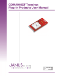
1
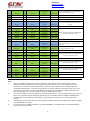
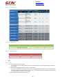
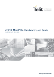
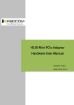
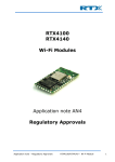
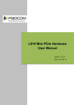
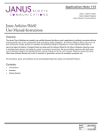
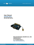
GLYN Ltd www.glyn.com.au www.glynstore.com GFF910 Hardware Reference Manual Revision 1.2 28 April 2014 Revision History Revision 1.0 1.1 1.2 Revision History Initial release Update to current production settings Change colour coding for function shared pin 63 1 Date 21/11/2012 08/04/2014 28/04/2014 GLYN Ltd www.glyn.com.au www.glynstore.com Table of Contents 1 Introduction ..................................................................................................................................... 3 1.1 Overview................................................................................................................................................. 3 2 Mechanical Specification ................................................................................................................. 3 2.1 Dimension............................................................................................................................................... 3 2.2 Socket Types ........................................................................................................................................... 4 2.2.1 80 way plug specifications ........................................................................................................... 4 2.2.2 80 way socket specifications ....................................................................................................... 4 2.2.3 Top UFL connectors ..................................................................................................................... 5 3 Module Connections ....................................................................................................................... 5 3.1 Pin out .................................................................................................................................................... 5 3.2 Antenna Connectors ............................................................................................................................... 8 4 Hardware Commands ...................................................................................................................... 9 5 Power Supply ................................................................................................................................... 9 5.1 Power Supply Requirements .................................................................................................................. 9 5.2 Power Consumption ............................................................................................................................... 9 6 GSM/WCDMA Radio Section ........................................................................................................... 9 6.1 GFF910 Production Variants................................................................................................................... 9 6.1.1 4G Variants .................................................................................................................................. 9 6.1.2 3G Variants ................................................................................................................................ 10 6.1.3 2G Variants ................................................................................................................................ 10 6.1.4 CDMA Variants .......................................................................................................................... 10 7 Q&A ............................................................................................................................................... 10 7.1 GPIO ...................................................................................................................................................... 10 7.2 SPI ......................................................................................................................................................... 11 7.3 DVI ........................................................................................................................................................ 11 7.4 UART ..................................................................................................................................................... 11 7.5 UART_TRACE ........................................................................................................................................ 11 7.6 VAUX1 ................................................................................................................................................... 11 7.7 VRTC ..................................................................................................................................................... 11 7.8 RESET .................................................................................................................................................... 11 7.9 ON/OFF ................................................................................................................................................. 12 7.10 SIM INTERFACE .................................................................................................................................. 12 7.11 ADC .................................................................................................................................................... 12 7.12 STAT_LED ........................................................................................................................................... 12 7.13 POWER SUPPLY.................................................................................................................................. 12 2 GLYN Ltd www.glyn.com.au www.glynstore.com 1 Introduction 1.1 Overview The GFF910 module is designed to allow the user easy plug and play options for GSM, UMTS, HSPA and CDMA. With plug and play options via the Telit Global Form Factor the entire range of xE910 modules are supported and options such as voice and GPS can easily be fulfilled without the need for re-work or re-design. By providing an 80 way Global Form Factor interface the GFF910 allows the user the option to mount the module which best fits their application. In most cases your design needs to provide flexibility depending which region the product is to be deployed and or certified. The GFF910 form factor takes the guess work out of the design by providing a single connector for interfacing the entire range of radio types depending on your needs. Full electrical and software (AT command) compatibility is maintained between each module type be it GSM (GFF910-GE), CDMA (GFF910-DE or GFF910-CE) or HSPA+ (GFF910-G). 2 Mechanical Specification 2.1 Dimension Length: 36.2mm Width: 30mm 3 GLYN Ltd www.glyn.com.au www.glynstore.com Thickness: 5.6mm 3 6 . 2 m m 2.2 Socket Types 2.2.1 80 way plug specifications Manufacture: Molex Inc. Part Number: 0539490878 2.2.2 80 way socket specifications Manufacture: Molex Inc. Part Number: 0541500878 4 GLYN Ltd www.glyn.com.au www.glynstore.com 2.2.3 3 Top UFL connectors Manufacture: Taoglas Limited Part Number: RECE-20279-001E-01 Module Connections 3.1 Pin out GFF910 Family uses an 80 pin Molex p.n. 53949-0878 male connector for the connections with the external applications. This connector matches the 54150-0878 models. PIN SIGNAL I/O FUNCTION WORKING RANGE TYPE COMMENT Power Supply 1 VBAT * Main power supply POWER 3.4V~4.20V 2 VBAT * Main power supply POWER 3.4V~4.20V 3 VBAT * Main power supply POWER 3.4V~4.20V 4 VBAT * Main power supply POWER 3.4V~4.20V 5 GND * Ground POWER * 6 GND * Ground POWER * 7 GND * Ground POWER * 8 * * * * * 9 NC * * * EAR+ 10 NC * * * EAR- 11 * * * * * 12 * * * * * 13 NC * * * MIC+ 14 NC * * * MIC- 15 * * * * * 16 * * * * * 17 * * * * * 18 SIMVCC * 19 SIMRST O 20 SIMIO I/O 21 SIMIN I 22 SIMCLK O Power for the SIM External SIM signalRESET External SIM signalData I/O External SIM signalPresence(active low) External SIM signal Clock SIM Card Interface SIM CARD INTERFACE 1.8V/3V SIM CARD INTERFACE 1.8V/3V SIM CARD INTERFACE 1.8V/3V SIM CARD INTERFACE CMOS 1.8V SIM CARD INTERFACE 1.8V/3V refer to HE910_Hardware_User_Guide refer to HE910_Hardware_User_Guide Analog Audio, only EAR+, EAR-, MIC+ and MICavailable on modules have analog voice interface, e.g. GE910 and CE910. * refer to HE910_Hardware_User_Guide Trace 23 RX_TRACE/SPI_MOSI I/O 24 TX_TRACE/SPI_MISO I/O 25 C103/TXD I 26 C104/RXD O RX Data for debug monitor TX Data for debug monitor Serial data input (TXD) from DTE Serial data output to DTE Trace CMOS 2.8V Trace CMOS 2.8V Prog. /Data + Hw Flow Control Prog. / Data + Hw Flow Control CMOS 2.8V Prog. / Data + Hw Flow Control CMOS 2.8V 5 Working voltage depends on U2 (MIC5365/62.8). Can be adjusted to 2~5V. Shared with SPI TX & RX Working voltage depends on U2 (MIC5365/62.8). Can be adjusted to 2~5V. GLYN Ltd www.glyn.com.au www.glynstore.com 27 C107/DSR O 28 C106/CTS O 29 C108/DTR I 30 C125/RING O 31 C105/RTS I 32 C109/DCD O Output for Data set ready signal (DSR) to DTE Output for Clear to send signal (CTS) to DTE Input for Data terminal ready signal (DTR) from DTE Output for Ring indicator signal (RI) to DTE Input for Request to send signal (RTS) from DTE Output for Data carrier detect signal (DCD) to DTE 33 * * 34 * 35 Prog. / Data + Hw Flow Control Prog. / Data + Hw Flow Control CMOS 2.8V CMOS 2.8V Prog. / Data + Hw Flow Control CMOS 2.8V Prog. / Data + Hw Flow Control CMOS 2.8V Prog. / Data + Hw Flow Control CMOS 2.8V Prog. / Data + Hw Flow Control CMOS 2.8V * * * * * * * * * * * * * * * 36 DVI_CLK I/O Digital Audio Interface (CLK) Digital Audio Interface CMOS 2.8V 37 ACD_IN1 AI analog ADC input Analog Interface 0 - 2.8V Only available on HE910 and CE910 38 * * * * * * 39 * * * * * * 40 * * * * * * 41 SPI_MRDY I/O MRDY SPI interface CMOS 2.8V 42 SPI_SRDY I/O SRDY SPI interface CMOS 2.8V 43 SPI_CLK I/O CLK SPI interface CMOS 2.8V Not available on GE910 44 SPI_CS_N(NC) I/O SPI SLAVE SELECT SPI interface CMOS 2.8V Only available on DE910 and CE910 Working voltage depends on U2 (MIC5365/62.8). Can be adjusted to 2~5V. Only available on HE910 Miscellaneous Functions CMOS 2.8V Working voltage depends on U2 (MIC5365/62.8). Can be adjusted to 2~5V. Shared with GPIO1 45 STAT_LED O Status indicator led Miscellaneous Functions 46 GND * Ground * * * 47 * * * * * 48 USB_VBUS I * Power sense for the internal USB transceiver. Miscellaneous Functions 5V 49 PWRMON O 50 VAUX O Supply Output for external accessories / Power ON Monitor Miscellaneous Functions Miscellaneous Functions 51 * * * * * 52 * * * 5V CMOS 2.8V Working voltage depends on U2 (MIC5365/62.8). Can be adjusted to 2~5V.Max 50mA on VAUX CMOS 2.8V 53 ON/OFF I * Input command for power ON 54 RESET I Reset input * Miscellaneous Functions Miscellaneous Functions Power CMOS 1.8V CMOS 1.8V * * Active low Active low backup for the embedded RTC supply, refer to HE910_Hardware_User_Guide 55 VRTC I VRTC Backup capacitor Miscellaneous Functions 56 * * * * * * 57 * * * * * * 58 * * * * * * 6 GLYN Ltd www.glyn.com.au www.glynstore.com Working voltage depends on U2 (MIC5365/62.8). Can be adjusted to 2~5V. 59 GPIO_04 I/O GPIO_04 Miscellaneous Functions 60 * * * * * * 61 * * * * * * 62 * * * * * 63 GPIO_10 I/O GPIO_10 Miscellaneous Functions CMOS 2.8V * Working voltage depends on U2 (MIC5365/62.8). Can be adjusted to 2~5V. Optional for DVI_TX 64 * * * DVI_RX I/O 66 GPIO_03 I/O GPIO_03 67 GPIO_08 I/O GPIO_08 68 GPIO_06 I/O GPIO_06 * Miscellaneous Functions Miscellaneous Functions Miscellaneous Functions Miscellaneous Functions * 65 * Digital Audio Interface (RX) 69 * * * * * 70 GPIO_01 I/O GPIO_01 Miscellaneous Functions CMOS 2.8V Miscellaneous Functions * * CMOS 2.8V Working voltage depends on U2 (MIC5365/62.8). Can be adjusted to 2~5V. * CMOS 2.8V CMOS 2.8V CMOS 2.8V CMOS 2.8V CMOS 2.8V 71 DVI_WA0 I/O Digital Audio Interface (WA0) 72 * * * 73 GPIO_07 I/O GPIO_07 74 GPIO_02 I/O GPIO_02 * Miscellaneous Functions Miscellaneous Functions 75 * * * * CMOS 2.8V * 76 GPIO 9 I/O GPIO 9 Miscellaneous Functions 77 * * * * 78 GPIO_05 I/O GPIO_05 79 USB_D+ I/O USB differential Data + 80 USB_D- I/O USB differential Data - NOTE: 1: 2: 3: 4: Miscellaneous Functions Miscellaneous Functions Miscellaneous Functions Working voltage depends on U2 (MIC5365/62.8). Can be adjusted to 2~5V. CMOS 2.8V * Working voltage depends on U2 (MIC5365/62.8). Can be adjusted to 2~5V. Shared with STAT_LED Working voltage depends on U2 (MIC5365/62.8). Can be adjusted to 2~5V. CMOS 2.8V CMOS 2.8V * * * Working voltage depends on U2 (MIC5365/62.8). Can be adjusted to 2~5V. * Working voltage depends on U2 (MIC5365/62.8). Can be adjusted to 2~5V. * * GPIO_01 on HE910 modem goes to both pin 45 and pin 70 via different level translators(to Pin 45 via a direction fixed level translators that it can supply large output current, to pin 70 via a bidirectional level translators, for customers need the GPIO functions.), because of the GPIO_01 on the HE910 modem has configurable multifunction. So if the STAT_LED function is used for indicate the network status, then it can't be used for normal GPIO, in order to make GFF910 compatible with old GC864 and UC864 modems for the STAT_LED and GPIO_01. That's why it goes to 2 pins on the 80 way connector. For a common design if only STAT_LED function is used and the GPIO_1 is not used applications, Please use pin 45 for STAT_LED and leave pin 70 floating. Because this pin compatible with other UC864 and GC864 family modems. But for some applications that GPIO_1 is very essential, please use pin 70 and leave pin 45 no connect. ON/OFF pulse (pull down) needs to be a bit longer than UC864-G especially when USB cable is attached. (Refer to the HE910 HW User Guide) AT command set is not 100% compatible e.g. default AUTOBND is 2 in HE910. (Refer to the HE910 Software and AT command User Guide) 7 GLYN Ltd www.glyn.com.au www.glynstore.com 5: 6: 7: 8: 9: 10: 11: GFF910 provides maximum 10 GPIO, and GPIO 1 is shared with STAT_LED. (Refer to the GFF910 H/W User guide) GFF910 provides 1x ADC while UC864-G provides 2. IP address can no longer have any leading zeroes for example 169.192.012.2 should be 169.192.12.2. IP addresses with leading zeroes are converted to an octet and this is in line with the normal Windows IP addressing. Python interpreter has been enhanced from the old version 1.5.2+ supported in Elite and Xgold platforms to version 2.7.2. (Refer to the Telit Easy Script Python 2.7.2 document) Pin 63 is a shared with GPIO_10 and DVI_TX, it connected to GPIO_10 by default. If DVI_TX needed, will need some hardware modifications. DVI port is configured as Master only, please let us know if you need DVI port configured as Slave port. Colour Coding 100% compatible with UC864-G, if only these pins are used in your applications, GFF910 can replace old UC864/GC864 Function shared pins. Pin 45 and 70 are coming out from GPIO_01 on xE910 via different level translators. Pin63 can be configured as DVI_TX, please let us know if you need digital voice pin DVI_TX. Directly from xE910, please refer xE910 hardware user manual for details Special Function pins only available on some xE910 modules Analog audio pins, depending on the availability on xE910 modules, please refer to the right xE910 user manual for more details. 12: 13: RTS must be connected to the GND (on the module side) if flow control is not used If not used, almost all pins must be left disconnected. The only exceptions are the Following: Pin Signal Function 1 VBATT Main power supply 2 VBATT Main power supply 3 VBATT Main power supply 4 VBATT Main power supply 5 GND Ground 6 GND Ground 7 GND Ground 46 GND Ground 25 C103/TXD Serial data input (TXD) from DTE 26 C104/RXD Serial data output to DTE 31 C105/RTS Input for Request to send signal (RTS) from DTE 53 ON/OFF Input command for switching power ON or OFF (toggle command). 54 RESET Reset input 3.2 Antenna Connectors The GFF910 module is equipped with a 50 Ohm RF connector from Taoglas Limited, GSC type P/N: RECE-20279001E-01 for Antenna, Diversity and GPS antenna connection. These connectors are located on top side of the module. Interface cables are available: http://www.glynstore.com/pages/RF-Cable-Selection-Guide.html 8 GLYN Ltd www.glyn.com.au www.glynstore.com 4 Hardware Commands Please see Telit_HE910_Hardware_User_Guide for more details. Here is the download link: http://www.telit.com/en/products/umts.php?p_id=14&p_ac=show&p=108 5 Power Supply Please see Telit_HE910_Hardware_User_Guide for more details. Here is the download link: http://www.telit.com/en/products/umts.php?p_id=14&p_ac=show&p=108 5.1 Power Supply Requirements Please see Telit_HE910_Hardware_User_Guide for more details. Here is the download link: http://www.telit.com/en/products/umts.php?p_id=14&p_ac=show&p=108 5.2 Power Consumption Please see Telit_HE910_Hardware_User_Guide for more details. Here is the download link: http://www.telit.com/en/products/umts.php?p_id=14&p_ac=show&p=108 6 GSM/WCDMA Radio Section 6.1 GFF910 Production Variants 6.1.1 4G Variants GFF910-LE 9 GLYN Ltd www.glyn.com.au www.glynstore.com 6.1.2 3G Variants Product GFF910-G GFF910-DG GFF910-D GFF910-EUR GFF910-EUD GFF910-EUG GFF910-NAR GFF910-NAD GFF910-NAG 6.1.3 2G Variants Variants GFF910-GE GFF910-GN 6.1.4 Voice YES YES GPS NO YES Notes GE910-QUAD GE910-GNSS CDMA Variants Variants GFF910-CE GFF910-DE 7 Frequencies GSM /GPRS 850/900/1800/1900 Band Frequencies 800/1900 800/1900 Notes CE910-DUAL DE910-DUAL Q&A 7.1 GPIO Q1: Can GPIO1-10 be used as inputs? Yes, all GPIO1-10 can be configured as input via AT commands, for more detail please see AT command user manual. Q2: why GPIO1 working differently when STAT_LED enabled? STAT_LED and GPIO1 are sharing with the same pin on HE910 module. So when STAT_LED enabled via AT commands, GPIO1 can’t be used as an input or output. If issue command to force GPIO1 working as input or output then STAT_LED will lost its function. Q3: why GPIO10 labelled “Optional for DVI_TX”? 10 GLYN Ltd www.glyn.com.au www.glynstore.com - By default GPIO10 hardware configured connect to GPIO10, this pin also can be configured to DVI_TX. So if your application wants to use DVI interface, please let us know that we can configure this pin working as DVI_TX. Otherwise this pin only working as a GPIO. Q4: Can GPIO1-10 working as output mode? Yes, all GPIO can be configured working as output pins via AT commands. But pull up to VAUX1 are needed on each GPIO to get 2.8V output. Otherwise only can get 1.8V output by default. 7.2 SPI Q1: how can I use SPI interface. There are 2 pins shared with TX_TRACE and RX_TRACE. These 2 pins are configured to TX_TRACE and RX_TRACE by default. These 2 signals can be configured to SPI by change some resistors. If your application need SPI interface please let us know. 7.3 DVI Q1: Can DVI working in slave mode? Yes, DVI interface can work in slave mode. But by default it has hardware configured as master mode. So if your application want use DVI as a slave port, please let us know, we can configure it before send it you. 7.4 UART Q1: why I can’t get UART working without hardware flow control? Please pull RTS to GROUND if the hardware flow control not used. Please see the NOTE below. Q2: why I can’t communicate to the modem after the socket connection without hardware flow control. Please use command AT&K0 to disable the hardware flow control before enable the socket connections. NOTE: According to V.24, some signal names are referred to the application side, therefore on the HE910 side these signal are on the opposite direction: TXD on the application side will be connected to the receive line (here named C103/TXD) RXD on the application side will be connected to the transmit line (here named C104/RXD) 7.5 UART_TRACE Q1: What UART_TRACE interface used for? Normally this UART will be used for debugging, like module tracing or Python debugging etc. 7.6 VAUX1 Q1: How much current VAUX1 can drive? VAUX1 connected to an internal 150mA 2.8V regulator. This power line also supplier for internal level translators. So for safety operation, maximum 75mA from VAUX1. 7.7 VRTC Q1: How can I use this pin? This pin connected to HE910 module directly, so please see “Telit_xE910_RTC_BackUp_Application_note”. Here is the link attached: http://www.telit.com/en/products/gsm-gprs.php?p_id=12&p_ac=show&p=121 7.8 RESET Q1: How can I use this pin? This pin connected to HE910 module directly, so please see “ Telit_HE910_Hardware_User_Guide”. Here is the link attached: http://www.telit.com/en/products/umts.php?p_id=14&p_ac=show&p=108 11 GLYN Ltd www.glyn.com.au www.glynstore.com 7.9 ON/OFF Q1: How can I use this pin? This pin connected to HE910 module directly, so please see “ Telit_HE910_Hardware_User_Guide”. Here is the link attached: http://www.telit.com/en/products/umts.php?p_id=14&p_ac=show&p=108 7.10 SIM INTERFACE Q1: How can I use this interface? SIM interface connected to HE910 module directly, so please see “Telit_HE910_Hardware_User_Guide”. Here is the link attached: http://www.telit.com/en/products/umts.php?p_id=14&p_ac=show&p=108 7.11 ADC Q1: What is the input resistance on the ADC? ADC input range: 0 -2.8V ADC input resistance: 220K +/- 2% Actually we used a voltage divider (resistor network) to meet HE910’s input requirements. 7.12 STAT_LED Q1: how can I enable STAT_LED? STAT_LED and GPIO1 are sharing one pin one HE910. So use commands “AT#GPIO=1,1,2”, “AT#SLED=4”,”AT#SLEDSAV” to enable STAT_LED. Command “AT#GPIO=1,0,1” , “AT#GPIO=1,0,0”, “AT#GPIO=1,1,1” or “AT#GPIO=1,1,0” will disable STAT_LED. (Note: GE910 only accept AT#SLED=2) 7.13 POWER SUPPLY Q1: What is the power supply requirement? Power supply pins connected to HE910 module directly, so please see “ Telit_HE910_Hardware_User_Guide”. Here is the link attached: http://www.telit.com/en/products/umts.php?p_id=14&p_ac=show&p=108 12