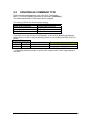
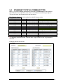
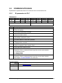
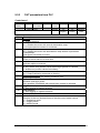
1
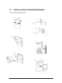
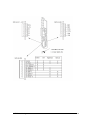
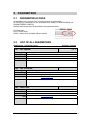
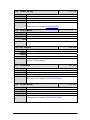
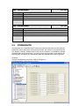
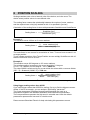
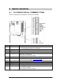
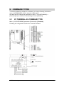
ATV71 POSITIONING
User manual
Document rev. 8
Manual comply to: ATV71 Positioning application V4.1.4
Disclaimer
The software described in this manual is sold or licensed “as is”. Should the program prove defective neither Schneider
Electric nor the distributor is responsible for the cost of any servicing, repair incidental or consequential damages resulting
from any defect in the software. Further, Schneider Electric reserves the right to revise this publication and to make changes
from time to time in the contents hereof without obligation to notify any person of such revision or changes.
ATV71 Positioning
2
Table of contents
1
INTRODUCTION .........................................................................................................................4
2
OVERVIEW...................................................................................................................................4
2.1
TERMINAL CONNECTIONS ........................................................................................................4
2.2
REFERENCE CHANNEL ..............................................................................................................4
2.3
STARTUP ..................................................................................................................................4
2.4
MOTOR CONTROL LAW ............................................................................................................4
2.4.1 Encoder on motor shaft ......................................................................................................4
2.4.2 Extern Encoder Function....................................................................................................4
3
INSTALLATION...........................................................................................................................5
3.1
INSTALLATION OF OPTION CARDS ............................................................................................5
3.2
24VDC .....................................................................................................................................6
3.2.1 Card powered by the drive .................................................................................................7
3.2.2 Card powered by external power supply ............................................................................7
3.3
INSTALLATION OF ENCODER BOARDS .......................................................................................8
4
POSITIONING MENU ...............................................................................................................11
4.1
5
MENU OVERVIEW ...................................................................................................................11
PARAMETERS ...........................................................................................................................12
5.1
5.2
5.3
PARAMETER ACCESS ..............................................................................................................12
LIST OF ALL PARAMETERS ......................................................................................................12
POWERSUITE .........................................................................................................................20
6
POSITION SCALING.................................................................................................................21
7
EXTERNAL ENCODER ............................................................................................................22
8
INPUTS / OUTPUTS...................................................................................................................23
8.1
9
I/O CONFIG FOR ALL COMMAND TYPES ..................................................................................23
COMMAND TYPES ...................................................................................................................24
9.1
I/O TERMINAL AS COMMAND TYPE ........................................................................................24
9.2
CANOPEN AS COMMAND TYPE................................................................................................26
9.3
COM.CARD OR MODBUS AS COMMAND TYPE ..........................................................................27
9.4
ETHERNET TCP/IP AS COMMAND TYPE .................................................................................28
9.5
COMMUNICATION BUS ...........................................................................................................29
9.5.1 IN parameters to PLC.......................................................................................................29
9.5.2 OUT parameters from PLC ..............................................................................................31
10
MODE SELECTION ..............................................................................................................33
10.1
10.2
10.3
10.4
POSITIONING (MODE 1) ..........................................................................................................33
JOGGING (MODE 2) ................................................................................................................34
HOMING MODE (MODE 3) ......................................................................................................35
BLENDING POSITIONING (MODE 4) ........................................................................................39
11
FIRST STARTUP....................................................................................................................41
12
ALARM NUMMER ................................................................................................................42
ATV71 Positioning
3
1
INTRODUCTION
ATV71 Positioning card is an option card with software that makes it possible to have
positioning functions with the drive ATV71. Example likes to manage absolute and
relative positioning movements. Functions as different homing modes and jogging
functions are also possible.
2
OVERVIEW
2.1
TERMINAL CONNECTIONS
Some inputs and outputs on the ATV71 have fixed functions. This is managed by the
positioning software. See chapter ”INPUTS / OUTPUTS” for more information.
2.2
REFERENCE CHANNEL
It’s possible to have 3 different reference channels.
Terminal:
Physical drive I/O with preset positions, speeds ,etc.
Com.card:
Communication card supported by ATV71 or the integrated Modbus.
CANopen:
Integrated CANopen port.
2.3
STARTUP
After a clean startup it’s necessary to make a homing. The software supports
different kind of homing modes. See chapter ”HOMING MODE” for more information.
2.4
2.4.1
MOTOR CONTROL LAW
Encoder on motor shaft
The motor control law should be selected to [FVC] Full Flux vector closed loop.
Encoder mounted direct on the motor shaft is the recommended solution.
This gives the most benefits like:
Full torque from 0Hz.
Better and faster brake logic control.
Better torque and speed accuracy.
See chapter 1.5 [Motor control] in ATV71 programming manual for more information
regarding FVC mode.
For vertical load this motor law is mandatory.
2.4.2
Extern Encoder Function
Use this function if the encoder is not mounted on the motor shaft.
Motor control law should be selected to [SVC U] or more preferred [SVC I] Flux
vector open loop.
This means that we don’t get any advantages from the encoder to have a better
torque or speed accuracy that we get if the encoder would be mounted on the motor
shaft.
Work good with horizontal movements with less performance requirements.
The encoder must be connected to a standard encoder board.
ATV71 Positioning
4
3
3.1
INSTALLATION
INSTALLATION OF OPTION CARDS
For ATV71 Positioning card and communication cards.
ATV71 Positioning
5
3.2
24VDC
ATV71 Positioning card needs 24VDC to terminal marked 24V to function.
Terminal
24V
COM
LI, LO, AI
and AO
Description
Power supply for the "Controller Inside" card, logic outputs and analog outputs.
If allowed by the power consumption table (for example if outputs are not being
used), the "Controller Inside" card can be powered by the 24 V power supply in the
drive.
If you are using an external power supply:
•The "Controller Inside" card should preferably be turned on before the drive.
However, the "Controller Inside" card must without fail be turned on no more than
2s after the drive is turned on.
Failure to follow this instruction locks the drive in card fault mode (ILF). This fault
cannot be reset, and the only way to acknowledge it is to turn off the drive.
Common ground and electrical 0V of the "Controller Inside" card power supply,
logic inputs, (LIxx), outputs (LOxx), analog inputs (AIxx) and analog outputs (AOxx).
This ground and electrical 0V are common with the drive ground and electrical 0V.
There is therefore no point in connecting this terminal to the 0V terminal on the
drive control terminals.
See chapter ”INPUTS/OUTPUTS” for those functions.
ATV71 Positioning
6
3.2.1
Card powered by the drive
If the power consumption is less than 200mA.
Example: Use of communication card as reference source and no outputs is used.
3.2.2
Card powered by external power supply
If the power consumption is higher than 200mA.
Example: Use of Terminal as reference source.
ATV71 Positioning
7
3.3
INSTALLATION OF ENCODER BOARDS
For all encoder board references.
ATV71 Positioning
8
ATV71 Positioning
9
ATV71 Positioning
10
4
4.1
POSITIONING MENU
MENU OVERVIEW
To be able to manage the new parameters for the positioning software there is a new
menu [1.14 POSITIONING].
From this menu you make every adjustment for your machine axis.
See chapter”PARAMETERS” for a full list of all available parameters for the
positioning application.
ATV71 Positioning
11
5
PARAMETERS
5.1
PARAMETER ACCESS
It’s possible from a superior PLC to read and write all parameters.
All “Read only” parameters is also accessible from menu [1.2 MONITORING] and
[6 MONITORING CONFIG.]
Address and Access level is described in the parameter table:
R = Read only
R/W = Read, Write
R/WS = Read, Write (writable without enable)
5.2
LIST OF ALL PARAMETERS
Displaycode - Parameter name
Address - Access
O01 - Act Speed
Description
Range
Default
Unit
Function
Actual speed
0 Ù 32767
Rpm
Actual motor/axis speed.
O02 - Act Position
Description
Range
Default
Unit
Function
ATV71 Positioning
6402 - R
Actual position
-32768 Ù 32767
usr (User unit, see Position scaling for more info)
Actual motor/axis position.
O03 - DistToGo
Description
Range
Default
Unit
Function
6401 - R
6403 - R
Distance to go
-32768 Ù 32767
usr (User unit, see Position scaling for more info)
Distance to go before reaching target position.
12
O04 - p_dif
Description
Range
Default
Unit
Function
6404 - R
Following Error
-32768 Ù 32767
usr (User unit, see Position scaling for more info)
Displays the relationship between actual position and profile
position.
O05 - ErrorNo.
6405 - R
Description Actual error number
Range 0 Ù 15
Default
Unit
Function Find more info in chapter “ALARM NUMBER”
O06 – Active Mode
6406 - R
Description Active mode
Range 0 Ù 4
Default
Unit
Function 0 = No mode
1 = Positioning mode
2 = Jogging mode
3 = Homing mode
4 = Blending mode (2 Speed positioning)
O08 - Command
Description
Range
Default
Unit
Function
Command and reference channel
Terminal (0), Com.Card (1), CANopen (2)
Terminal (0)
0 – Terminal (Physical In and Outputs.)
1 – Com.Card (Option Com card or the integrated Modbus port.)
2 – CANopen (Integrated CANopen port.)
O09 - HMmethod
Description
Range
Default
Unit
Function
ATV71 Positioning
6408 – R/WS
6409 – R/W
Homing method
1..5
1
Find more info in chapter”HOMING MODE”.
13
O10 - Home_speed
Description
Range
Default
Unit
Function
6410 – R/W
Speed for homing movement
4 Ù 3000
300
rpm
Speed for homing sequence.
Find more info in chapter”HOMING MODE”.
O11 - JOG_speed
Description
Range
Default
Unit
Function
Speed for jogging
1 Ù 3000
100
rpm
Speed for jogging sequence.
O12 - AI1 Adjust
Description
Range
Default
Unit
Function
Activate input AI1 to be a speed override adjustment.
0-100% of Target Speed.
ATV71 Positioning
6413 – R/WS
Numerator scale factor for user unit
0 Ù 65535
1
Motor rotation
Use to scale Usr (User units) to the axis geometry.
Find more info in chapter”POSITION SCALING”.
O14 - ScaleDenom
Description
Range
Default
Unit
Function
6412 – R/WS
Activate AI1 for speed override adjustment
No (0) Ù Yes (1)
No (0)
O13 - ScaleNum
Description
Range
Default
Unit
Function
6411 – R/W
6414 – R/WS
Denominator scale factor for user unit
0 Ù 65535
20
usr (User unit, see Position scaling for more info)
Use to scale Usr (User units) to the axis geometry.
Find more info in chapter”POSITION SCALING”.
14
O15 - ExtEncoder
Description
Range
Default
Unit
Function
Activate function External Encoder
No (0) Ù Yes (1)
No (0)
External Encoder function can be used to carry out direct position
measurement in the installation.
Find more info in chapter”EXTERNAL ENCODER”.
O16 - ExtEncNum
Description
Range
Default
Unit
Function
ATV71 Positioning
6418 – R/WS
Activate LI60 QuickStop function
No (0) Ù Yes (1)
Yes (1)
Activate hardware logic input LI60 - QuickStop function
O19 - KPp
Description
Range
Default
Unit
Function
6417 – R/WS
Denominator scale factor for external encoder function
0 Ù 65535
1
Motor rotations
Find more info in chapter”EXTERNAL ENCODER”.
O18 - HW_QuickStop
Description
Range
Default
Unit
Function
6416 – R/WS
Numerator scale factor for external encoder function
0 Ù 65535
100
Encoder pulses
Find more info in chapter”EXTERNAL ENCODER”.
O17 - ExtEncDenom
Description
Range
Default
Unit
Function
6415 – R/WS
6419 – R/W
Proportional gain factor for positioning loop
1 Ù 100
5
KPp good: The machine behavior is acceptable
KPp too great: overshooting of the mechanism, instability of the
motor control.
KPp too small: Slow response and to long time to get Target
Reached, very large following error
15
O21 - PLCRampAdj
Description
Range
Default
Unit
Function
Activate PLC ramp adjusting
No (0) Ù Yes (1)
No (0)
Activate access for PLC to write parameter Acceleration and
Deceleration from COM.SCANNER IN.
O22 - Acceleration
Description
Range
Default
Unit
Function
Rpm/s²
Acceleration ramp of the profile generator.
Rpm/s²
Deceleration ramp of the profile generator.
ATV71 Positioning
6424 – R/W
Multiplier for QuickStop ramp
100 Ù 30000
2000
Rpm/s²
Deceleration ramp of the profile generator on a Quick Stop
command.
O25 - InPosWin
Description
Range
Default
Unit
Function
6423 – R/W
Deceleration ramp
100 Ù 30000
1000
O24 - QStopRamp
Description
Range
Default
Unit
Function
6422 – R/W
Acceleration ramp
100 Ù 30000
1000
O23 - Deceleration
Description
Range
Default
Unit
Function
6421 – R/W
6425 – R/W
In Position Window
0 Ù 32767
1
usr (User unit, see Position scaling for more info)
Target position window for report of Target reached
To get Target Reached both InPosWin and InPosTime must be
true.
16
O26 - InPosTime
Description
Range
Default
Unit
Function
In Position Time
1 Ù 3000
20
Ms (milliseconds)
Target position window time for report of Target reached
To get Target Reached both InPosWin and InPosTime must be
true.
O27 - RefPointPosition
Description
Range
Default
Unit
Function
ATV71 Positioning
6429 – R/W
Activate hardware limit switches
None (0), N-Open (1), N-Closed (2)
None
0, None: no limit switches
1, N-Open: 2 limit switches with normal open contact
2, N-Closed: 2 limit switches with normal closed contact
O30 - IOsigREF
Description
Range
Default
Unit
Function
6428 – R/W
Max permissible following error
1 Ù 65535
100
usr (User unit, see Position scaling for more info)
If following error is greater that this value the drive stops on
Freewheel and report Alarm number 1.
O29 - IOsigLIMx
Description
Range
Default
Unit
Function
6427 – R/W
Position to set on a finished Homing procedure
-32768 Ù 32767
0
usr (User unit, see Position scaling for more info)
This value is copied to Actual Position on a finished Homing
procedure.
Find more info in chapter”HOMING MODE”.
O28 - P_maxDiff
Description
Range
Default
Unit
Function
6426 – R/W
6430 – R/W
Activate reference switch
None (0), N-Open (1), N-Closed (2)
N-Open (1)
0, None: no reference switch
1, N-Open: reference switch with normal open contact
2, N-Closed: reference switch with normal closed contact
17
O31 - SW_Limits
Description
Range
Default
Unit
Function
Activate software limits
No (0), Yes (1)
No (0)
0, No: no software limits.
1, Yes: software limits in both directions is monitored.
Config parameter SW_LimN and SW_LimP to your limit values.
O32 - SW_LimN
Description
Range
Default
Unit
Function
ATV71 Positioning
6434 – R/W
Extract distance from homing switch
0.0 Ù 50.0
0.0
Motor rotation
Find more info in chapter ”HOMING MODE”.
O35 - AdvScaling
Description
Range
Default
Unit
Function
6433 – R/W
Max position in positive direction
-32768 Ù 32767
32767
usr (User unit, see Position scaling for more info)
If a target position is sent outside this position the Alarm number 3
gets active.
O34 - HMdistOut
Description
Range
Default
Unit
Function
6432 – R/W
Max position in negative direction
-32768 Ù 32767
-32768
usr (User unit, see Position scaling for more info)
If a target position is sent outside this position the Alarm number 2
gets active.
O33 - SW_LimP
Description
Range
Default
Unit
Function
6431 – R/W
6435 – R/WS
Activate advanced scaling
No (0), Yes (1)
No (0)
Activate parameters ScaleNumHw and ScaleDenomHw.
This parameters complement ScaleNum and ScaleDenom to be
able to use bigger values then 65535 in the scaling of [Usr - User
unit].
18
O36 - ScaleNumHw
Description
Range
Default
Unit
Function
Numerator 2 scale factor for user unit
0 Ù 65535
0
Motor rotations
Use to scale Usr (User units) to the axis geometry.
Find more info in chapter”POSITION SCALING”.
O37 - ScaleDenomHw
Description
Range
Default
Unit
Function
Motion Task number to adjust the following parameters:
Position, Speed, Acceleration, Deceleration
ATV71 Positioning
6441 – R/WS
Position for motion task 1..15
-32768 Ù 32767
0
usr (User unit, see Position scaling for more info)
Position for motion task number (SetMotionTask).
O42 - Speed
Description
Range
Default
Unit
Function
6440 – R/WS
The Motion task number to adjust
0 Ù 15
0
O41 - Position
Description
Range
Default
Unit
Function
6437 – R/WS
Denominator 2 scale factor for user unit
0 Ù 65535
0
usr (User unit, see Position scaling for more info)
Use to scale Usr (User units) to the axis geometry.
Find more info in chapter”POSITION SCALING”.
O40 - SetMotionTask
Description
Range
Default
Unit
Function
6436 – R/WS
6442 – R/WS
Speed for motion task 1..15
0 Ù 6000
0
rpm
Speed for motion task number (SetMotionTask).
19
O43 - Acceleration
Description
Range
Default
Unit
Function
Acceleration for Motion Task 1..15
100 Ù 30000
1000
Rpm/s²
Acceleration for motion task number (SetMotionTask).
O44 - Deceleration
Description
Range
Default
Unit
Function
5.3
6443 – R/WS
6444 – R/WS
Deceleration for Motion Task 1..15
100 Ù 30000
1000
Rpm/s²
Deceleration for motion task number (SetMotionTask).
POWERSUITE
All parameter are compatible with PowerSuite software. But there’s a limit with the
parameter names and units. As the picture shows, the names is only described as
Oxx display numbers. And the units is not correct. However it’s possible to change
the parameters with PowerSuite. You have to see the parameter value without the
decimal point, but when you change the value the decimal point must be present.
Example:
Change Acceleration value from 1000 to 3500rpm/s².
O22 Acceleration: 100.0 change to 350.0
ATV71 Positioning
20
6
POSITION SCALING
Scaling translates user units to internal units of the device, and vice versa. The
device saves position values in user-defined units.
The scaling factor creates the relationship between the number of motor rotations
and the required user units [usr] needed for this. It is specified in [rev/usr].
Calculation of the scaling factor is done with parameters ScaleNum and ScaleDenom
ScaleNum [rev]
ScaleDenom [usr]
Scaling factor =
Example 1:
The machine moves 100mm on 2 motor rotations.
Scaling factor =
2
100
motor rotations [rev]
user units [usr]
The scale factor is now correct for a resolution of 1mm. To move 1mm we send 1 usr
as target position.
To get a better resolution of the Target Position we can multiply ScaleDenom with 10.
Now the resolution is set to 0,1mm.
Example 2:
The machine moves 360 degrees on 2.5 motor rotations.
The smallest position increment to be moved should be 0.1 degree.
2,5 rev * 10 = 25 rev and 360 degree * 100 = 36000 usr
The value 36000 is a little too big so we can divide the values with a common divider.
(250 / 5) = 5 rev and (36000 / 5) = 7200 usr
Scaling factor =
25
motor rotations [rev]
36000
user units [usr]
The scale factor is now correct. To move 0.1 degree we send 1 usr as target position.
Using bigger scaling values then 65535:
If you need bigger values than 65535 for scaling, first try to find the biggest common
divider. If this is not enough, you can activate “AdvScaling” parameter.
The 2 new parameters ScaleNumHw and ScaleDenomHw are used as a
complement together with standard ScaleNum and ScaleDenom parameters.
The new parameters represent the high word in a double word. And the default
parameters represent the low word in a double word.
Please contact Schneider Electric for help calculating this parameters correct.
ATV71 Positioning
21
7
EXTERNAL ENCODER
This external encoder function can be used to carry out direct position measurement
in the installation (actual position).
Remember that the external encoder has no influence on the speed and current
regulators inside the drive. No vertical load is allowed.
Activate with parameter “ExtEncoder” = Yes
The encoder is connected to one of the standard encoder boards available.
You use the regular scaling parameters ScaleNum and ScaleDenom for User units.
The new parameters for external encoder scaling is to define the pulses from the
external encoder to motor rotations.
Calculation of the scaling factor is done with parameters ExtEncNum and
ExtEncDenom.
ExtEncNum [EncInc]
ExtEncDenom [rev]
Scaling factor =
Example:
The external encoder has a resolution of 1024 inc/rev.
One turn of the encoder is exactly 3 motor rotations.
Scaling factor =
1024 encoder pulses [EncInc]
3 motor rotations [rev]
The scale factor is now set correct.
See chapter”POSITION SCALING” for more information to scale your user units
correct.
ATV71 Positioning
22
8
INPUTS / OUTPUTS
8.1
I/O CONFIG FOR ALL COMMAND TYPES
This I/O configuration is standard for all reference channels.
Input
LI52
Name
Halt
Function
0->1: Brakes the motor with normal deceleration ramp
1->0: Interrupted movement is continued
LI54
Ref. Switch
Reference switch
LI58
LIMP
Hardware limit switch in positive direction
LI59
LIMN
Hardware limit switch in negative direction
LI60
QuickStop
1->0: Brakes the motor with deceleration ramp defined in
parameter ”QStopRamp”
Interrupted movement is loosed.
Output Name
Function
LO51
Drive Fault
A drive fault is present. Drive is disabled.
(Find more info in chapter ”ALARM NUMBER”)
LO52
Target Reached Movement finished and has reached the InPosWin
LO53
Standstill
Motor at standstill
LO54
HaltActive
A halt command is active.
LO55
Ref OK
A Homing has been done correct after startup.
LO56
QuickStopActive QuickStop is activated.
Clear with Fault Reset.
Interrupted movement is loosed.
ATV71 Positioning
23
9
COMMAND TYPES
To activate positioning software it’s mandatory to change following parameter in
menu 1.6 [COMMAND] -> [Ref.1 channel] = PLC card
And after that you change the parameter in menu 1.14 [POSITIONING] ->
[Command] to your choice of Command type for the positioning.
9.1
I/O TERMINAL AS COMMAND TYPE
Menu [1.14 POSITIONING] parameter [Command] = [Terminal].
Following I/O configuration is active for Terminal command.
ATV71 Positioning
24
Input
LI51
LI52
Name
Enable
Halt
LI53
LI54
LI55
LI56
LI57
LI58
LI59
LI60
Fault Reset
Setpoint
Ref. Switch
Relative
Homing
LIMP
LIMN
QuickStop
LI1
Jog +
LI2
Jog LI3..LI6 Motion Task bit x
Function
0->1: Enable the drive
0->1: Brakes the motor with normal deceleration ramp
1->0: Interrupted movement is continued
Clear an active alarm or a drive fault
0->1: Start Positioning command or Homing
Reference switch
Activate relative movement
Activate homing mode. Starts with Setpoint
Hardware limit switch in positive direction
Hardware limit switch in negative direction
1->0: Brakes the motor with deceleration ramp defined in
parameter ”QStopRamp”
Interrupted movement is loosed
Start Jogging in positive direction
Start Jogging in negative direction
Activate a Motion Task number. Binary format
Motion Task bit 0 = 1
Motion Task bit 1 = 2
Motion Task bit 2 = 4
Motion Task bit 3 = 8
Example:
Motion Task 1 = bit 0 = no.1
Motion Task 2 = bit 1 = no.2
Motion Task 7 = bit 0 + bit 1 + bit 2 = no.7
Motion Task 10 = bit 1+ bit 3 = no.10
AI1
AI1 Speed Adj.
Output
LO51
Name
Drive Fault
LO52
Target Reached
LO53
LO54
LO55
LO56
Standstill
HaltActive
Ref OK
QuickStopActive
ATV71 Positioning
Activate input AI1 to be a speed override adjustment.
0-100% of Target Speed
Function
A drive fault is present. Drive is disabled
(Find more info in chapter ”ALARM NUMBER”)
0: Target position not reached
1: Target position reached
Motor at standstill. Motor speed <15rpm
A halt command is active.
Drive has valid reference point
QuickStop has activated. Clear with Fault Reset.
Interrupted movement is loosed.
25
9.2
CANOPEN AS COMMAND TYPE
PDO3 should be activated and used in the PLC Configuration.
Menu [1.14 POSITIONING] parameter [Command] = [CANopen].
The object inside PDO3 is fixed and can’t be changed.
The object in PDO3 has the following meaning.
Transmit PDO3
Receive PDO3
Status word Positioning
Control word Positioning
Actual Position
Target Position
Actual Speed
Target Speed
Profile Position
Reserved
If you want to use the function ”PLCRampAdj” or the mode 4 “Blending positioning
mode” then you have to map the following object in to a free Receive PDO (PDO1 or
PDO2).
Receive PDOx
Obj. Idx. Sub. Idx. Parameter description
Function that comes active
2061
44
Com Scan Out6 val.
*Acceleration / **Target Position 2
2061
45
Com Scan Out7 val.
*Deceleration / **Target Speed 2
*Acceleration and Deceleration are used if parameter ”PLCRampAdj” = Yes
**If ”Blending positioning mode” is active then Target Position 2 and Target Speed 2
are used.
ATV71 Positioning
26
9.3
COM.CARD OR MODBUS AS COMMAND TYPE
Menu [1.14 POSITIONING] parameter [Command] = [Com.card] must be selected.
The I/O Scanner table in ATV71 is used for reference command.
For Ethernet card see chapter ”Ethernet Modbus TCP/IP as command type” for info.
Following table shows the automatic mapping.
Word Modbus I/O scanner input
Modbus I/O Scanner output
Address
Address
1
12741
Status word CiA402
12761
Control word CiA402
Not in use with positioning
Not in use with positioning
2
12742
Output velocity CiA402
12762
Speed Setpoint CiA402
Not in use with positioning
Not in use with positioning
3
12743
Status word Positioning
12763
Control word Positioning
4
12744
Actual Position
12764
Target Position
5
12745
Actual Speed
12765
Target Speed
6
12746
Profile Position
12766
*Acceleration / **Target Position 2
7
12747
reserved
12767
*Deceleration / **Target Speed 2
8
12748
reserved
12768
reserved
*Acceleration and Deceleration are used if parameter ”PLCRampAdj” = Yes
**If ”Blending positioning mode” is active then Target Position 2 and Target Speed 2
are used.
ATV71 Positioning
27
9.4
ETHERNET TCP/IP AS COMMAND TYPE
Menu [1.14 POSITIONING] parameter [Command] = [Com.card] must be selected.
The IO Scanner in the Ethernet card must be commissioned with the right objects.
This can be done with Powersuite or the web server.
The following objects should be written into the IO Scanner table.
Output Parameters
Parameter
Address Description
Function that becomes active
NC3
12763 Com Scan Out3 val. Control Positioning
NC4
12764 Com Scan Out4 val. Target Position (usr)
NC5
12765 Com Scan Out5 val. Target Speed (rpm)
NC6
12766 Com Scan Out6 val. *Acceleration / **Target Position 2
NC7
12767 Com Scan Out7 val. *Deceleration / **Target Speed 2
Input Parameters
Parameter
Address Description
Function that becomes active
NM3
12743 Com Scan In3 val.
Status word Positioning
NM4
12744 Com Scan In4 val.
Actual Position
NM6
12745 Com Scan In5 val.
Actual Speed
NM6
12746 Com Scan In6 val.
Profile Position
*Acceleration and Deceleration are used if parameter ”PLCRampAdj” = Yes
**If ”Blending positioning mode” is active then Target Position 2 and Target Speed 2
are used.
Example with the web server:
ATV71 Positioning
28
9.5
COMMUNICATION BUS
Explanation for parameters that is for command from communication bus.
9.5.1
IN parameters to PLC
Statusword
Bit 7
Reference
OK
Bit 15
Bit 6
Standstill
Bit 5
Target
Reached
Bit 14
Bit 13
Error Number
Bit 4
Fault
Active
Bit 3
QuickStop
Active
Bit 12
Bit 11
Bit 2
Halt
Active
Bit 1
Setpoint
Acknowledge
Bit 0
Operation
Enabled
Bit 10
Bit 9
Active Mode
Bit 8
Bit
0
Description
Operation Enabled
1: Drive is enabled
1
Setpoint acknowledge
1: New target positioning accepted
2
Halt active
1: Halt command is active
3
QuickStop active
1: QuickStop command is active
4
Fault active
1: An active alarm or drive fault is present.
5
Target reached
1: Target position reached
6
Standstill
1: Motor at standstill. Motor speed<15rpm
7
Reference OK
1: Drive has valid reference point
8..11 Active Mode
Extract this 4 bits to a decimal format to get the correct mode number
1 = Positioning mode
2 = Jogging mode
3 = Homing mode
12..15 Error number
Extract this 4 bits to a decimal format to get the correct alarm number
Read chapter ”ALARM NUMBER” for more info.
Actual Position
Range -32768 Ù 32767
Unit usr (see Position scaling for more info)
Function Actual motor/axis position.
ATV71 Positioning
29
Actual Speed
Range 0 Ù 32767
Unit Rpm
Function Actual motor/axis speed.
Profile Position
Range -32768 Ù 32767
Unit usr (see Position scaling for more info)
Function Actual motor position of the axis.
Profil position is the theoretical position from the position generator
that the motor should follow.
Following error = Profil position – Actual position.
ATV71 Positioning
30
9.5.2
OUT parameters from PLC
Controlword
Bit 7
Dimension
Setting
Bit 15
Bit
0
1
2
3
4
5
6
7
8
9
10
11
12..15
Bit 6
Setpoint
Bit 5
Set
Immediately
Bit 14
Bit 13
Mode Selection
Bit 4
Relative
Bit 3
Fault
Reset
Bit 2
QuickStop
Bit 1
Halt
Bit 0
Enable
Bit 12
Bit 11
reserved
Bit 10
Jog
Negative
Bit 9
Jog
Positive
Bit 8
Reference
switch
Description
Enable
1: Enable the drive
Halt
0->1: Brakes the motor with normal deceleration ramp
1->0: Interrupted movement is continued
QuickStop
0->1: Brakes the motor with deceleration ramp defined in parameter
”QStopRamp”
Interrupted movement is loosed.
Fault Reset
Clear an active alarm or a drive fault
Relative
Activate relative movement
Set Immediately
0: only enable new position values when target position is reached
1: enable new position values immediately
Setpoint
0->1: Start Positioning command or Homing.
Dimension setting
1: Change temporary the Homing method to no.5
Reference switch
Simulate reference switch.
Only possible if RefSwitch with normal open contact is activated.
Jog Positive
1: Start jogging in positive direction
Jog Negative
1: Start jogging in negative direction
Reserved
Mode Selection
Pack the 4 bits to a decimal format to set the correct mode number
1 = Positioning mode
2 = Jogging mode
3 = Homing mode
ATV71 Positioning
31
Target Position
Range -32768 Ù 32767
Unit usr (see Position scaling for more info)
Function The destination position is different depending if absolute or
relative positioning is used.
Target Speed
Range 0 Ù 32767
Unit Rpm
Function Max speed that the profile generator can use.
Target Position 2
Range -32768 Ù 32767
Unit usr (see Position scaling for more info)
Function Only active if Mode Selection = 4, Blending Positioning Mode.
Target Speed 2
Range 0 Ù 32767
Unit Rpm
Function Only active if Mode Selection = 4, Blending Positioning Mode.
Acceleration
Range 100 Ù 30000
Unit Rpm/s²
Function ”PLCRampAdj” = Yes
Acceleration ramp of the profile generator.
Deceleration
Range 0 Ù 32767
Unit Rpm/s²
Function ”PLCRampAdj” = Yes
Deceleration ramp of the profile generator.
ATV71 Positioning
32
10 MODE SELECTION
It exists different mode selections depending of the operation to execute.
If the command is a communication bus the mode selection is done from the
Controlword.
Or if the command is I/O Terminal the mode selection is done with logical inputs.
10.1 POSITIONING (MODE 1)
10.1.1
I/O Terminal
With I/O Terminal as the command channel the positioning mode is automatically
chosen if no other modes is active like the homing or jogging mode.
The target position to reached is chosen with the logical inputs LI3 – LI6 in binary
format. Configuring positions 1 – 15 is done in menu [1.14 POSITIONING] parameter
[SetMotionTask]. See chapter Parameters for the explanation of MotionTask
parameters.
Example:
To start a positioning to MotionTask 2 we set input LI4 = 1.
Then we set input LI55 - Setpoint = 1. The confirmation that the positioning is started
is when output LO52 – Target Reached goes low. When the positioning is finished
the output LO52 – Target Reached goes high again.
10.1.2
Communication bus
With command channel set to a supported communication bus the Controlword bit 12
– 15 is used to change the mode to positioning.
Example:
Set Mode Selection = 1 (Bit 12) in Controlword.
Go to absolute value 2000usr with a speed of 1500rpm.
Parameter Target Position = 2000 and Target Speed = 1500
Set Setpoint (bit 6) = 1 in Controlword. Wait to get back SetpointACK (bit 1) = 1 from
Statusword. Then you now that your values are correct and accepted. Also Target
Reached goes low when the positioning start and you now that the positioning is
done when Target Reached goes high again.
ATV71 Positioning
33
10.2 JOGGING (MODE 2)
10.2.1
I/O Terminal
With I/O Terminal as the command channel the jogging mode is automatically
chosen if no other mode is in progress and you set either input LI1 Jog Positive or
LI2 Jog Negative.
10.2.2
Communication bus
With command channel set to a supported communication bus the Controlword bit 12
– 15 is used to change the mode to jogging.
Example:
Set Mode Selection = 2 (Bit 13) in Controlword.
To jog in positive direction you set and hold bit 9 in Controlword.
And to jog in negative direction you set and hold bit 10 in Controlword.
The jogging movement is stopped as soon as you set the bits to low state.
ATV71 Positioning
34
10.3 HOMING MODE (MODE 3)
In homing mode, an absolute scale reference of the motor position at a defined axis
position is established. Referencing can be carried out by a homing movement or by
dimension setting.
10.3.1
I/O Terminal
With I/O Terminal as the command channel the homing mode is activated with input
LI57 – Homing. First you should have to set the right homing procedureyou’re your
machine with parameter [HMmethod] in menu [1.14 POSITIONING].
Then you start the homing sequence with input LI55 – Setpoint.
10.3.2
Communication bus
With command channel set to a supported communication bus the Controlword bit 12
– 15 is used to change the mode to homing.
Example:
Set Mode Selection = 3 (bit 12 and Bit 13) in Controlword.
Start the homing sequence with Setpoint (bit 6) = 1 in Controlword.
The homing sequence is done when Reference OK (bit 7) goes high.
ATV71 Positioning
35
10.3.3
Homing Method 1
With method 1 the homing is carried out with movement to negative hardware limit
switch.
1. Start of homing to LIMN with the speed of parameter Home_Speed.
2. The axis hits the LIMN and starts to extract in positive direction with ¼ of
Home_Speed.
On falling edge of the switch the parameter RefPointPosition is written to
Actual Position and the reference is OK.
3. The motor stops when the parameter HMdistOut is fulfilled. This distance is to
make sure the axis stop it not to near the LIMN switch.
10.3.4
Homing Method 2
Method 2 is similar to the method 1 with the different of a start to move to the positive
hardware limit switch.
ATV71 Positioning
36
10.3.5
Homing Method 3
With method 3 the homing is carried out with movement to a reference switch in
negative direction.
1. Start of homing to REF with the speed of parameter Home_Speed.
2. The axis hits the REF and starts to extract in positive direction with ¼ of
Home_Speed.
On falling edge of the switch the parameter RefPointPosition is written to
Actual Position and the reference is OK.
3. The motor stops when the parameter HMdistOut is fulfilled.
Remark: If the machine is equipped with hardware limit switches and the axis is on
the wrong side of the reference switch. The axis turns around when it hits the LIMx
switch and continues to search the REF switch.
10.3.6
Homing Method 4
Method 4 is similar to the method 3 with the different of a start to move to the positive
direction.
ATV71 Positioning
37
10.3.7
Homing Method 5
With method 5 the user can make a homing without movements. A so called
“Dimension setting”. Any active position deviation is also retained.
The reference position is adjustable in fieldbus command because the value in ”Target
Position” is written as new position. And with fieldbus command it’s possible to shift to
method 5 with bit 7 in control word so you can have another method as default type.
In Terminal command the parameter RefPointPosition is written as new position.
Example:
It can be used to make an endless movement in one direction.
To not overrun the internal max position of 2147483647 Inc we make a homing with
method 5 and write the actual position to zero after a specific position.
1.
An absolute movement of 2000 usr is carried out.
2.
When the axis has reached its final destination we send a homing
command and the actual position gets the new value.
3.
Then we start a new absolute movement of 2000 usr.
With this cycle we can carry out a position in an endless loop without get a position
overrun.
ATV71 Positioning
38
10.4 BLENDING POSITIONING (MODE 4)
Blending Positioning is not working with I/O Terminal as command channel.
It’s only active with communication bus as command channel.
Set Mode Selection = 4 in Controlword to activate Blending Positioning mode.
With Blending Positioning mode it’s possible to trigger one positioning sequence that
have an automatically speed change on a predefined position point.
You have to set one speed to define the starting speed. And one speed as the
switching speed. Along with the speed you also define a destination position and a
switching position.
Some standard OUT parameters from the PLC get new functions
Standard function
Controlword Positioning
Target Position
Target Speed
*Target Position 2
*Target Speed 2
New funktion
none
Destination position
Starting speed
Switching position
Switching speed
*parameters that changes with blending positioning mode.
Example 1:
Switching position
800usr
0usr
Destination position
1000usr
Speed
Starting speed
1500
1000
Switching speed
500
0
Time
Start with a absolute destination position to 1000usr with a starting speed of
1500rpm.
Switching position set to 800usr and switching speed to 500rpm.
ATV71 Positioning
39
Example 2:
Switching position
800usr
0usr
Quickstop
on a sensor
Destination position
1000usr
Speed
Starting speed
1500
1000
Switching speed
500
0
Time
With this example we will stopp on a sensor before we reach the destination position.
The destination position is now a safety position. If we reach this point the sensor is
mailfunction.
1. Start with an absolute destination position to 1000usr with a starting speed of
1500rpm.
Switching position is set to 800usr with a switching speed of 500rpm.
2. Quickstop command is triggered from a sensor an activated with bit 2 in
Controlword skickas efter att en givare har påverkats.
The destination position after quickstop is around 900usr.
ATV71 Positioning
40
11 FIRST STARTUP
Here is a quick help with points that can help you with the first startup.
The quick help assume that all parameters is adjusted with the Graphic Terminal and
that no parameters have been adjusted since factory setting.
1. Adjust all parameters for motor data in menu [1.1 SIMPLY START].
2. Make an auto tuning in menu [1.1 SIMPLY START]
3. Adjust parameters in menu [1.4 MOTOR CONTROL] for the encoder.
Parameter EnS – [Encoder type] and PGI – [Number of pulses].
4. Change in menu [1.6 COMMAND], Parameter Fr1 – [Ref.1 channel] = [HMI].
5. Adjust in menu [1.3 SETTINGS] parameters [Acceleration] and [Deceleration]
to values that is suitable for manual movement of the machine.
6. Make a test run from the Graphical Terminal and see that the machine moves
in positive direction with a positive speed reference.
If not, change the phase rotation for the motor. This can easily be done with
parameter PHr – [Output Ph rotation] in menu [1.4 MOTOR CONTROL].
7. Go to menu [1.4 MOTOR CONTROL] and activate [Encoder check] = Yes.
Make a manual movement with at least 10Hz and at the same time check the
status of parameter [Encoder check]. If the parameter change to “Done” the
encoder rotation is correct. But if the drive trips in “Encoder fault” the rotation
of the pulses is incorrect. Change place with cable marked A and Ā on the
encoder board and make the encoder check procedure again.
8. Adjust the following parameters in menu [1.4 MOTORSTYRNING]:
Encoder mounted on the motor shaft: Ctt – [Motor control type] = [FVC]
Encoder mounted after the gearbox: Ctt – [Motor control type] = [SVC I]
9. Now make some more test run manually from the Graphic Terminal and see if
the axis moves without any strange vibrations and currents.
If the axis have tendency to vibrate adjust the parameter SPG – [Speed prop.
gain] in menu [1.3 SETTINGS]. Decrease the value in steps until the
vibrations disappear.
10. Adjust in menu [1.6 COMMAND], Parameter [Ref.1 channel] = [PLC card]
11. Adjust in menu [1.14 POSITIONING], all parameters that is relevant for the
machine. See chapter “PARAMETERS”.
12. Now the drive is ready to be tested from the command source that you have
chosen in menu [1.14 POSITIONING] – Parameter [Command].
ATV71 Positioning
41
12 ALARM NUMMER
When a alarm is triggered from positioning application or the drive itself the alarm is
showing up on the graphic terminal with a describing help text (F1 button).
All alarm makes the drive go into freewheel stop.
Alarm number
1. Following error
Description
On first commissioning the limit P_maxDiff should be adjusted so that the
value is minimum 20% above the actual p_Dif on maximum speed.
For most reason when this alarm gets active it’s that the motor don’t have
the torque to follow the profile generator.
2. Negative
software limit
3. Positive
software limit
4. Positive
hardware limit
5. Negative
hardware limit
6. Homing is not
performed
14. External
Encoder fault
A target position is command outside the negative software limit.
15. Drive fault
Drive fault activated.
See the graphic display for more description.
Or read out the parameter Altivar fault code:
Logical address: 7121
CANopen index: 2029/16
ATV71 Positioning
A target position is command outside the positive software limit.
Positive hardware limit switch have been activated
Negative hardware limit switch have been activated
Homing procedure have not been done correctly yet.
Fault on the external encoder signals. The pulses coming from external
encoder are not in the expected interval. Check encoder wiring and
coupling.
If the alarm sets on first commissioning then it’s probably wrong scale
factor for external encoder function.
42