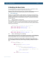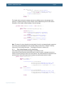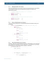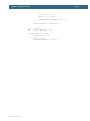
1
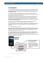
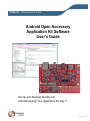
AOAA Kit – Software User’s Guide Copyright 2012 © Embedded Artists AB Android Open Accessory Application Kit Software User’s Guide Get Up-and-Running Quickly and Start Developing Your Application On Day 1! EA2-USG-1201 Rev A AOAA Kit – Software User’s Guide Page 2 Embedded Artists AB Davidshallsgatan 16 211 45 Malmö Sweden [email protected] http://www.EmbeddedArtists.com Copyright 2012 © Embedded Artists AB. All rights reserved. No part of this publication may be reproduced, transmitted, transcribed, stored in a retrieval system, or translated into any language or computer language, in any form or by any means, electronic, mechanical, magnetic, optical, chemical, manual or otherwise, without the prior written permission of Embedded Artists AB. Disclaimer Embedded Artists AB makes no representation or warranties with respect to the contents hereof and specifically disclaim any implied warranties or merchantability or fitness for any particular purpose. Information in this publication is subject to change without notice and does not represent a commitment on the part of Embedded Artists AB. Feedback We appreciate any feedback you may have for improvements on this document. Please send your comments to [email protected]. Trademarks All brand and product names mentioned herein are trademarks, services marks, registered trademarks, or registered service marks of their respective owners and should be treated as such. Copyright 2012 © Embedded Artists AB AOAA Kit – Software User’s Guide Page 3 Table of Contents 1 Document Revision History 5 2 Introduction 6 2.1 Demo Applications – Overview 6 2.2 Prerequisites 9 2.2.1 Software 9 2.2.2 Hardware 9 2.3 ESD Precaution 10 2.4 General Handling Care 10 2.5 Code Read Protection 10 2.6 Other Products from Embedded Artists 10 2.6.1 Design and Production Services 10 2.6.2 OEM / Education / QuickStart Boards and Kits 11 3 Demos 3.1 AOA Basic 12 3.1.1 Setup 12 3.1.2 Alternative Setup 12 3.1.3 Running the Demo 13 3.2 AOA CAN 13 3.2.1 Setup 15 3.2.2 Running the Demo 15 3.3 AOA XBee 16 3.3.1 Setup 17 3.3.2 Alternative Setup 18 3.3.3 Running the Demo 18 3.4 FreeRTOS 19 3.4.1 Setup 19 3.4.2 Running the Demo 19 3.5 Web Server 19 3.5.1 Setup 19 3.5.2 Running the Demo 20 4 Guides 21 4.1 Installing Suggested Android Application 21 4.2 Setting up Android Projects 22 4.3 Setting up Projects in LPCXpresso 23 4.4 Debugging a Project in LPCXpresso 26 4.5 Debugging an Android Application 27 4.6 Preparing the Android Device 29 5 Software packages 5.1 Copyright 2012 © Embedded Artists AB 12 The aoa_board_xxxxxx.zip 32 32 AOAA Kit – Software User’s Guide Page 4 5.2 The aoa_board_binaries_xxxxxx.zip 33 5.3 The aoa_can_node_xxxxxx.zip 33 5.4 The android_apps_xxxxxx.zip 33 5.5 The xpr_1769_bb_xbee_node_xxxxxx.zip 33 6 Modifying the Basic Demo 6.1 Add a New Message 35 6.1.1 Message Identifier in the Android App 35 6.1.2 Receive a New Message in the Android App 35 6.1.3 Send a New Message from the Android App 36 6.1.4 Message Identifier in the Accessory 37 6.1.5 Receive a New Message in the Accessory 37 6.1.6 Send a New Message from the Accessory 37 7 Further Information Copyright 2012 © Embedded Artists AB 35 39 AOAA Kit – Software User’s Guide Page 5 1 Document Revision History Revision Date Description PA1 2012-02-27 First version. PA2 2012-02-28 Updated after review PA3 2012-02-29 Reorganized chapters to improve readability PA4 2012-03-06 Preliminary release Copyright 2012 © Embedded Artists AB AOAA Kit – Software User’s Guide Page 6 2 Introduction Thank you for buying The Android™ Open Accessory Application Kit from Embedded Artists. For the rest of the document the term Android Open Accessory will be written out as AOA. The kit (hardware and software) will be called The AOAA Kit, for short. When referring to just the hardware the term AOAA Board will be used. The kit has been developed by Embedded Artists in close cooperation with NXP. It contains two microcontrollers from NXP, the LPC1769 (Cortex-M3 core) and LPC11C24 (Cortex-M0 core). The two microcontrollers are connected via a CAN network. Embedded Artists’ AOAA Kit lets you get up-and-running with AOA experiments immediately. It is a standalone platform for evaluation and prototyping electronic accessories for Google’s Android operating system. The AOAA Board is also suitable for experimenting with CAN, Ethernet and RF networks. The AOAA Board has been designed for evaluation and is not designed for final integration into consumer or industrial end-products. This document is a User’s Guide that primarily describes the software design of the AOAA Kit demonstration applications. The hardware design is addressed in another document. It is recommended that the reader has some basic knowledge about C programming and Android App development. A good source for Android App development is the Android Developers Guide, see reference [6]. 2.1 Demo Applications – Overview Android Open Accessory allows connecting Accessories to an Android device – typically a phone or tablet. The Accessory and Android device communicates over USB. The Accessory has to implement a USB Host interface, while the Android acts as a USB client (also called USB Device). For more information about Android Open Accessory, see [3]. From a software perspective, this means that the Accessory must implement a USB Host interface. There must also be two applications, one on the Accessory and one on the Android device. The two applications communicate over a custom defined protocol. AOA leaves this protocol open. The applications have complete freedom in defining the protocol between them and to create functionality that supports the application in the best way. Android Device Android Accessory Device Figure 1 – Basic Android Accessory Use Cases with Communication Protocol Copyright 2012 © Embedded Artists AB Protocol between Android device and Accessory. USB is only transport layer. Protocol is completely open for definition and can be adapted to specific requirements of the applications. AOAA Kit – Software User’s Guide Page 7 There are three AOA demo applications that can be downloaded from the Embedded Artists support page. The AOAA Board is not pre-loaded with any of these demo applications. The reason for this is that the applications are continuously updated and a pre-loaded application would quickly become outdated. This section gives an overview of the demos. For more information about how to work with the demos please read chapter 3 . The three AOA demo applications are: 1. An application that allows controlling and monitoring the AOAA Board from an Android device. The idea behind this (basic) demo is to have a simple and clean implementation that is easy to understand both from the Android application point of view and the software running on the Accessory (LPC1769). There is no fancy user interface on the Android side and not all peripherals on the AOAA Board are accessible. This basic implementation is a good starting point for adding more functionality. The applications show how to move data in both directions; from Android device to the Accessory and the other way around. The LPC11C24 is not used in this demo. 2. A network oriented demonstration application; the Accessory (LPC1769) manages nodes in a CAN network and present information from the nodes (LPC11C24) on the Android device. The CAN nodes can be controlled and monitored from the Android device. The Accessory detects when CAN nodes are connected and/or removed. The Android application is a little bit more advanced than in the first demo application. 3. A network oriented demonstration application; the Accessory (LPC1769) manages nodes in a wireless network and presents information from the nodes on the Android device. The wireless nodes can be controlled and monitored from the Android device. The Accessory detects when wireless nodes are added and/or removed from the network. The XBee wireless modules are used in the demonstration. The nodes are either other AOAA Boards with special application or LPCXpresso LPC1769 Board mounted on the LPCXpresso Base Board. The same Android application as for the CAN network is used. The source code has been organized in libraries for modularity and ease of use. The source code packages are great platforms for quickly getting started with development of own applications. The LPC1769 package contains several well-known software packages: FreeRTOS has been ported to the board and a demo is available that show how to use it. lwIP v1.4.0 has been ported to the board. The httpserver_raw (webserver) application from the lwIP contrib package is available with a small modification to use the on-board SD-card interface instead of the ROM based file system. FatFs file system module has been ported to the board. The lwIP demo (based on httpserver_raw) is using this module to access files on an SD card. nxpUSBlib which is NXP’s USB library is available and used in the AOA demos. Copyright 2012 © Embedded Artists AB AOAA Kit – Software User’s Guide Page 8 All in all, there are applications on four separate devices. See picture below. 4) Wireless node (LPCXpresso Base Board or other AOAA board) RF 2) Android device RF 1) LPC1769 3) LPC11C24 Figure 2 – Applications Running in Parallel Up to three of them are running in parallel in the demo applications. 1) LPC1769 – this application runs on a fast ARM Cortex-M3 processor with up to 120MHz core frequency. The application implements the Accessory functionality in the system. The processor has the capability of implementing big and complex applications. 2) Android device – this application runs on a fast application processor on the Android device. The application implements some form of (graphical) user interface and other logic needed to control the Accessory. These two applications represent the core of the basic AOA implementation – an Android device communicating over USB with an Accessory. This is what the first, basic demo application implements. The second, network oriented, demo application adds the possibility for a managed CAN network. The on-board CAN node makes it really simple to add this functionality. 3) LPC11C24 – this application runs on a fast ARM Cortex-M0 processor with up to 50MHz core frequency. The application implements a CAN node that polls on-board sensors (temperature, light and push-button) and can control outputs (like RGB-LED). Several CAN nodes can simultaneously be connected to the network. The third, also network oriented, demo applications adds the possibility for a managed wireless network. The demonstration is the same as the CAN network. It is just the network medium that is changed. The XBee wireless modules have been selected in the demo for ease of use and availability. 4) Wireless node – the application has been ported to two different hardware platforms; another AOAA Board and an LPCXpresso LPC1769 mounted on an LPCXpresso Base Board. The application reads sensor inputs (like trimming potentiometer) and can control outputs (like RGB-LEDs). Several wireless nodes can exist simultaneous. Copyright 2012 © Embedded Artists AB AOAA Kit – Software User’s Guide 2.2 Page 9 Prerequisites This section lists what is needed to get started with application development with the AOAA kit, i.e., with AOA experiments and prototyping. 2.2.1 Software The following software packages are needed to start working: 1) For program developing on the Accessory side (LPC1769 and LPC11C24), the latest version of the LPCXpresso IDE must be downloaded and installed. See [13] http://www.nxp.com/lpcxpresso/ for details where to download and how to install. 2) For developing the application on the Android side, download and install the Android SDK. See [5]. Note that the Android demo applications in this document are based on Android 2.3.4 (API 10) with Google API and that support must be selected during SDK installation. 3) Download the demo applications from Embedded Artists support site. The applications are distributed as zip-files that can easily be imported into the LPCXpresso IDE (Eclipse based). Registration is needed before getting access to the support site. The AOAA Board is delivered with a product serial key that must be registered to gain access. 4) To test the demo applications without compiling, it is recommended to download and install Flash Magic (http://www.flashmagictool.com/). It is a PC tool for programming flash based microcontrollers from NXP over the UART. This application can download pre-compiled applications to the LPC1769 on the AOAA Board. It is not really useful for program development and debugging. 2.2.2 Hardware The following hardware is needed to start working: 1) An AOAA kit (AOAA Board, USB cable and product serial key for access to the support site). 2) An LPC-Link™ is needed for effective application development on the LPC processors. Check the AOAA Board hardware user’s guide for information about how to create an LPCLink from an LPCXpresso target board. There is also an FAQ entry on the Embedded Artists web site with a detailed guide on how to create an LPC-Link. Embedded Artists sells LPCXpresso boards that have the needed modifications done (to create an LPC-Link from an LPCXpresso Board). 3) An Android device that supports AOA. Check the AOAA Board hardware user’s guide for a list of (confirmed) supported Android devices. The Android application demos have not been uploaded to the Android Market. In order to install the demos from a different source the settings in the Android device must be changed. Go to ‘Settings’ and then ‘Applications’ in the device and select “Unknown sources”. On Android devices running Android 4.0 this setting has been moved from ‘Applications’ to ‘Security’ The second setting is required when developing applications for an Android device. Go to ‘Settings’, ‘Applications’, and then ‘Development’ and enable ‘USB debugging’. 4) A +5VDC power supply. In most cases the Android device is supplied with a USB charger (that has a USB-A connector for supplying the +5VDC). The USB charger must be capable of supplying 0.8-1.0A. Copyright 2012 © Embedded Artists AB The USB cable that is included in the AOAA kit (USB-A to USB-B) is used between the USB charger (or your PC) and the AOAA Board. AOAA Kit – Software User’s Guide Page 10 If a USB charger does not exist an external +5VDC/1A supply can be used. A standard 2.1mm power jack input exists on the board. Center pin is positive. 5) A USB cable to the Android device. Normally this is a USB-A (inserted in AOAA Board) to USB micro-B (inserted in Android device) cable, but not always. Some Android devices have special USB connectors. Use the cable that comes with the Android device and connect to the USB-A connector on the AOAA Board. The following additional hardware is needed to run the XBee demo in section 3.3 : Two or more XBee modules Either a second AOAA Board or an LPCXpresso LPC1769 mounted on an LPCXpresso Base Board 2.3 ESD Precaution Please note that the AOAA Board comes without any case/box and all components are exposed for finger touches – and therefore extra attention must be paid to ESD (electrostatic discharge) precaution. Make it a habit always to first touch the metal surface of one of the USB or Ethernet connectors for a few seconds with both hands before touching any other parts of the boards. That way, you will have the same potential as the board and therefore minimize the risk for ESD. Note that Embedded Artists does not replace boards that have been damaged by ESD. 2.4 General Handling Care Handle the AOAA Board with care. The board is not mounted in a protective case/box and is not designed for rough physical handling. Connectors can wear out after excessive use. The board is designed for evaluation and prototyping use, and not for integration into consumer or industrial endproducts. 2.5 Code Read Protection The LPC1769 and LPC11C24 have a Code Read Protection function (specifically CRP3, see respective datasheets/user’s manuals for details) that, if enabled, will make the chip impossible to reprogram (unless the user program has implemented such functionality). Note that Embedded Artists does not replace AOAA boards where the LPC1769 or LPC11C24 have CRP3 enabled. It’s the user’s responsibility to not invoke this mode by accident. 2.6 Other Products from Embedded Artists Embedded Artists have a broad range of LPC1000/2000/3000/4000 based boards that are very low cost and developed for prototyping / development as well as for OEM applications. Modifications for OEM applications can easily be done, even for modest production volumes. Contact Embedded Artists for further information about design and production services. 2.6.1 Design and Production Services Embedded Artists provide design services for custom designs, either completely new or modification to existing boards. Specific peripherals and I/O can easily be added to different designs, for example, communication interfaces, specific analog or digital I/O, and power supplies. Embedded Artists has a broad, and long, experience in designing industrial electronics in general and with NXP’s LPC1000/2000/3000/4000 microcontroller families in specific. Our competence also includes wireless and wired communication for embedded systems. For example IEEE802.11a/b/g/n (WLAN), Bluetooth™, ZigBee™, ISM RF, Ethernet, CAN, RS485, and Fieldbuses. Copyright 2012 © Embedded Artists AB AOAA Kit – Software User’s Guide 2.6.2 Page 11 OEM / Education / QuickStart Boards and Kits Visit Embedded Artists’ home page, www.EmbeddedArtists.com, for information about other OEM / Education / QuickStart boards / kits or contact your local distributor. Copyright 2012 © Embedded Artists AB AOAA Kit – Software User’s Guide Page 12 3 Demos 3.1 AOA Basic This demo shows how to send data in both directions between the AOAA Board and the Android device. The AOAA Board has two buttons; two RGB LEDs and a trimming potentiometer (see Figure 3). The LEDs are controlled from an Android application that will also display the state of the button and the value of the trimming potentiometer Buttons and RGB LEDs Trimming Potentiometer Powering of the board Connected to Android device Figure 3 - AOAA Board: Basic Demo 3.1.1 Setup This setup uses the prebuilt version of the AOA Basic application (Android application) that is stored on the Embedded Artists’ web site. 1) Flash the demo_aoa_basic project on the AOAA Board using the LPCXpresso IDE as explained in section 4.3 2) Connect the Android device to the AOAA Board as shown in Figure 3. 3) Follow the instructions on the display to download/install the Android application. This is explained in more detail in section 4.1 3.1.2 Alternative Setup The difference in this setup is that the AOA Basic application is built and transferred to the Android device instead of using the prebuilt version. 1) Flash the demo_aoa_basic project on the AOAA Board using the LPCXpresso IDE as explained in section 4.3 2) Connect the Android device to a PC. 3) Follow the instructions in section 4.2 to compile the AOA Basic Android application. 4) Run the Eclipse debugger to download the application on the Android device. 5) Stop the debugger and disconnect the Android device from the PC. Copyright 2012 © Embedded Artists AB AOAA Kit – Software User’s Guide Page 13 6) Connect the Android device to the AOAA Board as shown in Figure 3. 3.1.3 Running the Demo The first thing that happens as the Android device is connected to the AOAA Board is that a dialog appears asking “Open AOA Basic when this USB accessory is connected?” Answer OK to start the application. The Application will look like Figure 4 below. The buttons control the two RGB LEDs on the AOAA Board. When turning the trimming potentiometer on the AOAA Board the TrimPot value (which is 649 in Figure 4) will be updated. Pressing and holding down the button(s) on the AOAA Board will change the text in the Android application from a 0 to a 1. Figure 4 - Running AOA Basic Figure 5 - Accessory Disconnected The Android application detects when the USB cable is disconnected and changes the appearance to reflect this. See Figure 5. 3.2 AOA CAN The AOAA Board has two CAN interfaces; one on the LPC1769 side and one on the LPC11C24 side and these are connected in a CAN network. This demo shows how the AOAA board manages nodes in the CAN network and present information from the nodes to the Android device. More CAN nodes can be connected to the network, but then modification of the AOAA board is necessary (mounting of connectors). Copyright 2012 © Embedded Artists AB AOAA Kit – Software User’s Guide Page 14 CAN Node Powering of the board Connected to Android device Figure 6 - AOAA Board: CAN Demo The CAN node has a light sensor, a temperature sensor, a button, an RGB LED and a red LED. All are accessed in this demo. Note 1: As long as the CAN node is connected to the AOAA Board there is no way to test the plugand-play functionality of the CAN bus. The CAN node must be separated from the LPC1769 side and connectors mounted in order to test the plug-and-play functionality. See Figure 7 for an example where the CAN Node is separated from the AOAA Board. Figure 7 - CAN Node Separated Copyright 2012 © Embedded Artists AB AOAA Kit – Software User’s Guide 3.2.1 Page 15 Setup This setup uses the prebuilt version of the AOA Node application (Android application) that is stored on the Embedded Artists’ web site. 1) Flash the demo_aoa_can project on the AOAA Board using the LPCXpresso IDE as explained in section 4.3 2) The CAN node has an LPC11C24 that come pre flashed with the correct software for this demo. If the software have to be changed then flash the aoa_can_node (an LPC11C24 project) on the CAN node using the LPCXpresso IDE as explained in section 4.3 3) Connect the Android device to the AOAA Board as shown in Figure 6. 4) Follow the instructions on the display to download/install the Android application. This is explained in more detail in section 4.1 3.2.2 Running the Demo The first thing that happens as the Android device is connected to the AOAA Board is that a dialog appears asking “Open AOA Node when this USB accessory is connected?” Answer OK to start the application. The Application will start with a list of available CAN nodes (only one in this case) and will look like Figure 8 below. Figure 8 - List of Nodes Figure 9 - Node Controls Click on the Node in the list to bring up the controls for that Node (see Figure 9). Note that the button to control the green color of the RGB LED will appear to be broken, that is, nothing happens when clicking on the “Green” button. This is because the pin connected to the green LED is shared with the JTAG interface on the CAN Node. To get it to work the JTAG interface has to be disabled. The Android application detects when the USB cable is disconnected and changes the appearance to reflect this. See Figure 10. Copyright 2012 © Embedded Artists AB AOAA Kit – Software User’s Guide Page 16 Figure 10 - Accessory Disconnected 3.3 AOA XBee The AOAA Board has a connector for an XBee wireless module (see Figure 11). This demo shows how to use the AOAA Board as a gateway between the Android device and an XBee network. Figure 11 - Socket for Digi XBee RF module Copyright 2012 © Embedded Artists AB AOAA Kit – Software User’s Guide Page 17 XBee Node running on an LPCXpresso Base Board XBee Node running on an AOAA Board Gateway for the XBee network – connected to Android device Figure 12 - XBee Demo Setup Note that at least two XBee modules are needed: one on the AOAA Board acting as a gateway and the second on the board acting as an XBee node. In Figure 12 there are three XBee modules since two XBee nodes are connected to the gateway. 3.3.1 Setup This setup is using an LPC1769 LPCXpresso mounted on an LPCXpresso Base Board. An XBee module is mounted on the LPCXpresso Base Board. The LPCXpresso Base Board must have the J7 jumpers positioned correctly as shown in Figure 13. Copyright 2012 © Embedded Artists AB AOAA Kit – Software User’s Guide Page 18 Figure 13 – J7 Jumper Position for LPCXpresso Base Board 1) Flash the demo_aoa_xbee project on the AOAA Board using the LPCXpresso IDE as explained in section 4.3 2) Connect the LPCXpresso Base Board to the PC. 3) Follow the instruction in section 4.3 but download and use the xpr_1769_bb_xbee_node_xxxxxx.zip file for the code. 4) Connect the Android device to the AOAA Board as shown in Figure 12. 5) Follow the instructions on the display to download/install the Android application. This is explained in more detail in section 4.1 3.3.2 Alternative Setup In this setup a second AOAA Board is used as an XBee node. Please note that more than one node can be active simultaneously. This means that if both the AOAA Board and the LPCXpresso Board acts as XBee nodes (see Figure 12) two nodes will present in the list of nodes in the Android Application. 1) Flash the demo_aoa_xbee project on the AOAA Board using the LPCXpresso IDE as explained in section 4.3 2) Connect the second AOAA Board to the PC. 3) Flash the xbee_node project on the second AOAA Board using the LPCXpresso IDE as explained in section 4.3 4) Connect the Android device to the first AOAA Board as shown in Figure 12. 5) Follow the instructions on the display to download/install the Android application. This is explained in more detail in section 4.1 3.3.3 Running the Demo The first thing that happens as the Android device is connected to the AOAA Board is that a dialog appears asking “Open AOA Node when this USB accessory is connected?” Answer OK to start the application. The Application will start with a list of available XBee nodes (only one in this example) and will look like Figure 14 below. Copyright 2012 © Embedded Artists AB AOAA Kit – Software User’s Guide Figure 14 - List of detected XBee nodes Page 19 Figure 15 - Controlling XBee Node 1 Each discovered node sends its capabilities to the gateway which forwards the information to the Android application which in turn alters the user interface to reflect this. In Figure 15 there is no light sensor compared to Figure 9 even if it is the same application. The Android application detects when the USB cable is disconnected and changes the appearance to reflect this. See Figure 10. 3.4 FreeRTOS FreeRTOS (see [11]) has been ported to the AOAA Board. As it is not used in any of the AOA demos, there is a separate demo for it. The demo shows two tasks – one sender and one receiver. 3.4.1 Setup This demo only needs one AOAA Board. 1) Flash the FreeRTOS_demo project on the AOAA Board using the LPCXpresso IDE as explained in section 4.3 2) Connect the USB cable between the AOAA Board and the PC. 3) Start a terminal program on the PC to see the messages sent from the receiving task. 3.4.2 Running the Demo The receiving task will send the string “Receive Task” on the UART once every second. 3.5 Web Server lwIP v1.4.0 (see [17]) has been ported to the AOAA Board. The httpserver_raw (webserver) application from the lwIP contrib package is available with a small modification to use the on-board SD-card interface instead of the ROM based file system. 3.5.1 Setup 1) Add one or more files to an SD card and then insert it into the slot on the AOAA Board. 2) Open the lwip_httpd project in the LPCXpresso IDE as described in section 4.3 Copyright 2012 © Embedded Artists AB AOAA Kit – Software User’s Guide Page 20 3) The IP number for the AOAA Board is statically defined (i.e. no DHCP) and must likely be modified to avoid conflicts with the network it will be connected to. The IP address, net mask and gateway settings can be found in main.c. 4) Attach the network cable to the AOAA Board. 5) Flash the lwip_httpd project on the AOAA Board using the LPCXpresso IDE as explained in section 4.3 3.5.2 Running the Demo Open a web browser and enter the IP address of the AOAA Board that you selected during Setup. For example if the SD card has a file named test.html it can be accessed as http://192.168.5.239/test.hml if the IP address is 192.168.5.239. Copyright 2012 © Embedded Artists AB AOAA Kit – Software User’s Guide Page 21 4 Guides 4.1 Installing Suggested Android Application When connecting the Android device to the AOAA Board the Android device searches for a matching application. If one cannot be found then a dialog appears as shown in Figure 16. Click the View alternative which will launch a web browser to download the file. The downloaded file is visible when the notification bar is expanded (see Figure 17). Install the application by clicking on it. Dialogs shown in Figure 18 and Figure 19 will appear (from a device running Android 4). Copyright 2012 © Embedded Artists AB Figure 16 - No Matching Application Figure 17 - Demo_AOA_Basic Downloaded Figure 18 - Installation Confirmation Figure 19 - Installation Completed AOAA Kit – Software User’s Guide 4.2 Page 22 Setting up Android Projects This section describes how to compile the demo applications for the Android device. 1. The Android SDK with support for Android 2.3.4 (API 10) must be installed on the computer, see reference [5]. It is out of the scope of this document to describe how to install the SDK. 2. As the demo applications are based on Android 2.3.4 (API 10) an extra package is needed, see reference [4] 3. Start Eclipse in a new empty workspace. 4. Go to File Import General Existing Projects into Workspace and click Next 5. Click Select archive file and then browse to the android_apps_xxxxxx.zip file. 6. Select which of the projects to import, see Figure 20 7. Click Finish to import the projects. 8. When the projects are imported the code can be browsed, see Figure 21. 9. The project is automatically compiled as soon as the project is loaded. 1) Browse and select archived project file 2) Select wanted sub-projects 3) Import project Figure 20 – Import project into Eclipse Copyright 2012 © Embedded Artists AB AOAA Kit – Software User’s Guide Page 23 Figure 21 - AOADemo in Eclipse editor 4.3 Setting up Projects in LPCXpresso This section describes how to compile the demo applications for the LPC1769 (the same applies for the LPC11C24), developed on the LPCXpresso IDE. There are introduction videos and presentations about how to get started with the LPCXpresso IDE on the LPCXpresso website, see reference [13]. 1) Make sure that the latest version of the LPCXpresso IDE is installed. 2) Download the package of sample application projects into the Eclipse workspace. The package can be downloaded (as a zip-file) from Embedded Artists’ support page after registering the product. The zip-file contains all project files and is a simple way to distribute complete Eclipse projects. 3) Start the LPCXpresso IDE and select a new (and empty) workspace directory. 4) Select the Import and Export tab in the Quickstart Panel and then Import archived projects (zip), see Figure 22 below. Copyright 2012 © Embedded Artists AB AOAA Kit – Software User’s Guide Page 24 1) Select Import and Export 2) Select Import archived projects (zip) Figure 22 – LPCXpresso IDE Import Archived Project 5) Browse and select the downloaded zip file containing the archived sample applications. Select all sub-projects to be imported, see Figure 23 below. 1) Browse and select archived project file 2) Select wanted sub-projects 3) Import project Figure 23 – LPCXpresso IDE Import Archived Project Window Copyright 2012 © Embedded Artists AB AOAA Kit – Software User’s Guide Page 25 6) By default the NXP USB library has been configured for USB device only. This needs to be changed to USB host. Right click on the nxpUSBlib project and select Build Configuration, then Set Active. In the list select LPC17xx_Host. See Figure 24. Figure 24 – Configuring nxpUSBlib for USB Host 7) The projects are now imported. Click (to select) the project to work with. 8) Click Build in the Quickstart Panel (under Start Here). See Figure 25 Copyright 2012 © Embedded Artists AB AOAA Kit – Software User’s Guide Page 26 1) Click (to select) project to build 2) Build/clean project Figure 25 – LPCXpresso IDE Build Project 4.4 Debugging a Project in LPCXpresso Before attempting to debug, the AOAA Board must be powered and the LPC-Link should be connected via the 10-pos flat cable. For instructions see sections 3.3 and 5.1.2 in the hardware user’s manual. To debug the demo application: 1) Select the project to work with 2) Click Debug in the Quickstart Panel (under Start Here). When debugging a project, make sure the AOAA Board is connected via LPC-Link to the PC because the application will be downloaded to the board via LPC-Link (SWD debug interface). Copyright 2012 © Embedded Artists AB AOAA Kit – Software User’s Guide Page 27 1) Click (to select) project to build 2) Debug project Figure 26 – LPCXpresso IDE Debug Project In case flashing fails, an error message like below will be displayed. This is an indication that the debugger could not connect to the LPC1769 or LPC11C24. The most common reason is that the microcontroller was in a low-power mode where debug connection is not possible. Make sure the microcontroller is in ISP/bootload mode and try again. Also make sure the small 10-pos flat cable is correctly connected. Figure 27 – LPCXpresso IDE Program Failing to Flash When the code has been downloaded execution will stop at the first line in the main function. Press F8 on the computer keyboard to resume/start execution. 4.5 Debugging an Android Application Debugging an Android application on a device such as Nexus One or Motorola Xoom requires a USB connection to that device. As a result it is not possible to debug the Android application while it is connected to the AOAA Board. To debug an Android application for the first time: 1) Make sure the Android device is connected to the PC and that the ADB drivers are installed. Copyright 2012 © Embedded Artists AB AOAA Kit – Software User’s Guide Page 28 2) Click the Debug as… button. See Figure 28 Click to start debugger Figure 28 - Start debugger 3) Select Android Application in the dialog that appears. See Figure 29 Figure 29 - Debugging type 4) The Android Device Chooser appears (see Figure 30). The connected Android device should be listed under Running Android devices. Select it and press OK. 5) The application will now be installed and started on the selected Android device. 6) It is possible to set breakpoints and single step through the code using the Eclipse IDE but that is out of scope for this document. Copyright 2012 © Embedded Artists AB AOAA Kit – Software User’s Guide Page 29 Figure 30 – Android Device Chooser 4.6 Preparing the Android Device Before attempting to debug the Android application the device must be prepared and connected to the PC: 1) The demo has not been uploaded to Android Market. In order to install the demo from a different source the settings in the Android device must be changed. Go to Settings and then Applications in the device and check “Unknown sources”, see Figure 31 for Nexus One and Figure 32 for Motorola Xoom. Note: On Android devices running Android 4.0 this setting has been moved from ‘Applications’ to ‘Security’ Figure 31 - Unknown Sources - Nexus One Copyright 2012 © Embedded Artists AB AOAA Kit – Software User’s Guide Page 30 Figure 32 - Unknown Sources - Motorola Xoom 2) One more setting that is useful when developing applications for an Android device is to enable USB debugging. Go to Settings, Applications, and then Development and enable USB debugging, see Figure 33 for Nexus One and Figure 34 for Motorola Xoom. Figure 33 - USB Debugging - Nexus One Copyright 2012 © Embedded Artists AB AOAA Kit – Software User’s Guide Page 31 Figure 34 - USB Debugging - Motorola Xoom 3) The device drivers for the Android device must be installed on the PC. See the user’s guide for the device on how to install the driver. 4) Connect the Android device to the PC Copyright 2012 © Embedded Artists AB AOAA Kit – Software User’s Guide Page 32 5 Software packages A couple of zip files are available on Embedded Artists’ support pages. Register using the serial number accompanying the AOAA Board to gain access to the pages. The zip files (note that xxxxxx is the date that the package was created): 1) The aoa_board_xxxxxx.zip contains all the software needed for the LPC1769 on the AOAA Board. 2) The aoa_board_binaries_xxxxxx.zip contains pre-compiled versions of the demos in aoa_board_xxxxxx.zip. 3) The aoa_can_node_xxxxxx.zip contains the software for the LPC11C24 on the CAN part of the AOAA Board. 4) The android_apps_xxxxxx.zip contains the software for the two Android applications, AOA Basic and AOA Node, used by the demos 5) The xpr_1769_bb_xbee_node_xxxxxx.zip contains the software for an LPC1769 LPCXpresso Board to use with an LPCXpresso Base Board and an XBee module when running the XBee demos Each zip file is described in more detail in the following sections. 5.1 The aoa_board_xxxxxx.zip This zip file contains all the software needed for the LPC1769 on the AOAA Board. There is no need to unzip this file – instead use the procedure described in section 4.3 to open it in an LPCXpresso IDE workspace. The workspace will contain 14 projects of which 6 are demos: Project Description Used in demo_aoa_basic Implements a demo that shows how to move data from the Android device to the Accessory and the other way around. The Android device can control the LEDs and read the state of buttons and trimming potentiometer on the LPC1769 side of the AOAA Board. See 3.1 demo_aoa_can The gateway used in the CAN demo. See 3.2 demo_aoa_xbee The gateway that configures an XBee module to be a Coordinator. See 3.3 FreeRTOS_demo An example of how to use FreeRTOS. See 3.4 lwip_httpd An lwIP based web server. Demonstrates the use of both LibFatFs_SD and Lib_lwip. See 3.5 xbee_node Software for using the AOAA Board only as an XBee node. See 3.3 The remaining 9 projects are support libraries: Project Description Lib_AOA Code for the Android Open Accessory protocol Lib_Board Board specific drivers shared by multiple projects. Includes e.g. Xbee, E2PROM and button code. Lib_CMSISv2p00_LPC17xx The CMSIS (Cortex Microcontroller Software Interface Standard) library. Copyright 2012 © Embedded Artists AB AOAA Kit – Software User’s Guide Lib_FatFs_SD Page 33 Contains ChaN's Fat FS Module ported to the LPCXpresso Base Board. http://elm-chan.org/fsw/ff/00index_e.html Lib_FreeRTOS A port of FreeRTOS Lib_lwip A port of lwIP ver 1.4.0 Lib_MCU Drivers for the MCU peripherals nxpUSBLib NXP’s USB library 5.2 The aoa_board_binaries_xxxxxx.zip As the name suggests the aoa_board_binaries_xxxxxx.zip file contains pre-compiled versions (as *.hex files) of all the demos in aoa_board_xxxxxx.zip. It is recommended to download and install Flash Magic (http://www.flashmagictool.com/). It is a PC tool for programming flash based microcontrollers from NXP over the UART. This application can download the pre-compiled applications to the LPC1769 on the AOAA Board 5.3 The aoa_can_node_xxxxxx.zip This zip file contains the software needed for the LPC11C24 on the AOAA Board. The software is flashed when the AOAA Board is delivered but if it has to be flashed again use the procedure described in section 4.3 using this zip file. The workspace will contain 4 projects: Project Description Lib_Board Board specific drivers shared by multiple projects. Includes e.g. Xbee, E2PROM and button code. Lib_CMSISv2p00_LPC17xx The CMSIS (Cortex Microcontroller Software Interface Standard) library. Lib_MCU Drivers for the MCU peripherals demo The code to flash on the LPC11C24 Note that the only possibility for downloading code to the LPC11C24 is via the SWD/JTAG interface. 5.4 The android_apps_xxxxxx.zip This zip file contains the two Android applications used in the demos in sections 3.1 to 3.3 . There is no need to unzip this file – instead use the procedure described in section 4.2 to open it in an Eclipse workspace. The workspace will contain 2 projects: Project Description Demo_AOA_Basic The AOA Basic application used in the demo with the same name. See section 3.1 Demo_AOA_Nodes The AOA Nodes application used in both the AOA CAN and AOA XBee demos. See sections 3.2 and 3.3 5.5 The xpr_1769_bb_xbee_node_xxxxxx.zip This zip file contains the software for an LPC1769 LPCXpresso Board when used with an LPCXpresso Base Board and an XBee module as described in the AOA XBee demo in section 3.3 . There is no Copyright 2012 © Embedded Artists AB AOAA Kit – Software User’s Guide Page 34 need to unzip this file – instead use the procedure described in section 4.3 to open it in an LPCXpresso IDE workspace. The workspace will contain 4 projects: Project Description Lib_Board Board specific drivers shared by multiple projects. Includes e.g. Xbee, E2PROM and button code. Lib_CMSISv2p00_LPC17xx The CMSIS (Cortex Microcontroller Software Interface Standard) library. Lib_MCU Drivers for the MCU peripherals xbee_node The code to flash on the LPC1769 LPCXpresso Board Copyright 2012 © Embedded Artists AB AOAA Kit – Software User’s Guide Page 35 6 Modifying the Basic Demo This chapter describes how to modify the AOA Basic demo (see section 3.1 ) applications in order to add new messages being sent between the Android device and the accessory. Changes to the demo means modifying both the Demo_AOA_Basic Android application (referred to as Android App below) and the demo_aoa_basic project (referred to as Accessory below). 6.1 Add a New Message Messages such as update RGB LED or update temperature is sent between the Android device and the accessory. By default the demo shows five peripherals on the AOAA Board and therefore contains messages for these peripherals. Each message has a unique identifier and can be associated with 2 data bytes (please note that this is something specific to this demo. The actual protocol being used is application dependent). 6.1.1 Message Identifier in the Android App Add a new message identifier in the Android App by opening the AccessoryControl.java file and define a new constant with a unique ID. The naming used for the default constants indicate the direction of the message. The temperature and button values are received from the accessory while the RGB LED values are sent to the accessory. /* * Message indexes for messages sent from the */ public static final byte MESSAGE_IN_TRIMPOT = public static final byte MESSAGE_IN_BTN_1 = public static final byte MESSAGE_IN_BTN_2 = Accessory 0; 1; 2; /* * Message indexes for messages sent to the Accessory */ public static final byte MESSAGE_OUT_RGB_6_LED = 10; public static final byte MESSAGE_OUT_RGB_7_LED = 11; 6.1.2 Receive a New Message in the Android App A separate thread has the responsibility to read messages from the accessory. Locate the Receiver at the end of AccessoryControl.java file. There is a switch case statement processing the messages. Add the new message identifier to this switch case statement and process the new message. As can be seen in the example below a Message object is created and then sent using the Handler object. The message is being sent to the UI thread which is responsible for updating the user interface. The only thing being sent in the example below is an integer value being constructed out of 2 data bytes. while(pos < numRead) { int len = numRead - pos; switch(buffer[pos]) { case AccessoryControl.MESSAGE_IN_TRIMPOT: if (len >= 3) { Message m = Message.obtain(handler, AccessoryControl.MESSAGE_IN_TRIMPOT); m.arg1 = toInt(buffer[pos + 1], buffer[pos + 2]); handler.sendMessage(m); } pos += 3; break; case AccessoryControl.MESSAGE_IN_BTN_1: Copyright 2012 © Embedded Artists AB AOAA Kit – Software User’s Guide Page 36 if (len >= 2) { Message m = Message.obtain(handler, AccessoryControl.MESSAGE_IN_BTN_1); m.arg1 = toInt((byte)0, buffer[pos + 1]); handler.sendMessage(m); } pos += 2; break; … The Handler which receives the message must also be modified to react on the message, which typically is to update something in the user interface. Open the MainActivity.java file and locate the instantiation of the Handler and add handling of the new message. private final Handler handler = new Handler() { @Override public void handleMessage(Message msg) { switch(msg.what) { case AccessoryControl.MESSAGE_IN_TRIMPOT: trimPotArea.setText("" + msg.arg1); break; case AccessoryControl.MESSAGE_IN_BTN_1: btn1Area.setText("" + msg.arg1); break; case AccessoryControl.MESSAGE_IN_BTN_2: btn2Area.setText("" + msg.arg1); break; … Note: The reason for using a Handler is that the Android UI toolkit is not thread-safe which means that the UI must only be manipulated from the UI thread. Read more about this in “Painless Threading”, reference [15], and “Android Developers – Threading and Processes”, reference [16]. 6.1.3 Send a New Message from the Android App If the Android App should send a new message to the accessory it is the AccessoryControl.writeCommand method that must be used. In the demo, messages are sent as a reaction to the user pressing a button in the user interface. The onClick method is invoked when a user presses a button and as the example below illustrates the writeCommand method is called. public void onClick(View v) { switch (v.getId()) { case R.id.redBtn: accessoryControl.writeCommand( AccessoryControl.MESSAGE_OUT_RGB_6_LED, AccessoryControl.MESSAGE_RGB_VAL_RED, (((ToggleButton)v).isChecked() ? 1 : 0)); break; case R.id.greenBtn: accessoryControl.writeCommand( AccessoryControl.MESSAGE_OUT_RGB_6_LED, AccessoryControl.MESSAGE_RGB_VAL_GREEN, (((ToggleButton)v).isChecked() ? 1 : 0)); break; Copyright 2012 © Embedded Artists AB AOAA Kit – Software User’s Guide 6.1.4 Page 37 Message Identifier in the Accessory Add a new message identifier in the accessory by opening the AndroidAccessoryHost.c file and define a new constant with a unique ID. See how these defines are related to the constants in the AccessoryControl.java file /* * Message indexes for messages sent to the device */ #define CMD_TRIMPOT (0) #define CMD_BTN_1 (1) #define CMD_BTN_2 (2) /* * Message indexes for messages sent from the device */ #define CMD_RGB_LED6 (10) #define CMD_RGB_LED7 (11) 6.1.5 Receive a New Message in the Accessory Locate the processCommand function in the AndroidAccessoryHost.c file and add processing of the new message. static void processCommand(uint8_t cmd, uint8_t hi, uint8_t lo) { switch (cmd) { case CMD_RGB_LED6: if (lo != 0) { on = hi; } else { off = hi; } rgb_setLeds(LED_6, on, off); break; case CMD_RGB_LED7: if (lo != 0) { on = hi; } else { off = hi; } rgb_setLeds(LED_7, on, off); break; 6.1.6 Send a New Message from the Accessory The Monitor_Task function in the AndroidAccessoryHost.c file is called regularly to check if a state has been changed that the Android device should be notified about. If a new peripheral is to be monitored and messages sent to the Android device add it in the Montor_Task function. void Monitor_Task(void) { uint8_t data[2]; uint8_t joy = 0; ... if (getMsTicks() > lastTrimpotCheck + 50) { uint16_t v = trimpot_get(); if (v != lastTrimpot) { lastTrimpot = v; Copyright 2012 © Embedded Artists AB AOAA Kit – Software User’s Guide Page 38 data[0] = (v >> 8); data[1] = (v & 0xff); sendCommand(CMD_TRIMPOT, data, 2); } lastTrimpotCheck = getMsTicks(); } btn = btn_get(); btn1 = ((btn & BTN_SW2) != 0); btn2 = ((btn & BTN_SW3) != 0); if (lastBtn1State != btn1) { lastBtn1State = btn1; data[0] = btn1; sendCommand(CMD_BTN_1, data, 1); } Copyright 2012 © Embedded Artists AB AOAA Kit – Software User’s Guide Page 39 7 Further Information The LPC1769/11C24 microcontrollers are complex circuits and there exist a number of other documents with a lot more information. The following documents and web pages are recommended as a complement to this document. [1] NXP LPC1769 Information http://ics.nxp.com/products/lpc1000/lpc17xx/ [2] NXP LPC11C24 Information http://ics.nxp.com/products/lpc1000/lpc1100/lpc11cxx/ [3] Android Open Accessory Information http://developer.android.com/guide/topics/usb/adk.html and http://www.google.com/events/io/2011/sessions/ android-open-accessory-api-and-development-kit-adk.html [4] USB Accessory Development Guide http://developer.android.com/guide/topics/usb/accessory.html [5] Android SDK http://developer.android.com/sdk/index.html [6] The Android Developer’s Guide http://developer.android.com/guide/index.html [7] ARM Processor Documentation Documentation from ARM can be found at: http://infocenter.arm.com/. [8] Information on different ARM Architectures http://www.arm.com/products/processors/technologies/instruction-set-architectures.php [9] ARMv6-M Architecture Reference Manual. Document identity: DDI 0419B http://infocenter.arm.com/help/index.jsp?topic=/com.arm.doc.ddi0419b/index.html [10] Cortex-M0 Technical Reference Manual. Revision: r0p0 http://infocenter.arm.com/help/index.jsp?topic=/com.arm.doc.ddi0432c/index.html [11] FreeRTOS is an open source real-time operating system used as part of the demo applications for the LPC1769. http://www.freertos.org/ [12] nxpUSBlib is a full featured, open-source USB library designed to run on all USB capable LPC microcontrollers from NXP. http://www.lpcware.com/content/project/nxpusblib [13] LPCXpresso IDE: NXP's low-cost development platform for LPC families, which is an Eclipsebased IDE. http://ics.nxp.com/lpcxpresso/ [14] LPCware is the NXP MCU community where a lot of information is posted about the processors http://www.lpcware.com/ [15] Painless Threading (Android Developer’s Blog) http://android-developers.blogspot.com/2009/05/painless-threading.html [16] Android Developers – Processes and Threads http://developer.android.com/guide/topics/fundamentals/processes-and-threads.html [17] lwIP - A Lightweight TCP/IP stack http://savannah.nongnu.org/projects/lwip/ Copyright 2012 © Embedded Artists AB AOAA Kit – Software User’s Guide Page 40 Note that there can be newer versions of the documents than the ones linked to here. Always check for the latest information/version. Copyright 2012 © Embedded Artists AB